KR101928129B1 - Wide temperature range optical fiber connector with thermal expansion compensation - Google Patents
Wide temperature range optical fiber connector with thermal expansion compensationDownload PDFInfo
- Publication number
- KR101928129B1 KR101928129B1KR1020147015822AKR20147015822AKR101928129B1KR 101928129 B1KR101928129 B1KR 101928129B1KR 1020147015822 AKR1020147015822 AKR 1020147015822AKR 20147015822 AKR20147015822 AKR 20147015822AKR 101928129 B1KR101928129 B1KR 101928129B1
- Authority
- KR
- South Korea
- Prior art keywords
- optical fiber
- lens
- ferrule
- optical
- connector
- Prior art date
- Legal status (The legal status is an assumption and is not a legal conclusion. Google has not performed a legal analysis and makes no representation as to the accuracy of the status listed.)
- Expired - Fee Related
Links
Images


Classifications
- G—PHYSICS
- G02—OPTICS
- G02B—OPTICAL ELEMENTS, SYSTEMS OR APPARATUS
- G02B6/00—Light guides; Structural details of arrangements comprising light guides and other optical elements, e.g. couplings
- G02B6/24—Coupling light guides
- G02B6/36—Mechanical coupling means
- G02B6/38—Mechanical coupling means having fibre to fibre mating means
- G02B6/3807—Dismountable connectors, i.e. comprising plugs
- G02B6/3833—Details of mounting fibres in ferrules; Assembly methods; Manufacture
- G02B6/3853—Lens inside the ferrule
- G—PHYSICS
- G02—OPTICS
- G02B—OPTICAL ELEMENTS, SYSTEMS OR APPARATUS
- G02B6/00—Light guides; Structural details of arrangements comprising light guides and other optical elements, e.g. couplings
- G02B6/24—Coupling light guides
- G02B6/36—Mechanical coupling means
- G02B6/38—Mechanical coupling means having fibre to fibre mating means
- G02B6/3807—Dismountable connectors, i.e. comprising plugs
- G02B6/381—Dismountable connectors, i.e. comprising plugs of the ferrule type, e.g. fibre ends embedded in ferrules, connecting a pair of fibres
- G02B6/3823—Dismountable connectors, i.e. comprising plugs of the ferrule type, e.g. fibre ends embedded in ferrules, connecting a pair of fibres containing surplus lengths, internal fibre loops
- G—PHYSICS
- G02—OPTICS
- G02B—OPTICAL ELEMENTS, SYSTEMS OR APPARATUS
- G02B6/00—Light guides; Structural details of arrangements comprising light guides and other optical elements, e.g. couplings
- G02B6/24—Coupling light guides
- G02B6/42—Coupling light guides with opto-electronic elements
- G02B6/4201—Packages, e.g. shape, construction, internal or external details
- G02B6/4256—Details of housings
- G02B6/4262—Details of housings characterised by the shape of the housing
- G—PHYSICS
- G02—OPTICS
- G02B—OPTICAL ELEMENTS, SYSTEMS OR APPARATUS
- G02B6/00—Light guides; Structural details of arrangements comprising light guides and other optical elements, e.g. couplings
- G02B6/24—Coupling light guides
- G02B6/42—Coupling light guides with opto-electronic elements
- G02B6/4292—Coupling light guides with opto-electronic elements the light guide being disconnectable from the opto-electronic element, e.g. mutually self aligning arrangements
- G02B6/4293—Coupling light guides with opto-electronic elements the light guide being disconnectable from the opto-electronic element, e.g. mutually self aligning arrangements hybrid electrical and optical connections for transmitting electrical and optical signals
- H—ELECTRICITY
- H04—ELECTRIC COMMUNICATION TECHNIQUE
- H04B—TRANSMISSION
- H04B10/00—Transmission systems employing electromagnetic waves other than radio-waves, e.g. infrared, visible or ultraviolet light, or employing corpuscular radiation, e.g. quantum communication
- H04B10/40—Transceivers
- G—PHYSICS
- G02—OPTICS
- G02B—OPTICAL ELEMENTS, SYSTEMS OR APPARATUS
- G02B6/00—Light guides; Structural details of arrangements comprising light guides and other optical elements, e.g. couplings
- G02B6/24—Coupling light guides
- G02B6/36—Mechanical coupling means
- G02B6/38—Mechanical coupling means having fibre to fibre mating means
- G02B6/3807—Dismountable connectors, i.e. comprising plugs
- G02B6/381—Dismountable connectors, i.e. comprising plugs of the ferrule type, e.g. fibre ends embedded in ferrules, connecting a pair of fibres
- G02B6/3826—Dismountable connectors, i.e. comprising plugs of the ferrule type, e.g. fibre ends embedded in ferrules, connecting a pair of fibres characterised by form or shape
- G02B6/3829—Bent or angled connectors
- G—PHYSICS
- G02—OPTICS
- G02B—OPTICAL ELEMENTS, SYSTEMS OR APPARATUS
- G02B6/00—Light guides; Structural details of arrangements comprising light guides and other optical elements, e.g. couplings
- G02B6/24—Coupling light guides
- G02B6/36—Mechanical coupling means
- G02B6/38—Mechanical coupling means having fibre to fibre mating means
- G02B6/3807—Dismountable connectors, i.e. comprising plugs
- G02B6/3833—Details of mounting fibres in ferrules; Assembly methods; Manufacture
- G02B6/3865—Details of mounting fibres in ferrules; Assembly methods; Manufacture fabricated by using moulding techniques
- G—PHYSICS
- G02—OPTICS
- G02B—OPTICAL ELEMENTS, SYSTEMS OR APPARATUS
- G02B6/00—Light guides; Structural details of arrangements comprising light guides and other optical elements, e.g. couplings
- G02B6/24—Coupling light guides
- G02B6/36—Mechanical coupling means
- G02B6/38—Mechanical coupling means having fibre to fibre mating means
- G02B6/3807—Dismountable connectors, i.e. comprising plugs
- G02B6/3887—Anchoring optical cables to connector housings, e.g. strain relief features
- G02B6/3888—Protection from over-extension or over-compression
Landscapes
- Physics & Mathematics (AREA)
- General Physics & Mathematics (AREA)
- Optics & Photonics (AREA)
- Electromagnetism (AREA)
- Engineering & Computer Science (AREA)
- Computer Networks & Wireless Communication (AREA)
- Signal Processing (AREA)
- Optical Couplings Of Light Guides (AREA)
Abstract
Translated fromKorean
Description
Translated fromKorean관련 출원의 참조Reference to Related Application
본 발명은 발명의 명칭이 "Wide Temperature Range Optical Fiber Connector With Thermal Expansion Compensation"이며 2011년 11월 15일자로 이전에 출원된 미국특허 가출원 번호 제61/560,041호를 우선권 주장한다. 전술한 출원의 내용은 그 전체가 본원에서 참조로서 합체된다.The present invention claims priority to U.S. Provisional Patent Application Serial No. 61 / 560,041, filed November 15, 2011, entitled " Wide Temperature Range Optical Fiber Connector With Thermal Expansion Compensation ". The contents of which are incorporated herein by reference in their entirety.
본 발명은 일반적으로 광섬유 조립체에 관한 것이고, 보다 구체적으로는 넓은 온도 범위 내에서 사용되고 열팽창 보상 기능성을 갖는 광섬유 케이블 조립체에 관한 것이다.The present invention relates generally to optical fiber assemblies, and more particularly to fiber optic cable assemblies that are used within a wide temperature range and have thermal expansion compensation functionality.
고 대역폭의 응용예에서 신호 전송용으로 광섬유 시스템들을 사용하는 것은 종종 바람직하다. 그러나, 광섬유들의 사용은 상당한 범위의 동작 온도를 갖는 환경에서 도전에 직면한다. 엔진 격실 내에서 동작하는 자동차 응용예는 비교적 고온 및 저온을 겪는다. 일부 광섬유 시스템은 요구되는 온도 범위 내에서 동작 가능하지만, 이러한 시스템은 종종 대량 생산되는 자동차 응용예용으로는 너무 비싸다. 플라스틱 광섬유를 활용하는 것과 같은 저비용 시스템은 통상적으로 요구되는 작동 온도 범위 내에서 효과적으로 동작하지 못한다. 또한, 플라스틱 광섬유 시스템은 일부 응용예들을 위한 충분한 대역폭을 갖지 않을 수도 있다. 따라서, 넓은 온도 범위 내에서 동작 가능한, 비교적 저가이고 고 대역폭의 광섬유 시스템이 바람직하다.It is often desirable to use fiber optic systems for signal transmission in high bandwidth applications. However, the use of optical fibers faces a challenge in an environment having a significant range of operating temperatures. Automotive applications that operate in the engine compartment experience relatively high and low temperatures. While some fiber optic systems can operate within the required temperature range, such systems are often too expensive for mass-produced automotive applications. Low cost systems, such as utilizing plastic optical fibers, typically do not operate effectively within the required operating temperature range. In addition, plastic optical fiber systems may not have sufficient bandwidth for some applications. Thus, a relatively inexpensive, high bandwidth optical fiber system that is operable within a wide temperature range is desirable.
본 발명의 구조 및 동작의 구성 및 방식과 함께 추가적인 목적 및 장점은, 유사한 도면부호는 유사한 요소들을 나타내는 첨부 도면과 관련하여 이하의 상세한 설명을 참조함으로써 이해될 것이다.
도 1 내지 도 5는 열팽창 보상 능력을 갖는 광섬유 케이블 조립체의 실시예를 도시한다.
도 6 내지 도 9는 열팽창 보상 능력을 갖는 광섬유 케이블 조립체의 제2 실시예를 도시한다.
도 10 내지 도 21은 고 대역폭 신호 전송용 시스템의 실시예를 도시한다.
도 22 및 도 23은 고 대역폭 신호 전송용 시스템의 제2 실시예를 도시한다.
도 24 내지 도 27은 고 대역폭 신호 전송용 시스템의 제3 실시예를 도시한다.Additional objects and advantages of the structure and operation of the present invention, as well as the structure and operation thereof, will be understood by reference to the following detailed description when taken in conjunction with the accompanying drawings in which like reference numerals represent like elements.
1 to 5 illustrate an embodiment of an optical fiber cable assembly having thermal expansion compensation capability.
Figs. 6-9 illustrate a second embodiment of an optical fiber cable assembly having thermal expansion compensation capability.
Figures 10-21 illustrate an embodiment of a system for high bandwidth signal transmission.
Figures 22 and 23 illustrate a second embodiment of a system for high bandwidth signal transmission.
24-27 illustrate a third embodiment of a system for high bandwidth signal transmission.
본 명세서는 본 발명의 원리의 예시로서 고려되어야 하고 도시된 것으로 본원을 제한하도록 의도되지 않는다는 것을 이해하며, 상이한 형태의 실시예가 가능하지만, 구체적인 실시예가 도면에 도시되고 상세하게 설명될 것이다. 도면에 도시된 실시예에서, 본원의 다양한 실시예의 구조 및 이동을 설명하기 위해 사용되는 위, 아래, 좌측, 우측, 전방, 후방과 같은 방향의 표현은 절대적인 것이 아니며 상대적인 것이다. 이들 표현은 요소들이 도면에 도시된 위치에 있을 때에 적절하다. 그러나 요소들의 위치의 설명이 바뀌면, 이들 표현은 이에 따라 바뀌게 된다.It is to be understood that the specification is not intended to be construed as limiting of the present principles and should be considered as illustrative of the principles of the invention, and although different forms of embodiment are possible, specific embodiments will be shown and described in detail in the drawings. In the embodiment shown in the drawings, the expressions of up, down, left, right, forward, and backward directions used to describe the structure and movement of the various embodiments of the invention are not absolute and are relative. These representations are appropriate when the elements are in the positions shown in the figures. However, if the description of the location of the elements changes, these representations will change accordingly.
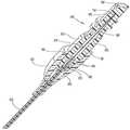
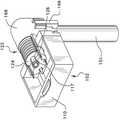
도 1 내지 도 5를 참조하면, 열팽창 보상을 갖는 광섬유 케이블 조립체(20)가 도시된다. 광섬유 케이블 조립체(20)는 광섬유 케이블(25)에서 종결되는 렌즈를 갖는 페룰(lensed ferrule) 부재(22)를 포함한다. 광섬유 케이블(25)은 코어와 클래딩 층을 포함하는 유리 광섬유(26)를 갖는다. 외부 덮개(sheath) 또는 버퍼(27)가 광섬유(26)를 둘러싼다. Kevlar®와 같은 강성 부재가 광섬유(26)와 버퍼(27) 사이에 제공될 수 있다. 대체로 환형인 유지 또는 크림프(crimp) 링(23)이 광섬유 케이블(25)에, 그리고 렌즈를 갖는 페룰 부재(22) 내에 고정된다. 조립체를 밀봉하고 장력 완화를 제공하도록 탄성 부트(24)가 렌즈를 갖는 페룰 부재(22)의 후방 섹션(33) 상에 위치된다.Referring to Figures 1-5, an optical
렌즈를 갖는 페룰 부재(22)는 대체로 원통형이고, 중심축(32)을 따라 페룰 부재를 통해 부분적으로 연장되는 중심 보어를 갖는다. 렌즈를 갖는 페룰 부재(22)는 후방 섹션(33), 중심 섹션(34) 및 전방 또는 정합 섹션(35)을 갖는다. 후방 섹션(33)은, 중심축(32)을 중심으로 원주 방향으로 이격되어 있는 복수의 탄성 래칭 아암(36)을 포함하고, 래칭 아암(36)의 각각의 쌍들 사이에 종방향 슬롯(37)을 갖는다. 후방 섹션(33)은 테이퍼진 도입 섹션(39)을 구비한, 대체로 원통형인 보어(38)를 갖는다. 원통형 보어(38)는 그 안에 보유 링(23)을 고정하여 수용하기 위한 대체로 환형인 내부 리세스(40)를 포함한다.The
중심 섹션(34)은 대체로 원통형이고, 부트 시일(24)의 내부면에 위치된 환형 릿지(49)를 고정하여 수용하기 위한 외부 환형 리세스(43)를 갖는다. 중심 섹션(34)은, 이하에서 보다 상세히 설명하는 바와 같이 광섬유(26)가 그 안에서 측방향으로 이동할 수 있는, 대체로 원통형인 내부 보어(44)를 갖는다.The
전방 섹션(35)은 대체로 원통형이고, 그것의 전방 단부에 일체식으로 형성된 볼록 렌즈(45)를 갖는다. 원한다면, 렌즈(45)는 별개의 부품일 수 있다. 전방 섹션(35)은 대체로 중심 섹션(34)의 내부 보어(44)와 대체로 동일한 직경에서부터 광섬유(26)의 전방 단부(28)와 정렬되도록 감소된 직경부(47)까지 테이퍼진 보어(46)를 갖는다. 전방 섹션(35)은 원한다면 광섬유 케이블 조립체(20)의 장착을 돕기 위해, 하나 이상의 환형 돌출부(48)를 가질 수 있다. 이러한 환형 돌출부(48)는 생략될 수 있고, 전방 섹션(35)의 외부 표면은 원한다면 다른 구성 또는 또 다른 형상을 가질 수 있다.The
도 3에 가장 잘 도시된 바와 같이, 렌즈를 갖는 페룰 부재(22)의 중심 보어는 후방 섹션(33)의 원통형 보어(38), 중심 섹션(34)의 내부 보어(44) 및 전방 섹션(35)의 테이퍼진 보어(46)를 순차적으로 포함한다. 중심 보어는 그 안에 광섬유(26)의 벗겨진 부분을 수용한다. 중심 보어의 직경은 광섬유(26)가 그 안에서 측방향으로 이동하는 것을 허용하도록 충분히 크다. 달리 말하면, 중심 보어는, 도 3 내지 도 5에서 가상선(26')으로 도시된 바와 같이 광섬유가 측방향으로 편향되어 중심축(32)으로부터 멀리 이동하는 것을 허용하도록 충분히 크다.3, the central bore of the
렌즈를 갖는 페룰 부재(22)는 사출 성형될 수 있는 광학 등급 수지로 형성될 수 있다. 렌즈(45)가 렌즈를 갖는 페룰 부재(22)의 일부로서 일체식으로 성형되면, 수지는 광섬유(26)의 굴절률과 거의 일치되는 굴절률을 갖도록 선택될 수 있다. 일 예에서, 렌즈를 갖는 페룰 부재(22)는 Ultem 2500®으로 제조될 수 있다. 렌즈(45)가 렌즈를 갖는 페룰 부재(22)와 일체식으로 성형되지 않으면, 렌즈를 갖는 페룰 부재의 수지가 광섬유(26)의 굴절률과 일치되도록 할 필요가 없어진다. 이러한 별개의 렌즈가 광섬유(26)의 굴절률과 일치하는 것은 여전히 바람직할 가능성이 높다.The
대체로 환형인 보유 링(23)은 그 안에 광섬유 케이블(25)을 수용하기 위한 원통형 보어(29)를 갖는다. 보유 링(23)이 광섬유 케이블(25)에 크림핑되어 고정되는 것을 허용하도록 보유 링(23)은 황동과 같은 변형 가능한 재료로 제조될 수 있다. 원한다면, 보유 링(23)은 에폭시를 포함하는 접착제와 같은 기타 방식으로 광섬유 케이블(25)에 고정될 수 있다.The generally
부트(24)는 렌즈를 갖는 페룰(22)의 후방 섹션(33) 위로활주되도록 구성되는 대체로 탄성의 중공 부재이며, 대체로 렌즈를 갖는 페룰 부재(22), 보유 링(23) 및 광섬유 케이블(25)의 조립체를 밀봉한다. 또한, 부트(24)는 장력 완화의 작용을 할 수 있다. 부트(24)는 렌즈를 갖는 페룰 부재(22)의 외부 환형 리세스(43)와 고정 결합하도록 그 내부 표면을 따라 환형 돌출 릿지 또는 돌출부(49)를 갖는다. 부트(24)는 고무와 같은 탄성 재료로 제조될 수 있다.The
조립시에, 부트(24)가 광섬유 케이블(25) 상에 우선 배치된다. 그 후 보유 링(23)이 적절한 크림핑 공구 내에 위치될 수 있고 광섬유 케이블(25)이 보유 링(23)의 중심 보어(29)를 통해 공급될 수 있다. 보유 링(23)은 크림핑 등에 의해 광섬유 케이블(25)에 고정되고, 일정 길이의 광섬유(26)가 드러나도록 미리 정해진 길이의 버퍼(27)가 제거된다. 그 후 광섬유(26)는 이어서 미리 정해진 길이로 절단된다. 이러한 절단 동작은 레이저 또는 기계적 클리빙(cleaving) 공구로 행해질 수 있다.At the time of assembly, the
광섬유 케이블(25)과 보유 링(23)의 조립체는 렌즈를 갖는 페룰 부재(22)의 중심 보어에 진입하도록 렌즈를 갖는 페룰 부재(22)에 대해 이동된다. 광섬유 케이블(25)과 보유 링(23)의 조립체가 중심 보어 내로 이동함에 따라, 광섬유(26)의 단부는 테이퍼진 보어(46)에 의해 감소된 직경 섹션(47)으로 안내되고, 보유 링(23)은 탄성 래칭 아암(36)의 테이퍼진 도입 섹션(39)과 결합된다. 탄성 래칭 아암(36)은 외향으로 편향되어, 보유 링(23)이 대체로 환형인 내부 리세스(40) 내로 진행하여 그 안에서 고정되는 것을 허용한다. 그 후, 환형 돌출부(49)가 렌즈를 갖는 페룰 부재(22)의 중심 섹션(34)의 외부 환형 리세스(43)와 결합할 때까지, 부트(24)는 광섬유 케이블(25)을 따라 렌즈를 갖는 페룰 부재(22)쪽으로 활주된다.The assembly of the
차량의 엔진 격실 내에서와 같은 환경에서, 광섬유 케이블 조립체(20)는 -60℃ 내지 +150℃ 의 상당한 온도 변화를 받을 수 있다. 렌즈를 갖는 페룰 부재(22)와 광섬유(26)는 상이한 재료로 형성되기 때문에, 상이한 열팽창 계수를 갖고, 따라서 상이한 양으로 팽창 및 수축될 것이다. 보다 구체적으로, 렌즈를 갖는 페룰 부재(22)는 수지로 제조되어, 대체로 실리카 와 같은 유리로 제조된 광섬유(26)보다 큰 크기로 팽창 및 수축되는 경향이 있을 것이다. 따라서, 렌즈를 갖는 페룰 부재(22)의 중심 보어는 광섬유(26)의 직경보다 실질적으로 큰 치수를 가짐으로써, 광섬유 조립체(20)의 중심축(32)에 대해 측방향으로 광섬유가 이동하는 것을 허용한다. 광섬유(26)는 유리로 만들어지고, 그 길이는 온도에 상관없이 매우 안정적이 될 것이다. 렌즈를 갖는 페룰 부재(26)는 광섬유(26)보다 더 큰 크기로 고온시 팽창하고 저온시 수축될 것이다.In an environment such as in the engine compartment of a vehicle, the fiber
일 실시예에서, 광섬유(26)의 노출된 길이는 8 내지 15mm 이고 중심 보어의 직경이 대략 1.5mm일 것으로 예상된다. 이러한 구성으로, 광섬유(26)의 전방 단부(28)와 보유 링(23) 사이의 거리는, 광섬유 케이블 조립체(20)가 -60℃ 내지 +150℃의 온도 범위에 걸친 열팽창을 경험함에 따라, 대략 20마이크로미터만큼 변화할 수 있다. 중심 보어의 직경을 대략 1.5mm로 구성하는 것은, 광섬유 케이블 조립체의 열팽창에 대한 보상을 허용하도록 중심축(32)으로부터 멀어지는 광섬유(26)의 편향을 허용하는데 충분하다고 예상된다.In one embodiment, the exposed length of the
도 3 및 도 4에는, 광섬유가 중심축(32)을 따라 그 정상 길이로 팽창될 수 있도록 렌즈를 갖는 페룰 부재(22)가 충분히 팽창되어 있을 때의 광섬유(26)가 "실선"으로 도시되어 있다. 작동 온도가 내려감에 따라, 렌즈를 갖는 페룰 부재(22)는 수축될 것이다. 광섬유(26)는 감소된 직경 보어(47)와 보유 링(23) 사이에 고정되어, 렌즈를 갖는 페룰(22)이 수축되어 있는 동안 광섬유는 압축 상태로 배치된다. 그러나, 광섬유(26)가 렌즈를 갖는 페룰 부재(22)의 중심 보어 내에서는 지지되지 않기 때문에, 광섬유(26)의 전방 단부(28)가 감소된 직경의 보어(47)에 유지되는 동안 광섬유(26)는 도면부호 26'에서 가상선으로 도시된 바와 같이 중심 보어(32) 내에서 중심축(32)으로부터 편향될 수 있다. 이러한 구성으로, 렌즈를 갖는 페룰 부재(22)와 광섬유(26) 사이의 열팽창의 차이에 대한 보상은, 광섬유 케이블 조립체(20)의 성능을 저하시키지 않고 달성 가능하다. 명확하게 하기 위해, 렌즈를 갖는 페룰 부재(22)의 상이한 길이(팽창 및 수축)는 도시되지 않는다는 점에 유의한다. 실제로는, 렌즈를 갖는 페룰 부재(22)가 수축 위치에 있고 광섬유(26')가 중심축(32)으로부터 측방향으로 이동될 때, 렌즈(45)는 도 3 내지 도 5에서 도시된 것보다 더 보유 링(23) 쪽으로 근접하게 이동할 것이다.3 and 4 show that the
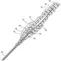
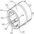
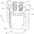
열팽창 보상을 갖는 광섬유 케이블 조립체(50)의 제2 실시예는 도 6 내지 도 9에 도시된다. 광섬유 케이블 조립체(50)는 광섬유 케이블(25)에서 종결되는 렌즈를 갖는 페룰 부재(51)를 포함한다. 광섬유 케이블(25)은 도 1 내지 5의 실시예와 유사한 방식으로 구성되지만, 짧은 길이의 노출된 광섬유(26)가 남도록 짧은 길이의 버퍼(27)가 벗겨진다. 보유 또는 크림프 링(53)이 광섬유 케이블(25) 및 렌즈를 갖는 페룰 부재(51)에 고정된다. 탄성 부트(54)가 렌즈를 갖는 페룰 부재(51)의 후방 섹션(55)과 보유 링(53) 위로 위치되어 조립체를 밀봉하고, 장력을 완화하는, 렌즈를 갖는 페룰 부재(51)를 제공한다.A second embodiment of an optical
렌즈를 갖는 페룰 부재(51)는 대체로 원통형이고, 중심축(60)을 따라 페룰 부재를 통해 연장되는 중심 보어(52)를 갖는다. 렌즈를 갖는 페룰 부재(51)는 후방 섹션(55), 중심 섹션(56) 및 전방 또는 정합 섹션(57)을 포함한다. 후방 섹션(55)은 중심축(60)을 중심으로 원주 방향으로 이격된 복수의 탄성 래칭 아암(58)을 갖고, 각각의 탄성 래칭 아암(61) 사이에는 종방향 슬롯(59)이 위치된다. 각각의 탄성 래칭 아암(58)은 대체로 원형인 로킹 링(62)을 형성하도록 집합적으로 조합된 상승 외부 에지(61)를 갖는다. 도 8 및 도 9를 참조하면, 후방 섹션(55)이 그 안에 원통형 보어(64)를 갖는다는 것을 알 수 있다.The
중심 섹션(56)은 대체로 원통형이고, 부트(54)에 렌즈를 갖는 페룰 부재(51)를 고정하기 위한 외부 환형 리세스(65)를 갖는다. 중심 섹션(56)은 대체로 원통형인 보어(66)이다.The
전방 섹션(57)은 대체로 원통형이며, 일련의 통로로 형성되고 그 전체 길이를 통해 연장되는 단차식 내부 보어를 갖는다. 전방 섹션은 후방벽(79)에 도달할 때까지 중심 섹션(56)쪽으로 후방으로 연장되는 대체로 원통형인 전방 통로(71)를 구비한 전방 단부(68)를 갖는다. 한 쌍의 측방향 개구(72)가 전방 섹션(57)의 외부면으로부터 연장되고, 후방벽(79) 보다 약간 전방의 위치에서 전방 통로(71)와 교차한다.The
전방 섹션(57)은 중심 섹션(56)에 인접하여 보어(66)의 연장부로서 구성된 대체로 원통형인 통로(73)를 갖는다. 보어는 후방벽(79)에 접근함에 따라, 광섬유 통로(75)로 안내하는 테이퍼진 통로(74)를 형성하도록 테이퍼진다. 광섬유 통로(75)는 중심축(60)을 따라 위치되고, 후방벽(79)을 통해 연장되어 전방 통로(71)를 테이퍼진 통로(74)와 연결한다.. 테이퍼진 통로(74) 및 광섬유 통로(75)는 광섬유가 전방 통로(71)에 접근함에 따라, 중심축(60)으로 광섬유를 안내하도록 구성된다. 전방 섹션(57)은 원한다면 광섬유 케이블 조립체(50)를 장착하는 것을 돕도록 환형 돌출부(67)를 가질 수 있다. 이러한 환형 돌출부(67)는 생략될 수 있고, 전방 섹션(57)의 외부면은 원한다면 다른 구성 또는 또다른 형상을 가질 수 있다.The
도 8 및 도 9에서 가장 잘 도시된 바와 같이, 렌즈를 갖는 페룰 부재(51)의 중심 보어(52)는 후방 섹션(55)의 원통형 보어(64), 중심 섹션(56), 및 전방 섹션(57)의 원통형 통로(73)의 원통형 보어(66), 테이퍼진 통로(74), 광섬유 통로(75) 및 전방 통로(71)를 순서대로 포함한다. 중심 보어(52)는 그 안에 일정 길이의 광섬유 케이블(25) 뿐만 아니라 일정 길이의 벗겨진 광섬유(26) 를 수용한다. 후방 섹션(55)의 원통형 보어(64), 중심 섹션(56)의 원통형 보어(66) 및 전방 섹션(57)의 원통형 통로(73)의 직경들은, 광섬유 케이블이 그 안에 위치되는 것을 허용하도록 충분히 크다. 광섬유 통로(75)는 광섬유(26)가 이를 통과하고 중심축(60)을 따라 광섬유를 유지하도록 치수가 결정된다. 렌즈를 갖는 페룰 부재(51)는 사출 성형이 가능한 수지로 형성될 수 있다.8 and 9, the
탄성 렌즈(76)가 전방 통로(71) 내에 인서트 성형되어, 볼록한 전방 표면(77)이 구성되고, 그 외에도 탄성 렌즈 재료로 전방 통로(71)와 측방향 개구(72)를 충진한다. 탄성 렌즈 재료는 (성형 프로세스 이후에) 전방 통로(71) 내에서 탄성 렌즈(76)를 유지하도록 기능하는 레그(78)로 렌즈를 갖는 페룰 부재(51)의 측방향 개구(72)를 충진한다. 성형 프로세스 동안, 하나의 레그(72)가 렌즈 재료용 입구로서 작용하고, 다른 레그가 출구로서 작용한다. 그 결과, 전방 통로(71) 내에 공기가 갖힐 가능성이 감소될 수 있고, 따라서 탄성 렌즈(76)의 성능을 증가시킨다. 탄성 렌즈(76)는 광섬유(26)의 굴절률과 거의 일치하는 굴절률을 갖는 사출 성형 가능한 광학 등급 탄성 재료로 제조될 수 있다. 일 예에서, 탄성 렌즈는 실리콘으로 제조될 수 있다.The
대안적인 설계에서, 탄성 렌즈는 렌즈를 갖는 페룰 부재(51)와 별개로 성형되어 전방 통로(71) 내로 삽입될 수 있다. 또한, 이러한 별개의 렌즈(도시 안함)는 측방향 개구(72)와 결합하여 렌즈를 전방 통로(71)내에 고정시키는 돌출부를 가질 수 있다.. 또한, 이러한 별개의 렌즈(도시 안함)는 렌즈를 갖는 페룰 부재(51)의 전방 단부(68) 너머로 연장되는 단부를 가질 수도 있다. 이러한 구성에서, 렌즈를 갖는 페룰 부재(51)의 탄성면(elastic face)은 후방 Z축 힘을 발생시킬 수 있다. 이러한 Z축 힘은 렌즈를 갖는 페룰 부재(51)의 프로파일을 그것의 인클로저 내의 공지된 정지부로 이동시킬 수 있다. 따라서, 이러한 탄성면을 달성하기 위해, 두 개의 대향하는 페룰 사이에 배치되어 스프링 부재로서 작용하는 별개의 요소를 갖는 것이 가능하고; 단부는 렌즈를 갖는 페룰 부재(51)의 전방 단부(68) 너머로 연장한다. 대안적인 접근법으로서, 탄성면의 통합이 페룰의 실리콘 렌즈의 형성과 동일한 프로세스로부터 형성될 수 있다. 어느 쪽이든, 이러한 구성은 Z축 방향으로 바이어스되는 그것의 하우징 내에 조립된 페룰을 갖도록 하여, 정합시에, 페룰과 대향 페룰 사이의 공지된 거리가 서로에 대해 공지된 배향이 되도록 한다.In an alternative design, the resilient lens can be molded separately from the
보유 링(53)은 대체로 원통형이며 단차를 갖는 구성을 갖는다. 후방 섹션(81)은 그 내부에 광섬유 케이블(25)을 수용하기 위한 치수를 갖는 원통형 보어(82)를 갖는다. 전방 섹션(83)은 후방 섹션(81)의 외경보다 큰 외경을 갖는다. 전방 섹션(83)은 렌즈를 갖는 페룰 부재(51)의 래치 아암(58)의 단부(61)들을 수용하도록 확대 보어(84)를 갖는다. 확대 보어(84)는 테이퍼진 선단 에지(85)와, 후방부(81)와 테이퍼진 선단 에지(85) 사이의 환형 리세스(86)를 가질 수 있다. 환형 리세스(86)는 페룰 부재(51)의 탄성 스프링 아암(58)의 상승 외부 에지(61)에 의해 형성된 로킹 링(62)을 고정하여수용하도록 치수가 결정된다. 보유 링(53)은, 보유 링이 광섬유 케이블(25)에 크림핑되어 고정되는 것을 허용하도록 황동과 같은 변형 가능 재료로 형성될 수 있다. 원한다면, 보유 링(53)은 에폭시를 포함하는 접착제와 같은 기타 방식으로 광섬유 케이블(25)에 고정될 수 있다.The retaining
부트(54)는 렌즈를 갖는 페룰 부재(51)의 후방 섹션(55) 상을 활주하도록, 그리고 렌즈를 갖는 페룰 부재(51), 보유 링(53) 및 광섬유 케이블(25)의 조립체를 대체로 밀봉하도록 구성되는 대체로 탄성인 중공 부재이다. 또한, 부트(54)는 장력 완화의 작용을 할 수 있다. 부트(54)는 렌즈를 갖는 페룰 부재(51)의 외부 환형 리세스(65)와 고정 결합되도록 그것의 내부면을 따르는 환형 돌출 릿지 또는 돌출부(88)를 갖는다. 부트(54)는 고무와 같은 탄성 재료로 제조될 수 있다.The
조립 동안, 부트(54)는 광섬유 케이블(25)에 우선 위치된다. 보유 링(53)이 적절한 크림프 공구(도시 안함) 내에 배치되고, 광섬유 케이블(25)이 보유 링(53)의 보어(82) 및 보어(84)를 통해 공급될 수 있다. 보유 링(53)은 크림핑 등에 의해 광섬유 케이블(25)에 고정되고, 일정 길이의 광섬유(26)가 드러나도록 미리 정해진 길이의 버퍼(27)가 제거된다. 이어서 광섬유(26)는 미리 정해진길이로 절단된다. 이러한 절단 동작은 레이저 또는 기계적 클리빙 공구로 행해질 수 있다.During assembly, the
광섬유 케이블(25)과 보유 링(53)의 조립체는 렌즈를 갖는 페룰 부재(51)의 중심 보어(52)에 진입하도록 렌즈를 갖는 페룰 부재(51)에 대해 이동된다. 광섬유(26)가 광섬유 보어(75) 내로 진입함에 따라서, 렌즈를 갖는 페룰 부재(51)의 탄성 아암(58)은, 보유 링(53)의 테이퍼진 선단 에지(85)와 결합되어 내향으로 편향된다. 탄성 아암(58)의 상승된 외부 에지(61)가 보유 링(53)의 환형 리세스(86)와 정렬되면, 에지(61)가 환형 리세스(86)와 결합된 상태로 탄성 아암이 외향으로 스냅 결합되어 렌즈를 갖는 페룰 부재(51)를 보유 링(53)에 고정시킨다. 이어서 탄성 부트(54)의 환형 돌출부(88)가 렌즈를 갖는 페룰 부재(51)의 중심 섹션(56)의 외부 환형 리세스(65)와 결합할 때까지, 탄성 부트(54)가 광섬유 케이블(25)을 따라서 렌즈를 갖는 페룰 부재(51)와 보유 링(53)의 조립체 상에서 활주한다.The assembly of the
광섬유(26)와 렌즈를 갖는 페룰 부재(51) 사이의 열팽창의 차이는 렌즈(76)의 탄성에 의해 극복될 수 있다. 광섬유 케이블 조립체(50)는, 광섬유 케이블 조립체(50)가 그것의 예상 온도 범위의 상한에 있을 때, 원하는 광학 투과성을 제공하기 위해 광섬유(26)의 전방 단부(28)가 충분한 힘으로 렌즈(76)의 후방 표면(89)과 결합하도록 구성된다. 광섬유 케이블 조립체(50)가 이러한 온도 범위의 상한보다 낮은 온도에 직면하면, 광섬유(26)는 대체로 동일한 길이로 유지되면서 렌즈를 갖는 페룰 부재(51)는 수축할 것이다. 렌즈를 갖는 페룰 부재(51)가 수축함에 따라, 전방 통로(71)는 보유 링(53)을 향해 후방으로 이동할 것이고, 따라서 보유 링(53)과 탄성 렌즈(76)의 후방 표면(89) 사이의 거리가 짧아진다. 광섬유(26)의 길이는 상당히 크게 변화하지는 않기 때문에, 광섬유(26)의 전방 단부(28)는 탄성 렌즈의 후방 표면(89) 내로 추가적으로 가압되고 탄성 렌즈의 후방 표면(89)을 추가적으로 변형시킬 것이다. 탄성 렌즈의 후방 표면(89)의 편향에도 불구하고, 원하는 광학 투과 특성이 유지될 것이다. -60℃ 내지 +150℃의 온도 범위에 대해, 렌즈의 후방 표면(89)은 중심축(60)을 따라 대략 20마이크로미터만큼 이동할 수 있을 것으로 예상된다. 광섬유 케이블 조립체(20)와 광섬유 케이블 조립체(50)는 케이블 조립체의 열팽창 보상 양태에 상당한 영향을 끼치지 않고 변경될 수 있는 부품들을 각각 포함한다는 점에 유의한다. 예를 들어, 광섬유 케이블 조립체(20)와 광섬유 케이블 조립체(50)는 광섬유 케이블(25)을 각각의 렌즈를 갖는 페룰 조립체 내에 유지하기 위해 상이한 구성을 이용한다. 보다 구체적으로, 광섬유 케이블 조립체(20)의 보유 링(23)은 렌즈를 갖는 페룰 부재(22)의 탄성 래칭 아암(36) 내로 활주하지만 광섬유 케이블 조립체(50)의 보유 링(53)은 렌즈를 갖는 페룰 부재(51)의 탄성 래칭 아암(58) 상에서 활주한다. 광섬유(25)를 렌즈를 갖는 페룰 부재들에 고정하기 위한 각각의 구성은 어느 쪽의 케이블 조립체에도 사용될 수 있다. 또한, 광섬유 케이블(25)을 렌즈를 갖는 페룰 부재들에 고정하기 위한 다른 방식도 사용될 것이라는 것이 예상된다. 또한, 각각의 렌즈를 갖는 페룰 부재들의 전방 섹션의 외부 구성은, 광섬유 케이블 조립체들의 열팽창 보상 성능에 상당한 영향을 주지 않고 변경될 수 있다.The difference in thermal expansion between the
광섬유 케이블 조립체(20)는 중심 보어 내의 광섬유(26)의 측방향 편향을 허용함으로써 중심축 또는 종방향 축(32)을 따른 광섬유(26)와 렌즈를 갖는 페룰 부재(22)의 열팽창 사이의 차이를 보상한다. 달리 말하면, 광섬유 케이블 조립체(20)는 광섬유(26)의 측방향 편향을 통해 열팽창을 보상한다. 광섬유 케이블 조립체(50)는 중심축(60)을 따라 편향되는 탄성 렌즈(76)를 제공함으로써 광섬유(26)와 렌즈를 갖는 페룰 부재(51) 사이의 열팽창의 차이를 보상한다. 달리 말하면, 광섬유 케이블 조립체(20)는 광섬유(26)의 측방향 편향을 통해 열팽창을 보상하지만, 광섬유 조립체(50)는 탄성 렌즈(76)의 종방향 편향을 통해 열팽창을 보상한다.The fiber
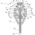
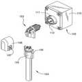
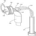
도 10 내지 도 21을 참조하면, 디지털 카메라, DVD 플레이어, 제어 시스템 또는 엔진 관리 시스템과 같은 전자 장치(도시 안함)로부터의 고 대역폭 신호 전송용 시스템(100)이 도시된다. 시스템(100)은 장치 소조립체(102), 장치 소조립체(102)에 접속되는 트랜스시버 소조립체(103), 트랜스시버 소조립체(103)에 접속되는 케이블 조립체(104)를 포함한다. 장치 소조립체(102)는 고품질의 디지털 신호를 송신 및/또는 수신하는데 유용한 임의의 종류의 전자 장치(도시 안함)를 포함한다. 장치 소조립체(102)는 임의의 형상을 가질 수 있지만, 대체로 직사각형으로 도시되어 있고, 그 위에 대체로 원형인 커넥터(111)를 갖는 하우징(110)이 장착된다. 원형 커넥터(111)는 정합 커넥터를 수용하기 위한 대체로 원형인 개구(112)를 갖고, 원형 개구(112) 내로 연장되는 복수의 도전성 탄성 단자(113)를 갖는다. 각각의 단자(113)는 정합 커넥터의 도전성 접점(125)과 접촉하기 위한 돌출부 또는 딤플(115)을 구비한 접촉 아암(114)을 갖는다. 도전성 단자(113)의 딤플(115)은 이하에서 보다 상세히 후술하는 바와 같이 원형 커넥터의 정합 에지(116)로부터 상이한 거리로 이격될 수 있다는 점에 유의한다. 원형 커넥터(111)의 단자(113)는 하우징(110) 내의 전자 부품(도시 안함)에 전기 접속되고, 납땜 등에 의해서 회로 기판(도시 안함)을 통해 접속될 수 있다.10 to 21, there is shown a
트랜스시버 소조립체(103)는 장치 접속 단부(122)와 케이블 접속 단부(123)를 포함하는 하우징(121)을 갖는다. 장치 접속 단부는, 개별 주연 방향 접점(125)으로서 기능하는 복수의 이격된 주연 방향 도전성 링을 구비한 원통형 돌출부(124)를 갖는다. 돌출부(124) 및 그것의 접점(125)은, 회전식 커넥터를 형성하기 위해 원형 커넥터(111)의 단자(113)와 상호 작용하는 도전성 슬립 링으로서 기능한다. 하우징 단부(122)는, 장치 소조립체(102)의 원형 커넥터(111)에 트랜스시버 소조립체(103)를 고정하도록 원형 커넥터(111)의 견부(117)와 고정 결합되는 복수의 탄성 로킹 아암(127)을 갖는 로킹 돌출부(126)를 가질 수 있다.The
트랜스시버 소조립체(103)의 케이블 접속 단부(123)는 한 쌍의 전력 단자(131), 송신기 광학 소조립체(TOSA)(135) 및 수신기 광학 소조립체(ROSA)(136)를 포함한다. 각각의 전력 단자(131)는 케이블 조립체(104)의 커넥터 조립체(155)의 정합 가능 단자(157)에 제거 가능하게 접속되는 도전성 접점(132)을 갖는다. 도전성 리드(133)가 각각의 접점(132)으로부터 연장되고, 하우징(121)의 원통형 돌출부(124)에 위치된 원주 방향 접점(125) 중 하나에 전기 접속된다.The
TOSA(135)는 전기 신호를 광학 신호로 변환하기 위한 회로(도시 안함)와 함께 광학 인터페이스(139)를 갖는다. 3개의 도전성 리드(141)가 TOSA(135)로부터 하우징(121)의 원통형 돌출부(124) 내로 연장되고, 원통형 돌출부(124)에 위치된 원주 방향 접점(125)에 전기 접속된다. TOSA(135)의 리드(141) 중 하나는 전력 단자(131) 중 하나의 리드(132)로서 동일한 원주 방향 접점(125)에 전기 접속될 수 있다. 이러한 구성은 하우징(110) 내의 전자 장치 뿐만 아니라 TOSA(135) 및 ROSA(136)에 전력을 제공하도록 사용될 수 있다. TOSA(135)는 케이블 조립체(104)의 광섬유 커넥터(158)와 같은 정합 광학 부품들을 수용하기 위한 대체로 원통형인 보어(138)를 구비한 대체로 원통형인 어댑터(137)를 가질 수 있다.The
TOSA(135)의 광학 인터페이스는 다양한 형상을 취할 수 있다. 도 10 내지 도 21에 도시된 실시예에서, 광학 인터페이스는 정합 인터페이스에서 광학을 확대 및 축소시키는데 렌즈를 사용하는 확장 비임 광학 인터페이스이다. 보다 구체적으로, 확장 비임 커넥터는 광학 비임의 폭을 확장시키고, 커넥터들 사이의 공기 간극을 가로질러 확장된 비임을 송신한다. 비임을 확장함으로써, 임의의 먼지 또는 파편과 빔 사이의 상대 크기 차이가 증가되어 커넥터의 오정렬뿐만 아니라, 먼지 또는 파편 중 어느 하나가 효율에 미치는 영향을 감소시킨다. 광학 비임이 공기 간극을 통과한 후, 제2 렌즈는 광섬유 상으로의 비임을 축소시키거나 재포커스한다.The optical interface of the
ROSA(136)는 광학 신호를 수신하여 이를 전기 신호로 변환하도록 동작한다는 점을 제외하고는 TOSA(135)와 실질적으로 동일한 방식으로 구성된다. 달리 말하면, TOSA(136) 및 ROSA(136)는 트랜스시버 소조립체(103) 내에서 물리적으로 유사한 방식으로 구성되지만, 대체로 반대의 기능성을 갖는다. 그들의 공통 요소들은 본원에서 설명되지 않고, 공통 도면 부호를 공유한다. TOSA(135)와 ROSA(136)는 원한다면 단일 트랜스시버 유닛(도시 안함)으로 교체될 수 있다. 또한, 송신이 일방향으로만 요구되면, 하나의 TOSA(135) 또는 ROSA(136)만이 사용될 수 있다.
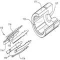
케이블 조립체(104)는 내부에 두 개의 광섬유(152)와 두 개의 전기 도전성 와이어(153)를 갖는 하이브리드 케이블(151)로서 도시된다. 케이블(151)은 그것의 외부 표면을 둘러싸는 보호 덮개(154)를 가질 수 있다. 케이블(151)은 커넥터 조립체(155)에서 종결된다. 커넥터 조립체(155)는 두 개의 전기 단자(157)와 두 개의 광섬유 커넥터(158)를 지지하는 하우징(156)을 갖는다. 전기 단자(157)는 도전성 와이어(153)에서 종결된다. 광섬유 커넥터(158)는 광섬유(152)에서 종결된다. 도시된 바와 같이, 광섬유 커넥터(158)는 전술한 도 1 내지 도 9에 도시된 광섬유 케이블 조립체(20, 50)에서 종결되는 열팽창 보상 커넥터일 수 있다. 대안적으로, 광섬유 커넥터는 확장 비임 또는 그 이외의 것이든지 간에 다른 종류의 커넥터일 수 있다. 경우에 따라, 유리 광섬유(152) 대신에 플라스틱 광섬유를 사용하는 것이 바람직할 수 있다.The
커넥터 조립체(155)는 트랜스시버 소조립체(103)에 대해 커넥터 조립체(155)를 해제 가능하게 래치하기 위해 래치(165)를 갖는다. 래치(165)는 커넥터 조립체(155)를, 그리고 그에 따라서 케이블 조립체(104)를 트랜스시버 소조립체(103)에 고정하기 위해 커버(168)의 릿지(167)와 결합하는 한 쌍의 편향 가능 비임(166)을 갖는다.소조립체The
장치 소조립체(102)는 원형 커넥터(111)가 도전성 단자(113)를 통해 전자 장치에 전기 접속되는 상태로 하우징(110) 내에 전자 장치(도시 안함)를 장착함으로써 조립될 수 있다. 트랜스시버 소조립체(103)는, 각각의 전력 단자(131)의 리드(133)가 원통형 돌출부(124) 내로 연장되는 상태로 하우징(121) 상에 전력 단자(131) 각각을 장착함으로써 조립될 수 있다. 각각의 리드는 각각의 원통형 돌출부의 주연 방향 접점(125)들 중 하나에 전기 접속된다. TOSA(135)와 ROSA(136)는 TOSA(135) 및 ROSA(136) 각각으로부터의 리드(141)들이 원통형 돌출부(124) 내로 연장되는 상태로 하우징(121)에 각각 장착된다. 각각의 리드는 원통형 돌출부(124)들의 원주 방향 접점(125)들에 전기 접속된다.The
케이블 조립체(104)는 케이블(151)의 도전성 와이어(153)들과 광섬유(152)들로부터 덮개를 소정의 길이로 벗겨냄으로써 조립된다. 전기 단자(157)들은 전기 도전성 와이어(153)들에서 종결된다. 광섬유(152)들은 광섬유 커넥터(158)들에서 종결된다. 종결된 전기 단자(157)들과 광섬유 커넥터(158)들은 하우징(156) 내에 장착될 수 있고, 하우징은 케이블(151)에 고정될 수 있다.The
트랜스시버 소조립체(103)를 장치 소조립체(102)에 상호 접속하기 위해, 트랜스시버 소조립체(103)의 원통형 돌출부(124)는 원형 커넥터(111)의 원통형 개구(112) 내로 삽입되어, 원주 방향 접점(125)들이 원형 커넥터(111)의 단자(113)들과 결합된다. 단자(113)의 엇갈린 딤플(115)들은 각각의 단자(113)가 단자와 정렬된 하나의 원주 방향 접점(125)과 결합되는 것을 허용한다. 로킹 돌출부(126)는 원형 커넥터(111)의 원통형 개구(112)의 단부를 통해 연장되고, 장치 소조립체(102)에 트랜스시버 소조립체(103)를 고정하도록 견부(117)와 고정 결합된다. 커버(168)는 트랜스시버 소조립체(103)에 장착될 수 있다. 커넥터 조립체(155)는 TOSA(135) 및 ROSA(136)와 함께 전력 단자(131)들과 정렬되고, 커넥터 조립체(155)는 트랜스시버 소조립체(103)쪽으로 이동하여 래치(165)가 커버(168) 상에서 활주하여 커버의 릿지(167)와 결합되어 케이블 조립체(104)를 트랜스시버 소조립체(103)에 고정시킨다. 이러한 구성으로, 트랜스시버 소조립체(103)는 원형 커넥터(111)와 원통형 돌출부(124)를 통과하는 축(149)을 중심으로 360도 회전을 통해 자유롭게 회전할 수 있다. 전기 신호로부터 광학 신호로의 변환이 장치 소조립체(102)의 외측에서, 그리고 장치 소조립체(102)와 트랜스시버 소조립체(103) 사이의 인터페이스 이후에 발생하기 때문에, 장치 소조립체(102)에 대한 케이블 조립체(104)의 회전은 상당히 단순화된다.The
도 22 및 도 23을 참조하면, 전자 장치(도시 안함)에 대한 신호의 송수신을 위한 접속 시스템(170)의 대안적인 실시예가 도시된다. 한 쌍의 광섬유들을 갖는 대신에, 접속 시스템(170)은 양방향 신호 전송 매체로서 활용되는 단일 광섬유(190)를 갖는다. 전자 장치는 하우징(171) 내에 장착되고 트랜스시버(도시 안함) 또는 TOSA/ROSA(도시 안함)에 접속되어, 하우징(171) 내에 여전히 있으면서, 전자 장치로부터의 전기 신호들을 광학 신호들로 변환한다. 본원에서 사용될 때, 트랜스시버 조립체는 그것이 단일 조립체이건 TOSA 및 ROSA와 같은 두 개의 개별 조립체들이든간에, 단일 광섬유 상에서 광학 신호를 송신 및 수신 가능한 광학 부품을 의미한다. 하이브리드 커넥터(172)가 하우징(171)의 외부 표면으로부터 연장하여 회로 기판(도시 안함) 또는 하우징 내의 다른 부품들에 의해 전자 장치에 전기 및 광학적으로 접속된다. 하이브리드 커넥터(172)는 전기 접속부 및 광학 접속부 양자를 모두 포함한다. 보다 구체적으로, 한 쌍의 이격된 동심형 도전성 접점(173, 174)이 정합축(175)을 중심으로 연장된다. 확장 비임 광학 커넥터 부품(176)이 정합축(175)을 따라 위치될 수 있다.Referring to Figures 22 and 23, an alternative embodiment of an
전기 접속부 및 광학 접속부를 역시 포함하는 정합 하이브리드 커넥터(180)(가상선으로 도시함)가 제공된다. 정합 하이브리드 커넥터(180)에는 한 쌍의 도전성 단자(181, 182)가 장착된다. 각각의 도전성 접점(181, 182)은, 원하는 동심 접점(173, 174)에만 접촉하도록 편향 가능 비임(183)과 돌출부 또는 딤플(184)을 갖는다. 확장 비임 광학 커넥터 부품(185)이 광섬유(190)를 통해 하이브리드 커넥터(172)의 광학 커넥터 부품(176)에 대해 양방향 광학 신호를 송수신하도록 축(175)을 따라 위치될 수 있다. 원하는 경우 두 개의 커넥터들을 함께 고정하도록 하이브리드 커넥터(176, 185)들의 하우징들에 적절한 요소들이 제공될 수 있다. 필요할 때, 정합 하이브리드 커넥터(180)는 하이브리드 케이블, 별개의 전기 케이블 및 광학 케이블 또는 다른 부품에 접속될 수 있다.A matching hybrid connector 180 (shown in phantom) is also provided that also includes electrical connections and optical connections. A pair of
커넥터(172, 180)들 사이의 전기 접속부들은 전자 장치에 필요한 전력을 제공하도록 활용된다. 광학 접속부는 고 대역폭 신호 전송을 위해 활용된다. 이러한 구성으로, 정합 하이브리드 커넥터(180)는 하이브리드 커넥터(172)에 대해 정합축(175)을 중심으로 360도 회전으로 자유롭게 회전할 수 있다. 전기 신호들을 광학 신호들로 변환하는 것은 하우징(171) 내의 또는 그에 인접한 전자 장치 또는 다른 부품들 내에서 이루어질 수 있다. 확장 비임 광학 인터페이스를 활용함으로써, 확장 비임 광학 커넥터 부품(176, 185)들 사이에 접촉이 발생하지 않고, 그에 따라서 마모가 발생하지 않는다. 그 결과, 커넥터들은 광학 신호 전송에 영향을 미치거나 또는 광학 신호 전송을 저하시키는 일 없이 자유롭게 회전된다.The electrical connections between the
대안적으로, 확장 비임 광학 커넥터 부품(176)을 사용하는 것 보다, 정합 하이브리드 커넥터(180)의 확장 비임 광학 커넥터 부품(185)과 함께 동작하는 하이브리드 커넥터(172)와 연관된 트랜스시버 조립체(도시 안함)가 사용될 수 있다. 또한, 트랜스시버 조립체는 정합 하이브리드 커넥터(180)의 비확장 비임 광학 커넥터 부품(도시 안함)과 함께 사용될 수 있다. 어느 경우에도 시스템은 하이브리드 커넥터(172)와 정합 하이브리드 커넥터(180)의 광학 부품들 사이에 공기 갭을 가짐으로써 광학 신호 전송에 영향을 미치거나 광학 신호 전송을 저하시키는 일 없이도 커넥터들 사이의 상대 회전이 이루어질 것이다.Alternatively, a transceiver assembly (not shown) associated with
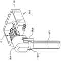
도 24 내지 도 27은 양방향 신호 전송 매체로서 사용되는 단일 광섬유(200)를 갖는, 전자 장치(도시 안함)에 대한 신호의 송수신을 위한 접속 시스템(200)의 다른 대안적인 실시예를 도시한다. 전자 장치는 하우징(201) 내에 장착되고, 정합 하이브리드 조립체(203)에 전자 장치를 광학적으로 그리고 전기적으로 접속하기 위한 하이브리드 커넥터(202)에 접속된다.24-27 illustrate another alternative embodiment of an
하이브리드 커넥터(202)는 전기적 접속부 및 광학적 접속부 양자를 모두 포함한다. 보다 구체적으로, 하이브리드 커넥터(202)는 정합축(207)을 중심으로 연장되는 한 쌍의 이격된 동심형 도전성 접점(205, 206)들을 구비한 접점 회로 기판(204)을 갖는다. 도전성 접점(205, 206)들은 접점 회로 기판(204) 내의 리드(도시 안함)들에 전기 접속된다. 정합축(207)을 중심으로 접점 회로 기판을 통해 홀(209)이 연장될 수 있다. 전자 장치와 트랜스시버 조립체(208)에 전력을 공급하기 위해 전류가 도전성 접점(205, 206)들을 통해 전송될 수 있다.The
트랜스시버 조립체(208)는 정합축(207)을 따라 위치되고, 접점 회로 기판(204)의 홀(209)을 통해 연장될 수 있다. 전력 및 다양한 신호를 운반하는 기능을 위해 복수의 리드(210)들이 트랜스시버 조립체(208)로부터 연장된다. 트랜스시버 조립체(208)는 전자 장치로부터의 전기 신호들을 광학 신호들로 변환하도록 구성되어, 신호들이 단일 광축을 따라 송신 및 수신될 수 있도록 한다. 트랜스시버 조립체(208)는 트랜스시버와 같은 단일 조립체이거나 TOSA 및 ROSA와 같은 두 개의 별개의 조립체들 일 수 있다.트랜스시버 조립체(208)에 의해 송수신되는 신호들은 다양한 방식으로 광학 경로를 따라 보내질 수 있다. 일 실시예에서, 신호들은 축(207)을 따라 순차적으로 보내질 수 있다. 다른 실시예에서, 신호들은 상이한 주파수들로 동시에 보내질 수 있다.The
접점 회로 기판(204)과 트랜스시버 조립체(208)는 전자 장치에 전기 접속된다. 이러한 접속은 회로 기판(도시 안함) 또는 다른 전자 부품들에 대해 접점 회로 기판(204)의 리드(도시 안함)들과 트랜스시버 조립체(208)의 리드(209)들을 접속함으로써 이루어질 수 있다.The
정합 하이브리드 케이블 조립체(203)는 전기적 접속부 및 광학적 접속부를 모두 포함한다. 정합 하이브리드 케이블 조립체(203)는 하이브리드 케이블(211)과 정합 하이브리드 커넥터(212)를 갖는다. 하이브리드 케이블(211)은 한 쌍의 도전체들 또는 와이어(213)들과 단일 광섬유(214)를 갖는다. 광섬유(214)는 유리로 제조될 수 있다. 각각의 도전체(213)들은 그것의 단부에서 종결되는 전기 단자(215)를 갖는다. 전기 단자(215)들은 하이브리드 커넥터(202)의 동심형 도전성 접점(205, 206)들과 버트 접촉(butt contact)을 이루기 위한 스프링 부하식 핀을 포함하는 다양한 형태를 취할 수 있다. 광섬유(214)는 광섬유 커넥터(216)에서 종결된다. 여기에 도시된 바와 같이, 광섬유 커넥터(216)는 전술한 도 1 내지 9에 도시된 광섬유 케이블 조립체(20, 50)에서 종결되는 열팽창 보상 커넥터들일 수 있다. 대안적으로, 광섬유 커넥터들은 확장 비임이든 또는 다른 것이든 간에, 다른 종류의 커넥터들일 수 있다. 소정의 상황에서, 유리 광섬유 대신에 플라스틱 광섬유를 사용하는 것이 바람직할 수도 있다.The matching
정합 하이브리드 커넥터(212)는 2피스의 대체로 원호형인 하우징을 갖는다. 하우징은 내부 부품(218)과 외부 부품(219)을 갖는다. 내부 부품(218)과 외부 부품(219)은 그 사이에 위치된 도전성 와이어(213)들 및 광섬유(214)와 함께 고정된다. 원한다면, 내부 부품(218)과 외부 부품(219) 사이에 시일(220)이 제공될 수 있다. 내부 부품(218)은 전방부(221)를 가지며, 그로부터 전기 단자(215)들과 광섬유 커넥터(216)가 하이브리드 커넥터(202)와의 정합을 위해 연장된다..The matching
정합 하이브리드 케이블 조립체(203)는, 내부 하우징 부품(218)의 전방부(221)를 커버(223)의 원형 개구(222)로 통과시키고 내부 하우징 부품의 전방부(221)에 부착 클립(224)을 부착함으로써 하우징(201)에 고정될 수 있다. 나사(225) 등에 의해서 하우징(201)에 정합 하이브리드 케이블 조립체(203)와 커버(223)의 조립체를 장착함으로써, 정합 하이브리드 케이블 조립체(203)는 하이브리드 커넥터(202)에 정합될 수 있다.The mating
본원의 값들의 범위의 설명은 본원에서 달리 나타내지 않는 한, 단지 범위 내에 있는 각각의 개별적인 값을 각각 따로 나타내는 속기법으로써 제공되는 것으로 의도되며, 각각의 개별적인 값은 본원에서 개별적으로 설명한 것처럼 명세서 내에 포함된다. 본원에 개시된 모든 방법은 본원에서 달리 나타내지 않거나 또는 문맥에 의해 명확하게 부정되지 않는 한 임의의 적절한 수단으로 행해질 수 있다. 마지막으로, 본 명세서의 바람직한 실시예가 도시되고 개시되었지만, 해당 기술 분야의 종사자들은 전술한 상세한 설명 및 첨부된 청구범위의 사상 및 범주로부터 벗어남없이 다양한 변경을 고안할 수 있다.The description of ranges of values herein is intended to be provided as a generic technique which separately represents each individual value within a range only and each individual value is included within the specification as individually described herein do. All methods disclosed herein may be performed by any suitable means, unless otherwise indicated herein or otherwise clearly contradicted by context. Finally, although preferred embodiments of the present disclosure have been shown and described, those skilled in the art will be able to devise many variations without departing from the spirit and scope of the foregoing description and the appended claims.
Claims (10)
Translated fromKorean전방 단부(28)를 갖는 광섬유(26)와,
광섬유(26)를 지지하는 페룰(51)과,
상기 광섬유(26)의 전방 단부(28)와 정렬되는 비임 확장 요소와,
상기 광섬유(26)와 페룰(51) 사이의 열팽창의 차이를 보상하기 위한 상기 광섬유(26)에 인접하는 열팽창 보상 요소를 포함하고,
상기 비임 확장 요소가 페룰(51)의 전방 통로(71) 내부로 삽입되는 탄성 렌즈이고, 상기 광섬유의 전방 단부가 탄성 렌즈(76)와 결합되고,
상기 페룰(51)은 페룰(51)의 후방 섹션(55)에 고정되는 광섬유(26)를 수용하도록 중앙 보어(52)를 포함하고,
상기 페룰(51)은,
페룰(51)이 열팽창의 차이 내 수축 시 전방 통로(71)가 후방 섹션(55)을 향해 후방으로 이동하도록 하고, 따라서 후방 섹션(55)과 탄성 렌즈(76)의 후방 표면(89) 사이의 거리가 짧아지며, 광섬유(26)의 길이는 변화하지는 않고, 광섬유(26)의 전방 단부(28)는 탄성 렌즈(76)의 후방 표면(89) 내로 추가적으로 가압되고 탄성 렌즈의 후방 표면(89)을 추가적으로 변형시키도록,
설계되는 광섬유 조립체(50).Optical fiber assembly 50,
An optical fiber 26 having a front end 28,
A ferrule 51 for supporting the optical fiber 26,
A beam expanding element aligned with the front end (28) of the optical fiber (26)
And a thermal expansion compensation element adjacent to the optical fiber (26) for compensating for a difference in thermal expansion between the optical fiber (26) and the ferrule (51)
The beam expanding element is an elastic lens inserted into the front passageway 71 of the ferrule 51. The front end of the optical fiber is coupled with the elastic lens 76,
The ferrule 51 includes a central bore 52 for receiving an optical fiber 26 secured to the rear section 55 of the ferrule 51,
The ferrule (51)
It is possible to allow the front passage 71 to move backwardly toward the rear section 55 when the ferrule 51 is contracted within the difference in thermal expansion and thus to move the rear section 55 between the rear section 55 and the rear surface 89 of the elastic lens 76 The distance is shortened and the length of the optical fiber 26 does not change and the front end 28 of the optical fiber 26 is additionally pressed into the rear surface 89 of the elastic lens 76 and the rear surface 89 of the elastic lens 26, Lt; RTI ID = 0.0 >
The optical fiber assembly (50) being designed.
전자 신호 전송이 가능한 전자 부품을 갖는 장치 소조립체(102)와,
전자 신호 전송을 광학 신호 전송으로 변환하기 위한 트랜스시버 소조립체(103)와,
상기 장치 소조립체(102)와 트랜스시버 소조립체(103) 사이의 회전가능한 전기 접속부(111)를 포함하는, 고 대역폭 신호 전송용 시스템.A system (100) for high bandwidth signal transmission for connection with an optical fiber assembly (50) according to any one of claims 1 and 3 to 6,
An apparatus subassembly 102 having electronic components capable of electronic signal transmission,
A transceiver subassembly 103 for converting electronic signal transmission into optical signal transmission,
And a rotatable electrical contact (111) between the subassembly (102) and the transceiver subassembly (103).
전자 신호 전송이 가능한 전자 부품을 갖는 장치 소조립체(102)와,
전자 신호 전송을 광학 신호 전송으로 변환하기 위한 트랜스시버 소조립체(103)와,
회전축, 한 쌍의 전기 접점 및 회전축을 따르는 광학 커넥터 시스템을 갖고 장치 소조립체(102)에 접속되는 회전식 커넥터(111)를 포함하는, 고 대역폭 신호 전송용 시스템.A system (100) for high bandwidth signal transmission for connection with an optical fiber assembly (50) according to any one of claims 1 and 3 to 6,
An apparatus subassembly 102 having electronic components capable of electronic signal transmission,
A transceiver subassembly 103 for converting electronic signal transmission into optical signal transmission,
And a rotatable connector (111) having an optical connector system along a rotational axis, a pair of electrical contacts and a rotational axis and connected to the subassembly (102).
Applications Claiming Priority (3)
| Application Number | Priority Date | Filing Date | Title |
|---|---|---|---|
| US201161560041P | 2011-11-15 | 2011-11-15 | |
| US61/560,041 | 2011-11-15 | ||
| PCT/US2012/065297WO2013074803A1 (en) | 2011-11-15 | 2012-11-15 | Wide temperature range optical fiber connector with thermal expansion compensation |
Publications (2)
| Publication Number | Publication Date |
|---|---|
| KR20140109378A KR20140109378A (en) | 2014-09-15 |
| KR101928129B1true KR101928129B1 (en) | 2018-12-11 |
Family
ID=48430151
Family Applications (1)
| Application Number | Title | Priority Date | Filing Date |
|---|---|---|---|
| KR1020147015822AExpired - Fee RelatedKR101928129B1 (en) | 2011-11-15 | 2012-11-15 | Wide temperature range optical fiber connector with thermal expansion compensation |
Country Status (4)
| Country | Link |
|---|---|
| US (1) | US9977194B2 (en) |
| EP (1) | EP2780750A4 (en) |
| KR (1) | KR101928129B1 (en) |
| WO (1) | WO2013074803A1 (en) |
Families Citing this family (33)
| Publication number | Priority date | Publication date | Assignee | Title |
|---|---|---|---|---|
| US9921373B2 (en) | 2013-12-19 | 2018-03-20 | Exfo Inc. | Fiber-optic connector mating assembly for optical test instruments |
| US20150247981A1 (en)* | 2014-02-28 | 2015-09-03 | Tom N. CRUZ | Optical connector terminus |
| CN103995325B (en)* | 2014-06-11 | 2016-04-06 | 苏州旭创科技有限公司 | Optical transceiver module |
| JP2016224346A (en)* | 2015-06-02 | 2016-12-28 | 富士通コンポーネント株式会社 | Optical connector |
| WO2017009468A1 (en) | 2015-07-16 | 2017-01-19 | CommScope Connectivity Belgium BVBA | Optical fiber and waveguide devices having expanded beam coupling |
| DE102016113112A1 (en)* | 2016-07-15 | 2018-01-18 | Volkswagen Ag | A method of operating a vehicle information system having at least first and second display surfaces and vehicle information system |
| CN107728259A (en)* | 2016-08-10 | 2018-02-23 | 泰科电子(上海)有限公司 | Connector |
| US12271040B2 (en) | 2017-06-28 | 2025-04-08 | Corning Research & Development Corporation | Fiber optic extender ports, assemblies and methods of making the same |
| US11668890B2 (en) | 2017-06-28 | 2023-06-06 | Corning Research & Development Corporation | Multiports and other devices having optical connection ports with securing features and methods of making the same |
| US10359577B2 (en) | 2017-06-28 | 2019-07-23 | Corning Research & Development Corporation | Multiports and optical connectors with rotationally discrete locking and keying features |
| US11300746B2 (en) | 2017-06-28 | 2022-04-12 | Corning Research & Development Corporation | Fiber optic port module inserts, assemblies and methods of making the same |
| US11187859B2 (en) | 2017-06-28 | 2021-11-30 | Corning Research & Development Corporation | Fiber optic connectors and methods of making the same |
| CN111051945B (en) | 2017-06-28 | 2023-12-29 | 康宁研究与开发公司 | Compact fiber optic connector, cable assembly and method of making the same |
| ES2950122T3 (en)* | 2017-11-30 | 2023-10-05 | Corning Res & Dev Corp | Fiber optic connectors and connectorization using adapter extensions and/or flexible supports |
| US10641967B1 (en) | 2018-11-16 | 2020-05-05 | Corning Research & Development Corporation | Multiport assemblies including a modular adapter support array |
| US10768382B2 (en) | 2018-11-29 | 2020-09-08 | Corning Research & Development Corporation | Multiport assemblies including access apertures and a release tool |
| PT3903136T (en) | 2018-12-28 | 2024-12-05 | Corning Res & Dev Corp | Multiport assemblies including mounting features or dust plugs |
| WO2020242847A1 (en) | 2019-05-31 | 2020-12-03 | Corning Research & Development Corporation | Multiports and other devices having optical connection ports with sliding actuators and methods of making the same |
| US11294133B2 (en) | 2019-07-31 | 2022-04-05 | Corning Research & Development Corporation | Fiber optic networks using multiports and cable assemblies with cable-to-connector orientation |
| JP7303457B2 (en)* | 2019-09-18 | 2023-07-05 | 日本電信電話株式会社 | Optical module package |
| US11487073B2 (en) | 2019-09-30 | 2022-11-01 | Corning Research & Development Corporation | Cable input devices having an integrated locking feature and assemblies using the cable input devices |
| EP3805827B1 (en) | 2019-10-07 | 2025-07-30 | Corning Research & Development Corporation | Fiber optic terminals and fiber optic networks having variable ratio couplers |
| US11650388B2 (en) | 2019-11-14 | 2023-05-16 | Corning Research & Development Corporation | Fiber optic networks having a self-supporting optical terminal and methods of installing the optical terminal |
| US11467351B2 (en) | 2019-12-27 | 2022-10-11 | Panduit Corp. | Expanded beam connector |
| US11536921B2 (en) | 2020-02-11 | 2022-12-27 | Corning Research & Development Corporation | Fiber optic terminals having one or more loopback assemblies |
| US11604320B2 (en) | 2020-09-30 | 2023-03-14 | Corning Research & Development Corporation | Connector assemblies for telecommunication enclosures |
| AU2021368055A1 (en) | 2020-10-30 | 2023-06-08 | Corning Research & Development Corporation | Female fiber optic connectors having a rocker latch arm and methods of making the same |
| US11686913B2 (en)* | 2020-11-30 | 2023-06-27 | Corning Research & Development Corporation | Fiber optic cable assemblies and connector assemblies having a crimp ring and crimp body and methods of fabricating the same |
| US11880076B2 (en) | 2020-11-30 | 2024-01-23 | Corning Research & Development Corporation | Fiber optic adapter assemblies including a conversion housing and a release housing |
| US11994722B2 (en) | 2020-11-30 | 2024-05-28 | Corning Research & Development Corporation | Fiber optic adapter assemblies including an adapter housing and a locking housing |
| US11927810B2 (en) | 2020-11-30 | 2024-03-12 | Corning Research & Development Corporation | Fiber optic adapter assemblies including a conversion housing and a release member |
| US11947167B2 (en) | 2021-05-26 | 2024-04-02 | Corning Research & Development Corporation | Fiber optic terminals and tools and methods for adjusting a split ratio of a fiber optic terminal |
| US11644623B2 (en) | 2021-07-01 | 2023-05-09 | Panduit Corp. | Duplex MOST connector |
Citations (1)
| Publication number | Priority date | Publication date | Assignee | Title |
|---|---|---|---|---|
| JP2011033719A (en)* | 2009-07-30 | 2011-02-17 | Hitachi Cable Ltd | Optical fiber connecting component and optical module using the same |
Family Cites Families (20)
| Publication number | Priority date | Publication date | Assignee | Title |
|---|---|---|---|---|
| CA1094369A (en)* | 1975-11-11 | 1981-01-27 | Peter K. Runge | Optical fiber connector and method of making |
| FR2386060A1 (en)* | 1977-03-28 | 1978-10-27 | Connexion Ste Nle | ELASTOMERIC INTERFACIAL BUFFER CONNECTOR FOR OPTICAL CONDUCTORS |
| US4190316A (en)* | 1978-02-02 | 1980-02-26 | The Deutsch Company | Lens connector for optical fibers |
| US4186998A (en)* | 1978-06-14 | 1980-02-05 | The Deutsch Company Electronic Components Division | Optical interconnecting device having tapered surfaces |
| US4291941A (en)* | 1980-02-04 | 1981-09-29 | The Deutsch Company Electronic Components Division | Optical fiber connector |
| US4752141A (en)* | 1985-10-25 | 1988-06-21 | Luxtron Corporation | Fiberoptic sensing of temperature and/or other physical parameters |
| US4711518A (en)* | 1985-11-25 | 1987-12-08 | Gte Products Corporation | Fiber optic connector |
| US5097524A (en)* | 1990-05-17 | 1992-03-17 | G & H Technology, Inc. | Optical fiber termination |
| GB9012695D0 (en) | 1990-06-07 | 1990-08-01 | Smiths Industries Plc | Fibre-optic cable assemblies |
| GB9102715D0 (en)* | 1991-02-08 | 1991-03-27 | Smiths Industries Plc | Optical fibre couplings |
| US5443057A (en)* | 1993-10-12 | 1995-08-22 | International Bioview, Inc. | Sterilizable endoscope and method for constructing the same |
| US6648520B2 (en)* | 2001-09-28 | 2003-11-18 | Corning Cable Systems Llc | Fiber optic plug |
| JP3794628B2 (en)* | 2002-02-27 | 2006-07-05 | 矢崎総業株式会社 | Optical connector with lens |
| JP4303614B2 (en)* | 2003-02-25 | 2009-07-29 | 京セラ株式会社 | Optical fiber assembly component for light emitting element and light emitting element module using the same |
| JP4646670B2 (en)* | 2005-03-30 | 2011-03-09 | 京セラ株式会社 | Optical receptacle and optical module using the same |
| US7534051B2 (en)* | 2006-04-12 | 2009-05-19 | Sumitomo Electric Industries, Ltd. | Optical fiber connector, optical fiber connecting method, and connector converter |
| JP2009294419A (en)* | 2008-06-05 | 2009-12-17 | Sumitomo Electric Ind Ltd | Optical subassembly and optical data link |
| JP5510003B2 (en)* | 2010-03-31 | 2014-06-04 | 富士通株式会社 | Optical connector and fiber array connection method |
| US8369662B2 (en)* | 2010-11-19 | 2013-02-05 | Schleifring Und Apparatebau Gmbh | Fiber optic rotary joint with extended temperature range |
| TWM449965U (en)* | 2011-06-14 | 2013-04-01 | Molex Inc | Ferrule assembly with integral latch |
- 2012
- 2012-11-15KRKR1020147015822Apatent/KR101928129B1/ennot_activeExpired - Fee Related
- 2012-11-15EPEP12849787.2Apatent/EP2780750A4/ennot_activeWithdrawn
- 2012-11-15WOPCT/US2012/065297patent/WO2013074803A1/enactiveApplication Filing
- 2012-11-15USUS14/358,070patent/US9977194B2/enactiveActive
Patent Citations (1)
| Publication number | Priority date | Publication date | Assignee | Title |
|---|---|---|---|---|
| JP2011033719A (en)* | 2009-07-30 | 2011-02-17 | Hitachi Cable Ltd | Optical fiber connecting component and optical module using the same |
Also Published As
| Publication number | Publication date |
|---|---|
| EP2780750A1 (en) | 2014-09-24 |
| US20140294395A1 (en) | 2014-10-02 |
| EP2780750A4 (en) | 2015-10-07 |
| US9977194B2 (en) | 2018-05-22 |
| WO2013074803A1 (en) | 2013-05-23 |
| KR20140109378A (en) | 2014-09-15 |
Similar Documents
| Publication | Publication Date | Title |
|---|---|---|
| KR101928129B1 (en) | Wide temperature range optical fiber connector with thermal expansion compensation | |
| US10088635B2 (en) | Connector assemblies for hybrid fiber/wire connections | |
| US10768374B2 (en) | Indoor hybrid connectivity system for providing both electrical power and fiber optic service | |
| US7641396B2 (en) | Connection device with a cable gland having housing parts enabling relative movement therebetween | |
| CN112882162B (en) | Photoelectric connector and photoelectric adapter | |
| CN112764174B (en) | Photoelectric hybrid connector and photoelectric hybrid adapter | |
| CN110582712A (en) | Fiber Optic Modules with Integrated Lenses | |
| CN105143940A (en) | Optical fiber connector assembly with window optical fiber and method thereof | |
| CA2746773A1 (en) | Field terminated fiber optic and electrical connection device | |
| CN103959120B (en) | Optical connector assembly | |
| US9804338B2 (en) | Plug connector to couple a hybrid cable to a receptacle | |
| US10215934B2 (en) | Hybrid optical fiber and copper conductor cable assembly | |
| US20200249401A1 (en) | Connector assemblies for hybrid fiber/wire connections | |
| CN115023637A (en) | Outdoor-grade optical fiber jumper cable | |
| US20060093282A1 (en) | Method and apparatus for providing connector keying and identification for unidirectional fiber cables | |
| US8636426B2 (en) | Photoelectric conversion system with optical transceive module | |
| US12019281B2 (en) | Sealed optical cable assemblies and methods of fabricating the same | |
| US12013584B2 (en) | High-speed active contact | |
| US11385425B2 (en) | Optical module assembly | |
| US20190310429A1 (en) | Connector assemblies for hybrid fiber/wire connections | |
| WO2021216179A1 (en) | Connector assemblies for hybrid fiber/wire connections | |
| JP2004191555A (en) | Opto-electric connector | |
| WO2020263388A1 (en) | Connector assemblies for hybrid fiber/wire connections | |
| EP3786676A1 (en) | Multi-fiber connector for telecommunication enclosures |
Legal Events
| Date | Code | Title | Description |
|---|---|---|---|
| PA0105 | International application | St.27 status event code:A-0-1-A10-A15-nap-PA0105 | |
| P11-X000 | Amendment of application requested | St.27 status event code:A-2-2-P10-P11-nap-X000 | |
| P13-X000 | Application amended | St.27 status event code:A-2-2-P10-P13-nap-X000 | |
| PG1501 | Laying open of application | St.27 status event code:A-1-1-Q10-Q12-nap-PG1501 | |
| PN2301 | Change of applicant | St.27 status event code:A-3-3-R10-R11-asn-PN2301 St.27 status event code:A-3-3-R10-R13-asn-PN2301 | |
| A201 | Request for examination | ||
| PA0201 | Request for examination | St.27 status event code:A-1-2-D10-D11-exm-PA0201 | |
| D13-X000 | Search requested | St.27 status event code:A-1-2-D10-D13-srh-X000 | |
| D14-X000 | Search report completed | St.27 status event code:A-1-2-D10-D14-srh-X000 | |
| E902 | Notification of reason for refusal | ||
| PE0902 | Notice of grounds for rejection | St.27 status event code:A-1-2-D10-D21-exm-PE0902 | |
| E13-X000 | Pre-grant limitation requested | St.27 status event code:A-2-3-E10-E13-lim-X000 | |
| P11-X000 | Amendment of application requested | St.27 status event code:A-2-2-P10-P11-nap-X000 | |
| P13-X000 | Application amended | St.27 status event code:A-2-2-P10-P13-nap-X000 | |
| E701 | Decision to grant or registration of patent right | ||
| PE0701 | Decision of registration | St.27 status event code:A-1-2-D10-D22-exm-PE0701 | |
| GRNT | Written decision to grant | ||
| PR0701 | Registration of establishment | St.27 status event code:A-2-4-F10-F11-exm-PR0701 | |
| PR1002 | Payment of registration fee | Fee payment year number:1 St.27 status event code:A-2-2-U10-U12-oth-PR1002 | |
| PG1601 | Publication of registration | St.27 status event code:A-4-4-Q10-Q13-nap-PG1601 | |
| R17-X000 | Change to representative recorded | St.27 status event code:A-5-5-R10-R17-oth-X000 | |
| PC1903 | Unpaid annual fee | Not in force date:20211206 Payment event data comment text:Termination Category : DEFAULT_OF_REGISTRATION_FEE St.27 status event code:A-4-4-U10-U13-oth-PC1903 | |
| PC1903 | Unpaid annual fee | Ip right cessation event data comment text:Termination Category : DEFAULT_OF_REGISTRATION_FEE Not in force date:20211206 St.27 status event code:N-4-6-H10-H13-oth-PC1903 | |
| R18-X000 | Changes to party contact information recorded | St.27 status event code:A-5-5-R10-R18-oth-X000 |