KR101927582B1 - Orthognathic correction device and orthognathic correction method - Google Patents
Orthognathic correction device and orthognathic correction methodDownload PDFInfo
- Publication number
- KR101927582B1 KR101927582B1KR1020160036708AKR20160036708AKR101927582B1KR 101927582 B1KR101927582 B1KR 101927582B1KR 1020160036708 AKR1020160036708 AKR 1020160036708AKR 20160036708 AKR20160036708 AKR 20160036708AKR 101927582 B1KR101927582 B1KR 101927582B1
- Authority
- KR
- South Korea
- Prior art keywords
- retainer
- connecting part
- occlusal surface
- patient
- maxillary
- Prior art date
- Legal status (The legal status is an assumption and is not a legal conclusion. Google has not performed a legal analysis and makes no representation as to the accuracy of the status listed.)
- Expired - Fee Related
Links
Images


Classifications
- A—HUMAN NECESSITIES
- A61—MEDICAL OR VETERINARY SCIENCE; HYGIENE
- A61F—FILTERS IMPLANTABLE INTO BLOOD VESSELS; PROSTHESES; DEVICES PROVIDING PATENCY TO, OR PREVENTING COLLAPSING OF, TUBULAR STRUCTURES OF THE BODY, e.g. STENTS; ORTHOPAEDIC, NURSING OR CONTRACEPTIVE DEVICES; FOMENTATION; TREATMENT OR PROTECTION OF EYES OR EARS; BANDAGES, DRESSINGS OR ABSORBENT PADS; FIRST-AID KITS
- A61F5/00—Orthopaedic methods or devices for non-surgical treatment of bones or joints; Nursing devices ; Anti-rape devices
- A61F5/01—Orthopaedic devices, e.g. long-term immobilising or pressure directing devices for treating broken or deformed bones such as splints, casts or braces
- A61F5/04—Devices for stretching or reducing fractured limbs; Devices for distractions; Splints
- A61F5/05—Devices for stretching or reducing fractured limbs; Devices for distractions; Splints for immobilising
- A61F5/058—Splints
- A61F5/05883—Splints for the neck or head
- A61F5/05891—Splints for the neck or head for the head, e.g. jaws, nose
- A—HUMAN NECESSITIES
- A61—MEDICAL OR VETERINARY SCIENCE; HYGIENE
- A61C—DENTISTRY; APPARATUS OR METHODS FOR ORAL OR DENTAL HYGIENE
- A61C7/00—Orthodontics, i.e. obtaining or maintaining the desired position of teeth, e.g. by straightening, evening, regulating, separating, or by correcting malocclusions
- A61C7/08—Mouthpiece-type retainers or positioners, e.g. for both the lower and upper arch
Landscapes
- Health & Medical Sciences (AREA)
- Veterinary Medicine (AREA)
- Life Sciences & Earth Sciences (AREA)
- Animal Behavior & Ethology (AREA)
- General Health & Medical Sciences (AREA)
- Public Health (AREA)
- Otolaryngology (AREA)
- Epidemiology (AREA)
- Oral & Maxillofacial Surgery (AREA)
- Dentistry (AREA)
- Nursing (AREA)
- Pulmonology (AREA)
- Orthopedic Medicine & Surgery (AREA)
- Engineering & Computer Science (AREA)
- Biomedical Technology (AREA)
- Heart & Thoracic Surgery (AREA)
- Vascular Medicine (AREA)
- Dental Tools And Instruments Or Auxiliary Dental Instruments (AREA)
- Orthopedics, Nursing, And Contraception (AREA)
Abstract
Translated fromKorean
Description
Translated fromKorean관련 출원에 대한 상호 참조Cross-reference to related application
본 출원은 2015년 3월 26일자로 출원된 중국 특허 출원 제201510135110.3호 그리고 2016년 3월 21일자로 출원된 중국 특허 출원 제201610159772.9호의 우선권을 주장하며, 이들 중국 특허 출원의 전체 내용은 인용함으로써 본 명세서에 포함된다.This application claims priority to Chinese patent application No. 201510135110.3, filed March 26, 2015, and Chinese patent application No. 201610159772.9 filed on March 21, 2016, the entire contents of which are incorporated herein by reference. Are included in the specification.
기술분야Technical field
본 출원은 악교정 보정 기술(orthognathic correction technology)에 관한 것이며, 구체적으로는 악교정 보정 장치 및 악교정 보정 방법에 관한 것이다.[0001] This application relates to orthognathic correction technology, and more particularly to a orthognathic correction device and a orthognathic correction method.
일반적으로, 환자는, 자신의 상악골과 하악골 사이의 악관절(TMJ: temporomandibular joint)이 최적의 위치에 있지 않아서 상악골과 하악골 사이에서 비정상적인 상대적 위치가 초래되는 경우, 악교정 보정을 필요로 하게 된다.In general, the patient will require orthodontic correction if the TMJ (temporomandibular joint) between his or her maxilla and mandible is not in the optimal position and results in an abnormal relative position between the maxilla and mandible.
현재, 의사들은 흔히, 환자의 상악골, 하악골 또는 양자 모두를 절단하기 위해 골절술(osteotomy)을 행한 후 부러진 뼈들을 요구되는 위치에 재구성하여 악교정 보정을 실시하고 있다. 그러나, 다수의 환자들은 이러한 수술 방법과 관련된 침습 특성(intrusive nature) 및 위험에 두려움을 느끼며, 흔히 이러한 옵션(option)을 선택하기를 주저하곤 한다.Currently, doctors often perform orthodontic correction by reconstructing broken bones in the required position after osteotomy to cut the patient's maxilla, mandible or both. However, many patients are afraid of intrusive nature and risk associated with these surgical methods and often hesitate to choose these options.
전술한 문제들의 관점에서, 본 발명의 목적은, 악교정 보정 장치를 제공하는 것이며, 구체적으로는 다수의 환자들이 두려움을 느끼는 수술 방법을 행하지 않으면서 악교정 보정을 달성하는 데 사용할 수 있고 환자가 제거 가능한 악교정 보정 장치를 제공하는 것이다.It is an object of the present invention, in view of the above-mentioned problems, to provide a correction device for orthodontic treatment, and more particularly to a method and a device which can be used to accomplish orthodontic correction without performing a fearful surgical procedure, And to provide a correction device for correcting misalignment.
본 발명의 일 실시예에서는 제1 리테이너(retainer), 제2 리테이너, 그리고 적어도 2개의 탄성 부재를 포함하는, 악교정 보정 장치를 제공한다. 제1 리테이너는 환자의 상악골 치열궁(maxillary dental arch) 상에 제거 가능하게 착용되도록 구성되며, 적어도 하나의 제1 좌측 연결 부품이 그 위에 고정되는 제1 좌측 볼면(left buccal surface) 그리고 적어도 하나의 제1 우측 연결 부품이 그 위에 고정되는 제1 우측 볼면을 갖는다. 제2 리테이너는 환자의 하악골 치열궁(mandibular dental arch) 상에 제거 가능하게 착용되도록 구성되며, 적어도 하나의 제2 좌측 연결 부품이 그 위에 고정되는 제2 좌측 볼면 그리고 적어도 하나의 제2 우측 연결 부품이 그 위에 고정되는 제2 우측 볼면을 갖는다. 적어도 하나의 탄성 부재는, 제1 좌측 연결 부품을 제2 좌측 연결 부품에 결합시키도록 구성되며, 적어도 하나의 탄성 부재는 제1 우측 연결 부품을 제2 우측 연결 부품에 결합시키도록 구성되고, 이에 따라 탄성 부재는, 제1 리테이너에 대해 움직이도록 제2 리테이너를 구동하며, 이로써 제1 리테이너 및 제2 리테이너가 각각 상악골 치열궁 및 하악골 치열궁 상에 유지될 때 환자의 상악골과 하악골 사이의 상대적인 위치가 조절되게 된다.An embodiment of the present invention provides a orthodontic correction device comprising a first retainer, a second retainer, and at least two elastic members. The first retainer is configured to be removably worn on a maxillary dental arch of a patient and includes a first left buccal surface on which at least one first left connecting part is secured, And the first right side connecting part has a first right side surface on which the first right side connecting part is fixed. The second retainer is configured to be removably worn on the mandibular dental arch of the patient, the second retainer being configured to be removably mounted on the mandibular dental arch of the patient, And a second right-side ball surface fixed thereon. The at least one resilient member is configured to couple the first left connecting piece to the second left connecting piece and at least one resilient member is configured to couple the first right connecting piece to the second right connecting piece, The elastic member thus drives the second retainer to move relative to the first retainer such that when the first retainer and the second retainer are retained on the maxillary dental arch and the mandibular arch, respectively, the relative position between the maxillary and mandible of the patient .
또한, 다른 실시예에서는 악교정 보정 방법으로서, 제1 리테이너를 환자의 상악골 치열궁과 결합시키는 단계로서, 제1 리테이너는 상악골 치열궁 상에 제거 가능하게 착용되도록 구성되고, 제1 리테이너는, 적어도 하나의 제1 좌측 연결 부품이 그 위에 고정되는 제1 좌측 볼면 그리고 적어도 하나의 제1 우측 연결 부품이 그 위에 고정되는 제1 우측 볼면을 갖는 것인 단계; 제2 리테이너를 환자의 하악골 치열궁과 결합시키는 단계로서, 제2 리테이너는 하악골 치열궁 상에 제거 가능하게 착용되도록 구성되고, 제2 리테이너는, 적어도 하나의 제2 좌측 연결 부품이 그 위에 고정되는 제2 좌측 볼면 그리고 적어도 하나의 제2 우측 연결 부품이 그 위에 고정되는 제2 우측 볼면을 갖는 것인 단계; 그리고 적어도 하나의 탄성 부재를 제1 좌측 연결 부품에 그리고 제2 좌측 연결 부품에 결합시키고 적어도 하나의 탄성 부재를 제1 우측 연결 부품에 그리고 제2 우측 연결 부품에 결합시키는 단계로서, 제1 리테이너에 대해 이동하도록 제2 리테이너를 구동시킴으로써 환자의 상악골과 하악골 사이의 상대적인 위치를 조정하는 것인 단계를 포함하는 악교정 보정 방법을 제공한다.In another embodiment, there is provided a method of correcting an orthognathism comprising the steps of: combining a first retainer with a maxillary arch of a patient, wherein the first retainer is configured to be removably mounted on the maxillary dental arch; A first left side connecting surface on which a first left connecting part is fixed and a first right side surface on which at least one first right side connecting part is fixed; Wherein the second retainer is configured to be removably worn on the mandibular arch, and the second retainer is configured to engage the second retainer with the patient's mandible, wherein the at least one second left- A second left side ball surface and at least one second right side connection part having a second right side ball surface fixed thereon; And coupling at least one resilient member to the first left connecting part and to the second left connecting part and coupling at least one resilient member to the first right connecting part and to the second right connecting part, And adjusting the relative position between the maxilla and the mandible of the patient by driving the second retainer to move the second retainer relative to the second retainer.
또한, 다른 실시예에서는 악교정 보정 방법으로서, 제1 리테이너를 환자의 상악골 치열궁과 결합시키는 단계로서, 제1 리테이너는 상악골 치열궁 상에 제거 가능하게 착용되도록 구성되고, 제1 리테이너는, 적어도 하나의 제1 좌측 연결 부품이 그 위에 고정되는 제1 좌측 볼면 그리고 적어도 하나의 제1 우측 연결 부품이 그 위에 고정되는 제1 우측 볼면을 갖는 것인 단계; 환자의 하악골 치열궁의 좌측 볼면 상에 고정되는 적어도 하나의 제2 좌측 연결 부품을 제공하는 단계; 및 하악골 치열궁의 우측 볼면 상에 고정되는 적어도 하나의 제2 우측 연결 부품을 제공하는 단계; 그리고 적어도 하나의 탄성 부재를 제1 좌측 연결 부품에 그리고 제2 좌측 연결 부품에 결합시키고 적어도 하나의 탄성 부재를 제1 우측 연결 부품에 그리고 제2 우측 연결 부품에 결합시키는 단계로서, 제1 리테이너에 대해 이동하도록 하악골 치열궁을 구동시킴으로써 환자의 상악골과 하악골 사이의 상대적인 위치를 조정하는 것인 단계를 포함하는 악교정 보정 방법을 제공한다.In another embodiment, there is provided a method of correcting an orthognathism comprising the steps of: combining a first retainer with a maxillary arch of a patient, wherein the first retainer is configured to be removably mounted on the maxillary dental arch; A first left side connecting surface on which a first left connecting part is fixed and a first right side surface on which at least one first right side connecting part is fixed; Providing at least one second left connecting part secured to the left side of the patient's mandible; And providing at least one second right side connection part secured on the right side of the mandibular arch; And coupling at least one resilient member to the first left connecting part and to the second left connecting part and coupling at least one resilient member to the first right connecting part and to the second right connecting part, And adjusting the relative position between the maxilla and the mandible of the patient by driving the mandibular dental arch to move relative to the mandible.
또한, 다른 실시예에서는 악교정 보정 방법으로서, 제2 리테이너를 환자의 하악골 치열궁과 결합시키는 단계로서, 제2 리테이너는 하악골 치열궁 상에 제거 가능하게 착용되도록 구성되고, 제2 리테이너는, 적어도 하나의 제2 좌측 연결 부품이 그 위에 고정되는 제2 좌측 볼면 그리고 적어도 하나의 제2 우측 연결 부품이 그 위에 고정되는 제2 우측 볼면을 갖는 것인 단계; 환자의 상악골 치열궁의 좌측 볼면 상에 고정되는 적어도 하나의 제1 좌측 연결 부품을 제공하는 단계; 및 상악골 치열궁의 우측 볼면 상에 고정되는 적어도 하나의 제1 우측 연결 부품을 제공하는 단계; 그리고 적어도 하나의 탄성 부재를 제2 좌측 연결 부품에 그리고 제1 좌측 연결 부품에 결합시키고 적어도 하나의 탄성 부재를 제2 우측 연결 부품에 그리고 제1 우측 연결 부품에 결합시키는 단계로서, 상악골 치열궁에 대해 이동하도록 제2 리테이너를 구동시킴으로써 환자의 하악골과 상악골 사이의 상대적인 위치를 조정하는 것인 단계를 포함하는 악교정 보정 방법을 제공한다.In another embodiment, there is provided a method of correcting an orthognath, comprising the steps of: coupling a second retainer with a mandibular dental arch of a patient, wherein the second retainer is configured to be removably worn on the mandibular arch; A second left side connecting surface on which the second left connecting part is fixed and a second right side surface on which at least one second right side connecting part is fixed; Providing at least one first left connecting part secured to a left side of the patient's maxillary arch; And providing at least one first right connecting part secured on the right side of the maxillary arch; And coupling at least one resilient member to the second left connecting part and to the first left connecting part and coupling at least one resilient member to the second right connecting part and to the first right connecting part, And adjusting the relative position between the mandible and the maxillary bone of the patient by driving the second retainer to move relative to the patient's mandible.
본 발명은 첨부 도면을 참고하여 후속하는 상세한 설명 및 예를 읽음으로써 보다 완전하게 이해될 수 있을 것이다.
도 1a 및 도 1b는 일반적인 경우에서 환자의 두개골, 상악골 및 하악골의 상대적인 관계를 예시하는 개략적인 도면이다.
도 2는 본 발명의 일 실시예에 따른 악교정 보정 장치와 환자의 상악골 치열궁 및 하악골 치열궁의 상대적인 관계를 예시하는 개략적인 도면이다.
도 3a는 환자의 상악골 치열궁 상에 착용되어 있는, 본 발명의 일 실시예에 따른 제1 리테이너를 예시하는 개략적인 도면이다.
도 3b는 환자의 하악골 치열궁 상에 착용되어 있는, 본 발명의 일 실시예에 따른 제2 리테이너를 예시하는 개략적인 도면이다.
도 4는 본 발명의 일 실시예에 따른 악교정 보정 장치의 작동 원리를 예시하는 개략적인 도면이다.
도 5a는 환자의 상악골 치열궁 상에 착용되어 있는, 본 발명의 다른 실시예에 따른 제1 리테이너를 예시하는 개략적인 도면이다.
도 5b는 환자의 하악골 치열궁 상에 착용되어 있는, 본 발명의 다른 실시예에 따른 제2 리테이너를 예시하는 개략적인 도면이다.The invention may be more completely understood by reading the following detailed description and examples with reference to the accompanying drawings.
Figures 1a and 1b are schematic drawings illustrating the relative relationship of the patient's skull, maxilla, and mandible in the general case.
2 is a schematic diagram illustrating the relative relationship between the orthodontic correction device and the maxillary and mandibular dental arches of a patient according to an embodiment of the present invention.
Figure 3A is a schematic view illustrating a first retainer in accordance with an embodiment of the present invention worn on the maxillary arch of a patient.
Figure 3B is a schematic view illustrating a second retainer in accordance with an embodiment of the present invention worn on the mandibular arch of the patient.
4 is a schematic diagram illustrating the operating principle of the orthodontic correction apparatus according to an embodiment of the present invention.
5A is a schematic view illustrating a first retainer according to another embodiment of the present invention, which is worn on the maxillary dental arch of a patient.
FIG. 5B is a schematic view illustrating a second retainer according to another embodiment of the present invention, which is worn on the patient's mandibular arch. FIG.
본 발명의 목적, 특징 및 장점을 예시하기 위해, 본 발명의 바람직한 실시예 및 도면이 이하에서 상세하게 제시된다.BRIEF DESCRIPTION OF THE DRAWINGS In order to illustrate the objects, features and advantages of the present invention, the preferred embodiments of the present invention and the drawings are presented in detail in the following.
후속하는 상세한 설명에 있어서, 용어 "~ 상에", "~ 위에", "~ 아래에", "~ 밑에", "~ 좌측에" 그리고 "~ 우측에"의 배향은 도면에서 예시된 바와 같은 각각의 요소의 상대적인 위치들 사이의 관계를 나타내기 위해 사용된 것이며, 본 발명을 한정하려는 의도는 아니다. 또한, 각각의 요소의 상대적인 위치들 사이의 관계는, 도면에 도시된 바와 같이 X축, Y축 그리고 Z축을 포함하는 직교 좌표계를 참고로 할 수도 있다. 추가적으로, 본 개시내용에서는 단순화 및 명확화의 목적으로 다양한 예에 대해 도면 부호 및/또는 문자가 반복될 수 있다.In the following detailed description, the terms "on, "," on ", "under "," under ", "on the left ", and" on the right " Is used to denote the relationship between the relative positions of the respective elements, and is not intended to limit the present invention. In addition, the relationship between the relative positions of the respective elements may refer to an orthogonal coordinate system including X-axis, Y-axis and Z-axis as shown in the figure. Additionally, in this disclosure, reference numerals and / or characters may be repeated for various examples for purposes of simplicity and clarity.
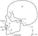
도 1a 및 도 1b는 일반적인 경우에 있어서 환자의 두개골(40), 상악골(10) 및 하악골(20)의 상대적인 관계를 예시하는 개략적인 도면이며, 여기서 상악골(10)은 두개골(40)에 고정 연결되어 있고, 하악골(20)은 악관절(30)을 통해 두개골(40)에 대해 움직일 수 있게 연결되어 있다. 또한, 환자의 상악골 치열궁(12) 및 하악골 치열궁(22)이 각각 상악골(10) 및 하악골(20)에 연결되어 있다. 상악골(10)과 하악골(20) 사이에 있는 환자의 악관절(30)이 최적의 위치에 있지 않으면, 이는 상악골(10)에 비해 하악골(20)이 앞으로 튀어나오게 하거나(도 1a) 또는 뒤로 들어가게 하는(도 1b) 결과를 초래할 수 있으며, 이에 따라 상악골 치열궁(12)과 하악골 치열궁(22)의 부정 교합이 발생할 수 있다. 결과적으로, 환자의 치아의 외관, 씹기와 같은 구강의 기능, 발음, 그리고 충치 및 치아의 마모와 같은 구강 건강 관련 문제에도 또한 악영향을 줄 수 있다.1A and 1B are schematic diagrams illustrating the relative relationship of a patient's
전술한 바와 같이, 본 발명의 목적은, 악교정 보정 장치를 제공하는 것이며, 구체적으로는 환자들이 두려움을 느끼는 수술 방법을 행하지 않으면서 악교정 보정을 달성하는 데 사용될 수 있고 환자가 제거 가능한 악교정 보정 장치를 제공하는 것이다.As described above, it is an object of the present invention to provide an orthodontic correction device, and more particularly, to a patient which can be used to achieve orthodontic correction without having to perform a fearful surgical procedure, .
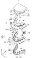
도 2는 본 발명의 일 실시예에 따른 악교정 보정 장치와 환자의 상악골 치열궁(12) 및 하악골 치열궁(22)의 상대적인 관계를 예시하는 개략적인 도면이다. 도 2에 도시된 바와 같이, 상기 악교정 보정 장치는 주로 제1 리테이너(100), 제2 리테이너(200) 및 수 개의 탄성 부재(500)를 포함한다. 또한, 제1 리테이너(100) 상에 배치되는 수 개의 제1 브라켓(302), 제1 아치형 와이어(304), 및 제1 연결 부품(306)이 있으며, 제2 리테이너(200) 상에 배치되는 수 개의 제2 브라켓(402), 제2 아치형 와이어(404) 및 제2 연결 부품(406)이 있다.2 is a schematic diagram illustrating the relative relationship between the orthodontic correction device and a patient's maxillary
제1 리테이너(100)는, 서로 대향하는 제1 치아 수용 부분(R1) 및 제1 교합면(occlusal face; B1)을 갖는다. 또한, 제2 리테이너(200)는, 서로 대향하는 제2 치아 수용 부분(R2) 및 제2 교합면(occlusal face; B2)을 갖는다. 제1 교합면(B1)은 제2 교합면(B2)에 대응한다. 제1 치아 수용 부분(R1) 및 제2 치아 수용 부분(R2)은 각각 상악골 치열궁(12) 및 하악골 치열궁(22)을 수용하기 위한 수용 공간을 형성한다.The first retainer (100) has a first tooth receiving portion (R1) and a first occlusal face (B1) facing each other. Further, the
제1 리테이너(100) 및 제2 리테이너(200)는 제거 가능한 리테이너이며(또한 움직일 수 있는 리테이너로서 알려져 있음), 이에 따라 환자는 필요에 따라 상황을 감안하여 리테이너를 자유롭게 착용 또는 제거할 수 있고 또한 자신의 치아를 정상적으로 양치질할 수 있다는 것을 이해할 것이다. 일부 실시예에 있어서, 제1 리테이너(100) 및 제2 리테이너(200)는 열가소성 수지, 합성 수지 또는 구강 용례에서 사용하기에 적절한 다른 재료를 포함할 수 있다.The
도 2의 실시예에서 도시된 바와 같이, 제1 리테이너(100)는 또한 서로 대향하는 제1 좌측 볼면(100a) 및 제1 우측 볼면(100b)을 갖는다. 제1 브라켓(302)은 제1 좌측 볼면(100a) 및 제1 우측 볼면(100b) 상에 장착된다[예컨대, 제1 좌측 볼면(100a) 및 제1 우측 볼면(100b)은 각각 이들 볼면 상에 5개의 제1 브라켓(302)을 갖추고 있음]. 제1 아치형 와이어(304)들[예컨대, 2개의 제1 아치형 와이어(304)]은 제1 좌측 볼면(100a) 및 제1 우측 볼면(100b) 상에서 제1 브라켓(302)을 통과하며, 제1 브라켓(302)에 의해 고정된다. 또한, 제1 아치형 와이어(304)들에는 각각 제1 연결 부품(306)이 부착되어 있으며[예컨대, 4개의 제1 연결 부품(306)이 부착되어 있고, 각각의 제1 연결 부품은 후크 구조(hook structure)를 나타냄], 제1 연결 부품(306)은 제1 브라켓(302)들 사이에 위치하게 된다.As shown in the embodiment of Fig. 2, the
마찬가지로, 제2 리테이너(200)는 또한 서로 대향하는 제2 좌측 볼면(200a) 및 제2 우측 볼면(200b)을 가지며, 여기서 제2 좌측 볼면(200a)은 제1 리테이너(100)의 제1 좌측 볼면(100a)에 대응하고, 제2 우측 볼면(200b)은 제1 리테이너(100)의 제1 우측 볼면(100b)에 대응한다. 제2 브라켓(402)은 제2 좌측 볼면(200a) 및 제2 우측 볼면(200b) 상에 장착된다[예컨대, 제2 좌측 볼면(200a) 및 제2 우측 볼면(200b)은 각각 이들 볼면 상에 5개의 제2 브라켓(402)을 갖추고 있음]. 제2 아치형 와이어(404)들[예컨대, 2개의 제2 아치형 와이어(404)]은 각각 제2 좌측 볼면(200a) 및 제2 우측 볼면(200b) 상에서 제2 브라켓(402)을 통과하며, 제2 브라켓(402)에 의해 고정된다. 또한, 제2 아치형 와이어(404)들에는 각각 제2 연결 부품(406)이 부착되어 있으며[예컨대, 4개의 제2 연결 부품(406)이 부착되어 있고, 각각의 제2 연결 부품은 후크 구조(hook structure)를 나타냄], 제2 연결 부품(406)은 제2 브라켓(402)들 사이에 위치하게 된다.Similarly, the
일부 실시예에 있어서, 제1 브라켓(302) 및 제2 브라켓(402)은 스테인레스 강, Ni-Ti 합금 또는 가소성 세라믹 재료를 포함할 수 있다. 제1 아치형 와이어(304) 및 제2 아치형 와이어(404)뿐만 아니라 제1 연결 부품(306) 및 제2 연결 부품(406)은 스테인레스 강 또는 Ni-Ti 합금 재료를 포함할 수 있다.In some embodiments, the
도 2에 도시된 바와 같이, 탄성 부재(500)는 제1 좌측 볼면(100a) 상의 제1 연결 부품(306)(즉, 제1 좌측 연결 부품)을 제2 좌측 볼면(200a) 상의 제2 연결 부품(406)(즉, 제2 좌측 연결 부품)에 결합시키는 데 사용되며, 제1 우측 볼면(100b) 상의 제1 연결 부품(306)(즉, 제1 우측 연결 부품)을 제2 우측 볼면(200b) 상의 제2 연결 부품(406)(즉, 제2 우측 연결 부품)에 결합시키는 데 사용되고[예컨대, 제1 리테이너(100) 및 제2 리테이너(200)의 좌측 볼면 및 우측 볼면은 각각 3개의 탄성 부재(500)와 함께 구성됨], 이에 따라 탄성 부재(500)의 탄성력은, 제1 리테이너(100)에 대해 (Y축과 Z축 사이의 방향을 따라) 후방 상향으로 이동하도록 또는 (-Y축과 -Z축 사이의 방향을 따라) 전방 하향으로 이동하도록 제2 리테이너(200)를 구동시킬 수 있다. 이에 따라, 제2 리테이너(200)에 연결되는 환자의 하악골(20)과 제1 리테이너(100)에 연결되는 환자의 상악골(10) 사이의 상대적인 위치가 조정될 수 있고, 이에 따라 악교정 보정이 달성된다.2, the
제1 리테이너(100) 및 제2 리테이너(200)의 대응하는 볼면들 상에서 제1 연결 부품(306) 및 제2 연결 부품(406)을 탄성 부재(500)로 결합시키는 방법이 변경되면, 이에 따라 제1 리테이너(100)에 대해 (Y축과 Z축 사이의 방향을 따라) 후방 상향으로 이동하도록 또는 (-Y축과 -Z축 사이의 방향을 따라) 전방 하향으로 이동하도록 제2 리테이너(200)를 구동시키는 탄성력이 발생될 수 있다는 것을 주의해야 한다. 일부 실시예에 있어서, 탄성 부재(500)들은 고무 밴드 또는 Ni-Ti 합금 재료로 제조되는 스프링 코일과 같은 환형체일 수 있으며, 동일한 탄성력 또는 상이한 탄성력을 나타낸다.If the manner in which the first connecting
구체적으로, 제1 리테이너(100) 및 제2 리테이너(200)의 좌측 볼면 및 우측 볼면 상에 배치되는 탄성 부재(500)의 개수 및 탄성력이 서로 매칭(matching)될 때, 제1 리테이너(100) 및 제2 리테이너(200)의 좌측 볼면 및 우측 볼면은 균일한 힘을 견딜 수 있게 되며, 이에 따라 제2 리테이너(200)에 연결되는 하악골(20)이 환자의 입의 가상의 중심 축선(C)(도 2의 Y축에 대해 평행임)을 따라 제1 리테이너(100)에 연결된 상악골(10)에 대해 회전하지 못하게 되고, 결과적으로 단지 도 2에서의 Y축과 Z축 사이의 방향을 따라서만 또는 -Y축과 -Z축 사이의 방향을 따라서만 하악골(20)과 상악골(10) 사이의 상대적인 운동이 이루어지게 된다. 그러나, 일부 실시예에 있어서, 제1 리테이너(100) 및 제2 리테이너(200)의 좌측 볼면 및 우측 볼면 상에 배치되는 탄성 부재(500)의 개수 및 탄성력이 매칭되지 않을 수도 있으며, 이에 따라 다양한 환자들의 다양한 상황을 수용할 수 있다.Specifically, when the number and the elastic force of the
더욱이, 제1 브라켓(302) 및 제2 브라켓(402)의 위치 및 개수, 제1 아치형 와이어(304) 및 제2 아치형 와이어(404)의 개수 및 길이, 제1 (좌측/우측) 연결 부품(306) 및 제2 (좌측/우측) 연결 부품(406)의 위치 및 개수, 그리고 탄성 부재(500)의 개수는 도 2의 실시예의 것으로 한정되지 않으며, 오히려 요구사항에 따라 조정될 수 있다.Further, the number and length of the
도 2를 더 참고하면, 악교정 보정 장치는 제1 리테이너(100)의 제1 좌측 볼면(100a)과 제1 우측 볼면(100b) 사이의 입술면(100c) 상에 고정 장착되는 제1 중앙 연결 부품(308)(예컨대, 후크 구조)을 더 포함할 수 있다. 또한, 적어도 하나의 탄성 부재(500)는, 제1 중앙 연결 부품(308)과 제1 좌측 볼면(100a) 또는 제1 우측 볼면(100b) 상의 제1 연결 부품(306)을 결합시키는 데 사용될 수 있으며, 이후 제1 연결 부품(306)과 제2 리테이너(200) 상의 대응하는 제2 연결 부품(406)[제1 연결 부품(306)에 대해 후방의 위치에 있음]을 결합시키는 데 사용될 수 있고, 이에 따라 탄성 부재(500)의 탄성력은 도 2에 도시된 바와 같이 X방향을 따라 또는 -X방향을 따라 제1 리테이너(100)에 대해 이동하도록 제2 리테이너(200)를 구동시킬 수 있으므로, 상악골(10)과 하악골(20) 사이의 수평방향 비대칭성이 교정되게 된다. 마찬가지로, 도 2에 도시된 바와 같이, 악교정 보정 장치는 제2 리테이너(200)의 제2 좌측 볼면(200a)과 제2 우측 볼면(200b) 사이의 입술면(200c) 상에 고정 장착되는 제2 중앙 연결 부품(408)(예컨대, 후크 구조)을 더 포함할 수 있다. 또한, 적어도 하나의 탄성 부재(500)는, 제2 중앙 연결 부품(408)과 제2 좌측 볼면(200a) 또는 제2 우측 볼면(200b) 상의 제2 연결 부품(406)을 결합시키는 데 사용될 수 있으며, 이후 제2 연결 부품(406)과 제1 리테이너(100) 상의 대응하는 제1 연결 부품(306)[제2 연결 부품(406)에 대해 후방의 위치에 있음]을 결합시키는 데 사용될 수 있고, 이에 따라 상악골(10)과 하악골(20) 사이의 수평방향 비대칭성이 교정되게 된다.2, the orthognathic correction device includes a first central connecting
일부 실시예에 있어서, 제1 중앙 연결 부품(308) 및 제2 중앙 연결 부품(408)의 재료 및 조립 방법은 제1 연결 부품(306) 및 제2 연결 부품(406)의 재료 및 조립 방법과 동일하다.In some embodiments, the materials and methods of assembly of the first central connecting
도 3a는 환자의 상악골 치열궁 상에 착용되어 있는, 본 발명의 일 실시예에 따른 제1 리테이너(100)를 예시하는 개략적인 도면이다. 도 3b는 환자의 하악골 치열궁 상에 착용되어 있는, 본 발명의 일 실시예에 따른 제2 리테이너(200)를 예시하는 개략적인 도면이다.FIG. 3A is a schematic view illustrating a
도 3a 및 도 3b에 도시된 바와 같이, 제1 리테이너(100) 및 제2 리테이너(200)가 상악골 치열궁 및 하악골 치열궁 상에 착용되어 있을 때, 이들 리테이너는 상악골 치열궁 및 하악골 치열궁의 전체 크라운(crown)을 실질적으로 커버(cover)하게 된다는 것을 이해할 것이다. 보다 구체적으로, 제1 리테이너(100) 및 제2 리테이너(200)는 상악골 치열궁 및 하악골 치열궁의 언더컷 구조(undercut structure)에 따라 구성되며, 이에 따라 제1 리테이너(100) 및 제2 리테이너(200)는 상악골 치열궁 및 하악골 치열궁의 전체 크라운을 동형으로(conformably) 커버하게 되므로, 상악골 치열궁 및 하악골 치열궁과 맞물리는 제1 리테이너(100) 및 제2 리테이너(200)의 유지를 강화시킨다. 따라서, 악교정 보정 중에 상악골 치열궁 및 하악골 치열궁으로부터 제1 리테이너(100) 및 제2 리테이너(200)가 쉽게 분리되는 것을 방지할 수 있다.As shown in FIGS. 3A and 3B, when the
도 3a를 참고하면, 두꺼운 부분(102) 및 수 개의 두꺼운 부분(104)이 제1 리테이너(100)의 제1 교합면(B1) 상에 형성된다. 구체적으로, 두꺼운 부분(102)의 위치는 상악골 치열궁(도 2 참고)의 2개의 앞니(12A) 및 2개의 옆쪽 앞니(12B)에 대응하며, 두꺼운 부분(104)들의 위치는 각각 상악골 치열궁(도 2 참고)의 (좌측 및 우측) 송곳니(12C), 제1 소구치(12D) 및 제2 소구치(12E)에 각각 대응한다. 더욱이, 두꺼운 부분(102)은, 앞니(12A 및 12B)의 상부로부터 시작하여 점차적으로 구개 면(palatal side; T)을 향해 내려가는 안내면을 형성하며, 두꺼운 부분(104)은 또한 두꺼운 부분(104)의 가장 두꺼운 부분[송곳니(12C), 제1 소구치(12D) 및 제2 소구치(12E)의 중심에 대응함]으로부터 시작하여 점차적으로 두꺼운 부분(104)의 가장 얇은 부분(전술한 치아의 이웃한 위치에 위치함)을 향해 내려가는 안내면을 형성한다. 두꺼운 부분(102) 및 두꺼운 부분(104)의 안내면들은 평평할 수도 있고 곡선형일 수도 있다.3A, a
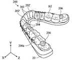
마찬가지로, 도 3b를 참고하면, 수 개의 두꺼운 부분(204)이 제2 리테이너(200)의 제2 교합면(B2) 상에 형성된다. 구체적으로, 두꺼운 부분(204)의 위치는 하악골 치열궁(도 2 참고)의 (좌측 및 우측) 제1 소구치(22A) 및 제2 소구치(22B)에 각각 대응한다. 두꺼운 부분(204)의 가장 두꺼운 부분은 제1 소구치(22A) 및 제2 소구치(22B)의 중심에 대응한다.3B, several
본 개시내용에서 사용되는 용어 "두꺼운 부분"은, 예컨대 제1 교합면(B1)의 영역이 두꺼운 부분(102 및 104)에 대응되며, 각각의 상기 두꺼운 부분은 제1 교합면(B1)의 다른 영역(두꺼운 부분이 없는 영역)보다 더 두껍고, 제2 교합면(B2)의 영역이 두꺼운 부분(104)에 대응하며, 각각의 두꺼운 부분은 제2 교합면(B2)의 다른 영역(두꺼운 부분이 없는 영역)보다 더 두껍다는 것을 나타낸다는 것에 주의하라.The term "thick part" as used in this disclosure corresponds, for example, to the area of the first occlusal surface B1 corresponding to the
일부 실시예에 있어서, 제1 리테이너(100) 및 두꺼운 부분(102 및 104)은 하나의 부품으로 일체로 형성될 수 있다. 대안으로, 두꺼운 부분(102 및 104)은, 합성 수지, 글라스 이오노머(glass ionomer), 또는 구강 용례에서 사용하기에 적합한 다른 내마모성 재료로 형성된 이후에 제1 리테이너(100)의 제1 교합면(B1)에 접합될 수 있다. 마찬가지로, 제2 리테이너(200) 및 두꺼운 부분(204)은 하나의 부품으로 일체로 형성될 수 있다. 대안으로, 두꺼운 부분(204)은, 합성 수지, 글라스 이오노머(glass ionomer), 또는 구강 용례에서 사용하기에 적합한 다른 내마모성 재료로 형성된 이후에 제2 리테이너(200)의 제2 교합면(B2)에 접합될 수 있다.In some embodiments, the
환자가 앞서 설명된 바와 같은 악교정 보정 장치를 착용하고 있을 때, 그리고 제1 리테이너(100)의 제1 교합면(B1)이 제2 리테이너(200)의 제2 교합면(B2)과 접촉하고 있을 때, 하악골 치열궁의 2개의 앞니 그리고 2개의 옆쪽 앞니에 대응하는 제2 리테이너(200)의 수 개의 서브유닛(subunit)(202 및 202')(도 2 및 도 3b 참고)은 제1 리테이너(100) 상의 두꺼운 부분(102)(도 3a 참고)과 접촉할 수 있으며, 제2 리테이너(200) 상의 두꺼운 부분(204)(도 3b 참고)은 제1 리테이너(100) 상의 두꺼운 부분(104)(도 3a 참고)과 접촉할 수 있다.When the patient is wearing the orthodontic correction device as described above and the first occlusal surface B1 of the
도 4는 본 발명의 일 실시예에 따른 악교정 보정 장치의 작동 원리를 예시하는 개략적인 도면이다. 전술한 구조적 구성을 채용하면, 제1 리테이너(100)의 제1 교합면(B1)이 제2 리테이너(200)의 제2 교합면(B2)과 접촉할 때, 제1 교합면(B1) 상의 두꺼운 부분(102 및 104)은 안내 블록으로서 사용될 수 있으며, 제2 교합면(B2) 상의 두꺼운 부분(204) 및 서브유닛(202, 202')은 안내 블록(102 및 104)의 안내면과 접촉할 수 있다(도시를 단순화하기 위해, 오직 하나의 안내면 및 하나의 접촉점만이 도 4에 도시되어 있음). 이러한 상황에서, 탄성 부재(500)(도 2 참고)에 의해 가해지는 탄성력은, 제1 리테이너(100)에 대해 안내면을 따라 (도 4에 화살표로 표시되어 있는 바와 같이) 슬라이딩하도록 제2 리테이너(200)를 구동시킬 수 있으며, 이에 따라 제2 리테이너(200)에 연결되는 하악골(20)이 제1 리테이너(100)에 연결되는 상악골(10)에 대해 이동하도록 하고 악관절(30)이 다시 적절한 위치로 옮겨지게 하여, 악교정 보정을 달성한다.4 is a schematic diagram illustrating the operating principle of the orthodontic correction apparatus according to an embodiment of the present invention. When the first occlusal surface B1 of the
탄성 부재(500)의 탄성력에 의해 제1 리테이너(100)에 대해 (Y축과 Z축 사이의 방향을 따라) 후방 상향으로 이동하도록 제2 리테이터(200)가 구동될 때, 환자의 하악골(20)이 도 1a에 도시된 바와 같이 상악골(10)에 비해 앞으로 튀어나와 있는 상황이 개선될 수 있다. 반대로, 탄성 부재(500)의 탄성력에 의해 제1 리테이너(100)에 대해 (-Y축과 -Z축 사이의 방향을 따라) 전방 하향으로 이동하도록 제2 리테이터(200)가 구동될 때, 환자의 하악골(20)이 도 1b에 도시된 바와 같이 상악골(10)에 비해 뒤로 들어가 있는 상황이 개선될 수 있다.When the
전술한 실시예에서 안내 블록 및 안내면은 제1 리테이너(100)의 제1 교합면(B1) 상에 형성되지만, 이들 안내 블록 및 안내면은 또한 제2 리테이너(200)의 제2 교합면(B2) 상에 형성될 수 있다.The guide block and the guide surface are formed on the first occlusal surface B1 of the
제1 리테이너(100)의 두꺼운 부분(102, 104)의 위치 및 개수 그리고 제2 리테이너(200)의 두꺼운 부분(204)의 위치 및 개수는 도 3a 및 도 3b의 실시예에 제시된 위치 및 개수로 한정되지 않고, 오히려 다양한 환자의 다양한 상태에 따라 조정될 수 있다.The positions and the number of the
더욱이, 환자의 하악골(20)이 상악골(10)에 비해 앞으로 돌출되어 있는 경우, 상악골 치열궁(12)의 제2 어금니(12F)는 흔히 하악골 치열궁(22)의 제2 어금니(12C)를 방해할 가능성이 있으며(도 1a 참고), 결과적으로 하악골 치열궁(22) 상에 배치되는 제2 리테이너(200)는 상악골 치열궁(12) 상에 배치되는 제1 리테이너(100)와 결합될 때 달라붙어 꼼짝 못하게 되는 결과를 초래하고, 이에 따라 하악골(20)은 악교정 보정 중에 상악골(10)에 대해 (Y축과 Z축 사이의 방향을 따라) 후방 상향으로 원활하게 이동할 수 없게 된다.The
도 3a 및 도 3b를 참고하면, 이에 따라, 제1 리테이너(100)의 제1 교합면(B1)은 상악골 치열궁(12)의 좌측 제2 어금니(12F) 및 우측 제2 어금니(12F)를 노출시키기 위해 상기 제1 교합면 상에 형성된 2개의 개구(106)를 구비할 수 있으며, 제2 리테이너(200)의 제2 교합면(B2)에는 또한 상기 제2 교합면 상에서 제1 리테이너(100)의 개구(106)들에 각각 대응하는 2개의 스페이서(206)가 형성되어 있을 수 있다. 제1 리테이너(100)의 제1 교합면(B1)이 제2 리테이너(200)의 제2 교합면(B2)과 접촉할 때, 스페이서(206)는 개구(106)를 통해 제2 송곳니(12F)와 이웃할 수 있어 제1 리테이너(100)와 제2 리테이너(200) 사이의 공간이 넓어지게 되며, 이에 따라 제2 리테이너(200)가 제1 리테이너(100)에 대해 달라붙어 꼼짝 못하게 되는 것을 방지한다는 것을 이해해야 한다. 따라서, 본 실시예의 악교정 보정 장치는 제2 리테이너(200)에 연결되는 하악골(20)과 제1 리테이너(100)에 연결되는 상악골(10) 사이의 상대적인 위치를 원할하게 조절하여 악교정 보정을 달성할 수 있다. 또한, 본 실시예의 악교정 보정 장치는 하악골(20)의 회전도 역시 유발할 수 있도록 구현된다.3A and 3B, the first occlusal surface B1 of the
본 실시예에 있어서, 스페이서(206)는 또한 두꺼운 부분으로서 간주될 수 있으며, 그 제조 방법은 두꺼운 부분(204)의 제조 방법과 동일하다. 더욱이, 일부 실시예에 있어서, 스페이서(206) 및 개구(106)의 위치 및 개수가 또한 조정될 수 있다. 일부 실시예에 있어서, 제1 교합면(B1) 또는 제2 교합면(B2) 상의 개구가 또한 생략될 수도 있다.In this embodiment, the
비록 전술한 실시예에 있어서 악교정 보정 장치는 제1 리테이너(100) 및 제2 리테이너(200)를 포함하고 있지만, 일부 실시예에서의 악교정 보정 장치는 또한 상악골 치열궁 또는 하악골 치열궁 상에 제거 가능하게 착용되도록 구성되는 단일 리테이너[제1 리테이너(100) 또는 제2 리테이너(200)]를 포함할 수도 있다. 이러한 경우에 있어서, 또한 리테이너 없이 다른 치열궁의 좌측 볼면 및 우측 볼면 상에 적어도 2개의 연결 부품(즉, 좌측 연결 부품 및 우측 연결 부품)이 있을 수 있으며(예컨대, 상악골 치열궁 상에 리테이너가 착용되어 있다면, 하악골 치열궁의 좌측 볼면 및 우측 볼면 상에 적어도 2개의 연결 부품이 고정되어 있을 수 있고, 반대로 하악골 치열궁 상에 리테이너가 착용되어 있다면, 상악골 치열궁의 좌측 볼면 및 우측 볼면 상에 적어도 2개의 연결 부품이 고정될 수 있음), 리테이너 없이 이러한 치열궁의 교합면에는 그 위에 두꺼운 부분(안내 블록)이 추가로 형성되어 있을 수 있다. 따라서, 상악골에 대해 이동하도록 하악골을 구동시키기 위해 탄성 부재를 사용하여 리테이너 없이 치열궁 상의 연결 부품 및 리테이너 상의 연결 부품을 결합시킴으로써, 악교정 보정의 목적이 또한 달성될 수 있다. 더욱이, 리테이너 없이 치열궁은 또한 좌측 볼면과 우측 볼면 사이에서 그 입술면 상에 중앙 연결 부품을 구비할 수 있으며, 상기 중앙 연결 부품은 이웃한 좌측 볼면 또는 우측 볼면 상의 연결 부품에 결합될 수 있고, 이후 탄성 부재에 의해 다른 치열궁 상에 착용된 리테이터의 대응하는 좌측 볼면 또는 우측 볼면 상의 연결 부품에 결합될 수 있으며, 이에 따라 앞서 설명된 바와 같이 상악골(10)과 하악골(20) 사이의 수평방향 비대칭이 교정된다.Although the orthognathic correction device in the above embodiment includes the
전술한 실시예(도 2 참고)에서, 제1 리테이너(100)의 제1 치아 수용 부분(R1)은 상악골 치열궁(12)의 모든 치아(즉, 상악골 치아)를 감싸도록 성형되며, 제2 리테이너(200)의 제2 치아 수용 부분(R2)은 하악골 치열공(22)의 모든 치아(즉, 하악골 치아)를 감싸도록 성형되고, 제1 치아 수용 부분(R1)은 또한 상악골 치열궁(12)의 (상악골 치아의) 일부를 감싸도록 성형될 수 있으며, 제2 치아 수용 부분(R2)은 또한 하악골 치열궁(22)의 (하악골 치아의) 일부를 감싸도록 성형될 수 있다.2), the first tooth receiving portion R1 of the
더욱이, 도 5a 및 도 5b를 참고하면, 도 5a는 환자의 상악골 치열궁 상에 착용되어 있는, 본 발명의 다른 실시예에 따른 제1 리테이너(100')를 예시하는 개략적인 도면이며, 도 5b는 환자의 하악골 치열궁 상에 착용되어 있는, 본 발명의 다른 실시예에 따른 제2 리테이너(200')를 예시하는 개략적인 도면이다. 도 5a 및 도 5b에 도시된 바와 같이, 제1 리테이너(100')는 또한 도 3a의 실시예에서와 같이 거의 전체를 커버하는 대신, 상악골 치열궁(12)의 교합면(O1)을 노출시킬 수 있고, 제2 리테이너(200')는 또한 도 3b의 실시예에서와 같이 거의 전체를 커버하는 대신, 하악골 치열궁(22)의 교합면(O2)을 노출시킬 수 있다. 제1 리테이너(100')의 볼면 상의 제1 연결 부품(306)을 제2 리테이너(200')의 볼면 상의 제2 연결 부품(406)에 결합시키기 위해 앞서 설명된 수 개의 탄성 부재(500)(도 2 참고)를 이용함으로써, 악교정 보정이 또한 달성될 수 있다는 것을 이해해야 한다.5A and 5B, FIG. 5A is a schematic view illustrating a first retainer 100 'according to another embodiment of the present invention, which is worn on the maxillary arch of the patient, and FIG. 5B Is a schematic view illustrating a second retainer 200 'according to another embodiment of the present invention, which is worn on a mandibular arch of a patient. As shown in Figures 5A and 5B, the first retainer 100 'may also be configured to expose the occlusal surface O1 of the maxillary
도 5a 및 도 5b에 도시된 바와 같이, 또한 제1 리테이너(100')의 설부면(lingual surface) 상에 적어도 하나의 제1 설부 연결 부품(lingual connection part; 306')이 고정되어 있을 수 있으며, 또한 제2 리테이너(200')의 설부면 상에 적어도 하나의 제2 설부 연결 부품(406')이 고정되어 있을 수 있다. 제1 설부 연결 부품(306') 및 제2 설부 연결 부품(406')은 도 2의 실시예에서의 제1 연결 부품(306) 및 제2 연결 부품(406)과 동일한 재료로 되어 있을 수 있다. 본 실시예(도 5a 및 도 5b 참고)에 있어서, 제1 리테이너(100'), 제1 연결 부품(306) 및 제1 설부 연결 부품(306')는 (예컨대, 금속 몰딩에 의해) 하나의 부품으로 일체로 형성될 수 있으며, 제2 리테이너(200'), 제2 연결 부품(406) 및 제2 설부 연결 부품(406')은 (예컨대, 금속 몰딩에 의해) 하나의 부품으로 일체로 형성될 수 있지만, 본 발명은 이로써 한정되지 않는다.As shown in FIGS. 5A and 5B, at least one first lingual connection part 306 'may also be fixed on the lingual surface of the first retainer 100' , And at least one second tongue connecting part 406 'may be fixed on the tongue face of the second retainer 200'. The first tongue connecting part 306 'and the second tongue connecting part 406' may be made of the same material as the first connecting
본 발명의 실시예 및 그 장점이 상세하게 설명되었지만, 첨부된 청구범위에 의해 한정되는 바와 같은 본 발명의 사상 및 범위로부터 벗어나지 않으면서 상기 실시예에서 다양한 변경, 대체 및 변형이 행해질 수 있다는 것을 이해해야 할 것이다. 예를 들면, 당업자는, 본 발명의 범위에 여전히 속하도록 하면서도 본원에서 설명되는 다수의 특징, 기능, 프로세스 및 재료가 변경될 수 있다는 것을 용이하게 이해할 수 있을 것이다. 더욱이, 본 출원의 범위를 본 명세서에서 설명된 프로세스, 기계, 제조, 물질의 조성, 수단, 방법 및 단계에 관한 특정 실시예로 한정하려는 의도가 아니다. 당업자는, 본 발명의 개시내용으로부터, 본원에서 설명되는 대응하는 실시예와 실질적으로 동일한 기능을 수행하거나 또는 실질적으로 동일한 결과를 달성하는 것으로서, 현재 존재하거나 추후 개발될 프로세스, 기계, 제조, 물질의 조성, 수단, 방법 또는 단계가 본 발명에 따라 이용될 수 있다는 것을 용이하게 이해할 수 있을 것이다. 이에 따라, 첨부된 청구범위는 이러한 프로세스, 기계, 제조, 물질의 조성, 수단, 방법 또는 단계를 그 범위에 포함하도록 의도된 것이다. 추가적으로, 각각의 청구항은 개별적인 실시예를 구성하며, 다양한 청구범위 및 실시예의 조합이 본 개시내용의 범위에 속한다.While the embodiments and advantages of the invention have been described in detail, it should be understood that various changes, substitutions and alterations can be made in the embodiments without departing from the spirit and scope of the invention as defined by the appended claims. something to do. For example, those skilled in the art will readily understand that many features, functions, processes and materials described herein may be varied while still falling within the scope of the present invention. Moreover, the scope of the present application is not intended to be limited to the specific embodiments with respect to the process, machine, manufacture, composition of matter, means, methods and steps set forth herein. Those skilled in the art will readily derive, from the teachings of the present invention, that a process, machine, manufacture, or article of manufacture presently or later to be developed, which performs substantially the same function or attains substantially the same result as the corresponding embodiment described herein Compositions, means, methods, or steps may be utilized in accordance with the invention. Accordingly, the appended claims are intended to cover such process, machine, manufacture, composition of matter, means, method, or step. In addition, each claim constitutes a separate embodiment, and the various claims and combinations of embodiments fall within the scope of the present disclosure.
Claims (20)
Translated fromKorean환자의 상악골 치열궁(maxillary dental arch) 상에 제거 가능하게 착용되도록 구성되며, 적어도 하나의 제1 좌측 연결 부품이 그 위에 고정되는 제1 좌측 볼면(left buccal surface) 그리고 적어도 하나의 제1 우측 연결 부품이 그 위에 고정되는 제1 우측 볼면을 갖는 것인 제1 리테이너;
환자의 하악골 치열궁(mandibular dental arch) 상에 제거 가능하게 착용되도록 구성되며, 적어도 하나의 제2 좌측 연결 부품이 그 위에 고정되는 제2 좌측 볼면 그리고 적어도 하나의 제2 우측 연결 부품이 그 위에 고정되는 제2 우측 볼면을 갖는 것인 제2 리테이너;
제1 좌측 연결 부품을 제2 좌측 연결 부품에 결합시키도록 구성되는 적어도 하나의 탄성 부재, 그리고 제1 우측 연결 부품을 제2 우측 연결 부품에 결합시키도록 구성되는 적어도 하나의 탄성 부재
를 포함하며, 상기 탄성 부재는 제1 리테이너에 대해 움직이도록 제2 리테이너를 구동시켜, 제1 리테이너 및 제2 리테이너가 각각 상악골 치열궁 및 하악골 치열궁 상에 유지될 때 환자의 상악골과 하악골 사이의 상대적인 위치를 조절하도록 하고,
상기 제2 리테이너는 제2 교합면을 더 가지며, 적어도 하나의 스페이서(spacer)가 상기 제2 교합면에 형성되고, 제1 리테이너는 제1 교합면을 더 가지며, 상악골 치열궁의 적어도 하나의 상악골 치아를 노출시키기 위해 적어도 하나의 개구가 상기 제1 교합면 상에 형성되고, 제1 교합면이 제2 교합면과 접촉할 때, 상기 스페이서는 상기 개구를 통해 상악골 치아와 이웃하여, 상악골 치아를 상방으로 밀어냄으로써, 제1 리테이너와 제2 리테이너 사이의 공간을 넓히는 것인 악교정 보정 장치.As the orthognathic correction device,
A first left buccal surface configured to be removably mounted on a maxillary dental arch of a patient and having at least one first left connecting part fixed thereon and at least one first right connecting A first retainer having a first right side surface on which the component is secured;
A second left side surface configured to be removably mounted on a mandibular dental arch of a patient and having at least one second left connecting part fixed thereon and at least one second right side connecting part A second retainer having a second right-side ball surface;
At least one resilient member configured to couple the first left connecting component to the second left connecting component and at least one resilient member configured to couple the first right connecting component to the second right connecting component,
Wherein the elastic member drives the second retainer to move relative to the first retainer such that when the first retainer and the second retainer are respectively retained on the maxillary arches and mandibular arches, The relative position is adjusted,
Wherein the second retainer further has a second occlusal surface, at least one spacer is formed on the second occlusal surface, the first retainer further has a first occlusal surface, at least one maxillary bone tooth of the maxillary dental arch Wherein at least one opening is formed on the first occlusal surface and when the first occlusal surface contacts the second occlusal surface, the spacer is adjacent to the maxillary tooth via the opening, , Thereby widening the space between the first retainer and the second retainer.
상기 제2 리테이너는 입술면을 더 가지며, 제2 중앙 연결 부품이 상기 입술면 상에 고정되고, 상기 악교정 보정 장치는, 제2 중앙 연결 부품을 제2 좌측 연결 부품에 그리고 제1 좌측 연결 부품에 결합시키도록 구성되거나 혹은 제2 중앙 연결 부품을 제2 우측 연결 부품에 그리고 제1 우측 연결 부품에 결합시키도록 구성되는 적어도 하나의 탄성 부재를 더 포함하여, 환자의 상악골과 하악골 사이의 수평방향 비대칭이 교정되도록 하는 것인 악교정 보정 장치.The method according to claim 1,
Wherein the second retainer further has a lipsurface and a second central connecting part is fixed on the lipsurface and the orthognathic correction device is configured to apply the second central connecting part to the second left connecting part and to the first left connecting part Further comprising at least one resilient member configured to engage the second central connecting part or to couple the second central connecting part to the second right connecting part and to the first right connecting part such that horizontal asymmetry between the maxilla and mandible of the patient Is corrected.
2. The orthognathic correction apparatus according to claim 1, wherein the second retainer further has a lingual surface, and at least one second tongue connecting part is fixed to the tongue surface.
Applications Claiming Priority (4)
| Application Number | Priority Date | Filing Date | Title |
|---|---|---|---|
| CN201510135110.3 | 2015-03-26 | ||
| CN201510135110 | 2015-03-26 | ||
| CN201610159772.9ACN105997274B (en) | 2015-03-26 | 2016-03-21 | orthodontic device |
| CN201610159772.9 | 2016-03-21 |
Publications (2)
| Publication Number | Publication Date |
|---|---|
| KR20160115854A KR20160115854A (en) | 2016-10-06 |
| KR101927582B1true KR101927582B1 (en) | 2018-12-10 |
Family
ID=57082809
Family Applications (1)
| Application Number | Title | Priority Date | Filing Date |
|---|---|---|---|
| KR1020160036708AExpired - Fee RelatedKR101927582B1 (en) | 2015-03-26 | 2016-03-28 | Orthognathic correction device and orthognathic correction method |
Country Status (4)
| Country | Link |
|---|---|
| JP (1) | JP6247328B2 (en) |
| KR (1) | KR101927582B1 (en) |
| CN (1) | CN105997274B (en) |
| TW (2) | TWI569781B (en) |
Families Citing this family (57)
| Publication number | Priority date | Publication date | Assignee | Title |
|---|---|---|---|---|
| JP3233861B2 (en) | 1996-10-31 | 2001-12-04 | 住友電装株式会社 | Insulated conductor pair and induction cable using this insulated conductor pair |
| US10537406B2 (en) | 2014-02-21 | 2020-01-21 | Align Technology, Inc. | Dental appliance with repositioning jaw elements |
| US9844424B2 (en) | 2014-02-21 | 2017-12-19 | Align Technology, Inc. | Dental appliance with repositioning jaw elements |
| US10449016B2 (en) | 2014-09-19 | 2019-10-22 | Align Technology, Inc. | Arch adjustment appliance |
| US10504386B2 (en) | 2015-01-27 | 2019-12-10 | Align Technology, Inc. | Training method and system for oral-cavity-imaging-and-modeling equipment |
| US11931222B2 (en) | 2015-11-12 | 2024-03-19 | Align Technology, Inc. | Dental attachment formation structures |
| US11554000B2 (en) | 2015-11-12 | 2023-01-17 | Align Technology, Inc. | Dental attachment formation structure |
| US11103330B2 (en) | 2015-12-09 | 2021-08-31 | Align Technology, Inc. | Dental attachment placement structure |
| US11596502B2 (en) | 2015-12-09 | 2023-03-07 | Align Technology, Inc. | Dental attachment placement structure |
| WO2017218947A1 (en) | 2016-06-17 | 2017-12-21 | Align Technology, Inc. | Intraoral appliances with sensing |
| US10383705B2 (en) | 2016-06-17 | 2019-08-20 | Align Technology, Inc. | Orthodontic appliance performance monitor |
| CA3030676A1 (en) | 2016-07-27 | 2018-02-01 | Align Technology, Inc. | Intraoral scanner with dental diagnostics capabilities |
| CN117257492A (en) | 2016-11-04 | 2023-12-22 | 阿莱恩技术有限公司 | Method and apparatus for dental imaging |
| US11026831B2 (en) | 2016-12-02 | 2021-06-08 | Align Technology, Inc. | Dental appliance features for speech enhancement |
| EP3547952B1 (en) | 2016-12-02 | 2020-11-04 | Align Technology, Inc. | Palatal expander |
| AU2017366755B2 (en) | 2016-12-02 | 2022-07-28 | Align Technology, Inc. | Methods and apparatuses for customizing rapid palatal expanders using digital models |
| WO2018102770A1 (en) | 2016-12-02 | 2018-06-07 | Align Technology, Inc. | Force control, stop mechanism, regulating structure of removable arch adjustment appliance |
| US10548700B2 (en) | 2016-12-16 | 2020-02-04 | Align Technology, Inc. | Dental appliance etch template |
| US10779718B2 (en) | 2017-02-13 | 2020-09-22 | Align Technology, Inc. | Cheek retractor and mobile device holder |
| WO2018183358A1 (en) | 2017-03-27 | 2018-10-04 | Align Technology, Inc. | Apparatuses and methods assisting in dental therapies |
| US10613515B2 (en) | 2017-03-31 | 2020-04-07 | Align Technology, Inc. | Orthodontic appliances including at least partially un-erupted teeth and method of forming them |
| US11045283B2 (en) | 2017-06-09 | 2021-06-29 | Align Technology, Inc. | Palatal expander with skeletal anchorage devices |
| CN116942335A (en) | 2017-06-16 | 2023-10-27 | 阿莱恩技术有限公司 | Automatic detection of tooth type and eruption status |
| US10639134B2 (en) | 2017-06-26 | 2020-05-05 | Align Technology, Inc. | Biosensor performance indicator for intraoral appliances |
| US10885521B2 (en) | 2017-07-17 | 2021-01-05 | Align Technology, Inc. | Method and apparatuses for interactive ordering of dental aligners |
| CN111107806B (en) | 2017-07-21 | 2022-04-19 | 阿莱恩技术有限公司 | Jaw profile anchoring |
| EP4278957A3 (en) | 2017-07-27 | 2024-01-24 | Align Technology, Inc. | System and methods for processing an orthodontic aligner by means of an optical coherence tomography |
| CN110996842B (en) | 2017-07-27 | 2022-10-14 | 阿莱恩技术有限公司 | Tooth Staining, Transparency and Glazing |
| US12274597B2 (en) | 2017-08-11 | 2025-04-15 | Align Technology, Inc. | Dental attachment template tray systems |
| JP6649999B2 (en)* | 2017-08-14 | 2020-02-19 | 澄祥 洪 | Orthodontic appliance |
| US11116605B2 (en) | 2017-08-15 | 2021-09-14 | Align Technology, Inc. | Buccal corridor assessment and computation |
| US11123156B2 (en) | 2017-08-17 | 2021-09-21 | Align Technology, Inc. | Dental appliance compliance monitoring |
| US12171575B2 (en) | 2017-10-04 | 2024-12-24 | Align Technology, Inc. | Intraoral systems and methods for sampling soft-tissue |
| US10813720B2 (en) | 2017-10-05 | 2020-10-27 | Align Technology, Inc. | Interproximal reduction templates |
| CN111182851B (en)* | 2017-10-06 | 2022-05-13 | 3M创新有限公司 | Removable dental appliance including a jumper wire |
| CN111565668B (en) | 2017-10-27 | 2022-06-07 | 阿莱恩技术有限公司 | Substitute occlusion adjusting structure |
| CN111295153B (en)* | 2017-10-31 | 2023-06-16 | 阿莱恩技术有限公司 | Dental appliance with selective bite loading and controlled tip staggering |
| WO2019089782A1 (en)* | 2017-11-01 | 2019-05-09 | Align Technology, Inc. | Systems and methods for correcting malocclusions of teeth |
| CN119235481A (en) | 2017-11-01 | 2025-01-03 | 阿莱恩技术有限公司 | Automatic treatment planning |
| US11534974B2 (en) | 2017-11-17 | 2022-12-27 | Align Technology, Inc. | Customized fabrication of orthodontic retainers based on patient anatomy |
| US11219506B2 (en) | 2017-11-30 | 2022-01-11 | Align Technology, Inc. | Sensors for monitoring oral appliances |
| US11432908B2 (en) | 2017-12-15 | 2022-09-06 | Align Technology, Inc. | Closed loop adaptive orthodontic treatment methods and apparatuses |
| US10980613B2 (en) | 2017-12-29 | 2021-04-20 | Align Technology, Inc. | Augmented reality enhancements for dental practitioners |
| US10813727B2 (en) | 2018-01-26 | 2020-10-27 | Align Technology, Inc. | Diagnostic intraoral tracking |
| US11937991B2 (en) | 2018-03-27 | 2024-03-26 | Align Technology, Inc. | Dental attachment placement structure |
| EP3773320B1 (en) | 2018-04-11 | 2024-05-15 | Align Technology, Inc. | Releasable palatal expanders |
| TWI739054B (en)* | 2018-06-29 | 2021-09-11 | 財團法人工業技術研究院 | Positioning guidance method for tooth brackets and system thereof |
| US11049276B2 (en) | 2018-06-29 | 2021-06-29 | Industrial Technology Research Institute | Positioning guidance method and system for tooth brackets |
| US11534277B2 (en) | 2019-03-25 | 2022-12-27 | Align Technology, Inc. | Various structured supports for 3D printed aligners/mouth pieces |
| WO2021043129A1 (en)* | 2019-09-02 | 2021-03-11 | 杨幽幽 | Transparent correction teeth brace |
| JP6945113B1 (en)* | 2020-05-21 | 2021-10-06 | SheepMedical株式会社 | Orthodontic appliance manufacturing equipment and methods |
| CN114010347B (en)* | 2020-11-12 | 2024-06-04 | 上海交通大学医学院附属第九人民医院 | Self-fixing type individuation mandibular retainer and construction method thereof |
| CN112741705B (en)* | 2020-12-30 | 2024-09-24 | 重庆医科大学 | Hydrostatic jaw pad of finished product |
| CN113017869A (en)* | 2021-03-22 | 2021-06-25 | 深圳隐领科技有限公司 | Aesthetic tooth socket and preparation method and application thereof |
| JP2023127580A (en)* | 2022-03-01 | 2023-09-13 | 利彰 牛込 | orthodontic appliance |
| CN114983595B (en)* | 2022-06-15 | 2024-11-26 | 上海交通大学医学院附属第九人民医院 | Integrated post-orthognathic tooth and jaw stabilization device and design method thereof |
| TWI847941B (en)* | 2023-12-20 | 2024-07-01 | 梁師維 | Fixed device for ridge augmentation |
Citations (4)
| Publication number | Priority date | Publication date | Assignee | Title |
|---|---|---|---|---|
| US5683244A (en) | 1995-07-10 | 1997-11-04 | Truax; Lloyd H. | Dental appliance to correct malocclusion |
| US20100307511A1 (en) | 2007-04-23 | 2010-12-09 | Meade Thomas E | Mandibular Advancement Appliance |
| KR101109114B1 (en) | 2011-08-17 | 2012-02-15 | 김태원 | Traction device for transparent braces |
| JP2013523272A (en)* | 2010-03-29 | 2013-06-17 | フランツ デザイン インコーポレイテッド | Method and apparatus for vacuum forming dental equipment |
Family Cites Families (9)
| Publication number | Priority date | Publication date | Assignee | Title |
|---|---|---|---|---|
| WO1996004864A1 (en)* | 1994-08-08 | 1996-02-22 | William Vogt | Orthodontic bite jumping device |
| US5975893A (en)* | 1997-06-20 | 1999-11-02 | Align Technology, Inc. | Method and system for incrementally moving teeth |
| US6572372B1 (en)* | 2000-04-25 | 2003-06-03 | Align Technology, Inc. | Embedded features and methods of a dental appliance |
| US7090490B2 (en)* | 2004-07-26 | 2006-08-15 | Brian Keith Graham | Attachable orthodontic hook system |
| US7637262B2 (en)* | 2006-06-12 | 2009-12-29 | Bailey Dennis R | Anti-retrusion oral appliance |
| US8044954B2 (en)* | 2006-09-22 | 2011-10-25 | Align Technology, Inc. | System and method for automatic construction of tooth axes |
| GB0703384D0 (en)* | 2007-02-21 | 2007-03-28 | Ortho Pro Teknica Ltd | Orthodontic appliances |
| ES2399602T3 (en)* | 2009-07-02 | 2013-04-02 | Somnowell Ltd. | Device for mandibular advancement |
| CA2674656C (en)* | 2009-08-14 | 2010-10-12 | Douglas Awde | Removable bite plane appliance |
- 2015
- 2015-05-06TWTW104114357Apatent/TWI569781B/enactive
- 2016
- 2016-03-21CNCN201610159772.9Apatent/CN105997274B/enactiveActive
- 2016-03-25TWTW105109379Apatent/TWI605798B/ennot_activeIP Right Cessation
- 2016-03-25JPJP2016061521Apatent/JP6247328B2/ennot_activeExpired - Fee Related
- 2016-03-28KRKR1020160036708Apatent/KR101927582B1/ennot_activeExpired - Fee Related
Patent Citations (4)
| Publication number | Priority date | Publication date | Assignee | Title |
|---|---|---|---|---|
| US5683244A (en) | 1995-07-10 | 1997-11-04 | Truax; Lloyd H. | Dental appliance to correct malocclusion |
| US20100307511A1 (en) | 2007-04-23 | 2010-12-09 | Meade Thomas E | Mandibular Advancement Appliance |
| JP2013523272A (en)* | 2010-03-29 | 2013-06-17 | フランツ デザイン インコーポレイテッド | Method and apparatus for vacuum forming dental equipment |
| KR101109114B1 (en) | 2011-08-17 | 2012-02-15 | 김태원 | Traction device for transparent braces |
Also Published As
| Publication number | Publication date |
|---|---|
| JP2016182337A (en) | 2016-10-20 |
| CN105997274B (en) | 2018-10-19 |
| TWI605798B (en) | 2017-11-21 |
| KR20160115854A (en) | 2016-10-06 |
| CN105997274A (en) | 2016-10-12 |
| TW201634013A (en) | 2016-10-01 |
| JP6247328B2 (en) | 2017-12-13 |
| TW201635981A (en) | 2016-10-16 |
| TWI569781B (en) | 2017-02-11 |
Similar Documents
| Publication | Publication Date | Title |
|---|---|---|
| KR101927582B1 (en) | Orthognathic correction device and orthognathic correction method | |
| JP6656280B2 (en) | Chewing orthodontic appliance | |
| KR101841345B1 (en) | Masticatory orthodontic correction device | |
| JP2006513738A (en) | Dental instrument having a longitudinal thickness changed between upper and lower jaw shells, with hinge mechanism for attaching upper and lower jaw shells, system and method for treating malocclusion | |
| JP2006500114A (en) | Dental instruments for treating malocclusions | |
| KR102133331B1 (en) | Orthodontic correction device | |
| KR20190080789A (en) | Orthodontic space closure device | |
| EP3923876B1 (en) | Dental appliance | |
| US10105194B2 (en) | Orthognathic correction device and orthognathic correction method | |
| TWI558384B (en) | Masticatory orthodontic correction device and masticatory orthodontic and orthognathic correction device | |
| CN107865705B (en) | Multifunctional appliance for orthodontic treatment | |
| HK1255726B (en) | Masticatory orthodontic device and shape memory mesh | |
| CN119302768A (en) | Dental Instruments |
Legal Events
| Date | Code | Title | Description |
|---|---|---|---|
| PA0109 | Patent application | St.27 status event code:A-0-1-A10-A12-nap-PA0109 | |
| P11-X000 | Amendment of application requested | St.27 status event code:A-2-2-P10-P11-nap-X000 | |
| P13-X000 | Application amended | St.27 status event code:A-2-2-P10-P13-nap-X000 | |
| P11-X000 | Amendment of application requested | St.27 status event code:A-2-2-P10-P11-nap-X000 | |
| P18-X000 | Priority claim added or amended | St.27 status event code:A-2-2-P10-P18-nap-X000 | |
| A201 | Request for examination | ||
| E13-X000 | Pre-grant limitation requested | St.27 status event code:A-2-3-E10-E13-lim-X000 | |
| P11-X000 | Amendment of application requested | St.27 status event code:A-2-2-P10-P11-nap-X000 | |
| P13-X000 | Application amended | St.27 status event code:A-2-2-P10-P13-nap-X000 | |
| PA0201 | Request for examination | St.27 status event code:A-1-2-D10-D11-exm-PA0201 | |
| PG1501 | Laying open of application | St.27 status event code:A-1-1-Q10-Q12-nap-PG1501 | |
| D13-X000 | Search requested | St.27 status event code:A-1-2-D10-D13-srh-X000 | |
| D14-X000 | Search report completed | St.27 status event code:A-1-2-D10-D14-srh-X000 | |
| E902 | Notification of reason for refusal | ||
| PE0902 | Notice of grounds for rejection | St.27 status event code:A-1-2-D10-D21-exm-PE0902 | |
| E13-X000 | Pre-grant limitation requested | St.27 status event code:A-2-3-E10-E13-lim-X000 | |
| P11-X000 | Amendment of application requested | St.27 status event code:A-2-2-P10-P11-nap-X000 | |
| P13-X000 | Application amended | St.27 status event code:A-2-2-P10-P13-nap-X000 | |
| E701 | Decision to grant or registration of patent right | ||
| PE0701 | Decision of registration | St.27 status event code:A-1-2-D10-D22-exm-PE0701 | |
| GRNT | Written decision to grant | ||
| PR0701 | Registration of establishment | St.27 status event code:A-2-4-F10-F11-exm-PR0701 | |
| PR1002 | Payment of registration fee | St.27 status event code:A-2-2-U10-U11-oth-PR1002 Fee payment year number:1 | |
| PG1601 | Publication of registration | St.27 status event code:A-4-4-Q10-Q13-nap-PG1601 | |
| PR1001 | Payment of annual fee | St.27 status event code:A-4-4-U10-U11-oth-PR1001 Fee payment year number:4 | |
| PR1001 | Payment of annual fee | St.27 status event code:A-4-4-U10-U11-oth-PR1001 Fee payment year number:5 | |
| PR1001 | Payment of annual fee | St.27 status event code:A-4-4-U10-U11-oth-PR1001 Fee payment year number:6 | |
| PC1903 | Unpaid annual fee | St.27 status event code:A-4-4-U10-U13-oth-PC1903 Not in force date:20241205 Payment event data comment text:Termination Category : DEFAULT_OF_REGISTRATION_FEE | |
| PC1903 | Unpaid annual fee | St.27 status event code:N-4-6-H10-H13-oth-PC1903 Ip right cessation event data comment text:Termination Category : DEFAULT_OF_REGISTRATION_FEE Not in force date:20241205 |