KR101923620B1 - APPARATUS OF WIRELESS CONTROl FOR INTERNET OF THINGS SMART LIGHT EMITTING DIODE STREETLAMP AND METHOD OF USING THE SAME - Google Patents
APPARATUS OF WIRELESS CONTROl FOR INTERNET OF THINGS SMART LIGHT EMITTING DIODE STREETLAMP AND METHOD OF USING THE SAMEDownload PDFInfo
- Publication number
- KR101923620B1 KR101923620B1KR1020180026267AKR20180026267AKR101923620B1KR 101923620 B1KR101923620 B1KR 101923620B1KR 1020180026267 AKR1020180026267 AKR 1020180026267AKR 20180026267 AKR20180026267 AKR 20180026267AKR 101923620 B1KR101923620 B1KR 101923620B1
- Authority
- KR
- South Korea
- Prior art keywords
- led
- control module
- control
- smart
- module
- Prior art date
- Legal status (The legal status is an assumption and is not a legal conclusion. Google has not performed a legal analysis and makes no representation as to the accuracy of the status listed.)
- Active
Links
Images


Classifications
- H05B37/0272—
- H05B33/0854—
- H05B37/03—
- Y—GENERAL TAGGING OF NEW TECHNOLOGICAL DEVELOPMENTS; GENERAL TAGGING OF CROSS-SECTIONAL TECHNOLOGIES SPANNING OVER SEVERAL SECTIONS OF THE IPC; TECHNICAL SUBJECTS COVERED BY FORMER USPC CROSS-REFERENCE ART COLLECTIONS [XRACs] AND DIGESTS
- Y02—TECHNOLOGIES OR APPLICATIONS FOR MITIGATION OR ADAPTATION AGAINST CLIMATE CHANGE
- Y02B—CLIMATE CHANGE MITIGATION TECHNOLOGIES RELATED TO BUILDINGS, e.g. HOUSING, HOUSE APPLIANCES OR RELATED END-USER APPLICATIONS
- Y02B20/00—Energy efficient lighting technologies, e.g. halogen lamps or gas discharge lamps
- Y02B20/40—Control techniques providing energy savings, e.g. smart controller or presence detection
Landscapes
- Circuit Arrangement For Electric Light Sources In General (AREA)
Abstract
Description
Translated fromKorean본 발명은 LED(light emitting diode) 가로등 무선 제어 장치 및 그 이용 방법에 관한 것으로서, 구체적으로는 IoT(Internet of Things) 스마트 LED 가로등 무선 제어 장치 및 그 이용 방법에 관한 것이다.BACKGROUND OF THE INVENTION 1. Field of the Invention The present invention relates to a light emitting diode (LED) streetlight wireless control device and a method of using the same, and more particularly, to an Internet of Things (IOT) smart LED streetlight wireless control device and a method of using the same.
가로등은 효율이 높은 LED(light emitting diode)로 대체되어 가는 추세이다.Street lamps are being replaced by highly efficient light emitting diodes (LEDs).
LED 가로등으로 대체되면서 IoT(Internet of Things) 무선 통신 기반 하에 LED 가로등을 원격지의 서버에서 제어하고 각종 센서에 의해 자동으로 LED 가로등의 동작을 제어하는 기술이 확산되는 추세이다.As a result of replacing with LED streetlight, the technology to control the operation of LED street lamp automatically by various sensors is controlled by controlling server of LED street light on server based on IOT (Internet of Things) wireless communication.
LED 가로등은 기본적으로 광역에 설치되어 운영되기 때문에 원격지 서버에 의한 제어가 중요한 이슈가 되고 있으며, 아울러 LED 가로등 자체에 의한 스마트 제어 기능이 요구되고 있다.Since the LED street light is basically installed in the wide area, the control by the remote server becomes an important issue, and the smart control function by the LED street light itself is required.
본 발명의 목적은 IoT 스마트 LED 가로등 무선 제어 장치를 제공하는 데 있다.It is an object of the present invention to provide an IoT smart LED streetlight radio control device.
본 발명의 다른 목적은 IoT 스마트 LED 가로등 무선 제어 장치의 이용 방법의 이용 방법을 제공하는 데 있다.It is another object of the present invention to provide a method of using the method of using the IoT smart LED streetlight radio control device.
상술한 본 발명의 목적에 따른 IoT 스마트 LED 가로등 무선 제어 장치는, LED(light emitting diode) 발광 모듈; 주변의 다른 IoT 스마트 LED 가로등 장치와 근거리 통신을 수행하며, 무선 게이트웨이(wireless gateway)를 통해 서버(server)와 통신하는 무선 통신 모듈; 상기 무선 통신 모듈을 통해 상기 서버로부터 제어 명령을 수신하여 제어하고, 고장 감지 신호를 상기 무선 통신 모듈을 통해 상기 서버로 송신하도록 제어하는 상기 제어 모듈을 포함하도록 구성될 수 있다.According to an aspect of the present invention, there is provided an IoT smart LED streetlight wireless control device including: a light emitting diode (LED) module; A wireless communication module for performing close-range communication with other IoT smart LED streetlight devices in the vicinity and communicating with a server through a wireless gateway; And a control module for receiving and controlling a control command from the server through the wireless communication module and controlling the wireless communication module to transmit a failure detection signal to the server through the wireless communication module.
여기서 주변의 조도를 감지하는 조도 센서; 상기 조도 센서에서 감지된 조도에 따라 상기 LED 스마트 콘트롤 모듈을 디밍 제어하는 디밍(dimming) 제어 모듈을 더 포함하도록 구성될 수 있다.Wherein the illumination sensor senses ambient illumination; And a dimming control module for controlling dimming of the LED smart control module according to the illuminance detected by the illuminance sensor.
그리고 상기 LED 스마트 콘트롤 모듈의 고장을 감지하는 고장 감지 모듈을 더 포함하도록 구성될 수 있다.And a failure detection module for detecting a failure of the LED smart control module.
그리고 상기 제어 모듈은, 상기 고장 감지 모듈에서 고장이 감지되면 상기 고장 감지 신호를 생성하여 상기 무선 통신 모듈을 통해 상기 서버로 송신하도록 제어하는 것으로 구성될 수 있다.The control module may generate the failure detection signal and transmit the failure detection signal to the server through the wireless communication module when a failure is detected in the failure detection module.
상술한 본 발명의 다른 목적에 따른 IoT 스마트 LED 가로등 무선 제어 장치의 이용 방법은, 제어 모듈이 무선 통신 모듈을 통해 서버로부터 제어 명령을 수신하여 LED 스마트 콘트롤 모듈을 자동 제어하는 단계; 상기 제어 모듈의 제어에 의해 LED(light emitting diode) 발광 모듈이 발광하는 단계; 고장 감지 모듈이 상기 LED 스마트 콘트롤 모듈의 고장을 감지하는 단계; 상기 고장 감지 모듈에 의해 고장이 감지되는 경우, 상기 제어 모듈이 고장 감지 신호를 생성하는 단계; 상기 무선 통신 모듈이 상기 생성된 고장 감지 신호를 상기 서버로 송신하는 단계를 포함하도록 구성될 수 있다.According to another aspect of the present invention, there is provided a method of using an IoT smart LED streetlight wireless control device, comprising: controlling a LED smart control module by receiving a control command from a server through a wireless communication module; Emitting diode (LED) light emitting module under the control of the control module; Detecting a failure of the LED smart control module; Generating a fault detection signal by the control module when a fault is detected by the fault detection module; And the wireless communication module may transmit the generated failure detection signal to the server.
여기서, 상기 제어 모듈의 제어에 의해 LED(light emitting diode) 발광 모듈이 발광하는 단계는, 상기 제어 모듈의 제어에 따라 조도 센서가 주변의 조도를 감지하고 디밍 제어 모듈이 상기 조도 센서에서 감지된 조도에 따라 상기 LED 스마트 콘트롤 모듈을 디밍 제어하도록 구성될 수 있다.Here, the step of the LED (light emitting diode) light emitting module emitting light according to the control of the control module may include a step of sensing the illuminance of the surroundings according to the control of the control module, The dimming control of the LED smart control module may be performed.
상술한 IoT 스마트 LED 가로등 무선 제어 장치 및 그 이용 방법에 의하면, 무선 게이트웨이를 이용하여 LED 가로등의 각종 센싱 정보를 송신하고 원격지의 서버로부터 제어 신호를 수신하여 LED 가로등의 동작을 제어할 수 있는 효과가 있다.According to the above-described IoT smart LED streetlight wireless control device and its using method, it is possible to transmit various sensing information of the LED streetlight using a wireless gateway and to control the operation of the LED streetlight by receiving a control signal from a remote server have.
도 1은 본 발명에 따른 IoT 스마트 LED 가로등 무선 제어 장치의 개념도이다.
도 2는 본 발명의 일 실시예에 따른 IoT 스마트 LED 가로등 무선 제어 장치의 블록 구성도이다.
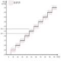
도 3은 본 발명의 일 실시예에 따른 디밍 제어 동작을 나타내는 그래프이다.
도 4는 본 발명의 일 실시예에 따른 IoT 스마트 LED 가로등 무선 제어 장치의 이용 방법의 흐름도이다.1 is a conceptual diagram of an IoT smart LED streetlight radio control device according to the present invention.
2 is a block diagram of an IoT smart LED streetlight radio control apparatus according to an embodiment of the present invention.
3 is a graph illustrating a dimming control operation according to an embodiment of the present invention.
4 is a flow diagram of a method of using an IoT smart LED streetlight radio control device in accordance with an embodiment of the present invention.
본 발명은 다양한 변경을 가할 수 있고 여러 가지 실시예를 가질 수 있는 바, 특정 실시 예들을 도면에 예시하고 발명을 실시하기 위한 구체적인 내용에 상세하게 설명하고자 한다. 그러나, 이는 본 발명을 특정한 실시 형태에 대해 한정하려는 것이 아니며, 본 발명의 사상 및 기술 범위에 포함되는 모든 변경, 균등물 내지 대체물을 포함하는 것으로 이해되어야 한다. 각 도면을 설명하면서 유사한 참조부호를 유사한 구성요소에 대해 사용하였다.While the invention is susceptible to various modifications and alternative forms, specific embodiments thereof are shown by way of example in the drawings and will herein be described in detail to the concrete inventive concept. It should be understood, however, that the invention is not intended to be limited to the particular embodiments, but includes all modifications, equivalents, and alternatives falling within the spirit and scope of the invention. Like reference numerals are used for like elements in describing each drawing.
제1, 제2, A, B 등의 용어는 다양한 구성요소들을 설명하는데 사용될 수 있지만, 상기 구성요소들은 상기 용어들에 의해 한정되어서는 안 된다. 상기 용어들은 하나의 구성요소를 다른 구성요소로부터 구별하는 목적으로만 사용된다. 예를 들어, 본 발명의 권리 범위를 벗어나지 않으면서 제1 구성요소는 제2 구성요소로 명명될 수 있고, 유사하게 제2 구성요소도 제1 구성요소로 명명될 수 있다. 및/또는 이라는 용어는 복수의 관련된 기재된 항목들의 조합 또는 복수의 관련된 기재된 항목들 중의 어느 항목을 포함한다.The terms first, second, A, B, etc. may be used to describe various elements, but the elements should not be limited by the terms. The terms are used only for the purpose of distinguishing one component from another. For example, without departing from the scope of the present invention, the first component may be referred to as a second component, and similarly, the second component may also be referred to as a first component. And / or < / RTI > includes any combination of a plurality of related listed items or any of a plurality of related listed items.
어떤 구성요소가 다른 구성요소에 "연결되어" 있다거나 "접속되어" 있다고 언급된 때에는, 그 다른 구성요소에 직접적으로 연결되어 있거나 또는 접속되어 있을 수도 있지만, 중간에 다른 구성요소가 존재할 수도 있다고 이해되어야 할 것이다. 반면에, 어떤 구성요소가 다른 구성요소에 "직접 연결되어" 있다거나 "직접 접속되어" 있다고 언급된 때에는, 중간에 다른 구성요소가 존재하지 않는 것으로 이해되어야 할 것이다.It is to be understood that when an element is referred to as being "connected" or "connected" to another element, it may be directly connected or connected to the other element, . On the other hand, when an element is referred to as being "directly connected" or "directly connected" to another element, it should be understood that there are no other elements in between.
본 출원에서 사용한 용어는 단지 특정한 실시예를 설명하기 위해 사용된 것으로, 본 발명을 한정하려는 의도가 아니다. 단수의 표현은 문맥상 명백하게 다르게 뜻하지 않는 한, 복수의 표현을 포함한다. 본 출원에서, "포함하다" 또는 "가지다" 등의 용어는 명세서상에 기재된 특징, 숫자, 단계, 동작, 구성요소, 부품 또는 이들을 조합한 것이 존재함을 지정하려는 것이지, 하나 또는 그 이상의 다른 특징들이나 숫자, 단계, 동작, 구성요소, 부품 또는 이들을 조합한 것들의 존재 또는 부가 가능성을 미리 배제하지 않는 것으로 이해되어야 한다.The terminology used in this application is used only to describe a specific embodiment and is not intended to limit the invention. The singular expressions include plural expressions unless the context clearly dictates otherwise. In the present application, the terms "comprises" or "having" and the like are used to specify that there is a feature, a number, a step, an operation, an element, a component or a combination thereof described in the specification, But do not preclude the presence or addition of one or more other features, integers, steps, operations, elements, components, or combinations thereof.
다르게 정의되지 않는 한, 기술적이거나 과학적인 용어를 포함해서 여기서 사용되는 모든 용어들은 본 발명이 속하는 기술 분야에서 통상의 지식을 가진 자에 의해 일반적으로 이해되는 것과 동일한 의미를 가지고 있다. 일반적으로 사용되는 사전에 정의되어 있는 것과 같은 용어들은 관련 기술의 문맥 상 가지는 의미와 일치하는 의미를 가지는 것으로 해석되어야 하며, 본 출원에서 명백하게 정의하지 않는 한, 이상적이거나 과도하게 형식적인 의미로 해석되지 않는다.Unless defined otherwise, all terms used herein, including technical or scientific terms, have the same meaning as commonly understood by one of ordinary skill in the art to which this invention belongs. Terms such as those defined in commonly used dictionaries are to be interpreted as having a meaning consistent with the contextual meaning of the related art and are to be interpreted as either ideal or overly formal in the sense of the present application Do not.
이하, 본 발명에 따른 바람직한 실시예를 첨부된 도면을 참조하여 상세하게 설명한다.Hereinafter, preferred embodiments according to the present invention will be described in detail with reference to the accompanying drawings.
도 1은 본 발명에 따른 IoT 스마트 LED 가로등 무선 제어 장치의 개념도이다.1 is a conceptual diagram of an IoT smart LED streetlight radio control device according to the present invention.
도 1에서는 본 발명에 따른 IoT 스마트 LED 가로등 무선 제어 장치(100)들의 연결 관계 및 서버(server)와의 연결망을 나타내고 있다.FIG. 1 shows a connection relationship of the IoT smart LED streetlight
IoT 스마트 LED 가로등 무선 제어 장치(100)는 WLAN과 같은 무선 통신을 이용하여 주변의 IoT 스마트 LED 가로등 무선 제어 장치(100) 간 통신이 가능하도록 구성되며, 무선 게이트웨이(wireless gateway)를 이용하여 원격지의 서버와 통신하도록 구성될 수 있다.The IoT smart LED streetlight
IoT 스마트 LED 가로등 무선 제어 장치(100)는 여러 센싱 정보를 수집하여 원격지의 서버로 정보를 제공하고, 원격지의 서버는 이러한 센싱 정보를 수신하여 필요한 제어 명령을 생성하고 이를 해당 IoT 스마트 LED 가로등 무선 제어 장치(100)로 제공하도록 구성될 수 있다. IoT 스마트 LED 가로등 무선 제어 장치(100)는 제어 명령에 따라 동작하도록 구성될 수 있다.The IoT smart LED streetlight
아울러, IoT 스마트 LED 가로등 무선 제어 장치(100)는 센싱 정보를 이용하여 직접 동작을 자동 제어하도록 구성될 수 있다.In addition, the IoT smart LED streetlight
도 2는 본 발명의 일 실시예에 따른 IoT 스마트 LED 가로등 무선 제어 장치의 블록 구성도이고, 도 3은 본 발명의 일 실시예에 따른 디밍 제어 동작을 나타내는 그래프이다.FIG. 2 is a block diagram of an IoT smart LED streetlight radio control apparatus according to an embodiment of the present invention, and FIG. 3 is a graph illustrating a dimming control operation according to an embodiment of the present invention.
도 2를 참조하면, 본 발명의 일 실시예에 따른 IoT 스마트 LED 가로등 무선 제어 장치(100)는 LED 스마트 콘트롤 모듈(110), 조도 센서(120), 디밍 제어 모듈(130), 고장 감지 모듈(140), 무선 통신 모듈(150), 제어 모듈(160)을 포함하도록 구성될 수 있다.2, the IoT smart LED streetlight
이하, 세부적인 구성에 대하여 설명한다.Hereinafter, the detailed configuration will be described.
LED 스마트 콘트롤 모듈(110)은 발광 다이오드로서 상용 전력 또는 태양광 전력을 공급받아 발광하도록 구성될 수 있다.The LED
조도 센서(120)는 주변의 조도를 감지하도록 구성될 수 있다. 조도 센서(120)를 이용하여 주간과 야간을 구별할 수 있으며, 날이 흐린 날씨도 구별할 수 있다.The
디밍 제어 모듈(130)은 조도 센서(120)를 디밍 제어하도록 구성될 수 있다. 디밍 제어 모듈(130)은 조도 센서(120)에 의해 감지된 현재의 조도에 따라 LED 스마트 콘트롤 모듈(110)의 동작을 디밍 제어할 수 있다.The
도 2에서는 이러한 디밍 제어를 나타내는 그래프를 도시하고 있다.Fig. 2 shows a graph showing such dimming control.
고장 감지 모듈(140)은 LED 스마트 콘트롤 모듈(110) 및 디밍 제어 모듈(130)의 고장을 감지하도록 구성될 수 있다.The
도 2를 참조하면, 고장 감지 모듈(140)은 먼저 LED 스마트 콘트롤 모듈(110)의 전류를 검출하도록 구성될 수 있다. 고장 감지 모듈(140)은 검출된 전류를 전압값으로 환산하고, 그 전압값이 소정의 범위 내에 속하는지 여부를 판단하도록 구성될 수 있다. 도 2의 그래프에서는 각각의 디밍 제어값에 대해 정상 동작 영역으로 표시되어 있다. 환산된 전압값이 해당하는 정상 동작 영역 내에 있는 경우에는 정상적인 동작으로 파악하고, 그렇지 않은 경우에는 디밍 제어 내지는 LED 발광 동작이 오류인 것으로 판단할 수 있다.Referring to FIG. 2, the
오류인 것으로 판단된 경우, 고장 감지 모듈(140)은 해당 오류 신호를 제어 모듈(160)로 송신하도록 구성될 수 있다. 제어 모듈(160)은 무선 통신 모듈(150)을 통해 서버(20)로 송신하도록 구성될 수 있다.If it is determined to be an error, the
오류 판단 동작은 좀 더 구체적으로는 다음과 같다.More specifically, the error determination operation is as follows.
고장 감지 모듈(140)은 2차적으로 전류 검출값 즉, 환산된 전압값이 0이 아니어야 함에도 불구하고 0으로 환산되는 경우 즉, 전류가 0이고 디밍 제어가 50% 이상인 경우에는 전원 케이블이 고장인 것으로 판단할 수 있다. 그리고 전원 케이블 고장을 제어 모듈(160)로 즉시 통지하도록 구성될 수 있다.If the current detection value is converted to 0 in spite of the fact that the converted voltage value should not be 0 but the current is 0 and the dimming control is 50% . ≪ / RTI > And notify the
그러나, 전류가 0이 아닌 경우에는 LED 스마트 콘트롤 모듈(110) 자체의 고장인 것으로 잠정적으로 판단할 수 있다. 그리고 LED 스마트 콘트롤 모듈(110)의 고장을 제어 모듈(160)로 즉시 통지하도록 구성될 수 있다.However, if the current is not 0, it can be judged provisionally that it is a failure of the LED
무선 통신 모듈(150)은 주변의 다른 IoT 스마트 LED 가로등 무선 제어 장치(100)와 근거리 통신을 수행하며, 무선 게이트웨이(wireless gateway)(10)를 통해 서버(20)와 통신하도록 구성될 수 있다.The
한편, 무선 통신 모듈(150)은 제어 모듈(160)의 고장 감지 신호를 서버(20)로 송신하며, 서버(20)로부터 제어 명령을 수신하여 제어 모듈(160)로 전달하도록 구성될 수 있다.The
제어 모듈(160)은 IoT 스마트 LED 가로등 무선 제어 장치(100)의 전반적인 동작을 자동 제어하며, 서버(20)의 제어 명령에 따라 제어하도록 구성될 수 있다. 제어 모듈(160)은 디밍 제어 모듈(120)을 제어하도록 구성될 수 있다.The
제어 모듈(160)은 고장 감지 모듈(140)에 의해 고장이 감지되면, 해당하는 고장 감지 신호를 생성하여 무선 통신 모듈(150)을 통해 서버(20)로 송신하도록 구성될 수 있다.When the failure is detected by the
한편, 제어 모듈(160)은 LED 스마트 콘트롤 모듈(110)의 고장 또는 전원 케이블의 고장 등이 감지되어 발광을 할 수 없는 경우, 해당하는 고장 감지 신호를 생성하여 무선 통신 모듈(150)을 통해 주변의 다른 IoT 스마트 LED 가로등 무선 제어 장치(100)로 송신하도록 구성될 수 있다. 이때, 주변의 다른 IoT 스마트 LED 가로등 무선 제어 장치(100)의 제어 모듈(160)은 LED 스마트 콘트롤 모듈(110)의 밝기를 더 높여 고장난 IoT 스마트 LED 가로등 무선 제어 장치(100)에 의한 조도 감소를 자동으로 보완하도록 구성될 수 있다. 물론, 서버(20)에 의해 주변의 다른 IoT 스마트 LED 가로등 무선 제어 장치(100)로 조도 보완 제어 명령을 송신할 수도 있다. 아울러 발광을 할 수 없는 경우는 물론 제어하고자 하는 조도에 미치지 못하는 경우에도 주변의 다른 IoT 스마트 LED 가로등 무선 제어 장치(100)가 조도를 보완하도록 제어할 수 있다.Meanwhile, when the LED
다른 한편, 제어 모듈(160)은 서버(20)로부터 각종 정보를 수신할 수 있으며, 이를 이용하여 LED 스마트 콘트롤 모듈(110)의 발광 색상을 제어할 수도 있다. 예를 들어, 일기 예보 정보라든가 주변의 차량 막힘 정보, 대기질 정보 등을 수신하여 이에 따른 각각의 색상 제어를 하도록 구성될 수 있다.On the other hand, the
도 4는 본 발명의 일 실시예에 따른 IoT 스마트 LED 가로등 장치의 이용 방법의 흐름도이다.4 is a flow diagram of a method of using an IoT smart LED streetlight device in accordance with an embodiment of the present invention.
도 4를 참조하면, 먼저 제어 모듈(160)이 무선 통신 모듈(150)을 통해 서버(20)로부터 제어 명령을 수신하여 LED 스마트 콘트롤 모듈(110)을 자동 제어한다(S101).4, the
다음으로, 제어 모듈(160)의 제어에 의해 LED(light emitting diode) 발광 모듈(110)이 발광한다(S102).Next, the LED (light emitting diode) light emitting
여기서, 제어 모듈(160)의 제어에 따라 조도 센서(120)가 주변의 조도를 감지하고 디밍 제어 모듈(130)이 조도 센서(120)에서 감지된 조도에 따라 LED 스마트 콘트롤 모듈(110)을 디밍 제어하도록 구성될 수 있다.The dimming
다음으로, 고장 감지 모듈(140)이 LED 스마트 콘트롤 모듈(110)의 고장을 감지한다(S103).Next, the
다음으로, 고장 감지 모듈(140)에 의해 고장이 감지되는 경우, 제어 모듈(160)이 고장 감지 신호를 생성한다(S104).Next, when a failure is detected by the
다음으로, 무선 통신 모듈(150)이 생성된 고장 감지 신호를 서버(20)로 송신한다(S105).Next, the
이상 실시예를 참조하여 설명하였지만, 해당 기술 분야의 숙련된 당업자는 하기의 특허청구범위에 기재된 본 발명의 사상 및 영역으로부터 벗어나지 않는 범위 내에서 본 발명을 다양하게 수정 및 변경시킬 수 있음을 이해할 수 있을 것이다.It will be apparent to those skilled in the art that various modifications and variations can be made in the present invention without departing from the spirit or scope of the invention as defined in the following claims. There will be.
110: LED 스마트 콘트롤 모듈
120: 조도 센서
130: 디밍 제어 모듈
140: 고장 감지 모듈
150: 무선 통신 모듈
160: 제어 모듈110: LED Smart Control Module
120: Light intensity sensor
130: Dimming control module
140: Fault detection module
150: Wireless communication module
160: Control module
Claims (6)
Translated fromKorean주변의 다른 IoT 스마트 LED 가로등 장치와 근거리 통신을 수행하며, 무선 게이트웨이(wireless gateway)를 통해 서버(server)와 통신하는 무선 통신 모듈;
상기 무선 통신 모듈을 통해 상기 서버로부터 제어 명령을 수신하여 제어하고, 고장 감지 신호를 상기 무선 통신 모듈을 통해 상기 서버로 송신하도록 제어하는 제어 모듈;
주변의 조도를 감지하는 조도 센서;
상기 조도 센서에서 감지된 조도에 따라 상기 LED 스마트 콘트롤 모듈을 디밍 제어하는 디밍(dimming) 제어 모듈;
상기 LED 스마트 콘트롤 모듈의 고장을 감지하는 고장 감지 모듈을 포함하고,
상기 고장 감지 모듈은,
상기 LED 스마트 콘트롤 모듈의 전류값을 검출하고, 검출된 전류값을 전류값에 상응하는 전압값으로 환산하고, 환산된 전압값이 상기 디밍 제어 모듈의 디밍 제어에 상응하는 값에 대해 미리 정해진 정상 동작 영역 내에 있는지 판단하고, 판단 결과 상기 환산된 전압값이 해당 정상 동작 영역 내에 있는 경우에는 디밍 제어 또는 발광이 정상인 것으로 판단하고, 판단 결과 상기 환산된 전압값이 해당 정상 동작 영역 내에 있지 않은 경우에는 디밍 제어 또는 발광이 정상이 아닌 것으로 판단하며,
상기 제어 모듈은,
상기 고장 감지 모듈에서 고장이 감지되면 상기 고장 감지 신호를 생성하여 상기 무선 통신 모듈을 통해 상기 서버로 송신하도록 제어하며,
상기 고장 감지 모듈은,
상기 LED 스마트 콘트롤 모듈을 제어하기 위한 제어 명령에 상응하는 전류값이 0이 아니어야 하는데 상기 환산된 전압값이 0이고 상기 디밍 제어가 50% 이상이면 전원 케이블이 고장인 것으로 판단하고, 상기 전류값이 0이 아닌 경우에는 상기 LED 스마트 콘트롤 모듈 자체의 고장인 것으로 판단하도록 구성되며,
상기 제어 모듈은,
상기 전원 케이블의 고장 또는 상기 LED 스마트 콘트롤 모듈의 고장으로 판단되는 경우, 상기 주변의 다른 IoT 스마트 LED 가로등 무선 제어 장치가 해당 LED 스마트 콘트롤 모듈의 밝기를 더 높여 상기 전원 케이블 또는 상기 LED 스마트 콘트롤 모듈의 고장에 따른 조도의 감소를 자동으로 보완할 수 있도록 하는 조도 보완 제어 명령을 생성하여 상기 무선 통신 모듈을 통해 상기 주변의 다른 IoT 스마트 LED 가로등 무선 제어 장치로 송신하도록 구성되며,
상기 제어 모듈은,
상기 서버로부터 일기 예보 정보, 주변 차량 막힘 정보 및 대기질 정보를 수신하고, 수신된 일기 예보 정보, 주변 차량 막힘 정보 및 대기질 정보에 대응하여 상기 LED 스마트 콘트롤 모듈의 발광 색상을 제어하도록 구성되는 것을 특징으로 하는 IoT 스마트 LED 가로등 무선 제어 장치.LED smart control module that emits light by receiving commercial power or solar power;
A wireless communication module for performing close-range communication with other IoT smart LED streetlight devices in the vicinity and communicating with a server through a wireless gateway;
A control module for receiving and controlling a control command from the server through the wireless communication module, and for transmitting a failure detection signal to the server through the wireless communication module;
An illuminance sensor for sensing a surrounding illuminance;
A dimming control module for controlling dimming of the LED smart control module according to the illuminance sensed by the illuminance sensor;
And a failure detection module for detecting a failure of the LED smart control module,
The fault detection module includes:
A current value of the LED smart control module is detected, a detected current value is converted into a voltage value corresponding to the current value, and the converted voltage value is compared with a predetermined normal operation If the converted voltage value is within the normal operation region, it is determined that dimming control or light emission is normal. If the calculated voltage value is not within the normal operation region, It is determined that the control or the light emission is not normal,
The control module includes:
When the failure is detected in the failure detection module, the failure detection signal is generated and transmitted to the server through the wireless communication module,
The fault detection module includes:
It is determined that the current value corresponding to the control command for controlling the LED smart control module is not 0 and the power cable is broken if the converted voltage value is 0 and the dimming control is 50% Is not 0, it is determined that the LED is the failure of the smart control module itself,
The control module includes:
If the failure of the power cable or the failure of the LED smart control module is determined, the other IoT smart LED streetlight wireless control device in the vicinity further increases the brightness of the corresponding LED smart control module so that the power cable or the LED smart control module And generating an illumination compensation command to automatically compensate for a decrease in illuminance caused by a failure, and to transmit the illuminance supplement control command to the other IoT smart LED streetlight wireless control device through the wireless communication module,
The control module includes:
Receiving the weather forecast information, the surrounding vehicle clogging information, and the air quality information from the server, and controlling the emission color of the LED smart control module according to the received weather forecast information, surrounding vehicle clogging information, and air quality information Featuring IoT Smart LED Streetlight Radio Control Device.
Priority Applications (1)
| Application Number | Priority Date | Filing Date | Title |
|---|---|---|---|
| KR1020180026267AKR101923620B1 (en) | 2018-03-06 | 2018-03-06 | APPARATUS OF WIRELESS CONTROl FOR INTERNET OF THINGS SMART LIGHT EMITTING DIODE STREETLAMP AND METHOD OF USING THE SAME |
Applications Claiming Priority (1)
| Application Number | Priority Date | Filing Date | Title |
|---|---|---|---|
| KR1020180026267AKR101923620B1 (en) | 2018-03-06 | 2018-03-06 | APPARATUS OF WIRELESS CONTROl FOR INTERNET OF THINGS SMART LIGHT EMITTING DIODE STREETLAMP AND METHOD OF USING THE SAME |
Publications (1)
| Publication Number | Publication Date |
|---|---|
| KR101923620B1true KR101923620B1 (en) | 2018-11-29 |
Family
ID=64566995
Family Applications (1)
| Application Number | Title | Priority Date | Filing Date |
|---|---|---|---|
| KR1020180026267AActiveKR101923620B1 (en) | 2018-03-06 | 2018-03-06 | APPARATUS OF WIRELESS CONTROl FOR INTERNET OF THINGS SMART LIGHT EMITTING DIODE STREETLAMP AND METHOD OF USING THE SAME |
Country Status (1)
| Country | Link |
|---|---|
| KR (1) | KR101923620B1 (en) |
Cited By (1)
| Publication number | Priority date | Publication date | Assignee | Title |
|---|---|---|---|---|
| CN113747638A (en)* | 2021-08-31 | 2021-12-03 | 深圳市凯铭电气照明有限公司 | Internet of things communication data processing method of intelligent lamp pole |
- 2018
- 2018-03-06KRKR1020180026267Apatent/KR101923620B1/enactiveActive
Cited By (2)
| Publication number | Priority date | Publication date | Assignee | Title |
|---|---|---|---|---|
| CN113747638A (en)* | 2021-08-31 | 2021-12-03 | 深圳市凯铭电气照明有限公司 | Internet of things communication data processing method of intelligent lamp pole |
| CN113747638B (en)* | 2021-08-31 | 2024-04-26 | 深圳市凯铭智慧建设科技有限公司 | Internet of things communication data processing method for intelligent lamp post |
Similar Documents
| Publication | Publication Date | Title |
|---|---|---|
| US9385806B2 (en) | Visible light communication device | |
| US20090002982A1 (en) | Outdoor lighting system with controlled luminance | |
| EP2733416A1 (en) | Led light and led lighting system | |
| US20100204847A1 (en) | Wireless infrastructure mesh network system using a lighting node | |
| US9532438B2 (en) | System and method for wirelessly controlling LED lighting | |
| KR101183359B1 (en) | Dimming control system for street lighting | |
| KR20190063554A (en) | DIMMING CONTROL SYSTEM OF LED STREETLIGHT AND SECURITY LIGHT BASED ON IoT | |
| JP6508464B2 (en) | LIGHTING SYSTEM, CONTROL METHOD, AND CONTROL DEVICE | |
| KR20110003192A (en) | Street light system | |
| EP2739122A1 (en) | Led lighting device and led lighting network system | |
| KR100904792B1 (en) | LED Lighting and LED Emitting Device Management System | |
| US11064591B2 (en) | Flooding localization and signalling via intelligent lighting | |
| MX2015005583A (en) | ANTENNA SENSOR, LAMP THAT INCLUDES THE SAME AND CONDITIONING METHOD OF THE SAME. | |
| US20170118820A1 (en) | Method for illuminating a light box | |
| KR101663542B1 (en) | Intelligent Control System of StreetLamp | |
| KR20190115482A (en) | Wireless control apparatus of internet of things smart light emitting diode streetlamp apparatus equipped with situation detection fuction method thereof | |
| KR101923620B1 (en) | APPARATUS OF WIRELESS CONTROl FOR INTERNET OF THINGS SMART LIGHT EMITTING DIODE STREETLAMP AND METHOD OF USING THE SAME | |
| JP2013065452A (en) | Lighting system | |
| KR20130030925A (en) | Led lighting device group control dimming system with visible light wireless communication | |
| US9763304B2 (en) | Visible light communication apparatus and method for manufacturing visible light communication apparatus | |
| US20150028757A1 (en) | Single wire lighting driver control | |
| JP2017091843A (en) | LIGHTING SYSTEM AND LIGHTING DEVICE USED FOR THE SAME | |
| CN116390295A (en) | Dimming control circuit, dimming control method and lighting system | |
| KR102279076B1 (en) | Smart Operating Device in LED Light Fixture | |
| KR101698346B1 (en) | An ac wall switch performing led lights controls without supplemental power wires |
Legal Events
| Date | Code | Title | Description |
|---|---|---|---|
| PA0109 | Patent application | St.27 status event code:A-0-1-A10-A12-nap-PA0109 | |
| PA0201 | Request for examination | St.27 status event code:A-1-2-D10-D11-exm-PA0201 | |
| PA0302 | Request for accelerated examination | St.27 status event code:A-1-2-D10-D17-exm-PA0302 St.27 status event code:A-1-2-D10-D16-exm-PA0302 | |
| D13-X000 | Search requested | St.27 status event code:A-1-2-D10-D13-srh-X000 | |
| D14-X000 | Search report completed | St.27 status event code:A-1-2-D10-D14-srh-X000 | |
| PE0902 | Notice of grounds for rejection | St.27 status event code:A-1-2-D10-D21-exm-PE0902 | |
| T11-X000 | Administrative time limit extension requested | St.27 status event code:U-3-3-T10-T11-oth-X000 | |
| E13-X000 | Pre-grant limitation requested | St.27 status event code:A-2-3-E10-E13-lim-X000 | |
| P11-X000 | Amendment of application requested | St.27 status event code:A-2-2-P10-P11-nap-X000 | |
| P13-X000 | Application amended | St.27 status event code:A-2-2-P10-P13-nap-X000 | |
| E90F | Notification of reason for final refusal | ||
| PE0902 | Notice of grounds for rejection | St.27 status event code:A-1-2-D10-D21-exm-PE0902 | |
| P11-X000 | Amendment of application requested | St.27 status event code:A-2-2-P10-P11-nap-X000 | |
| P13-X000 | Application amended | St.27 status event code:A-2-2-P10-P13-nap-X000 | |
| E701 | Decision to grant or registration of patent right | ||
| PE0701 | Decision of registration | St.27 status event code:A-1-2-D10-D22-exm-PE0701 | |
| GRNT | Written decision to grant | ||
| PR0701 | Registration of establishment | St.27 status event code:A-2-4-F10-F11-exm-PR0701 | |
| PR1002 | Payment of registration fee | St.27 status event code:A-2-2-U10-U11-oth-PR1002 Fee payment year number:1 | |
| PG1601 | Publication of registration | St.27 status event code:A-4-4-Q10-Q13-nap-PG1601 | |
| P22-X000 | Classification modified | St.27 status event code:A-4-4-P10-P22-nap-X000 | |
| P22-X000 | Classification modified | St.27 status event code:A-4-4-P10-P22-nap-X000 | |
| R18-X000 | Changes to party contact information recorded | St.27 status event code:A-5-5-R10-R18-oth-X000 | |
| PN2301 | Change of applicant | St.27 status event code:A-5-5-R10-R11-asn-PN2301 | |
| PN2301 | Change of applicant | St.27 status event code:A-5-5-R10-R14-asn-PN2301 | |
| P14-X000 | Amendment of ip right document requested | St.27 status event code:A-5-5-P10-P14-nap-X000 | |
| P16-X000 | Ip right document amended | St.27 status event code:A-5-5-P10-P16-nap-X000 | |
| Q16-X000 | A copy of ip right certificate issued | St.27 status event code:A-4-4-Q10-Q16-nap-X000 | |
| PR1001 | Payment of annual fee | St.27 status event code:A-4-4-U10-U11-oth-PR1001 Fee payment year number:4 | |
| P22-X000 | Classification modified | St.27 status event code:A-4-4-P10-P22-nap-X000 | |
| R18-X000 | Changes to party contact information recorded | St.27 status event code:A-5-5-R10-R18-oth-X000 | |
| PR1001 | Payment of annual fee | St.27 status event code:A-4-4-U10-U11-oth-PR1001 Fee payment year number:5 | |
| PR1001 | Payment of annual fee | St.27 status event code:A-4-4-U10-U11-oth-PR1001 Fee payment year number:6 | |
| PR1001 | Payment of annual fee | St.27 status event code:A-4-4-U10-U11-oth-PR1001 Fee payment year number:7 | |
| PN2301 | Change of applicant | St.27 status event code:A-5-5-R10-R11-asn-PN2301 | |
| PN2301 | Change of applicant | St.27 status event code:A-5-5-R10-R14-asn-PN2301 | |
| P14-X000 | Amendment of ip right document requested | St.27 status event code:A-5-5-P10-P14-nap-X000 | |
| P16-X000 | Ip right document amended | St.27 status event code:A-5-5-P10-P16-nap-X000 | |
| Q16-X000 | A copy of ip right certificate issued | St.27 status event code:A-4-4-Q10-Q16-nap-X000 | |
| P22-X000 | Classification modified | St.27 status event code:A-4-4-P10-P22-nap-X000 |