KR101920705B1 - Spray Valve Having Structure for Controlling Quantity of Water, and Deaerator Having the Same - Google Patents
Spray Valve Having Structure for Controlling Quantity of Water, and Deaerator Having the SameDownload PDFInfo
- Publication number
- KR101920705B1 KR101920705B1KR1020160134069AKR20160134069AKR101920705B1KR 101920705 B1KR101920705 B1KR 101920705B1KR 1020160134069 AKR1020160134069 AKR 1020160134069AKR 20160134069 AKR20160134069 AKR 20160134069AKR 101920705 B1KR101920705 B1KR 101920705B1
- Authority
- KR
- South Korea
- Prior art keywords
- spray valve
- spray
- nozzle piston
- valve cylinder
- inlet pipe
- Prior art date
- Legal status (The legal status is an assumption and is not a legal conclusion. Google has not performed a legal analysis and makes no representation as to the accuracy of the status listed.)
- Active
Links
Images


Classifications
- B—PERFORMING OPERATIONS; TRANSPORTING
- B05—SPRAYING OR ATOMISING IN GENERAL; APPLYING FLUENT MATERIALS TO SURFACES, IN GENERAL
- B05B—SPRAYING APPARATUS; ATOMISING APPARATUS; NOZZLES
- B05B1/00—Nozzles, spray heads or other outlets, with or without auxiliary devices such as valves, heating means
- B05B1/30—Nozzles, spray heads or other outlets, with or without auxiliary devices such as valves, heating means designed to control volume of flow, e.g. with adjustable passages
- B05B1/3006—Nozzles, spray heads or other outlets, with or without auxiliary devices such as valves, heating means designed to control volume of flow, e.g. with adjustable passages the controlling element being actuated by the pressure of the fluid to be sprayed
- B—PERFORMING OPERATIONS; TRANSPORTING
- B01—PHYSICAL OR CHEMICAL PROCESSES OR APPARATUS IN GENERAL
- B01D—SEPARATION
- B01D19/00—Degasification of liquids
- B01D19/0063—Regulation, control including valves and floats
- B—PERFORMING OPERATIONS; TRANSPORTING
- B05—SPRAYING OR ATOMISING IN GENERAL; APPLYING FLUENT MATERIALS TO SURFACES, IN GENERAL
- B05B—SPRAYING APPARATUS; ATOMISING APPARATUS; NOZZLES
- B05B1/00—Nozzles, spray heads or other outlets, with or without auxiliary devices such as valves, heating means
- B05B1/30—Nozzles, spray heads or other outlets, with or without auxiliary devices such as valves, heating means designed to control volume of flow, e.g. with adjustable passages
- B05B1/3013—Lift valves
- F—MECHANICAL ENGINEERING; LIGHTING; HEATING; WEAPONS; BLASTING
- F16—ENGINEERING ELEMENTS AND UNITS; GENERAL MEASURES FOR PRODUCING AND MAINTAINING EFFECTIVE FUNCTIONING OF MACHINES OR INSTALLATIONS; THERMAL INSULATION IN GENERAL
- F16K—VALVES; TAPS; COCKS; ACTUATING-FLOATS; DEVICES FOR VENTING OR AERATING
- F16K3/00—Gate valves or sliding valves, i.e. cut-off apparatus with closing members having a sliding movement along the seat for opening and closing
- F16K3/22—Gate valves or sliding valves, i.e. cut-off apparatus with closing members having a sliding movement along the seat for opening and closing with sealing faces shaped as surfaces of solids of revolution
- F16K3/24—Gate valves or sliding valves, i.e. cut-off apparatus with closing members having a sliding movement along the seat for opening and closing with sealing faces shaped as surfaces of solids of revolution with cylindrical valve members
- F—MECHANICAL ENGINEERING; LIGHTING; HEATING; WEAPONS; BLASTING
- F16—ENGINEERING ELEMENTS AND UNITS; GENERAL MEASURES FOR PRODUCING AND MAINTAINING EFFECTIVE FUNCTIONING OF MACHINES OR INSTALLATIONS; THERMAL INSULATION IN GENERAL
- F16K—VALVES; TAPS; COCKS; ACTUATING-FLOATS; DEVICES FOR VENTING OR AERATING
- F16K3/00—Gate valves or sliding valves, i.e. cut-off apparatus with closing members having a sliding movement along the seat for opening and closing
- F16K3/30—Details
- F16K3/314—Forms or constructions of slides; Attachment of the slide to the spindle
Landscapes
- Engineering & Computer Science (AREA)
- General Engineering & Computer Science (AREA)
- Mechanical Engineering (AREA)
- Chemical & Material Sciences (AREA)
- Chemical Kinetics & Catalysis (AREA)
- Nozzles (AREA)
Abstract
Translated fromKoreanDescription
Translated fromKorean본 발명은 탈기기에 장착되는 스프레이 밸브 및 이를 포함하는 탈기기에 관한 것으로서, 보다 상세하게는 스프레이 타입 탈기기에 적합한 스프레이 밸브 및 이를 포함하는 탈기기에 관한 것이다.BACKGROUND OF THE INVENTION 1. Field of the Invention The present invention relates to a spray valve mounted on a deaerator, and a deaerator including the same, and more particularly, to a spray valve suitable for spray type deaerating device and deaerator including the same.
스프레이 밸브는 탈기기의 핵심부품 중에 한 구성요소로서, 용존산소 및 기타 비응축가스를 함유한 상태로 탈기기 내로 유입되는 용수를 분사하여 원통형의 얇은 수막을 형성하는 밸브이다.The spray valve is one of the key components of the deaerator and is a valve that forms a cylindrical thin membrane by spraying the water that flows into the deaerator with dissolved oxygen and other non-condensable gases.
탈기기에 형성된 다른 입구로 유입된 증기는 스프레이 밸브를 통해 원통형 얇은 막의 형태로 분사되는 용수를 통과하면서 용수의 온도를 상승시켜 기체를 탈기시킨다.The vapor introduced into the other inlet formed in the deaerator passes through the water sprayed in the form of a cylindrical thin film through the spray valve while raising the temperature of the water to degas the gas.
탈기기의 탈기기능은 스프레이 밸브의 수량에 따라 결정되며, 작동원리는 용수의 압력을 최소 0.13Kg/cm2 이상으로 유지시켜 스프레이 밸브의 스프링을 압축함으로써 밸브가 개방되어 용수를 분사한다.The degassing function of the deaerator is determined by the number of spray valves. The operating principle is to keep the water pressure at least 0.13 kg / cm2 or more and compress the spring of the spray valve to open the valve and spray the water.
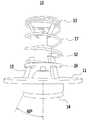
도 1에는 종래 기술에 따른 스프레이 밸브를 나타내는 사시도가 도시되어 있다.1 is a perspective view showing a conventional spray valve.
이와 같이 구성된 종래의 스프레이 밸브(10)는 배관에 체결되는 플랜지(11)와, 플랜지(11)의 중공에 삽입된 축(12)과, 상기 축(12)의 일단에 고정되어 용수가 유입되는 방향의 상류를 향해 개방된 고깔형상의 제 1 스프링 지지대(13)와, 용수의 분사방향을 안내하는 고깔형상의 개폐부(14)와, 상기 플랜지(11)의 중공 가장자리에 고정된 삼각대(15) 둘레에 고정되는 제 2 스프링 지지대(16)와, 제 1 스프링 지지대(13)와 제 2 스프링 지지대(16)에 양단이 각각 접해 위치하며 상기 축(12)의 이동에 따라 신축되는 압축코일 스프링(17)을 포함한다.The
이와 같이 구성된 종래의 스프레이 밸브(10)는 그 구성이 복잡하고, 용수 분사각도가 60도로서 분사각도가 좁아 탈기 효과가 떨어진다는 단점이 있다.The
또한, 종래 기술에 따른 스프레이 밸브(10)의 경우, 상방에서 하방으로 공급되는 급수배관의 하단부에 장착되어 하방으로 급수를 분사하고 있다. 이때, 스프레이 밸브(10)를 구성하고 있는 축(12), 제 1 스프링 지지대(13), 삼각대(15), 제 2 스프링 지지대(16) 및 압축코일 스프링(17)은 항상 급수에 노출되어 있어, 부식에 의해 손쉽게 손상될 수 있다.Further, in the case of the
또한, 종래 기술에 따른 스프레이 밸브(10)의 경우, 탈기기에 장착된 후, 압축코일 스프링(17)에 의해 고깔 형상의 개폐부(14)에 인가되는 압축력을 변경하기 위해서는, 스프레이 밸브(10)를 탈거해야 하는 불편함이 있었다.In order to change the compressive force applied to the conical opening /
또한, 종래 기술에 따른 스프레이 밸브(10)의 경우, 급수배관으로부터 인가되는 수압에 의해 고깔 형상의 개폐부(14)가 개방되어 분사 역할을 수행할 수 있으나, 급수배관으로부터 인가되는 수압에 따라 적절히 분사량을 조절할 수 없는 문제점을 가지고 있다.In the case of the
따라서, 상기 언급한 종래 기술에 따른 문제점을 해결할 수 있는 스프레이 밸브에 대한 기술이 필요한 실정이다.Therefore, there is a need for a technique for a spray valve that can solve the above-described problems in the related art.
본 발명의 목적은, 탈기기에 장착되는 스프레이 밸브의 수량을 감소시킬 수 있고, 급수유입관의 압력에 따라 분사량을 조절할 수 있는 구조를 포함하는 스프레이 밸브를 제공하는 것이다.An object of the present invention is to provide a spray valve including a structure capable of reducing the number of spray valves mounted on the deaerator and adjusting the injection quantity in accordance with the pressure of the water inlet pipe.
이러한 목적을 달성하기 위한 본 발명의 일 측면에 따른 스프레이 밸브는, 스프레이 타입 탈기기의 압력용기 내부로 인입되어 압력용기 내부 상방으로 소정 높이만큼 연장되어 설치된 급수유입관의 상단부에 장착되고, 급수유입관으로부터 제공되는 급수를 압력용기 내부로 분사하는 스프레이 밸브로서, 하부면이 개방된 원통형 실린더 구조이고, 하부면은 급수유입관의 상단부와 연통되고, 노즐 피스톤이 상하 방향 이동 가능하도록 내부 슬라이딩 공간이 마련되어 있으며, 외부면에 상하 방향 일정 간격으로 분사관통구가 다수 형성된 스프레이 밸브 실린더; 상기 스프레이 밸브 실린더의 내부면에 상하 방향 이동 가능하도록 장착되고, 급수유입관으로부터 유입되는 수압에 의해 상방으로 위치변경되는 노즐 피스톤; 및 상기 스프레이 밸브 실린더의 내부 상부면과 노즐 피스톤의 상부면 사이에 장착되어 노즐 피스톤을 하방으로 소정 크기의 가압력으로 가압하는 탄성부재;를 포함하는 구성일 수 있다.To achieve these and other advantages and in accordance with the purpose of the present invention, as embodied and broadly described herein, there is provided a spray valve according to one aspect of the present invention, which is installed in an upper portion of a water supply inlet pipe, A spray valve for spraying water supplied from a pipe into a pressure vessel, comprising: a cylindrical cylinder structure having a lower surface opened; a lower surface communicating with an upper end of the water inlet pipe; and an internal sliding space A spray valve cylinder having a plurality of spray through holes at regular intervals in an up and down direction on an outer surface thereof; A nozzle piston mounted on an inner surface of the spray valve cylinder so as to be vertically movable and being displaced upward by a water pressure introduced from the water supply inlet pipe; And an elastic member mounted between an inner upper surface of the spray valve cylinder and an upper surface of the nozzle piston to press the nozzle piston downward with a pressing force of a predetermined magnitude.
본 발명의 일 실시예에 있어서, 상기 스프레이 밸브 실린더의 외주면에는 압력용기와 결속되는 구조의 결속체결부가 장착될 수 있다.In an embodiment of the present invention, the outer circumferential surface of the spray valve cylinder may be provided with a fastening fastening portion having a structure to be coupled to the pressure vessel.
본 발명의 일 실시예에 있어서, 상기 노즐 피스톤(120)의 외주면에는 피스톤링(piston ring), 가스켓(gasket) 또는 오링(O-ring)이 장착될 수 있다.In an embodiment of the present invention, a piston ring, a gasket, or an O-ring may be mounted on the outer peripheral surface of the
본 발명의 일 실시예에 있어서, 상기 스프레이 밸브 실린더(110)의 내부면에는 노즐 피스톤(120)의 외주면에 형성된 돌기부(125)와 대응되는 형상의 만입부(115)가 상하 방향으로 형성되어 있고, 상기 노즐 피스톤(120)의 외주면에는 스프레이 밸브 실린더(110)의 내부면에 형성된 만입부(115)에 안착되는 돌기부(125)가 형성되어, 노즐 피스톤(120)의 상하 방향 움직임을 가이드 할 수 있다.A
본 발명의 일 실시예에 있어서, 상기 스프레이 밸브 실린더의 상부에는, 노즐 피스톤의 상하 방향 이동에 따라 공기가 출입할 수 있는 벤트홀이 형성될 수 있다.In an exemplary embodiment of the present invention, a vent hole may be formed in the upper portion of the spray valve cylinder to allow air to flow in and out of the nozzle piston as the nozzle piston moves up and down.
본 발명의 일 실시예에 있어서, 상기 스프레이 밸브 실린더의 외부면에 형성된 분사관통구는, 스프레이 밸브 실린더(110)의 외부면을 기준으로 측방으로 소정 각도만큼 기울어져 형성될 수 있다.In one embodiment of the present invention, the spray through-holes formed on the outer surface of the spray valve cylinder may be formed to be inclined sideways by a predetermined angle with respect to the outer surface of the
본 발명의 일 실시예에 있어서, 상기 노즐 피스톤은, 급수유입관으로부터 유입되는 수압을 받아 상방으로 위치변경되고, 스프레이 밸브 실린더의 내부면과 대응되는 구조의 평면구조를 가지는 판상형 구조의 하부판; 상기 하부판과 상부판 사이에 장착되어, 하부판과 상부판을 서로 소정 거리만큼 이격시켜 고정시키는 연결부; 및 상기 연결부의 상단에 장착되고, 탄성부재로부터 제공되는 탄성력을 연결부를 통해 하부판에 전달하는 상부판;을 포함하는 구성일 수 있다.In one embodiment of the present invention, the nozzle piston is a plate-shaped bottom plate having a planar structure of a structure corresponding to the inner surface of the spray valve cylinder, the bottom piston being displaced upward by receiving water pressure from the water supply inlet pipe; A connecting portion mounted between the bottom plate and the top plate for fixing the bottom plate and the top plate by a predetermined distance; And an upper plate mounted on an upper end of the connection portion and transmitting an elastic force provided from the elastic member to the lower plate through a connection portion.
경우에 따라서, 상기 연결부는, 상부판과 하부판 사이에 장착되는 판상형 구조, 원기둥 구조 또는 다각기둥 구조일 수 있다. 또한, 상기 연결부는, 스프레이 밸브 실린더의 내부 구조와 대응되는 구조의 실린더 구조일 수 있다.In some cases, the connecting portion may be a plate-like structure, a cylindrical structure, or a polygonal columnar structure mounted between the upper plate and the lower plate. In addition, the connection portion may be a cylinder structure having a structure corresponding to the internal structure of the spray valve cylinder.
본 발명의 일 실시예에 있어서, 상기 탄성부재는 이중 코일스프링일 수 있다.In an embodiment of the present invention, the elastic member may be a double coil spring.
본 발명의 일 실시예에 있어서, 상기 스프레이 밸브 실린더의 상부에는, 회전동작에 의해 상하 방향으로 위치 변경되는 상하조절 핸들이 장착되고, 상기 상하조절 핸들의 하단부에는 탄성부재의 상단부와 결속되는 구조일 수 있다.In an exemplary embodiment of the present invention, a vertically adjustable handle is mounted on the upper portion of the spray valve cylinder to be vertically displaced by a rotation operation, and a lower end of the vertically adjustable handle is coupled to an upper end of the elastic member. .
본 발명은 또한, 상기 스프레이 밸브를 포함하는 탈기기를 제공할 수 있다.The present invention can also provide a deaerator including the spray valve.
이상에서 설명한 바와 같이, 본 발명의 스프레이 밸브에 따르면, 특정구조의 스프레이 밸브 실린더, 노즐 피스톤 및 탄성부재를 구비함으로써, 급수 분사 면적 및 분사 각도를 넓힐 수 있어 종래 기술 대비 탈기 효율을 현저히 향상시킬 수 있으며, 탈기기에 장착되는 스프레이 밸브의 수량을 감소시킬 수 있고, 급수유입관의 압력에 따라 분사량을 조절할 수 있는 구조를 포함하는 스프레이 밸브를 제공할 수 있다.As described above, according to the spray valve of the present invention, by providing the spray valve cylinder, the nozzle piston, and the elastic member having a specific structure, it is possible to widen the water injection area and the spray angle, thereby remarkably improving the degassing efficiency And a spray valve including a structure capable of reducing the quantity of the spray valve mounted on the deaerator and adjusting the injection quantity in accordance with the pressure of the water inlet pipe can be provided.
또한, 본 발명의 스프레이 밸브에 따르면, 급수유입관으로부터 유입되는 수압에 의해 상방으로 위치변경되는 노즐 피스톤 및 외부면에 상하 방향 일정 간격으로 분사관통구가 다수 형성된 스프레이 밸브 실린더를 구비함으로써, 급수유입관으로부터 유입되는 급수의 수압에 따라 분사관통구의 개방 수량을 조절할 수 있어, 결과적으로 탈기기의 압력용기 내부로 분사되는 분사량을 손쉽게 조절할 수 있다.According to the spray valve of the present invention, there is provided the nozzle piston which is displaced upward by the water pressure introduced from the water supply inlet pipe and the spray valve cylinder in which the plurality of spray through holes are formed in the vertical direction at regular intervals, The opening quantity of the spray through hole can be adjusted according to the water pressure of the water supplied from the pipe, and as a result, the injection quantity injected into the pressure container of the deaerator can be easily adjusted.
또한, 본 발명의 스프레이 밸브에 따르면, 스프레이 밸브 실린더의 외주면에 압력용기와 결속되는 구조의 결속체결부가 마련되어 있어, 탈기기 제작 시 손쉽게 스프레이 밸브를 조립할 수 있고, 손쉽게 부착 및 탈거 할 수 있어 손쉽게 유지 관리하여 운용할 수 있다.Further, according to the spray valve of the present invention, since the fastening portion of the spray valve cylinder is coupled to the pressure vessel on the outer circumferential surface of the spray valve cylinder, the spray valve can be easily assembled when the deaerator is manufactured, Management and operation.
또한, 본 발명의 스프레이 밸브에 따르면, 노즐 피스톤의 외주면에 피스톤링, 가스켓 또는 오링을 장착함으로써, 노즐 피스톤이 상하방향 움직임 과정 중에도 급수의 누출을 방지할 수 있다.Further, according to the spray valve of the present invention, the piston ring, the gasket or the O-ring are mounted on the outer peripheral surface of the nozzle piston, so that leakage of the water supply can be prevented even during the vertical movement of the nozzle piston.
또한, 본 발명의 스프레이 밸브에 따르면, 스프레이 밸브 실린더의 내부에 형성된 만입부 및 노즐 피스톤의 외주면에 형성된 돌기부를 구비함으로써, 노즐 피스톤이 상하방향으로 안정적으로 움직일 수 있도록 가이드 할 수 있다.According to the spray valve of the present invention, the nozzle piston can be guided to move stably in the vertical direction by providing the recess portion formed in the inside of the spray valve cylinder and the protrusion formed on the outer peripheral surface of the nozzle piston.
또한, 본 발명의 스프레이 밸브에 따르면, 스프레이 밸브 실린더의 상부에 벤트홀이 형성되어 있어, 노즐 피스톤의 상하 방향 이동에 따라 공기가 출입할 수 있도록 하여, 노즐 피스톤의 상하 방향 움직임을 자연스럽게 유도할 수 있다.According to the spray valve of the present invention, the vent hole is formed in the upper part of the spray valve cylinder, so that the air can flow in and out in accordance with the upward and downward movement of the nozzle piston, have.
또한, 본 발명의 스프레이 밸브에 따르면, 스프레이 밸브 실린더의 외부면에 형성된 분사관통구의 형성 방향을 스프레이 밸브 실린더의 외부면을 기준으로 측방으로 소정 각도만큼 기울어져 형성시킴으로써, 탈기 효율을 극대화 시킬 수 있으며, 분사관통구의 형성 방향을 설계자의 의도에 따라 적절히 변경함으로써, 탈기 효율을 적절히 변경시킬 수 있다.According to the spray valve of the present invention, since the forming direction of the spray through-holes formed on the outer surface of the spray valve cylinder is formed to be laterally slanted with respect to the outer surface of the spray valve cylinder by a predetermined angle, the degassing efficiency can be maximized , And the forming direction of the spray through hole is appropriately changed in accordance with the designer's intention, the degassing efficiency can be appropriately changed.
또한, 본 발명의 스프레이 밸브에 따르면, 스프레이 밸브 실린더의 내부에서 상하 방향으로 안정적으로 움직일 수 있는 구조의 노즐 피스톤을 구비함으로써, 급수유입관으로부터 유입되는 수압을 받아 효과적으로 상방으로 위치 변경될 수 있으며, 결과적으로, 탈기기의 압력용기 내부로 분사되는 급수의 분사량을 효과적으로 조절할 수 있다.In addition, according to the spray valve of the present invention, since the nozzle piston having a structure capable of stably moving in the up-and-down direction within the spray valve cylinder is provided, it can be effectively displaced upward by receiving the water pressure introduced from the water supply inlet pipe, As a result, it is possible to effectively control the injection amount of the water supplied into the pressure vessel of the deaerator.
또한, 본 발명의 스프레이 밸브에 따르면, 탄성부재를 통해 노즐 피스톤에 인가되는 가압력의 크기를 조절할 수 있는 상하조절 핸들을 구비함으로써, 급수유입관으로부터 유입되는 수압에 따라 개방되는 분사관통구의 수량을 손쉽게 조절할 수 있고, 결과적으로 급수유입관에 인가되는 수압을 고려하여 운용자의 의도에 따라 급수의 분사량을 손쉽게 조절할 수 있다.In addition, according to the spray valve of the present invention, since the vertical adjustment handle that can adjust the magnitude of the pressing force applied to the nozzle piston through the elastic member is provided, the quantity of the spray through hole opened according to the water pressure introduced from the water supply inlet pipe can be easily So that the injection amount of the water supply can be easily adjusted according to the intention of the operator in consideration of the water pressure applied to the water supply pipe.
도 1은 종래 기술에 따른 스프레이 밸브를 나타내는 사시도이다.
도 2는 본 발명의 일 실시예에 따른 스프레이 밸브를 나타내는 측단면도이다.
도 3은 도 2에 도시된 노즐 피스톤과 스프레이 밸브 실린더만은 발췌하여 나타낸 평면도이다.
도 4는 도 2에 도시된 노즐 피스톤과 스프레이 밸브 실린더만은 발췌하여 나타낸 또 다른 실시예에 따른 평면도이다.
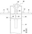
도 5는 도 2 에 도시된 스프레이 밸브를 탈기기에 장착한 모습을 나타내는 부분 측단면도이다.
도 6 및 도 7은 본 발명의 일 실시예에 따른 스프레이 밸브가 구동하는 모습을 나타낸 측단면 모식도이다.1 is a perspective view showing a conventional spray valve.
2 is a side sectional view showing a spray valve according to an embodiment of the present invention.
Fig. 3 is a plan view showing excerpts of only the nozzle piston and the spray valve cylinder shown in Fig. 2;
Fig. 4 is a plan view according to still another embodiment shown exclusively of the nozzle piston and the spray valve cylinder shown in Fig. 2;
5 is a partial side sectional view showing a state in which the spray valve shown in Fig. 2 is mounted on the deaerator.
6 and 7 are side sectional schematic views showing a state in which a spray valve is driven according to an embodiment of the present invention.
이하 도면을 참조하여 본 발명의 바람직한 실시예를 상세히 설명하기로 한다. 이에 앞서, 본 명세서 및 청구범위에 사용된 용어나 단어는 통상적이거나 사전적인 의미로 한정하여 해석되어서는 아니되며, 본 발명의 기술적 사상에 부합하는 의미와 개념으로 해석되어야 한다.Hereinafter, preferred embodiments of the present invention will be described in detail with reference to the drawings. Prior to the description, terms and words used in the present specification and claims should not be construed as limited to ordinary or dictionary meanings and should be construed in accordance with the technical concept of the present invention.
본 명세서 전체에서, 어떤 부재가 다른 부재 "상에" 위치하고 있다고 할 때, 이는 어떤 부재가 다른 부재에 접해 있는 경우뿐 아니라 두 부재 사이에 또 다른 부재가 존재하는 경우도 포함한다.본 명세서 전체에서, 어떤 부분이 어떤 구성요소를 "포함" 한다고 할 때, 이는 특별히 반대되는 기재가 없는 한 다른 구성요소를 제외하는 것이 아니라 다른 구성 요소를 더 포함할 수 있는 것을 의미한다.Throughout this specification, when a member is " on " another member, this includes not only when the member is in contact with another member, but also when there is another member between the two members. Throughout this specification, when an element is referred to as " including " an element, it is understood that it may include other elements as well, without departing from the other elements unless specifically stated otherwise.
도 2에는 본 발명의 일 실시예에 따른 스프레이 밸브를 나타내는 측단면도가 도시되어 있고, 도 3에는 도 2에 도시된 노즐 피스톤과 스프레이 밸브 실린더만은 발췌하여 나타낸 평면도가 도시되어 있다.FIG. 2 is a side sectional view showing a spray valve according to an embodiment of the present invention, and FIG. 3 is a plan view showing only the nozzle piston and the spray valve cylinder shown in FIG. 2 in an excerpt.
우선 도 2를 참조하면, 본 실시예에 따른 스프레이 밸브(100)는, 스프레이 타입 탈기기의 압력용기(20) 내부로 인입되어 압력용기(20) 내부 상방으로 소정 높이만큼 연장되어 설치된 급수유입관(30)의 상단부에 장착되고, 급수유입관(30)으로부터 제공되는 급수를 압력용기(20) 내부로 분사하는 스프레이 밸브로서, 종래 기술에 따른 스프레이 밸브의 문제점을 해결할 수 있다.Referring to FIG. 2, the
본 실시예에 따른 스프레이 밸브(100)는, 특정구조의 스프레이 밸브 실린더(110), 노즐 피스톤(120) 및 탄성부재(130)를 구비함으로써, 급수 분사 면적 및 분사 각도를 넓힐 수 있어 종래 기술 대비 탈기 효율을 현저히 향상시킬 수 있으며, 탈기기에 장착되는 스프레이 밸브의 수량을 감소시킬 수 있고, 급수유입관으로부터 공급되는 급수의 압력에 따라 분사량을 조절할 수 있는 구조를 포함하는 스프레이 밸브를 제공할 수 있다.The
이하에서는 본 실시예에 따른 스프레이 밸브(100)를 구성하고 있는 각 구성에 대해 상세히 설명하기로 한다.Hereinafter, each configuration of the
본 실시예에 따른 스프레이 밸브 실린더(110)는, 하부면이 개방된 원통형 실린더 구조일 수 있다.The
이때, 개방된 하부면은 급수유입관(30)의 상단부와 연통되어, 급수유입관(30)으로부터 제공되는 급수를 공급받을 수 있다.At this time, the opened lower surface communicates with the upper end of the water supply inlet pipe (30) to receive the water supply water supplied from the water supply inlet pipe (30).
스프레이 밸브 실린더(110)의 내부에는, 노즐 피스톤(120)이 상하 방향 이동 가능하도록 내부 슬라이딩 공간이 마련될 수 있다.Inside the
또한, 스프레이 밸브 실린더(110)의 외부면에는, 도 2에 도시된 바와 같이, 상하 방향 일정 간격으로 분사관통구(111)가 다수 형성될 수 있다.As shown in FIG. 2, on the outer surface of the
한편, 노즐 피스톤(120)은, 스프레이 밸브 실린더(110)의 내부면에 상하 방향 이동 가능하도록 장착될 수 있다. 이때, 노즐 피스톤(120)은 급수유입관(30)으로부터 유입되는 수압에 의해 상방으로 위치변경될 수 있다.On the other hand, the
본 실시예에 따른 노즐 피스톤(120)은, 도 2 및 도3에 도시된 바와 같이, 하부판(122), 연결부(123) 및 상부판(124)을 포함하는 구성일 수 있다.The
구체적으로, 하부판(122)은, 급수유입관(30)으로부터 유입되는 수압을 받아 상방으로 위치변경되고, 스프레이 밸브 실린더(110)의 내부면과 대응되는 구조의 평면구조를 가지는 판상형 구조일 수 있다.Specifically, the
연결부(123)는, 하부판(122)과 상부판(124) 사이에 장착되어, 하부판(122)과 상부판(124)을 서로 소정 거리만큼 이격시켜 고정시킬 수 있다. 이때, 연결부(123)는, 상부판(124)과 하부판(122) 사이에 장착되는 판상형 구조, 원기둥 구조 또는 다각기둥 구조일 수 있다. 경우에 따라서, 연결부(123)는, 스프레이 밸브 실린더(110)의 내부 구조와 대응되는 구조의 실린더 구조일 수 있다.The
상부판(124)는, 연결부(123)의 상단에 장착되고, 탄성부재(130)로부터 제공되는 탄성력을 연결부(123)를 통해 하부판(122)에 전달할 수 있다.The
경우에 따라서, 도 3에 도시된 바와 같이, 노즐 피스톤(120)의 외주면에는 피스톤링(piston ring, 121)을 장착할 수 있다. 설계자의 의도 또는 사용자의 의도에 따라 노즐 피스톤(120)의 외주면에는 피스톤링, 가스켓 또는 오링이 장착될 수 있다. 이 경우, 노즐 피스톤이 상하방향 움직임 과정 중에도 급수의 누출을 방지할 수 있다.3, a
경우에 따라서, 도 4에 도시된 바와 같이, 스프레이 밸브 실린더(110)의 내부면에는 노즐 피스톤(120)의 외주면에 형성된 돌기부(125)와 대응되는 형상의 만입부(115)가 상하 방향으로 형성될 수 있다. 또한, 노즐 피스톤(120)의 외주면에는 스프레이 밸브 실린더(110)의 내부면에 형성된 만입부(115)에 안착되는 돌기부(125)가 형성되어, 노즐 피스톤(120)의 상하 방향 움직임을 가이드할 수 있다.4, a
한편, 스프레이 밸브 실린더(110)의 상부에는, 노즐 피스톤(120)의 상하 방향 이동에 따라 공기가 출입할 수 있는 벤트홀(vent hole, 114)이 형성될 수 있다. 따라서, 본 실시예에 따른 스프레이 밸브(100)에 따르면, 노즐 피스톤(120)의 상하 방향 이동에 따라 공기가 스프레이 밸브 실린더(110)의 내부를 자유롭게 출입할 수 있도록 하여, 노즐 피스톤(120)의 상하 방향 움직임을 자연스럽게 유도할 수 있다.A
탄성부재(130)는, 스프레이 밸브 실린더(110)의 내부 상부면과 노즐 피스톤(120)의 상부면 사이에 장착되어 노즐 피스톤(120)을 하방으로 소정 크기의 가압력으로 가압할 수 있다.The
본 실시예에 따른 탄성부재(130)는 상하방향 압축력에 대항하여 소정 크기의 탄성복원력을 발현할 수 있는 부재라면 특별히 제한되는 것은 아니며, 예를 들어 좌우 편심을 안정적으로 방지할 수 있는 이중 코일스프링일 수 있다.The
경우에 따라서, 도 2에 도시된 바와 같이, 스프레이 밸브 실린더(110)의 상부에는, 회전동작에 의해 상하 방향으로 위치 변경되는 상하조절 핸들(140)이 장착될 수 있다. 이때, 상하조절 핸들(140)의 하단부에는 탄성부재(130)의 상단부와 결속될 수 있다.2, a vertically
이 경우, 탄성부재(130)를 통해 노즐 피스톤(120)에 인가되는 가압력의 크기를 조절할 수 있는 상하조절 핸들(140)을 구비함으로써, 급수유입관(30)으로부터 유입되는 급수의 수압에 따라 개방되는 분사관통구(111)의 수량을 손쉽게 조절할 수 있고, 결과적으로 급수유입관(30)에 인가되는 수압을 고려하여 운용자의 의도에 따라 급수의 분사량을 손쉽게 조절할 수 있다.In this case, since the vertical adjustment handle 140 is provided to adjust the magnitude of the pressing force applied to the
도 5에는 도 2 에 도시된 스프레이 밸브를 탈기기에 장착한 모습을 나타내는 부분 측단면도가 도시되어 있고, 도 6 및 도 7에는 본 발명의 일 실시예에 따른 스프레이 밸브가 구동하는 모습을 나타낸 측단면 모식도가 도시되어 있다.FIG. 5 is a partial side cross-sectional view showing a state in which the spray valve shown in FIG. 2 is mounted on the deaerator, and FIGS. 6 and 7 show the spray valve according to the embodiment of the present invention A schematic cross-sectional view is shown.
이들 도면을 참조하면, 본 실시예에 따른 스프레이 밸브 실린더(110)의 외주면에는 압력용기(20)와 결속되는 구조의 결속체결부(112)가 장착될 수 있다.Referring to these figures, the outer circumferential surface of the
본 실시예에 따른 스프레이 밸브(100)는, 스프레이 밸브 실린더(110)의 외주면에 압력용기(20)와 결속되는 구조의 결속체결부(112)가 마련되어 있어, 탈기기 제작 시 손쉽게 스프레이 밸브(100)를 조립할 수 있고, 손쉽게 부착 및 탈거 할 수 있어 손쉽게 유지 관리하여 운용할 수 있다.The
도 6 및 도 7에 도시된 바와 같이, 급수유입관(30)으로부터 유입되는 수압에 의해 상방으로 위치변경되는 노즐 피스톤(120) 및 외부면에 상하 방향 일정 간격으로 분사관통구(111)가 다수 형성된 스프레이 밸브 실린더(110)를 구비함으로써, 급수유입관(30)으로부터 유입되는 급수의 수압에 따라 노즐 피스톤(120)의 상방 위치 변경량이 변경된다.6 and 7, there are provided a
급수유입관(30)으로부터 유입되는 급수의 수압이 현저히 낮을 경우에는 노즐 피스톤(120)의 위치가 탄성부재(130)의 가압력에 의해 하방에 고정되게 되고, 분사관통구(111)는 폐쇄되어 급수는 분사되지 못한다.When the water pressure of the water supplied from the
급수유입관(30)으로부터 유입되는 급수의 수압이 탄성부재(130)의 하방 가압력을 넘어서기 시작할 경우, 도 6에 도시된 바와 같이, 노즐 피스톤(120)의 위치가 상방으로 위치 변경되게 되고, 스프레이 밸브 실린더(110)의 하부에 형성된 분사관통구(111)의 일부가 개방되게 되며, 급수의 일부가 분사되게 된다.When the water pressure of the water supplied from the water
급수유입관(30)으로부터 유입되는 급수의 수압이 탄성부재(130)의 하방 가압력을 월등히 넘어설 경우, 도 7에 도시된 바와 같이, 노즐 피스톤(120)의 위치가 상방으로 최대로 위치 변경되게 되고, 스프레이 밸브 실린더(110)의 하부에 형성된 분사관통구(111)의 모두가 개방되게 되며, 급수가 모든 분사관통구(111)를 통해 분사되게 된다.When the water pressure of the water supplied from the water
결과적으로, 본 실시예에 따른 스프레이 밸브(100)는, 급수유입관(30)으로부터 제공되는 급수의 압력에 따라, 분사관통구(111)의 개방 수량을 조절할 수 있어, 결과적으로 탈기기의 압력용기(20) 내부로 분사되는 급수 분사량을 손쉽게 조절할 수 있다.As a result, the
경우에 따라서, 스프레이 밸브 실린더(110)의 외부면에 형성된 분사관통구(111)는, 스프레이 밸브 실린더(110)의 외부면을 기준으로 측방으로 소정 각도만큼 기울어져 형성될 수 있다. 이 경우, 급수유입관(30)으로부터 제공된 급수의 분사 각도를 다양화 하여 탈기 효율을 극대화 시킬 수 있으며, 분사관통구의 형성 방향을 설계자의 의도에 따라 적절히 변경함으로써, 탈기 효율을 적절히 변경시킬 수 있다.The spray through
이상의 본 발명의 상세한 설명에서는 그에 따른 특별한 실시예에 대해서만 기술하였다. 하지만 본 발명은 상세한 설명에서 언급되는 특별한 형태로 한정되는 것이 아닌 것으로 이해되어야 하며, 오히려 첨부된 청구범위에 의해 정의되는 본 발명의 정신과 범위 내에 있는 모든 변형물과 균등물 및 대체물을 포함하는 것으로 이해되어야 한다.In the foregoing detailed description of the present invention, only specific embodiments thereof have been described. It is to be understood, however, that the invention is not to be limited to the specific forms thereof, which are to be considered as being limited to the specific embodiments, but on the contrary, the intention is to cover all modifications, equivalents, and alternatives falling within the spirit and scope of the invention as defined by the appended claims. .
즉, 본 발명은 상술한 특정의 실시예 및 설명에 한정되지 아니하며, 청구범위에서 청구하는 본 발명의 요지를 벗어남이 없이 본 발명이 속하는 기술 분야에서 통상의 지식을 가진 자라면 누구든지 다양한 변형 실시가 가능하며, 그와 같은 변형은 본 발명의 보호 범위 내에 있게 된다.That is, the present invention is not limited to the above-described specific embodiment and description, and various changes and modifications may be made without departing from the spirit and scope of the invention as defined in the appended claims. And such variations are within the scope of protection of the present invention.
10: 종래 기술에 따른 스프레이 밸브
11: 플랜지
12: 축
13: 제 1 스프링 지지대
14: 고깔형상의 개폐부
15: 삼각대
16: 제 2 스프링 지지대
17: 압축코일 스프링
20: 압력용기(shell)
30: 급수유입관
100: 스프레이 밸브
110: 스프레이 밸브 실린더
111: 분사관통구
112: 결속체결부
114: 벤트홀(vent hole)
115: 만입부
120: 노즐 피스톤
121: 피스톤링(piston ring)
122: 하부판
123: 연결부
124: 상부판
125: 돌기부
130: 탄성부재
140: 상하조절 핸들10: Spray valve according to the prior art
11: Flange
12: Axis
13: first spring support
14: opening /
15: Tripod
16: second spring support
17: Compression coil spring
20: pressure vessel (shell)
30: Water inlet pipe
100: Spray valve
110: Spray valve cylinder
111: injection hole
112:
114: vent hole
115: indentation
120: nozzle piston
121: piston ring
122:
123: Connection
124:
125: protrusion
130: elastic member
140: Vertical adjustment handle
Claims (12)
Translated fromKorean하부면이 개방된 원통형 실린더 구조이고, 하부면은 급수유입관(30)의 상단부와 연통되고, 노즐 피스톤(120)이 상하 방향 이동 가능하도록 내부 슬라이딩 공간이 마련되어 있으며, 외부면에 상하 방향 일정 간격으로 분사관통구(111)가 다수 형성된 스프레이 밸브 실린더(110);
상기 스프레이 밸브 실린더(110)의 내부면에 상하 방향 이동 가능하도록 장착되고, 급수유입관(30)으로부터 유입되는 수압에 의해 상방으로 위치변경되는 노즐 피스톤(120); 및
상기 스프레이 밸브 실린더(110)의 내부 상부면과 노즐 피스톤(120)의 상부면 사이에 장착되어 노즐 피스톤(120)을 하방으로 소정 크기의 가압력으로 가압하는 탄성부재(130);
를 포함하고,
상기 노즐 피스톤(120)은,
급수유입관(30)으로부터 유입되는 수압을 받아 상방으로 위치변경되고, 스프레이 밸브 실린더(110)의 내부면과 대응되는 구조의 평면구조를 가지는 판상형 구조의 하부판(122);
상기 하부판(122)과 상부판(124) 사이에 장착되어, 하부판(122)과 상부판(124)을 서로 소정 거리만큼 이격시켜 고정시키는 연결부(123); 및
상기 연결부(123)의 상단에 장착되고, 탄성부재(130)로부터 제공되는 탄성력을 연결부(123)를 통해 하부판(122)에 전달하는 상부판(124);
을 포함하는 것을 특징으로 하는 스프레이 밸브(100).
The water supply pipe 30 is installed at the upper end of the water inlet pipe 30 which is drawn into the pressure vessel 20 of the spray type deaerating apparatus 20 and extends upward by a predetermined height above the interior of the pressure vessel 20, To the inside of the pressure vessel (20)
A lower surface communicating with the upper end of the water supply inlet pipe 30, an inner sliding space provided to allow the nozzle piston 120 to move in the up and down direction, A spray valve cylinder 110 having a plurality of spray through holes 111 formed therein;
A nozzle piston 120 mounted on the inner surface of the spray valve cylinder 110 so as to be movable up and down and to be displaced upward by the water pressure introduced from the water supply inlet pipe 30; And
An elastic member 130 mounted between an inner upper surface of the spray valve cylinder 110 and an upper surface of the nozzle piston 120 to press the nozzle piston 120 downward with a predetermined urging force;
Lt; / RTI >
The nozzle piston (120)
A bottom plate 122 of a plate-like structure having a planar structure of a structure corresponding to the inner surface of the spray valve cylinder 110, the bottom plate 122 being displaced upward by receiving hydraulic pressure from the water inlet pipe 30;
A connecting part 123 mounted between the bottom plate 122 and the top plate 124 to fix the bottom plate 122 and the top plate 124 by a predetermined distance apart; And
An upper plate 124 mounted on an upper end of the connection part 123 and transmitting an elastic force provided from the elastic member 130 to the lower plate 122 through a connection part 123;
(100). ≪ / RTI >
상기 스프레이 밸브 실린더(110)의 외주면에는 압력용기(20)와 결속되는 구조의 결속체결부(112)가 장착되어 있는 것을 특징으로 하는 스프레이 밸브.
The method according to claim 1,
Wherein the spray valve cylinder (110) is mounted on the outer circumferential surface thereof with a binding engagement portion (112) structured to be coupled to the pressure vessel (20).
상기 노즐 피스톤(120)의 외주면에는 피스톤링(piston ring, 121), 가스켓(gasket) 또는 오링(O-ring)이 장착되는 것을 특징으로 하는 스프레이 밸브.
The method according to claim 1,
Wherein a piston ring (121), a gasket or an O-ring is mounted on an outer peripheral surface of the nozzle piston (120).
상기 스프레이 밸브 실린더(110)의 내부면에는 노즐 피스톤(120)의 외주면에 형성된 돌기부(125)와 대응되는 형상의 만입부(115)가 상하 방향으로 형성되어 있고,
상기 노즐 피스톤(120)의 외주면에는 스프레이 밸브 실린더(110)의 내부면에 형성된 만입부(115)에 안착되는 돌기부(125)가 형성되어, 노즐 피스톤(120)의 상하 방향 움직임을 가이드 하는 것을 특징으로 하는 스프레이 밸브.
The method according to claim 1,
A depression 115 having a shape corresponding to the protrusion 125 formed on the outer circumferential surface of the nozzle piston 120 is formed on the inner surface of the spray valve cylinder 110 in a vertical direction,
The nozzle piston 120 has a protrusion 125 formed on the outer circumferential surface of the nozzle piston 120 to be seated on the indented portion 115 formed on the inner surface of the spray valve cylinder 110 to guide the nozzle piston 120 in the vertical direction Spray valve with.
상기 스프레이 밸브 실린더(110)의 상부에는, 노즐 피스톤(120)의 상하 방향 이동에 따라 공기가 출입할 수 있는 벤트홀(vent hole, 114)이 형성되어 있는 것을 특징으로 하는 스프레이 밸브.
The method according to claim 1,
Wherein a vent hole (114) is formed in an upper portion of the spray valve cylinder (110) to allow air to flow in and out of the nozzle piston (120) as the nozzle piston (120) moves up and down.
상기 스프레이 밸브 실린더(110)의 외부면에 형성된 분사관통구(111)는, 스프레이 밸브 실린더(110)의 외부면을 기준으로 측방으로 소정 각도만큼 기울어져 형성되어 있는 것을 특징으로 하는 스프레이 밸브.
The method according to claim 1,
Wherein a spray through hole (111) formed on the outer surface of the spray valve cylinder (110) is formed to be laterally slanted by a predetermined angle with respect to an outer surface of the spray valve cylinder (110).
상기 연결부(123)는, 상부판(124)과 하부판(122) 사이에 장착되는 판상형 구조, 원기둥 구조 또는 다각기둥 구조인 것을 특징으로 하는 스프레이 밸브.
The method according to claim 1,
Wherein the connection part (123) is a plate-like structure, a cylindrical structure, or a polygonal columnar structure mounted between the upper plate (124) and the lower plate (122).
상기 연결부(123)는, 스프레이 밸브 실린더(110)의 내부 구조와 대응되는 구조의 실린더 구조인 것을 특징으로 하는 스프레이 밸브.
The method according to claim 1,
Wherein the connection part (123) is a cylinder structure having a structure corresponding to the internal structure of the spray valve cylinder (110).
상기 탄성부재(130)는 이중 코일스프링인 것을 특징으로 하는 스프레이 밸브.
The method according to claim 1,
Wherein the elastic member (130) is a double coil spring.
상기 스프레이 밸브 실린더(110)의 상부에는, 회전동작에 의해 상하 방향으로 위치 변경되는 상하조절 핸들(140)이 장착되고,
상기 상하조절 핸들(140)의 하단부에는 탄성부재(130)의 상단부와 결속되는 것을 특징으로 하는 스프레이 밸브.
The method according to claim 1,
A vertically adjustable handle 140 is mounted on the upper portion of the spray valve cylinder 110,
Wherein the upper end of the elastic member (130) is engaged with the lower end of the upper and lower adjustment handle (140).
A deaerator comprising a spray valve (100) according to any one of claims 1 to 6 and 8 to 11.
Priority Applications (1)
| Application Number | Priority Date | Filing Date | Title |
|---|---|---|---|
| KR1020160134069AKR101920705B1 (en) | 2016-10-17 | 2016-10-17 | Spray Valve Having Structure for Controlling Quantity of Water, and Deaerator Having the Same |
Applications Claiming Priority (1)
| Application Number | Priority Date | Filing Date | Title |
|---|---|---|---|
| KR1020160134069AKR101920705B1 (en) | 2016-10-17 | 2016-10-17 | Spray Valve Having Structure for Controlling Quantity of Water, and Deaerator Having the Same |
Publications (2)
| Publication Number | Publication Date |
|---|---|
| KR20180041842A KR20180041842A (en) | 2018-04-25 |
| KR101920705B1true KR101920705B1 (en) | 2018-11-21 |
Family
ID=62088541
Family Applications (1)
| Application Number | Title | Priority Date | Filing Date |
|---|---|---|---|
| KR1020160134069AActiveKR101920705B1 (en) | 2016-10-17 | 2016-10-17 | Spray Valve Having Structure for Controlling Quantity of Water, and Deaerator Having the Same |
Country Status (1)
| Country | Link |
|---|---|
| KR (1) | KR101920705B1 (en) |
Families Citing this family (1)
| Publication number | Priority date | Publication date | Assignee | Title |
|---|---|---|---|---|
| CN109612777B (en)* | 2019-01-29 | 2023-08-11 | 佛山科学技术学院 | A water sampling device |
Citations (3)
| Publication number | Priority date | Publication date | Assignee | Title |
|---|---|---|---|---|
| JP2000005644A (en)* | 1998-06-19 | 2000-01-11 | Mitsubishi Heavy Ind Ltd | Injection nozzle |
| JP5312775B2 (en)* | 2007-11-27 | 2013-10-09 | 株式会社富士機械工作所 | Tube welding equipment |
| JP2016161148A (en)* | 2015-02-26 | 2016-09-05 | 三菱日立パワーシステムズ株式会社 | Spray nozzle and deaerator |
- 2016
- 2016-10-17KRKR1020160134069Apatent/KR101920705B1/enactiveActive
Patent Citations (3)
| Publication number | Priority date | Publication date | Assignee | Title |
|---|---|---|---|---|
| JP2000005644A (en)* | 1998-06-19 | 2000-01-11 | Mitsubishi Heavy Ind Ltd | Injection nozzle |
| JP5312775B2 (en)* | 2007-11-27 | 2013-10-09 | 株式会社富士機械工作所 | Tube welding equipment |
| JP2016161148A (en)* | 2015-02-26 | 2016-09-05 | 三菱日立パワーシステムズ株式会社 | Spray nozzle and deaerator |
Also Published As
| Publication number | Publication date |
|---|---|
| KR20180041842A (en) | 2018-04-25 |
Similar Documents
| Publication | Publication Date | Title |
|---|---|---|
| KR101920793B1 (en) | Spray Valve Having Structure for Controlling Quantity of Water, and Deaerator Having the Same | |
| US10012322B2 (en) | Check valve | |
| US20140332097A1 (en) | Flow-volume regulator | |
| US7175157B2 (en) | Fluid controller | |
| US7950624B2 (en) | Water valve apparatus | |
| KR100841234B1 (en) | Chemical liquid valve | |
| KR101907283B1 (en) | Fluid controller | |
| JP2017198386A5 (en) | ||
| KR101920705B1 (en) | Spray Valve Having Structure for Controlling Quantity of Water, and Deaerator Having the Same | |
| KR101920737B1 (en) | Spray Valve Having Structure for Controlling Quantity of Water, and Deaerator Having the Same | |
| KR101869042B1 (en) | Container for Discharging Powder | |
| US9416893B2 (en) | Fluid controller actuator | |
| KR101131122B1 (en) | Leak control trim and valve | |
| KR101920788B1 (en) | Spray Valve Having Structure for Controlling Quantity of Water, and Deaerator Having the Same | |
| KR101535560B1 (en) | Backflow prevention device | |
| JP2003166659A (en) | Relief valve | |
| CN111587054B (en) | Flow adjusting device and liquid cooling rack | |
| KR101793791B1 (en) | Pressure regulate valve device having a flow blocking function | |
| KR101640474B1 (en) | Flow control valve | |
| KR200385261Y1 (en) | A Gas Pressure Regulating Valve | |
| KR200480010Y1 (en) | valve of double plug type | |
| JP5722193B2 (en) | Pressure reducing valve | |
| KR20190004392A (en) | Variable pressure apparatus for electric pressure cooker | |
| RU2559517C2 (en) | Vibration damping spring clamp for pressure regulator | |
| CN119456248A (en) | Spraying device and working method thereof |
Legal Events
| Date | Code | Title | Description |
|---|---|---|---|
| A201 | Request for examination | ||
| PA0109 | Patent application | St.27 status event code:A-0-1-A10-A12-nap-PA0109 | |
| PA0201 | Request for examination | St.27 status event code:A-1-2-D10-D11-exm-PA0201 | |
| E902 | Notification of reason for refusal | ||
| PE0902 | Notice of grounds for rejection | St.27 status event code:A-1-2-D10-D21-exm-PE0902 | |
| E13-X000 | Pre-grant limitation requested | St.27 status event code:A-2-3-E10-E13-lim-X000 | |
| P11-X000 | Amendment of application requested | St.27 status event code:A-2-2-P10-P11-nap-X000 | |
| P13-X000 | Application amended | St.27 status event code:A-2-2-P10-P13-nap-X000 | |
| PG1501 | Laying open of application | St.27 status event code:A-1-1-Q10-Q12-nap-PG1501 | |
| E701 | Decision to grant or registration of patent right | ||
| PE0701 | Decision of registration | St.27 status event code:A-1-2-D10-D22-exm-PE0701 | |
| GRNT | Written decision to grant | ||
| PR0701 | Registration of establishment | St.27 status event code:A-2-4-F10-F11-exm-PR0701 | |
| PR1002 | Payment of registration fee | St.27 status event code:A-2-2-U10-U11-oth-PR1002 Fee payment year number:1 | |
| PG1601 | Publication of registration | St.27 status event code:A-4-4-Q10-Q13-nap-PG1601 | |
| PR1001 | Payment of annual fee | St.27 status event code:A-4-4-U10-U11-oth-PR1001 Fee payment year number:4 | |
| PN2301 | Change of applicant | St.27 status event code:A-5-5-R10-R13-asn-PN2301 St.27 status event code:A-5-5-R10-R11-asn-PN2301 | |
| PR1001 | Payment of annual fee | St.27 status event code:A-4-4-U10-U11-oth-PR1001 Fee payment year number:5 | |
| PR1001 | Payment of annual fee | St.27 status event code:A-4-4-U10-U11-oth-PR1001 Fee payment year number:6 | |
| PR1001 | Payment of annual fee | St.27 status event code:A-4-4-U10-U11-oth-PR1001 Fee payment year number:7 | |
| R18-X000 | Changes to party contact information recorded | St.27 status event code:A-5-5-R10-R18-oth-X000 | |
| PR1001 | Payment of annual fee | St.27 status event code:A-4-4-U10-U11-oth-PR1001 Fee payment year number:8 |