KR101920471B1 - Communication system using wireless power - Google Patents
Communication system using wireless powerDownload PDFInfo
- Publication number
- KR101920471B1 KR101920471B1KR1020110097543AKR20110097543AKR101920471B1KR 101920471 B1KR101920471 B1KR 101920471B1KR 1020110097543 AKR1020110097543 AKR 1020110097543AKR 20110097543 AKR20110097543 AKR 20110097543AKR 101920471 B1KR101920471 B1KR 101920471B1
- Authority
- KR
- South Korea
- Prior art keywords
- envelope
- resonator
- unit
- signal
- target resonator
- Prior art date
- Legal status (The legal status is an assumption and is not a legal conclusion. Google has not performed a legal analysis and makes no representation as to the accuracy of the status listed.)
- Active
Links
Images


Classifications
- H—ELECTRICITY
- H02—GENERATION; CONVERSION OR DISTRIBUTION OF ELECTRIC POWER
- H02J—CIRCUIT ARRANGEMENTS OR SYSTEMS FOR SUPPLYING OR DISTRIBUTING ELECTRIC POWER; SYSTEMS FOR STORING ELECTRIC ENERGY
- H02J50/00—Circuit arrangements or systems for wireless supply or distribution of electric power
- H02J50/10—Circuit arrangements or systems for wireless supply or distribution of electric power using inductive coupling
- H02J50/12—Circuit arrangements or systems for wireless supply or distribution of electric power using inductive coupling of the resonant type
- G—PHYSICS
- G06—COMPUTING OR CALCULATING; COUNTING
- G06K—GRAPHICAL DATA READING; PRESENTATION OF DATA; RECORD CARRIERS; HANDLING RECORD CARRIERS
- G06K19/00—Record carriers for use with machines and with at least a part designed to carry digital markings
- G06K19/06—Record carriers for use with machines and with at least a part designed to carry digital markings characterised by the kind of the digital marking, e.g. shape, nature, code
- G06K19/067—Record carriers with conductive marks, printed circuits or semiconductor circuit elements, e.g. credit or identity cards also with resonating or responding marks without active components
- G06K19/07—Record carriers with conductive marks, printed circuits or semiconductor circuit elements, e.g. credit or identity cards also with resonating or responding marks without active components with integrated circuit chips
- G06K19/0701—Record carriers with conductive marks, printed circuits or semiconductor circuit elements, e.g. credit or identity cards also with resonating or responding marks without active components with integrated circuit chips at least one of the integrated circuit chips comprising an arrangement for power management
- G06K19/0712—Record carriers with conductive marks, printed circuits or semiconductor circuit elements, e.g. credit or identity cards also with resonating or responding marks without active components with integrated circuit chips at least one of the integrated circuit chips comprising an arrangement for power management the arrangement being capable of triggering distinct operating modes or functions dependent on the strength of an energy or interrogation field in the proximity of the record carrier
Landscapes
- Engineering & Computer Science (AREA)
- Physics & Mathematics (AREA)
- Computer Hardware Design (AREA)
- Microelectronics & Electronic Packaging (AREA)
- Electromagnetism (AREA)
- General Physics & Mathematics (AREA)
- Theoretical Computer Science (AREA)
- Computer Networks & Wireless Communication (AREA)
- Power Engineering (AREA)
- Near-Field Transmission Systems (AREA)
Abstract
Translated fromKoreanDescription
Translated fromKorean기술분야는 무선 전력을 이용하여 통신을 수행하는 장치 및 시스템에 관한 것이다.The art is directed to devices and systems for performing communications using wireless power.
무선 전력전송에 대한 연구는 휴대기기를 포함한 다양한 전기기기의 폭발적 증가로 인한 유선 전력 공급의 불편 증가 및 기존 배터리(battery) 용량의 한계 봉착 등을 극복하기 위해 시작되었다. 그 중에서도 근거리 무선 전력 전송에 대한 연구가 집중되고 있다. 근거리 무선 전력 전송이라 함은 동작 주파수에서 파장의 길이에 비해 송수신 코일간의 거리가 충분히 작은 경우를 의미한다. 공진 특성을 이용하는 무선 전력 송수신 시스템은 전력을 공급하는 소스와 전력을 공급받는 타겟을 포함할 수 있다. 무선 전력을 전송하고 수신하는 과정에서 소스와 타겟은 제어 정보를 공유할 필요가 있다. 또한, 제어 정보를 공유함에 있어서, 소스와 타겟 간에 상호 동기가 필요하다.Research on wireless power transmission has begun to overcome the inconveniences of wired power supply due to explosive increase of various electric devices including portable devices and limitations of existing battery capacity. Among them, research on near field wireless power transmission is concentrated. Near-field wireless power transmission means that the distance between the transmitting and receiving coils is sufficiently smaller than the wavelength length at the operating frequency. A wireless power transmission / reception system using resonance characteristics may include a power-supplying source and a power-receiving target. In transmitting and receiving wireless power, the source and target need to share control information. Further, in sharing control information, mutual synchronization between the source and the target is required.
일 측면에 있어서, 무선 전력을 이용한 통신 장치는 소스 공진기와의 상호 공진을 통하여 타겟 공진기에 저장된 에너지의 파형에서 포락선의 기울기를 계산하는 계산부 및 상기 계산된 포락선의 기울기가 최대가 되는 시점을 상기 소스 공진기와 상기 타겟 공진기 간의 상호 공진 시작점으로 추정하는 추정부를 포함한다.In one aspect of the present invention, a communication apparatus using wireless power includes a calculation unit for calculating a slope of an envelope in a waveform of energy stored in a target resonator through mutual resonance with a source resonator, and a calculation unit for calculating a time at which the calculated slope of the envelope becomes maximum And an estimator for estimating a resonance starting point between the source resonator and the target resonator.
다른 일 측면에 있어서, 무선 전력을 이용한 통신 장치는 상기 타겟 공진기에 인가되는 전류 또는 전압의 파형에서 포락선을 검출하는 포락선 검출부를 더 포함할 수 있다.In another aspect, the communication apparatus using wireless power may further include an envelope detecting unit that detects an envelope in a waveform of a current or voltage applied to the target resonator.
상기 계산부는 상기 검출된 포락선에서 일정한 간격을 가지는 두 지점 간의 기울기를 계산할 수 있다.The calculation unit may calculate a slope between two points having a predetermined interval in the detected envelope.
상기 계산부는 상기 검출된 포락선의 각 지점에서 접선의 기울기를 계산할 수 있다.The calculation unit may calculate the slope of the tangent line at each point of the detected envelope.
다른 일 측면에 있어서, 무선 전력을 이용한 통신 장치는 설정된 슬라이딩 윈도우 구간에서 상기 타겟 공진기에 인가되는 신호의 세기를 측정하여 상기 소스 공진기로부터 전송된 프레임을 검출하는 프레임 검출부를 더 포함할 수 있다.In another aspect, the communication apparatus using wireless power may further include a frame detector for measuring a strength of a signal applied to the target resonator in a set sliding window period and detecting a frame transmitted from the source resonator.
상기 프레임은 상기 소스 공진기로부터 전송된 프레임의 검출, 상기 소스 공진기와 상기 타겟 공진기 간의 상기 상호 공진 시작점 추정 및 상기 타겟 공진기에 저장된 에너지의 채득(capture) 포인트 검출에 사용되는 프리앰블 영역; 및 상기 소스 공진기로부터 상기 타겟 공진기로의 에너지 전송 및 데이터 전송에 사용되는 바디 영역을 포함할 수 있다.The frame including a preamble region used for detecting a frame transmitted from the source resonator, for estimating the mutual resonance starting point between the source resonator and the target resonator, and for detecting a capture point of energy stored in the target resonator; And a body region used for energy transmission and data transmission from the source resonator to the target resonator.
다른 일 측면에 있어서, 무선 전력을 이용한 통신 장치는 상기 타겟 공진기와 상기 소스 공진기가 상호 공진을 시작하기 이전 상태인, 아이들 리슨(Idle listen) 상태에서는, 상기 소스 공진기가 에너지를 전송하면 상호 공진을 통하여 바로 에너지를 수신할 수 있도록, 상기 타겟 공진기를 활성화(activate) 된 상태로 유지시키는 제어부를 더 포함할 수 있다.In another aspect, in a communication device using radio power, in the idle listening state in which the target resonator and the source resonator start mutual resonance, when the source resonator transmits energy, mutual resonance The target resonator may further include a control unit for maintaining the target resonator in an activated state so as to receive energy directly.
다른 일 측면에 있어서, 무선 전력을 이용한 통신 장치는 상기 설정된 슬라이딩 윈도우 구간을 포함하는 특정 구간에서 상기 타겟 공진기에 인가되는 신호들을 축적하는 신호 축적부를 더 포함할 수 있다.In another aspect, the communication apparatus using wireless power may further include a signal accumulator for accumulating signals applied to the target resonator in a specific section including the set sliding window period.
상기 계산부는 상기 축적된 신호들에서 검출된 포락선의 기울기를 계산할 수 있다.The calculator may calculate the slope of the envelope detected in the accumulated signals.
상기 포락선 검출부는 상기 전류 또는 상기 전압을 입력으로 하여 포락선 검출용 아날로그 회로의 출력으로부터 상기 포락선을 획득할 수 있다.The envelope detector may receive the current or the voltage as input and obtain the envelope from the output of the analog circuit for envelope detection.
상기 포락선 검출부는 상기 전압 또는 상기 전류로부터 아날로그-디지털 변환(ADC) 샘플링 된 신호를 공진 주파수의 특정 신호 파형 중의 하나와 곱하여 하향 변환(down conversion)된 신호를 생성하는 하향 변환부, 상기 하향 변환된 신호를 이산 푸리에 변환 또는 고속 푸리에 변환하여 주파수 영역 신호로 변환하는 변환부, 상기 주파수 영역 신호에 저역 통과 필터링을 수행하여 하모닉 성분이 제거된 신호를 생성하는 필터링부 및 상기 하모닉 성분이 제거된 신호를 이산 푸리에 역변환 또는 고속 푸리에 역변환하여 시간 영역 신호로 변환하는 역변환부를 포함할 수 있다.The envelope detector includes a down converter for multiplying an analog-to-digital (ADC) sampled signal from the voltage or the current by one of a specific signal waveform of a resonance frequency to generate a down-converted signal, A filtering unit for performing a low-pass filtering on the frequency-domain signal to generate a signal from which a harmonic component has been removed, and a filtering unit for removing the harmonic-component- And performing inverse Fourier inverse transform or inverse fast Fourier transform to inverse Fourier transform.
상기 포락선 검출부는 상기 전압 또는 상기 전류로부터 아날로그-디지털 변환(ADC) 샘플링 된 신호를 이산 푸리에 변환 또는 고속 푸리에 변환하여 주파수 영역 신호로 변환하는 변환부, 상기 주파수 영역 신호를 소정의 주파수만큼 순환 이동(circular shift)시키는 순환 이동부, 상기 순환 이동된 신호에 저역 통과 필터링을 수행하여 하모닉 성분이 제거된 신호를 생성하는 필터링부 및 상기 하모닉 성분이 제거된 신호를 이산 푸리에 역변환 또는 고속 푸리에 역변환하여 시간 영역 신호로 변환하는 역변환부를 포함할 수 있다.The envelope detector includes a converter for performing a discrete Fourier transform or a fast Fourier transform on an analog-to-digital (ADC) sampled signal from the voltage or the current to convert the sampled signal into a frequency domain signal, a filtering unit for performing a low-pass filtering on the cyclically shifted signal to generate a signal from which the harmonic component has been removed, and a discrete Fourier inverse fast Fourier transform or inverse fast Fourier transform Signal into an inverse transform signal.
상기 포락선 검출부는 상기 전압 또는 상기 전류로부터 아날로그-디지털 변환(ADC) 샘플링 된 신호를 공진 주파수의 특정 신호 파형 중의 하나와 곱하여 하향 변환(down conversion)된 신호를 생성하는 하향 변환부 및 시간 영역에서 컨볼루션을 통해 상기 하향 변환된 신호에 저역 통과 필터링을 수행하여, 하모닉 성분이 제거된 신호를 생성하는 필터링부를 포함할 수 있다.The envelope detector may include a down-converter for multiplying an analog-to-digital (ADC) sampled signal from the voltage or the current by one of a specific signal waveform of a resonance frequency to generate a down-converted signal, And a filtering unit that performs low-pass filtering on the down-converted signal through the filter to generate a signal from which the harmonic component is removed.
다른 일 측면에 있어서, 무선 전력을 이용한 통신 장치는 상기 검출된 포락선의 크기가 피크(peak)인 피크 포인트를 검출하는 피크 포인트 검출부 및 상기 검출된 피크 포인트에서 상기 타겟 공진기에 저장된 에너지를 채득(capture)하는 채득부를 더 포함할 수 있다.In another aspect, a communication apparatus using radio power includes a peak point detection unit for detecting a peak point where the size of the detected envelope is a peak, and a peak point detection unit for detecting an energy stored in the target resonator at the detected peak point And a receiving unit for receiving the data.
다른 일 측면에 있어서, 무선 전력을 이용한 통신 장치는 상기 상호 공진 시작점을 기준으로 하여 상기 타겟 공진기의 자기 공진을 활성화 시켜, 상기 소스 공진기로부터 전송된 에너지를 수신하는 수신부, 상기 수신한 에너지의 양에 기초하여 상기 소스 공진기가 전송하는 정보를 복조하는 복조부 및 상기 상호 공진 시작점을 기준으로 하여, 상기 소스 공진기와의 상호 공진 여부에 따라 상기 소스 공진기로 전송하는 정보를 변조하는 변조부를 더 포함할 수 있다.In another aspect, a communication apparatus using radio power includes a receiving section for activating self resonance of the target resonator on the basis of the mutual resonance start point and receiving energy transmitted from the source resonator, And a modulator for modulating information to be transmitted to the source resonator according to mutual resonance with the source resonator on the basis of the mutual resonance starting point as a reference, have.
일 측면에 있어서, 무선 전력을 이용한 통신 방법은 소스 공진기와의 상호 공진을 통하여 타겟 공진기에 저장된 에너지의 파형에서 포락선의 기울기를 계산하는 단계 및 상기 계산된 포락선의 기울기가 최대가 되는 시점을 상기 소스 공진기와 상기 타겟 공진기 간의 상호 공진 시작점으로 추정하는 단계를 포함한다.In one aspect, a communication method using radio power includes the steps of calculating a slope of an envelope in a waveform of energy stored in a target resonator through mutual resonance with a source resonator, and calculating a time point at which the calculated slope of the envelope becomes maximum, Resonance starting point between the resonator and the target resonator.
다른 일 측면에 있어서, 무선 전력을 이용한 통신 방법은 상기 타겟 공진기에 인가되는 전류 또는 전압의 파형에서 포락선을 검출하는 단계를 더 포함할 수 있다.In another aspect, a communication method using wireless power may further include detecting an envelope in a waveform of a current or voltage applied to the target resonator.
상기 계산하는 단계는 상기 검출된 포락선에서 일정한 간격을 가지는 두 지점 간의 기울기를 계산할 수 있다.The calculating step may calculate a slope between two points having a predetermined interval in the detected envelope.
다른 일 측면에 있어서, 무선 전력을 이용한 통신 방법은 상기 타겟 공진기와 상기 소스 공진기가 상호 공진을 시작하기 이전 상태인, 아이들 리슨(Idle listen) 상태에서는, 상기 소스 공진기가 에너지를 전송하면 상호 공진을 통하여 바로 에너지를 수신할 수 있도록, 상기 타겟 공진기를 활성화(activate) 된 상태로 유지시키는 단계를 더 포함할 수 있다.According to another aspect of the present invention, in a method of communicating using radio power, in the idle listening state in which the target resonator and the source resonator start mutual resonance, when the source resonator transmits energy, And maintaining the target resonator in an activated state so as to receive the energy directly.
상기 검출된 포락선의 크기가 피크(peak)인 피크 포인트를 검출하는 단계; 및 상기 검출된 피크 포인트에서 상기 타겟 공진기에 저장된 에너지를 채득(capture)하는 단계를 더 포함할 수 있다.Detecting a peak point where the size of the detected envelope is a peak; And capturing energy stored in the target resonator at the detected peak point.
일 측면에 있어서, 무선 전력을 이용한 통신 시스템은 소스 공진기에 저장된 에너지를 상호 공진을 통하여 타겟 공진기로 전송하는 전송부, 상기 상호 공진을 통하여 상기 타겟 공진기에 저장된 에너지의 파형에서 포락선을 검출하는 포락선 검출부, 상기 검출된 포락선의 기울기를 계산하는 계산부 및 상기 계산된 포락선의 기울기가 최대가 되는 시점을 상기 소스 공진기와 상기 타겟 공진기 간의 상호 공진 시작점으로 추정하는 추정부를 포함한다.In one aspect of the present invention, a communication system using radio power includes a transmission unit that transmits energy stored in a source resonator to a target resonator through mutual resonance, an envelope detection unit that detects an envelope from a waveform of energy stored in the target resonator through the mutual resonance, A calculator for calculating a slope of the detected envelope, and an estimator for estimating a time at which the calculated slope of the envelope becomes maximum as a mutual resonance starting point between the source resonator and the target resonator.
타겟 공진기에 저장된 에너지의 파형에서 포락선을 검출하고, 검출된 포락선에서 포락선의 기울기를 계산하여, 기울기가 최대가 되는 시점을 상호 공진의 시작점으로 추정함으로써, 소스 공진기와 타겟 공진기간의 시간 동기가 가능하다.By detecting the envelope in the waveform of the energy stored in the target resonator and calculating the slope of the envelope in the detected envelope, the time synchronization between the source resonator and the target resonance period is possible by estimating the point at which the tilt becomes maximum as the starting point of mutual resonance Do.
보다 구체적으로 소스 공진기가 에너지를 전송하는 시작 시점을 수신단에서 검출하여 상호 공진을 수행하고, 타겟 공진기에 저장되는 에너지가 피크 값을 가지는 시점을 찾아, 저장된 에너지를 채득할 수 있다.More specifically, the starting point at which the source resonator transmits energy is detected at the receiving end to perform mutual resonance, and a time point at which energy stored in the target resonator has a peak value can be found and stored energy can be obtained.
소스 공진기에서 에너지를 전송하는 중간 시점뿐만 아니라 에너지를 전송하기 시작하는 시점에서도 시간 동기의 추정이 가능하다.Time synchronization can be estimated not only at the intermediate point of transmission of energy in the source resonator but also at the point of starting to transmit energy.
도 1은 일실시예에 따른 전력 입력부와 전력 전송부, 수신부와 전력 출력부가 캐패시터 및 스위치에 의하여 물리적으로 분리된 무선 전력을 이용한 통신 시스템의 등가회로를 나타낸 도면이다.
도 2는 일실시예에 따른 전력 충전부와 전송부, 충전부와 전력 출력부가 스위치에 의하여 물리적으로 분리된 무선 전력을 이용한 통신 시스템의 등가회로를 나타낸 도면이다.
도 3은 일실시예에 따른 무선 전력을 이용한 통신 장치의 블록도이다.
도 4는 다른 일실시예에 따른 무선 전력을 이용한 통신 장치의 블록도이다.
도 5는 일실시예에 따른 무선 전력을 이용한 통신 시스템의 블록도이다.
도 6은 일실시예에 따른 무선 전력을 이용한 통신 장치에서 상호 공진 시작점을 추정하기 위해 사용하는 포락선의 기울기들을 나타낸 그래프이다.
도 7은 일실시예에 따른 무선 전력을 이용한 통신 장치에서 타겟 공진기에 저장된 에너지 파형의 포락선 및 포락선의 각 지점에서의 기울기 값을 나타낸 그래프이다.
도 8은 일실시예에 따른 무선 전력을 이용한 통신 장치에서 포락선을 검출하기 위해 필요한 신호 처리 과정에서 사용되는 요소들을 나타낸 그래프이다.
도 9는 일실시예에 따른 무선 전력을 이용한 통신 장치에서 시간 동기 및 피크 포인트의 검출을 위한 프레임의 포맷을 나타낸 도면이다.
도 10은 일실시예에 따른 무선 전력을 이용한 통신 장치에서 수신단에 인가되는 신호에 기초하여 송신단과의 시간 동기를 추정하는 과정을 나타낸 도면이다.
도 11은 일실시예에 따른 무선 전력을 이용한 통신 장치에서 슬라이딩 윈도우를 이용하여 시간동기를 추정하는 과정을 나타낸 도면이다.FIG. 1 is a diagram illustrating an equivalent circuit of a communication system using a power input unit, a power transmitting unit, a receiving unit, and a power output unit physically separated by capacitors and switches according to an exemplary embodiment.
FIG. 2 is a diagram illustrating an equivalent circuit of a communication system using radio power physically separated by a power charging unit, a transmission unit, a charging unit, and a power output unit switch according to an exemplary embodiment.
3 is a block diagram of a communication device using wireless power according to an embodiment.
4 is a block diagram of a communication device using wireless power according to another embodiment.
5 is a block diagram of a communication system using wireless power according to an embodiment.
6 is a graph illustrating slopes of an envelope used for estimating a mutual resonance starting point in a communication apparatus using wireless power according to an embodiment.
7 is a graph showing slope values at respective points of an envelope and an envelope of an energy waveform stored in a target resonator in a communication apparatus using wireless power according to an exemplary embodiment.
FIG. 8 is a graph illustrating elements used in a signal processing process for detecting an envelope in a communication apparatus using wireless power according to an embodiment.
9 is a diagram illustrating a frame format for detecting time synchronization and peak points in a communication apparatus using wireless power according to an exemplary embodiment.
10 is a diagram illustrating a process of estimating time synchronization with a transmitter based on a signal applied to a receiver in a communication apparatus using wireless power according to an embodiment.
11 is a diagram illustrating a process of estimating time synchronization using a sliding window in a communication apparatus using wireless power according to an embodiment.
이하, 일측에 따른 실시예를 첨부된 도면을 참조하여 상세하게 설명한다.Hereinafter, embodiments according to one aspect will be described in detail with reference to the accompanying drawings.
일 측면에 따른 무선 전력을 이용한 통신 시스템은 무선 전력 전송을 필요로 하는 다양한 시스템에 응용될 수 있다. 핸드폰 또는 wireless TV 등 무선 전력 전송을 사용하는 시스템에서, 송수신단 간의 제어 정보 및 기타 정보 교환에 이용될수 있다. 또한, 바이오 헬스 케어(bio health care) 분야에 응용이 가능하여, 인체에 삽입된 디바이스에 원격으로 전력을 전송하거나, 심박수 측정을 위한 붕대 타입의 디바이스에 무선으로 전력을 전송하는데 응용될 수 있다.A communication system using wireless power according to one aspect can be applied to various systems requiring wireless power transmission. In a system using wireless power transmission such as a cellular phone or a wireless TV, it can be used for exchange of control information and other information between transmitting and receiving ends. In addition, it can be applied to the field of bio health care, and can be applied to remotely transmit power to a device inserted in the human body or wirelessly transmit power to a bandage type device for measuring heart rate.
또한, 일 측면에 따른 무선 전력을 이용한 통신 시스템은 전원 소스가 없는 정보 저장 장치의 원격 제어에 응용될 수 있다. 일 측면에 따른 무선 전력을 이용한 통신 시스템은 정보 저장 장치에 원격으로 장치를 구동할 수 있는 전력을 공급함과 동시에, 무선으로 저장 장치에 저장된 정보를 불러오는 시스템에 응용될 수 있다.In addition, a communication system using wireless power according to one aspect can be applied to remote control of an information storage device without a power source. A communication system using wireless power according to one aspect can be applied to a system that supplies power for driving a device remotely to an information storage device and wirelessly loads information stored in the storage device.
무선 전력을 이용한 통신 시스템은 신호의 발생을 위해 전원 공급 장치로부터 에너지를 소스 공진기에 저장하고, 전원 공급 장치와 소스 공진기를 전기적으로 연결하는 스위치를 오프 시킴으로써, 소스 공진기의 자체 공진을 유도할 수 있다. 자체 공진 하는 소스 공진기와 상호 공진을 할 만큼 충분히 가까운 거리에 소스 공진기의 공진 주파수와 동일한 공진 주파수를 가지는 타겟 공진기가 존재하는 경우, 소스 공진기와 타겟 공진기 간에 상호 공진 현상이 발생한다. 소스 공진기는 전원 공급 장치로부터 에너지를 공급받는 공진기를 의미하고, 타겟 공진기는 상호 공진 현성에 의해 에너지를 전달받는 공진기를 의미한다.A communication system using radio power can induce self resonance of the source resonator by storing energy from the power supply in the source resonator for generating a signal and turning off the switch electrically connecting the power supply and the source resonator . Mutual resonance phenomenon occurs between the source resonator and the target resonator when a target resonator having a resonance frequency equal to the resonance frequency of the source resonator exists at a distance sufficiently close to mutual resonance with the source resonator which resonates itself. The source resonator refers to a resonator that receives energy from a power supply, and the target resonator refers to a resonator that receives energy by mutual resonance.
도 1은 일실시예에 따른 전력 입력부와 전력 전송부, 수신부와 전력 출력부가 캐패시터 및 스위치에 의하여 물리적으로 분리된 무선 전력을 이용한 통신 시스템의 등가회로를 나타낸 도면이다.FIG. 1 is a diagram illustrating an equivalent circuit of a communication system using a power input unit, a power transmitting unit, a receiving unit, and a power output unit physically separated by capacitors and switches according to an exemplary embodiment.
도 1을 참조하면, 무선 전력을 이용한 통신 시스템은 소스와 타겟으로 구성되는 소스-타겟 구조이다. 무선 전력을 이용한 통신 시스템은 소스에 해당하는 무선 전력 전송 장치와 타겟에 해당하는 무선 전력 수신 장치를 포함한다.Referring to FIG. 1, a communication system using wireless power is a source-target structure composed of a source and a target. A communication system using wireless power includes a wireless power transmission apparatus corresponding to a source and a wireless power receiving apparatus corresponding to a target.
무선 전력 전송 장치는 전력 입력부(110), 전력 전송부(120) 및 스위치부(130)를 포함한다. 전력 입력부(110)는 전원 공급 장치를 이용하여 캐패시터에 에너지를 저장한다. 스위치부(130)는 캐패시터에 에너지가 저장되는 동안에는 전력 입력부(110)에 캐패시터를 연결하고, 캐패시터에 저장된 에너지를 방전하는 동안에는 전력 입력부(110)에 연결되었던 캐패시터를 전력 전송부(120)에 연결한다. 스위치부(130)는 캐패시터가 동시에 전력 입력부(110) 및 전력 전송부(120)에 연결되지 않도록 한다.The wireless power transmission apparatus includes a
전력 전송부(120)는 전자기(electromagnetic) 에너지를 수신부(140)로 전달(transferring)한다. 보다 구체적으로 전력 전송부(120)의 송신 코일(L1)은 수신부(130)의 수신 코일(L2)과의 상호 공진을 통해 전력을 전달한다. 송신 코일(L1)과 수신 코일(L2) 간에 발생하는 상호 공진의 정도는 상호 인덕턴스 M의 영향을 받는다.The power transmitting
전력 입력부(110)는 입력 전압(VDC), 내부 저항(Rin) 및 캐패시터(C1)로, 전력 전송부(120)는 전력 전송부(120)에 대응하는 물리적 성질을 반영하여, 기초 회로 소자(R1, L1, C1)로, 스위치부(130)는 복수의 스위치들로 모델링 될 수 있다. 스위치로는 온/오프 기능을 수행할 수 있는 능동소자가 사용될 수 있다. R은 저항 성분, L은 인덕터 성분, C는 캐패시터 성분을 의미한다. 입력 전압(VDC) 중 캐패시터(C1)에 걸리는 전압은 Vin으로 표시될 수 있다.The
무선 전력 수신 장치는 수신부(140), 전력 출력부(150) 및 스위치부(160)를 포함한다. 수신부(140)는 전력 전송부(120)로부터 전자기(electromagnetic) 에너지를 수신한다. 수신부(140)는 수신한 전자기 에너지를 연결된 캐패시터들에 저장한다. 스위치부(160)는 캐패시터에 에너지가 저장되는 동안에는 수신부(140)에 캐패시터를 연결하고, 캐패시터에 저장된 에너지를 부하에 전달하는 동안에는 수신부(140)에 연결되었던 캐패시터를 전력 출력부(150)에 연결한다. 스위치부(160)는 캐패시터가 동시에 수신부(140) 및 전력 출력부(150)에 연결되지 않도록 한다.The wireless power receiving apparatus includes a receiving
보다 구체적으로 수신부(140)의 수신 코일(L2)은 전력 전송부(120)의 송신 코일(L1)과의 상호 공진을 통하여 전력을 수신할 수 있다. 수신된 전력을 통하여 수신 코일(L2)과 연결된 캐패시터가 충전될 수 있다. 전력 출력부(150)는 캐패시터에 충전된 전력을 배터리로 전달한다. 전력 출력부(150)는 배터리 대신, 부하 또는 타겟 디바이스에 전력을 전달할 수 있다.More specifically, the receiving coil L2 of the receiving
수신부(140)는 수신부(140)에 대응하는 물리적 성질을 기초 회로 소자(R2, L2,C2)로, 전력 출력부(150)는 연결되는 캐패시터(C2) 및 배터리로, 스위치부(160)는 복수의 스위치들로 모델링 될 수 있다. 수신 코일(L2)에서 수신되는 에너지 중, 캐패시터(C2)에 걸리는 전압은 Vout으로 표시될 수 있다.The receiving
위와 같이 전력 입력부(110)와 전력 전송부(120), 수신부(140)와 전력 출력부(150)를 물리적으로 분리하여 전력을 전송하는 이른바 RI(Resonator Isolation) 시스템은 임피던스 매칭을 사용한 기존의 방식에 비하여 여러 가지의 장점을 가진다. 첫째, DC 전원으로부터 소스 공진기에 직접 전력 공급이 가능하기 때문에, 전력 증폭기를 사용하지 않을 수 있다. 둘째, 수신단의 캐패시터에 충전된 전력에서 에너지를 채득(capture)하기 때문에, 정류기를 통한 정류작업이 필요 없다. 셋째, 임피던스 매칭을 할 필요가 없으므로 전송 효율이 송신단과 수신단 사이의 거리변화에 민감하지 않다. 또한, 복수의 송신단 및 복수의 수신단을 포함하는 무선 전력 전송 시스템으로의 확장이 용이하다.The so-called RI (Resonator Isolation) system in which the
도 2는 일실시예에 따른 전력 충전부와 전송부, 충전부와 전력 출력부가 스위치에 의하여 물리적으로 분리된 무선 전력을 이용한 통신 시스템의 등가회로를 나타낸 도면이다.FIG. 2 is a diagram illustrating an equivalent circuit of a communication system using radio power physically separated by a power charging unit, a transmission unit, a charging unit, and a power output unit switch according to an exemplary embodiment.
도 2를 참조하면, 무선 전력을 이용한 통신 시스템은 소스와 타겟으로 구성되는 소스-타겟 구조이다. 즉, 무선 전력을 이용한 통신 시스템은 소스에 해당하는 무선 전력 전송 장치와 타겟에 해당하는 무선 전력 수신 장치를 포함한다.Referring to FIG. 2, a communication system using wireless power is a source-target structure composed of a source and a target. That is, a communication system using wireless power includes a wireless power transmission device corresponding to a source and a wireless power receiving device corresponding to a target.
무선 전력 전송 장치는 전력 충전부(210), 제어부(220) 및 전송부(230)를 포함할 수 있다. 전력 충전부(210)는 전원 공급 장치(Vin)와 저항(Rin)으로 구성될 수 있다. 소스 공진기는 캐패시터(C1)와 인덕터(L1)로 구성될 수 있다. 전송부(230)는 소스 공진기와 타겟 공진기 간의 상호 공진을 통하여 소스 공진기에 저장된 에너지를 전송할 수 있다. 제어부(220)는 전력 충전부(210)로부터 소스 공진기에 전력을 공급하기 위해 스위치를 온(on) 할 수 있다. 전원 공급 장치(Vin)로부터 캐패시터(C1)에 전압이 인가되고, 인덕터(L1)에 전류가 인가될 수 있다. 정상 상태에 도달하게 되면, 캐패시터(C1)에 인가되는 전압은 0이되고, 인덕터(L1)에 흐르는 전류 는 Vin/ Rin의 값을 가지게 된다. 정상 상태에서 인덕터(L1)에는 인가되는 전류를 통하여 전력이 충전된다.The wireless power transmission apparatus may include a
제어부(220)는 정상 상태에서 소스 공진기에 충전된 전력이 소정 값에 도달하면, 스위치를 오프(off)할 수 있다. 소정 값에 대한 정보는 제어부(220)에 설정될 수 있다. 전력 충전부(210)와 전송부(230)는 분리된다. 이때, 소스 공진기는 캐패시터(C1)와 인덕터(L1)간에 자체 공진을 시작한다. 상호 인덕턴스 M(270)를 고려한, 소스 공진기와 타겟 공진기 간의 상호 공진을 통하여, 소스 공진기에 저장된 에너지는 타겟 공진기로 전달될 수 있다. 이때, 소스 공진기의 공진 주파수(f1)와 타겟 공진기의 공진 주파수(f2)는 동일하다.The


무선 전력 수신 장치는 충전부(240), 제어부(250) 및 전력 출력부(260)를 포함할 수 있다. 타겟 공진기는 캐패시터(C2)와 인덕터(L2)로 구성될 수 있다. 소스 공진기와 타겟 공진기 간에 상호 공진을 할 때는 소스 공진기는 전원 공급 장치(Vin)와 분리되어 있고, 타겟 공진기는 부하(LOAD) 및 캐패시터(CL)와 분리되어 있다. 타겟 공진기의 캐패시터(C2)와 인덕터(L2)는 상호 공진을 통하여 전력을 충전할 수 있다. 제어부(250)는 타겟 공진기에 전력을 충전하기 위해, 스위치를 오프(off)할 수 있다. 스위치가 오프인 동안, 타겟 공진기의 공진 주파수와 소스 공진기의 공진 주파수는 일치하여, 상호 공진이 발생할 수 있다. 제어부(250)는 타겟 공진기에 충전된 전력이 소정 값에 도달하면, 스위치를 온(on)할 수 있다. 소정 값에 대한 정보는 제어부(250)에 설정될 수 있다. 스위치가 온 되면, 캐패시터(CL)이 연결되어, 타겟 공진기의 공진 주파수가 변경된다.The wireless power receiving apparatus may include a

따라서, 소스 공진기와 타겟 공진기 간에 상호 공진이 종료된다. 보다 구체적으로는 타겟 공진기의 Q를 고려하여, f2'이 f2보다 충분히 작다면, 상호 공진 채널이 소멸할 수 있다. 또한, 전력 출력부(260)는 캐패시터(C2)와 인덕터(L2)에 충전된 전력을 부하(LOAD)에 전달할 수 있다. 전력 출력부(260)는 부하(LOAD)의 필요에 적합한 방식으로 전력을 전달할 수 있다.Thus, mutual resonance between the source resonator and the target resonator is terminated. More specifically, in consideration of Q of the target resonator, if f2 'is sufficiently smaller than f2 , mutual resonance channels may disappear. Also, the
제어부(250)는 타겟 공진기에 충전된 전력이 소정 값 미만의 값을 갖게되면, 스위치를 오프(off)할 수 있다. 충전부(240)는 소스 공진기와 타겟 공진기 간의 상호 공진을 통하여 다시 타겟 공진기에 전력을 충전할 수 있다.The
소스 공진기와 타겟 공진기 간에 상호 공진이 발생할 때는 스위치가 연결되지 않는다. 따라서, 스위치의 연결에 따른 전송 효율의 감소를 예방할 수 있다.When mutual resonance occurs between the source resonator and the target resonator, no switch is connected. Therefore, it is possible to prevent a reduction in the transmission efficiency due to the connection of the switches.
도 1의 경우와 비교하여, 캐패시터에 충전된 에너지를 전달하는 방식에 비해 타겟 공진기에 저장된 에너지의 채득(capture) 시점을 제어하는 것이 좀 더 용이하다. 캐패시터에 충전된 에너지를 전달하는 방식은 캐패시터에 충전된 에너지만 채득을 할 수 있지만, 공진 주파수를 변경하여 에너지를 채득하는 방식은 타겟 공진기의 인덕터 및 캐패시터에 저장된 에너지를 채득하므로, 에너지의 채득 시점에 대한 자유도가 향상된다.Compared with the case of FIG. 1, it is easier to control the capture time of the energy stored in the target resonator, as compared with a method of transferring the energy charged in the capacitor. The method of transferring the energy charged in the capacitor can only obtain the energy charged in the capacitor. However, since the energy stored in the inductor and capacitor of the target resonator is obtained by changing the resonance frequency, The degree of freedom is improved.
RI(Resonator Isolation) 시스템의 송신단은 전력 혹은 데이터의 전송을 위해 스위치의 연결을 통해 소스 공진기에 에너지의 충전과 방전과정을 반복 수행한다. 이러한 한 번의 에너지의 충전과 방전 과정을 하나의 심볼로 정의할 수 있다. 수신단은 송신단으로부터 전송된 에너지 또는 데이터를 수신하기 위해, 송신단의 충전 및 방전을 반복하는 스위치의 동작 주기에 맞추어, 적절한 시간 동기를 가지고 수신단의 스위치의 동작이 이루어져야 한다. 수신단은 송신단의 동작에 맞추어 시간 동기를 일정하게 유지하는 시간 동기 작업이 계속적으로 이루어져야 한다.The transmitter of the RI (Resonator Isolation) system repeatedly performs charging and discharging of energy to the source resonator through the connection of the switch for power or data transmission. This single charging and discharging of energy can be defined as a symbol. In order to receive the energy or data transmitted from the transmitting end, the receiving end must operate the switch of the receiving end with appropriate time synchronization in accordance with the operation period of the switch repeating charging and discharging of the transmitting end. The receiving end must continuously perform a time synchronization operation to keep the time synchronization constant in accordance with the operation of the transmitting end.
수신단은 송신단의 스위치가 언제 오프(off)되고 언제 온(on)되는지, 그리고 언제 상호 공진을 시작하고, 언제 타겟 공진기에 저장된 에너지가 피크 값을 가지는지 알 수 있어야 한다. 스위치의 온/오프 타임에 대한 정보를 알아내고, 수신단의 온/오프 타임에 대한 정보에 맞게 스위치를 동작시키는 과정을 시간 동기화 과정이라고 정의할 수 있다.The receiving end must be able to know when the transmitting end switch is turned off and when it is on and when the mutual resonance starts and when the energy stored in the target resonator has a peak value. The process of finding information on the on / off time of the switch and operating the switch according to information on the on / off time of the receiving end can be defined as a time synchronization process.
도 3은 일실시예에 따른 무선 전력을 이용한 통신 장치의 블록도이다.3 is a block diagram of a communication device using wireless power according to an embodiment.
도 3을 참조하면, 무선 전력을 이용한 통신 장치는 계산부(310), 추정부(320), 제어부(330), 수신부(340), 복조부(350), 변조부(360), 포락선 검출부(370), 피크 포인트 검출부(380) 및 채득부(390)를 포함할 수 있다. . 이하의 설명에서, 무선 전력을 이용한 통신 장치는 무선 전력을 이용한 통신 시스템에서 무선 전력을 수신하는 수신단을 의미한다.3, the communication device using wireless power includes a
수신부(340)는 타겟 공진기와 소스 공진기 간의 상호 공진을 통하여 에너지를 수신할 수 있다. 포락선 검출부(370)는 타겟 공진기에 저장되는 에너지의 파형에서 포락선을 검출할 수 있다.The receiving
계산부(310)는 검출된 포락선에서, 포락선의 기울기를 계산할 수 있다. 계산부(310)는 검출된 포락선에서 일정한 간격을 가지는 두 지점 간의 기울기를 계산할 수 있다. 또한, 계산부(310)는 검출된 포락선의 각 지점에서 접선의 기울기를 계산할 수 있다.The
추정부(320)는 포락선의 기울기가 최대가 되는 시점을 소스 공진기와 타겟 공진기 간의 상호 공진 시작점으로 추정할 수 있다. 무선 전력을 전송하는 전송단과 무선 전력을 수신하는 수신단 간에 상호 공진이 시작되는 시점에서 포락선의 기울기가 최대가 될 수 있다. 추정부(320)는 다음의 식을 이용하여 상호 공진 시작점을 추정할 수 있다.The

여기서, signal_start_point는 상호 공진 시작점을 의미하고, i는 포락선의 지점을 의미하며, gap은 포락선의 두 지점 간의 일정한 간격을 의미한다. 즉, signal_start_point는 포락선에서 일정한 간격을 가지는 두 지점 간의 기울기가 최대가 되는 경우의 i로 추정될 수 있다.Here, signal_start_point means a mutual resonance starting point, i means a point of an envelope, and a gap means a certain distance between two points of the envelope. That is, the signal_start_point can be estimated as i when the slope between two points having a constant interval in the envelope is the maximum.
타겟 공진기에 저장된 에너지의 파형에서 포락선을 정확하게 검출할 수 있다면, 송신단과 수신단 간에 상호 공진이 시작되는 시점을 정확하게 추정할 수 있다. 포락선 검출부(370)는 타겟 공진기에 인가되는 전류 또는 전압의 파형에서 포락선을 검출할 수 있다. 타겟 공진기에 저장되는 에너지의 파형은 타겟 공진기에 인가되는 전류의 파형 또는 전압의 파형으로 표시될 수 있다.If the envelope can be accurately detected in the waveform of the energy stored in the target resonator, the time when the mutual resonance starts between the transmitter and the receiver can be accurately estimated. The
포락선 검출부(370)는 타겟 공진기에 인가되는 전류 또는 전압을 입력으로 하여 포락선 검출용 아날로그 회로의 출력으로부터 포락선을 획득할 수 있다.The
타겟 공진기에 저장된 에너지 양의 검출은 타겟 공진기에 인가되는 전류 또는 전압에서 아날로그-디지털 변환(ADC) 샘플링을 통해 이루어질 수 있다. 그런데 정확한 에너지 양의 검출을 위해서는 아날로그-디지털 변환 샘플링 레이트(sampling rate)가 타겟 공진기의 공진 주파수보다 충분히 빨라야 한다. 아날로그-디지털 변환 샘플링 레이트가 빨라지면, 아날로그-디지털 변환기 자체의 전력 소모가 크고, 에너지 전송 효율과 데이터 전송 효율이 전적으로 아날로그-디지털 변환 샘플링 레이트 및 양자화 비트(quantization bit) 수의 영향을 받게 된다. 포락선 검출부(370)는 적정한 빠르기의 아날로그-디지털 변환 샘플링 레이트를 사용하면서도, 정확하게 타겟 공진기에 저장된 에너지의 양을 검출할 수 있다.Detection of the amount of energy stored in the target resonator can be accomplished through analog-to-digital conversion (ADC) sampling at the current or voltage applied to the target resonator. However, in order to detect an accurate energy amount, the analog-to-digital conversion sampling rate must be sufficiently higher than the resonance frequency of the target resonator. As the analog-to-digital conversion sampling rate increases, the power consumption of the analog-to-digital converter itself is large, and the energy transfer efficiency and data transfer efficiency are affected entirely by the analog-to-digital conversion sampling rate and the number of quantization bits. The
포락선 검출용 아날로그 회로는 다이오드, 캐패시터 및 부하(LOAD)로 구현될 수 있다. 이때, 포락선 검출용 아날로그 회로는 타겟 공진기에 인가된 전류 또는 타겟 공진기에 인가된 전압을 입력으로 하여, 타겟 공진기에 인가된 전류 또는 타겟 공진기에 인가된 전압의 포락선을 출력할 수 있다.The analog circuit for envelope detection can be implemented with a diode, a capacitor, and a load (LOAD). At this time, the envelope detection analog circuit can receive the current applied to the target resonator or the voltage applied to the target resonator, and output the envelope of the current applied to the target resonator or the voltage applied to the target resonator.
포락선 검출부(370)는 타겟 공진기에 인가되는 전류 또는 전압에 대하여 신호 처리를 함으로써, 포락선을 검출할 수도 있다. 이때, 포락선 검출부(370)는 하향 변환부(371), 변환부(373), 순환 이동부(375), 필터링부(377) 및 역변환부(379)를 포함할 수 있다.The
하향 변환부(371)는 타겟 공진기에 인가되는 전압 또는 전류로부터 아날로그-디지털 변환(ADC) 샘플링 된 신호를 공진 주파수의 특정 신호 파형 중의 하나와 곱하여 하향 변환(down conversion)된 신호를 생성할 수 있다. 이때, 특정 신호 파형들에는 공진 주파수의 사인(sine) 파형, 코사인(cosine) 파형 및 지수형(exponential) 파형이 포함될 수 있다. 하향 변환 방식은 일반적으로 통신에서 사용하는 방식이 사용될 수 있다. 예를 들면, 하향 변환부(371)는 아날로그-디지털 변환(ADC) 샘플링 된 신호를 기저대역으로 하향 변환할 수도 있다. 변환부(373)는 하향 변환된 신호를 이산 푸리에 변환(Discrete Fourier Transform, DFT) 또는 고속 푸리에 변환(Fast Fourier Transform, FFT)하여 주파수 영역 신호로 변환할 수 있다. 필터링부(377)는 주파수 영역 신호에 저역 통과 필터링을 수행하여 하모닉 성분이 제거된 신호를 생성할 수 있다. 하모닉 성분은 주파수 영역 신호에 포함된 노이즈 성분을 의미할 수 있다. 역변환부(379)는 하모닉 성분이 제거된 신호를 이산 푸리에 역변환(Inverse DFT, IDFT) 또는 고속 푸리에 역변환(Inverse FFT, IFFT)하여 시간 영역 신호로 변환할 수 있다. 이때, 변환된 시간 영역 신호는 타겟 공진기에 인가되는 전류 파형 또는 전압 파형의 포락선을 나타낸다.The down-
또한, 변환부(373)는 타겟 공진기에 인가되는 전압 또는 전류로부터 아날로그-디지털 변환(ADC) 샘플링 된 신호를 이산 푸리에 변환(DFT) 또는 고속 푸리에 변환(FFT)하여 주파수 영역 신호로 변환할 수 있다. 순환 이동부(375)는 주파수 영역 신호를 소정의 주파수만큼 순환 이동(circular shift)시킬 수 있다. 예를 들면, 순환 이동부(375)는 주파수 영역 신호를 기저대역으로 순환 이동시킬 수 있다. 순환 이동부(375)는 주파수 영역 신호를 소정 주파수만큼 순환 이동함으로써, 필터링부(377)가 필터링을 수월하게 할 수 있다. 필터링부(377)는 순환 이동된 신호에 저역 통과 필터링을 수행하여 하모닉 성분이 제거된 신호를 생성할 수 있다. 역변환부(379)는 하모닉 성분이 제거된 신호를 이산 푸리에 역변환(IDFT) 또는 고속 푸리에 역변환(IFFT)하여 시간 영역 신호로 변환할 수 있다. 이때, 변환된 시간 영역 신호는 타겟 공진기에 인가되는 전류 파형 또는 전압 파형의 포락선을 나타낸다.The
또한, 하향 변환부(371)는 타겟 공진기에 인가되는 전압 또는 전류로부터 아날로그-디지털 변환(ADC) 샘플링 된 신호를 공진 주파수의 특정 신호 파형 중의 하나와 곱하여 하향 변환(down conversion)된 신호를 생성할 수 있다. 필터링부(377)는 시간 영역에서 컨볼루션(convolution)을 통해 상기 하향 변환된 신호에 저역 통과 필터링을 수행할 수 있고, 이로부터 하모닉 성분이 제거된 신호를 생성할 수 있다. 필터링부(377)는 주파수 영역뿐만 아니라 시간영역에서도 저역 통과 필터링을 수행할 수 있다. 이때, 하모닉 성분이 제거된 신호는 타겟 공진기에 인가되는 전류 파형 또는 전압 파형의 포락선을 나타낸다.The down-
그 밖에, 포락선 검출부(370)는 디지털 영역(digital domain)에서의 다양한 신호 처리 기법을 이용하여 타겟 공진기에 인가되는 전류 또는 전압의 파형에서 포락선을 검출할 수 있다.In addition, the
타겟 공진기와 소스 공진기 간에 상호 공진하기 이전의 상태를 아이들 리슨(Idle listen)상태라고 정의할 수 있다. 상호 공진을 준비하는 상태를 의미한다. 제어부(330)는 아이들 리슨 상태에서, 소스 공진기가 에너지를 전송하면 상호 공진을 통해 타겟 공진기에서 바로 에너지를 수신할 수 있도록, 타겟 공진기를 활성화(active)된 상태로 유지시킬 수 있다. 타겟 공진기를 활성화 된 상태로 유지시킨 다는 것은 타겟 공진기를 자기 공진 상태로 유지시킨 다는 것을 의미할 수 있다. 도 1의 RI 시스템에서는 스위치를 온 시키는 경우를 의미하고, 도 2의 RI 시스템에서는 스위치를 오프 시키는 경우를 의미한다.The state prior to mutual resonance between the target resonator and the source resonator can be defined as an idle listening state. Means a state in which mutual resonance is prepared. The
피크 포인트 검출부(380)는 검출된 포락선의 크기가 피크(peak) 값을 가지는 피크 포인트를 검출할 수 있다. 채득부(390)는 검출된 피크 포인트에서 타겟 공진기에 저장된 에너지를 채득(capture)할 수 있다.The peak
제어부(330)는 추정된 상호 공진 시작점에서 타겟 공진기가 상호 공진을 시작하도록 할 수 있고, 검출된 피크 포인트에서 타겟 공진기에 저장된 에너지를 채득하여 부하에 에너지를 전달하도록 할 수 있다.The
보다 구체적으로 제어부(330)는 상호 공진 시작점을 타겟 공진기와 소스 공진기 간의 시간 동기 시점으로하여 타겟 공진기에 연결된 스위치를 제어할 수 있다. 도 1의 RI 시스템에서는 스위치가 온(on) 되는 경우이고, 도 2의 RI 시스템에서는 스위치가 오프(off) 되는 경우이다. 시간 동기 시점 이후부터 타겟 공진기에 저장되는 에너지를 통하여 수신단은 정보를 수신할 수 있다.More specifically, the
또한, 제어부(330)는 피크 포인트에 타겟 공진기에 연결된 스위치를 제어하여, 타겟 공진기에 저장된 에너지가 부하로 전달되도록 할 수 있다. 도 1의 RI 시스템에서는 스위치가 오프(off)되는 경우이고, 도 2의 RI 시스템에서는 스위치가 온(on)되는 경우이다.Also, the
수신부(340)는 상호 공진 시작점을 기준으로 소스 공진기로부터 전송된 에너지를 수신할 수 있다. 복조부(350)는 수신한 에너지의 양에 기초하여 소스 공진기로부터 전송된 정보를 복조할 수 있다. 변조부(360)는 상호 공진 시작점을 기준으로, 타겟 공진기와 소스 공진기 간의 상호 공진 여부에 따라 타겟 공진기에서 전송하는 정보를 변조할 수 있다.The receiving
제어부(330)는 무선 전력을 이용한 통신 장치의 전반적인 제어를 담당하고, 계산부(310), 추정부(320), 수신부(340), 복조부(350), 변조부(360), 포락선 검출부(370), 피크 포인트 검출부(380) 및 채득부(390)의 기능을 수행할 수 있다. 도 3의 실시 예에서 이를 별도로 구성하여 도시한 것은 각 기능들을 구별하여 설명하기 위함이다. 따라서 실제로 제품을 구현하는 경우에 이들 모두를 제어부(330)에서 처리하도록 구성할 수도 있으며, 이들 중 일부만을 제어부(330)에서 처리하도록 구성할 수도 있다.
The
도 4는 다른 일실시예에 따른 무선 전력을 이용한 통신 장치의 블록도이다.4 is a block diagram of a communication device using wireless power according to another embodiment.
도 4를 참조하면, 무선 전력을 이용한 통신 장치는 프레임 검출부(410), 신호 축적부(420), 제어부(430), 수신부(440), 계산부(450), 추정부(460) 및 포락선 검출부(470)를 포함할 수 있다.4, a communication apparatus using wireless power includes a
수신부(440)는 타겟 공진기와 소스 공진기 간의 상호 공진을 통하여 프레임을 수신할 수 있다. 프레임은 에너지 패킷으로 구성될 수 있다.The receiving
프레임 검출부(410)는 슬라이딩 윈도우를 이용하여 소스 공진기공부터 전송된 프레임을 검출할 수 있다. 프레임 검출부(410)는 설정된 슬라이딩 윈도우 구간에서 타겟 공진기에 인가되는 신호의 세기를 측정하여, 소스 공진기로부터 전송된 프레임을 검출할 수 있다. 여기서 인가되는 신호의 세기는 에너지의 양을 의미할 수도 있고, 타겟 공진기에 인가되는 전압 또는 전류의 세기를 의미할 수도 있다.The
프레임 검출부(410)는 설정된 슬라이딩 윈도우 구간에서 소정의 크기 이상의 신호가 검출되면, 소스 공진기로부터 전송된 프레임으로 인식할 수 있다.When a signal of a predetermined size or larger is detected in the set sliding window period, the
프레임은 프리앰블 영역과 바디 영역을 포함할 수 있다.The frame may include a preamble region and a body region.
프리앰블 영역은 소스 공진기로부터 전송된 프레임의 검출, 소스 공진기와 타겟 공진기 간의 상호 공진하기 시작하는 상호 공진 시작점 추정 및 타겟 공진기에 저장된 에너지의 채득(capture) 포인트 검출에 사용될 수 있다. 프리앰블 영역의 시간 구간에서 소스 공진기와 타겟 공진기 간의 상호 공진 시작점이 추정되고, 채득 포인트가 검출됨으로써, 송신단과 수신단간에 시간 동기화가 이루어질 수 있다.The preamble region can be used for detection of the frame transmitted from the source resonator, mutual resonance starting point estimation starting from mutual resonance between the source resonator and the target resonator, and detection of energy capture point stored in the target resonator. A mutual resonance start point between the source resonator and the target resonator is estimated in a time interval of the preamble area and time synchronization between the transmitter and the receiver can be achieved by detecting the gain point.
바디 영역은 소스 공진기로부터 타겟 공진기로의 에너지 전송 및 데이터 전송에 사용될 수 있다. 프리앰블 영역의 시간 구간 동안 시간 동기화가 이루어진 이후에, 바디 영역의 시간 구간 동안 수신단은 송신단으로부터 에너지 및 데이터를 수신할 수 있다.The body region may be used for energy transfer and data transmission from the source resonator to the target resonator. After the time synchronization is performed during the time interval of the preamble area, the receiver can receive energy and data from the transmitter during the time interval of the body area.
신호 축적부(420)는 설정된 슬라이딩 윈도우 구간을 포함하는 특정 구간에서 타겟 공진기에 인가되는 신호들을 축적할 수 있다.The
포락선 검출부(470)는 축적된 신호들의 포락선을 검출할 수 있다.The
계산부(450)는 검출된 포락선에서, 포락선의 기울기를 계산할 수 있다. 계산부(450)는 검출된 포락선에서 일정한 간격을 가지는 두 지점 간의 기울기를 계산할 수 있다. 또한, 계산부(450)는 검출된 포락선의 각 지점에서 접선의 기울기를 계산할 수 있다. 추정부(460)는 포락선의 기울기가 최대가 되는 시점을 소스 공진기와 타겟 공진기 간의 상호 공진 시작점으로 추정할 수 있다. 제어부(430)는 추정된 상호 공진 시작점에서 타겟 공진기가 상호 공진을 시작하도록 할 수 있다.The
제어부(430)는 무선 전력을 이용한 통신 장치의 전반적인 제어를 담당하고, 프레임 검출부(410), 신호 축적부(420), 수신부(440), 계산부(450), 추정부(460) 및 포락선 검출부(470)의 기능을 수행할 수 있다. 도 4의 실시 예에서 이를 별도로 구성하여 도시한 것은 각 기능들을 구별하여 설명하기 위함이다. 따라서 실제로 제품을 구현하는 경우에 이들 모두를 제어부(430)에서 처리하도록 구성할 수도 있으며, 이들 중 일부만을 제어부(430)에서 처리하도록 구성할 수도 있다.The
도 5는 일실시예에 따른 무선 전력을 이용한 통신 시스템의 블록도이다.5 is a block diagram of a communication system using wireless power according to an embodiment.
도 5를 참조하면, 일실시예에 따른 무선 전력을 이용한 통신 시스템은 Tx단(510) 및 Rx단(520)을 포함한다. Tx단(510)은 무선 전력 및 데이터를 전송하는 송신단이고, Rx단(520)은 무선 전력 및 데이터를 수신하는 수신단이다.Referring to FIG. 5, a communication system using wireless power according to an embodiment includes a
Tx단(510)은 전송부(511)를 포함할 수 있다. 전송부(511)는 소스 공진기에 저장된 에너지를 상호 공진을 통하여 타겟 공진기로 전송할 수 있다.The
Rx단(520)은 수신부(521), 포락선 검출부(523), 계산부(525) 및 추정부(527)를 포함할 수 있다. 수신부(521)는 상호 공진을 통하여 소스 공진기로부터 전송된 에너지를 수신할 수 있다. 포락선 검출부(523)는 타겟 공진기에 저장된 에너지의 파형에서 포락선을 검출할 수 있다. 계산부(525)는 검출된 포락선의 기울기를 계산할 수 있다. 추정부(527)는 계산된 포락선의 기울기가 최대가 되는 시점을 소스 공진기와 타겟 공진기 간의 상호 공진 시작점으로 추정할 수 있다. Rx단(520)은 추정된 상호 공진 시작점을 통해 Tx단(510)과 시간 동기화를 수행할 수 있다. 상호 공진 시작점을 기준으로 Rx단(520)은 데이터를 수신할 수 있다.
The
도 6은 일실시예에 따른 무선 전력을 이용한 통신 장치에서 상호 공진 시작점을 추정하기 위해 사용하는 포락선의 기울기들을 나타낸 그래프이다.6 is a graph illustrating slopes of an envelope used for estimating a mutual resonance starting point in a communication apparatus using wireless power according to an embodiment.
타겟 공진기에 인가된 전압의 파형에서 검출된 포락선(600)에서, 일정한 간격을 가지는 두 지점 간의 기울기를 계산할 수 있다. 도 6에는 네 가지의 기울기가 도시되어 있다. 네 가지 경우의 기울기들(610,620,630,640)을 비교해 보면, 상호 공진이 시작하는 시점(start point)에서 기울기가 최대 값을 가짐을 알 수 있다. 즉, 포락선의 기울기가 최대인 경우, 일정한 간격을 가지는 두 지점 중 앞선 지점을 상호 공진 시작점으로 추정할 수 있다. 타겟 공진기에 저장된 에너지가 피크 값을 가지는 지점(Peak point)에서 에너지는 채득될 수 있다. 상호 공진 시작점과 피크 포인트 사이에서 타겟 공진기는 소스 공진기와 상호 공진할 수 있다.
In the
도 7은 일실시예에 따른 무선 전력을 이용한 통신 장치에서 타겟 공진기에 저장된 에너지 파형의 포락선 및 포락선의 각 지점에서의 기울기 값을 나타낸 그래프이다.7 is a graph showing slope values at respective points of an envelope and an envelope of an energy waveform stored in a target resonator in a communication apparatus using wireless power according to an exemplary embodiment.
Rx단에서 타겟 공진기에 인가되는 전압의 파형 및 포락선에서 상호 공진이 시작되는 점(710)은 Start Point Metric에서, 포락선의 기울기가 최대가 되는 점(720)이 일치함을 알 수 있다. 포락선의 기울기가 최대가 되는 점(720)을 상호 공진 시작 점(710)으로 추정할 수 있다.
It can be seen that the
도 8은 일실시예에 따른 무선 전력을 이용한 통신 장치에서 포락선을 검출하기 위해 필요한 신호 처리 과정에서 사용되는 요소들을 나타낸 그래프이다.FIG. 8 is a graph illustrating elements used in a signal processing process for detecting an envelope in a communication apparatus using wireless power according to an embodiment.
무선 전력을 이용한 통신 장치는 타겟 공진기에 인가되는 전압 또는 전류를 신호 처리하여 포락선을 검출할 수 있다. 타겟 공진기에 인가되는 전압의 파형을 주파수 도메인에서 나타낸 스펙트럼(810)을 순환 이동(cyclic shift)시켜 기저 대역으로 하향 변환된 스펙트럼(820)이 생성될 수 있다. 기저 대역으로 하향 변환된 스펙트럼(820)은 저역 통과 필터(830)를 통하여 필터링된다. 필터링 된 신호를 시간 도메인으로 변환하고, 절대값 연산을 취하면 포락선이 계산될 수 있다.
The communication apparatus using radio power can detect the envelope by signal processing the voltage or current applied to the target resonator. The
도 9는 일실시예에 따른 무선 전력을 이용한 통신 장치에서 시간 동기 및 피크 포인트의 검출을 위한 프레임의 포맷을 나타낸 도면이다.9 is a diagram illustrating a frame format for detecting time synchronization and peak points in a communication apparatus using wireless power according to an exemplary embodiment.
프레임은 프리앰블 영역 및 바디 영역으로 구성될 수 있다. 프리앰블 영역의 시간 구간, 즉 초기화 구간(910)에서 수신단은 송신단과 시간 동기화를 수행할 수 있다. 시간 동기화는 상호 공진 시작점을 추정하고, 피크 포인트를 검출함으로써 이루어질 수 있다. 바디 영역의 시간 구간, 즉 프로세싱 구간(920)에서 수신단은 송신단으로부터 에너지 및 데이터를 수신할 수 있다. 데이터는 수신단에 저장된 에너지의 양에 할당되어 있다. 프레임은 하나의 에너지 패킷으로 구성된다고 정의할 수 있다.The frame may be composed of a preamble area and a body area. In the time interval of the preamble area, that is, in the
또 다른 프레임이 수신단에서 수신되는 경우에, 프레임들을 구별하기 위해 프레임 간에 간격(Inter frame space)이 필요하다. 수신단은 또 다른 프레임을 수신하여 초기화 구간(930)에서 시간 동기화를 수행하고, 프로세싱 구간(940)에서 에너지 및 데이터를 수신할 수 있다.
When another frame is received at the receiving end, an inter frame space is required to distinguish the frames. The receiver may receive another frame to perform time synchronization in the
도 10은 실시예에 따른 무선 전력을 이용한 통신 장치에서 수신단에 인가되는 신호에 기초하여 송신단과의 시간 동기를 추정하는 과정을 나타낸 도면이다.10 is a diagram illustrating a process of estimating time synchronization with a transmitting end based on a signal applied to a receiving end in a communication apparatus using wireless power according to an embodiment.
송신단(TX)의 스위치가 온(on) 되는 경우(1001)에 소스 공진기는 충전되고, 오프(off) 되는 경우(1003)에 소스 공진기는 방전될 수 있다.The source resonator is charged when the transmission terminal TX is switched on 1001 and the source resonator can be discharged when it is off 1003.
수신단(RX)은 시간 동기화 이전에 활성화 상태, 즉 스위치를 오프(off) 상태로 유지할 수 있다.The receiving end RX can keep the active state, i.e., the switch off, before time synchronization.
송신단에서 에너지가 전송되면, 상호 공진을 통하여 수신단은 타겟 공진기에 인가된 신호를 검출(1010)할 수 있다. 수신단은 소정 기간(1020) 동안 상기 인가된 신호를 축적할 수 있다. 수신단은 축적된 신호에 대해서, 시간 동기화 구간(1030) 동안 포락선을 검출하고, 상호 공진 시작점을 추정하고, 피크 포인트를 검출할 수 있다.When energy is transmitted from the transmitting end, the receiving end can detect (1010) a signal applied to the target resonator through mutual resonance. The receiving end may accumulate the applied signal for a
시간 동기화가 이루어진 이후에, 수신단은 스위치를 온(on)(1040)하여 상호 공진을 종료하고, 추정된 상호 공진 시작점에서 스위치를 오프(off)하여 송신단으로부터 에너지 및 데이터를 수신한다. 프로세싱 구간(1050) 동안 수신단은 송신단으로부터 에너지를 수신(1051, 1053)한다. 수신단은 수신한 에너지의 양에 기초하여 데이터를 복조할 수 있다.
After the time synchronization is made, the receiving end turns on the
도 11은 일실시예에 따른 무선 전력을 이용한 통신 장치에서 슬라이딩 윈도우를 이용하여 시간동기를 추정하는 과정을 나타낸 도면이다.11 is a diagram illustrating a process of estimating time synchronization using a sliding window in a communication apparatus using wireless power according to an embodiment.
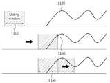
무선 전력을 이용한 통신 장치는 슬라이딩 윈도우(1110)를 이용하여 타겟 공진기에 인가되는 신호(1120)를 검출할 수 있다. 슬라이딩 윈도우(1110)에서 측정되는 신호의 세기에 기초하여 타겟 공진기에 저장되는 프레임이 검출(1130)될 수 있다. 프레임은 에너지 시퀀스의 형태를 정의될 수 있다. 무선 전력을 이용한 통신 장치는 슬라이딩 윈도우(1110)를 포함하는 특정 구간(1140)에서 인가되는 신호를 축적하고, 축적된 신호에서 포락선을 검출하며, 검출된 포락선의 기울기를 계산, 기울기가 최대 값을 가지는 경우의 지점을 상호 공진 시작점으로 추정할 수 있다.A communication device using wireless power can detect a
상술한 방법들은 다양한 컴퓨터 수단을 통하여 수행될 수 있는 프로그램 명령 형태로 구현되어 컴퓨터 판독 가능 매체에 기록될 수 있다. 상기 컴퓨터 판독 가능 매체는 프로그램 명령, 데이터 파일, 데이터 구조 등을 단독으로 또는 조합하여 포함할 수 있다. 상기 매체에 기록되는 프로그램 명령은 본 발명을 위하여 특별히 설계되고 구성된 것들이거나 컴퓨터 소프트웨어 당업자에게 공지되어 사용 가능한 것일 수도 있다.The above-described methods may be implemented in the form of program instructions that can be executed through various computer means and recorded in a computer-readable medium. The computer-readable medium may include program instructions, data files, data structures, and the like, alone or in combination. The program instructions recorded on the medium may be those specially designed and constructed for the present invention or may be available to those skilled in the art of computer software.
이상과 같이 본 발명은 비록 한정된 실시예와 도면에 의해 설명되었으나, 본 발명은 상기의 실시예에 한정되는 것은 아니며, 본 발명이 속하는 분야에서 통상의 지식을 가진 자라면 이러한 기재로부터 다양한 수정 및 변형이 가능하다.While the invention has been shown and described with reference to certain preferred embodiments thereof, it will be understood by those of ordinary skill in the art that various changes in form and details may be made therein without departing from the spirit and scope of the invention as defined by the appended claims. This is possible.
그러므로, 본 발명의 범위는 설명된 실시예에 국한되어 정해져서는 아니 되며, 후술하는 특허청구범위뿐 아니라 이 특허청구범위와 균등한 것들에 의해 정해져야 한다.Therefore, the scope of the present invention should not be limited to the described embodiments, but should be determined by the equivalents of the claims, as well as the claims.
Claims (21)
Translated fromKorean상기 포락선 상에서 최대 기울기에 대응하는 상기 일정한 간격을 갖는 2개의 지점 중에서 선행하는 지점을 상기 소스 공진기와 상기 타겟 공진기 간의 상호 공진 시작점으로 추정하는 추정부 를 포함하는 무선 전력을 이용한 통신 장치.A calculation unit for calculating a slope between two points having a constant interval on the envelope of the waveform of the energy stored in the target resonator through mutual resonance with the source resonator; And
And estimating means for estimating a preceding point out of two points having the predetermined interval corresponding to the maximum slope on the envelope as a mutual resonance starting point between the source resonator and the target resonator.
상기 타겟 공진기에 인가되는 전류 또는 전압의 파형에서 포락선을 검출하는 포락선 검출부
를 더 포함하는 무선 전력을 이용한 통신 장치.The method according to claim 1,
An envelope detector for detecting an envelope in a waveform of a current or voltage applied to the target resonator,
Wherein the wireless communication device further comprises:
상기 계산부는
상기 검출된 포락선의 각 지점에서 접선의 기울기를 계산하는
무선 전력을 이용한 통신 장치.3. The method of claim 2,
The calculation unit
The slope of the tangent line at each point of the detected envelope is calculated
A communication device using wireless power.
설정된 슬라이딩 윈도우 구간에서 상기 타겟 공진기에 인가되는 신호의 세기를 측정하여 상기 소스 공진기로부터 전송된 프레임을 검출하는 프레임 검출부
를 더 포함하는 무선 전력을 이용한 통신 장치.The method according to claim 1,
And a frame detector for measuring the intensity of a signal applied to the target resonator in a set sliding window period and detecting a frame transmitted from the source resonator,
Wherein the wireless communication device further comprises:
상기 프레임은
상기 소스 공진기로부터 전송된 프레임의 검출, 상기 소스 공진기와 상기 타겟 공진기 간의 상기 상호 공진 시작점 추정 및 상기 타겟 공진기에 저장된 에너지의 채득(capture) 포인트 검출에 사용되는 프리앰블 영역; 및
상기 소스 공진기로부터 상기 타겟 공진기로의 에너지 전송 및 데이터 전송에 사용되는 바디 영역
을 포함하는 무선 전력을 이용한 통신 장치.6. The method of claim 5,
The frame
A preamble region used for detecting a frame transmitted from the source resonator, estimating the mutual resonance starting point between the source resonator and the target resonator, and detecting a capture point of energy stored in the target resonator; And
A body region used for energy transmission and data transmission from the source resonator to the target resonator;
Wherein the wireless communication device is a wireless communication device.
상기 타겟 공진기와 상기 소스 공진기가 상호 공진을 시작하기 이전 상태인, 아이들 리슨(Idle listen) 상태에서는, 상기 소스 공진기가 에너지를 전송하면 상호 공진을 통하여 바로 에너지를 수신할 수 있도록, 상기 타겟 공진기를 활성화(activate) 된 상태로 유지시키는 제어부
를 더 포함하는 무선 전력을 이용한 통신 장치.The method according to claim 1,
In the idle listening state in which the target resonator and the source resonator start mutual resonance, when the source resonator transmits energy, the target resonator The control unit maintains the activated state
Wherein the wireless communication device further comprises:
상기 설정된 슬라이딩 윈도우 구간을 포함하는 특정 구간에서 상기 타겟 공진기에 인가되는 신호들을 축적하는 신호 축적부
를 더 포함하는 무선 전력을 이용한 통신 장치.6. The method of claim 5,
And a signal accumulation unit for accumulating signals applied to the target resonator in a specific section including the set sliding window period,
Wherein the wireless communication device further comprises:
상기 계산부는
상기 축적된 신호들에서 검출된 포락선의 기울기를 계산하는
를 더 포함하는 무선 전력을 이용한 통신 장치.9. The method of claim 8,
The calculation unit
And calculates the slope of the envelope detected in the accumulated signals
Wherein the wireless communication device further comprises:
상기 포락선 검출부는
상기 전류 또는 상기 전압을 입력으로 하여 포락선 검출용 아날로그 회로의 출력으로부터 상기 포락선을 획득하는
무선 전력을 이용한 통신 장치.3. The method of claim 2,
The envelope detector
And acquires the envelope from the output of the analog circuit for envelope detection with the current or the voltage as an input
A communication device using wireless power.
상기 포락선 검출부는
상기 전압 또는 상기 전류로부터 아날로그-디지털 변환(ADC) 샘플링 된 신호를 공진 주파수의 특정 신호 파형 중의 하나와 곱하여 하향 변환(down conversion)된 신호를 생성하는 하향 변환부;
상기 하향 변환된 신호를 이산 푸리에 변환 또는 고속 푸리에 변환하여 주파수 영역 신호로 변환하는 변환부;
상기 주파수 영역 신호에 저역 통과 필터링을 수행하여 하모닉 성분이 제거된 신호를 생성하는 필터링부; 및
상기 하모닉 성분이 제거된 신호를 이산 푸리에 역변환 또는 고속 푸리에 역변환하여 시간 영역 신호로 변환하는 역변환부
를 포함하는 무선 전력을 이용한 통신 장치.3. The method of claim 2,
The envelope detector
A down-conversion unit for multiplying an analog-to-digital (ADC) sampled signal from the voltage or the current by one of a specific signal waveform of a resonance frequency to generate a down-converted signal;
A converter for performing a discrete Fourier transform or a fast Fourier transform on the down-converted signal to convert the down-converted signal into a frequency domain signal;
A filtering unit for performing a low-pass filtering on the frequency-domain signal to generate a signal from which harmonic components are removed; And
An inverse transform unit for performing inverse Fourier inverse fast Fourier transform or inverse fast Fourier transform on the signal from which the harmonic component has been removed,
Wherein the communication device is a wireless communication device.
상기 포락선 검출부는
상기 전압 또는 상기 전류로부터 아날로그-디지털 변환(ADC) 샘플링 된 신호를 이산 푸리에 변환 또는 고속 푸리에 변환하여 주파수 영역 신호로 변환하는 변환부;
상기 주파수 영역 신호를 소정의 주파수만큼 순환 이동(circular shift)시키는 순환 이동부;
상기 순환 이동된 신호에 저역 통과 필터링을 수행하여 하모닉 성분이 제거된 신호를 생성하는 필터링부; 및
상기 하모닉 성분이 제거된 신호를 이산 푸리에 역변환 또는 고속 푸리에 역변환하여 시간 영역 신호로 변환하는 역변환부
를 포함하는 무선 전력을 이용한 통신 장치.3. The method of claim 2,
The envelope detector
A converter for performing a discrete Fourier transform or a fast Fourier transform on an analog-to-digital (ADC) sampled signal from the voltage or the current to convert the signal into a frequency domain signal;
A circulating unit for circularly shifting the frequency domain signal by a predetermined frequency;
A filtering unit for performing a low-pass filtering on the circulated signal to generate a signal from which harmonic components are removed; And
An inverse transform unit for performing inverse Fourier inverse fast Fourier transform or inverse fast Fourier transform on the signal from which the harmonic component has been removed,
Wherein the communication device is a wireless communication device.
상기 포락선 검출부는
상기 전압 또는 상기 전류로부터 아날로그-디지털 변환(ADC) 샘플링 된 신호를 공진 주파수의 특정 신호 파형 중의 하나와 곱하여 하향 변환(down conversion)된 신호를 생성하는 하향 변환부; 및
시간 영역에서 컨볼루션을 통해 상기 하향 변환된 신호에 저역 통과 필터링을 수행하여, 하모닉 성분이 제거된 신호를 생성하는 필터링부
를 포함하는 무선 전력을 이용한 통신 장치.3. The method of claim 2,
The envelope detector
A down-conversion unit for multiplying an analog-to-digital (ADC) sampled signal from the voltage or the current by one of a specific signal waveform of a resonance frequency to generate a down-converted signal; And
A low pass filtering unit for performing low pass filtering on the down-converted signal through convolution in a time domain to generate a signal from which harmonic components are removed,
Wherein the communication device is a wireless communication device.
상기 검출된 포락선의 크기가 피크(peak)인 피크 포인트를 검출하는 피크 포인트 검출부; 및
상기 검출된 피크 포인트에서 상기 타겟 공진기에 저장된 에너지를 채득(capture)하는 채득부
를 더 포함하는 무선 전력을 이용한 통신 장치.3. The method of claim 2,
A peak point detecting unit for detecting a peak point where a size of the detected envelope is a peak; And
A detector for capturing energy stored in the target resonator at the detected peak point;
Wherein the wireless communication device further comprises:
상기 상호 공진 시작점을 기준으로 하여 상기 타겟 공진기의 자기 공진을 활성화 시켜, 상기 소스 공진기로부터 전송된 에너지를 수신하는 수신부;
상기 수신한 에너지의 양에 기초하여 상기 소스 공진기가 전송하는 정보를 복조하는 복조부; 및
상기 상호 공진 시작점을 기준으로 하여, 상기 소스 공진기와의 상호 공진 여부에 따라 상기 소스 공진기로 전송하는 정보를 변조하는 변조부
를 더 포함하는 무선 전력을 이용한 통신 장치.The method according to claim 1,
A receiving unit for activating self resonance of the target resonator based on the mutual resonance starting point and receiving energy transmitted from the source resonator;
A demodulator for demodulating information transmitted by the source resonator based on the amount of the received energy; And
And a modulator for modulating information to be transmitted to the source resonator according to mutual resonance with the source resonator,
Wherein the wireless communication device further comprises:
상기 포락선 상에서 최대 기울기에 대응하는 상기 일정한 간격을 갖는 2개의 지점 중에서 선행하는 지점을 상기 소스 공진기와 상기 타겟 공진기 간의 상호 공진 시작점으로 추정하는 단계
를 포함하는 무선 전력을 이용한 통신 방법.Calculating a slope between two points having a constant interval on the envelope of the waveform of the energy stored in the target resonator through mutual resonance with the source resonator; And
Estimating a preceding point out of two points having the constant interval corresponding to a maximum slope on the envelope as a mutual resonance starting point between the source resonator and the target resonator
Wherein the wireless communication device is a wireless communication device.
상기 타겟 공진기에 인가되는 전류 또는 전압의 파형에서 포락선을 검출하는 단계
를 더 포함하는 무선 전력을 이용한 통신 방법.17. The method of claim 16,
Detecting an envelope in a waveform of a current or voltage applied to the target resonator
Further comprising the steps of:
상기 타겟 공진기와 상기 소스 공진기가 상호 공진을 시작하기 이전 상태인, 아이들 리슨(Idle listen) 상태에서는, 상기 소스 공진기가 에너지를 전송하면 상호 공진을 통하여 바로 에너지를 수신할 수 있도록, 상기 타겟 공진기를 활성화(activate) 된 상태로 유지시키는 단계
를 더 포함하는 무선 전력을 이용한 통신 방법.17. The method of claim 16,
In the idle listening state in which the target resonator and the source resonator start mutual resonance, when the source resonator transmits energy, the target resonator Keeping it in an activated state
Further comprising the steps of:
상기 검출된 포락선의 크기가 피크(peak)인 피크 포인트를 검출하는 단계; 및
상기 검출된 피크 포인트에서 상기 타겟 공진기에 저장된 에너지를 채득(capture)하는 단계
를 더 포함하는 무선 전력을 이용한 통신 방법.18. The method of claim 17,
Detecting a peak point where the size of the detected envelope is a peak; And
Capturing energy stored in the target resonator at the detected peak point
Further comprising the steps of:
상기 상호 공진을 통하여 상기 타겟 공진기에 저장된 에너지의 파형에서 포락선을 검출하는 포락선 검출부;
상기 검출된 포락선 상에서, 일정한 간격을 갖는 두 지점 간의 기울기를 계산하는 계산부; 및
상기 포락선 상에서 최대 기울기에 대응하는 상기 일정한 간격을 갖는 2개의 지점 중에서 선행하는 지점을 상기 소스 공진기와 상기 타겟 공진기 간의 상호 공진 시작점으로 추정하는 추정부
를 포함하는 무선 전력을 이용한 통신 시스템.A transmission unit for transmitting energy stored in the source resonator to the target resonator through mutual resonance;
An envelope detector for detecting an envelope in a waveform of energy stored in the target resonator through the mutual resonance;
A calculation unit for calculating a slope between two points having a predetermined interval on the detected envelope; And
And estimating a preceding point out of two points having the predetermined interval corresponding to the maximum slope on the envelope as a mutual resonance start point between the source resonator and the target resonator,
The communication system using wireless power.
Priority Applications (5)
| Application Number | Priority Date | Filing Date | Title |
|---|---|---|---|
| KR1020110097543AKR101920471B1 (en) | 2011-09-27 | 2011-09-27 | Communication system using wireless power |
| US13/433,478US9213932B2 (en) | 2011-09-27 | 2012-03-29 | Communication system using wireless power |
| EP12171191.5AEP2575083B1 (en) | 2011-09-27 | 2012-06-07 | Communication system using wireless power |
| JP2012213211AJP5976481B2 (en) | 2011-09-27 | 2012-09-26 | COMMUNICATION DEVICE AND METHOD USING WIRELESS POWER AND COMMUNICATION SYSTEM |
| CN201210365543.4ACN103023537B (en) | 2011-09-27 | 2012-09-27 | Use the communication system of wireless power |
Applications Claiming Priority (1)
| Application Number | Priority Date | Filing Date | Title |
|---|---|---|---|
| KR1020110097543AKR101920471B1 (en) | 2011-09-27 | 2011-09-27 | Communication system using wireless power |
Publications (2)
| Publication Number | Publication Date |
|---|---|
| KR20130033704A KR20130033704A (en) | 2013-04-04 |
| KR101920471B1true KR101920471B1 (en) | 2018-11-22 |
Family
ID=46229312
Family Applications (1)
| Application Number | Title | Priority Date | Filing Date |
|---|---|---|---|
| KR1020110097543AActiveKR101920471B1 (en) | 2011-09-27 | 2011-09-27 | Communication system using wireless power |
Country Status (5)
| Country | Link |
|---|---|
| US (1) | US9213932B2 (en) |
| EP (1) | EP2575083B1 (en) |
| JP (1) | JP5976481B2 (en) |
| KR (1) | KR101920471B1 (en) |
| CN (1) | CN103023537B (en) |
Families Citing this family (14)
| Publication number | Priority date | Publication date | Assignee | Title |
|---|---|---|---|---|
| KR101991341B1 (en)* | 2013-01-04 | 2019-06-20 | 삼성전자 주식회사 | Wireless power reception device and wireless power transmission system |
| KR102028112B1 (en)* | 2013-01-14 | 2019-10-04 | 삼성전자주식회사 | Apparatus for power and data transmission and data reception using mutual resonance, apparatus for power and data reception and data transmission using mutual resonance, method thereof |
| KR101529635B1 (en)* | 2013-05-10 | 2015-06-19 | 한국과학기술원 | Envelope detecting method using maximum voltage transfer matching technique from resonance antena to receiver and Receivers thereof |
| KR101949954B1 (en)* | 2013-06-07 | 2019-02-19 | 삼성전자주식회사 | Wireless power transmission apparatus for high efficient energy charging |
| KR101949127B1 (en) | 2013-08-01 | 2019-02-18 | 삼성전자주식회사 | Method and apparatus for wireless energy transmission with hybrid synchronization scheme |
| KR102155371B1 (en)* | 2013-09-09 | 2020-09-11 | 삼성전자주식회사 | Method and apparatus of wireless power transmission for cancelling harmonics noise |
| US20150200732A1 (en)* | 2014-01-10 | 2015-07-16 | Korea Advanced Institute Of Science And Technology | Transceivers using resonant coupling and nonlinear effect by plasma wave and receivers used in inter-chip or intra-chip communication |
| KR101661907B1 (en)* | 2014-01-10 | 2016-10-04 | 한국과학기술원 | Transceiver using resonant coupling and nonlinear effect by plasma wave |
| KR102134430B1 (en)* | 2014-05-21 | 2020-07-15 | 삼성전자주식회사 | Wireless power receiving device and method to receive power wirelessly based on switching |
| EP3346581B1 (en)* | 2017-01-04 | 2023-06-14 | LG Electronics Inc. | Wireless charger for mobile terminal in vehicle |
| KR102092445B1 (en)* | 2017-12-12 | 2020-03-23 | 한국과학기술원 | Powerless electromagnetic sensor and surgical navigation system comprising the same |
| US10812199B1 (en)* | 2019-08-28 | 2020-10-20 | Nxp B.V. | Quality-factor control for a near-field wireless device |
| CN112067944A (en)* | 2020-09-09 | 2020-12-11 | 国网江苏省电力有限公司盐城供电分公司 | Single-phase grounding fault detection control method for power transmission and distribution line |
| KR102492319B1 (en)* | 2021-07-08 | 2023-01-26 | 고려대학교 산학협력단 | Back data transmission circuit and method that is robust to load changes |
Citations (2)
| Publication number | Priority date | Publication date | Assignee | Title |
|---|---|---|---|---|
| US20050129141A1 (en) | 2003-10-31 | 2005-06-16 | Seung-Hwan Lee | Apparatus and method for compensating for analog quadrature modulation error |
| US20100189196A1 (en)* | 2009-01-23 | 2010-07-29 | Semiconductor Manufacturing International (Shanghai) Corporation | Amplitude shift keyed (ask) demodulation pattern and use in radio frequency identification (rfid) |
Family Cites Families (16)
| Publication number | Priority date | Publication date | Assignee | Title |
|---|---|---|---|---|
| AT395224B (en) | 1990-08-23 | 1992-10-27 | Mikron Ges Fuer Integrierte Mi | CONTACTLESS, INDUCTIVE DATA TRANSFER SYSTEM |
| JPH09321652A (en)* | 1996-05-27 | 1997-12-12 | Denso Corp | Radio communication equipment |
| ATE279047T1 (en) | 2000-04-18 | 2004-10-15 | Schleifring Und Appbau Gmbh | ARRANGEMENT FOR THE CONTACTLESS TRANSMISSION OF ELECTRICAL SIGNALS OR ENERGY |
| JP2006006880A (en)* | 2004-06-28 | 2006-01-12 | Nobuyasu Watanabe | Golf exercising mechanism |
| US7579906B2 (en)* | 2004-11-12 | 2009-08-25 | National Semiconductor Corporation | System and method for providing a low power low voltage data detection circuit for RF AM signals in EPC0 compliant RFID tags |
| US7825543B2 (en) | 2005-07-12 | 2010-11-02 | Massachusetts Institute Of Technology | Wireless energy transfer |
| JP2007124628A (en)* | 2005-09-29 | 2007-05-17 | Univ Of Tokyo | Switched antenna, pulse generator and related apparatus |
| JP2008066880A (en)* | 2006-09-05 | 2008-03-21 | Matsushita Electric Ind Co Ltd | Pulse receiving apparatus and synchronization timing estimation method |
| JP5024002B2 (en)* | 2007-12-03 | 2012-09-12 | パナソニック株式会社 | Antenna device |
| CN101790815A (en)* | 2007-12-10 | 2010-07-28 | 欧姆龙株式会社 | Rfid tag, and system and method for detecting change of rfid tag environment |
| CN101227209B (en)* | 2008-01-25 | 2011-07-13 | 宇龙计算机通信科技(深圳)有限公司 | Method and theftproof system of mobile terminal based on blue tooth submachine |
| US20090284369A1 (en) | 2008-05-13 | 2009-11-19 | Qualcomm Incorporated | Transmit power control for a wireless charging system |
| US8452235B2 (en) | 2009-03-28 | 2013-05-28 | Qualcomm, Incorporated | Tracking receiver devices with wireless power systems, apparatuses, and methods |
| JP5365306B2 (en) | 2009-03-31 | 2013-12-11 | 富士通株式会社 | Wireless power supply system |
| JP2010284065A (en) | 2009-06-08 | 2010-12-16 | Nec Tokin Corp | Power/signal transmission module, noncontact charging module, and noncontact charging and signal transmission systems |
| JP5434330B2 (en) | 2009-07-22 | 2014-03-05 | ソニー株式会社 | Power receiving device, power transmission system, charging device, and power transmission method |
- 2011
- 2011-09-27KRKR1020110097543Apatent/KR101920471B1/enactiveActive
- 2012
- 2012-03-29USUS13/433,478patent/US9213932B2/enactiveActive
- 2012-06-07EPEP12171191.5Apatent/EP2575083B1/enactiveActive
- 2012-09-26JPJP2012213211Apatent/JP5976481B2/enactiveActive
- 2012-09-27CNCN201210365543.4Apatent/CN103023537B/enactiveActive
Patent Citations (2)
| Publication number | Priority date | Publication date | Assignee | Title |
|---|---|---|---|---|
| US20050129141A1 (en) | 2003-10-31 | 2005-06-16 | Seung-Hwan Lee | Apparatus and method for compensating for analog quadrature modulation error |
| US20100189196A1 (en)* | 2009-01-23 | 2010-07-29 | Semiconductor Manufacturing International (Shanghai) Corporation | Amplitude shift keyed (ask) demodulation pattern and use in radio frequency identification (rfid) |
Also Published As
| Publication number | Publication date |
|---|---|
| EP2575083A1 (en) | 2013-04-03 |
| JP5976481B2 (en) | 2016-08-23 |
| EP2575083B1 (en) | 2017-10-11 |
| JP2013074794A (en) | 2013-04-22 |
| KR20130033704A (en) | 2013-04-04 |
| US9213932B2 (en) | 2015-12-15 |
| CN103023537A (en) | 2013-04-03 |
| US20130080091A1 (en) | 2013-03-28 |
| CN103023537B (en) | 2016-04-20 |
Similar Documents
| Publication | Publication Date | Title |
|---|---|---|
| KR101920471B1 (en) | Communication system using wireless power | |
| KR101987283B1 (en) | Communication system using wireless power | |
| KR101844427B1 (en) | Communication system using wireless power | |
| JP4572949B2 (en) | Wireless communication apparatus, wireless communication system, wireless communication method, and program | |
| KR101779829B1 (en) | Apparatus and method for envelope detection | |
| CN104756359B (en) | Wireless energy transmission method, device and system | |
| CN110350676B (en) | Wireless charging communication method and device | |
| US9461713B2 (en) | Data reception apparatus and method, data transmission apparatus, and data communication system using mutual resonance | |
| KR101890705B1 (en) | Signal process apparatus and signal process method | |
| KR101949797B1 (en) | Communication system using wireless power | |
| KR20150045755A (en) | Method and apparatus for impedance matching using resonator isolation in wireless power transmission system | |
| KR101839382B1 (en) | Communication system using wireless power | |
| JP3189731U (en) | Wireless transmission device | |
| US20150105034A1 (en) | Wireless transmission device |
Legal Events
| Date | Code | Title | Description |
|---|---|---|---|
| PA0109 | Patent application | Patent event code:PA01091R01D Comment text:Patent Application Patent event date:20110927 | |
| PG1501 | Laying open of application | ||
| A201 | Request for examination | ||
| PA0201 | Request for examination | Patent event code:PA02012R01D Patent event date:20160901 Comment text:Request for Examination of Application Patent event code:PA02011R01I Patent event date:20110927 Comment text:Patent Application | |
| E902 | Notification of reason for refusal | ||
| PE0902 | Notice of grounds for rejection | Comment text:Notification of reason for refusal Patent event date:20180219 Patent event code:PE09021S01D | |
| E701 | Decision to grant or registration of patent right | ||
| PE0701 | Decision of registration | Patent event code:PE07011S01D Comment text:Decision to Grant Registration Patent event date:20180822 | |
| GRNT | Written decision to grant | ||
| PR0701 | Registration of establishment | Comment text:Registration of Establishment Patent event date:20181114 Patent event code:PR07011E01D | |
| PR1002 | Payment of registration fee | Payment date:20181115 End annual number:3 Start annual number:1 | |
| PG1601 | Publication of registration | ||
| PR1001 | Payment of annual fee | Payment date:20221020 Start annual number:5 End annual number:5 | |
| PR1001 | Payment of annual fee | Payment date:20231017 Start annual number:6 End annual number:6 |