KR101920236B1 - Method for charging battery and an electronic device thereof - Google Patents
Method for charging battery and an electronic device thereofDownload PDFInfo
- Publication number
- KR101920236B1 KR101920236B1KR1020120065421AKR20120065421AKR101920236B1KR 101920236 B1KR101920236 B1KR 101920236B1KR 1020120065421 AKR1020120065421 AKR 1020120065421AKR 20120065421 AKR20120065421 AKR 20120065421AKR 101920236 B1KR101920236 B1KR 101920236B1
- Authority
- KR
- South Korea
- Prior art keywords
- charging
- electronic device
- battery
- charging circuit
- wired
- Prior art date
- Legal status (The legal status is an assumption and is not a legal conclusion. Google has not performed a legal analysis and makes no representation as to the accuracy of the status listed.)
- Active
Links
Images


Classifications
- G—PHYSICS
- G06—COMPUTING OR CALCULATING; COUNTING
- G06F—ELECTRIC DIGITAL DATA PROCESSING
- G06F1/00—Details not covered by groups G06F3/00 - G06F13/00 and G06F21/00
- G06F1/26—Power supply means, e.g. regulation thereof
- G06F1/263—Arrangements for using multiple switchable power supplies, e.g. battery and AC
- H—ELECTRICITY
- H02—GENERATION; CONVERSION OR DISTRIBUTION OF ELECTRIC POWER
- H02J—CIRCUIT ARRANGEMENTS OR SYSTEMS FOR SUPPLYING OR DISTRIBUTING ELECTRIC POWER; SYSTEMS FOR STORING ELECTRIC ENERGY
- H02J7/00—Circuit arrangements for charging or depolarising batteries or for supplying loads from batteries
- H02J7/0068—Battery or charger load switching, e.g. concurrent charging and load supply
- G—PHYSICS
- G06—COMPUTING OR CALCULATING; COUNTING
- G06F—ELECTRIC DIGITAL DATA PROCESSING
- G06F1/00—Details not covered by groups G06F3/00 - G06F13/00 and G06F21/00
- G06F1/26—Power supply means, e.g. regulation thereof
- G06F1/266—Arrangements to supply power to external peripherals either directly from the computer or under computer control, e.g. supply of power through the communication port, computer controlled power-strips
- H—ELECTRICITY
- H02—GENERATION; CONVERSION OR DISTRIBUTION OF ELECTRIC POWER
- H02J—CIRCUIT ARRANGEMENTS OR SYSTEMS FOR SUPPLYING OR DISTRIBUTING ELECTRIC POWER; SYSTEMS FOR STORING ELECTRIC ENERGY
- H02J50/00—Circuit arrangements or systems for wireless supply or distribution of electric power
- H—ELECTRICITY
- H02—GENERATION; CONVERSION OR DISTRIBUTION OF ELECTRIC POWER
- H02J—CIRCUIT ARRANGEMENTS OR SYSTEMS FOR SUPPLYING OR DISTRIBUTING ELECTRIC POWER; SYSTEMS FOR STORING ELECTRIC ENERGY
- H02J50/00—Circuit arrangements or systems for wireless supply or distribution of electric power
- H02J50/40—Circuit arrangements or systems for wireless supply or distribution of electric power using two or more transmitting or receiving devices
- H—ELECTRICITY
- H02—GENERATION; CONVERSION OR DISTRIBUTION OF ELECTRIC POWER
- H02J—CIRCUIT ARRANGEMENTS OR SYSTEMS FOR SUPPLYING OR DISTRIBUTING ELECTRIC POWER; SYSTEMS FOR STORING ELECTRIC ENERGY
- H02J7/00—Circuit arrangements for charging or depolarising batteries or for supplying loads from batteries
- H02J7/02—Circuit arrangements for charging or depolarising batteries or for supplying loads from batteries for charging batteries from AC mains by converters
- H—ELECTRICITY
- H02—GENERATION; CONVERSION OR DISTRIBUTION OF ELECTRIC POWER
- H02J—CIRCUIT ARRANGEMENTS OR SYSTEMS FOR SUPPLYING OR DISTRIBUTING ELECTRIC POWER; SYSTEMS FOR STORING ELECTRIC ENERGY
- H02J7/00—Circuit arrangements for charging or depolarising batteries or for supplying loads from batteries
- H02J7/34—Parallel operation in networks using both storage and other DC sources, e.g. providing buffering
- H—ELECTRICITY
- H02—GENERATION; CONVERSION OR DISTRIBUTION OF ELECTRIC POWER
- H02J—CIRCUIT ARRANGEMENTS OR SYSTEMS FOR SUPPLYING OR DISTRIBUTING ELECTRIC POWER; SYSTEMS FOR STORING ELECTRIC ENERGY
- H02J2207/00—Indexing scheme relating to details of circuit arrangements for charging or depolarising batteries or for supplying loads from batteries
- H02J2207/40—Indexing scheme relating to details of circuit arrangements for charging or depolarising batteries or for supplying loads from batteries adapted for charging from various sources, e.g. AC, DC or multivoltage
- H—ELECTRICITY
- H02—GENERATION; CONVERSION OR DISTRIBUTION OF ELECTRIC POWER
- H02J—CIRCUIT ARRANGEMENTS OR SYSTEMS FOR SUPPLYING OR DISTRIBUTING ELECTRIC POWER; SYSTEMS FOR STORING ELECTRIC ENERGY
- H02J7/00—Circuit arrangements for charging or depolarising batteries or for supplying loads from batteries
- H02J7/00032—Circuit arrangements for charging or depolarising batteries or for supplying loads from batteries characterised by data exchange
- H02J7/00038—Circuit arrangements for charging or depolarising batteries or for supplying loads from batteries characterised by data exchange using passive battery identification means, e.g. resistors or capacitors
- H—ELECTRICITY
- H02—GENERATION; CONVERSION OR DISTRIBUTION OF ELECTRIC POWER
- H02J—CIRCUIT ARRANGEMENTS OR SYSTEMS FOR SUPPLYING OR DISTRIBUTING ELECTRIC POWER; SYSTEMS FOR STORING ELECTRIC ENERGY
- H02J7/00—Circuit arrangements for charging or depolarising batteries or for supplying loads from batteries
- H02J7/00032—Circuit arrangements for charging or depolarising batteries or for supplying loads from batteries characterised by data exchange
- H02J7/00045—Authentication, i.e. circuits for checking compatibility between one component, e.g. a battery or a battery charger, and another component, e.g. a power source
- Y—GENERAL TAGGING OF NEW TECHNOLOGICAL DEVELOPMENTS; GENERAL TAGGING OF CROSS-SECTIONAL TECHNOLOGIES SPANNING OVER SEVERAL SECTIONS OF THE IPC; TECHNICAL SUBJECTS COVERED BY FORMER USPC CROSS-REFERENCE ART COLLECTIONS [XRACs] AND DIGESTS
- Y02—TECHNOLOGIES OR APPLICATIONS FOR MITIGATION OR ADAPTATION AGAINST CLIMATE CHANGE
- Y02E—REDUCTION OF GREENHOUSE GAS [GHG] EMISSIONS, RELATED TO ENERGY GENERATION, TRANSMISSION OR DISTRIBUTION
- Y02E60/00—Enabling technologies; Technologies with a potential or indirect contribution to GHG emissions mitigation
- Y02E60/10—Energy storage using batteries
Landscapes
- Engineering & Computer Science (AREA)
- Theoretical Computer Science (AREA)
- Power Engineering (AREA)
- General Engineering & Computer Science (AREA)
- Physics & Mathematics (AREA)
- General Physics & Mathematics (AREA)
- Computer Networks & Wireless Communication (AREA)
- Computer Hardware Design (AREA)
- Charge And Discharge Circuits For Batteries Or The Like (AREA)
- Secondary Cells (AREA)
Abstract
Translated fromKoreanDescription
Translated fromKorean본 발명은 배터리를 충전하기 위한 방법 및 그 전자 장치에 관한 것이다.
The present invention relates to a method for charging a battery and its electronic device.
휴대 가능한 각종 전자 장치에 대한 사용량이 증가하면서, 전자 장치의 성능 및 사용 시간에 영향을 미치는 고성능 배터리 및 배터리 충전 방식에 대한 관심이 증가하고 있다. 이에 따라, 최근 들어 유선 충전뿐만 아니라, 무선 충전이 가능한 전자 장치가 제공되고 있다. 최근 제공되는 전자 장치는 하나의 충전회로를 구비함으로써, 전자 장치에 유선 충전 장치가 연결된 경우에는 유선 충전 장치로부터의 전원 공급 경로와 충전회로를 연결하여 배터리를 충전하고, 전자 장치에 무선 충전 장치가 연결된 경우에는 무선 충전 장치로부터의 전원 공급 경로와 충전회로를 연결하여 배터리를 충전한다.With increasing usage for portable electronic devices, there is an increasing interest in high performance batteries and battery charging schemes that affect the performance and usage time of electronic devices. Accordingly, in recent years, an electronic device capable of wireless charging as well as wired charging has been provided. A recently provided electronic device includes one charging circuit, so that when the wired charging device is connected to the electronic device, the power supply path from the wired charging device and the charging circuit are connected to charge the battery, and the electronic charging device When connected, the charging circuit is connected to the power supply path from the wireless charging device to charge the battery.
한편, 전자 장치에서는 USB OTG(USB On-The-Go) 기능을 제공하고 있다. USB OTG 기능은 주 컴퓨터의 간섭 없이, 개인 휴대 정보 단말기(PDA), MP3 및 휴대폰, 마우스, 키보드 및 메모리 등과 같은 전자 장치들 간에 USB로 통신하여 동작할 수 있는 기능을 의미한다. 예를 들어, 휴대폰에 USB로 메모리를 연결하여 데이터를 이동시키는 기능을 USB OTG라 한다.On the other hand, electronic devices provide a USB On-The-Go (USB OTG) function. The USB OTG function refers to the ability to communicate and operate via USB between electronic devices such as personal digital assistants (PDAs), MP3s, and cell phones, mice, keyboards, and memories without interference from the main computer. For example, USB OTG is a function to move data by connecting memory to a mobile phone via USB.
일반적으로, 전자 장치들 간에 USB로 통신하는 USB OTG 동작 시, 서버로 동작하는 전자 장치는 클라이언트로 동작하는 전자 장치의 동작을 위한 전원을 공급해야 한다. 따라서, 서버로 동작하는 전자 장치는 USB OTG 동작 중에 배터리 잔량이 점차 감소하게 되며, 계속적인 USB OTG 동작을 위해서 배터리의 충전이 필요한 상황에 직면할 수 있다. 그러나, 전자 장치는 배터리를 충전하는 경로의 역 경로 즉, 충전회로를 포함하는 경로를 이용하여, 클라이언트 전자 장치로 USB OTG를 위한 전원을 공급하기 때문에, USB OTG 동작 중에 배터리를 충전하는 것이 불가능한 실정이다.Generally, in a USB OTG operation in which a USB is communicated between electronic devices, an electronic device acting as a server must supply power for operation of an electronic device operating as a client. Therefore, an electronic device operating as a server may gradually decrease the remaining battery power during USB OTG operation, and may face a situation in which charging of the battery is required for continuous USB OTG operation. However, since the electronic device supplies power for the USB OTG to the client electronic device using the reverse path of the path for charging the battery, that is, the path including the charging circuit, it is not possible to charge the battery during the USB OTG operation to be.
또한, 종래의 전자 장치는 공지된 다양한 충전회로들 중에서 사업자 및 개발자가 선택한 하나의 충전회로만을 구비고 있다. 즉, 종래의 전자 장치는 사업자 및 개발자가 선택한 하나의 충전회로만을 포함하기 때문에, 충전 시 상황에 따라 효율적으로 대처할 수 없는 실정이다.
In addition, conventional electronic devices are provided with only one charging circuit selected by the operator and the developer among the various known charging circuits. That is, since the conventional electronic device includes only one charging circuit selected by the provider and the developer, it can not efficiently cope with charging situations.
따라서, 본 발명의 실시 예는 전자 장치에서 배터리를 충전하기 위한 방법 및 장치를 제공함에 있다.Accordingly, an embodiment of the present invention is to provide a method and apparatus for charging a battery in an electronic device.
본 발명의 다른 실시 예는 전자 장치에서 적어도 두 개의 충전회로를 구비하여, USB OTG 동작 중에 배터리를 충전하는 방법 및 장치를 제공함에 있다.Another embodiment of the present invention is to provide a method and apparatus for charging a battery during USB OTG operation with at least two charging circuits in the electronic device.
본 발명의 또 다른 실시 예는 전자 장치에서 적어도 두 개의 충전회로를 구비하고, 외부 충전 장치의 타입 및 충전 용량에 따라 충전회로를 선택하는 방법 및 장치를 제공함에 있다.Yet another embodiment of the present invention is to provide a method and apparatus for selecting a charging circuit according to the type and charging capacity of an external charging apparatus, which has at least two charging circuits in an electronic apparatus.
본 발명의 또 다른 실시 예는 전자 장치에서 서로 다른 입력을 제공받는 적어도 두 개의 충전회로를 구비하여, 유선 충전 및 유선 충전을 동시에 수행하는 방법 및 장치를 제공함에 있다.
Another embodiment of the present invention is to provide a method and apparatus for simultaneously performing wired and wired charging with at least two charging circuits that are provided with different inputs in an electronic device.
본 발명의 실시 예에 따르면, 전자 장치의 배터리 충전 방법은, 외부 장치가 유선으로 연결된 경우, 제 1 충전회로를 이용하여 배터리의 전원을 상기 외부 장치로 공급하는 과정과, 상기 외부 장치로 전원을 공급하면서, 무선 충전 장치로부터 전원을 공급받는 과정과, 제 2 충전 회로를 이용하여 상기 무선 충전 장치로부터 공급되는 전원으로 상기 배터리를 충전하는 과정을 포함하는 것을 특징으로 한다.According to an embodiment of the present invention, a method of charging a battery of an electronic device includes the steps of supplying power of a battery to the external device using a first charging circuit when the external device is connected by wire, And charging the battery with power supplied from the wireless charging device by using the second charging circuit.
본 발명의 실시 예에 따르면, 배터리 충전 전자 장치는, 배터리와, 외부 장치가 유선으로 연결된 경우, 상기 배터리의 전원을 상기 외부 장치로 공급하는 제 1 충전회로와, 상기 제 1 충전회로가 상기 외부 장치로 전원을 공급하는 중에, 무선 충전 장치로부터 전원을 공급받고, 상기 무선 충전 장치로부터 공급되는 전원으로 상기 배터리를 충전하는 제 2 충전 회로를 포함하는 것을 특징으로 한다.According to an embodiment of the present invention, a battery charging electronic device includes a battery, a first charging circuit that supplies power of the battery to the external device when the external device is connected by wire, And a second charging circuit that receives power from the wireless charging device while charging power to the device and charges the battery with power supplied from the wireless charging device.
본 발명의 실시 예에 따르면, 전자 장치의 배터리 충전 방법은, 충전 장치가 연결된 경우, 복수의 충전회로 중에서 연결된 충전 장치에 대응하는 충전회로를 선택하는 과정과, 선택된 충전회로를 이용하여 충전 장치로부터의 전원으로 배터리를 충전하는 과정을 포함하는 것을 특징으로 한다.According to an embodiment of the present invention, a method of charging a battery of an electronic device includes the steps of: selecting a charging circuit corresponding to a connected charging device from among a plurality of charging circuits when the charging device is connected; And charging the battery with a power source of the battery.
본 발명의 실시 예에 따르면, 배터리 충전 전자 장치는, 배터리와, 상기 배터리를 충전하는 복수의 충전회로와, 충전 장치가 연결된 경우, 상기 복수의 충전회로 중에서 상기 연결된 충전 장치에 대응하는 충전회로를 선택하는 프로세서를 포함하며, 상기 복수의 충전회로 중에서 상기 선택된 충전회로는, 상기 충전 장치로부터의 전원으로 상기 배터리를 충전하는 것을 특징으로 한다.
According to an embodiment of the present invention, a battery charging electronic device includes a battery, a plurality of charging circuits for charging the battery, and a charging circuit corresponding to the connected charging device among the plurality of charging circuits when the charging device is connected And the selected charging circuit among the plurality of charging circuits charges the battery with power from the charging device.
본 발명의 전자 장치에서는 서로 다른 입력을 제공받는 적어도 두 개의 충전회로를 구비하여, USB OTG 동작 중에 배터리를 무선으로 충전할 수 있으며, 이에 따라 사용자 편의 및 배터리 사용 시간을 증가시킬 수 있는 효과가 있다. 또한, 종래 충전 시스템과 달리 외부 장치로부터 공급되는 전원을 충전회로로 전달하기 위한 스위치를 구비하지 않으므로, 설계 면적 및 설계 비용을 감소시킬 수 있는 효과가 있다. 또한, 본 발명의 전자 장치에서는 적어도 두 개의 충전회로를 구비하여, 외부 충전 장치의 타입 및 충전 용량에 따라 하나의 충전회로를 선택하고, 선택된 충전회로를 이용하여 배터리를 충전함으로써, 상황에 따라 효과적인 충전 방식을 선택하여 충전 효율을 향상시킬 수 있는 효과가 있다.
The electronic device of the present invention has at least two charging circuits that are provided with different inputs, so that the battery can be charged wirelessly during the USB OTG operation, thereby improving convenience for users and battery usage time . In addition, unlike the conventional charging system, there is no switch for transmitting the power supplied from the external device to the charging circuit, thereby reducing the design area and the design cost. The electronic device of the present invention may include at least two charging circuits to select one charging circuit according to the type of the external charging device and the charging capacity and to charge the battery using the selected charging circuit, There is an effect that the charging efficiency can be improved by selecting the charging mode.
도 1은 본 발명에 따른 전자 장치의 블록 구성을 도시하는 도면,
도 2는 본 발명에 따른 전자 장치에서 충전부의 상세한 블록 구성을 도시하는 도면,
도 3은 본 발명의 실시 예에 따른 전자 장치에서 OTG 및 충전 절차를 도시하는 도면,
도 4는 본 발명의 실시 예에 따른 전자 장치에서 유선 충전 절차를 도시하는 도면,
도 5a는 본 발명에 따른 전자 장치에서 OTG 동작을 수행하면서 무선 충전을 수행하는 절차를 도시하는 도면,
도 5b는 본 발명에 따른 전자 장치에서 OTG 동작을 수행하면서 무선 충전을 수행하는 절차에 대한 수단을 도시하는 도면,
도 6a는 본 발명에 따른 전자 장치에서 유선 충전 절차를 도시하는 도면, 및
도 6b는 본 발명에 따른 전자 장치에서 유선 충전 절차를 수행하기 위한 수단을 도시하는 도면.1 is a block diagram showing the configuration of an electronic device according to the present invention;
2 is a diagram showing a detailed block configuration of a charging unit in an electronic device according to the present invention,
3 is a diagram illustrating OTG and charging procedures in an electronic device according to an embodiment of the present invention;
4 is a diagram illustrating a wired charging procedure in an electronic device according to an embodiment of the present invention;
5A is a flowchart illustrating a procedure for performing wireless charging while performing an OTG operation in an electronic device according to the present invention.
Figure 5B illustrates the means for a procedure for performing wireless charging while performing an OTG operation in an electronic device according to the present invention;
6A is a diagram showing a wired charging procedure in an electronic device according to the present invention, and Fig.
Figure 6b illustrates means for performing a wired charging procedure in an electronic device according to the present invention;
이하 본 발명의 바람직한 실시 예를 첨부된 도면을 참조하여 설명한다. 그리고, 본 발명을 설명함에 있어서, 관련된 공지기능 혹은 구성에 대한 구체적인 설명이 본 발명의 요지를 불필요하게 흐릴 수 있다고 판단된 경우 그 상세한 설명은 생략할 것이다. 또한, 후술되는 용어들은 본 발명에서의 기능을 고려하여 정의된 용어들로서 이는 사용자, 운용자의 의도 또는 관례 등에 따라 달라질 수 있다. 그러므로 그 정의는 본 명세서 전반에 걸친 내용을 토대로 내려져야 할 것이다.
Hereinafter, preferred embodiments of the present invention will be described with reference to the accompanying drawings. In the following description of the present invention, a detailed description of known functions and configurations incorporated herein will be omitted when it may make the subject matter of the present invention rather unclear. In addition, the terms described below are defined in consideration of the functions of the present invention, which may vary depending on the intention of the user, the operator, or the custom. Therefore, the definition should be based on the contents throughout this specification.
이하 본 발명은 전자 장치에서 서로 다른 입력을 제공받는 적어도 두 개의 충전회로를 구비하여, USB OTG(USB On-The-Go) 및 충전 동작을 수행하는 방법 및 기술에 관해 설명할 것이다. 이하 설명에서 전자 장치는 이동통신 단말기, 스마트폰(Smart Phone), 태블릿 PC(Tablet Personal Computer), 디지털 카메라, MP3, 랩탑(Laptop), 넷북(Netbook), 및 휴대용 게임기와 같은 배터리(Battery) 충전이 가능한 각종 전자 장치를 모두 포함하는 의미이다.The present invention will now be described with respect to a method and a technique for carrying out a USB On-The-Go (USB OTG) and charging operation with at least two charging circuits that are provided with different inputs in an electronic device. In the following description, an electronic device may be used to charge a battery such as a mobile communication terminal, a smart phone, a tablet PC, a digital camera, MP3, a laptop, a netbook, It is meant to include all possible electronic devices.
이하 본 발명에서는 설명의 편의를 위해 전자 장치에서 두 개의 충전회로를 구비하는 경우를 예로 들어 설명할 것이다. 그러나, 이하 본 발명은 전자 장치에서 둘 이상의 충전회로를 구비하는 경우에도 동일한 방식으로 적용될 수 있다.
Hereinafter, the present invention will be described by taking as an example the case where two charging circuits are provided in an electronic device for convenience of explanation. However, the present invention can be applied in the same manner even when the electronic device includes two or more charging circuits.
도 1은 본 발명에 따른 전자 장치의 블록 구성을 도시하고 있다.Fig. 1 shows a block configuration of an electronic device according to the present invention.
상기 도 1을 참조하면, 전자 장치는 프로세서(100), 메모리(110), 충전부(120), 외부 장치 인터페이스(130) 및 터치스크린(140)을 포함하여 구성된다.Referring to FIG. 1, an electronic device includes a
프로세서(100)는 하나 이상의 프로세서로 구성될 수 있다. 프로세서(100)는 여러 가지의 소프트웨어 프로그램을 실행하여 전자 장치의 전반적인 동작을 제어 및 처리한다. 프로세서(100)는 메모리(110)에 저장된 소프트웨어 프로그램을 실행하여, 실행된 소프트웨어 프로그램에 대응하는 기능을 수행한다. 여기서, 후술되는 프로세서(100)의 동작은 별도로 구성된 적어도 하나의 하드웨어 및/혹은 소프트웨어에 의해 실행될 수도 있다. 예를 들어, 후술되는 프로세서(100)의 동작들은 충전부(120)에 집적된 하드웨어에서 직접 실행될 수도 있다.The
본 발명에 따른 프로세서(100)는 메모리(110)에 저장된 OTG 제어 프로그램(113)을 실행하여, USB OTG모드로 동작한다. 즉, 프로세서(100)는 외부 장치 인터페이스(130)를 통해 연결된 유선 연결 장치와 통신하면서, 전원을 공급하기 위한 기능을 제어한다. 여기서, 유선 연결 장치는, 전자 장치와 USB를 통해 연결되어 신호 송수신이 가능한 외부 전자 장치로서, 예를 들어, 휴대폰, 키보드, 마우스 혹은 메모리일 수 있다.The
또한, 프로세서(100)는 충전 제어 프로그램(114)을 실행하여, 충전부(120)가 외부 장치 인터페이스(130)를 통해 연결된 유선 충전 장치 및/혹은 무선 충전 장치로부터 전원을 공급받아 배터리를 충전할 수 있도록 하기 위한 기능을 제어한다. 이때, 프로세서(100)가 외부 장치 인터페이스(130)로부터 유선 충전 장치로부터 공급되는 전원 및 무선 충전 장치로부터 공급되는 전원이 충전부(120)에 서로 다른 입력 단자를 통해 제공되도록 제어함으로써, 충전부(120)는 유선 충전 및 무선 충전을 동시에 수행할 수 있도록 한다. 여기서, 유선 충전 장치는 전자 장치와 USB를 통해 연결되어 충전용 전원을 공급하는 TA(Travel Adaptor) 혹은 USB 충전기일 수 있으며, 무선 충전 장치는 외부 장치 인터페이스(130)를 통해 무선으로 연결된 외부 장치일 수 있다.The
또한, 프로세서(100)는 전자 장치가 USB OTG 모드로 동작하는 중에 무선 충전 이벤트가 발생될 시, 충전부(120)가 외부 장치 인터페이스(130)로부터 공급되는 무선 충전용 전원을 이용하여 배터리를 충전하도록 하기 위한 기능을 제어한다.In addition, when the wireless charging event is generated while the electronic device is operating in the USB OTG mode, the
또한, 프로세서(100)는 외부 장치 인터페이스(130)에 유선 충전 장치의 연결이 감지될 시, 연결된 유선 충전 장치의 ID, 타입 및/혹은 충전 용량을 감지하고, 충전부(120)에 구비된 두 개의 충전회로 중에서 유선 충전 장치의 ID, 타입 및/혹은 충전 용량에 대응하는 충전회로를 선택하여, 충전부(120)가 선택된 충전회로를 통해 배터리를 충전하도록 하기 위한 기능을 제어한다. 여기서, 프로세서(100)는 충전 장치의 ID를 통해 충전 장치의 타입 정보를 획득할 수도 있다.The
메모리(110)는 전자 장치의 전반적인 동작을 위한 명령어들을 포함하는 각종 프로그램 및 데이터를 저장한다. 메모리(110)는 자기 디스크 저장 장치와 같은 고속 랜덤 액세스 메모리 및/또는 비휘발성 메모리, 하나 이상의 광 저장 장치 및/또는 플래시 메모리(예: NAND, NOR) 중 적어도 하나를 포함하여 구성될 수 있다.
메모리(110)에 저장된 각종 프로그램은 표시 제어 프로그램(111), 터치 처리 프로그램(112), OTG 제어 프로그램(113) 및 충전 제어 프로그램(114)을 포함할 수 있다. 또한, 도시하지는 않았으나, 메모리(110)는 충전 장치의 타입 및/혹은 충전 용량에 대응하는 충전회로 선택 정보를 저장할 수 있다.Various programs stored in the
표시 제어 프로그램(111)은 전자 장치의 동작 중에 발생되는 각종 정보를 터치스크린(140)의 표시부(141)에 디스플레이하기 위한 명령어를 포함한다. 예를 들어, 표시 제어 프로그램(111)은 전자 장치가 유선 충전 및/혹은 무선 충전 중임을 나타내는 정보를 표시부(141)에 디스플레이하기 위한 명령어, 전자 장치가 USB OTG 동작 중이면서, 동시에 무선 충전 중임을 나타내는 정보를 표시부(141)에 디스플레이하기 위한 명령어를 포함할 수 있다.The
터치 처리 프로그램(112)은 전자 장치의 동작 중에 터치스크린(140)의 입력부(142)를 통해 발생되는 사용자 입력을 감지하기 위한 명령어를 포함한다. 예를 들어, 터치 처리 프로그램(112)은 USB OTG 모드로 동작을 요청하는 사용자 입력을 감지하기 위한 명령어를 포함할 수 있다.The
OTG 제어 프로그램(113)은 외부 장치 인터페이스(130)를 통해 유선 연결 장치가 감지될 시, 감지된 유선 연결 장치와 통신하면서, 유선 연결 장치로 전원을 공급하기 위한 명령어를 포함한다.The
충전 제어 프로그램(114)은 외부 장치 인터페이스(130)를 통해 유선 충전 장치 및/혹은 무선 충전 장치의 연결이 감지될 시, 연결된 유선 충전 장치 및/혹은 무선 충전 장치로부터 전원을 공급받아 배터리를 충전할 수 있도록 하기 위한 명령어를 포함한다. 또한, 충전 제어 프로그램(114)은 유선 충전 장치 연결이 감지될 시, 연결된 유선 충전 장치의 타입 및/혹은 충전 용량에 대응하는 충전회로를 선택하여, 선택된 충전회로로 배터리를 충전하기 위한 명령어를 포함한다. 예를 들어, 충전 제어 프로그램(114)은 유선 충전 장치의 ID가 충전 전류가 1A 이상인 TA를 나타내는 경우, 효율이 좋고 발열 측면에서 유리한 스위칭(switching) 충전회로를 선택한다. 반면, 유선 충전 장치의 ID가 충전 전류가 400mA인 USB를 나타내거나 충전 전류가 500mA인 TA를 나타내는 경우, EMI(Electro Magnetic Interference) 측면 및 헤드 룸(headroom) 전압 측면에서 유리한 리니어(linear) 충전회로를 선택하는 명령어를 포함한다. 물론, 이와 같이 유선 충전 장치의 ID에 따라 충전회로를 선택하기 위해서는, 메모리(110)가 충전 장치의 ID별 충전 전류 정보를 저장하거나, 충전 장치의 ID별 충전회로 정보를 저장해야 할 것이다. 또 다른 예를 들어, 충전 제어 프로그램(114)은 유선 충전 장치의 충전 용량이 임계 용량 이상인 경우, 스위칭 충전회로를 선택하고, 유선 충전 장치의 충전 용량이 임계 용량보다 작은 경우, 리니어 충전회로를 선택하는 명령어를 포함한다. 여기서, 스위칭 충전회로는 전압의 공급 및 차단을 반복적으로 수행하는 충전회로로서, 스위칭 레귤레이터, 벅(BUCK) 레귤레이터, 부스터(BOOSTER) 레귤레이터, SEPIC 레귤레이터 중 어느 하나를 포함하여 구성될 수 있다. 또한, 리니어 충전회로는 전체 전압 중에서 일정 전압만을 공급하고, 나머지 전압은 열로 소모하는 충전회로로서, 리니어 방식의 레귤레이터를 포함하여 구성될 수 있다.When the connection of the wired charging device and / or the wireless charging device is detected through the
충전부(120)는 프로세서(100)의 제어에 따라 외부 장치 인터페이스(130)를 통해 연결된 무선 충전 장치 및/혹은 유선 충전 장치로부터 전원을 제공받아 배터리(미도시)를 충전한다. 즉, 충전부(120)는 무선 충전 장치 및/혹은 유선 충전 장치로부터 공급되는 전원을 전자 장치(100)에 적합한 충전 전압 및 충전 전류로 변환하여 배터리를 충전한다. 또한, 충전부(120)는 프로세서(100)의 제어에 따라 배터리(미도시)의 충전 전압 및 충전 전류를 외부 장치 인터페이스(130)를 통해 연결된 유선 연결 장치로 제공한다.The charging
본 발명의 실시 예에 따라, 충전부(120)는 도 2에 도시된 바와 같이, 서로 다른 입력을 제공받는 제 1 충전회로(200)와 제 2 충전회로(210)를 포함한다.According to an embodiment of the present invention, the
제 1 충전회로(200)는 외부 장치 인터페이스(130)를 통해 유선으로 연결된 유선 충전 장치 혹은 유선 연결 장치와 연결된다. 제 1 충전회로(200)는 프로세서(100)의 제어 신호에 따라 유선 충전 장치로부터 공급되는 전원을 충전 전압 및 충전 전류로 변환하여 배터리(220)로 제공하거나 배터리(220)의 충전 전압 및 충전 전류를 유선 연결 장치로 제공한다. 또한, 제 1 충전회로(200)는 스위치(미도시)를 포함하여, 프로세서(100)의 제어 신호에 따라 스위칭 동작을 수행함으로써, 유선 충전 장치로부터 공급되는 전원을 처리하지 않고 바로 제 2 충전회로(210)로 제공할 수 있다. 또한, 제 1 충전회로(200)는 외부 장치 인터페이스(130)를 통해 유선 충전 장치가 연결될 시, 유선 충전 장치의 충전 전류의 용량 즉, 충전 용량을 판단하여, 충전 용량을 프로세서(100)로 제공할 수 있다. 물론, 설계 방식에 따라 제 1 충전회로(200)는 프로세서(100)의 제어 없이, 판단된 충전 용량에 따라 공급 전원을 직접 처리하여 배터리(200)를 충전하거나 혹은 제 2 충전회로(210)로 공급 전원을 제공할 수도 있을 것이다. 여기서, 제 1 충전회로(200)는 스위칭 충전회로이거나 리니어 충전회로 일 수 있다.The
제 2 충전회로(210)는 외부 장치 인터페이스(130)를 통해 무선으로 연결된 무선 충전 장치로부터 입력을 제공받는다. 제 2 충전회로(200)는 프로세서(100)의 제어 신호에 따라 무선 충전 장치로부터 공급되는 전원을 충전 전압 및 충전 전류로 변환하여 배터리(220)로 제공한다. 또한, 제 2 충전회로(210)는 프로세서(100)의 제어에 따라 제 1 충전회로(200)로부터 공급되는 전원을 처리하여 배터리(220)로 제공한다. 여기서, 제 2 충전회로(200)는 스위칭 충전회로이거나 리니어 충전회로일 수 있다. 즉, 제 1 충전회로(200)와 제 2 충전회로(210)는 동일한 방식의 충전회로 일수도 있고, 서로 다른 방식의 충전회로일 수도 있다. 또한, 제 1 충전회로(200)와 제 2 충전회로(210)는 하나의 칩에 집적될 수도 있고, 두 개의 칩에 각각 집적될 수도 있다.The
상술한 바와 같이, 충전부(120)는 서로 다른 입력을 제공받는 제 1 충전회로(200) 및 제 2 충전회로(210)를 포함함으로써, 외부 장치 인터페이스(130)를 통해 연결된 유선 충전 장치로부터의 전원을 제 1 충전회로(200)에서 제공받아 배터리(220)를 충전하면서, 동시에 외부 장치 인터페이스(130)를 통해 연결된 무선 충전 장치로부터의 전원을 제 2 충전회로(210)에서 제공받아 배터리(220)를 충전할 수 있다. 또한, 충전부(120)는 서로 다른 입력을 제공받는 제 1 충전회로(200) 및 제 2 충전회로(210)를 포함함으로써, 제 1 충전회로(200)에서 배터리(220)에 충전된 전원을 외부 장치 인터페이스(130)를 통해 연결된 유선 연결 장치로 제공하면서, 동시에 외부 장치 인터페이스(130)를 통해 무선으로 연결된 무선 충전 장치로부터 전원을 제 2 충전회로(210)에서 제공받아 배터리(220)에 충전할 수 있다. 또한, 충전부(120)는 프로세서(100)의 제어에 따라 유선 충전 장치의 충전 용량에 대응하는 충전회로를 이용하여 배터리를 충전할 수 있다.As described above, the charging
외부 장치 인터페이스(130)는 외부 전자 장치를 프로세서(100) 및 충전부(120)와 연결한다. 특히, 외부 장치 인터페이스(130)는 USB 연결 단자를 포함하여, 유선으로 연결된 외부 장치 혹은 충전 장치를 감지하고, 유선으로 연결된 외부 장치 혹은 충전 장치가 감지됨을 프로세서(100)로 알릴 수 있다. 또한, 외부 장치 인터페이스(130)는 무선 충전 장치의 연결을 감지한다. 예를 들어, 외부 장치 인터페이스(130)는 외부 충전 패드에 의해 발생하는 유도 전류가 수신될 시, 무선 충전 장치의 연결을 감지하고, 무선 충전 장치가 감지됨을 프로세서(100)로 알릴 수 있다. 외부 장치 인터페이스(130)는 유선 충전 장치로부터 공급되는 전원을 제 1 충전회로(200)로 제공하며, 무선 충전 장치로부터 공급되는 전원을 제 2 충전회로(210)로 제공한다.The
터치스크린(140)은 전자 장치와 사용자 사이에 입력 및 출력을 위한 인터페이스를 제공한다. 즉, 터치 스크린(140)은 표시부(141) 및 입력부(142)를 포함하여 구성됨으로써, 사용자의 터치 입력을 감지하여 프로세서(100)로 전달하고, 프로세서(100)로부터의 출력을 디스플레이하여 사용자에게 제공하는 매개체이다.The
표시부(141)는 프로세서(100)의 제어에 따라 전자 장치의 동작 중에 발생되는 각종 정보를 디스플레이한다. 예를 들어, 표시부(141)는 전자 장치가 유선 충전 및/혹은 무선 충전 중임을 나타내는 정보를 디스플레이하거나, 전자 장치가 USB OTG 동작 중이면서, 동시에 무선 충전 중임을 나타내는 정보를 디스플레이한다.The
입력부(142)는 터치 센서를 포함하여, 표시부(141)에 대한 터치를 감지한다. 예를 들어, 입력부(142)는 USB OTG 모드로 동작을 요청하는 사용자 입력을 감지하고, 감지된 결과를 프로세서(100)로 제공한다.
The
도 3은 본 발명의 실시 예에 따른 전자 장치에서 OTG 및 충전 절차를 도시하고 있다.3 illustrates an OTG and charging procedure in an electronic device according to an embodiment of the present invention.
도 3을 참조하면, 전자 장치는 301단계에서 유선 연결 장치가 감지되는지 여부를 검사한다. 만일, 유선 연결 장치가 감지되지 않을 시, 전자 장치는 하기 315단계로 바로 진행한다. 반면, 유선 연결 장치가 감지될 시, 전자 장치는 303단계로 진행하여 유선 연결 장치가 충전 장치인지 여부를 판단한다. 즉, 전자 장치는 유선 연결 장치가 충전용 전원을 공급하는 충전 장치인지 혹은 USB OTG 기능을 수행하는 외부 전자 장치인지 여부를 판단한다. 여기서, 전자 장치는 공지된 기술을 이용하여 유선 연결 장치가 유선 충전 장치인지 여부를 판단할 수 있다.Referring to FIG. 3, the electronic device checks in
만일, 유선 연결 장치가 충전 장치일 경우, 전자 장치는 305단계에서 제 1 충전회로 혹은 제 2 충전회로를 이용하여, 유선으로 연결된 충전 장치로부터 공급되는 전압을 전자 장치의 충전 전압 및 충전 전류로 변환하고, 변환된 충전 전압 및 충전 전류를 이용하여 배터리를 충전한다. 이때, 제 1 충전회로 및 제 2 충전회로가 서로 다른 타입의 충전 회로인 경우, 전자 장치는 유선 충전 장치의 타입 및/혹은 충전 용량을 바탕으로 제 1 충전회로 혹은 제 2 충전회로 중 어느 하나의 충전회로를 선택하고, 선택된 충전회로를 이용하여 배터리를 충전할 수 있다. 여기서, 유선 충전 장치의 타입 및/혹은 충전 용량을 바탕으로 충전회로를 선택하여 배터리를 충전하는 절차는 하기에서 도 4를 참조하여 상세히 설명하기로 한다. 이후, 전자 장치는 307단계로 진행하여 유선 충전이 종료되는지 여부를 검사한다. 예를 들어, 전자 장치는 유선 충전 장치가 전자 장치에서 분리될 경우, 유선 충전이 종료된 것으로 판단할 수 있다. 전자 장치는 유선 충전이 종료되지 않은 경우, 305단계로 되돌아가 유선 연결 장치로부터의 충전 전원을 배터리로 제공하는 동작을 계속하여 수행하고, 유선 충전이 종료될 경우, 본 발명의 실시 예에 따른 절차를 종료한다.If the wired connection device is a charging device, the electronic device converts the voltage supplied from the charging device connected by wire to the charging voltage and the charging current of the electronic device using the first charging circuit or the second charging circuit in
한편, 유선 연결 장치가 충전 장치가 아닐 경우, 전자 장치는 309단계로 진행하여 OTG 모드로의 진입 여부를 판단한다. 예를 들어, 전자 장치는 USB를 통해 메모리가 연결될 경우, 메모리 사용을 위한 OTG 모드로의 진입 여부를 묻는 메시지를 디스플레이하고, 사용자로부터 OTG 모드로의 진입 여부를 결정하는 입력을 수신하여, OTG 모드로의 진입 여부를 판단할 수 있다. 여기서, 설계 방식에 따라 전자 장치는 USB OTG 기능을 지원하는 외부 장치가 연결될 경우 자동으로 OTG 모드로 진입할 수도 있다. 만일, OTG 모드로 진입하지 않음이 결정될 시, 전자 장치는 본 발명의 실시 예에 따른 절차를 종료한다.On the other hand, if the wired connection device is not a charging device, the electronic device proceeds to step 309 and determines whether or not it enters the OTG mode. For example, when the memory is connected via USB, the electronic device displays a message asking whether to enter the OTG mode for memory use, receives an input from the user to determine whether to enter the OTG mode, It is possible to judge whether or not the vehicle enters the vehicle. Here, according to the design method, the electronic device may automatically enter the OTG mode when an external device supporting the USB OTG function is connected. If it is determined not to enter the OTG mode, the electronic device ends the procedure according to the embodiment of the present invention.
반면, OTG 모드로의 진입이 결정될 시, 전자 장치는 311단계에서 제 1 충전 회로를 이용하여 유선 연결 장치로 전원을 공급한다. 즉, 전자 장치는 전자 장치에 유선으로 연결된 외부 장치의 동작을 위해, 배터리에 충전된 전원을 제 1 충전 회로를 통해 해당 장치로 공급한다. 이후, 전자 장치는 313단계에서 OTG 모드가 종료되는지 여부를 검사한다. 이때, 전자 장치는 유선 연결 장치가 전자 장치에서 분리되거나, 사용자에 의해 OTG 기능 종료가 요청될 시, OTG 모드가 종료된 것으로 판단할 수 있다.On the other hand, when the entry into the OTG mode is determined, the electronic device supplies power to the wired connection device using the first charging circuit in
이후, 전자 장치는 315단계에서 무선 충전 이벤트가 발생되는지 여부를 검사한다. 이때, 전자 장치는 사용자 제어에 의해 무선 충전 기능이 선택되거나, 무선 충전 장치에 의해 공급되는 전원이 감지될 시, 무선 충전 이벤트가 발생됨을 감지할 수 있다. 만일, 무선 충전 이벤트가 발생되지 않을 시, 전자 장치는 301단계로 되돌아가 이하 단계를 재수행한다.Thereafter, the electronic device checks in
만일, 무선 충전 이벤트가 발생될 시, 전자 장치는 317단계에서 제 2 충전회로를 이용하여 무선 충전 전원을 전자 장치의 충전 전압 및 충전 전류로 변환한 후, 변환된 충전 전압 및 충전 전류를 이용하여 배터리를 충전한다. 이때, 전자 장치는 제 1 충전 회로를 통해 배터리에 충전된 전원을 유선 연결 장치로 공급하면서, 동시에 제 2 충전 회로를 통해 무선 충전 전압을 배터리에 충전할 수 있다. 이후, 전자 장치는 무선 충전이 종료되는지 여부를 검사한다. 이때, 전자 장치는 무선 연결 장치로부터 더 이상 전압이 감지되지 않거나, 사용자에 의해 무선 충전 기능 종료가 요청될 시, 무선 충전이 종료되는 것으로 판단할 수 있다. 전자 장치는 무선 충전이 종료되지 않을 경우, 301단계로 되돌아가 이하 단계를 재수행하고, 무선 충전이 종료되는 경우, 본 발명의 실시 예에 따른 절차를 종료한다.
If the wireless charging event is generated, the electronic device converts the wireless charging power into the charging voltage and the charging current of the electronic device using the second charging circuit in
도 4는 본 발명의 실시 예에 따른 전자 장치에서 유선 충전 절차를 도시하고 있다. 여기서는, 전자 장치에 구비된 제 1 충전회로 및 제 2 충전회로가 서로 다른 타입의 충전회로인 것으로 가정한다. 예를 들어, 제 1 충전회로가 스위칭 충전회로이고, 제 2 충전회로가 리니어 충전회로인 것을 가정한다. 또한, 이하 설명은 무선 충전 장치가 연결되지 않은 상태임을 가정한다.4 shows a wired charging procedure in an electronic device according to an embodiment of the present invention. Here, it is assumed that the first and second charging circuits provided in the electronic device are different types of charging circuits. For example, it is assumed that the first charging circuit is a switching charging circuit and the second charging circuit is a linear charging circuit. It is also assumed that the wireless charging device is not connected in the following description.
도 4를 참조하면, 전자 장치는 401단계에서 전자 장치에 연결된 유선 충전 장치의 타입을 감지하고, 403단계에서 유선 충전 장치의 충전 용량 즉, 충전 전류의 용량을 감지한다. 이때, 전자 장치는 연결된 유선 충전 장치로부터 ID를 수신하여 타입을 판단할 수 있다.Referring to FIG. 4, the electronic device senses the type of the wired charging device connected to the electronic device in
이후, 전자 장치는 405단계로 진행하여 유선 충전 장치의 타입 및 충전 용량을 바탕으로, 전자 장치에 구비된 제 1 충전회로 및 제 2 충전회로 중에서 하나의 충전회로를 선택한다. 예를 들어, 전자 장치는 유선 충전 장치의 ID가 충전 용량이 큰 충전 장치를 나타내거나 혹은 감지된 충전 용량이 임계 용량 이상인 경우, 제 1 충전회로 및 제 2 충전회로 중에서 스위칭 충전회로로 구성된 충전회로를 선택하고, 유선 충전 장치의 ID가 충전 용량이 작은 충전 장치를 나타내거나 혹은 감지된 충전 용량이 임계 용량보다 작거나 같은 경우, 제 1 충전회로 및 제 2 충전회로 중에서 리니어 충전회로로 구성된 충전회로를 선택한다.Thereafter, the electronic device proceeds to step 405 and selects one of the first and second charging circuits provided in the electronic device, based on the type of wired charging device and the charging capacity. For example, when the ID of the wired charging device indicates a charging device having a large charging capacity or the sensed charging capacity is equal to or more than a threshold capacity, If the ID of the wired charging device indicates a charging device having a small charging capacity or the sensed charging capacity is less than or equal to the critical capacity, a charging circuit composed of a linear charging circuit among the first charging circuit and the second charging circuit .
이후, 전자 장치는 407단계에서 유선 연결 장치와 연결되는 제 1 충전회로가 선택되었는지 여부를 검사한다. 만일, 제 1 충전회로가 선택되었을 시, 전자 장치는 409단계로 진행하여 제 1 충전회로를 이용하여 유선 충전 장치로부터의 전원을 전자 장치의 충전 전압 및 충전 전류로 변환한 후, 변환된 충전 전압 및 충전 전류로 배터리를 충전한다. 이후, 전자 장치는 본 발명의 실시 예에 따른 절차를 종료한다.Then, the electronic device checks in
반면, 제 1 충전회로가 선택되지 않았을 시, 즉, 무선 연결 장치와 연결되는 제 2 충전회로가 선택되었을 시, 전자 장치는 411단에서 스위칭 동작을 수행하여 유선 충전 장치의 전원 공급 경로를 제 1 충전회로에서 제 2 충전회로로 변경한다. 즉, 전자 장치는 미도시되었으나, 유선 충전 장치의 전원 공급 경로를 제 1 충전회로에서 제 2 충전회로로 변경하는 스위치를 포함함으로써, 스위치의 스위칭 동작을 제어하여 유선 충전 장치의 전원이 제 2 충전 회로로 공급되도록 제어한다.On the other hand, when the first charging circuit is not selected, that is, when the second charging circuit connected to the wireless connection device is selected, the electronic device performs the switching operation at the 411th stage to switch the power supply path of the wire- The charging circuit changes to the second charging circuit. That is, although the electronic device is not shown, since the switch for changing the power supply path of the wired charging device from the first charging circuit to the second charging circuit is included, the switching operation of the switch is controlled, To be supplied to the circuit.
이후, 전자 장치는 413단계에서 제 2 충전회로를 이용하여 유선 충전 장치로부터의 전원을 전자 장치의 충전 전압 및 충전 전류로 변환한 후, 변환된 충전 전압 및 충전 전류로 배터리를 충전한다. 이후, 전자 장치는 본 발명의 실시 예에 따른 절차를 종료한다.
Then, in
도 5a는 본 발명에 따른 전자 장치에서 OTG 동작을 수행하면서 무선 충전을 하는 절차를 도시하고 있다.FIG. 5A shows a procedure for wireless charging while performing an OTG operation in an electronic device according to the present invention.
도 5a를 참조하면, 전자 장치는 501단계에서 제 1 충전회로를 이용하여 유선 연결 장치로 전원을 공급하고, 503단계에서 무선 충전 장치로부터 전원을 공급받고, 제 2 충전회로를 이용하여 무선 충전 장치로부터 공급되는 전원으로 배터리를 충전한다. 여기서, 전자 장치는 501단계의 동작을 수행하면서 503단계의 동작을 수행할 수 있다.
Referring to FIG. 5A, the electronic device supplies power to the wired connection device using the first charging circuit in
도 5b는 본 발명에 따른 전자 장치에서 OTG 동작을 수행하면서 무선 충전을 하는 절차에 대한 수단을 도시하고 있다.5B shows the means for a wireless charging procedure while performing an OTG operation in an electronic device according to the present invention.
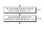
도 5b를 참조하면, 전자 장치는 제 1 충전회로를 이용하여 유선 연결 장치로 전원을 공급하는 수단(511)과 무선 충전 장치로부터 전원을 공급받고, 제 2 충전회로를 이용하여 무선 충전 장치로부터 공급되는 전원으로 배터리를 충전하는 수단(513)을 포함한다.
Referring to FIG. 5B, the electronic device includes a
도 6a는 본 발명에 따른 전자 장치에서 유선 충전 절차를 도시하고 있다.6A shows a wired charging procedure in an electronic device according to the present invention.
도 6a를 참조하면, 전자 장치는 601단계에서 전자 장치에 연결된 유선 충전 장치에 따라 복수의 충전회로 중에서 하나의 충전회로를 선택한다. 이때, 전자 장치는 유선 충전 장치의 ID, 타입 및/혹은 충전 전류의 용량에 대응하는 충전회로를 선택한다. 이후, 전자 장치는 603단계로 진행하여 선택된 충전회로를 이용하여 유선 충전 장치로부터의 전원을 공급받아 배터리를 충전한다.
Referring to FIG. 6A, the electronic device selects one of the plurality of charging circuits in accordance with the wire charging apparatus connected to the electronic device in
도 6b는 본 발명에 따른 전자 장치에서 유선 충전 절차를 수행하기 위한 수단을 도시하고 있다.Figure 6b illustrates the means for performing a wired charging procedure in an electronic device according to the present invention.
도 6b를 참조하면, 전자 장치는 전자 장치에 연결된 유선 충전 장치에 따라 복수의 충전회로 중에서 하나의 충전회로를 선택하는 수단(611)과 선택된 충전회로를 이용하여 유선 충전 장치로부터의 전원을 공급받아 배터리를 충전하는 수단(613)을 포함한다. 이때, 전자 장치의 충전회로 선택 수단은 유선 충전 장치의 ID, 타입 및/혹은 충전 전류의 용량에 대응하는 충전회로를 선택한다.
6B, the electronic device includes a
한편 본 발명의 상세한 설명에서는 구체적인 실시 예에 관해 설명하였으나, 본 발명의 범위에서 벗어나지 않는 한도 내에서 여러 가지 변형이 가능하다. 그러므로 본 발명의 범위는 설명된 실시 예에 국한되어 정해져서는 아니 되며 후술하는 특허청구의 범위뿐만 아니라 이 특허청구의 범위와 균등한 것들에 의해 정해져야 한다.
While the present invention has been described in connection with what is presently considered to be the most practical and preferred embodiment, it is to be understood that the invention is not limited to the disclosed embodiments. Therefore, the scope of the present invention should not be limited by the illustrated embodiments, but should be determined by the scope of the appended claims and equivalents thereof.
Claims (20)
Translated fromKorean상기 모바일 단말의 배터리를 충전하기 위한 전원을 무선적으로 수신하기 위한 무선 충전 이벤트의 발생을 검출하는 동작과,
상기 무선 충전 이벤트의 발생을 검출하는 것에 기반하여, 상기 무선적으로 수신된 전원을 이용하여 상기 모바일 단말의 제1 충전 회로를 이용하여 상기 배터리를 충전하는 동작과,
상기 모바일 단말의 디스플레이를 통해 상기 모바일 단말이 무선 충전 중임을 나타내는 정보를 표시하는 동작과,
상기 무선적으로 수신된 전원을 이용하여 상기 배터리를 충전하는 동안, 유선 연결을 통해 상기 모바일 단말에 연결된 다른 전자 장치를 식별하는 동작과,
상기 다른 전자 장치를 유선 충전 장치로 식별하는 것에 응답하여, 상기 모바일 단말의 제2 충전 회로를 이용하여 상기 유선 충전 장치로부터 공급된 전원으로 상기 배터리를 충전하는 동작과, 상기 제2 충전 회로를 이용하여 상기 배터리를 충전하는 동작은 상기 제1 충전 회로를 이용하여 상기 배터리를 충전하는 동작과 동시에 수행되고,
상기 다른 전자 장치를 유선 충전 장치가 아닌 것으로 식별하는 것에 응답하여, 상기 제2 충전 회로를 이용하여 상기 배터리로부터, 상기 다른 전자 장치에게 전원을 공급하는 동작을 포함하고, 상기 제2 충전 회로를 이용하여 상기 다른 전자 장치에게 전원을 공급하는 동작은 상기 제1 충전 회로를 이용하여 상기 배터리를 충전하는 동작과 동시에 수행되는 방법.
A method of operating a mobile terminal,
Detecting an occurrence of a wireless charging event for wirelessly receiving power for charging the battery of the mobile terminal;
Charging the battery using the first charging circuit of the mobile terminal using the wirelessly received power based on detecting the occurrence of the wireless charging event;
Displaying information indicating that the mobile terminal is being wirelessly charged through a display of the mobile terminal;
Identifying another electronic device connected to the mobile terminal via a wired connection while charging the battery using the wirelessly received power source;
In response to identifying the other electronic device as a wired charging device, charging the battery with power supplied from the wired charging device using a second charging circuit of the mobile terminal; and using the second charging circuit The operation of charging the battery is performed simultaneously with the operation of charging the battery using the first charging circuit,
Supplying power from the battery to the other electronic device using the second charging circuit in response to identifying the other electronic device as being not a wired charging device, Wherein the operation of supplying power to the other electronic device is performed simultaneously with the operation of charging the battery using the first charging circuit.
상기 모바일 단말 및 상기 다른 전자 장치는, 각각 이동 전화를 포함하는 방법.
The method according to claim 1,
Wherein the mobile terminal and the other electronic device each include a mobile telephone.
상기 모바일 단말은 태블릿 컴퓨터를 포함하는 방법.
The method according to claim 1,
Wherein the mobile terminal comprises a tablet computer.
상기 무선 충전 이벤트의 발생을 검출하는 동작은, 무선 충전 장치에 의해 공급된 전원을 검출하는 동작을 포함하는 방법.
The method according to claim 1,
Wherein detecting the occurrence of the wireless charging event comprises detecting power supplied by the wireless charging device.
상기 무선 충전 장치에 의해 공급된 전원을 검출하는 동작은, 유도 전류를 검출하는 동작을 포함하는 방법.
5. The method of claim 4,
Wherein the operation of detecting the power supplied by the wireless charging device includes detecting an induced current.
상기 유선 연결은, USB (Universal Serial Bus) 연결을 포함하는 방법.
The method according to claim 1,
Wherein the wired connection comprises a Universal Serial Bus (USB) connection.
상기 USB 연결은, USB OTG (Open-The-Go) 연결을 포함하는 방법.
The method according to claim 6,
Wherein the USB connection comprises a USB Open-The-Go (OTG) connection.
디스플레이;
제1 충전 회로;
제2 충전 회로;
배터리; 및
프로세서를 포함하고, 상기 프로세서는,
상기 배터리를 충전하기 위한 전원을 무선적으로 수신하기 위한 무선 충전 이벤트의 발생을 검출하고,
상기 무선 충전 이벤트의 발생을 검출하는 것에 기반하여, 상기 무선적으로 수신된 전원을 이용하여 상기 제1 충전 회로를 이용하여 상기 배터리를 충전하고,
상기 디스플레이를 통해 상기 모바일 단말이 무선 충전 중임을 나타내는 정보를 표시하고,
상기 무선적으로 수신된 전원을 이용하여 상기 배터리를 충전하는 동안, 유선 연결을 통해 상기 모바일 단말에 연결된 다른 전자 장치를 식별하고,
상기 다른 전자 장치를 유선 충전 장치로 식별하는 것에 응답하여, 상기 제2 충전 회로를 이용하여 상기 유선 충전 장치로부터 공급된 전원으로 상기 배터리를 충전하고, 상기 제2 충전 회로를 이용하여 상기 배터리를 충전하는 동작은, 상기 제1 충전 회로를 이용하여 상기 배터리를 충전하는 동작과 동시에 수행되고,
상기 다른 전자 장치를 유선 충전 장치가 아닌 것으로 식별하는 것에 응답하여, 상기 제2 충전 회로를 이용하여 상기 배터리로부터, 상기 다른 전자 장치에게 전원을 공급하도록 설정되고, 상기 제2 충전 회로를 이용하여 상기 다른 전자 장치에게 전원을 공급하는 동작은, 상기 제1 충전 회로를 이용하여 상기 배터리를 충전하는 동작과 동시에 수행되는 모바일 단말.
In a mobile terminal,
display;
A first charging circuit;
A second charging circuit;
battery; And
The processor comprising:
Detecting occurrence of a wireless charging event for wirelessly receiving power for charging the battery,
Based on detecting the occurrence of the wireless charging event, charging the battery using the first charging circuit using the wirelessly received power source,
Displaying information indicating that the mobile terminal is being wirelessly charged through the display,
Identifying another electronic device connected to the mobile terminal via a wired connection while charging the battery using the wirelessly received power source,
In response to identifying the other electronic device as a wired charging device, charging the battery with power supplied from the wired charging device using the second charging circuit, charging the battery using the second charging circuit Is performed simultaneously with the operation of charging the battery using the first charging circuit,
In response to identifying the other electronic device as being not a wired charging device, is set to supply power from the battery to the other electronic device using the second charging circuit, The operation of supplying power to another electronic device is performed simultaneously with the operation of charging the battery using the first charging circuit.
상기 모바일 단말 및 상기 다른 전자 장치는, 각각 이동 전화를 포함하는 모바일 단말.
11. The method of claim 10,
Wherein the mobile terminal and the other electronic device each include a mobile telephone.
태블릿 컴퓨터를 포함하는 모바일 단말.
11. The method of claim 10,
A mobile terminal comprising a tablet computer.
상기 제1 충전 회로는, 무선 충전 장치에 의해 공급된 전원을 검출함으로써 무선 충전 이벤트의 발생을 검출하도록 설정된 모바일 단말.
11. The method of claim 10,
Wherein the first charging circuit is configured to detect occurrence of a wireless charging event by detecting power supplied by the wireless charging device.
상기 제1 충전 회로는, 유도 전류를 검출함으로써 상기 무선 충전 장치에 의해 공급된 전원을 검출하도록 설정된 모바일 단말.
14. The method of claim 13,
Wherein the first charging circuit is configured to detect the power supplied by the wireless charging device by detecting an inductive current.
상기 유선 연결은, USB (Universal Serial Bus) 연결을 포함하는 모바일 단말.
11. The method of claim 10,
The wired connection includes a universal serial bus (USB) connection.
상기 USB 연결은, USB OTG (Open-The-Go) 연결을 포함하는 모바일 단말.
16. The method of claim 15,
The USB connection includes a USB Open-The-Go (OTG) connection.
Priority Applications (17)
| Application Number | Priority Date | Filing Date | Title |
|---|---|---|---|
| KR1020120065421AKR101920236B1 (en) | 2012-06-19 | 2012-06-19 | Method for charging battery and an electronic device thereof |
| US13/908,311US9787130B2 (en) | 2012-06-19 | 2013-06-03 | Battery charging method and electronic device |
| CA2874458ACA2874458C (en) | 2012-06-19 | 2013-06-14 | Battery charging method and electronic device |
| RU2014151569/07ARU2583151C1 (en) | 2012-06-19 | 2013-06-14 | Battery charging method and electronic device |
| EP23192668.4AEP4290735A3 (en) | 2012-06-19 | 2013-06-14 | Battery charging method and electronic device |
| BR112014032041-1ABR112014032041B1 (en) | 2012-06-19 | 2013-06-14 | METHOD FOR OPERATING AN ELECTRONIC DEVICE AND ELECTRONIC DEVICE |
| ES13172167TES2961665T3 (en) | 2012-06-19 | 2013-06-14 | Battery and electronic device charging procedure |
| EP13172167.2AEP2677625B1 (en) | 2012-06-19 | 2013-06-14 | Battery charging method and electronic device |
| PCT/KR2013/005288WO2013191416A1 (en) | 2012-06-19 | 2013-06-14 | Battery charging method and electronic device |
| AU2013206416AAU2013206416A1 (en) | 2012-06-19 | 2013-06-19 | Battery charging method and electronic device |
| JP2013128547AJP2014003889A (en) | 2012-06-19 | 2013-06-19 | Battery charging method of electronic device and electronic device |
| CN201310242860.1ACN103516014B (en) | 2012-06-19 | 2013-06-19 | Battery charging method and electronic device |
| CN201910085235.8ACN109768598A (en) | 2012-06-19 | 2013-06-19 | Battery charging method and electronic device |
| AU2015246085AAU2015246085B2 (en) | 2012-06-19 | 2015-10-20 | Battery charging method and electronic device |
| US15/715,042US10374450B2 (en) | 2012-06-19 | 2017-09-25 | Battery charging method and electronic device |
| US16/532,257US11368039B2 (en) | 2012-06-19 | 2019-08-05 | Battery charging method and electronic device |
| US17/751,162US12189445B2 (en) | 2012-06-19 | 2022-05-23 | Battery charging method and electronic device |
Applications Claiming Priority (1)
| Application Number | Priority Date | Filing Date | Title |
|---|---|---|---|
| KR1020120065421AKR101920236B1 (en) | 2012-06-19 | 2012-06-19 | Method for charging battery and an electronic device thereof |
Publications (2)
| Publication Number | Publication Date |
|---|---|
| KR20130142312A KR20130142312A (en) | 2013-12-30 |
| KR101920236B1true KR101920236B1 (en) | 2018-11-20 |
Family
ID=48613512
Family Applications (1)
| Application Number | Title | Priority Date | Filing Date |
|---|---|---|---|
| KR1020120065421AActiveKR101920236B1 (en) | 2012-06-19 | 2012-06-19 | Method for charging battery and an electronic device thereof |
Country Status (10)
| Country | Link |
|---|---|
| US (4) | US9787130B2 (en) |
| EP (2) | EP4290735A3 (en) |
| JP (1) | JP2014003889A (en) |
| KR (1) | KR101920236B1 (en) |
| CN (2) | CN109768598A (en) |
| AU (2) | AU2013206416A1 (en) |
| CA (1) | CA2874458C (en) |
| ES (1) | ES2961665T3 (en) |
| RU (1) | RU2583151C1 (en) |
| WO (1) | WO2013191416A1 (en) |
Cited By (3)
| Publication number | Priority date | Publication date | Assignee | Title |
|---|---|---|---|---|
| KR20210013958A (en) | 2019-07-29 | 2021-02-08 | 정찬빈 | Rechargeable Wire Controled Anti-Barking Spray Collar |
| KR20220002505U (en)* | 2021-04-12 | 2022-10-19 | 주식회사 이젠 | Electronic device for vehicle |
| WO2023239037A1 (en)* | 2022-06-10 | 2023-12-14 | 삼성전자 주식회사 | Electronic device and method for wirelessly transmitting or receiving power |
Families Citing this family (250)
| Publication number | Priority date | Publication date | Assignee | Title |
|---|---|---|---|---|
| KR101920236B1 (en) | 2012-06-19 | 2018-11-20 | 삼성전자주식회사 | Method for charging battery and an electronic device thereof |
| US9853458B1 (en) | 2014-05-07 | 2017-12-26 | Energous Corporation | Systems and methods for device and power receiver pairing |
| US10291066B1 (en) | 2014-05-07 | 2019-05-14 | Energous Corporation | Power transmission control systems and methods |
| US9867062B1 (en) | 2014-07-21 | 2018-01-09 | Energous Corporation | System and methods for using a remote server to authorize a receiving device that has requested wireless power and to determine whether another receiving device should request wireless power in a wireless power transmission system |
| US10199835B2 (en) | 2015-12-29 | 2019-02-05 | Energous Corporation | Radar motion detection using stepped frequency in wireless power transmission system |
| US10218227B2 (en) | 2014-05-07 | 2019-02-26 | Energous Corporation | Compact PIFA antenna |
| US10224982B1 (en) | 2013-07-11 | 2019-03-05 | Energous Corporation | Wireless power transmitters for transmitting wireless power and tracking whether wireless power receivers are within authorized locations |
| US10193396B1 (en) | 2014-05-07 | 2019-01-29 | Energous Corporation | Cluster management of transmitters in a wireless power transmission system |
| US10211674B1 (en) | 2013-06-12 | 2019-02-19 | Energous Corporation | Wireless charging using selected reflectors |
| US10050462B1 (en) | 2013-08-06 | 2018-08-14 | Energous Corporation | Social power sharing for mobile devices based on pocket-forming |
| US9787103B1 (en) | 2013-08-06 | 2017-10-10 | Energous Corporation | Systems and methods for wirelessly delivering power to electronic devices that are unable to communicate with a transmitter |
| US10291055B1 (en) | 2014-12-29 | 2019-05-14 | Energous Corporation | Systems and methods for controlling far-field wireless power transmission based on battery power levels of a receiving device |
| US10090886B1 (en) | 2014-07-14 | 2018-10-02 | Energous Corporation | System and method for enabling automatic charging schedules in a wireless power network to one or more devices |
| US9812890B1 (en) | 2013-07-11 | 2017-11-07 | Energous Corporation | Portable wireless charging pad |
| US11502551B2 (en) | 2012-07-06 | 2022-11-15 | Energous Corporation | Wirelessly charging multiple wireless-power receivers using different subsets of an antenna array to focus energy at different locations |
| US10256657B2 (en) | 2015-12-24 | 2019-04-09 | Energous Corporation | Antenna having coaxial structure for near field wireless power charging |
| US10263432B1 (en) | 2013-06-25 | 2019-04-16 | Energous Corporation | Multi-mode transmitter with an antenna array for delivering wireless power and providing Wi-Fi access |
| US9973021B2 (en) | 2012-07-06 | 2018-05-15 | Energous Corporation | Receivers for wireless power transmission |
| US12057715B2 (en) | 2012-07-06 | 2024-08-06 | Energous Corporation | Systems and methods of wirelessly delivering power to a wireless-power receiver device in response to a change of orientation of the wireless-power receiver device |
| US20140008993A1 (en) | 2012-07-06 | 2014-01-09 | DvineWave Inc. | Methodology for pocket-forming |
| US9876379B1 (en) | 2013-07-11 | 2018-01-23 | Energous Corporation | Wireless charging and powering of electronic devices in a vehicle |
| US9843201B1 (en) | 2012-07-06 | 2017-12-12 | Energous Corporation | Wireless power transmitter that selects antenna sets for transmitting wireless power to a receiver based on location of the receiver, and methods of use thereof |
| US9831718B2 (en) | 2013-07-25 | 2017-11-28 | Energous Corporation | TV with integrated wireless power transmitter |
| US10312715B2 (en) | 2015-09-16 | 2019-06-04 | Energous Corporation | Systems and methods for wireless power charging |
| US10439448B2 (en) | 2014-08-21 | 2019-10-08 | Energous Corporation | Systems and methods for automatically testing the communication between wireless power transmitter and wireless power receiver |
| US10128693B2 (en) | 2014-07-14 | 2018-11-13 | Energous Corporation | System and method for providing health safety in a wireless power transmission system |
| US10148097B1 (en) | 2013-11-08 | 2018-12-04 | Energous Corporation | Systems and methods for using a predetermined number of communication channels of a wireless power transmitter to communicate with different wireless power receivers |
| US10008889B2 (en) | 2014-08-21 | 2018-06-26 | Energous Corporation | Method for automatically testing the operational status of a wireless power receiver in a wireless power transmission system |
| US9847679B2 (en) | 2014-05-07 | 2017-12-19 | Energous Corporation | System and method for controlling communication between wireless power transmitter managers |
| US9954374B1 (en) | 2014-05-23 | 2018-04-24 | Energous Corporation | System and method for self-system analysis for detecting a fault in a wireless power transmission Network |
| US9838083B2 (en) | 2014-07-21 | 2017-12-05 | Energous Corporation | Systems and methods for communication with remote management systems |
| US10230266B1 (en) | 2014-02-06 | 2019-03-12 | Energous Corporation | Wireless power receivers that communicate status data indicating wireless power transmission effectiveness with a transmitter using a built-in communications component of a mobile device, and methods of use thereof |
| US10223717B1 (en) | 2014-05-23 | 2019-03-05 | Energous Corporation | Systems and methods for payment-based authorization of wireless power transmission service |
| US9941754B2 (en) | 2012-07-06 | 2018-04-10 | Energous Corporation | Wireless power transmission with selective range |
| US9843213B2 (en) | 2013-08-06 | 2017-12-12 | Energous Corporation | Social power sharing for mobile devices based on pocket-forming |
| US9859797B1 (en) | 2014-05-07 | 2018-01-02 | Energous Corporation | Synchronous rectifier design for wireless power receiver |
| US10205239B1 (en) | 2014-05-07 | 2019-02-12 | Energous Corporation | Compact PIFA antenna |
| US10103582B2 (en) | 2012-07-06 | 2018-10-16 | Energous Corporation | Transmitters for wireless power transmission |
| US20150326070A1 (en) | 2014-05-07 | 2015-11-12 | Energous Corporation | Methods and Systems for Maximum Power Point Transfer in Receivers |
| US10211680B2 (en) | 2013-07-19 | 2019-02-19 | Energous Corporation | Method for 3 dimensional pocket-forming |
| US9991741B1 (en) | 2014-07-14 | 2018-06-05 | Energous Corporation | System for tracking and reporting status and usage information in a wireless power management system |
| US10243414B1 (en) | 2014-05-07 | 2019-03-26 | Energous Corporation | Wearable device with wireless power and payload receiver |
| US9966765B1 (en) | 2013-06-25 | 2018-05-08 | Energous Corporation | Multi-mode transmitter |
| US10211682B2 (en) | 2014-05-07 | 2019-02-19 | Energous Corporation | Systems and methods for controlling operation of a transmitter of a wireless power network based on user instructions received from an authenticated computing device powered or charged by a receiver of the wireless power network |
| US9906065B2 (en) | 2012-07-06 | 2018-02-27 | Energous Corporation | Systems and methods of transmitting power transmission waves based on signals received at first and second subsets of a transmitter's antenna array |
| US9252628B2 (en) | 2013-05-10 | 2016-02-02 | Energous Corporation | Laptop computer as a transmitter for wireless charging |
| US10992187B2 (en) | 2012-07-06 | 2021-04-27 | Energous Corporation | System and methods of using electromagnetic waves to wirelessly deliver power to electronic devices |
| US10199849B1 (en) | 2014-08-21 | 2019-02-05 | Energous Corporation | Method for automatically testing the operational status of a wireless power receiver in a wireless power transmission system |
| US9859756B2 (en) | 2012-07-06 | 2018-01-02 | Energous Corporation | Transmittersand methods for adjusting wireless power transmission based on information from receivers |
| US9912199B2 (en) | 2012-07-06 | 2018-03-06 | Energous Corporation | Receivers for wireless power transmission |
| US10038337B1 (en) | 2013-09-16 | 2018-07-31 | Energous Corporation | Wireless power supply for rescue devices |
| US9923386B1 (en) | 2012-07-06 | 2018-03-20 | Energous Corporation | Systems and methods for wireless power transmission by modifying a number of antenna elements used to transmit power waves to a receiver |
| US10992185B2 (en) | 2012-07-06 | 2021-04-27 | Energous Corporation | Systems and methods of using electromagnetic waves to wirelessly deliver power to game controllers |
| US9847677B1 (en) | 2013-10-10 | 2017-12-19 | Energous Corporation | Wireless charging and powering of healthcare gadgets and sensors |
| US9899873B2 (en) | 2014-05-23 | 2018-02-20 | Energous Corporation | System and method for generating a power receiver identifier in a wireless power network |
| US9893554B2 (en) | 2014-07-14 | 2018-02-13 | Energous Corporation | System and method for providing health safety in a wireless power transmission system |
| US9806564B2 (en) | 2014-05-07 | 2017-10-31 | Energous Corporation | Integrated rectifier and boost converter for wireless power transmission |
| US9825674B1 (en) | 2014-05-23 | 2017-11-21 | Energous Corporation | Enhanced transmitter that selects configurations of antenna elements for performing wireless power transmission and receiving functions |
| US10224758B2 (en) | 2013-05-10 | 2019-03-05 | Energous Corporation | Wireless powering of electronic devices with selective delivery range |
| US9438045B1 (en) | 2013-05-10 | 2016-09-06 | Energous Corporation | Methods and systems for maximum power point transfer in receivers |
| US10381880B2 (en) | 2014-07-21 | 2019-08-13 | Energous Corporation | Integrated antenna structure arrays for wireless power transmission |
| US9899861B1 (en) | 2013-10-10 | 2018-02-20 | Energous Corporation | Wireless charging methods and systems for game controllers, based on pocket-forming |
| US9876394B1 (en) | 2014-05-07 | 2018-01-23 | Energous Corporation | Boost-charger-boost system for enhanced power delivery |
| US9124125B2 (en) | 2013-05-10 | 2015-09-01 | Energous Corporation | Wireless power transmission with selective range |
| US10124754B1 (en) | 2013-07-19 | 2018-11-13 | Energous Corporation | Wireless charging and powering of electronic sensors in a vehicle |
| US9887739B2 (en) | 2012-07-06 | 2018-02-06 | Energous Corporation | Systems and methods for wireless power transmission by comparing voltage levels associated with power waves transmitted by antennas of a plurality of antennas of a transmitter to determine appropriate phase adjustments for the power waves |
| US10128699B2 (en) | 2014-07-14 | 2018-11-13 | Energous Corporation | Systems and methods of providing wireless power using receiver device sensor inputs |
| US9948135B2 (en) | 2015-09-22 | 2018-04-17 | Energous Corporation | Systems and methods for identifying sensitive objects in a wireless charging transmission field |
| US10063105B2 (en) | 2013-07-11 | 2018-08-28 | Energous Corporation | Proximity transmitters for wireless power charging systems |
| US9893768B2 (en) | 2012-07-06 | 2018-02-13 | Energous Corporation | Methodology for multiple pocket-forming |
| US10063064B1 (en) | 2014-05-23 | 2018-08-28 | Energous Corporation | System and method for generating a power receiver identifier in a wireless power network |
| US9876648B2 (en) | 2014-08-21 | 2018-01-23 | Energous Corporation | System and method to control a wireless power transmission system by configuration of wireless power transmission control parameters |
| US10141791B2 (en) | 2014-05-07 | 2018-11-27 | Energous Corporation | Systems and methods for controlling communications during wireless transmission of power using application programming interfaces |
| US10141768B2 (en) | 2013-06-03 | 2018-11-27 | Energous Corporation | Systems and methods for maximizing wireless power transfer efficiency by instructing a user to change a receiver device's position |
| US9893555B1 (en) | 2013-10-10 | 2018-02-13 | Energous Corporation | Wireless charging of tools using a toolbox transmitter |
| US10090699B1 (en) | 2013-11-01 | 2018-10-02 | Energous Corporation | Wireless powered house |
| US9939864B1 (en) | 2014-08-21 | 2018-04-10 | Energous Corporation | System and method to control a wireless power transmission system by configuration of wireless power transmission control parameters |
| US10186913B2 (en) | 2012-07-06 | 2019-01-22 | Energous Corporation | System and methods for pocket-forming based on constructive and destructive interferences to power one or more wireless power receivers using a wireless power transmitter including a plurality of antennas |
| US10965164B2 (en) | 2012-07-06 | 2021-03-30 | Energous Corporation | Systems and methods of wirelessly delivering power to a receiver device |
| US9882427B2 (en) | 2013-05-10 | 2018-01-30 | Energous Corporation | Wireless power delivery using a base station to control operations of a plurality of wireless power transmitters |
| US10206185B2 (en) | 2013-05-10 | 2019-02-12 | Energous Corporation | System and methods for wireless power transmission to an electronic device in accordance with user-defined restrictions |
| US10270261B2 (en) | 2015-09-16 | 2019-04-23 | Energous Corporation | Systems and methods of object detection in wireless power charging systems |
| US9871398B1 (en) | 2013-07-01 | 2018-01-16 | Energous Corporation | Hybrid charging method for wireless power transmission based on pocket-forming |
| US10063106B2 (en) | 2014-05-23 | 2018-08-28 | Energous Corporation | System and method for a self-system analysis in a wireless power transmission network |
| KR102158288B1 (en)* | 2012-07-09 | 2020-09-21 | 삼성전자주식회사 | Method for charging battery and an electronic device thereof |
| JP2014176170A (en)* | 2013-03-07 | 2014-09-22 | Toshiba Corp | Power incoming apparatus and charging system |
| US9912016B2 (en)* | 2013-04-08 | 2018-03-06 | Ford Meazell | Link for battery power transfer between portable electronic devices |
| US9537357B2 (en) | 2013-05-10 | 2017-01-03 | Energous Corporation | Wireless sound charging methods and systems for game controllers, based on pocket-forming |
| US9538382B2 (en) | 2013-05-10 | 2017-01-03 | Energous Corporation | System and method for smart registration of wireless power receivers in a wireless power network |
| US10103552B1 (en) | 2013-06-03 | 2018-10-16 | Energous Corporation | Protocols for authenticated wireless power transmission |
| US10021523B2 (en) | 2013-07-11 | 2018-07-10 | Energous Corporation | Proximity transmitters for wireless power charging systems |
| US9979440B1 (en) | 2013-07-25 | 2018-05-22 | Energous Corporation | Antenna tile arrangements configured to operate as one functional unit |
| KR102252525B1 (en)* | 2014-06-23 | 2021-05-17 | 에스케이플래닛 주식회사 | Wireless charging equipment, terminal, wireless charging system comprising the same, control method thereof and computer readable medium having computer program recorded therefor |
| US9935482B1 (en) | 2014-02-06 | 2018-04-03 | Energous Corporation | Wireless power transmitters that transmit at determined times based on power availability and consumption at a receiving mobile device |
| US10075017B2 (en) | 2014-02-06 | 2018-09-11 | Energous Corporation | External or internal wireless power receiver with spaced-apart antenna elements for charging or powering mobile devices using wirelessly delivered power |
| EP3098931B1 (en)* | 2014-03-04 | 2019-09-11 | Huawei Device Co., Ltd. | Charging circuit and terminal |
| CN103887571A (en)* | 2014-03-28 | 2014-06-25 | 乐视致新电子科技(天津)有限公司 | Charging mode switching method and charging mode switching device |
| KR102312362B1 (en)* | 2014-06-23 | 2021-10-13 | 에스케이플래닛 주식회사 | Wireless charging equipment, terminal, service providing device, wireless charging system comprising the same, control method thereof and computer readable medium having computer program recorded therefor |
| US10158257B2 (en) | 2014-05-01 | 2018-12-18 | Energous Corporation | System and methods for using sound waves to wirelessly deliver power to electronic devices |
| US9966784B2 (en) | 2014-06-03 | 2018-05-08 | Energous Corporation | Systems and methods for extending battery life of portable electronic devices charged by sound |
| US10170917B1 (en) | 2014-05-07 | 2019-01-01 | Energous Corporation | Systems and methods for managing and controlling a wireless power network by establishing time intervals during which receivers communicate with a transmitter |
| US10153645B1 (en) | 2014-05-07 | 2018-12-11 | Energous Corporation | Systems and methods for designating a master power transmitter in a cluster of wireless power transmitters |
| US10153653B1 (en) | 2014-05-07 | 2018-12-11 | Energous Corporation | Systems and methods for using application programming interfaces to control communications between a transmitter and a receiver |
| US9800172B1 (en) | 2014-05-07 | 2017-10-24 | Energous Corporation | Integrated rectifier and boost converter for boosting voltage received from wireless power transmission waves |
| KR101504068B1 (en)* | 2014-06-27 | 2015-03-19 | 주식회사 에프아이티글로벌 | Transmission system for providing customized wireless recharge |
| JP5986145B2 (en)* | 2014-07-02 | 2016-09-06 | レノボ・シンガポール・プライベート・リミテッド | Portable devices, cable assemblies and USB systems |
| US9871301B2 (en) | 2014-07-21 | 2018-01-16 | Energous Corporation | Integrated miniature PIFA with artificial magnetic conductor metamaterials |
| US10068703B1 (en) | 2014-07-21 | 2018-09-04 | Energous Corporation | Integrated miniature PIFA with artificial magnetic conductor metamaterials |
| US10116143B1 (en) | 2014-07-21 | 2018-10-30 | Energous Corporation | Integrated antenna arrays for wireless power transmission |
| US9965009B1 (en) | 2014-08-21 | 2018-05-08 | Energous Corporation | Systems and methods for assigning a power receiver to individual power transmitters based on location of the power receiver |
| US9917477B1 (en) | 2014-08-21 | 2018-03-13 | Energous Corporation | Systems and methods for automatically testing the communication between power transmitter and wireless receiver |
| CN104269585B (en)* | 2014-10-17 | 2016-09-28 | 广东欧珀移动通信有限公司 | A kind of charging method and mobile terminal |
| US10122415B2 (en) | 2014-12-27 | 2018-11-06 | Energous Corporation | Systems and methods for assigning a set of antennas of a wireless power transmitter to a wireless power receiver based on a location of the wireless power receiver |
| CN104578372B (en)* | 2015-01-15 | 2018-04-27 | 小米科技有限责任公司 | The method and device of control terminal equipment charge |
| CN106200442B (en)* | 2015-04-30 | 2021-04-09 | 中兴通讯股份有限公司 | Method and device for realizing connection control |
| KR102378373B1 (en)* | 2015-05-26 | 2022-03-25 | 삼성전자주식회사 | Device For Using Multiple Charging Circuits and Method Thereof |
| KR102483835B1 (en)* | 2015-07-06 | 2023-01-03 | 삼성전자주식회사 | Method for transmitting and receving power and electronic device thereof |
| KR102184527B1 (en)* | 2015-08-19 | 2020-11-30 | 삼성전자주식회사 | Electronic apparatus and method for wire and wireless charging in electronic apparatus |
| KR102369202B1 (en)* | 2015-08-19 | 2022-03-03 | 삼성전자주식회사 | Electronic apparatus and method for wire and wireless charging in electronic apparatus |
| KR102445714B1 (en) | 2015-08-28 | 2022-09-23 | 삼성전자 주식회사 | A method for charging a battery and an electronic device implementing the same |
| US9906275B2 (en) | 2015-09-15 | 2018-02-27 | Energous Corporation | Identifying receivers in a wireless charging transmission field |
| US12283828B2 (en) | 2015-09-15 | 2025-04-22 | Energous Corporation | Receiver devices configured to determine location within a transmission field |
| US10523033B2 (en) | 2015-09-15 | 2019-12-31 | Energous Corporation | Receiver devices configured to determine location within a transmission field |
| US10008875B1 (en) | 2015-09-16 | 2018-06-26 | Energous Corporation | Wireless power transmitter configured to transmit power waves to a predicted location of a moving wireless power receiver |
| US10211685B2 (en) | 2015-09-16 | 2019-02-19 | Energous Corporation | Systems and methods for real or near real time wireless communications between a wireless power transmitter and a wireless power receiver |
| US9941752B2 (en) | 2015-09-16 | 2018-04-10 | Energous Corporation | Systems and methods of object detection in wireless power charging systems |
| US10199850B2 (en) | 2015-09-16 | 2019-02-05 | Energous Corporation | Systems and methods for wirelessly transmitting power from a transmitter to a receiver by determining refined locations of the receiver in a segmented transmission field associated with the transmitter |
| US9893538B1 (en) | 2015-09-16 | 2018-02-13 | Energous Corporation | Systems and methods of object detection in wireless power charging systems |
| US10158259B1 (en) | 2015-09-16 | 2018-12-18 | Energous Corporation | Systems and methods for identifying receivers in a transmission field by transmitting exploratory power waves towards different segments of a transmission field |
| US10186893B2 (en) | 2015-09-16 | 2019-01-22 | Energous Corporation | Systems and methods for real time or near real time wireless communications between a wireless power transmitter and a wireless power receiver |
| US10778041B2 (en) | 2015-09-16 | 2020-09-15 | Energous Corporation | Systems and methods for generating power waves in a wireless power transmission system |
| US9871387B1 (en) | 2015-09-16 | 2018-01-16 | Energous Corporation | Systems and methods of object detection using one or more video cameras in wireless power charging systems |
| US11710321B2 (en) | 2015-09-16 | 2023-07-25 | Energous Corporation | Systems and methods of object detection in wireless power charging systems |
| US10135294B1 (en) | 2015-09-22 | 2018-11-20 | Energous Corporation | Systems and methods for preconfiguring transmission devices for power wave transmissions based on location data of one or more receivers |
| US10027168B2 (en) | 2015-09-22 | 2018-07-17 | Energous Corporation | Systems and methods for generating and transmitting wireless power transmission waves using antennas having a spacing that is selected by the transmitter |
| US10020678B1 (en) | 2015-09-22 | 2018-07-10 | Energous Corporation | Systems and methods for selecting antennas to generate and transmit power transmission waves |
| US10050470B1 (en) | 2015-09-22 | 2018-08-14 | Energous Corporation | Wireless power transmission device having antennas oriented in three dimensions |
| US10153660B1 (en) | 2015-09-22 | 2018-12-11 | Energous Corporation | Systems and methods for preconfiguring sensor data for wireless charging systems |
| US10033222B1 (en) | 2015-09-22 | 2018-07-24 | Energous Corporation | Systems and methods for determining and generating a waveform for wireless power transmission waves |
| US10135295B2 (en) | 2015-09-22 | 2018-11-20 | Energous Corporation | Systems and methods for nullifying energy levels for wireless power transmission waves |
| US10128686B1 (en) | 2015-09-22 | 2018-11-13 | Energous Corporation | Systems and methods for identifying receiver locations using sensor technologies |
| US10734717B2 (en) | 2015-10-13 | 2020-08-04 | Energous Corporation | 3D ceramic mold antenna |
| US10333332B1 (en) | 2015-10-13 | 2019-06-25 | Energous Corporation | Cross-polarized dipole antenna |
| US9899744B1 (en) | 2015-10-28 | 2018-02-20 | Energous Corporation | Antenna for wireless charging systems |
| US9853485B2 (en) | 2015-10-28 | 2017-12-26 | Energous Corporation | Antenna for wireless charging systems |
| US10027180B1 (en) | 2015-11-02 | 2018-07-17 | Energous Corporation | 3D triple linear antenna that acts as heat sink |
| US10063108B1 (en) | 2015-11-02 | 2018-08-28 | Energous Corporation | Stamped three-dimensional antenna |
| US10135112B1 (en) | 2015-11-02 | 2018-11-20 | Energous Corporation | 3D antenna mount |
| KR20170055866A (en)* | 2015-11-12 | 2017-05-22 | 엘지전자 주식회사 | Device and operation method thereof |
| US10038332B1 (en) | 2015-12-24 | 2018-07-31 | Energous Corporation | Systems and methods of wireless power charging through multiple receiving devices |
| US10320446B2 (en) | 2015-12-24 | 2019-06-11 | Energous Corporation | Miniaturized highly-efficient designs for near-field power transfer system |
| US10116162B2 (en) | 2015-12-24 | 2018-10-30 | Energous Corporation | Near field transmitters with harmonic filters for wireless power charging |
| US10027159B2 (en) | 2015-12-24 | 2018-07-17 | Energous Corporation | Antenna for transmitting wireless power signals |
| US11863001B2 (en) | 2015-12-24 | 2024-01-02 | Energous Corporation | Near-field antenna for wireless power transmission with antenna elements that follow meandering patterns |
| US10256677B2 (en) | 2016-12-12 | 2019-04-09 | Energous Corporation | Near-field RF charging pad with adaptive loading to efficiently charge an electronic device at any position on the pad |
| US10079515B2 (en) | 2016-12-12 | 2018-09-18 | Energous Corporation | Near-field RF charging pad with multi-band antenna element with adaptive loading to efficiently charge an electronic device at any position on the pad |
| JP7122591B2 (en)* | 2015-12-25 | 2022-08-22 | パナソニックIpマネジメント株式会社 | Electronics |
| US10008886B2 (en) | 2015-12-29 | 2018-06-26 | Energous Corporation | Modular antennas with heat sinks in wireless power transmission systems |
| US10142117B2 (en)* | 2016-04-11 | 2018-11-27 | Dell Products L.P. | Information handling system selective local and remote charger control |
| US10130152B2 (en)* | 2016-04-12 | 2018-11-20 | ARLO SKYE, Inc. | Electronic luggage device |
| WO2018032274A1 (en)* | 2016-08-15 | 2018-02-22 | 北京小米移动软件有限公司 | Electronic device, charger, charging system and charging method |
| JP6901248B2 (en)* | 2016-09-01 | 2021-07-14 | 東芝テック株式会社 | Information processing equipment and programs |
| KR102582596B1 (en)* | 2016-10-07 | 2023-09-25 | 삼성전자주식회사 | Method for charging battery and electronic apparatus |
| US10923954B2 (en) | 2016-11-03 | 2021-02-16 | Energous Corporation | Wireless power receiver with a synchronous rectifier |
| KR102185600B1 (en) | 2016-12-12 | 2020-12-03 | 에너저스 코포레이션 | A method of selectively activating antenna zones of a near field charging pad to maximize transmitted wireless power |
| CN106684978A (en)* | 2016-12-19 | 2017-05-17 | 宇龙计算机通信科技(深圳)有限公司 | Charging circuit, charging control method of charging circuit, and terminal |
| US10389161B2 (en) | 2017-03-15 | 2019-08-20 | Energous Corporation | Surface mount dielectric antennas for wireless power transmitters |
| US10439442B2 (en) | 2017-01-24 | 2019-10-08 | Energous Corporation | Microstrip antennas for wireless power transmitters |
| US10680319B2 (en) | 2017-01-06 | 2020-06-09 | Energous Corporation | Devices and methods for reducing mutual coupling effects in wireless power transmission systems |
| EP3367210A1 (en)* | 2017-02-24 | 2018-08-29 | Thomson Licensing | Method for operating a device and corresponding device, system, computer readable program product and computer readable storage medium |
| US11011942B2 (en) | 2017-03-30 | 2021-05-18 | Energous Corporation | Flat antennas having two or more resonant frequencies for use in wireless power transmission systems |
| EP3462564A4 (en)* | 2017-04-07 | 2019-05-08 | Guangdong Oppo Mobile Telecommunications Corp., Ltd. | SYSTEM, APPARATUS AND METHOD FOR WIRELESS LOADING, AND DEVICE FOR CHARGING |
| WO2018184285A1 (en) | 2017-04-07 | 2018-10-11 | 广东欧珀移动通信有限公司 | Wireless charging system, apparatus, method, and device to be charged |
| US10511097B2 (en) | 2017-05-12 | 2019-12-17 | Energous Corporation | Near-field antennas for accumulating energy at a near-field distance with minimal far-field gain |
| US12074452B2 (en) | 2017-05-16 | 2024-08-27 | Wireless Electrical Grid Lan, Wigl Inc. | Networked wireless charging system |
| US12074460B2 (en) | 2017-05-16 | 2024-08-27 | Wireless Electrical Grid Lan, Wigl Inc. | Rechargeable wireless power bank and method of using |
| US11462949B2 (en) | 2017-05-16 | 2022-10-04 | Wireless electrical Grid LAN, WiGL Inc | Wireless charging method and system |
| CN107147168B (en)* | 2017-05-27 | 2020-02-07 | 珠海市魅族科技有限公司 | Charging device and terminal equipment |
| CN106981908B (en)* | 2017-05-27 | 2019-11-15 | 珠海市魅族科技有限公司 | A kind of battery charge controller and terminal device |
| US10848853B2 (en) | 2017-06-23 | 2020-11-24 | Energous Corporation | Systems, methods, and devices for utilizing a wire of a sound-producing device as an antenna for receipt of wirelessly delivered power |
| US10122219B1 (en) | 2017-10-10 | 2018-11-06 | Energous Corporation | Systems, methods, and devices for using a battery as a antenna for receiving wirelessly delivered power from radio frequency power waves |
| US10804716B2 (en)* | 2017-10-13 | 2020-10-13 | Bose Corporation | Method and system for charging a battery |
| WO2019076012A1 (en)* | 2017-10-20 | 2019-04-25 | 华为技术有限公司 | Charging apparatus and terminal |
| US11342798B2 (en) | 2017-10-30 | 2022-05-24 | Energous Corporation | Systems and methods for managing coexistence of wireless-power signals and data signals operating in a same frequency band |
| CN108233468B (en)* | 2017-12-21 | 2020-08-28 | 维沃移动通信有限公司 | A charging method and mobile terminal |
| US10615647B2 (en) | 2018-02-02 | 2020-04-07 | Energous Corporation | Systems and methods for detecting wireless power receivers and other objects at a near-field charging pad |
| US11159057B2 (en) | 2018-03-14 | 2021-10-26 | Energous Corporation | Loop antennas with selectively-activated feeds to control propagation patterns of wireless power signals |
| US11515732B2 (en) | 2018-06-25 | 2022-11-29 | Energous Corporation | Power wave transmission techniques to focus wirelessly delivered power at a receiving device |
| CN109038863B (en)* | 2018-07-23 | 2020-08-14 | Oppo广东移动通信有限公司 | Electronic device |
| CN109120029B (en)* | 2018-08-14 | 2024-09-06 | Oppo广东移动通信有限公司 | Charging circuit, electronic device, charging management method and storage medium |
| CN109066870B (en)* | 2018-08-29 | 2021-07-20 | Oppo广东移动通信有限公司 | Charge management method, device, medium and electronic device applying the method |
| CN109066883B (en)* | 2018-09-03 | 2020-12-22 | Oppo广东移动通信有限公司 | Charging circuit, charging method and electronic device |
| CN109066882A (en)* | 2018-09-03 | 2018-12-21 | Oppo广东移动通信有限公司 | Charging circuit and electronic equipment |
| CN109217489A (en)* | 2018-09-05 | 2019-01-15 | Oppo广东移动通信有限公司 | Charging circuit, charging method, electronic device, and storage medium |
| CN109067019A (en)* | 2018-09-05 | 2018-12-21 | Oppo广东移动通信有限公司 | Charging and discharging circuit, method, electronic device and storage medium |
| CN109120034A (en)* | 2018-09-05 | 2019-01-01 | Oppo广东移动通信有限公司 | Charging circuit, charging method, electronic device and storage medium |
| CN109149697B (en)* | 2018-09-10 | 2022-06-14 | Oppo广东移动通信有限公司 | Charging circuit and electronic equipment |
| US11437735B2 (en) | 2018-11-14 | 2022-09-06 | Energous Corporation | Systems for receiving electromagnetic energy using antennas that are minimally affected by the presence of the human body |
| MX2020002393A (en) | 2018-12-21 | 2020-07-22 | Guangdong Oppo Mobile Telecommunications Corp Ltd | Charging control method and apparatus, and computer storage medium. |
| US10383482B1 (en)* | 2018-12-31 | 2019-08-20 | Miramore Inc. | Portable and rechargeable blender |
| US11539243B2 (en) | 2019-01-28 | 2022-12-27 | Energous Corporation | Systems and methods for miniaturized antenna for wireless power transmissions |
| EP3921945A1 (en) | 2019-02-06 | 2021-12-15 | Energous Corporation | Systems and methods of estimating optimal phases to use for individual antennas in an antenna array |
| US12155231B2 (en) | 2019-04-09 | 2024-11-26 | Energous Corporation | Asymmetric spiral antennas for wireless power transmission and reception |
| CN110518668A (en)* | 2019-09-05 | 2019-11-29 | 深圳传音控股股份有限公司 | For the quick charging system and method for handheld device, handheld device |
| KR102824743B1 (en)* | 2019-09-11 | 2025-06-24 | 삼성전자주식회사 | Charging management chip charging battery based on switching charging and direct charging and Operating method thereof |
| WO2021055901A1 (en) | 2019-09-20 | 2021-03-25 | Energous Corporation | Asymmetric spiral antennas with parasitic elements for wireless power transmission |
| US11381118B2 (en) | 2019-09-20 | 2022-07-05 | Energous Corporation | Systems and methods for machine learning based foreign object detection for wireless power transmission |
| WO2021055898A1 (en) | 2019-09-20 | 2021-03-25 | Energous Corporation | Systems and methods for machine learning based foreign object detection for wireless power transmission |
| WO2021055899A1 (en) | 2019-09-20 | 2021-03-25 | Energous Corporation | Systems and methods of protecting wireless power receivers using multiple rectifiers and establishing in-band communications using multiple rectifiers |
| CN114731061A (en) | 2019-09-20 | 2022-07-08 | 艾诺格思公司 | Classifying and detecting foreign objects using a power amplifier controller integrated circuit in a wireless power transmission system |
| US10702837B1 (en) | 2019-10-28 | 2020-07-07 | BlendJet, Inc. | Rechargeable blender with offset blades |
| USD948940S1 (en) | 2019-11-25 | 2022-04-19 | Blendjet Inc. | Base of a portable blender |
| USD905496S1 (en) | 2019-11-25 | 2020-12-22 | Blendjet Inc. | Portable blender |
| US10828612B1 (en) | 2019-11-25 | 2020-11-10 | Blendjet Inc. | Locking and unlocking a blender |
| KR20210064736A (en) | 2019-11-26 | 2021-06-03 | 삼성전자주식회사 | Electronic apparatus and charging method thereof |
| USD953103S1 (en) | 2019-11-26 | 2022-05-31 | Blendjet Inc. | Portable blender lid |
| USD908428S1 (en) | 2019-12-02 | 2021-01-26 | Blendjet Inc. | Removable jar of a portable blender |
| CN112928787B (en)* | 2019-12-06 | 2024-07-09 | 北京小米移动软件有限公司 | Charging circuit, electronic device, charging control method and device |
| USD911107S1 (en) | 2019-12-09 | 2021-02-23 | Blendjet Inc. | Button and light ring of a portable blender |
| US11355966B2 (en) | 2019-12-13 | 2022-06-07 | Energous Corporation | Charging pad with guiding contours to align an electronic device on the charging pad and efficiently transfer near-field radio-frequency energy to the electronic device |
| CN113113941A (en)* | 2019-12-24 | 2021-07-13 | Oppo广东移动通信有限公司 | Electronic device |
| US10985617B1 (en) | 2019-12-31 | 2021-04-20 | Energous Corporation | System for wirelessly transmitting energy at a near-field distance without using beam-forming control |
| US11799324B2 (en) | 2020-04-13 | 2023-10-24 | Energous Corporation | Wireless-power transmitting device for creating a uniform near-field charging area |
| CN113949167B (en)* | 2020-06-30 | 2023-05-16 | 荣耀终端有限公司 | Charging device and electronic equipment |
| KR102818458B1 (en) | 2020-07-29 | 2025-06-10 | 삼성전자주식회사 | Electronic device for prodiving power and operating method thereof |
| US11469629B2 (en) | 2020-08-12 | 2022-10-11 | Energous Corporation | Systems and methods for secure wireless transmission of power using unidirectional communication signals from a wireless-power-receiving device |
| CN115811106B (en)* | 2020-08-18 | 2023-10-31 | 荣耀终端有限公司 | Charging circuit, charging chip, electronic equipment and charging method |
| CN111969734B (en)* | 2020-09-21 | 2021-06-25 | 苏州普轮电子科技有限公司 | A kind of intelligent mutual inductance equipment charging management system and method |
| US11531403B2 (en) | 2020-10-06 | 2022-12-20 | Blendjet Inc. | One button interface of a blender |
| WO2022085924A1 (en)* | 2020-10-19 | 2022-04-28 | 주식회사 브로나인 | Power supply device, method, and program based on power specification analysis of connected electronic device |
| USD1007947S1 (en) | 2020-11-20 | 2023-12-19 | Blendjet Inc. | Battery-powered portable blender |
| USD981179S1 (en) | 2020-11-20 | 2023-03-21 | Blendjet Inc. | Base of a battery-powered portable blender |
| USD973437S1 (en) | 2020-11-20 | 2022-12-27 | Blendjet Inc. | Lid of a battery-powered portable blender |
| USD1007948S1 (en) | 2020-11-25 | 2023-12-19 | Blendjet Inc. | Removable jar of a battery-powered portable blender |
| USD1014178S1 (en) | 2020-11-25 | 2024-02-13 | Blendjet Inc. | Battery-powered portable blender |
| US12306285B2 (en) | 2020-12-01 | 2025-05-20 | Energous Corporation | Systems and methods for using one or more sensors to detect and classify objects in a keep-out zone of a wireless-power transmission field, and antennas with integrated sensor arrangements |
| US11690482B1 (en)* | 2020-12-10 | 2023-07-04 | Blendjet Inc. | Power boost mode for a blender |
| CN112865236B (en)* | 2021-01-22 | 2022-03-11 | 深圳市酷鱼互动科技有限公司 | Charging system capable of achieving wired and wireless intelligent switching, implementation method and charging equipment |
| US11824365B2 (en) | 2021-03-08 | 2023-11-21 | Blendjet Inc. | Portable blender with wireless charging |
| USD974841S1 (en) | 2021-03-08 | 2023-01-10 | Blendjet Inc. | Blade assembly for a portable blender |
| CN115133589A (en)* | 2021-03-24 | 2022-09-30 | 北京小米移动软件有限公司 | Charging and discharging system and terminal equipment |
| US11916398B2 (en) | 2021-12-29 | 2024-02-27 | Energous Corporation | Small form-factor devices with integrated and modular harvesting receivers, and shelving-mounted wireless-power transmitters for use therewith |
| USD1083507S1 (en) | 2022-03-11 | 2025-07-15 | Mavorco Operations Llc | Jar for a portable blender |
| USD1085813S1 (en) | 2022-03-11 | 2025-07-29 | Mavorco Operations Llc | Portable blender jar with handle |
| USD1085814S1 (en) | 2022-04-11 | 2025-07-29 | Mavorco Operations Llc | Jar of a portable blender |
| USD1028611S1 (en) | 2022-04-11 | 2024-05-28 | Blendjet Inc. | Portable blender lid |
| US12142939B2 (en) | 2022-05-13 | 2024-11-12 | Energous Corporation | Integrated wireless-power-transmission platform designed to operate in multiple bands, and multi-band antennas for use therewith |
| USD1059951S1 (en) | 2022-10-26 | 2025-02-04 | Blendjet Inc. | Portable blender jar |
| USD1043236S1 (en) | 2022-10-26 | 2024-09-24 | Blendjet Inc. | Portable blender lid |
| WO2024158128A1 (en)* | 2023-01-25 | 2024-08-02 | 삼성전자 주식회사 | Electronic device and wired/wireless charging control method in electronic device |
Citations (3)
| Publication number | Priority date | Publication date | Assignee | Title |
|---|---|---|---|---|
| US20080143290A1 (en)* | 2006-12-19 | 2008-06-19 | Anand Kumar Chavakula | Multi-Power Charger and Battery Backup System |
| JP2011118455A (en)* | 2009-11-30 | 2011-06-16 | Toshiba Corp | Information processor and control method in information processor |
| JP2012065537A (en)* | 2010-08-18 | 2012-03-29 | Sanyo Electric Co Ltd | Battery built-in device and charging apparatus |
Family Cites Families (100)
| Publication number | Priority date | Publication date | Assignee | Title |
|---|---|---|---|---|
| JP3125314B2 (en) | 1991-03-05 | 2001-01-15 | 井関農機株式会社 | Clamping rod mounting device for transfer carrier |
| JPH0564376A (en) | 1991-08-29 | 1993-03-12 | Fuji Electric Co Ltd | Parallel operation method of charger |
| EP0752748B1 (en) | 1995-06-07 | 1999-03-31 | STMicroelectronics S.r.l. | Multiple function battery charger, self-configuring as supply voltage regulator for battery powered apparatuses |
| US6177778B1 (en)* | 1999-03-30 | 2001-01-23 | Alexander Manufacturing Corp. | Battery adapter capable of receiving power from at least two power sources and of being in a docking station, and a battery arrangement including a battery charger and a docking station |
| US6665801B1 (en)* | 2000-01-27 | 2003-12-16 | Symbol Technologies, Inc. | Method and apparatus for charging a self powered USB device at different charge rates according to the charge level of a rechargeable element on the device |
| JP3558059B2 (en) | 2001-08-10 | 2004-08-25 | セイコーエプソン株式会社 | Power supply control circuit and electronic equipment |
| US6751109B2 (en) | 2001-10-31 | 2004-06-15 | Mobility Electronics, Inc. | Dual input AC/DC/ battery operated power supply |
| JP3636158B2 (en)* | 2002-04-19 | 2005-04-06 | セイコーエプソン株式会社 | Data transfer control device and electronic device |
| KR20030087790A (en) | 2002-05-09 | 2003-11-15 | (주) 트레이스 | A Voice Recognition Dialer for a Phone, with a Function of Phone Book Downloading from a Cellular Phone. |
| US6933507B2 (en)* | 2002-07-17 | 2005-08-23 | Kenneth H. Purser | Controlling the characteristics of implanter ion-beams |
| US6833686B2 (en) | 2003-02-21 | 2004-12-21 | Research In Motion Limited | Circuit and method of operation for an adaptive charge rate power supply |
| US7791319B2 (en) | 2003-02-21 | 2010-09-07 | Research In Motion Limited | Circuit and method of operation for an electrical power supply |
| US7016409B2 (en) | 2003-11-12 | 2006-03-21 | Sony Corporation | Apparatus and method for use in providing dynamic bit rate encoding |
| US7705565B2 (en)* | 2003-12-31 | 2010-04-27 | Motorola, Inc. | Method and system for wireless charging |
| US7271568B2 (en)* | 2004-02-11 | 2007-09-18 | Research In Motion Limited | Battery charger for portable devices and related methods |
| US7615965B2 (en)* | 2004-05-14 | 2009-11-10 | O2Micro International Limited | Power management system |
| US7904113B2 (en)* | 2004-11-12 | 2011-03-08 | Interdigital Technology Corporation | Method and apparatus for detecting and selectively utilizing peripheral devices |
| US20060103355A1 (en)* | 2004-11-16 | 2006-05-18 | Joseph Patino | Method and system for selectively charging a battery |
| TWI253226B (en)* | 2004-12-31 | 2006-04-11 | Ali Corp | Battery charging set and method for portable equipment with On-The-Go function |
| KR100686794B1 (en)* | 2005-01-25 | 2007-02-23 | 삼성에스디아이 주식회사 | Battery pack monitoring device and method |
| US20070114849A1 (en)* | 2005-11-18 | 2007-05-24 | Dsp Group Ltd. | Electrical load with preferential source |
| JP2007157355A (en) | 2005-11-30 | 2007-06-21 | Toshiba Corp | FUEL CELL UNIT, ELECTRONIC DEVICE, AND ELECTRONIC DEVICE SYSTEM |
| US7701173B2 (en)* | 2005-12-13 | 2010-04-20 | Research In Motion Limited | Charging and power supply for mobile devices |
| US7989981B2 (en)* | 2006-02-02 | 2011-08-02 | Flextronics Ap, Llc | Power adaptor and storage unit for portable devices |
| US7508162B2 (en)* | 2006-04-07 | 2009-03-24 | Nokia Corporation | Method and apparatus for providing electrical energy to a portable device from energy storage of another portable device |
| US7516343B2 (en)* | 2006-06-21 | 2009-04-07 | International Business Machines Corporation | Enhancements to improve the functionality and efficiency of brick power adapters |
| JP3125314U (en) | 2006-07-04 | 2006-09-14 | 株式会社リンケージ | Charger |
| US8359407B2 (en) | 2006-09-26 | 2013-01-22 | Nokia Corporation | Method and device for activating functions of a powered-off device via a serial data bus interface |
| US7868585B2 (en) | 2006-10-03 | 2011-01-11 | Visteon Global Technologies, Inc. | Wireless charging device |
| JPWO2008044297A1 (en)* | 2006-10-11 | 2010-02-04 | パナソニック株式会社 | Electronic device and charge control method |
| KR100836634B1 (en)* | 2006-10-24 | 2008-06-10 | 주식회사 한림포스텍 | Portable terminal using a contactless charger, a battery pack for charging and a contactless charger for wireless data communication and power transmission |
| CN101601001B (en) | 2006-12-08 | 2012-07-18 | 诺基亚公司 | Multiple connections to separate serial interfaces |
| KR101391758B1 (en)* | 2007-01-11 | 2014-05-07 | 삼성전자 주식회사 | Battery module and computer system and power supply method thereof |
| US7953967B2 (en) | 2007-01-12 | 2011-05-31 | Konica Minolta Business Technologies, Inc. | Information processing apparatus and program |
| JP2008182822A (en) | 2007-01-24 | 2008-08-07 | Matsushita Electric Ind Co Ltd | Charger |
| WO2008092056A1 (en)* | 2007-01-25 | 2008-07-31 | Eveready Battery Company, Inc. | Portable power supply |
| US7701168B2 (en) | 2007-03-23 | 2010-04-20 | Sony Ericsson Mobile Communications Ab | Universal serial bus charger device |
| EP1990887A1 (en)* | 2007-05-07 | 2008-11-12 | STMicroelectronics S.r.l. | A power management unit for battery-operated devices |
| CN201084803Y (en) | 2007-08-14 | 2008-07-09 | 联想(北京)有限公司 | Battery with charging function and portable electronic device |
| KR20090032695A (en)* | 2007-09-28 | 2009-04-01 | 삼성전자주식회사 | Adaptive battery keeper and battery recharging system including the same, battery recharging method using the same |
| KR101339822B1 (en) | 2007-10-15 | 2013-12-11 | 삼성전자주식회사 | Method for controlling device based on a kind of peripheral device and potable device using the same |
| CN101414753A (en) | 2007-10-19 | 2009-04-22 | 英华达(南京)科技有限公司 | Mobile communication apparatus with current-limiting charge function |
| JP5339760B2 (en) | 2008-03-31 | 2013-11-13 | 三洋電機株式会社 | Charger |
| US20110050164A1 (en)* | 2008-05-07 | 2011-03-03 | Afshin Partovi | System and methods for inductive charging, and improvements and uses thereof |
| KR101026220B1 (en) | 2008-05-09 | 2011-03-31 | 정춘길 | Wireless charging system of travel adapter and travel charger for portable mobile and control method thereof |
| US20090278493A1 (en)* | 2008-05-10 | 2009-11-12 | Alden Ray M | Intra-package battery charging apparatus and process for distributed products |
| TW200950257A (en) | 2008-05-20 | 2009-12-01 | Darfon Electronics Corp | Wireless charging module and electronic apparatus |
| JP2010041819A (en) | 2008-08-05 | 2010-02-18 | Kansai Electric Power Co Inc:The | Charging controller for photovoltaic power generating device |
| US8901880B2 (en)* | 2008-08-19 | 2014-12-02 | Qualcomm Incorporated | Wireless power transmission for portable wireless power charging |
| EP2342797A2 (en) | 2008-09-23 | 2011-07-13 | Powermat Ltd | Combined antenna and inductive power receiver |
| KR101106071B1 (en) | 2008-12-01 | 2012-01-19 | 한국전자통신연구원 | Buried wireless vehicle detection device and control method therefor |
| US8970180B2 (en) | 2009-04-07 | 2015-03-03 | Qualcomm Incorporated | Wireless power transmission scheduling |
| DE102009016869A1 (en) | 2009-04-08 | 2010-10-14 | Li-Tec Battery Gmbh | Method for operating a vehicle |
| US8385975B2 (en) | 2009-04-23 | 2013-02-26 | Qualcomm Incorporated | Context-based messaging for wireless communication |
| US9013141B2 (en) | 2009-04-28 | 2015-04-21 | Qualcomm Incorporated | Parasitic devices for wireless power transfer |
| US8853995B2 (en)* | 2009-06-12 | 2014-10-07 | Qualcomm Incorporated | Devices for conveying wireless power and methods of operation thereof |
| CN102025001B (en)* | 2009-09-21 | 2013-07-31 | 联想(北京)有限公司 | Terminal and charging and power supplying method thereof |
| FR2951573B1 (en)* | 2009-10-21 | 2012-04-27 | Add | ELECTRONIC MONITORING SYSTEM |
| US8358100B2 (en)* | 2009-11-03 | 2013-01-22 | Maxim Integrated Products, Inc. | USB dedicated charger identification circuit |
| US8352644B2 (en)* | 2009-11-23 | 2013-01-08 | Qualcomm Incorporated | Apparatus and methods for USB connection in a multi-processor device |
| CN101707384A (en)* | 2009-11-25 | 2010-05-12 | 中兴通讯股份有限公司 | System and method compatible for wired charging and wireless charging |
| KR101097263B1 (en)* | 2009-12-28 | 2011-12-21 | 삼성에스디아이 주식회사 | Battery pack and its charging control method |
| US8656193B2 (en)* | 2010-02-17 | 2014-02-18 | Dell Products, Lp | Power module for information handling system and methods thereof |
| US8421401B2 (en)* | 2010-03-23 | 2013-04-16 | Chi-Long Wen | Battery charging device with multiple power sources |
| US8704484B2 (en)* | 2010-05-28 | 2014-04-22 | Qualcomm Incorporated | Temperature sensor interface for wireless and wired charging |
| JP5639794B2 (en) | 2010-06-23 | 2014-12-10 | 株式会社マーレ フィルターシステムズ | Intake sound generator for internal combustion engine |
| CN102299548B (en)* | 2010-06-24 | 2014-02-05 | 海尔集团公司 | Electronic device and power supply method thereof as well as wireless power supply system |
| KR101682386B1 (en)* | 2010-06-29 | 2016-12-12 | 삼성전자 주식회사 | A portable charging apparatus and a charging method thereof and a charging system |
| KR20120003512A (en) | 2010-07-03 | 2012-01-11 | 주식회사 비즈모델라인 | Remittance system between wireless terminals using virtual account authority control and wireless terminal for same |
| KR20120003513A (en) | 2010-07-03 | 2012-01-11 | 주식회사 비즈모델라인 | Remittance system between wireless terminals using virtual account authority control and wireless terminal for same |
| TWI395601B (en) | 2010-07-07 | 2013-05-11 | Rhymebus Corp | Fitness equipment energy saving and energy recovery control system |
| KR101189237B1 (en) | 2010-07-09 | 2012-10-09 | 현대자동차주식회사 | System and method of recharge for hybrid vehicle |
| KR101262112B1 (en) | 2010-07-13 | 2013-05-14 | 한국과학기술원 | Shoes of charging function and charging-system and pad |
| KR20120006743A (en) | 2010-07-13 | 2012-01-19 | 용남순 | Water mobile lighting system |
| KR101218280B1 (en) | 2010-07-13 | 2013-01-03 | 에스케이하이닉스 주식회사 | RFID device |
| KR20120006883A (en) | 2010-07-13 | 2012-01-19 | 이소영 | Wireless microphone recording method by automatic or button operation during regular or call break |
| KR101136917B1 (en) | 2010-07-13 | 2012-04-20 | 주식회사 아울테크놀로지 | Wireless charger and charging method |
| KR101174570B1 (en) | 2010-07-14 | 2012-08-16 | 주식회사 엘지유플러스 | Method for controlling mobile terminal for Transmitting Mobile Contents by Charging the Mobile Terminal Battery and Mobile Terminal Having Function Thereof |
| KR101771452B1 (en)* | 2010-08-23 | 2017-08-25 | 엘지전자 주식회사 | Mobile terminal and usb dedicated charger determinating method thereof |
| US8711552B2 (en)* | 2010-10-06 | 2014-04-29 | Compal Electronics Inc. | Modular system having expandable form factor |
| US9595847B2 (en)* | 2010-11-04 | 2017-03-14 | Elite Power Solutions Llc | Uninterrupted lithium battery power supply system |
| CN102064482A (en) | 2010-11-09 | 2011-05-18 | 常州市明及电气技术开发有限公司 | Switch cabinet |
| EP2654177A4 (en)* | 2010-12-16 | 2014-06-25 | Lg Electronics Inc | Wireless power supply device, electronic device capable of receiving wireless power, and method for controlling transmission of wireless power |
| CN102064582B (en)* | 2010-12-28 | 2012-11-21 | 鸿富锦精密工业(深圳)有限公司 | Terminal capable of supplying power for outside |
| KR101104354B1 (en) | 2011-01-04 | 2012-01-16 | (주)베리파인 | Portable relay device for use with portable wireless communication terminals |
| KR101106834B1 (en) | 2011-04-08 | 2012-01-19 | 황주영 | Low frequency electrical stimulation signal generator for nausea and vomiting control |
| JP2012221854A (en)* | 2011-04-12 | 2012-11-12 | Sanyo Electric Co Ltd | Battery pack with output connector |
| US9395780B2 (en)* | 2011-04-21 | 2016-07-19 | Texas Instruments Incorporated | USB bridge circuit gating RID—A and RID—GND for IDGND |
| US8519667B2 (en)* | 2011-05-11 | 2013-08-27 | Fu Da Tong Technology Co., Ltd. | Mobile wireless charger system |
| KR101103697B1 (en) | 2011-09-30 | 2012-01-11 | 주식회사 디케이이앤씨 | Slope Alert System Using Rainfall Intensity and Soil Water Content |
| KR101104434B1 (en) | 2011-10-21 | 2012-01-12 | 네트웍오앤에스 주식회사 | An unwanted wave detection device that detects an unwanted wave that is a jammer of wireless mobile communication |
| US9818530B2 (en)* | 2012-01-17 | 2017-11-14 | Texas Instruments Incorporated | Adaptive wireless power transfer system and method |
| CN103365388B (en)* | 2012-04-09 | 2017-02-22 | 华为终端有限公司 | Power supply method of terminal device and terminal device |
| US9066292B2 (en)* | 2012-05-04 | 2015-06-23 | Blackberry Limited | System and method for polling a network service |
| US20130300343A1 (en)* | 2012-05-09 | 2013-11-14 | Jace William Files | Charging electronic devices |
| KR101354895B1 (en)* | 2012-06-01 | 2014-01-23 | 엘에스산전 주식회사 | A power monitoring system and a method for displaying information of a power system |
| KR101920236B1 (en)* | 2012-06-19 | 2018-11-20 | 삼성전자주식회사 | Method for charging battery and an electronic device thereof |
| TW201521315A (en)* | 2013-11-18 | 2015-06-01 | Richtek Technology Corp | Power management unit and apparatus and method of its application for a wireless power supply unit |
| KR101875536B1 (en)* | 2015-09-01 | 2018-07-06 | 주식회사 엘지화학 | Method of UPS battery charge |
| US10468730B2 (en)* | 2015-09-26 | 2019-11-05 | Intel Corporation | Battery reliability odometer |
- 2012
- 2012-06-19KRKR1020120065421Apatent/KR101920236B1/enactiveActive
- 2013
- 2013-06-03USUS13/908,311patent/US9787130B2/enactiveActive
- 2013-06-14WOPCT/KR2013/005288patent/WO2013191416A1/ennot_activeCeased
- 2013-06-14EPEP23192668.4Apatent/EP4290735A3/enactivePending
- 2013-06-14EPEP13172167.2Apatent/EP2677625B1/enactiveActive
- 2013-06-14ESES13172167Tpatent/ES2961665T3/enactiveActive
- 2013-06-14RURU2014151569/07Apatent/RU2583151C1/enactive
- 2013-06-14CACA2874458Apatent/CA2874458C/enactiveActive
- 2013-06-19AUAU2013206416Apatent/AU2013206416A1/ennot_activeAbandoned
- 2013-06-19JPJP2013128547Apatent/JP2014003889A/enactivePending
- 2013-06-19CNCN201910085235.8Apatent/CN109768598A/enactivePending
- 2013-06-19CNCN201310242860.1Apatent/CN103516014B/enactiveActive
- 2015
- 2015-10-20AUAU2015246085Apatent/AU2015246085B2/enactiveActive
- 2017
- 2017-09-25USUS15/715,042patent/US10374450B2/enactiveActive
- 2019
- 2019-08-05USUS16/532,257patent/US11368039B2/enactiveActive
- 2022
- 2022-05-23USUS17/751,162patent/US12189445B2/enactiveActive
Patent Citations (3)
| Publication number | Priority date | Publication date | Assignee | Title |
|---|---|---|---|---|
| US20080143290A1 (en)* | 2006-12-19 | 2008-06-19 | Anand Kumar Chavakula | Multi-Power Charger and Battery Backup System |
| JP2011118455A (en)* | 2009-11-30 | 2011-06-16 | Toshiba Corp | Information processor and control method in information processor |
| JP2012065537A (en)* | 2010-08-18 | 2012-03-29 | Sanyo Electric Co Ltd | Battery built-in device and charging apparatus |
Cited By (4)
| Publication number | Priority date | Publication date | Assignee | Title |
|---|---|---|---|---|
| KR20210013958A (en) | 2019-07-29 | 2021-02-08 | 정찬빈 | Rechargeable Wire Controled Anti-Barking Spray Collar |
| KR20220002505U (en)* | 2021-04-12 | 2022-10-19 | 주식회사 이젠 | Electronic device for vehicle |
| KR200496378Y1 (en) | 2021-04-12 | 2023-01-13 | 주식회사 이젠 | Electronic device for vehicle |
| WO2023239037A1 (en)* | 2022-06-10 | 2023-12-14 | 삼성전자 주식회사 | Electronic device and method for wirelessly transmitting or receiving power |
Also Published As
| Publication number | Publication date |
|---|---|
| ES2961665T3 (en) | 2024-03-13 |
| US20190363567A1 (en) | 2019-11-28 |
| US10374450B2 (en) | 2019-08-06 |
| US9787130B2 (en) | 2017-10-10 |
| AU2015246085A1 (en) | 2015-11-05 |
| US11368039B2 (en) | 2022-06-21 |
| WO2013191416A1 (en) | 2013-12-27 |
| JP2014003889A (en) | 2014-01-09 |
| CN109768598A (en) | 2019-05-17 |
| CA2874458C (en) | 2018-06-12 |
| US20130334883A1 (en) | 2013-12-19 |
| US12189445B2 (en) | 2025-01-07 |
| CA2874458A1 (en) | 2013-12-27 |
| US20180013315A1 (en) | 2018-01-11 |
| US20220285969A1 (en) | 2022-09-08 |
| RU2583151C1 (en) | 2016-05-10 |
| AU2015246085B2 (en) | 2017-05-18 |
| EP4290735A3 (en) | 2024-03-06 |
| KR20130142312A (en) | 2013-12-30 |
| EP2677625B1 (en) | 2023-08-23 |
| CN103516014B (en) | 2019-03-01 |
| EP4290735A2 (en) | 2023-12-13 |
| CN103516014A (en) | 2014-01-15 |
| EP2677625A3 (en) | 2014-08-27 |
| EP2677625A2 (en) | 2013-12-25 |
| BR112014032041A2 (en) | 2017-06-27 |
| EP2677625C0 (en) | 2023-08-23 |
| AU2013206416A1 (en) | 2014-01-16 |
Similar Documents
| Publication | Publication Date | Title |
|---|---|---|
| KR101920236B1 (en) | Method for charging battery and an electronic device thereof | |
| US11258280B2 (en) | Mobile terminal, peripheral device, and charging method thereof | |
| CN111463842B (en) | Electronic equipment and communication method thereof | |
| US20140184171A1 (en) | Mobile terminal in which wired charging and wireless charging are available and method of charging thereof | |
| EP3579375B1 (en) | Charging method, charging device and terminal | |
| KR20140007194A (en) | Method for charging battery and an electronic device thereof | |
| KR102651715B1 (en) | Electronic device for preventing damage of usb device and operating method thereof | |
| CN111464671A (en) | Electronic equipment and charging method thereof | |
| CN106340780A (en) | Terminal device and control method thereof | |
| US20100180132A1 (en) | Power Management Device for a Computer System and Related Power Management Method and Computer System | |
| WO2010067400A1 (en) | Power use method, slave device, and computer program | |
| CN111404242A (en) | Charging method, charging device, storage medium and mobile terminal | |
| JP2018113759A (en) | Information processing apparatus and charging device provided with rechargeable battery | |
| CN111384754B (en) | Charging method, charging device, storage medium and mobile terminal | |
| KR102813623B1 (en) | Power supplying device and method for supplying electric power to one or more power receiving devices in wireless power supply system | |
| JP2015060436A (en) | Electronic device and control method | |
| CN117691706A (en) | Charging control circuit, electronic equipment and electric equipment | |
| KR20060033330A (en) | Charging control device and method for mobile devices using notebook computer |
Legal Events
| Date | Code | Title | Description |
|---|---|---|---|
| PA0109 | Patent application | Patent event code:PA01091R01D Comment text:Patent Application Patent event date:20120619 | |
| PG1501 | Laying open of application | ||
| A201 | Request for examination | ||
| PA0201 | Request for examination | Patent event code:PA02012R01D Patent event date:20170522 Comment text:Request for Examination of Application Patent event code:PA02011R01I Patent event date:20120619 Comment text:Patent Application | |
| E902 | Notification of reason for refusal | ||
| PE0902 | Notice of grounds for rejection | Comment text:Notification of reason for refusal Patent event date:20171117 Patent event code:PE09021S01D | |
| AMND | Amendment | ||
| E601 | Decision to refuse application | ||
| PE0601 | Decision on rejection of patent | Patent event date:20180528 Comment text:Decision to Refuse Application Patent event code:PE06012S01D Patent event date:20171117 Comment text:Notification of reason for refusal Patent event code:PE06011S01I | |
| AMND | Amendment | ||
| PX0901 | Re-examination | Patent event code:PX09011S01I Patent event date:20180528 Comment text:Decision to Refuse Application Patent event code:PX09012R01I Patent event date:20180117 Comment text:Amendment to Specification, etc. | |
| PX0701 | Decision of registration after re-examination | Patent event date:20180820 Comment text:Decision to Grant Registration Patent event code:PX07013S01D Patent event date:20180723 Comment text:Amendment to Specification, etc. Patent event code:PX07012R01I Patent event date:20180528 Comment text:Decision to Refuse Application Patent event code:PX07011S01I Patent event date:20180117 Comment text:Amendment to Specification, etc. Patent event code:PX07012R01I | |
| X701 | Decision to grant (after re-examination) | ||
| GRNT | Written decision to grant | ||
| PR0701 | Registration of establishment | Comment text:Registration of Establishment Patent event date:20181114 Patent event code:PR07011E01D | |
| PR1002 | Payment of registration fee | Payment date:20181115 End annual number:3 Start annual number:1 | |
| PG1601 | Publication of registration | ||
| PR1001 | Payment of annual fee | Payment date:20211028 Start annual number:4 End annual number:4 | |
| PR1001 | Payment of annual fee | Payment date:20241030 Start annual number:7 End annual number:7 |