KR101918829B1 - Method and device for detecting a touch between a first object and a second object - Google Patents
Method and device for detecting a touch between a first object and a second objectDownload PDFInfo
- Publication number
- KR101918829B1 KR101918829B1KR1020167022433AKR20167022433AKR101918829B1KR 101918829 B1KR101918829 B1KR 101918829B1KR 1020167022433 AKR1020167022433 AKR 1020167022433AKR 20167022433 AKR20167022433 AKR 20167022433AKR 101918829 B1KR101918829 B1KR 101918829B1
- Authority
- KR
- South Korea
- Prior art keywords
- touch
- temperature
- thermal
- determining
- thermal image
- Prior art date
- Legal status (The legal status is an assumption and is not a legal conclusion. Google has not performed a legal analysis and makes no representation as to the accuracy of the status listed.)
- Active
Links
Images


Classifications
- G—PHYSICS
- G06—COMPUTING OR CALCULATING; COUNTING
- G06F—ELECTRIC DIGITAL DATA PROCESSING
- G06F3/00—Input arrangements for transferring data to be processed into a form capable of being handled by the computer; Output arrangements for transferring data from processing unit to output unit, e.g. interface arrangements
- G06F3/01—Input arrangements or combined input and output arrangements for interaction between user and computer
- G06F3/011—Arrangements for interaction with the human body, e.g. for user immersion in virtual reality
- G—PHYSICS
- G02—OPTICS
- G02B—OPTICAL ELEMENTS, SYSTEMS OR APPARATUS
- G02B27/00—Optical systems or apparatus not provided for by any of the groups G02B1/00 - G02B26/00, G02B30/00
- G02B27/01—Head-up displays
- G02B27/017—Head mounted
- G02B27/0176—Head mounted characterised by mechanical features
- G—PHYSICS
- G06—COMPUTING OR CALCULATING; COUNTING
- G06F—ELECTRIC DIGITAL DATA PROCESSING
- G06F3/00—Input arrangements for transferring data to be processed into a form capable of being handled by the computer; Output arrangements for transferring data from processing unit to output unit, e.g. interface arrangements
- G06F3/01—Input arrangements or combined input and output arrangements for interaction between user and computer
- G06F3/017—Gesture based interaction, e.g. based on a set of recognized hand gestures
- G—PHYSICS
- G06—COMPUTING OR CALCULATING; COUNTING
- G06F—ELECTRIC DIGITAL DATA PROCESSING
- G06F3/00—Input arrangements for transferring data to be processed into a form capable of being handled by the computer; Output arrangements for transferring data from processing unit to output unit, e.g. interface arrangements
- G06F3/01—Input arrangements or combined input and output arrangements for interaction between user and computer
- G06F3/03—Arrangements for converting the position or the displacement of a member into a coded form
- G06F3/041—Digitisers, e.g. for touch screens or touch pads, characterised by the transducing means
- G06F3/042—Digitisers, e.g. for touch screens or touch pads, characterised by the transducing means by opto-electronic means
- G06F3/0425—Digitisers, e.g. for touch screens or touch pads, characterised by the transducing means by opto-electronic means using a single imaging device like a video camera for tracking the absolute position of a single or a plurality of objects with respect to an imaged reference surface, e.g. video camera imaging a display or a projection screen, a table or a wall surface, on which a computer generated image is displayed or projected
- G06K9/4642—
- G—PHYSICS
- G06—COMPUTING OR CALCULATING; COUNTING
- G06T—IMAGE DATA PROCESSING OR GENERATION, IN GENERAL
- G06T19/00—Manipulating 3D models or images for computer graphics
- G06T19/006—Mixed reality
- G—PHYSICS
- G06—COMPUTING OR CALCULATING; COUNTING
- G06V—IMAGE OR VIDEO RECOGNITION OR UNDERSTANDING
- G06V10/00—Arrangements for image or video recognition or understanding
- G06V10/10—Image acquisition
- G06V10/12—Details of acquisition arrangements; Constructional details thereof
- G06V10/14—Optical characteristics of the device performing the acquisition or on the illumination arrangements
- G06V10/143—Sensing or illuminating at different wavelengths
- G—PHYSICS
- G06—COMPUTING OR CALCULATING; COUNTING
- G06V—IMAGE OR VIDEO RECOGNITION OR UNDERSTANDING
- G06V40/00—Recognition of biometric, human-related or animal-related patterns in image or video data
- G06V40/20—Movements or behaviour, e.g. gesture recognition
- G06V40/28—Recognition of hand or arm movements, e.g. recognition of deaf sign language
- H—ELECTRICITY
- H04—ELECTRIC COMMUNICATION TECHNIQUE
- H04N—PICTORIAL COMMUNICATION, e.g. TELEVISION
- H04N23/00—Cameras or camera modules comprising electronic image sensors; Control thereof
- H04N23/20—Cameras or camera modules comprising electronic image sensors; Control thereof for generating image signals from infrared radiation only
- H04N23/23—Cameras or camera modules comprising electronic image sensors; Control thereof for generating image signals from infrared radiation only from thermal infrared radiation
- G—PHYSICS
- G02—OPTICS
- G02B—OPTICAL ELEMENTS, SYSTEMS OR APPARATUS
- G02B27/00—Optical systems or apparatus not provided for by any of the groups G02B1/00 - G02B26/00, G02B30/00
- G02B27/01—Head-up displays
- G02B27/017—Head mounted
- G02B2027/0178—Eyeglass type
- G—PHYSICS
- G06—COMPUTING OR CALCULATING; COUNTING
- G06F—ELECTRIC DIGITAL DATA PROCESSING
- G06F3/00—Input arrangements for transferring data to be processed into a form capable of being handled by the computer; Output arrangements for transferring data from processing unit to output unit, e.g. interface arrangements
- G06F3/002—Specific input/output arrangements not covered by G06F3/01 - G06F3/16
- G06F3/005—Input arrangements through a video camera
Landscapes
- Engineering & Computer Science (AREA)
- General Engineering & Computer Science (AREA)
- Theoretical Computer Science (AREA)
- Physics & Mathematics (AREA)
- General Physics & Mathematics (AREA)
- Human Computer Interaction (AREA)
- Multimedia (AREA)
- Health & Medical Sciences (AREA)
- Signal Processing (AREA)
- Toxicology (AREA)
- Computer Hardware Design (AREA)
- Software Systems (AREA)
- Computer Graphics (AREA)
- Optics & Photonics (AREA)
- Computer Vision & Pattern Recognition (AREA)
- General Health & Medical Sciences (AREA)
- Psychiatry (AREA)
- Social Psychology (AREA)
- User Interface Of Digital Computer (AREA)
- Image Processing (AREA)
- Radiation Pyrometers (AREA)
Abstract
Translated fromKoreanDescription
Translated fromKorean본 발명은 제1 물체의 적어도 일부와 제2 물체의 적어도 일부 사이의 터치를 검출하기 위한 방법 및 디바이스에 관한 것으로서, 제1 물체의 적어도 일부는 제2 물체의 적어도 일부와 상이한 온도를 갖는다. 본 발명은 또한 그러한 방법을 수행하도록 구성되는 소프트웨어 코드 섹션들을 포함하는 컴퓨터 프로그램 제품에 관한 것이다.The present invention relates to a method and a device for detecting a touch between at least a portion of a first object and at least a portion of a second object wherein at least a portion of the first object has a temperature different from at least a portion of the second object. The invention also relates to a computer program product comprising software code sections adapted to perform such a method.
인간이 (실제) 물체들과 상호작용하는 자연스러운 방식은 이들을 그의 손으로 터치하는 것이다. 예를 들어, 현재의 증강 현실(AR) 응용에서, 실제 및 가상 물체들과의 상호작용은 통상, 실제 물체들과의 직접적인 상호작용 대신에, 사용자의 손 및 실제 물체의 이미지를 디스플레이하는 스크린을 수반한다. 표면 상의 터치들을 검출하고 국소화하는 것을 허용하는 그러한 스크린은 통상 터치 스크린으로 알려져 있고, 요즘에는, 예컨대, 스마트폰 및 태블릿 컴퓨터의 공통적인 부품이다. 현재의 경향은, AR을 위한 디스플레이가 더 작아지고 있고 그리고/또는 이것이 사용자의 눈의 망막에 더 가까이 가고 있다는 것이다. 이는 예를 들어 헤드 마운트 디스플레이(head-mounted display)의 경우이고, 이는 터치 스크린을 사용하는 것을 어렵게 하거나 또는 심지어 실현불가능하게 한다.The natural way humans interact with (real) objects is to touch them with their hands. For example, in current augmented reality (AR) applications, interaction with real and virtual objects typically involves a screen that displays an image of the user's hand and an actual object, instead of directly interacting with real objects It is accompanied. Such a screen, which allows to detect and localize touches on the surface, is commonly known as a touch screen and is now a common part of, for example, smartphones and tablet computers. The current trend is that the display for the AR is getting smaller and / or it is getting closer to the retina of the user's eye. This is the case, for example, with a head-mounted display, which makes it difficult or even impossible to use the touch screen.
이러한 경우에 가능한 한 가지 해결책은, 참조문헌 [4, 5]에서 설명되는 바와 같은, 가림(occlusion) 기반 상호작용 방법을 사용하는 것이다. 이러한 방법에서, 상호작용 이벤트는 실제 물체의 소정 영역이 카메라의 시점(viewpoint)으로부터 가려지는 경우 트리거(trigger)된다. 실제 물체에 대한 카메라의 자세(즉, 위치 및 배향)가 그러한 가림을 식별할 수 있는 것으로 알려질 필요가 있다는 것에 유의하여야 한다. 이러한 자세는 실제 물체 및/또는 카메라의 이동을 허용하는 실행시간 동안 한 번에 오프라인으로 또는 연속하여 결정될 수 있다. 그러한 가림 기반 상호작용은, 예를 들어, "가상 버튼"이라는 명칭의 뷰포리아(Vuforia) SDK의 일부이다. 가림 기반 가상 버튼들은 하기의 단점을 갖는다: 이들은 물체(예컨대, 손가락 끝)가 가상 버튼을 실제로 터치하는지 또는 물체가 가상 버튼을 단지 가리고 있는지를 구별할 수 없고, 이들은 가림(또는 터치)이 의도적으로 손가락(끝)에 의해 야기되는지 또는 우연히 임의의 다른 물체(예컨대, 소매 단)에 의해 야기되는지를 구별할 수 없다.One possible solution in this case is to use an occlusion-based interaction method, as described in reference [4, 5]. In this way, the interaction event is triggered when a certain area of the actual object is covered from the viewpoint of the camera. It should be noted that the posture (i.e., position and orientation) of the camera with respect to the actual object needs to be known to be able to identify such occlusion. This posture can be determined either offline or consecutively at a time during the execution time allowing movement of the real object and / or the camera. Such occlusion-based interaction is, for example, part of the Vuforia SDK, entitled "Virtual Button ". The occlusion-based virtual buttons have the following disadvantages: they can not distinguish whether an object (e.g. a fingertip) actually touches the virtual button or if the object is just covering the virtual button, It can not be distinguished whether it is caused by a finger (tip) or by accidentally any other object (e.g., a sleeve).
인체의 적어도 일부와 물체 사이의 터치를 검출하기 위하여 하기의 통상적인 접근법들이 존재한다. 가장 통상적인 접근법은 물체 또는 인체(예컨대, 손가락 끝)에 터치를 감지할 수 있는 센서를 물리적으로 설치하는 것이다. 이는 단순한 기계적 스위치부터 터치-패드 또는 터치 스크린까지 어느 것일 수 있다. 예를 들어, 이는 또한 실제 물체를 터치하는 경우 신체에 인가되는 전압 및 회로를 폐쇄하는 것에 기초할 수 있다. 그러한 종류의 접근법들의 한계는 이들이 물체 또는 인체의 변형을 요구한다는 것이다.The following conventional approaches exist to detect touch between at least a portion of a human body and an object. The most common approach is to physically install a sensor that can sense a touch on an object or a human body (e.g., the fingertip). This can be anything from a simple mechanical switch to a touch-pad or touchscreen. For example, it may also be based on closing the voltage and circuit applied to the body when touching an actual object. The limitation of such kinds of approaches is that they require modification of an object or body.
터치는 또한 물체에 대한 신체의 일부의, 예컨대 손의 자세가 알려져 있는 경우 검출될 수 있다. 손가락 또는 손의 자세를 추적하는 것을 목표로 하는 많은 접근법들이 있다. 이들은, 예컨대 적외선 구조 광에 기초한 능동형 스테레오 또는 비행 시간(time-of-flight) 카메라를 이용하여 가시광 및/또는 깊이를 감지하는 하나 이상의 카메라에 기초할 수 있다. 손의 자세를 감지하기 위하여 사용자의 손에 센서들, 예컨대 관성 센서들을 설치하는 접근법들이 또한 있다. 이러한 모든 접근법들의 한계는 손가락 끝이 실제 물체를 터치하는지 또는 손가락 끝이 단지 실제 물체에 아주 가까이, 예컨대 물체로부터 2 mm 떨어져 있는지를 신뢰성 있게 알려주기에는 손 또는 손가락의 결정된 자세가 너무 부정확하다는 것이다.The touch may also be detected when a part of the body with respect to the object, for example the posture of the hand, is known. There are many approaches aimed at tracking the posture of a finger or a hand. These may be based on one or more cameras that detect visible light and / or depth using, for example, active stereo or time-of-flight cameras based on infrared structured light. There are also approaches to installing sensors, such as inertial sensors, in the user's hand to sense the posture of the hand. The limitation of all these approaches is that the determined posture of the hand or finger is too inaccurate to reliably tell whether the fingertip touches the actual object or whether the fingertip is just too close to the actual object, e.g. 2 mm from the object.
참조문헌 [4, 5]에 설명된 바와 같이, 전술된 뷰포리아 SDK의 가상 버튼들과 같은 다른 접근법들은, 터치를 검출하는 것이 아닌 가림을 검출하는 것을 목표로 하여 많은 한계를 초래한다. 가상 버튼들은 버튼이 가려지는지 아닌지 여부를 강건하게 식별하게 하는 소정 크기를 가질 필요가 있다. 예를 들어, A4 용지 한 장을 크기가 각각 1 x 1 mm인 297x210개의 가상 버튼들의 그리드로 세분하는 것이 실현가능하지 않을 것이다. 이는 정밀하고 연속적인 위치 입력이 아닌 단지 이산된 버튼 트리거들을 필요로 하는 태스크로 가상 버튼들의 적용을 제한한다. 더욱이, 이들 가상 버튼은 가림이 식별될 수 있도록 손가락의 시각적 외관과 상이한 시각적 외관을 가질 필요가 있다. 이러한 방법들이 터치 대신 가림을 검출한다는 사실은 숫자 패드의 예에서 하기에서 논의될 다른 심각한 한계를 초래한다. 가상 버튼들에 의하면, 임의의 다른 버튼을 이전에 트리거하지 않고서 숫자 패드 상의 인접한 버튼들의 어레이 중에서 하나의 버튼을, 예컨대 번호 5를 트리거하는 것이 불가능한데, 이는 주변의 버튼들 중 어느 것도 가리지 않고서는 버튼 번호 5에 도달할 수 없기 때문이다. 이는 가상 버튼들의 레이아웃에 비중이 큰 제약조건들을 부과한다. 더욱이, 숫자 패드 상의 버튼 번호 5를 터치하거나 가리면서, 손은 동시에 다른 버튼들을 추가로 가릴 것이다. 참조문헌 [5]에서, 저자들은 다수의 버튼들이 가려진 경우에 상부 좌측 버튼을 고려하기만 함으로써 이러한 문제를 해결할 것을 제안하고 있지만, 이는 매우 경험적이고 신뢰할 수 없는 방법이다.As described in reference [4, 5], other approaches, such as the virtual buttons of the aforementioned Bufholia SDK, present a number of limitations aimed at detecting occlusion rather than detecting touches. The virtual buttons need to have a predetermined size that allows robust identification of whether the button is hidden or not. For example, it would not be feasible to subdivide a piece of A4 paper into a grid of 297x210 virtual buttons each 1 x 1 mm in size. This limits the application of virtual buttons to tasks requiring only discrete button triggers, rather than precise, continuous position input. Moreover, these virtual buttons need to have a visual appearance different from the visual appearance of the fingers so that occlusion can be identified. The fact that these methods detect occlusion instead of touch results in another serious limitation that will be discussed below in the example of a numeric pad. According to the virtual buttons, it is not possible to trigger one button, e.g.,
참조문헌 [6]에는, 블로우(blow) 추적 사용자 인터페이스 시스템 및 방법이 설명되어 있는데, 이의 실시예들은 컴퓨터 시스템의 제어를 위한 사용자 인터페이스, 더 구체적으로는 제어 입력을 컴퓨터 프로그램에 제공하기 위해 사용자 호흡의 블로잉을 추적하는 사용자 인터페이스에 관한 것이다. 이러한 블로우 추적은 열 적외선 이미징에 기초하여 수행된다.In reference [6], a blow tracking user interface system and method are described, the embodiments of which provide a user interface for controlling a computer system, and more particularly, To the user interface. This blow tracking is performed based on thermal infrared imaging.
열 이미징을 이용하는 사용자 인터페이스 시스템 및 방법이 참조문헌 [7]에 설명되어 있다. 이는 하나 이상의 서모그래픽 카메라로 하나 이상의 물체의 하나 이상의 열 적외선 이미지들을 획득하고, 열 적외선 이미지들을 분석하고, 열 적외선 이미지들로부터 물체의 특징을 식별하고, 컴퓨터 프로그램에서 그 특징을 제어 입력으로서 이용하는 것에 기초하는 사용자 인터페이스를 설명하고 있다. 물체는 사용자이고 특징은 바이탈 사인(vital sign)이다.A user interface system and method using thermal imaging is described in reference [7]. This is accomplished by obtaining one or more thermal infrared images of one or more objects with one or more thermographic cameras, analyzing thermal infrared images, identifying features of objects from thermal infrared images, and using the features as control inputs in a computer program Describes the underlying user interface. The object is the user and the feature is the vital sign.
참조문헌 [8]은 수동형(passive) 적외선 감지 사용자 인터페이스 및 이를 이용한 디바이스를 개시하고 있다. 디바이스는 사용자 인터페이스를 위한 수동형 적외선 센서를 포함한다. 사용자가 그의 손가락을 적외선 센서 위에 놓는 경우, 센서는 센서 위에서 사용자 손가락의 이동, 위치, 또는 시간을 나타내는 디지털 신호를 생성한다. 사용자 손가락은 적외선 센서를 터치하거나 누를 필요가 없지만, 이는 무터치 사용자 인터페이스를 위해 사용될 수 있다.Reference [8] discloses a passive infrared sensing user interface and a device using the same. The device includes a passive infrared sensor for the user interface. When the user places his finger on the infrared sensor, the sensor generates a digital signal representing the movement, position, or time of the user's finger on the sensor. The user's finger does not need to touch or press the infrared sensor, but it can be used for a touchless user interface.
본 발명의 목적은, 터치 스크린을 사용하지 않고 구현될 수 있고 전술된 바와 같은 단점이 없는, 제1 물체와 제2 물체 사이의 터치를 검출하기 위한 방법 및 디바이스를 제공하는 것이다.It is an object of the present invention to provide a method and a device for detecting a touch between a first object and a second object, which can be implemented without using a touch screen and without the disadvantages mentioned above.
일 태양에 따르면, 제1 물체의 적어도 일부와 제2 물체의 적어도 일부 사이의 터치를 검출하는 방법이 제공되는데, 제1 물체의 적어도 일부는 제2 물체의 적어도 일부와 상이한 온도를 갖고, 제2 물체의 일부분의 적어도 하나의 열 이미지(thermal image)를 제공하는 단계, 적어도 하나의 열 이미지의 적어도 일부에서, 온도의 특정 값 또는 범위 또는 온도 변화의 특정 값 또는 범위를 나타내는 패턴을 결정하는 단계, 및 결정된 패턴을 이용하여 제1 물체의 적어도 일부와 제2 물체의 적어도 일부 사이의 터치를 검출하는 단계를 포함한다.According to an aspect, there is provided a method of detecting a touch between at least a portion of a first object and at least a portion of a second object, wherein at least a portion of the first object has a temperature different from at least a portion of the second object, Determining a pattern indicative of a particular value or range of temperature or a particular value or range of temperature changes in at least a portion of the at least one thermal image, providing at least one thermal image of a portion of the object, And detecting a touch between at least a portion of the first object and at least a portion of the second object using the determined pattern.
더 구체적으로, 패턴을 결정하는 단계에 의해, 제1 또는 제2 물체 중 하나로부터 제1 또는 제2 물체 중 각자의 다른 하나로 전달되는 열 에너지가 검출된다. 유리하게는, 이러한 방식에서, 종래 기술에서와 같이 물체(즉, 신체 또는 손가락) 자체를 검출하려는 시도 대신에, 제1 또는 제2 물체 중 하나가 각자의 다른 물체(예컨대, 손가락과 같은 인체)에 의해 터치된 후에 제1 또는 제2 물체 중 하나의 물체의 표면이 방출하는 열 방사선과 같은 열 에너지가 검출된다.More specifically, by the step of determining the pattern, the thermal energy transferred from one of the first or second objects to the other of the first or second objects is detected. Advantageously, in this manner, instead of attempting to detect an object (i.e., a body or a finger) itself, as in the prior art, one of the first or second objects is moved to another object (e.g., Thermal energy such as heat radiation emitted by the surface of one of the first and second objects is detected.
예를 들어, 제1 물체는 인체의 적어도 일부이다. 제2 물체는, 원칙적으로, 실제 환경의 임의의 물체일 수 있다.For example, the first object is at least part of the human body. The second object may, in principle, be any object in the real environment.
본 발명에 의해서, 인체의 적어도 일부와 적어도 하나의 물체 사이의 적어도 하나의 터치는 적어도 하나의 터치가 일어난 표면의 그들 일부에서 적어도 하나의 캡처된 물체가 방출하는 적외선 범위의 방사선을 검출함으로써 결정될 수 있다. 열 이미지를 캡처하기 위하여, 열 카메라, 예컨대, 적외선 서모그래픽 카메라가 사용될 수 있다.With the present invention, at least one touch between at least a portion of a human body and at least one object can be determined by detecting radiation in the infrared range emitted by at least one captured object in those portions of the surface on which at least one touch occurred have. To capture the thermal image, a thermal camera, e.g., an infrared thermographic camera, may be used.
예를 들어, 본 발명은 휴먼 컴퓨터 인터페이스들, 특히 유형적인(tangible) 사용자 인터페이스들을 다루는 증강 현실(AR) 분야 및 다른 영역들에서 많은 유용한 응용들을 가능하게 한다.For example, the present invention enables many useful applications in augmented reality (AR) field and other areas dealing with human computer interfaces, particularly tangible user interfaces.
유리하게는, 본 발명에 의해서, 실제 물체의 표면이 실제로 터치되었는지 또는 단지 가려졌는지(또는 접근되었으나 터치되지 않았는지)가 정밀하게 결정될 수 있다. 이는 (의도적으로 발생한) 인체에 의해 야기된 터치들 또는 가림들을 (우연히 발생할 수 있는) 그 밖의 다른 무엇에 의한 터치들 또는 가림들로부터 구별할 수 있다. 이는 터치를 정밀하게 국소화할 수 있고 터치 이벤트들이 일어난 후에 이들을 식별할 수 있다(즉, 카메라, 컴퓨터 또는 어느 것도 터치 시에 존재하지 않더라도 그러할 수 있다).Advantageously, with the present invention, the surface of the real object can be precisely determined whether it is actually touched or just occluded (or accessed, but not touched). This can distinguish touches or occlusions caused by (deliberately generated) human bodies from touches or blurring by something else (which can happen by chance). This can precisely localize the touch and identify them after the touch events have occurred (i. E., Even if the camera, computer or none at all existed at touch).
일 실시예에 따르면, 제2 물체의 적어도 일부 및 제2 물체의 일부분은 겹치거나 또는 겹치지 않을 수 있다. 제2 물체의 터치하는 또는 터치되는 일부는 적어도 하나의 열 이미지에서 캡처되지 않을 수 있는데, (더 아래에서 설명되는 예컨대 도 3에 도시된 바와 같이) 이는 제1 물체에 의해 가려질 수 있기 때문이다. 따라서, 용어 "제2 물체의 적어도 일부"는 제2 물체의 터치하는 또는 터치되는 일부를 나타내고 용어 "제2 물체의 일부분"은 제2 물체의 이미징된 일부를 나타낸다. 예를 들어, 제2 물체의 적어도 일부는 얇은 물체의 전방 면 상에 있을 수 있는 한편, 제2 물체의 일부분은 얇은 물체의 후방 면 상에 위치된다. 이는 또한 아래에서 더 상세히 분명해진다.According to one embodiment, at least a portion of the second object and a portion of the second object may overlap or not overlap. A touching or touched portion of a second object may not be captured in at least one thermal image because it may be masked by the first object (as shown in Figure 3, described further below) . Thus, the term "at least a portion of a second object" refers to a touching or touching portion of a second object, and the term "portion of a second object" refers to an imaged portion of a second object. For example, at least a portion of the second object may be on the front surface of the thin object, while a portion of the second object is positioned on the back surface of the thin object. This also becomes more apparent below.
일 실시예에 따르면, 본 방법은 열 이미지에서 검출된 터치의 위치, 크기, 배향, 방향, 궤적, 또는 형상을 결정하는 단계를 추가로 포함한다.According to one embodiment, the method further comprises determining the position, size, orientation, orientation, trajectory, or shape of the detected touch in the thermal image.
추가 실시예에 따르면, 본 방법은 머신 인터페이스 프로그램에 대한 입력으로서 검출된 터치를 제공하는 단계를 추가로 포함하는데, 검출된 터치는 머신 인터페이스 프로그램의 상태를 변화시킨다. 예를 들어, 머신 인터페이스 프로그램은, 예를 들어, 스마트폰, 태블릿 컴퓨터, 웨어러블(wearable) 컴퓨터, 또는 헤드 마운트 디바이스와 같은 이동용 디바이스에 사용될 수 있는 휴먼 머신 인터페이스의 일부이다.According to a further embodiment, the method further comprises providing a detected touch as input to the machine interface program, wherein the detected touch changes the state of the machine interface program. For example, the machine interface program is part of a human machine interface that can be used in mobile devices such as, for example, smart phones, tablet computers, wearable computers, or head-mounted devices.
일 실시예에 따르면, 패턴을 결정하는 단계는 적어도 하나의 열 이미지 내의 상이한 위치들에서 측정된 온도들 사이의 하나 이상의 차이를 결정하는 단계를 포함한다.According to one embodiment, determining the pattern comprises determining at least one difference between the temperatures measured at different locations in the at least one thermal image.
다른 실시예에 따르면, 패턴을 결정하는 단계는 위치에 대한 열 이미지 내의 온도의 1차 또는 2차 도함수를 계산하는 단계를 포함한다.According to another embodiment, determining the pattern includes calculating a first order or second order derivative of the temperature in the thermal image for the location.
예를 들어, 패턴을 결정하는 단계는 시간에 대한 열 이미지 내의 온도의 1차 또는 2차 도함수를 계산하는 단계를 포함한다.For example, the step of determining the pattern includes calculating a first order or second order derivative of the temperature in the thermal image with respect to time.
일 실시예에 따르면, 패턴을 결정하는 단계는 제1 및 제2 물체의 각각의 온도를 나타내는 적어도 2개의 온도 구간들 사이의 온도 분포를 결정하는 단계를 포함한다.According to one embodiment, determining the pattern includes determining a temperature distribution between at least two temperature intervals representing the temperature of each of the first and second objects.
예를 들어, 본 방법은 구간들 중 제1 구간이 온도의 제1 증가에 이어서 제1 증가보다 더 가파른 제2 증가를 보여주는지 여부, 및 구간들 중 제2 구간이 온도의 제1 하강에 이어서 제1 하강보다 덜 가파른 제2 하강을 보여주는지 여부를 결정하는 단계를 추가로 포함한다.For example, the method may include determining whether the first of the intervals shows a first increase in temperature followed by a second increase that is steeper than the first increase, and wherein a second one of the intervals follows a first decrease in temperature And a second steepest descent that is less steep than the first descent.
본 방법은 적어도 하나의 열 이미지 내의 온도들의 히스토그램을 계산하는 단계, 및 터치를 검출하기 위해 결정되는 제1 구간과 제2 구간 사이의 구간 및 제1 구간 및 제2 구간 중 적어도 하나를 정의하기 위하여 기초로서 히스토그램을 이용하는 단계를 추가로 포함할 수 있다.The method includes the steps of calculating a histogram of temperatures in at least one thermal image, and defining an interval between a first interval and a second interval determined for detecting a touch, and at least one of a first interval and a second interval And using a histogram as a basis.
본 방법은 터치를 검출하기 위해 결정되는 제1 구간과 제2 구간 사이의 구간 및 제1 구간 및 제2 구간 중 적어도 하나를 정의하기 위하여 기초로서 온도계를 사용하여 대기의 또는 환경의 온도의 측정을 획득하는 단계를 추가로 포함할 수 있다.The method includes measuring a temperature of the atmosphere or environment using a thermometer as a basis to define at least one of a first interval and a second interval determined to detect a touch and a first interval and a second interval May be further included.
본 방법은 터치를 검출하기 위해 결정되는 제1 구간과 제2 구간 사이의 구간 및 제1 구간 및 제2 구간 중 적어도 하나를 정의하기 위하여 기초로서 (예컨대, 서버, 데이터베이스, 또는 분산형 웹 서비스로부터) 현재 날씨 상황에 대한 정보를 획득하는 단계를 추가로 포함할 수 있다.The method may be used as a basis (e.g., from a server, a database, or a distributed web service) to define at least one of a first interval and a second interval determined for detecting a touch and a first interval and a second interval ) ≪ / RTI > to obtain information about the current weather conditions.
일 실시예에 따르면, 패턴을 결정하는 단계는 열 이미지 내에 임의의 배향을 가질 수 있는 적어도 하나의 열 이미지 내의 적어도 하나의 샘플 라인의 온도 분포를 결정하는 단계를 포함한다.According to one embodiment, determining the pattern includes determining a temperature distribution of at least one sample line in the at least one thermal image that may have any orientation within the thermal image.
추가 실시예에 따르면, 패턴을 결정하는 단계는 열 이미지에서 그의 크기 및/또는 평균 온도에 대한 하나 이상의 제약조건을 만족하는 클러스터(cluster)(예컨대, 블로브(blob))를 결정하는 단계를 포함한다.According to a further embodiment, determining the pattern includes determining a cluster (e.g., a blob) that satisfies one or more constraints on its size and / or average temperature in the thermal image do.
일 실시예에 따르면, 본 방법은 제2 물체의 일부분의 적어도 2개의 열 이미지들을 포함하는 일련의 열 이미지들을 제공하는 단계를 포함한다.According to one embodiment, the method includes providing a series of thermal images comprising at least two thermal images of a portion of a second object.
예를 들어, 패턴을 결정하는 단계는 적어도 2개의 열 이미지들 사이의 온도의 변화를 결정하는 단계 및 변화가 정의된 제1 한계치보다 큰지 여부 그리고/또는 정의된 제2 한계치보다 작은지 여부를 결정하는 단계를 포함한다.For example, determining the pattern may include determining a change in temperature between at least two thermal images and determining whether the change is greater than a first threshold defined and / or less than a second threshold defined .
추가 실시예에 따르면, 패턴을 결정하는 단계는 적어도 2개의 열 이미지들 사이의 온도의 도함수를 결정하는 단계 및 도함수가 정의된 제1 한계치보다 큰지 여부 그리고/또는 정의된 제2 한계치보다 작은지 여부를 결정하는 단계를 포함한다.According to a further embodiment, the step of determining a pattern comprises determining a derivative of the temperature between at least two thermal images and determining whether the derivative is greater than a first defined limit and / or less than a second defined limit .
일 실시예에 따르면, 패턴을 결정하는 단계는 적어도 2개의 열 이미지들 사이의 온도의 제1 변화 및 적어도 2개의 열 이미지들 사이의 온도의 제2 변화를 결정하는 단계, 및 터치를 검출하기 위해 제1 및 제2 변화들 및 제1 및 제2 변화들의 도함수를 이용하는 단계를 포함한다.According to one embodiment, the step of determining a pattern comprises determining a first change in temperature between at least two thermal images and a second change in temperature between at least two thermal images, And using the first and second changes and the derivative of the first and second changes.
일 실시예에 따르면, 본 방법은 적어도 하나의 열 이미지를 제공하는 열 카메라 및 가시광 카메라에 의해 제2 물체의 일부분을 이미징하는 단계, 가시광 카메라와 열 카메라 사이의 제1 공간 변환을 제공하는 단계, 가시광 카메라와 제2 물체의 이미징된 일부분 사이의 제2 공간 변환을 제공하는 단계, 제1 공간 변환과 제2 공간 변환을 연결시켜 제2 물체의 이미징된 일부분의 좌표계와 열 카메라의 좌표계 사이의 제3 공간 변환을 야기하는 단계, 및 제3 공간 변환에 기초하여 제2 물체의 이미징된 일부분의 좌표계에서의 열 카메라의 위치 및 배향을 결정하는 단계를 추가로 포함한다.According to one embodiment, the method includes the steps of imaging a portion of a second object with a thermal camera and a visible light camera providing at least one thermal image, providing a first spatial transformation between the visible light camera and the thermal camera, Providing a second spatial transformation between a visible light camera and an imaged portion of a second object; coupling the first spatial transformation and the second spatial transformation to form a second spatial transformation between the coordinate system of the imaged portion of the second object and the coordinate system of the
예를 들어, 본 방법은 적어도 하나의 열 이미지에서 터치의 위치를 결정하는 단계를 추가로 포함할 수 있는데, 제2 물체의 이미징된 일부분의 좌표계에서의 터치의 위치는 제2 물체의 이미징된 일부분의 좌표계로 변환된 열 카메라의 원점으로부터 비롯되어 열 카메라의 이미지 평면 상의 검출된 터치의 로케이션을 향해 지향하는 광선을 제2 물체의 이미징된 일부분의 모델과 교차시킴으로써 결정되고, 교차는 그 위치에서 터치 이벤트를 트리거하는 데 이용된다.For example, the method may further comprise determining the position of the touch in the at least one thermal image, wherein the position of the touch in the coordinate system of the imaged portion of the second object is such that the imaged portion of the second object Is determined by intersecting a ray of light originating at the origin of the thermal camera converted into the coordinate system of the second object with the model of the imaged portion of the second object, which is directed towards the location of the detected touch on the image plane of the thermal camera, . ≪ / RTI >
유리하게는, 본 방법은 증강 현실 응용에서 휴먼 머신 인터페이스의 일부로서 적용된다. 예를 들어, 터치를 검출하는 단계는 가상 정보가 사용자에게 디스플레이되는 장소에서 제2 물체의 적어도 일부를 터치하는 사용자의 일부를 검출하는 단계를 포함하고, 터치의 검출 시 가상 정보가 조작된다.Advantageously, the method is applied as part of a human machine interface in an augmented reality application. For example, detecting a touch includes detecting a portion of a user who touches at least a portion of a second object at a location where the virtual information is displayed to the user, and the virtual information is manipulated upon detection of the touch.
본 방법은 비디오 시쓰루 셋업(video-see-through setup), 광학 시쓰루 셋업(optical-see-through setup), 또는 투사형 AR 셋업을 이용하는 응용에 이용될 수 있다. 특히, 본 방법은 터치 스크린 인터페이스를 포함하지 않는 하드웨어 셋업과 함께 이용된다.The method can be used in applications that employ video-see-through setup, optical-see-through setup, or a projection AR setup. In particular, the method is used with a hardware setup that does not include a touch screen interface.
다른 태양에 따르면, 제1 물체의 적어도 일부와 제2 물체의 적어도 일부 사이의 터치를 검출하기 위한 디바이스가 개시되는데, 제1 물체의 적어도 일부는 제2 물체의 적어도 일부와 상이한 온도를 갖고, 제2 물체의 일부분의 적어도 하나의 열 이미지의 이미지 정보를 수신하도록 구성된 프로세싱 디바이스, 적어도 하나의 열 이미지의 적어도 일부에서, 온도의 특정 값 또는 범위 또는 온도 변화의 특정 값 또는 범위를 나타내는 패턴을 결정하도록 구성된 상기 프로세싱 디바이스, 및 결정된 패턴을 이용하여 제1 물체의 적어도 일부와 제2 물체의 적어도 일부 사이의 터치를 검출하도록 구성된 상기 프로세싱 디바이스를 포함한다.According to another aspect, a device is disclosed for detecting a touch between at least a portion of a first object and at least a portion of a second object, wherein at least a portion of the first object has a temperature different from at least a portion of the second object, A processing device configured to receive image information of at least one thermal image of a portion of the object; at least a portion of the at least one thermal image to determine a pattern indicative of a particular value or range of temperature, And the processing device configured to detect a touch between at least a portion of the first object and at least a portion of the second object using the determined pattern.
일 실시예에 따르면, 프로세싱 디바이스는 적어도 하나의 열 이미지를 제공하기 위해 열 카메라와 통신하고, 프로세싱 디바이스 및 열 카메라 중 적어도 하나는 헤드 마운트 디스플레이(head-mounted display), 또는 프로젝터(projector)-기반 증강 현실을 수행하기 위한 프로젝터 내에 구현되거나 그와 결합된다.According to one embodiment, the processing device is in communication with a thermal camera to provide at least one thermal image, and at least one of the processing device and thermal camera is a head-mounted display, or a projector- And is implemented or combined with a projector for performing an augmented reality.
본 방법에 대해 본 명세서에서 설명된 모든 실시예들 및 예들은 각각의 단계들을 수행하기 위하여 (소프트웨어 및/또는 하드웨어에 의해) 구성되는 프로세싱 디바이스에 의해 동일하게 구현될 수 있다. 임의의 사용된 프로세싱 디바이스는 통신 네트워크를 통해, 예컨대, 서버 컴퓨터 또는 지점 대 지점 간 통신(point to point communication)을 통해, 열 카메라 및/또는 다른 구성요소, 예컨대, 가시광 카메라와, 또는 서버 컴퓨터와 통신할 수 있다.All of the embodiments and examples described herein for the present method can be equally implemented by a processing device (by software and / or hardware) for performing the respective steps. Any used processing device can be connected to a thermal camera and / or other components, such as a visible light camera, or a server computer, via a communication network, e.g., via a server computer or point to point communication Communication can be performed.
예를 들어, (구성요소 또는 분산형 시스템일 수 있는) 프로세싱 디바이스는 열 카메라와 결합된 이동용 디바이스 내에, 그리고/또는 열 카메라와 원격으로 통신하도록 구성된 컴퓨터 디바이스 내에, 예컨대, 열 카메라 또는 열 카메라와 결합된 이동용 디바이스와 통신하도록 구성된 서버 컴퓨터 내에 적어도 부분적으로 포함된다. 본 발명에 따른 시스템은 이들 디바이스 중 단지 하나에 포함될 수 있거나, 또는 하나 이상의 프로세싱 태스크가, 예컨대 지점 대 지점 간 통신에 의해 또는 네트워크를 통해, 서로 통신하는 하나 이상의 구성요소들에 의해 분산되고 프로세싱되는 분산형 시스템일 수 있다.For example, a processing device (which may be a component or a distributed system) may be located within a mobile device associated with a thermal camera and / or within a computer device configured to remotely communicate with a thermal camera, such as a thermal or thermal camera At least in part, in a server computer configured to communicate with a combined mobile device. A system according to the present invention may be included in only one of these devices, or one or more processing tasks may be distributed and processed by one or more components communicating with each other, e.g., by point-to-point communication or over a network Distributed system.
다른 태양에 따르면, 본 발명은 본 발명에 따른 방법을 수행하도록 구성된 소프트웨어 코드 섹션들을 포함하는 컴퓨터 프로그램 제품에도 또한 관련된다. 구체적으로, 소프트웨어 코드 섹션들은 비일시적인 컴퓨터 판독가능 매체 상에 포함되어 있다. 소프트웨어 코드 섹션들은 본 명세서에서 설명된 바와 같은 하나 이상의 프로세싱 디바이스의 메모리 내에 로딩될 수 있다. 임의의 사용된 프로세싱 디바이스들은 본 명세서에서 설명된 바와 같이 통신 네트워크를 통해, 예컨대, 서버 컴퓨터 또는 지점 대 지점 간 통신을 통해 통신할 수 있다.According to another aspect, the present invention also pertains to a computer program product comprising software code sections configured to perform the method according to the invention. Specifically, software code sections are included on non-transitory computer readable media. The software code sections may be loaded into the memory of one or more processing devices as described herein. Any used processing devices may communicate through a communication network, for example, a server computer or point-to-point communication as described herein.
이제, 본 발명의 태양들 및 실시예들이 도면과 관련하여 설명될 것이다.
도 1은 본 발명의 실시예에 따른 방법의 흐름도를 도시한다.
도 2는 본 발명과 관련하여 사용될 수 있는 가시화를 위한 그레이스케일(grayscale)로 맵핑(mapping)되는 열 이미지의 예를 도시한다.
도 3은 적외선 서모그래피(thermography)에 의해 감지되는 하나의 물체로부터 다른 물체로 전달된 열 에너지에 기초하여 두 물체들 사이의 터치를 결정하는 본 발명의 다른 실시예를 도시한다.
도 4는 도 2에 도시된 것과 유사하지만 등치선(isoline)으로 이산화되고 가시화된 열 이미지를 도시한다.
도 5는 본 발명의 실시예에 따른 일련의 적외선 열 이미지들을 도시한다.
도 6은 실제 물체가 가시광 카메라 및 적외선 열 카메라에 의해 이미징된 본 발명의 예시적인 실시예를 도시한다.
도 7은 증강 현실 응용에서 휴먼 머신 인터페이스로서 사용될 수 있는 본 발명의 실시예를 도시한다.
도 8은 본 발명의 실시예에 따른, 터치 동안 제1 물체가 제2 물체의 표면 위로 이동하는 일련의 적외선 열 이미지들을 도시한다.
도 9는 본 발명의 맥락에서 2개의 예시적인 하드웨어 셋업들을 도시한다.
다양한 실시예가 소정 구성요소들을 참조하여 이하에서 설명되지만, 본 명세서에서 설명되거나 당업자에게 명백한 바와 같은, 구성요소들의 임의의 다른 구성은, 또한 이들 실시예 중 임의의 것을 구현할 때 사용될 수 있다.
이하에서, 실시예들 및 예시적인 시나리오들이 설명되며, 이들은 본 발명을 제한하는 것으로 해석되지 않을 것이다.
예시적인 시나리오에서, 인체의 적어도 일부와 물체 사이의 터치는 인체의 적어도 일부로부터 물체로 전달되는 열 에너지를 야기한다. 이어서, 이러한 열 에너지는 적외선 범위의 방사선의 방출을 야기한다. 이는 적외선 서모그래픽 카메라를 이용하여 감지될 수 있고, 특히 터치 및 결과 트리거로서 터치 이벤트를 검출하기 위해, 휴먼 컴퓨터 인터페이스로서 이용될 수 있다.
도 1은 본 발명의 실시예에 따른 방법의 흐름도를 도시한다. 제1 단계(101)에서, 물체 또는 환경의 적어도 하나의 열 이미지(예컨대, 적외선 열 이미지)가 제공된다. 제2 단계(102)에서, 인체의 적어도 일부와 물체 또는 환경 사이의 적어도 하나의 터치로부터 기인하는 방사선이 존재하는 경우에는 자동적으로 검출된다. 적어도 하나의 터치로부터 기인하는 방사선이 검출될 수 있는 경우(단계 103), 적어도 하나의 터치 이벤트가 트리거된다(단계 104). 그렇지 않다면, 방법은 나간다(단계 105).
본 발명은 다수의 상황들을 구별할 수 있다. 본 발명의 본 실시예에 대해 대체적인 가정은 실제 물체의 온도가, 통상적으로 대략 36.5℃인, 인간의 온도와 상이하다는 것이다. 인체의 일부가, 예를 들어 손가락 끝이, 실제 표면을 실제로 터치하는 경우에만, 이는 충분한 열 에너지를 터치가 일어나는 영역에서 실제 물체로 전달할 것이어서, 적외선 범위의 물체에 의해 방출되는 생성된 방사선이 서모그래픽 카메라에 의해 뚜렷하게 측정가능하게 할 것이다. 선택적으로, 본 발명은 실제 물체를 터치하는 실체가 36.5℃에 유사한 온도를 갖는 경우에만 터치가 검출되게 구현될 수 있다. 서모그래픽 카메라들은, 예컨대 참조문헌 [1]을 참조하면, 현재 및 가까운 미래의 어디에서나 저비용으로 입수가능하다.
도 2는 본 발명과 관련하여 사용될 수 있는 열 이미지의 예를 도시한다. 특히, 도 2는 열 이미지를 통하여 손을 도시한다. 손은 배경과 뚜렷하게 구별될 수 있는데, 이는 더 높은 온도를 갖기 때문이다. 손가락 끝이 표면(202)을 터치하는 경우, 이는 열 에너지를 표면으로 전달한다. 이는 손가락 끝이 일단 떨어지게 이동하면 열 카메라 이미지에서 표면 상의 따뜻한 지문(스폿(204))으로서 가시적으로 된다. 도 2는 가시화를 위해 그레이스케일로 매핑된 열 이미지(201)를 도시한다. 이러한 경우에, 장면(표면)(202)은 손(203)보다 더 낮은 온도를 갖는다. 손이 최근에 장면을 터치한 위치를 나타내는 잔여 장면에 대한 증가된 온도를 갖는 스폿(204)이 또한 가시적이다. 막대(208)는 더 나은 이해를 위해 섭씨 단위의 온도들로부터 그레이스케일로의 맵핑을 가시화한다. 그러한 따뜻한 지문들을 검출함으로써, 손과 표면 사이의 터치가 최근에 발생하였음이 식별될 수 있다. 더욱이, 이러한 터치의 로케이션은 서모그래픽 카메라의 이미지에서 정밀하게 결정될 수 있다. 예컨대 도 3을 참조하면, 터치에 가까운 표면으로 전달되는 열을 검출함으로써 터치가 일어나는 시간에 터치를 결정하는 것이 추가로 가능하다.
전술된 바와 같이, 적외선 서모그래픽 이미지가 임의의 그리고 변형되지 않은 실제 물체들에 대한 사용자에 의한 터치의 검출을 허용하고, 이어서 이는 (유형적인) 사용자 상호작용 디바이스로서 이용될 수 있다. 이러한 방법의 예시적인 응용은, 서모그래픽 카메라에 더하여, 도 6 및 도 7에 도시된 바와 같이 증강 현실 경험을 가능하게 하는 가시광 카메라를 이용할 것이다.
예를 들어, 사용자가 실제 물체를 그 또는 그녀의 손에 잡고 있고, 이는 가시광 카메라 이미지에서 국소화된다. 이러한 물체 상에는, 본 예에서 실제 물체 상에 그레이 영역으로서 인쇄되었던 가상 버튼들이 존재한다. 동일한 장면의 열 이미지는 물체를 터치하는 인체의 일부(손가락 끝)에 기인하는 따뜻한 지문을 보인다. 이러한 터치의 위치는 열 카메라 이미지에서 국소화될 수 있다. 가시광 카메라가 열 카메라에 대해 캘리브레이션되고 실제 물체의 형상, 위치 및 배향이 가시광 카메라에 대해 알려져 있기 때문에, 터치의 위치는 실제 물체의 좌표계로 변환될 수 있다.
이러한 터치 이벤트의 3D 위치에 대한 임의의 원하는 동작이, 예컨대, 실제 물체 상에서 터치의 위치에 위치된 가상 버튼을 트리거하는 것이, 수행될 수 있다. 이어서, 터치 이벤트는 가시광 카메라의 라이브 이미지 공급물 상에 공간적으로 정합되고 오버레이(overlay)된 가상 콘텐츠를 디스플레이하는 증강 현실 응용에 영향을 미칠 수 있다. 설명된 예에서, 터치는 버튼의 가시화를 변화시킬 것이고 또한 실제 물체에 강하게 부착되고 가상 디스플레이를 나타내는 가상 물체의 상태를 변화시킬 것이다.
본 발명은 실제 물체의 또는 카메라의 위치 및 배향을 변화시키는 것 이상의 상호작용을 필요로 하는 임의의 증강 현실 응용에서 이용될 수 있다. 응용이 실제 물체의 표면 상에서의 하나 이상의 위치의 선택을 필요로 하는 경우 이는 특히 유용하다. 이는 비디오 시쓰루, 광학 시쓰루, 또는 투사형 AR 셋업을 위해 이용될 수 있다. 본 발명은 핸드헬드(handheld) AR 응용들에 적합하지만, 이는 헤드 마운트 디스플레이 또는 프로젝터 기반 AR과 같은, 터치 스크린 인터페이스를 포함하지 않는 하드웨어 셋업들에 특히 흥미가 있다. 이는 많은 상이한 응용예들에, 예를 들어 잡지 또는 책과 같은 인쇄물을 추적하는 것에 기초한 모든 응용들에, 예를 들어 비디오를 시작하기 위하여, 광고 또는 이미지를 직접 클릭하기 위하여 이용될 수 있다. 이는 차량에 대한 도색 작업 시 이후의 검사를 위해 그를 작업자의 손으로 단순히 터치함으로써 작업자가 결함을 표시하는 유지보수 응용에 또한 이용될 수 있다. 본 발명은 함께 상호작용하는 실제 물체를 변형시킬 필요 없이 그리고 하드웨어를 사용자의 손에 부착시킬 필요 없이 휴먼 머신 상호작용의 매우 직관적이고 유형적인 방식을 가능하게 한다.
상이한 온도를 갖는 물체와의 터치(즉, 직접 접촉)의 결과로서 물체가 갖는 열 에너지를 결정하기 위한 본 발명의 실시예에 따른 상이한 접근법들이 존재한다.
2개의 물체가 여전히 서로 터치되는 동안 터치의 검출을 가능하게 하는 한 가지 접근법은 열 카메라 이미지에 따라 측정된 열 분포 구배에 기초한다. 터치하지 않고 있는 온도가 상이한 두 물체들 사이의 천이(transition)가 급격하고 그에 따라서 강한 구배를 갖는 한편, 터치, 즉 두 물체들 사이의 물리적 접촉 부근에서의 천이는 더 매끈해져서 더 큰 영역에서 덜 강한 구배를 야기한다. 이는 도 3과 관련하여 추가로 설명된다.
접촉이 일어난 후에 적용될 수 있는 온도가 상이한 두 물체들의 터치를 결정하기 위한 상이한 접근법은 크기 및 평균 온도에 대해 소정의 제약조건들을 만족시키는 열 이미지 내의 클러스터들 또는 블로브들을 국소화하는 것이다. 예를 들어, 두 물체들의 온도가 대략적으로 알려져 있는 경우, 주어진 허용범위를 갖고서 2개의 알려진 온도들의 평균 값에 대응하는 온도를 갖는 클러스터들 또는 블로브들을 국소화할 수 있는 방법이 있다. 터치로부터 기인하는 것으로 고려되는 클러스터들 또는 블로브들의 크기는 예를 들어 고정된 범위의 픽셀들로 제한될 수 있다(예컨대, 반경은 5개 이상의 픽셀 및 50개 이하의 픽셀이어야 한다). 열 이미지에서 고려되는 클러스터 또는 블로브들의 크기에 대한 제약조건은 두 물체들 중 하나의 물체의 적어도 일부를 캡처하는 제2 카메라의 이미지에서 또는 열 이미지에서 물체들 중 하나의 물체의 크기로부터 추가로 유도될 수 있다. 이는 도 4에서 추가로 설명된다.
일 실시예에 따른 본 방법은 전술된 바와 같이 열 이미지 내에서 블로브로서 식별될 수 있지만 실제로는 터치에 의한 것이 아닌 온도의 국소적 변화를 우연히 갖는 물체 상에서의 터치를 결정할 수 있다. 소정 온도의 정적인 블로브들로부터의 터치들을 구별하기 위한 한 가지 접근법은, 하기에서 설명되는 바와 같이, 한 점의 온도의 다수 샘플들을 시간에 따라 측정하는 것이다.
온도가 상이한 두 물체들의 터치를 결정하기 위한 제3 접근법은 물체들 중 적어도 하나의 물체의 적어도 일부의 적어도 2개의 열 이미지들에 기초한다. 이러한 접근법의 가정은 대부분의 물체들 - 유의하게 상이한 온도들에서 다른 물체들과 접촉 상태에 있지 않은 경우 - 이 매우 느리게 그들의 온도가 변한다는 것이다. 정적인 열 카메라의 가정 하에서, 단일 픽셀이 환경에서 한 점의 온도를 나타낼 것이다. 예컨대 0.5 초의 간격으로 3개의 샘플들을 취함으로써, 측정된 온도는 환경이 그 시간 동안 변하지 않는 경우 매우 유사할 것이다. 장면의 온도와 상이한 온도를 갖는 물체가 장면을 통하여 이동하는 경우, 3개의 샘플들은 매우 상이한 온도들을 가질 수 있는데, 이는 샘플들이 실제로 장면 내의 단일 점의 온도로 측정되는 것이 아니라 샘플들 중 적어도 하나에서 샘플들이 이동하는 물체의 온도로 대신 측정되기 때문이다. 온도의 매우 빠른 변화는 통상 온도가 상이한 물체들에 의한 가림으로 인한 것이다. 상이한 온도들의 두 물체들이 터치되는 경우, 이들이 터치되는 영역은 그들의 온도가 변할 것이고 이어서 터치 전에서와 같은 초기 온도로 다시 느리게 수렴할 것이다. 따라서, 터치가 최근에 일어난 환경에서 한 점에 대응하는 픽셀들의 경우, 온도의 느리지만 뚜렷하게 측정가능한 감소 또는 증가를 보인다. 온도의 부드러운 변화는 샘플링된 위치에서 최근에 발생된 두 물체들 사이의 터치를 나타낼 수 있다. 전술된 동일한 개념이 또한 이동하는 카메라에 적용될 수 있다(예컨대, 두 물체들의 각각과 카메라 사이에 이동이 존재한다). 이러한 경우에, 두 물체들의 각각에 대한 카메라의 이동을 결정하거나 또는 두 물체들의 각각과 카메라 사이의 공간적 관계를 결정하기 위하여 추적 방법이 필요할 수 있다. 이는 카메라 또는 물체가 이동하였더라도 상이한 시점(point in time)들에서 물체 상의 동일한 점의 온도를 샘플링하는 것을 허용한다.
예로서, 1℃ 또는 1℃/s 미만의 온도의 임의의 변화는 정적인 것으로 분류될 수 있고, 8℃ 또는 8℃/s 초과의 온도의 임의의 변화는 가림으로 인한 것으로 분류될 수 있고, 이들 두 값들 사이의 온도의 임의의 변화는 잠재적으로 터치의 결과인 것으로 분류될 수 있다. 이러한 분류가 각각의 픽셀에 대해서 또는 물체 상의 많은 샘플들에 대해서 수행되는 경우, 잠재적으로 터치의 결과인 것으로 분류되는 샘플들의 공간적 클러스터들(또는 블로브들)이 발견될 수 있다. 이들 클러스터들이, 예컨대 그들의 최소의 크기, 또는 평균 온도에 대한, 소정 제약조건들을 만족하는 경우, 터치가 검출되는 것으로 여겨진다.
온도의 변화(즉, 온도 변화)에 따라 터치를 결정하는 임의의 실시예는 온도의 적어도 하나의 차이(예컨대, 3℃) 또는 온도의 적어도 하나의 도함수(예컨대, 3℃/s)를 이용할 수 있다. 온도의 적어도 하나의 차이는 열 이미지의 좌표계 내의 상이한 위치들 또는 물체(예컨대, 제2 물체)의 좌표계 내의 상이한 위치들에서의 온도들 사이의 차이일 수 있다. 온도의 적어도 하나의 차이는 (열 이미지의 좌표계 내의 또는 물체의 좌표계 내의) 동일한 또는 상이한 위치들에 대해 상이한 시간들에서 측정된 온도들 사이의 차이일 수 있다.
온도의 적어도 하나의 도함수는 시간에 대한 온도의 1차 도함수(예컨대, 3℃/s), 열 이미지 내의 위치에 대한 온도의 1차 도함수(예컨대, 3℃/픽셀), 또는 물체 좌표계 내의 위치에 대한 온도의 1차 도함수(예컨대, 3℃/mm)일 수 있다. 유사하게, 2차 도함수 또는 임의의 고차 도함수가 사용될 수 있다. 임의의 차수의 그리고 임의의 차원(예컨대, 시간, 위치)에 대한 온도의 도함수는 적어도 하나의 온도 차이에 따라 결정될 수 있다. 시간의 차이 또는 위치들의 차이가 온도의 도함수를 결정하는 데 또한 요구될 수 있다.
온도의 변화들 (변화들은 영역에 걸친 온도 분포에 대한 것일 수 있거나, 변화들은 또한 시간에 따른 위치 또는 영역의 온도에 대한 것일 수 있음) 또는 온도로부터 터치(의 가능성)를 결정하는 동안에 사용되는 한계치들, 스케일(scale)들 및 다른 매개변수들은 예를 들어 열 이미지에서 온도들의 분포를 나타내는 히스토그램, 장면 또는 물체들 및 그의 온도(의 적어도 일부)에 대한 종래 지식, 장면 또는 물체들의 적어도 일부들의 열전도율, (전자) 온도계로 측정된 공기 온도, 현재 날씨 상황에 대한 정보로부터, 또는 열전도율과 같은 장면 또는 물체들의 특성을 결정하기 위한 기초로서 역할을 하는 분광계에 의해 유도될 수 있다. 이들 매개변수는 또한 예시적인 터치에 주어진 지도된 방식(supervised way)으로 학습될 수 있다.
비-정적 카메라 및/또는 비-정적 장면 또는 물체들의 경우에, 카메라에 대한 물체의 위치 및 배향을 추적하기 위한 접근법들이 존재한다는 것에 유의하여야 한다. 이들 추적 방법은 열 이미지로부터 획득되는 정보에 기초할 수 있거나, 이는 열 카메라 또는 물체의 적어도 일부를 이미징하는 제2 카메라로 캡처된 정보를 이용할 수 있거나, 이는 임의의 다른 기계적, 전자기적, 음향적, 또는 광학적 추적 시스템에 기초할 수 있다. 이는 카메라 또는 물체가 이동하였더라도 상이한 시점(point in time)들에서 물체 상의 동일한 점의 온도를 샘플링하는 것을 허용한다.
대체적으로, 터치가 일어난 점을 나타내는 것으로 온도 샘플들을 분류하는 것은 측정된 온도, 또는 시간에 대한 측정된 온도의 1차 도함수, 또는 시간에 대한 온도의 2차 도함수에 기초할 수 있다. 이는 추가로 카메라의 좌표계에서의 또는 물체의 좌표계에서의 위치에 대한 온도들의 제1 또는 2차 도함수에 기초할 수 있다. 이전 측정치들의 임의의 조합에 기초한 분류가 또한 본 발명의 바람직한 실시예이다. (예컨대, 픽셀당) 국소 분류의 결과들은, 예컨대 미디언 필터링(median filtering), 평균 필터링, 확장(dilation), 침식(erosion), 또는 클러스터링에 의해 추가로 프로세싱될 수 있다.
하기에서, 본 발명 및 그의 실시예들은 도 3 내지 도 5의 도면을 참조하여 설명될 것이다.
도 3은 적외선 서모그래피에 의해 감지되는 하나의 물체로부터 다른 물체로 전달된 열 에너지에 기초하여 두 물체들 사이의 터치를 결정하는 본 발명의 다른 실시예를 도시한다. 낮은 온도의 제2 물체(302) 및 제1 물체(303), 예컨대, 더 높은 온도의 손을 포함하는 서모그래픽 이미지(301)(좌측 도면)가 등치선들로 도시되어 있다. 이러한 이미지의 가로줄(row)(304)에 대한 온도는 온도 분포 프로파일(305)로 그려져 있다 가로줄은 제2 물체의 온도인 약 20도의 온도(샘플들(306))로 시작한다. 이어서, 제1 물체(303)로의 천이 시, 온도는 본 예에서 약 36도의 온도(샘플들(307))를 갖는 제1 물체의 온도로 가파르게 증가한다. 가로줄이 제2 물체(302)를 다시 샘플링하는 경우, 온도는 제2 물체의 원래 온도(샘플들(308))로 다시 신속하게 강하한다. 이러한 온도 분포 프로파일은 두 물체들이 직접 접촉 상태에 있지 않다는, 즉 이들이 서로 터치하지 않는다는 것을 나타낸다.
우측 열 이미지(311)는 온도가 상이한 제2 물체(312) 및 제1 물체(313)를 다시 도시한다. 등치선 가시화는 두 물체들의 온도들 사이의 온도에 있는 영역(314)을 추가로 보여준다. 온도 분포 프로파일(316) 내의 가로줄(315)을 따른 온도를 보면, 제1 샘플들(317)은 제1 물체 및 그의 온도에 대응한다. 구간(318)은 온도의 부드러운 증가와 그에 이어서 제2 물체 및 그의 온도에 대응하는 구간(319)으로 이어지는 가파른 증가를 보여준다. 온도의 가파른 하강 후에, 구간(320)은 구간(321)에서 샘플링된 제1 물체의 온도를 야기하는 온도의 부드러운 감소를 보여준다. 특히 구간들(318, 320)에서의, 이러한 온도 분포는 제1 물체와 제2 물체 사이의 직접적인 접촉, 즉 터치의 결과로서 이들 둘 사이의 열 에너지 전달을 나타낸다.
도 3에 따른 실시예는, 예컨대 영역(314) 및 구간(318 내지 320)을 각각 검출함으로써, 터치가 실제로 일어나고 있는 때에 터치를 검출할 수 있다.
도 3에 따른 실시예에서, 제1 물체를 터치하는 제2 물체의 적어도 일부 및 적어도 하나의 열 이미지에서 가시적인 제2 물체의 일부분은 겹쳐지지 않는다. 이러한 경우에 손가락(즉, 제1 물체)이 제1 물체를 터치하는 제2 물체의 적어도 일부를 가리기 때문에, 적외선 열 이미지는 이러한 일부를 이미징하지 않는다. 대신에, 이러한 경우에 터치를 결정하는 것은 제2 물체의 상이한 일부의, 특히 제1 물체의 적어도 일부에 인접한 적어도 하나의 열 이미지 내의 이미징된 영역의 (특히 제1 물체의 적어도 일부 둘레의 적어도 하나의 열 이미지 내의 이미징된 영역, 예컨대 제2 물체를 터치하는 제1 물체의 적어도 일부에 인접한 영역, 여기서는 손가락 끝 둘레의 영역의), 그리고 제1 물체의 일부(예컨대, 손가락)의 적어도 하나의 열 이미지에서 패턴을 결정하는 것에 기초한다.
더욱이, 도 3에 따른 실시예에서, 제1 물체를 터치하는 제2 물체의 적어도 일부는 적어도 하나의 열 이미지를 캡처한 (적외선) 열 카메라의 시야 외부에 (부분적으로) 있을 수 있다.
본 발명의 실시예는 터치를 결정하기 위하여 열 이미지 내의 적어도 하나의 샘플 라인의 온도 분포를 이용할 수 있다. 샘플 라인들이 304 및 315에 대한 경우와 같이 이미지 가로줄일 필요는 없지만, 임의의 배향을 가질 수 있다. 이들은 이미지 내에서 랜덤하게 샘플링될 수 있거나, 이들은 균일한 분포로 샘플링될 수 있거나, 이들은 손가락 끝 추적의 결과를 입력으로서 이용할 수 있고 샘플 라인들을 선택할 수 있어서 이들이 손가락 끝과 교차하고 손가락 방향에 직교하게 할 수 있다.
터치를 보여주는 열 이미지들 및 상이한 온도의 두 물체들이 서로 터치하지 않는 열 이미지들과 함께 트레이닝되는, 결정 트리(Decision tree), 앙상블(Ensemble), 배깅(Bagging), 부스팅(Boosting), 랜덤 포레스트(Random forest), k-NN, 선형 회귀(Linear regression), 나이브 베이스(Naive Bayes), 신경 회로망(Neural network), 로지스틱 회귀(Logistic regression), 퍼셉트론(Perceptron), 또는 서포트 벡터 머신(Support vector machine, SVM)과 같은, 지도된 머신 학습 기법(supervised machine learning technique)을 이용하여 열 이미지들에 기초하여 터치들을 결정하는 것이 또한 가능하다.
도 4는 등치선들(등고선들로도 또한 알려짐)로 이산화되고 가시화된 열 이미지(401)를 도시한다. 이는 또한 열 이미지에 존재하는 온도들의 히스토그램(402)을 도시한다. 등치선 가시화에 그리고 히스토그램의 수평 축에 인쇄된 모든 두 도면 숫자는 섭씨(℃) 단위의 온도를 나타낸다. 열 이미지(401)에서, 인쇄된 온도들은 이미지의 소정 영역에서 평균 이산화된 온도를 나타낸다. 이미지 내의 라인들은 상이한 온도들 사이의 경계를 나타낸다. 열 이미지는 인간의 손(403)(예컨대, 제1 물체), 손가락과 환경 사이의 터치에 기인하는 따뜻한 스폿(404), 및 환경(410)(예컨대, 제2 물체)을 캡처한다. 본 예에서의 환경이 섭씨 19 내지 21도의 온도를 갖는 한편, 손은 섭씨 36도의 온도를 갖는다. 히스토그램(402)은 열 이미지에서 종종 발생하는 온도 범위들 중 2개의 피크를 보여주는데, 피크들 중 제1 피크(405)는 환경에 대응하고 피크들 중 제2 피크(406)는 손, 즉 인체의 일부에 대응한다.
이러한 단일 열 이미지로부터 터치를 식별하고 국소화하는 한 가지 가능한 접근법은 환경(예컨대, 제2 물체)(410)의 온도에 대응하는 온도 구간(407), 인간의 손(예컨대, 제1 물체)(403)의 온도에 대응하는 구간(409), 및 터치의 온도를 포함하여야 하는 상기 둘 사이의 구간(408)을 정의하기 위한 기초로서 이러한 히스토그램을 사용하는 것일 것이다. 이어서, 실제 터치는, 온도가 터치 구간(408) 내에 있고 합당한 크기를 갖는 블로브들만을 고려하는 열 이미지 내에서, 예컨대 LoG(Laplacian of Gaussian), DoG(Difference of Gaussian), DoH(Determinant of Hessian), 또는 MSER(Maximally Stable Extremal Region)을 이용하여, 예를 들어 블로브 검출에 의해, 검출될 수 있다. 블로브의 예상되는 크기는, 열 이미지로부터 결정되는 바와 같이, 손가락 끝의 크기, 손가락의 크기, 또는 손의 크기에 좌우될 것이다. 도 5의 하기에서 설명되는 실시예와 대조적으로, 본 실시예는 일련의 열 이미지들 대신에 단일 열 이미지에 기초할 수 있다. 더욱이, 본 실시예는, 다른 실시예들에서와 같은 온도 변화, 구배 또는 도함수 대신에, 온도의 절대값을 평가한다.
검출된 터치의 위치는 블로브 검출에 의해 터치 구간(408) 내의 히스토그램(402)에서 결정되는 바와 같이 열 이미지(401) 내에서 온도(들) 또는 온도들의 범위를 국소화함으로써 결정될 수 있다. 본 예에서, 이미지(401) 내에서 27℃의 온도를 갖는 클러스터를 찾음으로써 따뜻한 스폿(404)을 국소화하는 것이 가능할 것인데, 이는 블로브가 히스토그램(402)의 구간(408) 내의 27℃의 온도에서 검출되었기 때문이다.
도 4에 따른 실시예에서, 제1 물체를 터치하는 제2 물체의 적어도 일부 및 적어도 하나의 열 이미지에서 가시적인 제2 물체의 일부분은 겹쳐져 있다. 패턴 결정은 제1 물체를 터치하는 "제2 물체의 적어도 일부"의 적어도 일부의 온도에 기초한다.
도 5는 환경의 온도 이하의 온도들이 흑색으로 도시되고 환경의 온도보다 높은 온도들이 백색으로 도시된 일련의 적외선 열 이미지들(501 내지 505)을 도시한다. 이러한 일련의 이미지들 전체를 통하여, 손이 터치하는 위치에 도달할 때까지(이미지(503)) 환경의 전방에서 이동하고(이미지들(501, 502)), 이어서 다시 떨어져 이동하여(이미지들(504, 505)) 손이 환경을 터치한 위치에 백색 스폿을 남긴다. 이미지들(501 내지 505)에는, 영역(A), 영역(B), 및 영역(C)으로 마킹되고 라벨링된 3개의 영역들이 있다. 도표(506)는 일련의 이미지들(501 내지 505) 중에 영역(A)에 대한 온도 프로파일을 도시하고, 도표(507)는 영역(B)에 대한 대응하는 온도 프로파일을 도시하고, 도표(508)는 영역(C)에 대한 것이다. 도표들은 이미지들(501 내지 505)이 도시하는 것보다 더 높은 샘플링 레이트로 온도들을 포함한다. 각각의 이미지들(501 내지 505)에 대응하는 샘플들은 X 자로 표시되어 있다.
영역(A)(도표(506))에서, 온도는 일련의 이미지들 전체를 통하여 낮은 상태로 있는데, 이는 이러한 영역이 단지 환경만을 캡처하기 때문이다. 영역(B)(도표(507))에서, 영역이 환경 대신 손을 일단 캡처하면 온도의 가파른 경사(509)가 관찰된다. 유사하게, 일단 손이 영역(B)을 떠나고 영역이 환경을 다시 캡처하면, 그 영역에서 온도의 급격한 강하(510)가 관찰된다. 영역(C)은 손과 환경 사이의 터치가 발생하는 열 이미지의 영역에 대응한다. 다시, 도표(508)의 시작에서, 환경을 캡처하는 동안, 온도는 낮고, 일단 손이 영역 내로 들어가면 급격한 경사(511)가 관찰된다. 손이 영역(C)을 떠나면, 급격하지만 작은 온도의 강하(512)와 그에 이어, 환경이 터치 동안 손으로부터 모아 놓은 열 에너지를 환경이 느리게 방출하는 동안, 느린 온도의 감소(513)가 관찰된다. 영역(C)의 온도 프로파일, 특히 강하(512) 및 감소(513)는 터치 이벤트들에 대한 특징이고 이들을 (영역(B)에서와 같은) 가림 및 (영역(A)에서와 같은) 환경으로부터 구별하는 데 이용될 수 있다. 그에 의해서, (인체의 일부에 대한 예 및 제1 물체에 대한 예로서) 손과 환경의 일부로서의 제2 물체 사이의 터치가, 본 실시예에서 적어도 2개의 열 이미지들을 포함하는, 일련의 열 이미지들 내에서 식별 및 국소화될 수 있다.
예를 들어, 적어도 2개의 열 이미지들 사이의 온도 변화의 결정된 값은 터치를 결정하는 데 사용될 수 있다. 온도 변화의 값은 2개의 상이한 열 이미지들(예컨대, 이미지들(503, 504))의 영역(C)에서 측정된 적어도 두 온도들 사이의 차이(예컨대, 3℃ 또는 -3℃)이다. 값이 정의된 제1 한계치 미만이고/미만이거나 제2 한계치 초과인 경우, 터치가 결정되고, 그렇지 않으면, 터치로 결정되지 않는다.
다른 예에서, 적어도 2개의 열 이미지들 사이의 온도의 도함수가 터치를 결정하는 데 사용될 수 있다. 온도의 도함수는 시간에 대한 온도의 1차 도함수일 수 있다. 이미지들(501 내지 505)은 상이한 시간에 캡처된다. 시간에 대한 온도의 1차 도함수(예컨대, 6℃/s 또는 -6℃/s)는 2개의 상이한 열 이미지들의 온도 변화의 값(예컨대, 3℃ 또는 -3℃) 및 2개의 상이한 열 이미지들을 캡처하는 사이의 시간 차이(예컨대, 0.5s)에 따라 결정될 수 있다. 유사하게, 온도의 도함수는 시간에 대한 온도의 2차 또는 임의의 고차 도함수일 수 있다. 도함수가 정의된 제1 한계치 미만이고/미만이거나 제2 한계치 초과인 경우, 터치가 결정되고, 그렇지 않으면, 터치로 결정되지 않는다.
일 실시예에 따르면, 하나 초과의 변화가 계산될 수 있다. 예를 들어, 이미지들(503, 504) 사이의 제1 변화 및 이미지들(504, 505) 사이의 제2 변화가 계산될 수 있다. 제1 및 제2 변화들의 값들 및 도함수들이 터치를 결정하는 데 함께 사용될 수 있다. 일 실시예에서, 제1 및 제2 변화들의 값들이 유사하면(예컨대, 한계치 미만이면), 터치가 결정된다. 유사하게, 제1 및 제2 변화들의 도함수들이 사용될 수 있다.
도시된 바와 같이 열 이미지들(501 내지 505)을 캡처하는 사이의 순간에 어떠한 캡처된 열 이미지 또는 측정된 온도도 존재하지 않을 수 있다. 또한, 열 이미지들(501 내지 505)을 캡처하는 사이의 순간에 하나 이상의 캡처된 열 이미지 또는 측정된 온도가 존재할 수 있다.
도 5에 따른 실시예에서, 제1 물체를 터치하는 제2 물체의 적어도 일부 및 적어도 하나의 열 이미지에서 가시적인 제2 물체의 일부분은 겹쳐져 있다. 패턴 결정은 제1 물체를 터치하는 "제2 물체의 적어도 일부"의 적어도 일부의 온도에 기초한다.
도 6은 실제 물체(601)(이 경우에는 차량)가 가시광 카메라(602) 및 적외선 열 카메라(603)에 의해 이미징된 본 발명의 예시적인 실시예를 도시한다. 본 실시예에서, 터치의 3D 위치가 검출될 수 있다. 카메라들에 의해 캡처된 각각의 이미지들은 하위-묘사(sub-depiction)들로서 도시되는데, 묘사(604)는 가시광 카메라(602)에 의해 캡처되는 이미지이고, 묘사(605)는 적외선 열 카메라(603)에 의해 캡처되는 이미지를 도시한다. 이러한 구성에서, 2개의 카메라들(602, 603) 사이의 공간적 6 자유도(DoF) 변환(607)(즉, 병진 및 배향)은 알려진 것으로 가정된다. 가시광 카메라(602)와 물체(601) 사이의 공간적 6 DoF 변환(608)은 가시광 카메라(602)에 의해 캡처된 이미지(604) 및 실제 물체의 모델(606)에 기초하여 결정될 수 있다. 변환들(607, 608)을 연결시킴으로써 물체(601)의 좌표계와 적외선 열 카메라(603)의 좌표계 사이의 변환이 생성된다. 이러한 연결된 변환을 고려하면, 적외선 열 카메라(603)의 위치 및 배향이 실제 물체의 좌표계에서 표현될 수 있다. 셋업은 또한, 예컨대, 사용자가 착용하거나 보유하는 이동용 디바이스, 서버 컴퓨터 내에 또는 본 명세서에서 설명된 임의의 카메라 내에 구현되거나 또는 분산형 시스템인 프로세싱 디바이스(612)를 포함할 수 있다. 이는 유선 또는 무선 방식으로 카메라들(602, 603)과 통신한다. 가시광 카메라가 없는 구성에서, 이는 단지 열 카메라하고만 통신할 수 있다. 이는 본 명세서에서 설명된 하나 이상의 태스크를 수행하기 위하여 하드웨어 및/또는 소프트웨어에 의해 구성될 수 있다.
적외선 열 카메라(603)에 의해 캡처된 이미지(605)에서 터치(609)를 식별 및 국소화하기 위한 방법이 적용될 수 있다. 물체의 좌표계에서의 이러한 터치의 위치는, 예를 들어, 물체의 좌표계로 변환된 적외선 열 카메라(603)의 원점으로부터 비롯되어 (물체의 좌표계에서 또한 표현되는) 이미지 평면 상의 터치(609)의 로케이션을 향해 지향하는 광선(610)을 물체의 모델(예컨대, 606)과 교차시킴으로써 결정될 수 있다. 교차점(611)은 최종적으로 그 위치에서 터치 이벤트를 트리거하는 데 이용될 수 있다. 이어서, 이러한 터치 이벤트는 예를 들어 차량 상의 결함들의 다수의 위치들을 포함하는 데이터베이스에 더해진 3D 위치를 야기할 수 있다(즉, 사용자는 차량 상의 결함들의 다수의 로케이션들을 터치하여, 본 예에서는, 터치(611)(및 적외선 열 이미지에서는 609)가 결함의 로케이션을 국소화하게 한다).
다른 실시예에서, 카메라(602)는 깊이-감지 카메라, 예컨대 가시광을 추가로 감지할 수 있는 적외선 구조 광에 기초한 능동형 스테레오 카메라, 수동형 스테레오 카메라, 또는 비행 시간 카메라이다. 이러한 경우에, 캡처된 이미지(604)와 관련된 깊이 정보는 실제 물체의 모델(606)에 기초하여 카메라(602)와 실제 물체(601) 사이의 변환(608)을 결정하는 데 사용될 수 있다. 더욱이, 예컨대 3D 포인트 클라우드(3D point cloud)로서 또는 3D 삼각 메시(3D triangle mesh)로서 표현되는 깊이 정보는 실행시간 동안 획득된 물체의 모델(606)로서 이용될 수 있다. 이러한 경우에, 변환(608)은 임의적일 것이다. 이러한 구성에서, 터치의 3D 위치는 물체의 어떠한 선험적인 모델 없이 물체의 좌표계에서 결정될 수 있다. 따라서, 본 실시예는 이전에 알려져 있지 않은 임의의 물체 또는 환경을 다룰 수 있다. 깊이-감지 카메라는 또한, 2개의 카메라들 사이의 변환이 알려져 있거나 또는 캘리브레이션되어 있는 경우, 가시광 카메라(602)로부터 물리적으로 분리된 추가의 카메라일 수 있다.
도 7은 본 발명의 태양이 증강 현실 응용에서 휴먼 컴퓨터 인터페이스로서 이용될 수 있는 방법의 예를 도시한다. 도 3 내지 도 6을 참조하여 설명된 것들과 같은, 본 명세서에서 설명된 바와 같이 터치를 결정하기 위한 임의의 접근법이 이용될 수 있다는 것에 유의하여야 한다. 상이한 세로줄로 배열된, 4개의 상이한 시점(t1, t2, t3, t4)에서 장면이 도시되어 있다. 각각의 시점에 대해, 가시광 카메라에 의해 캡처된 이미지가 첫 번째 가로줄에 도시되어 있다. 두 번째 가로줄은 적외선 열 카메라로 캡처된 대응하는 이미지를 도시하고, 마지막 가로줄은 증강 현실(AR) 뷰(view)를 도시한다. AR 뷰는 예를 들어, 가시광 카메라, 적외선 열 카메라, 및 디스플레이 또는 헤드 마운트 디스플레이를 포함하는 이동용 디바이스를 이용하여 비디오 시쓰루 셋업에 의해 달성될 수 있다. 이는 더욱이 광학 시쓰루 셋업 또는 투사형 AR 셋업에 기초할 수 있다. 본 예에서는 가시광 카메라 및 적외선 열 카메라의 이미지들이 정렬되는 것으로 - 이는 예를 들어 빔 스플리터에 의해 달성될 수 있음 - 가정하고 있다는 것에 유의하여야 한다. 이러한 경우에, 도 6의 변환(607)은 항등 변환(identity transform)일 것이다.
제1 시점(t1)에서, 카메라 이미지(711)에서 가시적인 손바닥 내에 위치된 물체가 존재한다. 적외선 열 이미지(721) 내의 동일한 장면은 손이 따뜻하다(백색)는 것을 보여주면서 이미지의 나머지 일부가 차갑다(흑색)는 것을 보여준다. AR 뷰(731)에서, 가시광 카메라 이미지는 물체와 오버레이되고 공간적으로 정합되는 가상 정보와 함께 도시되어 있다. 이러한 경우에, 가상 정보는 실제 물체 상에 인쇄된 바와 같이 보이고 있는 버튼들에 대한 라벨들 및 어떤 버튼들이 트리거되었는가를 보여주는 상부의 스크린에 대한 라벨을 포함한다. 가상 콘텐츠 및 가시광 카메라 이미지의 공간적 정합은 가시광 카메라 이미지에서 시각적 물체 추적을 수행함으로써 달성된다.
제2 시점(t2)에서, 손가락이 실제 물체를 터치한다. 가시광 카메라에 의해 캡처된 이미지(712) 및 적외선 열 이미지(722) 둘 모두에서, 손가락이 물체를 실제로 터치하는지 아닌지 여부는 명백하지 않다. 증강 현실 뷰(732)는 731에서와 같이 동일한 가상 정보를 보여주고, t1과 t2 사이에서 이동한 실제 물체와 공간적으로 다시 정합되고, 손으로 부분적으로 가려진다.
제3 시점(t3)에서, 손가락은 실제 물체로부터 떨어져 이동하였고, 이는 가시광 카메라 이미지(713) 및 적외선 열 이미지(723) 둘 모두에서 명백하다. 그러나, 적외선 열 이미지(723)는 또한 물체 상의 따뜻한 스폿을 보이고, 이는 손가락이 물체를 실제로 터치한 것을 나타낸다. 이러한 터치는 (본 명세서에서 설명된 임의의 접근법을 이용하여) 본 발명의 실시예에 따라 식별 및 국소화되고 이어서 실제 물체와 관련된 가상 정보를 조작하는 데 사용된다. 이러한 경우에, 눌려진 가상 버튼(번호 5)은 AR 뷰(733)에서 하이라이트되어 도시되고, 상부의 가상 디스플레이는 또한 터치 이벤트에 따라 그의 상태를 변화시켰다(이제는 이전의 AR 뷰(732)에서와 같은 "28" 대신 "285"를 도시함).
어느 정도 후의 시점(t4)에서, 물체는 여전히 손 안에 보유되어 있지만(가시광 카메라 이미지(714)), 따뜻한 스폿은 적외선 열 이미지(724)로부터 사라졌다. 증강 현실 뷰(734)는, 다시 이동한 물체와 공간적으로 정합된 가상 정보를 보여준다. 가상 버튼(번호 5)은 t3에서 트리거된 터치 이벤트가 오래된 것이기 때문에 더 이상 하이라이트되지 않는다. 그러나, 상부의 가상 디스플레이의 상태는 그 터치 이벤트에 의해 여전히 영향을 받는데, 이는 t1 및 t2 동안에서와 같은 번호 "28" 대신 "285"를 보여주기 때문이다.
본 예에서 가상 정보는 손으로 정확히 가려진다는 것에 유의하여야 한다. 이는 인간의 전경을 환경의 배경으로부터 분리하기 위하여 적외선 열 이미지들을 이용하는 열 키(thermo key)(참조문헌 [2])를 이용함으로써 달성될 수 있다. 또한, 본 예에서 실제 물체가 손 안에 위치되었지만, 대신에 이는 또한 환경 내의 어딘가에 위치될, 예컨대 테이블 상에 위치될 수 있다는 것에 유의하여야 한다. 마지막 구성은 스마트폰 또는 태블릿 PC와 같은 핸드헬드 디바이스를 사용하는 경우 더 바람직할 것이다.
도 8은 본 발명의 실시예에 따른, 터치 동안 제1 물체가 제2 물체의 표면 위로 이동하는 일련의 2진화된 적외선 열 이미지들(801 내지 808)을 도시한다. 이미지(801)에서, 손가락 끝이 제2 물체를 터치하고(흑색 배경으로 도시됨) 이어서 제2 물체를 여전히 터치하고 있으면서 이미지들(802 내지 805)에서 이동하기 시작한다. 적외선 열 이미지(806)에서, 손가락은 제2 물체에서 터치해제되어 떨어지게 이동한다. 터치(809)는 제2 물체와 상이한 온도를 갖기 때문에 이미지에서 명백하다. 이러한 경우에, 터치는 이전 실시예에서와 같은 폐쇄 원 영역 대신 약간 긴 영역을 갖는다.
실시예는 경계형성 상자(810)를 검출된 터치(영역)에 피팅(fitting)하고 이를 휴먼 머신 인터페이스로 제공할 수 있다. 다른 실시예는 터치의 궤적을 모델링하기 위하여 함수(811)를 피팅할 수 있다. 이는 예를 들어 점들의 집합, 추정된 타임스탬프를 갖는 점들의 집합, 베지에(Bezier) 곡선, 스플라인(spline), 다항 함수, 또는 임의의 다른 함수로서 매개변수화될 수 있다. 이는 터치가 일어난 후에 또는 터치가 일어나는 동안에 캡처된 단일 열 이미지에 기초하여 수행될 수 있다.
다른 실시예는, 예컨대 터치 영역에서의 우세한 온도 구배 방향과 같은 터치의 방향을 결정하기 위하여 터치 영역의 상이한 일부들 사이의 온도들의 차이들 또는 변화들을 추가로 분석할 수 있다.
사용자가 물체의 제1 점에서 표면을 터치하고, 이어서 손가락을 물체의 표면 위에서 제2 점으로 이동시키고, 이어서 손가락을 물체로부터 떨어지게 이동시키면, 터치 영역은 제1 점 둘레의 영역, 제2 점 둘레의 영역, 및 손가락이 표면 위에서 이동한 이들 두 점들 사이의 영역을 포함할 것이다(809 참조). 터치 영역 내에는 (예컨대, 샘플들(820 내지 826)에서) 상이한 온도들이 존재해 있을 수 있다. 터치된 물체가 초기에 일정한 온도를 가졌던 것을 가정하면, (터치가 시작되었던) 제1 점(820)에서의 온도는 (터치가 끝났던) 제2 점(826)의 온도보다 낮다. 사이의 점들(821 내지 825)은 온도의 단조 증가를 보일 것이다.
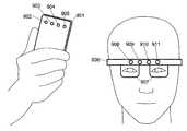
도 9는 본 발명과 관련하여 사용될 수 있는 2개의 예시적인 하드웨어 셋업들을 도시한다. 본 명세서에 설명된 방법은 서모그래픽 카메라(902)가 설치된 스마트폰 또는 태블릿 컴퓨터와 같은 핸드헬드 디바이스(901)(의 일부)에서 수행될 수 있고, 본 명세서에 설명된 디바이스는 그러한 핸드헬드 디바이스(901)(의 일부)일 수 있다. 디바이스는 적어도 하나의 가시광 카메라(903), 적외선 카메라(904), 및/또는 적외선 또는 가시광 프로젝터(905)를 추가로 포함할 수 있다. 다른 실시예에 따르면, 본 명세서에서 설명된 본 방법은 적어도 하나의 디스플레이(907) 및 열 카메라(908)를 갖는 헤드 마운트 (또는 웨어러블) 컴퓨터(906)(의 일부)에서 수행될 수 있고, 본 명세서에 설명된 디바이스는 그러한 헤드 마운트 (또는 웨어러블) 컴퓨터(906)(의 일부)일 수 있다. 디바이스는 적어도 하나의 가시광 카메라(909), 적외선 카메라(910), 및/또는 적외선 또는 가시광 프로젝터(911)를 추가로 포함할 수 있다.
한 번에 발생하는 하나 초과의 터치를 검출하기 위하여 본 명세서에서 설명된 본 방법 및 디바이스를 적용하는 것이 또한 가능하다.
전술된 실시예는 적외선 열 카메라 이미지의 좌표계에서의 터치의 위치(즉, 점)를 제공할 수 있다. 이는 터치된 표면에 대응하는 이미지 내의 영역을 추가로 제공할 수 있다. 영역이 원형이지(원형에 가깝지) 않은 경우, 본 발명은, 예컨대 터치 영역의 가장 큰 크기를 갖는 배향으로서, 터치의 하나 이상의 배향을 추가로 결정할 수 있다. 다른 실시예는 터치의 궤적을 결정한다. 추가 실시예는 터치의 방향을, 즉 궤적 상의 점들이 어떤 순서로 터치되었는지를 추가로 결정한다.
하나 이상의 터치 및 본 발명의 실시예에 의해 결정된 그의 궤적은 (다수의) 터치 제스처들, 예컨대, 스와이프(swipe), 핀치(pinch), 줌을 위한 핀치(pinch-to-zoom), 핀치 클로즈(pinch-close), 핀치 오픈(pinch-open), 회전, 비틀림 회전(twist-rotate), 피벗 회전(pivot-rotate), 스크롤(scroll), 팬(pan), 플릭(flick), 두 손가락 탭(two-finger-tap), 및 두 손가락 스크롤(two-finger-scroll)을 지원하는데 이용될 수 있다.
소정 영역들 내의 터치들의 검출을 피하기 위하여 상이한 수단이 적용될 수 있다. 도 7의 예에서, 가상 버튼들 중 하나에 위치된 터치들만이 유의하다. 따라서, 물체의 표면을 터치들이 검출되어야 하는 일부들 및 터치들이 검출되지 않아야 하거나 검출 후에 무시되어야 하는 일부들로 나누는 마스크가 제공될 수 있다. 한 가지 가능한 구현은 이러한 마스크를 적외선 열 이미지의 프로세싱 전에 도 6의 변환들(608, 607)이 주어진 적외선 열 이미지로 옮기는 것일 것이다.
터치들은 모델이 필요한 실제 물체의 표면 상에 항상 위치되어야 한다. 가시광 카메라가 깊이를 측정할 수 있는 일 실시예에서 또는 추가의 깊이-감지 카메라가 존재하는 경우에, 이는 터치의 3D 위치를 결정하는 데 이용될 수 있다. 물체의 표면 모델까지의 거리가 한계치 초과인 임의의 검출된 터치는 모델 표면 상에 놓여있지 않고 그에 따라서 폐기될 수 있다.
최소한의 인체와는 다른 물체, 예컨대, 소매 단에 의한 의도하지 않은 터치는, 그의 온도가 체온과 상당히 상이한 경우 전술된 실시예에 의해 묵시적으로 무시된다. 다른 실시예는 일련의 적외선 열 카메라 이미지들 및/또는 가시광 카메라 이미지들에서 손을 검출함으로써 검출된 터치가 인간의 손의 적어도 일부의 터치에 의한 것임을 명시적으로 강제한다. 이어서 터치들은 손 검출에 따라 전에 손이 존재하였던 (물체, 또는 카메라의 좌표계에서의) 영역에서 단지 검출될 수 있다. 다른 실시예는 일련의 적외선 열 카메라 이미지들 및/또는 가시광 카메라 이미지들에서 손가락 끝의 위치를 추가로 검출하고, 이어서 손가락 끝 검출에 따라 전에 손가락 끝이 존재하였던 (물체, 또는 카메라의 좌표계에서의) 영역으로 터치 검출을 제한한다.
다른 실시예는 하나 초과의 한계치만큼 체온을 초과하는 온도를 일단 가졌던 모든 영역들을 터치 검출로부터 배제한다. 그러한 온도는 전자 디바이스, 또는 커피 머그잔에 기인할 수 있다.
다양한 실시예들이 소정 구성요소 또는 디바이스를 참조하여 본 명세서에서 설명되었지만, 본 명세서에서 설명되거나 당업자에게 명백한 바와 같은, 구성요소 또는 디바이스의 임의의 다른 구성은, 또한 이들 실시예 중 임의의 것을 구현할 때 사용될 수 있다. 본 명세서에서 설명된 바와 같은 디바이스들 또는 구성요소들 중 임의의 것은 본 명세서에서 설명된 바와 같은 태스크의 전부 또는 일부를 수행하기 위한 각각의 프로세싱 디바이스(명시적으로 도시되지 않음), 예컨대, 마이크로프로세서일 수 있거나, 이를 포함할 수 있다. 프로세싱 태스크들 중 하나 이상은, 예컨대 각각의 지점 대 지점 간 통신에 의해서 또는 네트워크를 통하여, 예컨대 서버 컴퓨터를 통하여, 서로 통신하고 있는 구성요소들 또는 그의 프로세싱 디바이스들 중 하나 이상에 의해 프로세싱될 수 있다.
참조문헌:
[1]FLIR ONE, Personal thermal imaging device for your iPhone5 and iPhone5s,www.flir.com/flirone
[2]http://nae-lab.org/project/thermo-key/ Thermo key
[4]WO 2013/016104 A1
[5]Occlusion based Interaction Methods for Tangible Augmented Reality Environments, Gun A. Lee, Mark Billinghurst, Gerard Jounghyun Kim, VRCAI '04 Proceedings of the 2004 ACM SIGGRAPH international conference on Virtual Reality continuum and its applications in industry, pages 419-426, 2004
[6]WO 2012/039836 A1
[7]WO 2012/040114 Al
[8]US 2011/0050643 A1Now, aspects of the present invention and embodiments will be described with reference to the drawings.
Figure 1 shows a flow diagram of a method according to an embodiment of the invention.
Figure 2 illustrates an example of a thermal image that is mapped to a grayscale for visualization that may be used in connection with the present invention.
Figure 3 illustrates another embodiment of the present invention for determining a touch between two objects based on thermal energy delivered from one object to another by infrared thermography.
Figure 4 shows a thermal image similar to that shown in Figure 2 but discretized and visualized in isoline.
Figure 5 illustrates a series of infrared thermal images in accordance with an embodiment of the present invention.
Figure 6 illustrates an exemplary embodiment of the present invention in which an actual object is imaged by a visible light camera and an infrared thermal camera.
Figure 7 illustrates an embodiment of the present invention that may be used as a human machine interface in an augmented reality application.
Figure 8 illustrates a series of infrared thermal images in which a first object moves over a surface of a second object during a touch, in accordance with an embodiment of the present invention.
Figure 9 illustrates two exemplary hardware setups in the context of the present invention.
While various embodiments are described below with reference to certain elements, any other configuration of elements, as described herein or as will be apparent to those skilled in the art, may also be used when implementing any of these embodiments.
In the following, embodiments and exemplary scenarios will be described, which are not to be construed as limiting the invention.
In an exemplary scenario, a touch between at least a portion of a human body and an object causes thermal energy to be transferred to the object from at least a portion of the human body. This thermal energy then causes emission of radiation in the infrared range. It can be detected using an infrared thermographic camera, and can be used as a human computer interface, in particular for detecting touch events as touch and result triggers.
Figure 1 shows a flow diagram of a method according to an embodiment of the invention. In a
The present invention can distinguish a number of situations. An alternative assumption for this embodiment of the present invention is that the temperature of the actual object is different from the human temperature, which is typically about 36.5 ° C. Only when a part of the human body, for example the fingertip, actually touches the actual surface, it will transfer sufficient heat energy to the real object in the area where the touch occurs, so that the generated radiation emitted by the object in the infrared range It will be clearly measurable by the graphics camera. Alternatively, the present invention can be implemented so that the touch is detected only when the substance touching the real object has a temperature similar to 36.5 캜. Thermographic cameras are available, for example, at low cost anywhere in the present and near future, with reference to reference [1].
Figure 2 shows an example of a thermal image that can be used in connection with the present invention. In particular, Figure 2 shows a hand through a thermal image. The hand can be distinguished from the background clearly because it has a higher temperature. When the fingertip touches the
As described above, an infrared thermographic image allows the detection of a touch by the user to any and unmodified real objects, which in turn can be used as a (tangible) user interaction device. An exemplary application of such a method would utilize a visible light camera to enable an augmented reality experience, as shown in Figures 6 and 7, in addition to a thermographic camera.
For example, the user holds the real object in his or her hand, which is localized in the visible light camera image. On this object, there are virtual buttons that were printed as gray areas on the actual object in this example. A thermal image of the same scene shows a warm fingerprint caused by a part of the human body (finger tip) touching an object. This position of the touch can be localized in the thermal camera image. Since the visible light camera is calibrated against the thermal camera and the shape, position and orientation of the actual object is known to the visible light camera, the position of the touch can be converted to the coordinate system of the real object.
Any desired action on the 3D position of this touch event may be performed, e.g., triggering a virtual button located at the location of the touch on the real object. The touch event may then affect an augmented reality application that displays spatially matched and overlaid virtual content on a live image supply of a visible light camera. In the illustrated example, the touch will change the visualization of the button and will also change the state of the virtual object, which is strongly attached to the actual object and represents the virtual display.
The present invention can be used in any augmented reality application that requires more interaction than changing the position and orientation of an actual object or camera. This is particularly useful when the application requires the selection of one or more locations on the surface of the actual object. It can be used for video surveillance, optical sight, or projection AR setup. While the present invention is suitable for handheld AR applications, it is of particular interest for hardware setups that do not include a touch screen interface, such as a head-mounted display or a projector-based AR. This can be used in many different applications, for example, to directly click on an advertisement or an image, to start a video, for example, in all applications based on tracking a print such as a magazine or a book. This can also be used in maintenance applications in which an operator displays a defect by simply touching him with the operator's hand for subsequent inspection during a painting operation on the vehicle. The present invention enables a highly intuitive and tangible way of human machine interaction without the need to modify the actual objects that interact together and without the need to attach hardware to the user's hands.
There are different approaches according to embodiments of the present invention for determining the thermal energy of an object as a result of a touch (i.e., direct contact) with an object having a different temperature.
One approach to enabling the detection of a touch while two objects are still touching each other is based on the measured thermal distribution gradient according to the thermal camera image. While the transition between two objects with different temperatures, which are not touched, is abrupt and thus has a strong gradient, the touch, i.e. the transition near the physical contact between the two objects becomes smoother and less in the larger area It causes a strong gradient. This is further explained with reference to FIG.
A different approach to determining the touch of two objects at different temperatures that can be applied after a touch occurs is to localize clusters or blobs in the thermal image that satisfy certain constraints on size and average temperature. For example, if the temperatures of two objects are roughly known, there is a way to localize the clusters or blobs having a temperature corresponding to the average value of the two known temperatures with a given tolerance. The size of the clusters or blobs that are considered to be attributable to the touch may be limited, for example, to a fixed range of pixels (e.g., the radius must be 5 or more pixels and 50 or fewer pixels). The constraint on the size of the cluster or blob considered in the thermal image is further constrained by the size of the object in the image of the second camera capturing at least a portion of one of the two objects or from the size of the object of one of the objects in the thermal image . This is further illustrated in Fig.
The method according to one embodiment can determine a touch on an object that happens to have a local change in temperature that can be identified as a blob in the thermal image as described above but is not actually a touch. One approach to distinguishing touches from static blobs at a given temperature is to measure multiple samples of a point's temperature over time, as described below.
A third approach for determining the touch of two objects with different temperatures is based on at least two thermal images of at least a portion of at least one of the objects. The assumption of this approach is that most objects - not at contact with other objects at significantly different temperatures - change their temperature very slowly. Under the assumption of a static thermal camera, a single pixel will represent a point in the environment. Taking three samples at an interval of, for example, 0.5 seconds, the measured temperature will be very similar if the environment does not change during that time. When an object having a temperature different from the temperature of the scene travels through the scene, the three samples can have very different temperatures because the samples are not actually measured at the temperature of a single point in the scene but in at least one of the samples Because the samples are instead measured at the temperature of the moving object. Very rapid changes in temperature are usually due to occlusions by objects with different temperatures. When two objects at different temperatures are touched, the area to which they are touched will change their temperature and then converge back to the initial temperature, as in the pre-touch. Thus, in the case of pixels corresponding to a point in the environment in which the touch has recently occurred, it exhibits a slow but distinctly measurable decrease or increase in temperature. A smooth change in temperature can indicate a touch between two objects that have recently occurred at the sampled position. The same concepts described above can also be applied to a moving camera (e.g., there is movement between each of two objects and the camera). In this case, a tracking method may be needed to determine the camera movement for each of the two objects, or to determine the spatial relationship between each of the two objects and the camera. This allows sampling the temperature of the same point on the object at different points in time even if the camera or object has moved.
By way of example, any change in temperature below 1 ° C or 1 ° C / s may be classified as static, and any change in temperature above 8 ° C or 8 ° C / s may be classified as due to overshoot, Any change in temperature between these two values can be classified as potentially a result of the touch. If such a classification is performed for each pixel or for many samples on an object, then spatial clusters (or blobs) of the samples that are potentially classified as the result of the touch can be found. If these clusters satisfy certain constraints, e.g., their minimum size, or average temperature, a touch is considered to be detected.
Any embodiment that determines a touch in response to a change in temperature (i.e., a temperature change) may utilize at least one difference in temperature (e.g., 3 DEG C) or at least one derivative of temperature (e.g., 3 DEG C / s) have. The at least one difference in temperature may be the difference between the temperatures at different locations in the coordinate system of the thermal image or at different locations within the coordinate system of the object (e.g., the second object). The at least one difference in temperature may be the difference between the temperatures measured at different times for the same or different locations (in the coordinate system of the thermal image or in the coordinate system of the object).
At least one derivative of the temperature can be a first order derivative of the temperature with respect to time (e.g., 3 DEG C / s), a first derivative of the temperature with respect to the location in the thermal image (e.g., 3 DEG C per pixel) (E.g., 3 [deg.] C / mm). Similarly, a second order derivative or any higher order derivative can be used. The derivative of the temperature for any order and for any dimension (e.g., time, position) may be determined according to at least one temperature difference. Differences in time or differences in positions may also be required to determine the derivative of the temperature.
Changes in temperature (changes may be for a temperature distribution across a region, or variations may also be for a temperature or positional location over time), or a threshold used during determination of a touch Scales and other parameters may be used, for example, as a histogram representing the distribution of temperatures in a thermal image, a conventional knowledge of the scene (s) or objects (at least a portion thereof), the thermal conductivity of at least some of the objects , Air temperature measured with an (electronic) thermometer, information about the current weather conditions, or as a basis for determining the characteristics of a scene or objects such as thermal conductivity. These parameters can also be learned in a supervised way given to the exemplary touch.
It should be noted that, in the case of non-static cameras and / or non-static scenes or objects, there are approaches for tracking the position and orientation of an object with respect to the camera. These tracking methods may be based on information obtained from a thermal image, or it may use information captured by a thermal camera or a second camera that images at least a portion of an object, or it may be any other mechanical, electromagnetic, acoustical , Or an optical tracking system. This allows sampling the temperature of the same point on the object at different points in time even if the camera or object has moved.
In general, classifying temperature samples by indicating that a touch has occurred may be based on the measured temperature, or the first derivative of the measured temperature over time, or the second derivative of the temperature over time. Which may further be based on a first or second derivative of the temperatures in the camera's coordinate system or in the object's coordinate system. A classification based on any combination of previous measurements is also a preferred embodiment of the present invention. The results of the local classification (e.g., per pixel) may be further processed by, for example, median filtering, average filtering, dilation, erosion, or clustering.
In the following, the present invention and its embodiments will be described with reference to the drawings of FIGS.
Figure 3 illustrates another embodiment of the present invention for determining a touch between two objects based on thermal energy transferred from one object to another by sensing infrared thermography. A thermographed image 301 (left-hand view) comprising a low temperature
The
The embodiment according to Fig. 3 can detect the touch when the touch is actually occurring, for example, by detecting the
In the embodiment according to Fig. 3, at least a part of the second object touching the first object and a part of the second object visible in at least one thermal image are not superimposed. In this case, the infrared thermal image does not image this part because the finger (i.e., the first object) covers at least a portion of the second object that touches the first object. Instead, the determination of the touch in this case may be based on the determination of the touch of at least one of the imaged region of at least one of the different parts of the second object, in particular at least one thermal image adjacent to at least a portion of the first object At least one column (e.g., a finger) of a first object (e.g., a finger) of an area imaged in the thermal image of the first object, e.g., an area adjacent to at least a portion of a first object that touches a second object, It is based on determining the pattern in the image.
Moreover, in the embodiment according to FIG. 3, at least a portion of the second object touching the first object may be (partially) outside the field of view of the (infrared) thermal camera capturing at least one thermal image.
Embodiments of the present invention may utilize the temperature distribution of at least one sample line in the thermal image to determine the touch. The sample lines do not need to be reduced horizontally, as is the case for 304 and 315, but may have any orientation. They can be randomly sampled in the image, or they can be sampled in a uniform distribution, or they can use the result of fingertip tracking as an input and select sample lines so that they cross fingertips and are orthogonal to the finger direction can do.
A decision tree, an ensemble, an ensemble, a bagging, a boosting, a random forest, etc. which are trained with thermal images showing the touch and two objects of different temperatures, Random forest, k-NN, Linear regression, Naive Bayes, Neural network, Logistic regression, Perceptron, or Support vector machine, It is also possible to determine touches based on thermal images using a supervised machine learning technique, such as SVM.
Figure 4 shows a
One possible approach for identifying and localizing a touch from this single thermal image is to use a
The location of the detected touch may be determined by localizing a range of temperature (s) or temperatures within the
In the embodiment according to Fig. 4, at least a part of the second object touching the first object and a part of the second object visible in at least one thermal image overlap. The pattern determination is based on the temperature of at least a portion of the "at least a portion of the second object" touching the first object.
5 shows a series of infrared
In Region A (Chart 506), the temperature is low throughout the series of images because this region captures only the environment. In Region (B) (Chart 507), once the region captures hands instead of the environment, a
For example, a determined value of the temperature change between at least two thermal images can be used to determine the touch. The value of the temperature change is the difference between at least two temperatures measured in the region C of two different thermal images (e.g.,
In another example, a derivative of the temperature between at least two thermal images can be used to determine the touch. The derivative of the temperature can be the first derivative of the temperature with respect to time.
According to one embodiment, more than one change may be calculated. For example, a first change between
There may be no captured thermal image or measured temperature at the moment between capturing the
In the embodiment according to Fig. 5, at least a part of the second object touching the first object and a part of the second object visible in at least one thermal image overlap. The pattern determination is based on the temperature of at least a portion of the "at least a portion of the second object" touching the first object.
6 illustrates an exemplary embodiment of the present invention in which an actual object 601 (in this case a vehicle) is imaged by a visible
A method for identifying and localizing the
In another embodiment, the
Figure 7 illustrates an example of how the aspects of the present invention may be used as a human computer interface in an augmented reality application. It should be noted that any approach for determining a touch as described herein, such as those described with reference to Figures 3-6, may be used. The scene is shown at four different times (t1, t2, t3, t4), arranged in different vertical lines. For each viewpoint, the image captured by the visible light camera is shown in the first horizontal line. The second horizontal line shows the corresponding image captured by the infrared thermal camera, and the last horizontal line shows the augmented reality (AR) view. The AR view can be accomplished, for example, by video stream setup using a mobile device including a visible light camera, an infrared thermal camera, and a display or head mount display. This can furthermore be based on optical set-up or projection AR setup. It should be noted that in this example it is assumed that the images of the visible light camera and the infrared thermal camera are aligned - this can be achieved, for example, by a beam splitter. In this case, the
At the first point in time t1, there is an object located within the visible palm of the
At the second time point t2, the finger touches the actual object. In both the
At the third time point t3, the finger has moved away from the real object, which is evident in both the visible
At some later time point t4, the object is still held in the hand (visible light camera image 714), but the warm spot disappeared from the infrared
It should be noted that in this example the virtual information is exactly hidden by hand. This can be achieved by using a thermo key (Ref. [2]) that uses infrared thermal images to separate the human foreground from the background of the environment. It should also be noted that in this example the actual object has been placed in the hand, but instead it could also be located somewhere in the environment, e.g. on the table. The final configuration would be preferable if you use a handheld device such as a smartphone or tablet PC.
Figure 8 illustrates a series of binarized infrared thermal images 801-808 in which a first object moves over the surface of a second object during a touch, in accordance with an embodiment of the present invention. In
The embodiment may fit the
Other embodiments may further analyze differences or variations in temperatures between different portions of the touch region to determine the direction of the touch, e.g., the dominant temperature gradient direction in the touch region.
When a user touches a surface at a first point of an object, then moves a finger to a second point on the surface of the object, and then moves the finger away from the object, the touch region is divided into a region around the first point, , And the area between these two points where the finger moved on the surface (see 809). Within the touch region (e.g., at
Figure 9 illustrates two exemplary hardware setups that may be used in connection with the present invention. The method described herein may be performed in (part of) a
It is also possible to apply the present method and device described herein to detect more than one touch occurring at a time.
The above-described embodiment can provide the position (i.e., point) of the touch in the coordinate system of the infrared thermal camera image. This can further provide an area in the image corresponding to the touched surface. If the area is circular (not close to a circle), the invention can additionally determine the orientation of one or more of the touches, for example as an orientation with the largest size of the touch area. Another embodiment determines the trajectory of the touch. A further embodiment further determines the direction of the touch, i. E. In which order the points on the locus are touched.
One or more touches and trajectories thereof, as determined by embodiments of the present invention, may be applied to (multiple) touch gestures such as sweeps, pinchs, pinch-to-zoom for zooming, pinch-open, pinch-open, twist-rotate, pivot-rotate, scroll, pan, flick, two-finger-tap, and two-finger-scroll.
Different means can be applied to avoid detection of the touches within certain regions. In the example of FIG. 7, only the touches located in one of the virtual buttons are significant. Thus, a mask may be provided that divides the surface of the object into portions where the tactics should be detected and portions that should not be detected or that should be ignored after detection. One possible implementation would be to move these masks to the given infrared thermal image of
The touches should always be located on the surface of the real object where the model is needed. In one embodiment in which the visible light camera can measure the depth, or in the presence of an additional depth-sensing camera, this can be used to determine the 3D position of the touch. Any detected touch whose distance to the surface model of the object is above the limit is not placed on the model surface and can be discarded accordingly.
An unintentional touch by an object other than a minimal human body, e.g., a retail end, is implicitly ignored by the embodiments described above if its temperature is significantly different from the body temperature. Another embodiment explicitly enforces that a detected touch by detecting a hand in a series of infrared thermal camera images and / or visible light camera images is due to a touch of at least a portion of a human hand. The touches can then only be detected in the area where the hand was previously present (in the object or in the coordinate system of the camera) according to the hand detection. Another embodiment further detects the position of the fingertip in a series of infrared thermal camera images and / or visible light camera images, and then detects the position of the fingertip in front of the object ) Area.
Other embodiments exclude all regions that once had a temperature exceeding body temperature by more than one threshold from touch detection. Such temperature can be attributed to electronic devices, or coffee mugs.
While various embodiments have been described herein with reference to certain elements or devices, any other configuration of elements or devices, as described herein or as will be apparent to those skilled in the art, may also be used to implement any of these embodiments Can be used. Any of the devices or components as described herein may be coupled to a respective processing device (not explicitly shown) for performing all or a portion of the tasks as described herein, , Or may include the same. One or more of the processing tasks may be processed by one or more of the components or their processing devices communicating with each other, e.g., via respective point-to-point communications or via a network, e.g., via a server computer .
Reference literature:
[1] FLIR ONE, Personal thermal imaging device for your iPhone5 and iPhone5s,www.flir.com/flirone
[2]http://nae-lab.org/project/thermo-key/ Thermo key
[4] WO 2013/016104 A1
[5] Occlusion based Interaction Methods for Tangible Augmented Reality Environments, Gun A. Lee, Mark Billinghurst, Gerard Jounghyun Kim, VRCAI '04 Proceedings of the 2004 ACM SIGGRAPH international conference on virtual reality continuum and its applications in industry, pages 419-426 , 2004
[6] WO 2012/039836 A1
[7] WO 2012/040114 Al
[8] US 2011/0050643 A1
Claims (26)
Translated fromKorean상기 제1 물체의 상기 적어도 일부는 상기 제2 물체의 상기 적어도 일부와 상이한 온도를 갖고,
상기 방법은,
상기 제2 물체의 일부분의 하나의 열 이미지(thermal image)를 수신하는 단계;
상기 하나의 열 이미지의 상이한 위치들에 기초하여 온도 측정들(measurements)을 결정하는 단계; 및
상기 하나의 열 이미지와 연관된 상기 온도 측정들의 변이도(variance)가 기준을 만족시킨다고 결정하는 것에 응답하여, 상기 제1 물체의 상기 적어도 일부와 상기 제2 물체의 상기 적어도 일부 사이의 터치가 일어났다고 결정하는 단계
를 포함하는, 방법.A method of detecting a touch between at least a portion of a first object and at least a portion of a second object,
Wherein the at least part of the first object has a temperature different from the at least part of the second object,
The method comprises:
Receiving a thermal image of a portion of the second object;
Determining temperature measurements based on the different positions of the one thermal image; And
Determining that a touch between the at least a portion of the first object and the at least a portion of the second object has occurred in response to determining that the variance of the temperature measurements associated with the one thermal image meets a criterion Step
/ RTI >
가시광 카메라로부터 상기 제2 물체의 상기 일부분의 이미지를 수신하는 단계 - 상기 하나의 열 이미지는 열 카메라로부터 수신됨 -;
상기 가시광 카메라와 상기 열 카메라 사이의 제1 공간 변환을 결정하는 단계;
상기 가시광 카메라와 상기 제2 물체의 상기 일부분 사이의 제2 공간 변환을 결정하는 단계;
상기 제1 공간 변환과 상기 제2 공간 변환에 기초하여, 상기 제2 물체의 상기 일부분의 좌표계와 상기 열 카메라의 좌표계 사이의 제3 공간 변환을 결정하는 단계; 및
상기 제3 공간 변환에 기초하여 상기 제2 물체의 상기 일부분의 상기 좌표계에서의 상기 열 카메라의 위치 및 배향을 결정하는 단계
를 추가로 포함하는 방법.The method according to claim 1,
Receiving an image of the portion of the second object from a visible light camera, the one thermal image being received from a thermal camera;
Determining a first spatial transformation between the visible light camera and the thermal camera;
Determining a second spatial transformation between the visible light camera and the portion of the second object;
Determining a third spatial transformation between the coordinate system of the portion of the second object and the coordinate system of the thermal camera based on the first spatial transformation and the second spatial transformation; And
Determining a position and orientation of the thermal camera in the coordinate system of the portion of the second object based on the third spatial transformation
≪ / RTI >
상기 하나의 열 이미지에서 상기 터치의 위치를 결정하는 단계;
상기 제2 물체의 상기 좌표계에서 상기 하나의 열 이미지의 이미지 평면의 위치 및 배향을 결정하는 단계; 및
광선을 상기 제2 물체의 모델 상에 투사하고, 상기 광선 및 상기 모델 사이의 교차점을 식별함으로써, 상기 제2 물체의 상기 일부분의 상기 좌표계에서의 상기 터치의 위치를 결정하는 단계 - 상기 광선은 상기 제2 물체의 상기 일부분의 상기 좌표계에서의 상기 열 카메라의 원점으로부터 비롯되고, 상기 터치에 대응하는 상기 이미지 평면의 일부분을 통과함(pass through) -
를 추가로 포함하는 방법.19. The method of claim 18,
Determining a position of the touch in the one column image;
Determining a position and orientation of an image plane of the one thermal image in the coordinate system of the second object; And
Determining a position of the touch in the coordinate system of the portion of the second object by projecting a ray of light onto a model of the second object and identifying an intersection between the ray and the model, Said portion of said image plane originating from the origin of said thermal camera in said coordinate system of said portion of said second object passing through said portion of said image plane corresponding to said touch,
≪ / RTI >
상기 하나의 열 이미지의 상이한 위치들에 기초하여 온도 측정들을 결정하도록, 그리고
상기 하나의 열 이미지와 연관된 상기 온도 측정들의 변이도가 기준을 만족시킨다고 결정하는 것에 응답하여, 제1 물체의 적어도 일부와 상기 제2 물체의 적어도 일부 사이의 터치가 일어났다고 결정하도록
프로세서에 의해 실행가능한 소프트웨어 코드 섹션들을 갖는, 컴퓨터 판독가능한 비일시적 저장 매체.To receive one thermal image of a portion of the second object,
Determine temperature measurements based on the different positions of the one thermal image, and
Determining that a touch between at least a portion of the first object and at least a portion of the second object has occurred in response to determining that the variability of the temperature measurements associated with the one thermal image meets a criterion
A computer readable non-volatile storage medium having software code sections executable by a processor.
상기 제1 물체의 상기 적어도 일부는 상기 제2 물체의 상기 적어도 일부와 상이한 온도를 갖고,
상기 디바이스는,
상기 제2 물체의 일부분의 하나의 열 이미지를 수신하고;
상기 하나의 열 이미지의 상이한 위치들에 기초하여 온도 측정들을 결정하고;
상기 하나의 열 이미지와 연관된 상기 온도 측정들의 변이도가 기준을 만족시킨다고 결정하는 것에 응답하여, 상기 제1 물체의 상기 적어도 일부와 상기 제2 물체의 상기 적어도 일부 사이의 터치가 일어났다고 결정
하도록 구성된 프로세싱 디바이스를 포함하는, 디바이스.A device for detecting a touch between at least a portion of a first object and at least a portion of a second object,
Wherein the at least part of the first object has a temperature different from the at least part of the second object,
The device comprising:
Receive one thermal image of a portion of the second object;
Determine temperature measurements based on the different positions of the one thermal image;
Determining that a touch between the at least a portion of the first object and the at least a portion of the second object has occurred in response to determining that the variability of the temperature measurements associated with the one thermal image meets a criterion
And a processing device configured to perform the processing.
Applications Claiming Priority (1)
| Application Number | Priority Date | Filing Date | Title |
|---|---|---|---|
| PCT/EP2014/053017WO2015120913A1 (en) | 2014-02-17 | 2014-02-17 | Method and device for detecting a touch between a first object and a second object |
Publications (2)
| Publication Number | Publication Date |
|---|---|
| KR20170008720A KR20170008720A (en) | 2017-01-24 |
| KR101918829B1true KR101918829B1 (en) | 2018-11-14 |
Family
ID=50190413
Family Applications (1)
| Application Number | Title | Priority Date | Filing Date |
|---|---|---|---|
| KR1020167022433AActiveKR101918829B1 (en) | 2014-02-17 | 2014-02-17 | Method and device for detecting a touch between a first object and a second object |
Country Status (6)
| Country | Link |
|---|---|
| US (4) | US10877605B2 (en) |
| EP (1) | EP3108330B1 (en) |
| KR (1) | KR101918829B1 (en) |
| CN (1) | CN105992988B (en) |
| AU (1) | AU2014382730C1 (en) |
| WO (1) | WO2015120913A1 (en) |
Families Citing this family (65)
| Publication number | Priority date | Publication date | Assignee | Title |
|---|---|---|---|---|
| US11039109B2 (en) | 2011-08-05 | 2021-06-15 | Fox Sports Productions, Llc | System and method for adjusting an image for a vehicle mounted camera |
| JP2014529930A (en) | 2011-08-05 | 2014-11-13 | フォックス スポーツ プロダクションズ,インコーポレイティッド | Selective capture and display of a portion of a native image |
| US9406025B2 (en)* | 2014-06-04 | 2016-08-02 | International Business Machines Corporation | Touch prediction for visual displays |
| CN105320249A (en)* | 2014-06-13 | 2016-02-10 | 广州杰赛科技股份有限公司 | Interactive method for reality enhancement |
| CN105204608A (en)* | 2014-06-13 | 2015-12-30 | 广州杰赛科技股份有限公司 | Interactive device based on thermosensitive augmented reality |
| CN105302282A (en)* | 2014-06-13 | 2016-02-03 | 广州杰赛科技股份有限公司 | Thermo-sensitivity based reality augmentation system |
| US10389992B2 (en)* | 2014-08-05 | 2019-08-20 | Utherverse Digital Inc. | Immersive display and method of operating immersive display for real-world object alert |
| US9501810B2 (en)* | 2014-09-12 | 2016-11-22 | General Electric Company | Creating a virtual environment for touchless interaction |
| WO2016050290A1 (en)* | 2014-10-01 | 2016-04-07 | Metaio Gmbh | Method and system for determining at least one property related to at least part of a real environment |
| US11159854B2 (en) | 2014-12-13 | 2021-10-26 | Fox Sports Productions, Llc | Systems and methods for tracking and tagging objects within a broadcast |
| US11758238B2 (en) | 2014-12-13 | 2023-09-12 | Fox Sports Productions, Llc | Systems and methods for displaying wind characteristics and effects within a broadcast |
| US9933470B2 (en)* | 2015-08-31 | 2018-04-03 | The Boeing Company | Energy spectrum visualization system |
| JP6472363B2 (en)* | 2015-10-16 | 2019-02-20 | キヤノン株式会社 | Measuring device, measuring method, and article manufacturing method |
| US10325134B2 (en) | 2015-11-13 | 2019-06-18 | Fingerprint Cards Ab | Method and system for calibration of an optical fingerprint sensing device |
| US20170140233A1 (en) | 2015-11-13 | 2017-05-18 | Fingerprint Cards Ab | Method and system for calibration of a fingerprint sensing device |
| CN105528109B (en)* | 2015-12-04 | 2019-03-05 | 北京奇虎科技有限公司 | The touch event response method of wearable device and wearable device |
| CN105468285B (en)* | 2015-12-04 | 2019-05-10 | 北京奇虎科技有限公司 | Wearable devices and touch event response methods for wearable devices |
| CN106993152B (en)* | 2016-01-21 | 2019-11-08 | 杭州海康威视数字技术股份有限公司 | Three-dimension monitoring system and its quick deployment method |
| US20170223797A1 (en)* | 2016-01-29 | 2017-08-03 | Philips Lighting Holding B.V. | Touch-based lighting control using thermal imaging |
| CN105678310B (en)* | 2016-02-03 | 2019-08-06 | 北京京东方多媒体科技有限公司 | Infrared thermal image contour extraction method and device |
| WO2017210331A1 (en)* | 2016-06-01 | 2017-12-07 | Carnegie Mellon University | Hybrid depth and infrared image sensing system and method for enhanced touch tracking on ordinary surfaces |
| JP6086461B1 (en) | 2016-09-09 | 2017-03-01 | 株式会社ネットアプリ | Touch panel and touch panel system |
| JP6763434B2 (en)* | 2016-10-27 | 2020-09-30 | 日本電気株式会社 | Information input device and information input method |
| US11086393B2 (en)* | 2016-12-27 | 2021-08-10 | Sony Corporation | Information processing device, information processing method, and computer program |
| FI20175335A1 (en) | 2017-04-11 | 2018-10-12 | Univ Helsinki | Method and system for determining human-object interaction |
| US10684173B2 (en) | 2017-04-26 | 2020-06-16 | Marco Pinter | Interactive artistic presentation system with thermographic imagery |
| US10447946B2 (en) | 2017-04-26 | 2019-10-15 | Marco Pinter | Interactive artistic presentation system with thermographic imagery |
| US11279481B2 (en) | 2017-05-12 | 2022-03-22 | Phirst Technologies, Llc | Systems and methods for tracking, evaluating and determining a response to emergency situations using unmanned airborne vehicles |
| US11288834B2 (en)* | 2017-05-23 | 2022-03-29 | Brainlab Ag | Determining the relative position between a point cloud generating camera and another camera |
| US10565802B2 (en)* | 2017-08-31 | 2020-02-18 | Disney Enterprises, Inc. | Collaborative multi-modal mixed-reality system and methods leveraging reconfigurable tangible user interfaces for the production of immersive, cinematic, and interactive content |
| CN109559370A (en)* | 2017-09-26 | 2019-04-02 | 华为技术有限公司 | A kind of three-dimensional modeling method and device |
| KR101971791B1 (en)* | 2017-09-28 | 2019-04-23 | 한국과학기술원 | System for providing of augmented reality in indoor space using visible light communication and the method thereof |
| CN107945283B (en)* | 2017-12-06 | 2021-05-14 | 河南省水利勘测设计研究有限公司 | Engineering display method based on mobile augmented reality technology and BIM |
| US11113887B2 (en)* | 2018-01-08 | 2021-09-07 | Verizon Patent And Licensing Inc | Generating three-dimensional content from two-dimensional images |
| JP2020008750A (en)* | 2018-07-10 | 2020-01-16 | セイコーエプソン株式会社 | Display device and display processing method |
| US11036284B2 (en) | 2018-09-14 | 2021-06-15 | Apple Inc. | Tracking and drift correction |
| KR102469722B1 (en)* | 2018-09-21 | 2022-11-22 | 삼성전자주식회사 | Display apparatus and control methods thereof |
| US10809910B2 (en)* | 2018-09-28 | 2020-10-20 | Apple Inc. | Remote touch detection enabled by peripheral device |
| US11073898B2 (en)* | 2018-09-28 | 2021-07-27 | Apple Inc. | IMU for touch detection |
| EP3895136A4 (en) | 2018-12-12 | 2022-07-27 | Hewlett-Packard Development Company, L.P. | VISUALIZATION OF OBJECT MANUFACTURING |
| CN111452537B (en)* | 2019-01-22 | 2022-09-20 | 上海巨哥电子科技有限公司 | Display method and device |
| US11287885B1 (en)* | 2019-01-22 | 2022-03-29 | Facebook Technologies, Llc | Apparatus, system, and method for determining the position of wearables donned by users of artificial reality systems |
| US10928889B1 (en) | 2019-01-22 | 2021-02-23 | Facebook Technologies, Llc | Apparatus, system, and method for directional acoustic sensing via wearables donned by users of artificial reality systems |
| US11244146B2 (en)* | 2019-03-05 | 2022-02-08 | Jpmorgan Chase Bank, N.A. | Systems and methods for secure user logins with facial recognition and blockchain |
| CN110069198B (en)* | 2019-03-11 | 2021-01-05 | 清华大学 | A user interaction platform and a method for identifying and displaying user interaction information |
| EP3895063B1 (en)* | 2019-03-11 | 2024-09-11 | Beijing Zhijian MOQI Technology CO., LTD. | Device and method for contactless fingerprint acquisition |
| US11562598B2 (en)* | 2019-03-25 | 2023-01-24 | Microsoft Technology Licensing, Llc | Spatially consistent representation of hand motion |
| US20200311396A1 (en)* | 2019-03-25 | 2020-10-01 | Microsoft Technology Licensing, Llc | Spatially consistent representation of hand motion |
| US10825245B1 (en)* | 2019-06-03 | 2020-11-03 | Bank Of America Corporation | Three dimensional rendering for a mobile device |
| US10802667B1 (en) | 2019-06-03 | 2020-10-13 | Bank Of America Corporation | Tactile response for user interaction with a three dimensional rendering |
| CN111142763B (en)* | 2019-08-14 | 2021-06-25 | 广东小天才科技有限公司 | A method and electronic device for triggering search |
| CN110633027A (en)* | 2019-09-16 | 2019-12-31 | 广东小天才科技有限公司 | A method, system, computer equipment and storage medium for realizing point reading |
| US11379033B2 (en)* | 2019-09-26 | 2022-07-05 | Apple Inc. | Augmented devices |
| US11934584B2 (en) | 2019-09-27 | 2024-03-19 | Apple Inc. | Finger orientation touch detection |
| US11321939B2 (en)* | 2019-11-26 | 2022-05-03 | Microsoft Technology Licensing, Llc | Using machine learning to transform image styles |
| US11270448B2 (en) | 2019-11-26 | 2022-03-08 | Microsoft Technology Licensing, Llc | Using machine learning to selectively overlay image content |
| EP4127874A1 (en)* | 2020-03-31 | 2023-02-08 | Flir Systems AB | Thermal imaging asset inspection systems and methods |
| US11598671B2 (en)* | 2020-06-17 | 2023-03-07 | Microsoft Technology Licensing, Llc | Body temperature estimation via thermal intensity distribution |
| JP2023133635A (en)* | 2020-07-30 | 2023-09-26 | ソニーグループ株式会社 | Information processing apparatus, tactile presentation system, and program |
| US20220100196A1 (en)* | 2020-09-25 | 2022-03-31 | Duke University | Smart Thermal Tracking to Guide Surface Sanitization |
| KR102656079B1 (en)* | 2020-11-23 | 2024-04-09 | 주식회사 엠테이크 | Unit for error correction and object temperature measuring device with the same |
| JP7287407B2 (en)* | 2021-01-29 | 2023-06-06 | いすゞ自動車株式会社 | Contact determination device, contact determination method and program |
| EP4064007A1 (en)* | 2021-03-22 | 2022-09-28 | Koninklijke Philips N.V. | Tactile interaction monitoring |
| EP4068178A1 (en) | 2021-03-30 | 2022-10-05 | Sony Group Corporation | An electronic device and related methods for monitoring objects |
| US20230222822A1 (en)* | 2021-12-30 | 2023-07-13 | Apeel Technology, Inc. | Systems and methods for assessment of food item dryness |
Citations (2)
| Publication number | Priority date | Publication date | Assignee | Title |
|---|---|---|---|---|
| US20120320158A1 (en)* | 2011-06-14 | 2012-12-20 | Microsoft Corporation | Interactive and shared surfaces |
| US20130257751A1 (en)* | 2011-04-19 | 2013-10-03 | Sony Computer Entertainment Inc. | Detection of interaction with virtual object from finger color change |
Family Cites Families (27)
| Publication number | Priority date | Publication date | Assignee | Title |
|---|---|---|---|---|
| US5644687A (en)* | 1994-12-29 | 1997-07-01 | International Business Machines Corporation | Methods and system for thermal analysis of electronic packages |
| JP3834766B2 (en)* | 2000-04-03 | 2006-10-18 | 独立行政法人科学技術振興機構 | Man machine interface system |
| JP3903968B2 (en)* | 2003-07-30 | 2007-04-11 | 日産自動車株式会社 | Non-contact information input device |
| US7519210B2 (en)* | 2004-09-09 | 2009-04-14 | Raphael Hirsch | Method of assessing localized shape and temperature of the human body |
| WO2006109476A1 (en)* | 2005-04-05 | 2006-10-19 | Nissan Motor Co., Ltd. | Command input system |
| CN102027439A (en)* | 2008-05-12 | 2011-04-20 | 夏普株式会社 | Display device and control method |
| CN201383133Y (en)* | 2008-12-09 | 2010-01-13 | 上海纽发利商贸有限公司 | Photo-induction touch panel device |
| US8306265B2 (en)* | 2009-01-12 | 2012-11-06 | Eastman Kodak Company | Detection of animate or inanimate objects |
| CN102004544B (en) | 2009-08-28 | 2016-04-13 | 英华达(上海)电子有限公司 | The electronic installation of user interface control method and use the method |
| US8786698B2 (en)* | 2010-09-23 | 2014-07-22 | Sony Computer Entertainment Inc. | Blow tracking user interface system and method |
| US8638364B2 (en) | 2010-09-23 | 2014-01-28 | Sony Computer Entertainment Inc. | User interface system and method using thermal imaging |
| JP5617581B2 (en)* | 2010-12-08 | 2014-11-05 | オムロン株式会社 | Gesture recognition device, gesture recognition method, control program, and recording medium |
| US9176990B2 (en)* | 2011-03-04 | 2015-11-03 | Fluke Corporation | Visual image annotation, tagging of infrared images, and infrared image linking |
| US9785242B2 (en)* | 2011-03-12 | 2017-10-10 | Uday Parshionikar | Multipurpose controllers and methods |
| CN102693042A (en)* | 2011-03-22 | 2012-09-26 | 中兴通讯股份有限公司 | Imaging keyboard generation method and apparatus |
| US10007330B2 (en)* | 2011-06-21 | 2018-06-26 | Microsoft Technology Licensing, Llc | Region of interest segmentation |
| US20120327218A1 (en)* | 2011-06-21 | 2012-12-27 | Microsoft Corporation | Resource conservation based on a region of interest |
| US20130022274A1 (en) | 2011-07-22 | 2013-01-24 | Qualcomm Incorporated | Specifying values by occluding a pattern on a target |
| US8275413B1 (en) | 2011-09-17 | 2012-09-25 | Fraden Corp. | Wireless communication device with integrated electromagnetic radiation sensors |
| CN103017909A (en)* | 2011-09-28 | 2013-04-03 | 李碧洲 | Device and method for measuring temperature and mobile communication equipment equipped with device |
| US8891820B2 (en)* | 2011-09-29 | 2014-11-18 | The Boeing Company | Multi-modal sensor fusion |
| JP2013080413A (en)* | 2011-10-05 | 2013-05-02 | Sony Corp | Input apparatus and input recognition method |
| US10101810B2 (en)* | 2011-11-28 | 2018-10-16 | At&T Intellectual Property I, L.P. | Device feedback and input via heating and cooling |
| US10209881B2 (en)* | 2012-03-15 | 2019-02-19 | Ibrahim Farid Cherradi El Fadili | Extending the free fingers typing technology and introducing the finger taps language technology |
| TWI479362B (en)* | 2012-09-19 | 2015-04-01 | Wistron Corp | Dual-mode remote control method |
| US20140201685A1 (en)* | 2013-01-14 | 2014-07-17 | Darren Lim | User input determination |
| US10254844B2 (en)* | 2013-06-20 | 2019-04-09 | Uday Parshionikar | Systems, methods, apparatuses, computer readable medium for controlling electronic devices |
- 2014
- 2014-02-17WOPCT/EP2014/053017patent/WO2015120913A1/enactiveApplication Filing
- 2014-02-17EPEP14707346.4Apatent/EP3108330B1/enactiveActive
- 2014-02-17CNCN201480075688.8Apatent/CN105992988B/enactiveActive
- 2014-02-17KRKR1020167022433Apatent/KR101918829B1/enactiveActive
- 2014-02-17AUAU2014382730Apatent/AU2014382730C1/enactiveActive
- 2014-03-24USUS14/223,601patent/US10877605B2/enactiveActive
- 2016
- 2016-09-23USUS15/274,968patent/US10719170B2/enactiveActive
- 2020
- 2020-12-23USUS17/133,043patent/US11797132B2/enactiveActive
- 2023
- 2023-09-07USUS18/462,912patent/US20240061532A1/enactivePending
Patent Citations (2)
| Publication number | Priority date | Publication date | Assignee | Title |
|---|---|---|---|---|
| US20130257751A1 (en)* | 2011-04-19 | 2013-10-03 | Sony Computer Entertainment Inc. | Detection of interaction with virtual object from finger color change |
| US20120320158A1 (en)* | 2011-06-14 | 2012-12-20 | Microsoft Corporation | Interactive and shared surfaces |
Also Published As
| Publication number | Publication date |
|---|---|
| EP3108330A1 (en) | 2016-12-28 |
| WO2015120913A1 (en) | 2015-08-20 |
| AU2014382730C1 (en) | 2018-03-22 |
| CN105992988B (en) | 2019-12-17 |
| US20210117042A1 (en) | 2021-04-22 |
| US20150234454A1 (en) | 2015-08-20 |
| US11797132B2 (en) | 2023-10-24 |
| US20240061532A1 (en) | 2024-02-22 |
| EP3108330B1 (en) | 2021-10-20 |
| US20170075502A1 (en) | 2017-03-16 |
| CN105992988A (en) | 2016-10-05 |
| AU2014382730A1 (en) | 2016-09-01 |
| AU2014382730B2 (en) | 2017-09-14 |
| US10719170B2 (en) | 2020-07-21 |
| KR20170008720A (en) | 2017-01-24 |
| US10877605B2 (en) | 2020-12-29 |
Similar Documents
| Publication | Publication Date | Title |
|---|---|---|
| KR101918829B1 (en) | Method and device for detecting a touch between a first object and a second object | |
| EP2907004B1 (en) | Touchless input for a user interface | |
| JP6360050B2 (en) | Method and system for simultaneous human-computer gesture-based interaction using unique noteworthy points on the hand | |
| US8837780B2 (en) | Gesture based human interfaces | |
| US9122311B2 (en) | Visual feedback for tactile and non-tactile user interfaces | |
| KR102335132B1 (en) | Multi-modal gesture based interactive system and method using one single sensing system | |
| US8933882B2 (en) | User centric interface for interaction with visual display that recognizes user intentions | |
| Caputo et al. | 3D hand gesture recognition based on sensor fusion of commodity hardware | |
| CN107422949A (en) | Projection touch image selection method | |
| KR102347248B1 (en) | Method and apparatus for recognizing touch gesture | |
| TWI486815B (en) | Display device, system and method for controlling the display device | |
| US11501459B2 (en) | Information processing apparatus, method of information processing, and information processing system | |
| US20120176341A1 (en) | Method and apparatus for camera projector system for enabling an interactive surface | |
| GB2524247A (en) | Control of data processing | |
| Abdelrahman | Thermal imaging for interactive surfaces | |
| CN116204060A (en) | Gesture-based movement and manipulation of the mouse pointer | |
| TWM486800U (en) | Variable angle double purpose body sensor capable of detecting image |
Legal Events
| Date | Code | Title | Description |
|---|---|---|---|
| A201 | Request for examination | ||
| PA0105 | International application | Patent event date:20160817 Patent event code:PA01051R01D Comment text:International Patent Application | |
| PA0201 | Request for examination | Patent event code:PA02012R01D Patent event date:20160817 Comment text:Request for Examination of Application | |
| PG1501 | Laying open of application | ||
| E902 | Notification of reason for refusal | ||
| PE0902 | Notice of grounds for rejection | Comment text:Notification of reason for refusal Patent event date:20180115 Patent event code:PE09021S01D | |
| PN2301 | Change of applicant | Patent event date:20180611 Comment text:Notification of Change of Applicant Patent event code:PN23011R01D | |
| E701 | Decision to grant or registration of patent right | ||
| PE0701 | Decision of registration | Patent event code:PE07011S01D Comment text:Decision to Grant Registration Patent event date:20180810 | |
| GRNT | Written decision to grant | ||
| PR0701 | Registration of establishment | Comment text:Registration of Establishment Patent event date:20181108 Patent event code:PR07011E01D | |
| PR1002 | Payment of registration fee | Payment date:20181108 End annual number:3 Start annual number:1 | |
| PG1601 | Publication of registration | ||
| PR1001 | Payment of annual fee | Payment date:20211015 Start annual number:4 End annual number:4 | |
| PR1001 | Payment of annual fee | Payment date:20220929 Start annual number:5 End annual number:5 | |
| PR1001 | Payment of annual fee | Payment date:20231004 Start annual number:6 End annual number:6 | |
| PR1001 | Payment of annual fee | Payment date:20240927 Start annual number:7 End annual number:7 |