KR101917681B1 - Mobile terminal and method of fabricating case thereof - Google Patents
Mobile terminal and method of fabricating case thereofDownload PDFInfo
- Publication number
- KR101917681B1 KR101917681B1KR1020110091447AKR20110091447AKR101917681B1KR 101917681 B1KR101917681 B1KR 101917681B1KR 1020110091447 AKR1020110091447 AKR 1020110091447AKR 20110091447 AKR20110091447 AKR 20110091447AKR 101917681 B1KR101917681 B1KR 101917681B1
- Authority
- KR
- South Korea
- Prior art keywords
- pieces
- frame
- case
- mobile terminal
- disposed
- Prior art date
- Legal status (The legal status is an assumption and is not a legal conclusion. Google has not performed a legal analysis and makes no representation as to the accuracy of the status listed.)
- Expired - Fee Related
Links
Images


Classifications
- H—ELECTRICITY
- H04—ELECTRIC COMMUNICATION TECHNIQUE
- H04M—TELEPHONIC COMMUNICATION
- H04M1/00—Substation equipment, e.g. for use by subscribers
- H04M1/02—Constructional features of telephone sets
- H04M1/0202—Portable telephone sets, e.g. cordless phones, mobile phones or bar type handsets
- H04M1/0279—Improving the user comfort or ergonomics
- H04M1/0283—Improving the user comfort or ergonomics for providing a decorative aspect, e.g. customization of casings, exchangeable faceplate
- G—PHYSICS
- G06—COMPUTING OR CALCULATING; COUNTING
- G06F—ELECTRIC DIGITAL DATA PROCESSING
- G06F1/00—Details not covered by groups G06F3/00 - G06F13/00 and G06F21/00
- G06F1/16—Constructional details or arrangements
- G06F1/1613—Constructional details or arrangements for portable computers
- G06F1/1633—Constructional details or arrangements of portable computers not specific to the type of enclosures covered by groups G06F1/1615 - G06F1/1626
- G06F1/1656—Details related to functional adaptations of the enclosure, e.g. to provide protection against EMI, shock, water, or to host detachable peripherals like a mouse or removable expansions units like PCMCIA cards, or to provide access to internal components for maintenance or to removable storage supports like CDs or DVDs, or to mechanically mount accessories
- H—ELECTRICITY
- H04—ELECTRIC COMMUNICATION TECHNIQUE
- H04B—TRANSMISSION
- H04B1/00—Details of transmission systems, not covered by a single one of groups H04B3/00 - H04B13/00; Details of transmission systems not characterised by the medium used for transmission
- H04B1/38—Transceivers, i.e. devices in which transmitter and receiver form a structural unit and in which at least one part is used for functions of transmitting and receiving
- H04B1/3827—Portable transceivers
- H04B1/3833—Hand-held transceivers
- H—ELECTRICITY
- H05—ELECTRIC TECHNIQUES NOT OTHERWISE PROVIDED FOR
- H05K—PRINTED CIRCUITS; CASINGS OR CONSTRUCTIONAL DETAILS OF ELECTRIC APPARATUS; MANUFACTURE OF ASSEMBLAGES OF ELECTRICAL COMPONENTS
- H05K5/00—Casings, cabinets or drawers for electric apparatus
- H05K5/02—Details
- H05K5/0217—Mechanical details of casings
- H05K5/0243—Mechanical details of casings for decorative purposes
- Y—GENERAL TAGGING OF NEW TECHNOLOGICAL DEVELOPMENTS; GENERAL TAGGING OF CROSS-SECTIONAL TECHNOLOGIES SPANNING OVER SEVERAL SECTIONS OF THE IPC; TECHNICAL SUBJECTS COVERED BY FORMER USPC CROSS-REFERENCE ART COLLECTIONS [XRACs] AND DIGESTS
- Y10—TECHNICAL SUBJECTS COVERED BY FORMER USPC
- Y10T—TECHNICAL SUBJECTS COVERED BY FORMER US CLASSIFICATION
- Y10T24/00—Buckles, buttons, clasps, etc.
- Y10T24/45—Separable-fastener or required component thereof [e.g., projection and cavity to complete interlock]
- Y10T24/45225—Separable-fastener or required component thereof [e.g., projection and cavity to complete interlock] including member having distinct formations and mating member selectively interlocking therewith
- Y10T24/45241—Slot and tab or tongue
Landscapes
- Engineering & Computer Science (AREA)
- Computer Hardware Design (AREA)
- General Engineering & Computer Science (AREA)
- Theoretical Computer Science (AREA)
- Signal Processing (AREA)
- Human Computer Interaction (AREA)
- Physics & Mathematics (AREA)
- General Physics & Mathematics (AREA)
- Microelectronics & Electronic Packaging (AREA)
- Computer Networks & Wireless Communication (AREA)
- Telephone Set Structure (AREA)
Abstract
Translated fromKoreanDescription
Translated fromKorean본 발명은 케이스를 구비하는 이동 단말기 및 이동 단말기의 케이스 제조 방법에 관한 것이다.The present invention relates to a mobile terminal having a case and a case manufacturing method of the mobile terminal.
이동 단말기는 휴대가 가능하면서 음성 및 영상 통화 기능, 정보를 입·출력하는 기능 및 데이터를 저장할 수 있는 기능 등을 하나 이상 갖춘 휴대용 전자기기이다.A mobile terminal is a portable electronic device that is portable and has one or more functions of voice and video call function, information input / output function, and data storing function.
이동 단말기는 기능이 다양화됨에 따라 예를 들어, 사진이나 동영상의 촬영, 음악이나 동영상 파일의 재생, 게임 및 방송의 수신 등의 복잡한 기능들을 갖춘 멀티미디어 기기(Multimedia Player) 형태로 구현되고 있다.As the functions of the mobile terminal are diversified, the mobile terminal is implemented in the form of a multimedia device having complicated functions such as photographing and photographing of a moving picture, reproduction of a music or video file, and reception of a game and a broadcast.
멀티 미디어 기기의 복잡한 기능을 구현하기 위해 하드웨어 또는 소프트웨어의 면에서 새로운 다양한 시도들이 적용되고 있다.Various new attempts have been made in terms of hardware or software to implement the complex functions of multimedia devices.
이동 단말기는 자신의 개성을 표현하기 위한 개인 휴대품으로 여겨지면서, 다양한 디자인적 형태가 요구되고 있다. 디자인적 형태는 이동 단말기의 외관을 개선하는 구조적인 변화 및 개량을 포함한다.Mobile terminals are regarded as personal items for expressing their individuality, and various design forms are required. The design form includes structural changes and improvements that improve the appearance of the mobile terminal.
이동 단말기는 외관을 구성하는 케이스를 구비한다. 케이스는 이동 단말기를 주변 환경으로부터 보호하는 단순한 기능을 넘어 심미적인 기능을 갖는다. 상기 구조적인 변화 및 개량의 일 예로 케이스에 다양한 패턴을 구현할 수 있는 이동 단말기가 고려될 수 있다.The mobile terminal has a case constituting an appearance. The case has an aesthetic function beyond a simple function of protecting the mobile terminal from the surrounding environment. As an example of the structural change and improvement, a mobile terminal capable of implementing various patterns in a case can be considered.
본 발명은 케이스에 다양한 패턴이 구현된 이동 단말기 및 상기 케이스의 제조 방법을 제시하기 위한 것이다.The present invention is to provide a mobile terminal in which various patterns are implemented in a case and a method of manufacturing the case.
이와 같은 본 발명의 해결 과제를 달성하기 위하여, 본 발명의 일 실시예에 따르는 이동 단말기는 단말기의 외관을 이루는 케이스를 구비하며, 상기 케이스는 지르코니아(zirconia) 또는 세라믹(ceramic)으로 형성되고 각각이 기설정된 형상으로 이루어지는 복수의 피스(piece), 및 상기 복수의 피스를 수용하도록 일면에서 리세스되게(recessed) 형성되며 상기 복수의 피스의 테두리를 덮도록 배치되는 프레임을 포함하고, 상기 복수의 피스는 각각이 반복적으로 배치되어 상기 케이스의 일면을 형성한다.According to an aspect of the present invention, there is provided a mobile terminal including a casing forming an outer appearance of a mobile terminal, the casing being formed of zirconia or ceramic, A plurality of pieces of a predetermined shape and a frame which is recessed in one surface to receive the plurality of pieces and is arranged to cover the rim of the plurality of pieces, Are each repeatedly arranged to form one surface of the case.
본 발명과 관련된 일 예에 따르면, 상기 복수의 피스 각각은 외부로 드러나는 노출부, 및 인접한 피스의 상기 노출부에 의해 덮이도록 이루어지는 중첩부를 포함한다. 상기 노출부와 상기 중첩부는 서로 단차지게 형성될 수 있다. 또한, 상기 복수의 피스 중 어느 하나에 형성되는 상기 노출부는 다른 하나에 형성되는 상기 노출부와 동일 평면을 형성할 수 있다.According to one example related to the present invention, each of the plurality of pieces includes an exposed portion exposed to the outside, and an overlapped portion made to be covered by the exposed portion of the adjacent piece. The exposed portion and the overlapped portion may be formed to be stepped on each other. In addition, the exposed portion formed on any one of the plurality of pieces may form the same plane as the exposed portion formed on the other.
본 발명과 관련된 다른 일 예에 따르면, 상기 복수의 피스 각각은 상면과 하면을 구비하는 바디와, 상기 상면으로부터 연장되고 상기 상면과 함께 외부로 드러나는 제1연장부, 및 상기 하면으로부터 연장되며 인접한 피스의 상기 제1연장부에 의해 덮이도록 이루어지는 제2연장부를 포함한다. 상기 복수의 피스 중 어느 하나의 제1연장부 및 상기 제1연장부와 중첩되는 다른 하나의 제2연장부 사이에는 상기 복수의 피스가 소결되어 상기 제1연장부와 상기 제2연장부를 결합하는 결합층이 형성될 수 있다.According to another embodiment of the present invention, each of the plurality of pieces includes a body having an upper surface and a lower surface, a first extension extending from the upper surface and exposed to the outside together with the upper surface, And the second extension portion is configured to be covered by the first extension portion of the second extension portion. The plurality of pieces are sintered between any one of the first extending portions and the second extending portions overlapping the first extending portions to sinter the first extending portions and the second extending portions A bonding layer can be formed.
본 발명과 관련된 다른 일 예에 따르면, 상기 복수의 피스 각각은 적어도 일면이 외부로 드러나고 수용홈을 구비하는 베이스, 및 인접한 피스의 상기 수용홈에 삽입되도록 상기 베이스에서 돌출되게 형성되며 상기 인접한 피스와 중첩되게 배치되는 돌출부를 포함한다. 상기 수용홈에는 상기 돌출부의 이탈을 제한하는 걸림홈이 형성될 수 있다. 또한, 상기 이동 단말기는 가장자리에 배치되는 피스에 결합되는 마감부재를 더 포함할 수 있다. 상기 마감부재에는 걸림후크가 형성될 수 있고, 상기 프레임에는 상기 복수의 피스와 결합된 상기 마감부재가 프레임에 고정될 수 있도록 상기 걸림후크와 체결되는 걸림홈이 형성될 수 있다.According to another embodiment of the present invention, each of the plurality of pieces includes a base having at least one surface exposed to the outside and having a receiving groove, and a base portion protruding from the base to be inserted into the receiving groove of the adjacent piece, And includes projections which are arranged to overlap with each other. The receiving groove may be formed with a latching groove for limiting the release of the protrusion. The mobile terminal may further include a finishing member coupled to the piece disposed at the edge. The closure hook may be formed on the closure member, and the frame may be formed with a locking groove to be coupled with the closure hook so that the closure member coupled to the plurality of pieces can be fixed to the frame.
본 발명과 관련된 다른 일 예에 따르면, 상기 복수의 피스의 바닥면에는 가이드홈이 각각 형성되고, 상기 프레임에는 상기 복수의 피스가 기설정된 위치에 각각 장착될 수 있도록 상기 가이드홈에 삽입되는 가이드리브가 형성된다. 상기 가이드홈은 상기 복수의 피스 각각에 제1방향으로 연장되게 형성되는 제1홈 및 상기 제1방향에 대해 교차하는 제2방향으로 연장되게 형성되는 제2홈을 구비할 수 있다.According to another embodiment of the present invention, a guide groove is formed on a bottom surface of each of the plurality of pieces, and a guide rib which is inserted into the guide groove such that the plurality of pieces can be respectively installed at predetermined positions . The guide groove may have a first groove formed in each of the plurality of pieces so as to extend in a first direction and a second groove formed in a second direction extending in a second direction intersecting the first direction.
본 발명과 관련된 다른 일 예에 따르면, 상기 이동 단말기는 상기 복수의 피스를 덮도록 배치되는 커버층을 더 포함한다.According to another embodiment of the present invention, the mobile terminal further includes a cover layer disposed to cover the plurality of pieces.
본 발명과 관련된 다른 일 예에 따르면, 상기 이동 단말기는 합성수지로 형성되고, 상기 복수의 피스의 하단부를 각각 덮도록 이루어지며, 상기 프레임에 장착되는 베이스를 더 포함한다. 상기 복수의 피스는 인서트 사출을 통해 상기 베이스에 결합될 수 있다. 상기 프레임에는 관통홀이 형성될 수 있고, 상기 베이스에는 일면에서 돌출되어 상기 관통홀에 삽입되는 폴(pole)이 형성될 수 있다. 또한, 상기 관통홀을 통해 노출되는 상기 폴의 단부는 융착되어 융착부를 형성할 수 있다.According to another embodiment of the present invention, the mobile terminal further includes a base, which is formed of synthetic resin and covers the lower ends of the plurality of pieces, respectively, and is mounted to the frame. The plurality of pieces may be coupled to the base through insert injection. A through hole may be formed in the frame, and a pole protruding from one surface of the base may be formed to be inserted into the through hole. The ends of the pawls exposed through the through holes may be fused to form a fused portion.
본 발명과 관련된 다른 일 예에 따르면, 상기 이동 단말기는 상기 복수의 피스와 상기 프레임 사이에 배치되는 접착시트, 및 합성수지로 형성되고 인서트 사출을 통해 상기 복수의 피스의 하단부와 상기 프레임을 각각 덮도록 이루어지는 베이스를 더 포함한다. 상기 접착시트는 기설정된 온도 이상에서 접착성을 갖도록 형성되며, 인서트 사출시 발생되는 열을 통해 상기 복수의 피스 각각을 상기 프레임에 결합하도록 이루어질 수 있다.According to another embodiment of the present invention, the mobile terminal includes an adhesive sheet disposed between the plurality of pieces and the frame, and an adhesive sheet formed of synthetic resin and covering the lower ends of the plurality of pieces and the frame through an insert injection, respectively. As shown in Fig. The adhesive sheet is formed to have adhesiveness at a predetermined temperature or higher, and may be configured to couple each of the plurality of pieces to the frame through heat generated when the insert is injected.
또한 상기한 과제를 실현하기 위하여 본 발명은, 단말기의 외관을 이루는 케이스의 제조 방법에 있어서, 사출 성형(injection molding) 또는 압축 성형(compression molding)을 통해 지르코니아(zirconia) 또는 세라믹(ceramic)으로 형성되는 복수의 피스(piece)를 제작하는 단계와, 어느 하나의 피스의 돌출부를 다른 하나의 피스의 수용홈에 끼워 상기 복수의 피스를 반복적으로 배치하는 단계와, 가장자리에 배치되는 피스에 테두리를 마감하는 마감부재를 결합하는 단계, 및 상기 복수의 피스와 상기 마감부재를 프레임에 결합하는 단계를 포함하는 이동 단말기의 케이스 제조 방법을 제시한다.According to another aspect of the present invention, there is provided a method of manufacturing a case which forms an appearance of a terminal, the method comprising the steps of: forming the body by zirconia or ceramic through injection molding or compression molding; A step of repeatedly arranging the plurality of pieces by inserting protrusions of one of the pieces into the receiving grooves of the other piece; finishing the edges of the pieces arranged at the edges; And joining the plurality of pieces and the closure member to the frame.
상기와 같은 구성의 본 발명에 의하면, 지르코니아 또는 세라믹으로 형성되는 복수의 피스가 반복적으로 배치되어 케이스의 일면을 형성함으로써, 상기 소재로 보다 넓은 면적 및 얇은 두께를 갖는 케이스가 구현될 수 있다.According to the present invention, a plurality of pieces made of zirconia or ceramics are repeatedly arranged to form one side of the case, so that a case having a larger area and a thin thickness can be realized as the material.
복수의 피스가 서로 중첩되게 배치되어 연결됨으로써, 단일 제품 대비 성형/소결 과정에서의 뒤틀림, 깨짐 등의 변형 및 파손이 최소화될 수 있는바 제품의 수율이 향상될 수 있다. 또한, 상기 연결 구조를 통해 금형 자체에서 구현하기 어려운 입체 형상을 구현할 수 있다.Since the plurality of pieces are arranged so as to be overlapped with each other, deformation and breakage such as twisting and breaking in the molding / sintering process compared to a single product can be minimized, and the yield of the product can be improved. In addition, a three-dimensional shape that is difficult to be realized in the mold itself can be realized through the connection structure.
아울러, 소재 자체가 주는 고급감 및 다양한 패턴화를 통해 케이스에 심미감을 더해줄 수 있으며, 소재가 갖는 높은 경도에 따른 케이스의 스크래치 방지 효과를 얻을 수 있다.In addition, a sense of beauty can be added to the case through the high quality and various patterning of the material itself, and the scratch prevention effect of the case according to the high hardness of the material can be obtained.
도 1은 본 발명의 일 실시예와 관련된 이동 단말기의 블록 구성도(block diagram).
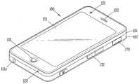
도 2는 본 발명과 관련된 이동 단말기의 일 예를 전면에서 바라본 사시도.
도 3은 도 2에 도시된 이동 단말기의 후면 사시도.
도 4는 도 3의 리어 케이스의 일 예를 보인 개념도.
도 5는 도 3에 도시된 라인 Ⅴ-Ⅴ를 따라 취한 단면도.
도 6 및 7은 도 3의 리어 케이스 구조의 변형예와 이의 제조 방법을 보인 개념도들.
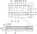
도 8은 도 3의 리어 케이스 구조의 변형예로서, 복수의 피스가 중첩된 구조를 보인 개념도.
도 9는 도 8에 도시된 리어 케이스를 측면에서 바라본 단면도.
도 10은 도 3의 리어 케이스 구조의 변형예로서, 복수의 피스가 중첩된 구조를 보인 개념도.
도 11은 도 10에 도시된 리어 케이스를 측면에서 바라본 단면도.1 is a block diagram of a mobile terminal according to an embodiment of the present invention.
FIG. 2 is a perspective view of an example of a mobile terminal according to the present invention. FIG.
3 is a rear perspective view of the mobile terminal shown in FIG. 2;
4 is a conceptual view showing an example of the rear case of FIG. 3;
5 is a cross-sectional view taken along line V-V shown in Fig. 3; Fig.
Figs. 6 and 7 are conceptual views showing a modification of the rear case structure of Fig. 3 and a method of manufacturing the same.
Fig. 8 is a modification of the rear case structure of Fig. 3, which is a conceptual view showing a structure in which a plurality of pieces are superimposed. Fig.
Fig. 9 is a sectional view of the rear case shown in Fig. 8 when viewed from the side; Fig.
Fig. 10 is a modification of the rear case structure of Fig. 3, and is a conceptual view showing a structure in which a plurality of pieces are superimposed. Fig.
FIG. 11 is a sectional view of the rear case shown in FIG. 10 as viewed from the side; FIG.
이하, 본 발명과 관련된 이동 단말기 및 이의 케이스 제조 방법에 대하여 도면을 참조하여 보다 상세하게 설명한다.Hereinafter, a mobile terminal and a method of manufacturing the case according to the present invention will be described in detail with reference to the drawings.
본 명세서에서는 서로 다른 실시예라도 동일·유사한 구성에 대해서는 동일·유사한 참조번호를 부여하고, 그 설명은 처음 설명으로 갈음한다. 본 명세서에서 사용되는 단수의 표현은 문맥상 명백하게 다르게 뜻하지 않는 한 복수의 표현을 포함한다.In the present specification, the same or similar reference numerals are given to different embodiments in the same or similar configurations. As used herein, the singular forms "a", "an" and "the" include plural referents unless the context clearly dictates otherwise.
이하의 설명에서 사용되는 구성요소에 대한 접미사 "모듈" 및 "부"는 명세서 작성의 용이함만이 고려되어 부여되거나 혼용되는 것으로서, 그 자체로 서로 구별되는 의미 또는 역할을 갖는 것은 아니다.The suffix "module" and " part "for the components used in the following description are given or mixed in consideration of ease of specification, and do not have their own meaning or role.
본 명세서에서 설명되는 이동 단말기에는 휴대폰, 스마트 폰(smart phone), 노트북 컴퓨터(laptop computer), 디지털방송용 단말기, PDA(Personal Digital Assistants), PMP(Portable Multimedia Player), 전자책(E-book), 네비게이션 등이 포함될 수 있다.The mobile terminal described in this specification includes a mobile phone, a smart phone, a laptop computer, a digital broadcasting terminal, a PDA (Personal Digital Assistants), a PMP (Portable Multimedia Player), an e-book, Navigation, and the like.
도 1은 본 발명의 일 실시예와 관련된 이동 단말기(100)의 블록 구성도(block diagram)이다.1 is a block diagram of a
상기 이동 단말기(100)는 무선 통신부(110), A/V(Audio/Video) 입력부(120), 사용자 입력부(130), 센싱부(140), 출력부(150), 메모리(160), 인터페이스부(170), 제어부(180) 및 전원 공급부(190) 등을 포함할 수 있다. 도 1에 도시된 구성요소들이 필수적인 것은 아니어서, 그보다 많은 구성요소들을 갖거나 그보다 적은 구성요소들을 갖는 이동 단말기가 구현될 수도 있다.The
이하, 상기 구성요소들에 대해 차례로 살펴본다.Hereinafter, the components will be described in order.
무선 통신부(110)는 이동 단말기(100)와 무선 통신 시스템 사이 또는 이동 단말기(100)와 이동 단말기(100)가 위치한 네트워크 사이의 무선 통신을 가능하게 하는 하나 이상의 모듈을 포함할 수 있다. 예를 들어, 무선 통신부(110)는 방송 수신 모듈(111), 이동통신 모듈(112), 무선 인터넷 모듈(113), 근거리 통신 모듈(114) 및 위치정보 모듈(115) 등을 포함할 수 있다.The
방송 수신 모듈(111)은 방송 채널을 통하여 외부의 방송 관리 서버로부터 방송 신호 및/또는 방송과 관련된 정보를 수신한다.The
상기 방송 채널은 위성 채널, 지상파 채널을 포함할 수 있다. 상기 방송 관리 서버는, 방송 신호 및/또는 방송 관련 정보를 생성하여 송신하는 서버 또는 기 생성된 방송 신호 및/또는 방송 관련 정보를 제공받아 단말기에 송신하는 서버를 의미할 수 있다. 상기 방송 신호는, TV 방송 신호, 라디오 방송 신호, 데이터 방송 신호를 포함할 뿐만 아니라, TV 방송 신호 또는 라디오 방송 신호에 데이터 방송 신호가 결합한 형태의 방송 신호도 포함할 수 있다.The broadcast channel may include a satellite channel and a terrestrial channel. The broadcast management server may refer to a server for generating and transmitting broadcast signals and / or broadcast related information, or a server for receiving broadcast signals and / or broadcast related information generated by the broadcast management server and transmitting the generated broadcast signals and / or broadcast related information. The broadcast signal may include a TV broadcast signal, a radio broadcast signal, a data broadcast signal, and a broadcast signal in which a data broadcast signal is combined with a TV broadcast signal or a radio broadcast signal.
상기 방송 관련 정보는, 방송 채널, 방송 프로그램 또는 방송 서비스 제공자에 관련한 정보를 의미할 수 있다. 상기 방송 관련 정보는, 이동통신망을 통하여도 제공될 수 있다. 이러한 경우에는 상기 이동통신 모듈(112)에 의해 수신될 수 있다.The broadcast-related information may refer to a broadcast channel, a broadcast program, or information related to a broadcast service provider. The broadcast-related information may also be provided through a mobile communication network. In this case, it may be received by the
상기 방송 관련 정보는 다양한 형태로 존재할 수 있다. 예를 들어, DMB(Digital Multimedia Broadcasting)의 EPG(Electronic Program Guide) 또는 DVB-H(Digital Video Broadcast-Handheld)의 ESG(Electronic Service Guide) 등의 형태로 존재할 수 있다.The broadcast-related information may exist in various forms. For example, an EPG (Electronic Program Guide) of DMB (Digital Multimedia Broadcasting) or an ESG (Electronic Service Guide) of Digital Video Broadcast-Handheld (DVB-H).
상기 방송 수신 모듈(111)은, 예를 들어, DMB-T(Digital Multimedia Broadcasting-Terrestrial), DMB-S(Digital Multimedia Broadcasting-Satellite), MediaFLO(Media Forward Link Only), DVB-H(Digital Video Broadcast-Handheld), ISDB-T(Integrated Services Digital Broadcast-Terrestrial) 등의 디지털 방송 시스템을 이용하여 디지털 방송 신호를 수신할 수 있다. 물론, 상기 방송 수신 모듈(111)은, 상술한 디지털 방송 시스템뿐만 아니라 다른 방송 시스템에 적합하도록 구성될 수도 있다.For example, the
방송 수신 모듈(111)을 통해 수신된 방송 신호 및/또는 방송 관련 정보는 메모리(160)에 저장될 수 있다.The broadcast signal and / or broadcast related information received through the
이동통신 모듈(112)은, 이동 통신망 상에서 기지국, 외부의 단말, 서버 중 적어도 하나와 무선 신호를 송수신한다. 상기 무선 신호는, 음성 호 신호, 화상 통화 호 신호 또는 문자/멀티미디어 메시지 송수신에 따른 다양한 형태의 데이터를 포함할 수 있다.The
무선 인터넷 모듈(113)은 무선 인터넷 접속을 위한 모듈을 말하는 것으로, 이동 단말기(100)에 내장되거나 외장될 수 있다. 무선 인터넷 기술로는 WLAN(Wireless LAN)(Wi-Fi), Wibro(Wireless broadband), Wimax(World Interoperability for Microwave Access), HSDPA(High Speed Downlink Packet Access) 등이 이용될 수 있다.The
근거리 통신 모듈(114)은 근거리 통신을 위한 모듈을 말한다. 근거리 통신(short range communication) 기술로 블루투스(Bluetooth), RFID(Radio Frequency Identification), 적외선 통신(IrDA, infrared Data Association), UWB(Ultra Wideband), ZigBee 등이 이용될 수 있다.The short-
위치정보 모듈(115)은 이동 단말기의 위치를 획득하기 위한 모듈로서, 그의 대표적인 예로는 GPS(Global Position System) 모듈이 있다.The
도 1을 참조하면, A/V(Audio/Video) 입력부(120)는 오디오 신호 또는 비디오 신호 입력을 위한 것으로, 이에는 카메라(121)와 마이크(122) 등이 포함될 수 있다. 카메라(121)는 화상 통화모드 또는 촬영 모드에서 이미지 센서에 의해 얻어지는 정지영상 또는 동영상 등의 화상 프레임을 처리한다. 처리된 화상 프레임은 디스플레이부(151)에 표시될 수 있다.Referring to FIG. 1, an A / V (Audio / Video)
카메라(121)에서 처리된 화상 프레임은 메모리(160)에 저장되거나 무선 통신부(110)를 통하여 외부로 전송될 수 있다. 카메라(121)는 사용 환경에 따라 2개 이상이 구비될 수도 있다.The image frame processed by the
마이크(122)는 통화모드 또는 녹음모드, 음성인식 모드 등에서 마이크로폰(Microphone)에 의해 외부의 음향 신호를 입력받아 전기적인 음성 데이터로 처리한다. 처리된 음성 데이터는 통화 모드인 경우 이동통신 모듈(112)을 통하여 이동통신 기지국으로 송신 가능한 형태로 변환되어 출력될 수 있다. 마이크(122)에는 외부의 음향 신호를 입력받는 과정에서 발생되는 잡음(noise)을 제거하기 위한 다양한 잡음 제거 알고리즘이 구현될 수 있다.The
사용자 입력부(130)는 사용자가 단말기의 동작 제어를 위한 입력 데이터를 발생시킨다. 사용자 입력부(130)는 키 패드(key pad) 돔 스위치 (dome switch), 터치 패드(정압/정전), 조그 휠, 조그 스위치 등으로 구성될 수 있다.The
센싱부(140)는 이동 단말기(100)의 개폐 상태, 이동 단말기(100)의 위치, 사용자 접촉 유무, 이동 단말기의 방위, 이동 단말기의 가속/감속 등과 같이 이동 단말기(100)의 현 상태를 감지하여 이동 단말기(100)의 동작을 제어하기 위한 센싱 신호를 발생시킨다. 예를 들어 이동 단말기(100)가 슬라이드 폰 형태인 경우 슬라이드 폰의 개폐 여부를 센싱할 수 있다. 또한, 전원 공급부(190)의 전원 공급 여부, 인터페이스부(170)의 외부 기기 결합 여부 등을 센싱할 수도 있다. 한편, 상기 센싱부(140)는 근접 센서(141)를 포함할 수 있다.The
출력부(150)는 시각, 청각 또는 촉각 등과 관련된 출력을 발생시키기 위한 것으로, 이에는 디스플레이부(151), 음향 출력 모듈(152), 알람부(153), 및 햅틱 모듈(154) 등이 포함될 수 있다.The
디스플레이부(151)는 이동 단말기(100)에서 처리되는 정보를 표시(출력)한다. 예를 들어, 이동 단말기가 통화 모드인 경우 통화와 관련된 UI(User Interface) 또는 GUI(Graphic User Interface)를 표시한다. 이동 단말기(100)가 화상 통화 모드 또는 촬영 모드인 경우에는 촬영 또는/및 수신된 영상 또는 UI, GUI를 표시한다.The
디스플레이부(151)는 액정 디스플레이(liquid crystal display, LCD), 박막 트랜지스터 액정 디스플레이(thin film transistor-liquid crystal display, TFT LCD), 유기 발광 다이오드(organic light-emitting diode, OLED), 플렉시블 디스플레이(flexible display), 3차원 디스플레이(3D display) 중에서 적어도 하나를 포함할 수 있다.The
이들 중 일부 디스플레이는 그를 통해 외부를 볼 수 있도록 투명형 또는 광투과형으로 구성될 수 있다. 이는 투명 디스플레이라 호칭될 수 있는데, 상기 투명 디스플레이의 대표적인 예로는 TOLED(Transparant OLED) 등이 있다. 디스플레이부(151)의 후방 구조 또한 광 투과형 구조로 구성될 수 있다. 이러한 구조에 의하여, 사용자는 단말기 바디의 디스플레이부(151)가 차지하는 영역을 통해 단말기 바디의 후방에 위치한 사물을 볼 수 있다.Some of these displays may be transparent or light transmissive so that they can be seen through. This can be referred to as a transparent display, and a typical example of the transparent display is TOLED (Transparent OLED) and the like. The rear structure of the
이동 단말기(100)의 구현 형태에 따라 디스플레이부(151)이 2개 이상 존재할 수 있다. 예를 들어, 이동 단말기(100)에는 복수의 디스플레이부들이 하나의 면에 이격되거나 일체로 배치될 수 있고, 또한 서로 다른 면에 각각 배치될 수도 있다.There may be two or
디스플레이부(151)와 터치 동작을 감지하는 센서(이하, '터치 센서'라 함)가 상호 레이어 구조를 이루는 경우(이하, '터치 스크린'이라 함)에, 디스플레이부(151)는 출력 장치 이외에 입력 장치로도 사용될 수 있다. 터치 센서는, 예를 들어, 터치 필름, 터치 시트, 터치 패드 등의 형태를 가질 수 있다.(Hereinafter, referred to as a 'touch screen') in which a
터치 센서는 디스플레이부(151)의 특정 부위에 가해진 압력 또는 디스플레이부(151)의 특정 부위에 발생하는 정전 용량 등의 변화를 전기적인 입력신호로 변환하도록 구성될 수 있다. 터치 센서는 터치 되는 위치 및 면적뿐만 아니라, 터치 시의 압력까지도 검출할 수 있도록 구성될 수 있다.The touch sensor may be configured to convert a change in a pressure applied to a specific portion of the
터치 센서에 대한 터치 입력이 있는 경우, 그에 대응하는 신호(들)는 터치 제어기로 보내진다. 터치 제어기는 그 신호(들)를 처리한 다음 대응하는 데이터를 제어부(180)로 전송한다. 이로써, 제어부(180)는 디스플레이부(151)의 어느 영역이 터치 되었는지 여부 등을 알 수 있게 된다.If there is a touch input to the touch sensor, the corresponding signal (s) is sent to the touch controller. The touch controller processes the signal (s) and transmits the corresponding data to the
도 1을 참조하면, 상기 터치스크린에 의해 감싸지는 이동 단말기의 내부 영역 또는 상기 터치 스크린의 근처에 근접 센서(141)가 배치될 수 있다. 상기 근접 센서는 소정의 검출면에 접근하는 물체, 혹은 근방에 존재하는 물체의 유무를 전자계의 힘 또는 적외선을 이용하여 기계적 접촉이 없이 검출하는 센서를 말한다. 근접 센서는 접촉식 센서보다는 그 수명이 길며 그 활용도 또한 높다.Referring to FIG. 1, a
상기 근접 센서의 예로는 투과형 광전 센서, 직접 반사형 광전 센서, 미러 반사형 광전 센서, 고주파 발진형 근접 센서, 정전용량형 근접 센서, 자기형 근접 센서, 적외선 근접 센서 등이 있다. 상기 터치스크린이 정전식인 경우에는 상기 포인터의 근접에 따른 전계의 변화로 상기 포인터의 근접을 검출하도록 구성된다. 이 경우 상기 터치 스크린(터치 센서)은 근접 센서로 분류될 수도 있다.Examples of the proximity sensor include a transmission type photoelectric sensor, a direct reflection type photoelectric sensor, a mirror reflection type photoelectric sensor, a high frequency oscillation type proximity sensor, a capacitive proximity sensor, a magnetic proximity sensor, and an infrared proximity sensor. And to detect the proximity of the pointer by the change of the electric field along the proximity of the pointer when the touch screen is electrostatic. In this case, the touch screen (touch sensor) may be classified as a proximity sensor.
이하에서는 설명의 편의를 위해, 상기 터치스크린 상에 포인터가 접촉되지 않으면서 근접되어 상기 포인터가 상기 터치스크린 상에 위치함이 인식되도록 하는 행위를 "근접 터치(proximity touch)"라고 칭하고, 상기 터치스크린 상에 포인터가 실제로 접촉되는 행위를 "접촉 터치(contact touch)"라고 칭한다. 상기 터치스크린 상에서 포인터로 근접 터치가 되는 위치라 함은, 상기 포인터가 근접 터치될 때 상기 포인터가 상기 터치스크린에 대해 수직으로 대응되는 위치를 의미한다.Hereinafter, for convenience of explanation, the act of recognizing that the pointer is positioned on the touch screen while the pointer is not in contact with the touch screen is referred to as "proximity touch & The act of actually touching the pointer on the screen is called "contact touch. &Quot; The position where the pointer is proximately touched on the touch screen means a position where the pointer is vertically corresponding to the touch screen when the pointer is touched.
상기 근접센서는, 근접 터치와, 근접 터치 패턴(예를 들어, 근접 터치 거리, 근접 터치 방향, 근접 터치 속도, 근접 터치 시간, 근접 터치 위치, 근접 터치 이동 상태 등)을 감지한다. 상기 감지된 근접 터치 동작 및 근접 터치 패턴에 상응하는 정보는 터치 스크린상에 출력될 수 있다.The proximity sensor detects a proximity touch and a proximity touch pattern (e.g., a proximity touch distance, a proximity touch direction, a proximity touch speed, a proximity touch time, a proximity touch position, a proximity touch movement state, and the like). Information corresponding to the detected proximity touch operation and the proximity touch pattern may be output on the touch screen.
음향 출력 모듈(152)은 호신호 수신, 통화모드 또는 녹음 모드, 음성인식 모드, 방송수신 모드 등에서 무선 통신부(110)로부터 수신되거나 메모리(160)에 저장된 오디오 데이터를 출력할 수 있다. 음향 출력 모듈(152)은 이동 단말기(100)에서 수행되는 기능(예를 들어, 호신호 수신음, 메시지 수신음 등)과 관련된 음향 신호를 출력하기도 한다. 이러한 음향 출력 모듈(152)에는 리시버(Receiver), 스피커(speaker), 버저(Buzzer) 등이 포함될 수 있다.The
알람부(153)는 이동 단말기(100)의 이벤트 발생을 알리기 위한 신호를 출력한다. 이동 단말기에서 발생 되는 이벤트의 예로는 호 신호 수신, 메시지 수신, 키 신호 입력, 터치 입력 등이 있다. 알람부(153)는 비디오 신호나 오디오 신호 이외에 다른 형태, 예를 들어 진동으로 이벤트 발생을 알리기 위한 신호를 출력할 수도 있다. 상기 비디오 신호나 오디오 신호는 디스플레이부(151)나 음성 출력 모듈(152)을 통해서도 출력될 수 있어서, 그들(151,152)은 알람부(153)의 일부로 분류될 수도 있다.The
햅틱 모듈(haptic module)(154)은 사용자가 느낄 수 있는 다양한 촉각 효과를 발생시킨다. 햅틱 모듈(154)이 발생시키는 촉각 효과의 대표적인 예로는 진동이 있다. 햅택 모듈(154)이 발생하는 진동의 세기와 패턴 등은 제어가능하다. 예를 들어, 서로 다른 진동을 합성하여 출력하거나 순차적으로 출력할 수도 있다.The haptic module 154 generates various tactile effects that the user can feel. A typical example of the haptic effect generated by the haptic module 154 is vibration. The intensity and pattern of the vibration generated by the hit module 154 can be controlled. For example, different vibrations may be synthesized and output or sequentially output.
햅틱 모듈(154)은, 진동 외에도, 접촉 피부면에 대해 수직 운동하는 핀 배열, 분사구나 흡입구를 통한 공기의 분사력이나 흡입력, 피부 표면에 대한 스침, 전극(eletrode)의 접촉, 정전기력 등의 자극에 의한 효과와, 흡열이나 발열 가능한 소자를 이용한 냉온감 재현에 의한 효과 등 다양한 촉각 효과를 발생시킬 수 있다.In addition to the vibration, the haptic module 154 may include a pin arrangement vertically moving with respect to the contact skin surface, a spraying force or a suction force of the air through the injection port or the suction port, a touch on the skin surface, contact with an electrode, And various tactile effects such as an effect of reproducing a cold sensation using an endothermic or exothermic element can be generated.
햅틱 모듈(154)은 직접적인 접촉을 통해 촉각 효과의 전달할 수 있을 뿐만 아니라, 사용자가 손가락이나 팔 등의 근 감각을 통해 촉각 효과를 느낄 수 있도록 구현할 수도 있다. 햅틱 모듈(154)은 이동 단말기(100)의 구성 태양에 따라 2개 이상이 구비될 수 있다.The haptic module 154 can be implemented not only to transmit the tactile effect through the direct contact but also to allow the user to feel the tactile effect through the muscular sensation of the finger or arm. At least two haptic modules 154 may be provided according to the configuration of the
메모리(160)는 제어부(180)의 동작을 위한 프로그램을 저장할 수 있고, 입/출력되는 데이터들(예를 들어, 폰북, 메시지, 정지영상, 동영상 등)을 임시 저장할 수도 있다. 상기 메모리(160)는 상기 터치스크린 상의 터치 입력시 출력되는 다양한 패턴의 진동 및 음향에 관한 데이터를 저장할 수 있다.The
메모리(160)는 플래시 메모리 타입(flash memory type), 하드디스크 타입(hard disk type), 멀티미디어 카드 마이크로 타입(multimedia card micro type), 카드 타입의 메모리(예를 들어 SD 또는 XD 메모리 등), 램(Random Access Memory, RAM), SRAM(Static Random Access Memory), 롬(Read-Only Memory, ROM), EEPROM(Electrically Erasable Programmable Read-Only Memory), PROM(Programmable Read-Only Memory), 자기 메모리, 자기 디스크, 광디스크 중 적어도 하나의 타입의 저장매체를 포함할 수 있다. 이동 단말기(100)는 인터넷(internet)상에서 상기 메모리(160)의 저장 기능을 수행하는 웹 스토리지(web storage)와 관련되어 동작할 수도 있다.The
인터페이스부(170)는 이동 단말기(100)에 연결되는 모든 외부기기와의 통로 역할을 한다. 인터페이스부(170)는 외부 기기로부터 데이터를 전송받거나, 전원을 공급받아 이동 단말기(100) 내부의 각 구성 요소에 전달하거나, 이동 단말기(100) 내부의 데이터가 외부 기기로 전송되도록 한다. 예를 들어, 유/무선 헤드셋 포트, 외부 충전기 포트, 유/무선 데이터 포트, 메모리 카드(memory card) 포트, 식별 모듈이 구비된 장치를 연결하는 포트, 오디오 I/O(Input/Output) 포트, 비디오 I/O(Input/Output) 포트, 이어폰 포트 등이 인터페이스부(170)에 포함될 수 있다.The
식별 모듈은 이동 단말기(100)의 사용 권한을 인증하기 위한 각종 정보를 저장한 칩으로서, 사용자 인증 모듈(User Identify Module, UIM), 가입자 인증 모듈(Subscriber Identify Module, SIM), 범용 사용자 인증 모듈(Universal Subscriber Identity Module, USIM) 등을 포함할 수 있다. 식별 모듈이 구비된 장치(이하 '식별 장치')는, 스마트 카드(smart card) 형식으로 제작될 수 있다. 따라서 식별 장치는 포트를 통하여 단말기(100)와 연결될 수 있다.The identification module is a chip for storing various information for authenticating the use right of the
상기 인터페이스부는 이동 단말기(100)가 외부 크래들(cradle)과 연결될 때 상기 크래들로부터의 전원이 상기 이동 단말기(100)에 공급되는 통로가 되거나, 사용자에 의해 상기 크래들에서 입력되는 각종 명령 신호가 상기 이동 단말기로 전달되는 통로가 될 수 있다. 상기 크래들로부터 입력되는 각종 명령 신호 또는 상기 전원은 상기 이동 단말기가 상기 크래들에 정확히 장착되었음을 인지하기 위한 신호로 동작될 수도 있다.When the
제어부(controller, 180)는 통상적으로 이동 단말기의 전반적인 동작을 제어한다. 예를 들어 음성 통화, 데이터 통신, 화상 통화 등을 위한 관련된 제어 및 처리를 수행한다. 제어부(180)는 멀티 미디어 재생을 위한 멀티미디어 모듈(181)을 구비할 수도 있다. 멀티미디어 모듈(181)은 제어부(180) 내에 구현될 수도 있고, 제어부(180)와 별도로 구현될 수도 있다.The
상기 제어부(180)는 상기 터치스크린 상에서 행해지는 필기 입력 또는 그림 그리기 입력을 각각 문자 및 이미지로 인식할 수 있는 패턴 인식 처리를 행할 수 있다.The
전원 공급부(190)는 제어부(180)의 제어에 의해 외부의 전원, 내부의 전원을 인가받아 각 구성요소들의 동작에 필요한 전원을 공급한다.The
여기에 설명되는 다양한 실시예는 예를 들어, 소프트웨어, 하드웨어 또는 이들의 조합된 것을 이용하여 컴퓨터 또는 이와 유사한 장치로 읽을 수 있는 기록매체 내에서 구현될 수 있다.The various embodiments described herein may be embodied in a recording medium readable by a computer or similar device using, for example, software, hardware, or a combination thereof.
하드웨어적인 구현에 의하면, 여기에 설명되는 실시예는 ASICs (application specific integrated circuits), DSPs (digital signal processors), DSPDs (digital signal processing devices), PLDs (programmable logic devices), FPGAs (field programmable gate arrays, 프로세서(processors), 제어기(controllers), 마이크로 컨트롤러(micro-controllers), 마이크로 프로세서(microprocessors), 기타 기능 수행을 위한 전기적인 유닛 중 적어도 하나를 이용하여 구현될 수 있다. 일부의 경우에 본 명세서에서 설명되는 실시예들이 제어부(180) 자체로 구현될 수 있다.According to a hardware implementation, the embodiments described herein may be implemented as application specific integrated circuits (ASICs), digital signal processors (DSPs), digital signal processing devices (DSPDs), programmable logic devices (PLDs), field programmable gate arrays May be implemented using at least one of a processor, controllers, micro-controllers, microprocessors, and other electronic units for performing other functions. In some cases, The embodiments described may be implemented by the
소프트웨어적인 구현에 의하면, 본 명세서에서 설명되는 절차 및 기능과 같은 실시예들은 별도의 소프트웨어 모듈들로 구현될 수 있다. 상기 소프트웨어 모듈들 각각은 본 명세서에서 설명되는 하나 이상의 기능 및 작동을 수행할 수 있다. 적절한 프로그램 언어로 쓰여진 소프트웨어 어플리케이션으로 소프트웨어 코드가 구현될 수 있다. 상기 소프트웨어 코드는 메모리(160)에 저장되고, 제어부(180)에 의해 실행될 수 있다.According to a software implementation, embodiments such as the procedures and functions described herein may be implemented with separate software modules. Each of the software modules may perform one or more of the functions and operations described herein. Software code can be implemented in a software application written in a suitable programming language. The software code is stored in the
도 2는 본 발명과 관련된 이동 단말기(100)의 일 예를 전면에서 바라본 사시도이다.2 is a perspective view of an example of a
개시된 이동 단말기(100)는 바 형태의 단말기 바디를 구비하고 있다. 다만, 본 발명은 여기에 한정되지 않고, 2 이상의 바디들이 상대 이동 가능하게 결합되는 슬라이드 타입, 폴더 타입, 스윙 타입, 스위블 타입 등 다양한 구조에 적용이 가능하다.The disclosed
단말기 바디는 외관을 이루는 케이스(케이싱, 하우징, 커버 등)를 포함한다. 본 실시예에서, 케이스는 프론트 케이스(101) 및 리어 케이스(102)로 구분될 수 있다. 프론트 케이스(101)와 리어 케이스(102)의 사이에 형성된 공간에는 각종 전자부품들이 내장된다. 프론트 케이스(101)와 리어 케이스(102) 사이에는 적어도 하나의 중간 케이스가 추가로 배치될 수도 있다.The terminal body includes a case (a casing, a housing, a cover, and the like) which forms an appearance. In this embodiment, the case may be divided into a
케이스들은 합성수지를 사출하여 형성되거나 금속 재질, 예를 들어 스테인레스 스틸(STS), 알루미늄(Al), 티타늄(Ti) 등과 같은 금속 재질을 갖도록 형성될 수도 있다.The cases may be formed by injection molding a synthetic resin or may be formed to have a metal material such as stainless steel (STS), aluminum (Al), titanium (Ti) or the like.
단말기 바디에는 디스플레이부(151), 음향 출력 모듈(152), 카메라(121), 사용자 입력부(130/131,132), 마이크(122), 인터페이스(170) 등이 배치될 수 있다.The terminal body may include a
디스플레이부(151)는 프론트 케이스(101)의 주면의 대부분을 차지하도록 배치될 수 있다. 디스플레이부(151)의 양단부 중 일 단부에 인접한 영역에는 음향 출력 모듈(152)과 카메라(121)가 배치되고, 다른 단부에 인접한 영역에는 사용자 입력부(131)와 마이크(122)가 배치된다. 사용자 입력부(132)와 인터페이스(170) 등은 프론트 케이스(101) 및 리어 케이스(102)의 측면에 배치될 수 있다.The
사용자 입력부(130)는 이동 단말기(100)의 동작을 제어하기 위한 명령을 입력받기 위해 조작되는 것으로서, 복수의 조작유닛들(131, 132)을 포함할 수 있다. 조작유닛들(131, 132)은 조작부(manipulating portion)로도 통칭 될 수 있으며, 사용자가 촉각 적인 느낌을 가면서 조작하게 되는 방식(tactile manner)이라면 어떤 방식이든 채용될 수 있다.The
제1 및 제2조작유닛(131, 132)에 의하여 입력되는 내용은 다양하게 설정될 수 있다. 예를 들어, 제1조작유닛(131)은 시작, 종료, 스크롤 등과 같은 명령을 입력받고, 제2조작유닛(132)은 음향 출력 모듈(152)에서 출력되는 음향의 크기 조절 또는 디스플레이부(151)의 터치 인식 모드로의 전환 등과 같은 명령을 입력받을 수 있다.The contents input by the first and
도 3은 도 2에 도시된 이동 단말기(100)의 후면 사시도이다.3 is a rear perspective view of the
도 3을 참조하면, 단말기 바디의 후면, 다시 말해서 리어 케이스(102)에는 카메라(121')가 추가로 장착될 수 있다. 카메라(121')는 카메라(121, 도 2 참조)와 실질적으로 반대되는 촬영 방향을 가지며, 카메라(121)와 서로 다른 화소를 가지는 카메라일 수 있다.Referring to FIG. 3, a camera 121 'may be further mounted on the rear surface of the terminal body, that is, the
예를 들어, 카메라(121)는 화상 통화 등의 경우에 사용자의 얼굴을 촬영하여 상대방에 전송함에 무리가 없도록 저 화소를 가지며, 카메라(121')는 일반적인 피사체를 촬영하고 바로 전송하지는 않는 경우가 많기에 고 화소를 가지는 것이 바람직하다. 카메라(121, 121')는 회전 또는 팝업(pop-up) 가능하게 단말기 바디에 설치될 수도 있다.For example, the
카메라(121')에 인접하게는 플래쉬(123)와 거울(124)이 추가로 배치된다. 플래쉬(123)는 카메라(121')로 피사체를 촬영하는 경우에 피사체를 향해 빛을 비추게 된다. 거울(124)은 사용자가 카메라(121')를 이용하여 자신을 촬영(셀프 촬영)하고자 하는 경우에, 사용자 자신의 얼굴 등을 비춰볼 수 있게 한다.A
단말기 바디의 후면에는 음향 출력 모듈(152')이 추가로 배치될 수도 있다. 음향 출력 모듈(152')은 음향 출력 모듈(152, 도 2 참조)과 함께 스테레오 기능을 구현할 수 있으며, 통화시 스피커폰 모드의 구현을 위하여 사용될 수도 있다.An acoustic output module 152 'may be additionally disposed on the rear side of the terminal body. The sound output module 152 'may implement the stereo function together with the sound output module 152 (see FIG. 2) and may also be used for the implementation of the speakerphone mode during a call.
단말기 바디의 측면에는 통화 등을 위한 안테나 외에 방송신호 수신용 안테나(111a)가 추가적으로 배치될 수 있다. 방송수신모듈(111, 도 1 참조)의 일부를 이루는 안테나(111a)는 단말기 바디에서 인출 가능하게 설치될 수 있다.In addition to the antenna for talking and the like, an
단말기 바디에는 이동 단말기(100)에 전원을 공급하기 위한 전원공급부(190, 예를 들어, 배터리)가 장착된다. 전원공급부(190)는 단말기 바디에 내장되거나, 단말기 바디의 외부에서 직접 착탈 가능하게 구성될 수 있다. 본 도면은 전원공급부(190)가 단말기 바디에 내장된 것을 보이고 있다.A power supply unit 190 (e.g., a battery) for supplying power to the
전원공급부(190)가 단말기 바디에 착탈 가능하게 이루어지는 경우, 단말기 바디의 후면에는 배터리 커버가 전원공급부(190)를 덮도록 착탈 가능하게 결합될 수 있다. 배터리 커버는 단말기 바디의 후면 전체 또는 일부를 덮도록 이루어져 전원공급부(190)의 이탈을 방지한다.When the
단말기 바디의 외관을 이루는 케이스[예를 들어, 프론트 케이스(101), 리어 케이스(102), 배터리 커버 등]는 각종 전자 부품들을 수용하고, 이동 단말기(100)를 주변 환경으로부터 보호하는 단순한 기능을 넘어 심미적인 기능을 갖는다. 이하에서는 케이스에 다양한 패턴이 구현된 이동 단말기(100) 및 상기 케이스의 제조 방법에 대하여 보다 구체적으로 설명한다.The case (for example, the
도 4는 도 3의 리어 케이스(102) 구조의 일 예를 보인 개념도이고, 도 5는 도 3에 도시된 라인 Ⅴ-Ⅴ를 따라 취한 단면도이다.Fig. 4 is a conceptual view showing an example of the structure of the
도 4 및 5를 앞선 도 3과 함께 참조하면, 리어 케이스(102)는 프레임(210) 및 상기 프레임(210)에 수용되는 복수의 피스(piece, 220)를 구비한다.Referring to FIGS. 4 and 5 together with FIG. 3, the
프레임(210)은 리어 케이스(102)의 틀을 형성하며, 프론트 케이스(101)에 결합된다. 프레임(210)은 합성수지를 사출하여 형성되거나 금속[예를 들어, 스테인레스 스틸(STS), 알루미늄(Al), 티타늄(Ti) 등]으로 형성될 수 있다.The
프레임(210)은 테두리부(211) 및 지지부(212)를 포함한다. 테두리부(211)는 단말기 바디의 테두리를 따라 연장되게 형성되며, 프론트 케이스(101)의 테두리를 이루는 부분과 결합된다. 지지부(212)는 프레임(210)에 수용되는 복수의 피스(220)를 지지하도록 테두리부(211)에서 프레임(210)의 내부를 향하여 연장되게 이루어진다. 지지부(212)는 단말기 바디에 장착되는 전원공급부(190)를 덮도록 배치된다.The
복수의 피스(220)는 프레임(210)의 일면에서 리세스되게(recessed) 형성되는 지지부(212)에 안착된다. 복수의 피스(220)는 지르코니아(zirconia) 또는 세라믹(ceramic)으로 형성된다. 특히, 지르코니아는 심미성이 뛰어나며, 강도가 높고, 열차단 효과가 있어 이동 단말기(100)의 외관 고급화, 스크래치 방지, 내부에서 발생하는 열 차단의 측면에서 장점을 갖는다.The plurality of
복수의 피스(220)는 각각이 기설정된 형상으로 이루어진다. 본 도면은 각각의 피스(220)가 판상으로 이루어지고 외부로 노출되는 부분이 정사각뿔 형태를 갖도록 형성된 것을 보이고 있다. 복수의 피스(220)는 사출성형(CIM, Ceramic Injection Molding), 압축성형(Compression Molding) 등의 방법으로 형성될 수 있다. 사출성형의 경우 복잡한 형상의 구현이 가능한 장점을 가지며, 압축성형의 경우 공정이 단순하고 물성 구현에 유리하며 제조 비용이 적은 장점을 갖는다.Each of the plurality of
도 3에 도시된 바와 같이, 복수의 피스(220)는 각각이 반복적으로 배치되어 리어 케이스(102)의 일면을 형성한다. 복수의 피스(220)는 카메라(121'), 음향 출력 모듈(152') 등을 제외한 단말기 바디의 후면 전체를 덮도록 배치될 수 있다. 복수의 피스(220)는 지지부(212)에 안착되고, 접착제 및/또는 체결구조(예를 들어, 후크 구조)를 통해 프레임(210)에 견고하게 결합될 수 있다.As shown in Fig. 3, each of the plurality of
또는, 프레임(210)에 대응되는 금형을 제작하고 복수의 피스(220)를 삽입하여 인서트 사출함으로써, 복수의 피스(220)를 프레임(210)에 결합시킬 수 있다. 이 경우, 금형제작시 복수의 피스(220)와 사출 재질의 수축률에 맞게 치수가 설계되어야 하며, 복수의 피스(220)가 프레임(210) 자체의 형상에 의해 고정되도록 프레임(210)이 복수의 피스(220) 상면과 하면 일부를 덮도록 형성될 수 있다.Alternatively, a mold corresponding to the
프레임(210)과 복수의 피스(220)에는 복수의 피스(220)가 프레임(210)의 기설정된 위치에 안착될 수 있도록 장착 위치를 가이드하는 가이드부가 형성될 수 있다. 예를 들어, 도 4 및 5를 참조하면, 복수의 피스(220)의 바닥면에는 가이드홈(230/231,232)이 각각 형성될 수 있으며, 지지부(212)에는 복수의 피스(220)가 기설정된 위치에 각각 안착될 수 있도록 가이드홈(230/231,232)에 삽입되는 가이드리브(240/241,242)가 형성될 수 있다.The
가이드홈(230/231, 232)은 복수의 피스(220)에 각각 두 개씩 형성될 수 있으며, 서로 다른 방향으로 각각 연장되게 형성되어 피스(220)가 정확한 위치에 고정될 수 있도록 할 수 있다. 구체적으로, 피스(220)에는 제1방향(예를 들어, X축 방향)으로 연장되게 형성되는 제1홈(231) 및 상기 제1방향에 대해 교차하는 제2방향(예를 들어, Y축 방향)으로 연장되게 형성되는 제2홈(232)이 구비될 수 있다. 상기 구조에 의하면, 제1홈(231)에 의해 Y축 방향의 위치가 고정되고, 제2홈(232)에 의해 X축 방향의 위치가 고정되어 피스(220)가 보다 정확한 위치에 배치될 수 있다.Two
도 6 및 7은 도 3의 리어 케이스(102) 구조의 변형예와 이의 제조 방법을 보인 개념도들이다.6 and 7 are conceptual diagrams showing a modification of the structure of the
도 6을 참조하면, 리어 케이스(102)에는 복수의 피스(320)와 프레임(310)을 연결하는 베이스(330)가 추가로 구비된다. 베이스(330)는 피스(320)의 상단부만 외부로 노출되도록 복수의 피스(320)의 하단부를 각각 덮도록 이루어진다. 베이스(330)는 합성수지로 형성될 수 있으며, 바디(331)에 복수 개로 형성되는 관통홀(332)에 복수의 피스(320)가 각각 삽입되거나 인서트 사출을 통해 베이스(330)에 일체로 결합될 수 있다.Referring to FIG. 6, the
베이스(330)는 프레임(310)의 일면에서 리세스되는 지지부(312)에 안착된다. 베이스(330)의 바닥면에는 폴(pole, 333)이 돌출되게 형성된다. 폴(333)은 복수의 피스(320) 사이의 공간에서 돌출되게 형성될 수 있으며, 복수 개로 형성되어 기설정된 간격을 두고 각각 이격되게 배치될 수 있다.The
프레임(310)에는 폴(333)이 삽입될 수 있도록 공간을 이루는 관통홀(313)이 형성된다. 프레임(310)을 포함하는 베이스(330)는 지지부(312)의 일면에 안착되며, 폴(333)은 관통홀(313)에 삽입되어 일부가 지지부(312)의 타면상에 노출되게 된다. 폴(333)의 관통홀(313)을 통해 노출되는 부분에는 축방향의 이동을 제한하도록 상기 노출되는 부분에 고정되어 지지부(312)의 타면상에 지지되는 고정부재가 결합될 수 있다. 또는 도시된 바와 같이, 관통홀(313)을 통해 노출되는 폴(333)의 단부가 융착되어 상기 지지부(312)의 타면을 덮는 융착부(334)를 형성함으로써, 폴(333)이 축방향으로 이동되는 것을 제한하도록 이루어질 수도 있다.The
지지부(312)의 일면상에는 접착시트(340)가 배치되어 베이스(330)가 프레임(310)에 보다 견고하게 결합될 수도 있다.An
도 7을 참조하면, 복수의 피스(420)는 프레임(410)에 안착된다. 복수의 피스(420)와 프레임(410) 사이에는 접착시트(430)가 배치된다. 접착시트는 기설정된 온도 이상에서 접착성을 갖도록 형성되는 열접착테이프가 될 수 있다. 이 경우, 복수의 피스(420)는 접착시트(430)를 통해 프레임(410) 상에 가접합된 상태로 정렬되게 된다.Referring to FIG. 7, a plurality of
이후, 인서트 사출을 통해 합성수지로 형성되는 베이스(440)가 복수의 피스(420)의 하단부와 프레임(410)을 각각 덮도록 이루어진다. 접착시트(430)는 사출 과정에서 상승하는 열에 의해 녹아 접착성을 가지며, 복수의 피스(420) 각각을 프레임(410)에 결합시킨다.Then, a base 440 formed of synthetic resin through insert injection is formed to cover the lower end of the plurality of
도 8은 도 3의 리어 케이스(102) 구조의 변형예로서, 복수의 피스(520)가 중첩된 구조를 보인 개념도이고, 도 9는 도 8에 도시된 리어 케이스(102)를 측면에서 바라본 단면도이다.FIG. 8 is a conceptual view showing a structure in which a plurality of
도 8 및 9를 참조하면, 복수의 피스(520)는 서로 중첩되게 배치될 수 있다. 상기 복수의 피스(520) 각각은 외부로 드러나는 노출부(524) 및 인접한 피스(520')의 상기 노출부(524)에 의해 덮이도록 이루어지는 중첩부(525)를 포함한다. 노출부(524)와 중첩부(525)는 서로 단차지게 형성될 수 있으며, 도시된 바와 같이, 계단 형상을 가질 수 있다.8 and 9, the plurality of
복수의 피스(520)는 지르코니아 또는 세라믹의 원료 분말에 안료를 배합함으로써 다양한 색상으로 구현될 수 있다. 복수의 피스(520) 중 어느 하나에 형성되는 노출부(524)는 다른 하나에 형성되는 노출부(524)와 동일 평면을 형성할 수 있다. 상기 평면상에는 복수의 피스(520)를 덮도록 커버층(550)이 배치되어 표면을 처리하도록 이루어질 수 있다.The plurality of
예시된 복수의 피스(520) 각각의 형상을 보다 구체적으로 설명하면, 복수의 피스(520) 각각은 바디(521), 제1연장부(522) 및 제2연장부(523)를 구비한다.Each of the plurality of
바디(521)는 상면과 하면을 구비한다. 제1연장부(522)는 상기 상면으로부터 연장되고, 상면과 함께 외부로 드러나는 부분을 형성한다. 제2연장부(523)는 상기 하면으로부터 연장되며, 인접한 피스(520')의 상기 제1연장부(522)에 의해 덮이도록 이루어진다.The
복수의 피스(520)들은 중첩부(525)에 배치되는 접착제 또는 별도의 결합수단에 의해 서로 결합될 수 있다. 또는, 중첩되게 배치된 복수의 피스(520)들을 녹는점에 가까운 온도로 가열함으로써 중첩부(525)에서 접합이 이루어지도록 할 수 있다. 이 경우, 복수의 피스(520) 중 어느 하나의 제1연장부(522) 및 상기 제1연장부(522)와 중첩되는 다른 하나의 제2연장부(523) 사이에는 복수의 피스(520)가 소결(sintering)되어 제1연장부(522)와 제2연장부(523)를 결합하는 결합층(530)이 형성된다.The plurality of
도시된 복수의 피스(520)는 중첩되어 일방향으로 연장되게 이루어진다. 복수의 피스(520)는 상기 일방향에 수직한 방향으로 배치되어 연장되게 이루어질 수 있으며, 접착제, 별도의 결합수단, 앞서 설명한 소결 등을 통해 서로 결합될 수 있다.The illustrated plurality of
가장자리에 배치되는 피스(520)에는 마감부재(540)가 결합될 수 있다. 마감부재(540)는 외부에서 봤을 때 복수의 피스(520)와 일체감을 주도록 상기 복수의 피스(520)와 형상만 다를 뿐, 동일한 재료, 색상 등으로 형성될 수 있다. 마감부재(540)는 복수의 피스(520)의 형상에 따라 양측에만 배치될 수도 있고, 프레임(510)의 테두리를 따라 연장되게 배치될 수도 있다.A closing
지지부(512)의 일면상에는 접착시트(560)가 배치되어 복수의 피스(520)가 프레임(510)에 결합될 수 있으며, 별도의 체결구조(예를 들어, 후크 구조)를 통해 프레임(510)에 견고하게 결합될 수 있다.An
도 10은 도 3의 리어 케이스(102) 구조의 변형예로서, 복수의 피스(620)가 중첩된 구조를 보인 개념도이고, 도 11은 도 10에 도시된 리어 케이스(102)를 측면에서 바라본 단면도이다. 상기 구조는 복수의 피스(620)가 중첩되게 배치된다는 점에서 앞서 도 8 및 9에 관한 설명에서 제시된 구조와 동일하다. 다만, 복수의 피스(620)의 중첩/결합 구조가 상이한바, 이를 중심으로 설명한다.Fig. 10 is a conceptual view showing a structure in which a plurality of
도 10 및 11을 참조하면, 복수의 피스(620) 각각은 베이스(621) 및 돌출부(623)를 구비한다. 베이스(621)의 적어도 일면은 외부로 드러나게 되며, 베이스(621)는 인접한 피스(620')의 돌출부가 삽입될 수 있는 수용홈(622)을 구비한다. 돌출부(623)는 인접한 피스(620')의 상기 수용홈(622)에 삽입되도록 베이스(621)에서 돌출되게 형성되고, 상기 수용홈(622)에 삽입되어 인접한 피스(620')의 베이스(621)와 중첩되게 배치된다.10 and 11, each of the plurality of
본 도면에서는 수용홈(622) 및 돌출부(623)가 일방향으로 연장되게 형성된 것을 보이고 있다. 상기 구조에 의하면, 피스(620)는 일방향으로 삽입되어 중첩되며, 복수의 피스(620)들이 반복적으로 중첩되어 상기 일방향에 수직한 방향으로 연장되게 이루어진다.In this figure, the receiving
수용홈(622)에는 삽입된 돌출부(623)의 이탈을 제한하도록 걸림홈(622a)이 형성될 수 있다. 돌출부(623)에도 돌출되는 방향과 교차하는 방향으로 돌출되는 걸림턱(623a)이 형성될 수 있으며, 상기 걸림턱(623a)이 걸림홈(622a)에 걸려 상기 돌출되는 방향으로의 이탈을 방지한다.The receiving
복수의 피스(620)는 상기 돌출부(623)/수용홈(622) 및 걸림턱(623a)/걸림홈(622a) 구조를 통해 서로 결합될 수 있다. 이에 더하여, 앞서 설명한 소결 등을 통해 보다 견고하게 결합될 수도 있다.The plurality of
가장자리에 배치되는 피스(620)에는 마감부재(640)가 결합될 수 있다. 마감부재(640)는 외부에서 봤을 때 복수의 피스(620)와 일체감을 주도록 상기 복수의 피스(620)와 형상만 다를 뿐, 동일한 재료, 색상 등으로 형성될 수 있다. 마감부재(640)는 복수의 피스(620)의 형상에 따라 양측에만 배치될 수도 있고, 프레임(610)의 테두리를 따라 연장되게 배치될 수도 있다.
마감부재(640)에는 걸림후크(643)가 형성되고, 프레임(610)에는 복수의 피스(620)와 결합된 마감부재(640)가 프레임(610)에 고정될 수 있도록 걸림후크(643)와 체결되는 걸림홈(613)이 형성될 수 있다. 걸림홈(613)은 프레임(610)의 내측벽에서 일방향으로 연장되게 형성될 수 있다. 상기 구조에 의하면, 걸림후크(643)가 걸리는 위치가 상기 일방향을 따라 변할 수 있으므로, 공차의 영향을 최소화할 수 있다. 상기 걸림후크(643) 및 걸림홈(613)의 형성위치가 서로 뒤바뀔 수 있음은 물론이다.A hooking
상기와 같은 구성의 본 발명에 의하면, 지르코니아 또는 세라믹으로 형성되는 복수의 피스가 반복적으로 배치되어 케이스의 일면을 형성함으로써, 상기 소재로 보다 넓은 면적 및 얇은 두께를 갖는 케이스가 구현될 수 있다.According to the present invention, a plurality of pieces made of zirconia or ceramics are repeatedly arranged to form one side of the case, so that a case having a larger area and a thin thickness can be realized as the material.
복수의 피스가 서로 중첩되게 배치되어 연결됨으로써, 단일 제품 대비 성형/소결 과정에서의 뒤틀림, 깨짐 등의 변형 및 파손이 최소화될 수 있는바 제품의 수율이 향상될 수 있다. 또한, 상기 연결 구조를 통해 금형 자체에서 구현하기 어려운 입체 형상을 구현할 수 있다.Since the plurality of pieces are arranged so as to be overlapped with each other, deformation and breakage such as twisting and breaking in the molding / sintering process compared to a single product can be minimized, and the yield of the product can be improved. In addition, a three-dimensional shape that is difficult to be realized in the mold itself can be realized through the connection structure.
아울러, 소재 자체가 주는 고급감 및 다양한 패턴화를 통해 케이스에 심미감을 더해줄 수 있으며, 소재가 갖는 높은 경도에 따른 케이스의 스크래치 방지 효과를 얻을 수 있다.In addition, a sense of beauty can be added to the case through the high quality and various patterning of the material itself, and the scratch prevention effect of the case according to the high hardness of the material can be obtained.
이상에서 설명한 이동 단말기 및 이의 케이스 제조 방법은 위에서 설명된 실시예들의 구성과 방법에 한정되는 것이 아니라, 상기 실시예들은 다양한 변형이 이루어질 수 있도록 각 실시예들의 전부 또는 일부가 선택적으로 조합되어 구성될 수도 있다.The above-described mobile terminal and its case manufacturing method are not limited to the configurations and methods of the embodiments described above, but the embodiments may be configured such that all or some of the embodiments are selectively combined so that various modifications can be made It is possible.
Claims (20)
Translated fromKorean상기 케이스는,
지르코니아(zirconia) 또는 세라믹(ceramic)으로 형성되고, 각각이 기설정된 형상으로 이루어지는 복수의 피스(piece); 및
상기 복수의 피스를 수용하도록 일면에서 리세스되게(recessed) 형성되며, 상기 복수의 피스의 테두리를 덮도록 배치되는 프레임을 포함하고,
상기 복수의 피스는 각각이 반복적으로 배치되어 상기 케이스의 일면을 형성하며,
상기 복수의 피스의 바닥면에는 가이드홈이 각각 형성되고,
상기 프레임에는 상기 복수의 피스가 기설정된 위치에 각각 장착될 수 있도록 상기 가이드홈에 삽입되는 가이드리브가 형성되는 것을 특징으로 하는 이동 단말기.1. A mobile terminal having a case which forms an appearance of a terminal,
In this case,
A plurality of pieces formed of zirconia or ceramic and each having a predetermined shape; And
And a frame disposed to cover the rim of the plurality of pieces, the frame being recessed in one face to receive the plurality of pieces,
Wherein each of the plurality of pieces is repeatedly disposed to form one surface of the case,
A guide groove is formed on a bottom surface of each of the plurality of pieces,
Wherein the guide ribs are formed in the frame so as to be inserted into the guide grooves so that the plurality of pieces can be mounted at predetermined positions, respectively.
상기 케이스는,
지르코니아(zirconia) 또는 세라믹(ceramic)으로 형성되고, 각각이 기설정된 형상으로 이루어지는 복수의 피스(piece); 및
상기 복수의 피스를 수용하도록 일면에서 리세스되게(recessed) 형성되며, 상기 복수의 피스의 테두리를 덮도록 배치되는 프레임을 포함하고,
상기 복수의 피스는 각각이 반복적으로 배치되어 상기 케이스의 일면을 형성하며,
상기 복수의 피스 각각은,
상면과 하면을 구비하는 바디;
상기 상면으로부터 연장되고, 상기 상면과 함께 외부로 드러나는 제1연장부; 및
상기 하면으로부터 연장되며, 인접한 피스의 상기 제1연장부에 의해 덮이도록 이루어지는 제2연장부를 포함하며,
상기 복수의 피스 중 어느 하나의 제1연장부 및 상기 제1연장부와 중첩되는 다른 하나의 제2연장부 사이에는 상기 복수의 피스가 소결되어 상기 제1연장부와 상기 제2연장부를 결합하는 결합층이 형성되는 것을 특징으로 하는 이동 단말기.1. A mobile terminal having a case which forms an appearance of a terminal,
In this case,
A plurality of pieces formed of zirconia or ceramic and each having a predetermined shape; And
And a frame disposed to cover the rim of the plurality of pieces, the frame being recessed in one face to receive the plurality of pieces,
Wherein each of the plurality of pieces is repeatedly disposed to form one surface of the case,
Wherein each of the plurality of pieces comprises:
A body having an upper surface and a lower surface;
A first extension extending from the top surface and exposed outwardly with the top surface; And
And a second extension extending from the lower surface and adapted to be covered by the first extension of the adjacent piece,
The plurality of pieces are sintered between any one of the first extending portions and the second extending portions overlapping the first extending portions to sinter the first extending portions and the second extending portions And a bonding layer is formed on the surface of the substrate.
상기 케이스는,
지르코니아(zirconia) 또는 세라믹(ceramic)으로 형성되고, 각각이 기설정된 형상으로 이루어지는 복수의 피스(piece); 및
상기 복수의 피스를 수용하도록 일면에서 리세스되게(recessed) 형성되며, 상기 복수의 피스의 테두리를 덮도록 배치되는 프레임을 포함하고,
상기 복수의 피스는 각각이 반복적으로 배치되어 상기 케이스의 일면을 형성하며,
상기 복수의 피스 각각은,
적어도 일면이 외부로 드러나고, 수용홈을 구비하는 베이스; 및
인접한 피스의 상기 수용홈에 삽입되도록 상기 베이스에서 돌출되게 형성되며, 상기 인접한 피스와 중첩되게 배치되는 돌출부를 포함하며,
상기 수용홈에는 상기 돌출부의 이탈을 제한하는 걸림홈이 형성되는 것을 특징으로 하는 이동 단말기.1. A mobile terminal having a case which forms an appearance of a terminal,
In this case,
A plurality of pieces formed of zirconia or ceramic and each having a predetermined shape; And
And a frame disposed to cover the rim of the plurality of pieces, the frame being recessed in one face to receive the plurality of pieces,
Wherein each of the plurality of pieces is repeatedly disposed to form one surface of the case,
Wherein each of the plurality of pieces comprises:
A base having at least one surface exposed to the outside and having a receiving groove; And
And protrusions protruding from the base to be inserted into the receiving grooves of the adjacent pieces, the protrusions overlapping with the adjacent pieces,
Wherein the receiving groove is formed with a latching groove for restricting the detachment of the protrusion.
가장자리에 배치되는 피스에 결합되는 마감부재를 더 포함하는 것을 특징으로 하는 이동 단말기.8. The method of claim 7,
And a closure member coupled to the piece disposed at the edge.
상기 마감부재에는 걸림후크가 형성되고,
상기 프레임에는 상기 복수의 피스와 결합된 상기 마감부재가 프레임에 고정될 수 있도록 상기 걸림후크와 체결되는 걸림홈이 형성되는 것을 특징으로 하는 이동 단말기.10. The method of claim 9,
The closure hook is formed on the closure member,
Wherein the frame is formed with an engagement groove to be engaged with the engagement hook so that the closing member coupled to the plurality of pieces can be fixed to the frame.
상기 가이드홈은 상기 복수의 피스 각각에 제1방향으로 연장되게 형성되는 제1홈 및 상기 제1방향에 대해 교차하는 제2방향으로 연장되게 형성되는 제2홈을 구비하는 것을 특징으로 하는 이동 단말기.The method according to claim 1,
Wherein the guide groove has a first groove formed in each of the plurality of pieces so as to extend in a first direction and a second groove formed in a second direction extending in a second direction intersecting with the first direction. .
상기 복수의 피스를 덮도록 배치되는 커버층을 더 포함하는 것을 특징으로 하는 이동 단말기.6. The method of claim 5,
And a cover layer disposed to cover the plurality of pieces.
상기 케이스는,
지르코니아(zirconia) 또는 세라믹(ceramic)으로 형성되고, 각각이 기설정된 형상으로 이루어지는 복수의 피스(piece); 및
상기 복수의 피스를 수용하도록 일면에서 리세스되게(recessed) 형성되며, 상기 복수의 피스의 테두리를 덮도록 배치되는 프레임을 포함하고,
상기 복수의 피스는 각각이 반복적으로 배치되어 상기 케이스의 일면을 형성하며,
합성수지로 형성되고, 상기 복수의 피스의 하단부를 각각 덮도록 이루어지며, 상기 프레임에 장착되는 베이스를 더 포함하는 것을 특징으로 하는 이동 단말기.1. A mobile terminal having a case which forms an appearance of a terminal,
In this case,
A plurality of pieces formed of zirconia or ceramic and each having a predetermined shape; And
And a frame disposed to cover the rim of the plurality of pieces, the frame being recessed in one face to receive the plurality of pieces,
Wherein each of the plurality of pieces is repeatedly disposed to form one surface of the case,
Further comprising: a base formed of a synthetic resin and covering the lower ends of the plurality of pieces, the base being mounted to the frame.
상기 복수의 피스는 인서트 사출을 통해 상기 베이스에 결합되는 것을 특징으로 하는 이동 단말기.15. The method of claim 14,
Wherein the plurality of pieces are coupled to the base through insert injection.
상기 프레임에는 관통홀이 형성되고,
상기 베이스에는 일면에서 돌출되어 상기 관통홀에 삽입되는 폴(pole)이 형성되는 것을 특징으로 하는 이동 단말기.15. The method of claim 14,
A through hole is formed in the frame,
Wherein the base is formed with a pole protruding from one surface thereof and inserted into the through hole.
상기 관통홀을 통해 노출되는 상기 폴의 단부는 융착되어 융착부를 형성하는 것을 특징으로 하는 이동 단말기.17. The method of claim 16,
And the ends of the pawls exposed through the through holes are fused to form a fused portion.
상기 케이스는,
지르코니아(zirconia) 또는 세라믹(ceramic)으로 형성되고, 각각이 기설정된 형상으로 이루어지는 복수의 피스(piece); 및
상기 복수의 피스를 수용하도록 일면에서 리세스되게(recessed) 형성되며, 상기 복수의 피스의 테두리를 덮도록 배치되는 프레임을 포함하고,
상기 복수의 피스는 각각이 반복적으로 배치되어 상기 케이스의 일면을 형성하며,
상기 복수의 피스와 상기 프레임 사이에 배치되는 접착시트; 및
합성수지로 형성되고, 인서트 사출을 통해 상기 복수의 피스의 하단부와 상기 프레임을 각각 덮도록 이루어지는 베이스를 포함하는 것을 특징으로 하는 이동 단말기.1. A mobile terminal having a case which forms an appearance of a terminal,
In this case,
A plurality of pieces formed of zirconia or ceramic and each having a predetermined shape; And
And a frame disposed to cover the rim of the plurality of pieces, the frame being recessed in one face to receive the plurality of pieces,
Wherein each of the plurality of pieces is repeatedly disposed to form one surface of the case,
An adhesive sheet disposed between the plurality of pieces and the frame; And
And a base which is formed of a synthetic resin and covers the lower end of the plurality of pieces and the frame through an insert injection, respectively.
상기 접착시트는 기설정된 온도 이상에서 접착성을 갖도록 형성되며, 인서트 사출시 발생되는 열을 통해 상기 복수의 피스 각각을 상기 프레임에 결합하도록 이루어지는 것을 특징으로 하는 이동 단말기.19. The method of claim 18,
Wherein the adhesive sheet is formed to have adhesiveness at a predetermined temperature or more and is coupled to each of the plurality of pieces through the heat generated when the insert is injected.
Priority Applications (4)
| Application Number | Priority Date | Filing Date | Title |
|---|---|---|---|
| KR1020110091447AKR101917681B1 (en) | 2011-09-08 | 2011-09-08 | Mobile terminal and method of fabricating case thereof |
| US13/448,249US8982553B2 (en) | 2011-09-08 | 2012-04-16 | Mobile terminal and method for fabricating case thereof |
| EP12164918.0AEP2568691B1 (en) | 2011-09-08 | 2012-04-20 | Mobile terminal with a case |
| CN201210194928.9ACN103002078B (en) | 2011-09-08 | 2012-06-13 | Mobile terminal and method for fabricating case thereof |
Applications Claiming Priority (1)
| Application Number | Priority Date | Filing Date | Title |
|---|---|---|---|
| KR1020110091447AKR101917681B1 (en) | 2011-09-08 | 2011-09-08 | Mobile terminal and method of fabricating case thereof |
Publications (2)
| Publication Number | Publication Date |
|---|---|
| KR20130027919A KR20130027919A (en) | 2013-03-18 |
| KR101917681B1true KR101917681B1 (en) | 2018-11-13 |
Family
ID=46049190
Family Applications (1)
| Application Number | Title | Priority Date | Filing Date |
|---|---|---|---|
| KR1020110091447AExpired - Fee RelatedKR101917681B1 (en) | 2011-09-08 | 2011-09-08 | Mobile terminal and method of fabricating case thereof |
Country Status (4)
| Country | Link |
|---|---|
| US (1) | US8982553B2 (en) |
| EP (1) | EP2568691B1 (en) |
| KR (1) | KR101917681B1 (en) |
| CN (1) | CN103002078B (en) |
Families Citing this family (14)
| Publication number | Priority date | Publication date | Assignee | Title |
|---|---|---|---|---|
| CN104080285B (en)* | 2013-03-25 | 2017-07-14 | 华为技术有限公司 | A kind of ceramic shell structural member and preparation method thereof |
| CN104283985A (en)* | 2013-07-03 | 2015-01-14 | 中兴通讯股份有限公司 | Mobile phone framework and manufacturing method thereof |
| US10973293B2 (en)* | 2013-08-15 | 2021-04-13 | Urban Armor Gear, Llc | Composite protective case for phones, other portable electronic devices and other apparatus |
| CN104363730A (en)* | 2014-11-25 | 2015-02-18 | 深圳市华星光电技术有限公司 | Glass cover plate structure |
| US9532633B1 (en)* | 2015-01-26 | 2017-01-03 | Chee K. Tan | Protective cover with lock-in design |
| US9545140B1 (en)* | 2015-07-19 | 2017-01-17 | Otter Products, Llc | Protective enclosure for an electronic device |
| US10348353B2 (en) | 2016-06-22 | 2019-07-09 | Steve Weaver | Electronic device protection system |
| CN106077580A (en)* | 2016-07-21 | 2016-11-09 | 瑞声科技(新加坡)有限公司 | The manufacture method of the electronic equipment casing of composite construction |
| US10420406B2 (en) | 2017-02-16 | 2019-09-24 | Otter Products, Llc | Protective cover for electronic device |
| WO2019014811A1 (en)* | 2017-07-17 | 2019-01-24 | 华为技术有限公司 | Mobile terminal, structural member and manufacturing method therefor |
| US11667585B2 (en) | 2018-09-19 | 2023-06-06 | Apple, Inc. | Ceramic substrate with glass fill for decoration and housing materials |
| CN111251420B (en)* | 2018-11-30 | 2021-10-08 | 北京小米移动软件有限公司 | Forming mold and manufacturing method of 3D ceramic terminal backplane |
| KR102172619B1 (en)* | 2019-05-29 | 2020-11-02 | 한국세라믹기술원 | Smart phone cover and manufacturing method of the same |
| US12273138B2 (en) | 2021-10-28 | 2025-04-08 | Otter Products, Llc | Protective enclosure for an electronic device |
Citations (2)
| Publication number | Priority date | Publication date | Assignee | Title |
|---|---|---|---|---|
| US20060188668A1 (en)* | 2005-02-18 | 2006-08-24 | Sol Wahba | Decorative attachment for personal property |
| US20090117311A1 (en)* | 2007-04-13 | 2009-05-07 | Microth, Inc. | Interlocking spatial components |
Family Cites Families (22)
| Publication number | Priority date | Publication date | Assignee | Title |
|---|---|---|---|---|
| US3921312A (en)* | 1974-11-26 | 1975-11-25 | Craig Fuller | Educational construction |
| WO1992004701A1 (en) | 1990-09-12 | 1992-03-19 | Uri Geva | Visual imaging construction system |
| US20020137474A1 (en)* | 2001-03-23 | 2002-09-26 | Yi-Shiuan Wu | Crystallite covering for cellular telephone |
| US20050022924A1 (en)* | 2002-12-27 | 2005-02-03 | Blackburn James B. | Adhesive article for and method of applying a decorative finish to a phone |
| US7236588B2 (en)* | 2003-12-12 | 2007-06-26 | Nokia Corporation | Interlocking cover for mobile terminals |
| AU2007215294B2 (en)* | 2006-02-10 | 2012-03-15 | Lego A/S | Configurable manual controller |
| ITMO20060102A1 (en) | 2006-03-27 | 2007-09-28 | Ghi Tech S R L | MOSAIC PANEL WITH PRE-ASSEMBLED CARDS, DEVICE FOR THE PRODUCTION OF THE MOSAIC PANEL WITH PRE-ASSEMBLED CARDS AND METHOD OF PRODUCTION OF THE MOSAIC PANEL WITH PRE-ASSEMBLED CARDS |
| GB2447610B (en) | 2007-03-19 | 2012-01-04 | Nokia Corp | A casing wall for an apparatus |
| ES2620449T3 (en)* | 2007-10-11 | 2017-06-28 | Lego A/S | Toy building system |
| KR20100061848A (en)* | 2007-11-28 | 2010-06-09 | 쿄세라 코포레이션 | Ceramic for decorative parts and decorative parts made by using the ceramic |
| US8245842B2 (en)* | 2008-06-27 | 2012-08-21 | Switcheasy Limited | Protective case having a hybrid structure for portable handheld electronic devices |
| US7966088B2 (en)* | 2008-07-25 | 2011-06-21 | Sony Ericsson Mobile Communications Ab | System and method for manufacturing uniquely decorated components |
| KR101545573B1 (en)* | 2008-08-27 | 2015-08-19 | 엘지전자 주식회사 | Method of manufacturing case for mobile terminal |
| KR20110128190A (en)* | 2009-03-17 | 2011-11-28 | 벨킨 인터내셔널 인크 | Multi-sided Mobile Media Device Enclosure |
| US9007747B2 (en)* | 2009-05-29 | 2015-04-14 | Fellowes, Inc. | Slider case for portable electronic device |
| US8359078B2 (en)* | 2009-05-29 | 2013-01-22 | Belkin International, Inc. | Mobile media device enclosure, method of use of mobile media device enclosure, and method of providing mobile media device enclosure |
| US9636942B2 (en) | 2009-08-03 | 2017-05-02 | Trend Group S.P.A. | Method for manufacturing pre-grouted mosaic tiles and pregrouted mosaic tile |
| US8028794B1 (en)* | 2010-04-22 | 2011-10-04 | Futuristic Audio Design Innovations, LLC | Case for an electronic device |
| US8655422B2 (en)* | 2010-06-04 | 2014-02-18 | Apple Inc. | Ring-shaped cover for portable electronic device |
| US8770930B2 (en)* | 2011-02-09 | 2014-07-08 | Siemens Energy, Inc. | Joining mechanism and method for interlocking modular turbine engine component with a split ring |
| US8477931B2 (en)* | 2011-04-29 | 2013-07-02 | Hunter S. Thompson | Case for electronic device with surface for attaching building elements |
| US8624111B2 (en)* | 2011-06-21 | 2014-01-07 | A.G. Findings & Mfg. Co. | Multilayer portable device case and method therefor |
- 2011
- 2011-09-08KRKR1020110091447Apatent/KR101917681B1/ennot_activeExpired - Fee Related
- 2012
- 2012-04-16USUS13/448,249patent/US8982553B2/ennot_activeExpired - Fee Related
- 2012-04-20EPEP12164918.0Apatent/EP2568691B1/ennot_activeNot-in-force
- 2012-06-13CNCN201210194928.9Apatent/CN103002078B/ennot_activeExpired - Fee Related
Patent Citations (2)
| Publication number | Priority date | Publication date | Assignee | Title |
|---|---|---|---|---|
| US20060188668A1 (en)* | 2005-02-18 | 2006-08-24 | Sol Wahba | Decorative attachment for personal property |
| US20090117311A1 (en)* | 2007-04-13 | 2009-05-07 | Microth, Inc. | Interlocking spatial components |
Also Published As
| Publication number | Publication date |
|---|---|
| US8982553B2 (en) | 2015-03-17 |
| CN103002078A (en) | 2013-03-27 |
| EP2568691A3 (en) | 2013-04-17 |
| EP2568691B1 (en) | 2014-05-14 |
| US20130063874A1 (en) | 2013-03-14 |
| CN103002078B (en) | 2017-05-24 |
| KR20130027919A (en) | 2013-03-18 |
| EP2568691A2 (en) | 2013-03-13 |
Similar Documents
| Publication | Publication Date | Title |
|---|---|---|
| KR101917681B1 (en) | Mobile terminal and method of fabricating case thereof | |
| KR101978956B1 (en) | Mobile terminal | |
| KR101609888B1 (en) | Mobile display device | |
| KR101923472B1 (en) | Socket module and terminal having the same | |
| KR101951416B1 (en) | Mobile terminal | |
| KR101760747B1 (en) | Mobile terminal | |
| KR102007225B1 (en) | Mobile terminal | |
| KR101829835B1 (en) | Mobile terminal | |
| KR20150026419A (en) | Mobile terminal | |
| KR20130040616A (en) | Portable terminal | |
| KR101918987B1 (en) | Mobile terminal | |
| KR101919781B1 (en) | Mobile terminal | |
| KR101830654B1 (en) | Mobile terminal and method of fabricating case thereof | |
| KR101952172B1 (en) | Mobile terminal | |
| KR20150033976A (en) | Mobile terminal and fabricating method thereof | |
| KR101846963B1 (en) | Mobile terminal and method of fabricating case thereof | |
| KR20130119169A (en) | Mobile terminal | |
| KR101943315B1 (en) | Mobile terminal and Assembling method of a mobile terminal | |
| KR101275189B1 (en) | Portable terminal | |
| KR102053862B1 (en) | Mobile terminal | |
| KR20130078378A (en) | Mobile/portable terminal | |
| KR101999733B1 (en) | Electronic device connecting to mobile terminal | |
| KR20120126767A (en) | Mobile terminal | |
| KR20140052481A (en) | Mobile terminal | |
| KR102117576B1 (en) | Mobile terminal |
Legal Events
| Date | Code | Title | Description |
|---|---|---|---|
| PA0109 | Patent application | St.27 status event code:A-0-1-A10-A12-nap-PA0109 | |
| PG1501 | Laying open of application | St.27 status event code:A-1-1-Q10-Q12-nap-PG1501 | |
| PN2301 | Change of applicant | St.27 status event code:A-3-3-R10-R13-asn-PN2301 St.27 status event code:A-3-3-R10-R11-asn-PN2301 | |
| A201 | Request for examination | ||
| PA0201 | Request for examination | St.27 status event code:A-1-2-D10-D11-exm-PA0201 | |
| D13-X000 | Search requested | St.27 status event code:A-1-2-D10-D13-srh-X000 | |
| D14-X000 | Search report completed | St.27 status event code:A-1-2-D10-D14-srh-X000 | |
| E902 | Notification of reason for refusal | ||
| PE0902 | Notice of grounds for rejection | St.27 status event code:A-1-2-D10-D21-exm-PE0902 | |
| E13-X000 | Pre-grant limitation requested | St.27 status event code:A-2-3-E10-E13-lim-X000 | |
| P11-X000 | Amendment of application requested | St.27 status event code:A-2-2-P10-P11-nap-X000 | |
| P13-X000 | Application amended | St.27 status event code:A-2-2-P10-P13-nap-X000 | |
| E701 | Decision to grant or registration of patent right | ||
| PE0701 | Decision of registration | St.27 status event code:A-1-2-D10-D22-exm-PE0701 | |
| GRNT | Written decision to grant | ||
| PR0701 | Registration of establishment | St.27 status event code:A-2-4-F10-F11-exm-PR0701 | |
| PR1002 | Payment of registration fee | St.27 status event code:A-2-2-U10-U11-oth-PR1002 Fee payment year number:1 | |
| PG1601 | Publication of registration | St.27 status event code:A-4-4-Q10-Q13-nap-PG1601 | |
| PN2301 | Change of applicant | St.27 status event code:A-5-5-R10-R13-asn-PN2301 St.27 status event code:A-5-5-R10-R11-asn-PN2301 | |
| PC1903 | Unpaid annual fee | St.27 status event code:A-4-4-U10-U13-oth-PC1903 Not in force date:20211107 Payment event data comment text:Termination Category : DEFAULT_OF_REGISTRATION_FEE | |
| PC1903 | Unpaid annual fee | St.27 status event code:N-4-6-H10-H13-oth-PC1903 Ip right cessation event data comment text:Termination Category : DEFAULT_OF_REGISTRATION_FEE Not in force date:20211107 | |
| P22-X000 | Classification modified | St.27 status event code:A-4-4-P10-P22-nap-X000 |