KR101912675B1 - Composite material, light-emitting element, light-emitting device, electronic device, and lighting device - Google Patents
Composite material, light-emitting element, light-emitting device, electronic device, and lighting deviceDownload PDFInfo
- Publication number
- KR101912675B1 KR101912675B1KR1020137011100AKR20137011100AKR101912675B1KR 101912675 B1KR101912675 B1KR 101912675B1KR 1020137011100 AKR1020137011100 AKR 1020137011100AKR 20137011100 AKR20137011100 AKR 20137011100AKR 101912675 B1KR101912675 B1KR 101912675B1
- Authority
- KR
- South Korea
- Prior art keywords
- light emitting
- layer
- composite material
- emitting element
- light
- Prior art date
- Legal status (The legal status is an assumption and is not a legal conclusion. Google has not performed a legal analysis and makes no representation as to the accuracy of the status listed.)
- Active
Links
- 239000002131composite materialSubstances0.000titleclaimsabstractdescription239
- 150000002391heterocyclic compoundsChemical class0.000claimsabstractdescription92
- TXCDCPKCNAJMEE-UHFFFAOYSA-NdibenzofuranChemical groupC1=CC=C2C3=CC=CC=C3OC2=C1TXCDCPKCNAJMEE-UHFFFAOYSA-N0.000claimsabstractdescription50
- IYYZUPMFVPLQIF-ALWQSETLSA-NdibenzothiopheneChemical groupC1=CC=CC=2[34S]C3=C(C=21)C=CC=C3IYYZUPMFVPLQIF-ALWQSETLSA-N0.000claimsabstractdescription42
- 238000010521absorption reactionMethods0.000claimsabstractdescription35
- PQQKPALAQIIWST-UHFFFAOYSA-NoxomolybdenumChemical compound[Mo]=OPQQKPALAQIIWST-UHFFFAOYSA-N0.000claimsdescription133
- 229910000476molybdenum oxideInorganic materials0.000claimsdescription108
- 125000001997phenyl groupChemical group[H]C1=C([H])C([H])=C(*)C([H])=C1[H]0.000claimsdescription58
- -1dibenzofuranylChemical group0.000claimsdescription48
- 125000001424substituent groupChemical group0.000claimsdescription37
- 125000003983fluorenyl groupChemical groupC1(=CC=CC=2C3=CC=CC=C3CC12)*0.000claimsdescription29
- 238000000034methodMethods0.000claimsdescription26
- 125000004432carbon atomChemical groupC*0.000claimsdescription24
- 229910000314transition metal oxideInorganic materials0.000claimsdescription19
- 125000005509dibenzothiophenyl groupChemical group0.000claimsdescription16
- 239000001257hydrogenSubstances0.000claimsdescription15
- 229910052739hydrogenInorganic materials0.000claimsdescription15
- 125000001624naphthyl groupChemical group0.000claimsdescription15
- 229910052760oxygenInorganic materials0.000claimsdescription11
- 239000001301oxygenSubstances0.000claimsdescription11
- YNPNZTXNASCQKK-UHFFFAOYSA-NphenanthreneChemical groupC1=CC=C2C3=CC=CC=C3C=CC2=C1YNPNZTXNASCQKK-UHFFFAOYSA-N0.000claimsdescription10
- 125000003118aryl groupChemical group0.000claimsdescription8
- 125000005561phenanthryl groupChemical group0.000claimsdescription8
- 229910052717sulfurChemical group0.000claimsdescription8
- 125000003960triphenylenyl groupChemical groupC1(=CC=CC=2C3=CC=CC=C3C3=CC=CC=C3C12)*0.000claimsdescription8
- XHCLAFWTIXFWPH-UHFFFAOYSA-N[O-2].[O-2].[O-2].[O-2].[O-2].[V+5].[V+5]Chemical group[O-2].[O-2].[O-2].[O-2].[O-2].[V+5].[V+5]XHCLAFWTIXFWPH-UHFFFAOYSA-N0.000claimsdescription7
- 229910001935vanadium oxideInorganic materials0.000claimsdescription7
- 125000000217alkyl groupChemical group0.000claimsdescription5
- QVGXLLKOCUKJST-UHFFFAOYSA-Natomic oxygenChemical group[O]QVGXLLKOCUKJST-UHFFFAOYSA-N0.000claimsdescription4
- 125000005580triphenylene groupChemical group0.000claimsdescription4
- NINIDFKCEFEMDL-UHFFFAOYSA-NSulfurChemical group[S]NINIDFKCEFEMDL-UHFFFAOYSA-N0.000claimsdescription3
- 239000011593sulfurChemical group0.000claimsdescription3
- 150000002431hydrogenChemical class0.000claims4
- UFHFLCQGNIYNRP-UHFFFAOYSA-NHydrogenChemical compound[H][H]UFHFLCQGNIYNRP-UHFFFAOYSA-N0.000claims2
- 238000002347injectionMethods0.000abstractdescription93
- 239000007924injectionSubstances0.000abstractdescription93
- 238000012546transferMethods0.000abstractdescription64
- 150000002484inorganic compoundsChemical class0.000abstractdescription62
- 229910010272inorganic materialInorganic materials0.000abstractdescription61
- 230000003993interactionEffects0.000abstractdescription61
- 150000002894organic compoundsChemical class0.000abstractdescription46
- 230000001747exhibiting effectEffects0.000abstractdescription11
- 239000010410layerSubstances0.000description326
- YXFVVABEGXRONW-UHFFFAOYSA-NTolueneChemical compoundCC1=CC=CC=C1YXFVVABEGXRONW-UHFFFAOYSA-N0.000description159
- VLKZOEOYAKHREP-UHFFFAOYSA-Nn-HexaneChemical compoundCCCCCCVLKZOEOYAKHREP-UHFFFAOYSA-N0.000description120
- 239000000463materialSubstances0.000description111
- 239000010408filmSubstances0.000description110
- 239000000203mixtureSubstances0.000description74
- 239000000758substrateSubstances0.000description55
- 229910052757nitrogenInorganic materials0.000description53
- 238000005481NMR spectroscopyMethods0.000description48
- 238000006243chemical reactionMethods0.000description48
- 230000000052comparative effectEffects0.000description47
- 238000005401electroluminescenceMethods0.000description43
- XEKOWRVHYACXOJ-UHFFFAOYSA-NEthyl acetateChemical compoundCCOC(C)=OXEKOWRVHYACXOJ-UHFFFAOYSA-N0.000description42
- 230000031700light absorptionEffects0.000description40
- 150000001875compoundsChemical class0.000description38
- 239000000706filtrateSubstances0.000description37
- 239000000126substanceSubstances0.000description37
- VYPSYNLAJGMNEJ-UHFFFAOYSA-Nsilicon dioxideInorganic materialsO=[Si]=OVYPSYNLAJGMNEJ-UHFFFAOYSA-N0.000description31
- LFQSCWFLJHTTHZ-UHFFFAOYSA-NEthanolChemical compoundCCOLFQSCWFLJHTTHZ-UHFFFAOYSA-N0.000description29
- 238000005259measurementMethods0.000description29
- OKKJLVBELUTLKV-UHFFFAOYSA-NMethanolChemical compoundOCOKKJLVBELUTLKV-UHFFFAOYSA-N0.000description27
- 238000000862absorption spectrumMethods0.000description26
- 239000000843powderSubstances0.000description26
- 239000002904solventSubstances0.000description26
- 238000001308synthesis methodMethods0.000description24
- CSNNHWWHGAXBCP-UHFFFAOYSA-LMagnesium sulfateChemical compound[Mg+2].[O-][S+2]([O-])([O-])[O-]CSNNHWWHGAXBCP-UHFFFAOYSA-L0.000description22
- 230000006870functionEffects0.000description22
- 230000005525hole transportEffects0.000description22
- 238000004809thin layer chromatographyMethods0.000description22
- 238000004770highest occupied molecular orbitalMethods0.000description21
- 238000003756stirringMethods0.000description21
- 238000002835absorbanceMethods0.000description20
- 239000012299nitrogen atmosphereSubstances0.000description20
- COIOYMYWGDAQPM-UHFFFAOYSA-Ntris(2-methylphenyl)phosphaneChemical compoundCC1=CC=CC=C1P(C=1C(=CC=CC=1)C)C1=CC=CC=C1CCOIOYMYWGDAQPM-UHFFFAOYSA-N0.000description20
- 239000012044organic layerSubstances0.000description17
- 239000000047productSubstances0.000description17
- 238000002834transmittanceMethods0.000description17
- CSCPPACGZOOCGX-UHFFFAOYSA-NAcetoneChemical compoundCC(C)=OCSCPPACGZOOCGX-UHFFFAOYSA-N0.000description16
- IJGRMHOSHXDMSA-UHFFFAOYSA-NAtomic nitrogenChemical compoundN#NIJGRMHOSHXDMSA-UHFFFAOYSA-N0.000description16
- CUJRVFIICFDLGR-UHFFFAOYSA-NacetylacetonateChemical compoundCC(=O)[CH-]C(C)=OCUJRVFIICFDLGR-UHFFFAOYSA-N0.000description16
- 239000012298atmosphereSubstances0.000description16
- 238000000151depositionMethods0.000description16
- BWHMMNNQKKPAPP-UHFFFAOYSA-Lpotassium carbonateChemical compound[K+].[K+].[O-]C([O-])=OBWHMMNNQKKPAPP-UHFFFAOYSA-L0.000description16
- 230000015572biosynthetic processEffects0.000description15
- 238000010438heat treatmentMethods0.000description15
- XLYOFNOQVPJJNP-UHFFFAOYSA-NwaterSubstancesOXLYOFNOQVPJJNP-UHFFFAOYSA-N0.000description15
- XLOMVQKBTHCTTD-UHFFFAOYSA-NZinc monoxideChemical compound[Zn]=OXLOMVQKBTHCTTD-UHFFFAOYSA-N0.000description14
- 238000010586diagramMethods0.000description14
- IYYZUPMFVPLQIF-UHFFFAOYSA-NdibenzothiopheneChemical compoundC1=CC=C2C3=CC=CC=C3SC2=C1IYYZUPMFVPLQIF-UHFFFAOYSA-N0.000description14
- 238000010898silica gel chromatographyMethods0.000description14
- 238000003786synthesis reactionMethods0.000description14
- 239000007787solidSubstances0.000description13
- 239000000872bufferSubstances0.000description12
- 239000011541reaction mixtureSubstances0.000description12
- 238000012360testing methodMethods0.000description12
- 238000007740vapor depositionMethods0.000description12
- 238000004768lowest unoccupied molecular orbitalMethods0.000description11
- 229910052943magnesium sulfateInorganic materials0.000description11
- 235000019341magnesium sulphateNutrition0.000description11
- 238000004519manufacturing processMethods0.000description11
- 239000012046mixed solventSubstances0.000description11
- 229910002027silica gelInorganic materials0.000description11
- 239000000741silica gelSubstances0.000description11
- XKRFYHLGVUSROY-UHFFFAOYSA-NArgonChemical compound[Ar]XKRFYHLGVUSROY-UHFFFAOYSA-N0.000description10
- 229910052782aluminiumInorganic materials0.000description10
- 239000007864aqueous solutionSubstances0.000description10
- 229910052799carbonInorganic materials0.000description10
- 238000001362electron spin resonance spectrumMethods0.000description10
- 239000012528membraneSubstances0.000description10
- 238000002156mixingMethods0.000description10
- 239000000243solutionSubstances0.000description10
- 239000000725suspensionSubstances0.000description10
- XAGFODPZIPBFFR-UHFFFAOYSA-NaluminiumChemical compound[Al]XAGFODPZIPBFFR-UHFFFAOYSA-N0.000description9
- PNEYBMLMFCGWSK-UHFFFAOYSA-Naluminium oxideInorganic materials[O-2].[O-2].[O-2].[Al+3].[Al+3]PNEYBMLMFCGWSK-UHFFFAOYSA-N0.000description9
- 238000002425crystallisationMethods0.000description9
- 230000008025crystallizationEffects0.000description9
- 150000004820halidesChemical class0.000description9
- 125000004435hydrogen atomChemical class[H]*0.000description9
- IEQIEDJGQAUEQZ-UHFFFAOYSA-NphthalocyanineChemical compoundN1C(N=C2C3=CC=CC=C3C(N=C3C4=CC=CC=C4C(=N4)N3)=N2)=C(C=CC=C2)C2=C1N=C1C2=CC=CC=C2C4=N1IEQIEDJGQAUEQZ-UHFFFAOYSA-N0.000description9
- FKHIFSZMMVMEQY-UHFFFAOYSA-NtalcChemical compound[Mg+2].[O-][Si]([O-])=OFKHIFSZMMVMEQY-UHFFFAOYSA-N0.000description9
- AZFHXIBNMPIGOD-UHFFFAOYSA-N4-hydroxypent-3-en-2-one iridiumChemical compound[Ir].CC(O)=CC(C)=O.CC(O)=CC(C)=O.CC(O)=CC(C)=OAZFHXIBNMPIGOD-UHFFFAOYSA-N0.000description8
- 238000004435EPR spectroscopyMethods0.000description8
- 238000004587chromatography analysisMethods0.000description8
- 229910000027potassium carbonateInorganic materials0.000description8
- 238000000746purificationMethods0.000description8
- 229910052761rare earth metalInorganic materials0.000description8
- 238000000859sublimationMethods0.000description8
- 230000008022sublimationEffects0.000description8
- 239000007983Tris bufferSubstances0.000description7
- 125000005595acetylacetonate groupChemical group0.000description7
- 150000004649carbonic acid derivativesChemical class0.000description7
- 150000004696coordination complexChemical class0.000description7
- 239000011521glassSubstances0.000description7
- MILUBEOXRNEUHS-UHFFFAOYSA-Niridium(3+)Chemical compound[Ir+3]MILUBEOXRNEUHS-UHFFFAOYSA-N0.000description7
- PQXKHYXIUOZZFA-UHFFFAOYSA-Mlithium fluorideChemical compound[Li+].[F-]PQXKHYXIUOZZFA-UHFFFAOYSA-M0.000description7
- 238000004020luminiscence typeMethods0.000description7
- QJGQUHMNIGDVPM-UHFFFAOYSA-Nnitrogen groupChemical group[N]QJGQUHMNIGDVPM-UHFFFAOYSA-N0.000description7
- 150000002910rare earth metalsChemical class0.000description7
- 241000894007speciesSpecies0.000description7
- 239000011787zinc oxideSubstances0.000description7
- OOKRYIPMHLUQHU-UHFFFAOYSA-N9-(4-bromophenyl)-9-phenylfluoreneChemical compoundC1=CC(Br)=CC=C1C1(C=2C=CC=CC=2)C2=CC=CC=C2C2=CC=CC=C21OOKRYIPMHLUQHU-UHFFFAOYSA-N0.000description6
- UHOVQNZJYSORNB-UHFFFAOYSA-NBenzeneChemical compoundC1=CC=CC=C1UHOVQNZJYSORNB-UHFFFAOYSA-N0.000description6
- RTZKZFJDLAIYFH-UHFFFAOYSA-NDiethyl etherChemical compoundCCOCCRTZKZFJDLAIYFH-UHFFFAOYSA-N0.000description6
- PXHVJJICTQNCMI-UHFFFAOYSA-NNickelChemical compound[Ni]PXHVJJICTQNCMI-UHFFFAOYSA-N0.000description6
- 230000008021depositionEffects0.000description6
- 229910052751metalInorganic materials0.000description6
- 239000002184metalSubstances0.000description6
- LXNAVEXFUKBNMK-UHFFFAOYSA-Npalladium(II) acetateSubstances[Pd].CC(O)=O.CC(O)=OLXNAVEXFUKBNMK-UHFFFAOYSA-N0.000description6
- YJVFFLUZDVXJQI-UHFFFAOYSA-Lpalladium(ii) acetateChemical compound[Pd+2].CC([O-])=O.CC([O-])=OYJVFFLUZDVXJQI-UHFFFAOYSA-L0.000description6
- 239000010453quartzSubstances0.000description6
- 238000001953recrystallisationMethods0.000description6
- 238000007789sealingMethods0.000description6
- 238000004544sputter depositionMethods0.000description6
- 125000004434sulfur atomChemical group0.000description6
- DHDHJYNTEFLIHY-UHFFFAOYSA-N4,7-diphenyl-1,10-phenanthrolineChemical compoundC1=CC=CC=C1C1=CC=NC2=C1C=CC1=C(C=3C=CC=CC=3)C=CN=C21DHDHJYNTEFLIHY-UHFFFAOYSA-N0.000description5
- NRTOMJZYCJJWKI-UHFFFAOYSA-NTitanium nitrideChemical compound[Ti]#NNRTOMJZYCJJWKI-UHFFFAOYSA-N0.000description5
- 238000009825accumulationMethods0.000description5
- 229910052786argonInorganic materials0.000description5
- 150000004982aromatic aminesChemical class0.000description5
- 230000008901benefitEffects0.000description5
- 230000021615conjugationEffects0.000description5
- 229910003437indium oxideInorganic materials0.000description5
- PJXISJQVUVHSOJ-UHFFFAOYSA-Nindium(iii) oxideChemical compound[O-2].[O-2].[O-2].[In+3].[In+3]PJXISJQVUVHSOJ-UHFFFAOYSA-N0.000description5
- 125000004433nitrogen atomChemical groupN*0.000description5
- 238000001420photoelectron spectroscopyMethods0.000description5
- 229920000767polyanilinePolymers0.000description5
- 239000011701zincSubstances0.000description5
- JEYLGFCAZBGCMC-UHFFFAOYSA-N3-(4-bromophenyl)-9-phenylcarbazoleChemical compoundC1=CC(Br)=CC=C1C1=CC=C(N(C=2C=CC=CC=2)C=2C3=CC=CC=2)C3=C1JEYLGFCAZBGCMC-UHFFFAOYSA-N0.000description4
- YTPLMLYBLZKORZ-UHFFFAOYSA-NThiopheneChemical compoundC=1C=CSC=1YTPLMLYBLZKORZ-UHFFFAOYSA-N0.000description4
- 229910052783alkali metalInorganic materials0.000description4
- 150000001340alkali metalsChemical class0.000description4
- 229910052784alkaline earth metalInorganic materials0.000description4
- 150000001342alkaline earth metalsChemical class0.000description4
- REDXJYDRNCIFBQ-UHFFFAOYSA-Naluminium(3+)Chemical compound[Al+3]REDXJYDRNCIFBQ-UHFFFAOYSA-N0.000description4
- MWPLVEDNUUSJAV-UHFFFAOYSA-NanthraceneNatural productsC1=CC=CC2=CC3=CC=CC=C3C=C21MWPLVEDNUUSJAV-UHFFFAOYSA-N0.000description4
- 125000005577anthracene groupChemical group0.000description4
- 150000001491aromatic compoundsChemical class0.000description4
- 230000004888barrier functionEffects0.000description4
- 230000005684electric fieldEffects0.000description4
- 238000001704evaporationMethods0.000description4
- 230000008020evaporationEffects0.000description4
- VEXZGXHMUGYJMC-UHFFFAOYSA-Nhydrochloric acidSubstancesClVEXZGXHMUGYJMC-UHFFFAOYSA-N0.000description4
- AMGQUBHHOARCQH-UHFFFAOYSA-Nindium;oxotinChemical compound[In].[Sn]=OAMGQUBHHOARCQH-UHFFFAOYSA-N0.000description4
- RBTARNINKXHZNM-UHFFFAOYSA-Kiron trichlorideChemical compoundCl[Fe](Cl)ClRBTARNINKXHZNM-UHFFFAOYSA-K0.000description4
- 239000003446ligandSubstances0.000description4
- FUJCRWPEOMXPAD-UHFFFAOYSA-Nlithium oxideChemical compound[Li+].[Li+].[O-2]FUJCRWPEOMXPAD-UHFFFAOYSA-N0.000description4
- 229910001947lithium oxideInorganic materials0.000description4
- QGLKJKCYBOYXKC-UHFFFAOYSA-NnonaoxidotritungstenChemical compoundO=[W]1(=O)O[W](=O)(=O)O[W](=O)(=O)O1QGLKJKCYBOYXKC-UHFFFAOYSA-N0.000description4
- 230000009467reductionEffects0.000description4
- 229910001930tungsten oxideInorganic materials0.000description4
- 238000007738vacuum evaporationMethods0.000description4
- DRKHIWKXLZCAKP-UHFFFAOYSA-N1-bromo-2-(2-bromophenyl)benzeneChemical groupBrC1=CC=CC=C1C1=CC=CC=C1BrDRKHIWKXLZCAKP-UHFFFAOYSA-N0.000description3
- CNSRBJWFPJMRFB-UHFFFAOYSA-N2,8-diphenyl-4-[4-(9-phenylfluoren-9-yl)phenyl]dibenzothiopheneChemical compoundC1=CC=CC=C1C1=CC=C(SC=2C3=CC(=CC=2C=2C=CC(=CC=2)C2(C4=CC=CC=C4C4=CC=CC=C42)C=2C=CC=CC=2)C=2C=CC=CC=2)C3=C1CNSRBJWFPJMRFB-UHFFFAOYSA-N0.000description3
- WQRYZOAFWABMBD-UHFFFAOYSA-N3-(4-phenanthren-9-ylphenyl)-9-phenylcarbazoleChemical compoundC1=CC=CC=C1N1C2=CC=C(C=3C=CC(=CC=3)C=3C4=CC=CC=C4C4=CC=CC=C4C=3)C=C2C2=CC=CC=C21WQRYZOAFWABMBD-UHFFFAOYSA-N0.000description3
- FHLAIKCAZNTSAN-UHFFFAOYSA-N4-(4-phenanthren-9-ylphenyl)dibenzothiopheneChemical compoundC1=CC=C2C(C3=CC=C(C=C3)C3=C4SC=5C(C4=CC=C3)=CC=CC=5)=CC3=CC=CC=C3C2=C1FHLAIKCAZNTSAN-UHFFFAOYSA-N0.000description3
- QECCOVYUCJYUJE-UHFFFAOYSA-N4-[3-(9,10-diphenylanthracen-2-yl)phenyl]dibenzofuranChemical compoundC1=CC=CC=C1C(C1=CC=C(C=C11)C=2C=C(C=CC=2)C=2C=3OC4=CC=CC=C4C=3C=CC=2)=C(C=CC=C2)C2=C1C1=CC=CC=C1QECCOVYUCJYUJE-UHFFFAOYSA-N0.000description3
- RXCFFTCQVUUMFK-UHFFFAOYSA-N4-[3-(9,10-diphenylanthracen-2-yl)phenyl]dibenzothiopheneChemical compoundC1=CC=CC=C1C(C1=CC=C(C=C11)C=2C=C(C=CC=2)C=2C=3SC4=CC=CC=C4C=3C=CC=2)=C(C=CC=C2)C2=C1C1=CC=CC=C1RXCFFTCQVUUMFK-UHFFFAOYSA-N0.000description3
- RVTNHUBWDWSZKX-UHFFFAOYSA-N4-[3-[3-(9-phenylfluoren-9-yl)phenyl]phenyl]dibenzofuranChemical compoundC1=CC=CC=C1C1(C=2C=C(C=CC=2)C=2C=C(C=CC=2)C=2C=3OC4=CC=CC=C4C=3C=CC=2)C2=CC=CC=C2C2=CC=CC=C21RVTNHUBWDWSZKX-UHFFFAOYSA-N0.000description3
- BVKZGUZCCUSVTD-UHFFFAOYSA-LCarbonateChemical compound[O-]C([O-])=OBVKZGUZCCUSVTD-UHFFFAOYSA-L0.000description3
- 241001649081DinaSpecies0.000description3
- HEMHJVSKTPXQMS-UHFFFAOYSA-MSodium hydroxideChemical compound[OH-].[Na+]HEMHJVSKTPXQMS-UHFFFAOYSA-M0.000description3
- GWEVSGVZZGPLCZ-UHFFFAOYSA-NTitan oxideChemical compoundO=[Ti]=OGWEVSGVZZGPLCZ-UHFFFAOYSA-N0.000description3
- HCHKCACWOHOZIP-UHFFFAOYSA-NZincChemical compound[Zn]HCHKCACWOHOZIP-UHFFFAOYSA-N0.000description3
- DGEZNRSVGBDHLK-UHFFFAOYSA-N[1,10]phenanthrolineChemical compoundC1=CN=C2C3=NC=CC=C3C=CC2=C1DGEZNRSVGBDHLK-UHFFFAOYSA-N0.000description3
- 150000001339alkali metal compoundsChemical class0.000description3
- 229910045601alloyInorganic materials0.000description3
- 239000000956alloySubstances0.000description3
- 150000004945aromatic hydrocarbonsChemical class0.000description3
- 125000004429atomChemical group0.000description3
- FJDQFPXHSGXQBY-UHFFFAOYSA-Lcaesium carbonateChemical compound[Cs+].[Cs+].[O-]C([O-])=OFJDQFPXHSGXQBY-UHFFFAOYSA-L0.000description3
- 229910000024caesium carbonateInorganic materials0.000description3
- 239000000969carrierSubstances0.000description3
- 238000010549co-EvaporationMethods0.000description3
- 239000003086colorantSubstances0.000description3
- 238000004891communicationMethods0.000description3
- 230000000295complement effectEffects0.000description3
- XCJYREBRNVKWGJ-UHFFFAOYSA-Ncopper(II) phthalocyanineChemical compound[Cu+2].C12=CC=CC=C2C(N=C2[N-]C(C3=CC=CC=C32)=N2)=NC1=NC([C]1C=CC=CC1=1)=NC=1N=C1[C]3C=CC=CC3=C2[N-]1XCJYREBRNVKWGJ-UHFFFAOYSA-N0.000description3
- 238000005137deposition processMethods0.000description3
- 239000000284extractSubstances0.000description3
- 238000001914filtrationMethods0.000description3
- 239000007789gasSubstances0.000description3
- 238000005286illuminationMethods0.000description3
- 239000011810insulating materialSubstances0.000description3
- XGZVUEUWXADBQD-UHFFFAOYSA-Llithium carbonateChemical compound[Li+].[Li+].[O-]C([O-])=OXGZVUEUWXADBQD-UHFFFAOYSA-L0.000description3
- 229910052808lithium carbonateInorganic materials0.000description3
- 229910052749magnesiumInorganic materials0.000description3
- 239000011777magnesiumSubstances0.000description3
- 239000011159matrix materialSubstances0.000description3
- 229910044991metal oxideInorganic materials0.000description3
- 150000004706metal oxidesChemical class0.000description3
- IBHBKWKFFTZAHE-UHFFFAOYSA-Nn-[4-[4-(n-naphthalen-1-ylanilino)phenyl]phenyl]-n-phenylnaphthalen-1-amineChemical groupC1=CC=CC=C1N(C=1C2=CC=CC=C2C=CC=1)C1=CC=C(C=2C=CC(=CC=2)N(C=2C=CC=CC=2)C=2C3=CC=CC=C3C=CC=2)C=C1IBHBKWKFFTZAHE-UHFFFAOYSA-N0.000description3
- 229910052759nickelInorganic materials0.000description3
- 230000003287optical effectEffects0.000description3
- 125000000962organic groupChemical group0.000description3
- DYIZHKNUQPHNJY-UHFFFAOYSA-NoxorheniumChemical compound[Re]=ODYIZHKNUQPHNJY-UHFFFAOYSA-N0.000description3
- NFHFRUOZVGFOOS-UHFFFAOYSA-Npalladium;triphenylphosphaneChemical compound[Pd].C1=CC=CC=C1P(C=1C=CC=CC=1)C1=CC=CC=C1.C1=CC=CC=C1P(C=1C=CC=CC=1)C1=CC=CC=C1.C1=CC=CC=C1P(C=1C=CC=CC=1)C1=CC=CC=C1.C1=CC=CC=C1P(C=1C=CC=CC=1)C1=CC=CC=C1NFHFRUOZVGFOOS-UHFFFAOYSA-N0.000description3
- 238000005192partitionMethods0.000description3
- 125000002080perylenyl groupChemical groupC1(=CC=C2C=CC=C3C4=CC=CC5=CC=CC(C1=C23)=C45)*0.000description3
- 125000000951phenoxy groupChemical group[H]C1=C([H])C([H])=C(O*)C([H])=C1[H]0.000description3
- 229920003023plasticPolymers0.000description3
- 239000004033plasticSubstances0.000description3
- 229920002620polyvinyl fluoridePolymers0.000description3
- TYJJADVDDVDEDZ-UHFFFAOYSA-Mpotassium hydrogencarbonateChemical compound[K+].OC([O-])=OTYJJADVDDVDEDZ-UHFFFAOYSA-M0.000description3
- 229910003449rhenium oxideInorganic materials0.000description3
- 229910052710siliconInorganic materials0.000description3
- 239000010703siliconSubstances0.000description3
- 229910052814silicon oxideInorganic materials0.000description3
- HPALAKNZSZLMCH-UHFFFAOYSA-Msodium;chloride;hydrateChemical classO.[Na+].[Cl-]HPALAKNZSZLMCH-UHFFFAOYSA-M0.000description3
- OGIDPMRJRNCKJF-UHFFFAOYSA-Ntitanium oxideInorganic materials[Ti]=OOGIDPMRJRNCKJF-UHFFFAOYSA-N0.000description3
- SLGBZMMZGDRARJ-UHFFFAOYSA-NtriphenyleneChemical groupC1=CC=C2C3=CC=CC=C3C3=CC=CC=C3C2=C1SLGBZMMZGDRARJ-UHFFFAOYSA-N0.000description3
- 229910052725zincInorganic materials0.000description3
- UKSZBOKPHAQOMP-SVLSSHOZSA-N(1e,4e)-1,5-diphenylpenta-1,4-dien-3-one;palladiumChemical compound[Pd].C=1C=CC=CC=1\C=C\C(=O)\C=C\C1=CC=CC=C1.C=1C=CC=CC=1\C=C\C(=O)\C=C\C1=CC=CC=C1UKSZBOKPHAQOMP-SVLSSHOZSA-N0.000description2
- NFFQEUGCDMASSS-UHFFFAOYSA-N(3-dibenzofuran-4-ylphenyl)boronic acidChemical compoundOB(O)C1=CC=CC(C=2C=3OC4=CC=CC=C4C=3C=CC=2)=C1NFFQEUGCDMASSS-UHFFFAOYSA-N0.000description2
- NLOHUARANQHPPJ-UHFFFAOYSA-N(3-dibenzothiophen-4-ylphenyl)boronic acidChemical compoundOB(O)C1=CC=CC(C=2C=3SC4=CC=CC=C4C=3C=CC=2)=C1NLOHUARANQHPPJ-UHFFFAOYSA-N0.000description2
- UOCMXZLNHQBBOS-UHFFFAOYSA-N2-(1,3-benzoxazol-2-yl)phenol zincChemical compound[Zn].Oc1ccccc1-c1nc2ccccc2o1.Oc1ccccc1-c1nc2ccccc2o1UOCMXZLNHQBBOS-UHFFFAOYSA-N0.000description2
- MNGHUUSEERRBBG-UHFFFAOYSA-N3,6-di(dibenzothiophen-4-yl)-9-phenylcarbazoleChemical compoundC1=CC=CC=C1N1C2=CC=C(C=3C4=C(C5=CC=CC=C5S4)C=CC=3)C=C2C2=CC(C=3C4=C(C5=CC=CC=C5S4)C=CC=3)=CC=C21MNGHUUSEERRBBG-UHFFFAOYSA-N0.000description2
- FYQQACRHXSARMX-UHFFFAOYSA-N3-(3-dibenzothiophen-4-ylphenyl)-9-phenylcarbazoleChemical compoundC1=CC=CC=C1N1C2=CC=C(C=3C=C(C=CC=3)C=3C4=C(C5=CC=CC=C5S4)C=CC=3)C=C2C2=CC=CC=C21FYQQACRHXSARMX-UHFFFAOYSA-N0.000description2
- WAJDLGKOJABKAN-UHFFFAOYSA-N3-(4-naphthalen-1-ylphenyl)-9-phenylcarbazoleChemical compoundC1=CC=CC=C1N1C2=CC=C(C=3C=CC(=CC=3)C=3C4=CC=CC=C4C=CC=3)C=C2C2=CC=CC=C21WAJDLGKOJABKAN-UHFFFAOYSA-N0.000description2
- ULQQUIBGFOIFGD-UHFFFAOYSA-N4-[2-(2-dibenzothiophen-4-ylphenyl)phenyl]dibenzothiopheneChemical compoundC12=CC=CC=C2SC2=C1C=CC=C2C1=CC=CC=C1C1=CC=CC=C1C1=CC=CC2=C1SC1=CC=CC=C12ULQQUIBGFOIFGD-UHFFFAOYSA-N0.000description2
- SMAJQIMJGFHCCR-UHFFFAOYSA-N4-[3,5-di(dibenzothiophen-4-yl)phenyl]dibenzothiopheneChemical compoundC12=CC=CC=C2SC2=C1C=CC=C2C1=CC(C=2C=3SC4=CC=CC=C4C=3C=CC=2)=CC(C2=C3SC=4C(C3=CC=C2)=CC=CC=4)=C1SMAJQIMJGFHCCR-UHFFFAOYSA-N0.000description2
- FCNCGHJSNVOIKE-UHFFFAOYSA-N9,10-diphenylanthraceneChemical compoundC1=CC=CC=C1C(C1=CC=CC=C11)=C(C=CC=C2)C2=C1C1=CC=CC=C1FCNCGHJSNVOIKE-UHFFFAOYSA-N0.000description2
- VFUDMQLBKNMONU-UHFFFAOYSA-N9-[4-(4-carbazol-9-ylphenyl)phenyl]carbazoleChemical groupC12=CC=CC=C2C2=CC=CC=C2N1C1=CC=C(C=2C=CC(=CC=2)N2C3=CC=CC=C3C3=CC=CC=C32)C=C1VFUDMQLBKNMONU-UHFFFAOYSA-N0.000description2
- RSQXKVWKJVUZDG-UHFFFAOYSA-N9-bromophenanthreneChemical compoundC1=CC=C2C(Br)=CC3=CC=CC=C3C2=C1RSQXKVWKJVUZDG-UHFFFAOYSA-N0.000description2
- DDCOSPFEMPUOFY-UHFFFAOYSA-N9-phenyl-3-[4-(10-phenylanthracen-9-yl)phenyl]carbazoleChemical compoundC1=CC=CC=C1C(C1=CC=CC=C11)=C(C=CC=C2)C2=C1C1=CC=C(C=2C=C3C4=CC=CC=C4N(C=4C=CC=CC=4)C3=CC=2)C=C1DDCOSPFEMPUOFY-UHFFFAOYSA-N0.000description2
- QTBSBXVTEAMEQO-UHFFFAOYSA-NAcetic acidChemical compoundCC(O)=OQTBSBXVTEAMEQO-UHFFFAOYSA-N0.000description2
- VYZAMTAEIAYCRO-UHFFFAOYSA-NChromiumChemical compound[Cr]VYZAMTAEIAYCRO-UHFFFAOYSA-N0.000description2
- RYGMFSIKBFXOCR-UHFFFAOYSA-NCopperChemical compound[Cu]RYGMFSIKBFXOCR-UHFFFAOYSA-N0.000description2
- YLQBMQCUIZJEEH-UHFFFAOYSA-NFuranChemical compoundC=1C=COC=1YLQBMQCUIZJEEH-UHFFFAOYSA-N0.000description2
- 239000007818Grignard reagentSubstances0.000description2
- XEEYBQQBJWHFJM-UHFFFAOYSA-NIronChemical compound[Fe]XEEYBQQBJWHFJM-UHFFFAOYSA-N0.000description2
- 229910021578Iron(III) chlorideInorganic materials0.000description2
- FYYHWMGAXLPEAU-UHFFFAOYSA-NMagnesiumChemical compound[Mg]FYYHWMGAXLPEAU-UHFFFAOYSA-N0.000description2
- ZOKXTWBITQBERF-UHFFFAOYSA-NMolybdenumChemical compound[Mo]ZOKXTWBITQBERF-UHFFFAOYSA-N0.000description2
- MZRVEZGGRBJDDB-UHFFFAOYSA-NN-ButyllithiumChemical compound[Li]CCCCMZRVEZGGRBJDDB-UHFFFAOYSA-N0.000description2
- CBENFWSGALASAD-UHFFFAOYSA-NOzoneChemical compound[O-][O+]=OCBENFWSGALASAD-UHFFFAOYSA-N0.000description2
- KDLHZDBZIXYQEI-UHFFFAOYSA-NPalladiumChemical compound[Pd]KDLHZDBZIXYQEI-UHFFFAOYSA-N0.000description2
- XYFCBTPGUUZFHI-UHFFFAOYSA-NPhosphineChemical compoundPXYFCBTPGUUZFHI-UHFFFAOYSA-N0.000description2
- XUIMIQQOPSSXEZ-UHFFFAOYSA-NSiliconChemical compound[Si]XUIMIQQOPSSXEZ-UHFFFAOYSA-N0.000description2
- FAPWRFPIFSIZLT-UHFFFAOYSA-MSodium chlorideChemical compound[Na+].[Cl-]FAPWRFPIFSIZLT-UHFFFAOYSA-M0.000description2
- WGLPBDUCMAPZCE-UHFFFAOYSA-NTrioxochromiumChemical compoundO=[Cr](=O)=OWGLPBDUCMAPZCE-UHFFFAOYSA-N0.000description2
- AZWHFTKIBIQKCA-UHFFFAOYSA-N[Sn+2]=O.[O-2].[In+3]Chemical compound[Sn+2]=O.[O-2].[In+3]AZWHFTKIBIQKCA-UHFFFAOYSA-N0.000description2
- 230000001133accelerationEffects0.000description2
- 230000002378acidificating effectEffects0.000description2
- NIXOWILDQLNWCW-UHFFFAOYSA-Nacrylic acid groupChemical groupC(C=C)(=O)ONIXOWILDQLNWCW-UHFFFAOYSA-N0.000description2
- VSCWAEJMTAWNJL-UHFFFAOYSA-Kaluminium trichlorideChemical compoundCl[Al](Cl)ClVSCWAEJMTAWNJL-UHFFFAOYSA-K0.000description2
- 150000001454anthracenesChemical class0.000description2
- 125000005605benzo groupChemical group0.000description2
- 229910052790berylliumInorganic materials0.000description2
- ATBAMAFKBVZNFJ-UHFFFAOYSA-Nberyllium atomChemical compound[Be]ATBAMAFKBVZNFJ-UHFFFAOYSA-N0.000description2
- XJHCXCQVJFPJIK-UHFFFAOYSA-Mcaesium fluorideChemical compound[F-].[Cs+]XJHCXCQVJFPJIK-UHFFFAOYSA-M0.000description2
- 229910052791calciumInorganic materials0.000description2
- 239000011575calciumSubstances0.000description2
- 229910052804chromiumInorganic materials0.000description2
- 239000011651chromiumSubstances0.000description2
- 229910000423chromium oxideInorganic materials0.000description2
- 239000004020conductorSubstances0.000description2
- 229910052802copperInorganic materials0.000description2
- 239000010949copperSubstances0.000description2
- 238000002484cyclic voltammetryMethods0.000description2
- 238000007872degassingMethods0.000description2
- GOXNHPQCCUVWRO-UHFFFAOYSA-Ndibenzothiophen-4-ylboronic acidChemical compoundC12=CC=CC=C2SC2=C1C=CC=C2B(O)OGOXNHPQCCUVWRO-UHFFFAOYSA-N0.000description2
- 239000006185dispersionSubstances0.000description2
- 238000001035dryingMethods0.000description2
- 238000002474experimental methodMethods0.000description2
- 239000011152fibreglassSubstances0.000description2
- 238000010304firingMethods0.000description2
- 239000007850fluorescent dyeSubstances0.000description2
- 150000004795grignard reagentsChemical class0.000description2
- 229910000449hafnium oxideInorganic materials0.000description2
- WIHZLLGSGQNAGK-UHFFFAOYSA-Nhafnium(4+);oxygen(2-)Chemical compound[O-2].[O-2].[Hf+4]WIHZLLGSGQNAGK-UHFFFAOYSA-N0.000description2
- 125000000623heterocyclic groupChemical group0.000description2
- 230000006872improvementEffects0.000description2
- 238000003780insertionMethods0.000description2
- 230000037431insertionEffects0.000description2
- 239000012212insulatorSubstances0.000description2
- 238000011835investigationMethods0.000description2
- 239000002346layers by functionSubstances0.000description2
- 239000007788liquidSubstances0.000description2
- 229910052744lithiumInorganic materials0.000description2
- 150000002739metalsChemical class0.000description2
- YTVNOVQHSGMMOV-UHFFFAOYSA-Nnaphthalenetetracarboxylic dianhydrideChemical compoundC1=CC(C(=O)OC2=O)=C3C2=CC=C2C(=O)OC(=O)C1=C32YTVNOVQHSGMMOV-UHFFFAOYSA-N0.000description2
- 230000007935neutral effectEffects0.000description2
- 239000003921oilSubstances0.000description2
- JMANVNJQNLATNU-UHFFFAOYSA-NoxalonitrileChemical compoundN#CC#NJMANVNJQNLATNU-UHFFFAOYSA-N0.000description2
- BPUBBGLMJRNUCC-UHFFFAOYSA-Noxygen(2-);tantalum(5+)Chemical compound[O-2].[O-2].[O-2].[O-2].[O-2].[Ta+5].[Ta+5]BPUBBGLMJRNUCC-UHFFFAOYSA-N0.000description2
- RVTZCBVAJQQJTK-UHFFFAOYSA-Noxygen(2-);zirconium(4+)Chemical compound[O-2].[O-2].[Zr+4]RVTZCBVAJQQJTK-UHFFFAOYSA-N0.000description2
- YRZZLAGRKZIJJI-UHFFFAOYSA-Noxyvanadium phthalocyanineChemical compound[V+2]=O.C12=CC=CC=C2C(N=C2[N-]C(C3=CC=CC=C32)=N2)=NC1=NC([C]1C=CC=CC1=1)=NC=1N=C1[C]3C=CC=CC3=C2[N-]1YRZZLAGRKZIJJI-UHFFFAOYSA-N0.000description2
- CLYVDMAATCIVBF-UHFFFAOYSA-Npigment red 224Chemical compoundC=12C3=CC=C(C(OC4=O)=O)C2=C4C=CC=1C1=CC=C2C(=O)OC(=O)C4=CC=C3C1=C42CLYVDMAATCIVBF-UHFFFAOYSA-N0.000description2
- BASFCYQUMIYNBI-UHFFFAOYSA-NplatinumChemical compound[Pt]BASFCYQUMIYNBI-UHFFFAOYSA-N0.000description2
- 229920003227poly(N-vinyl carbazole)Polymers0.000description2
- 229920000553poly(phenylenevinylene)Polymers0.000description2
- 229920000728polyesterPolymers0.000description2
- LYKXFSYCKWNWEZ-UHFFFAOYSA-Npyrazino[2,3-f][1,10]phenanthroline-2,3-dicarbonitrileChemical compoundN1=CC=CC2=C(N=C(C(C#N)=N3)C#N)C3=C(C=CC=N3)C3=C21LYKXFSYCKWNWEZ-UHFFFAOYSA-N0.000description2
- 238000010791quenchingMethods0.000description2
- 230000000171quenching effectEffects0.000description2
- YYMBJDOZVAITBP-UHFFFAOYSA-NrubreneChemical compoundC1=CC=CC=C1C(C1=C(C=2C=CC=CC=2)C2=CC=CC=C2C(C=2C=CC=CC=2)=C11)=C(C=CC=C2)C2=C1C1=CC=CC=C1YYMBJDOZVAITBP-UHFFFAOYSA-N0.000description2
- 229910001925ruthenium oxideInorganic materials0.000description2
- WOCIAKWEIIZHES-UHFFFAOYSA-Nruthenium(iv) oxideChemical compoundO=[Ru]=OWOCIAKWEIIZHES-UHFFFAOYSA-N0.000description2
- 239000004065semiconductorSubstances0.000description2
- NDVLTYZPCACLMA-UHFFFAOYSA-Nsilver oxideChemical compound[O-2].[Ag+].[Ag+]NDVLTYZPCACLMA-UHFFFAOYSA-N0.000description2
- 239000002356single layerSubstances0.000description2
- MFRIHAYPQRLWNB-UHFFFAOYSA-Nsodium tert-butoxideChemical compound[Na+].CC(C)(C)[O-]MFRIHAYPQRLWNB-UHFFFAOYSA-N0.000description2
- 238000005092sublimation methodMethods0.000description2
- 229910001936tantalum oxideInorganic materials0.000description2
- JIIYLLUYRFRKMG-UHFFFAOYSA-NtetrathianaphthaceneChemical compoundC1=CC=CC2=C3SSC(C4=CC=CC=C44)=C3C3=C4SSC3=C21JIIYLLUYRFRKMG-UHFFFAOYSA-N0.000description2
- 229930192474thiopheneNatural products0.000description2
- XOLBLPGZBRYERU-UHFFFAOYSA-Ntin dioxideChemical compoundO=[Sn]=OXOLBLPGZBRYERU-UHFFFAOYSA-N0.000description2
- TVIVIEFSHFOWTE-UHFFFAOYSA-Ktri(quinolin-8-yloxy)alumaneChemical compound[Al+3].C1=CN=C2C([O-])=CC=CC2=C1.C1=CN=C2C([O-])=CC=CC2=C1.C1=CN=C2C([O-])=CC=CC2=C1TVIVIEFSHFOWTE-UHFFFAOYSA-K0.000description2
- BWHDROKFUHTORW-UHFFFAOYSA-Ntritert-butylphosphaneChemical compoundCC(C)(C)P(C(C)(C)C)C(C)(C)CBWHDROKFUHTORW-UHFFFAOYSA-N0.000description2
- WFKWXMTUELFFGS-UHFFFAOYSA-NtungstenChemical compound[W]WFKWXMTUELFFGS-UHFFFAOYSA-N0.000description2
- 229910052721tungstenInorganic materials0.000description2
- 239000010937tungstenSubstances0.000description2
- 210000003462veinAnatomy0.000description2
- 238000005406washingMethods0.000description2
- 229910001928zirconium oxideInorganic materials0.000description2
- KEOLYBMGRQYQTN-UHFFFAOYSA-N(4-bromophenyl)-phenylmethanoneChemical compoundC1=CC(Br)=CC=C1C(=O)C1=CC=CC=C1KEOLYBMGRQYQTN-UHFFFAOYSA-N0.000description1
- BQHVXFQXTOIMQM-UHFFFAOYSA-N(4-naphthalen-1-ylphenyl)boronic acidChemical compoundC1=CC(B(O)O)=CC=C1C1=CC=CC2=CC=CC=C12BQHVXFQXTOIMQM-UHFFFAOYSA-N0.000description1
- CERRROIEYSGXNN-UHFFFAOYSA-N(6-phenyldibenzothiophen-4-yl)boronic acidChemical compoundC=12SC=3C(B(O)O)=CC=CC=3C2=CC=CC=1C1=CC=CC=C1CERRROIEYSGXNN-UHFFFAOYSA-N0.000description1
- MIOPJNTWMNEORI-GMSGAONNSA-N(S)-camphorsulfonic acidChemical compoundC1C[C@@]2(CS(O)(=O)=O)C(=O)C[C@@H]1C2(C)CMIOPJNTWMNEORI-GMSGAONNSA-N0.000description1
- IWZZBBJTIUYDPZ-DVACKJPTSA-N(z)-4-hydroxypent-3-en-2-one;iridium;2-phenylpyridineChemical compound[Ir].C\C(O)=C\C(C)=O.[C-]1=CC=CC=C1C1=CC=CC=N1.[C-]1=CC=CC=C1C1=CC=CC=N1IWZZBBJTIUYDPZ-DVACKJPTSA-N0.000description1
- APQIUTYORBAGEZ-UHFFFAOYSA-N1,1-dibromoethaneChemical compoundCC(Br)BrAPQIUTYORBAGEZ-UHFFFAOYSA-N0.000description1
- VACVWAREBXQDJV-UHFFFAOYSA-N1,2,3-triphenylanthracen-9-amineChemical compoundNc1c2ccccc2cc2cc(-c3ccccc3)c(-c3ccccc3)c(-c3ccccc3)c12VACVWAREBXQDJV-UHFFFAOYSA-N0.000description1
- JRCJYPMNBNNCFE-UHFFFAOYSA-N1,6-dibromopyreneChemical compoundC1=C2C(Br)=CC=C(C=C3)C2=C2C3=C(Br)C=CC2=C1JRCJYPMNBNNCFE-UHFFFAOYSA-N0.000description1
- HDMYKJVSQIHZLM-UHFFFAOYSA-N1-[3,5-di(pyren-1-yl)phenyl]pyreneChemical compoundC1=CC(C=2C=C(C=C(C=2)C=2C3=CC=C4C=CC=C5C=CC(C3=C54)=CC=2)C=2C3=CC=C4C=CC=C5C=CC(C3=C54)=CC=2)=C2C=CC3=CC=CC4=CC=C1C2=C43HDMYKJVSQIHZLM-UHFFFAOYSA-N0.000description1
- KTADSLDAUJLZGL-UHFFFAOYSA-N1-bromo-2-phenylbenzeneChemical groupBrC1=CC=CC=C1C1=CC=CC=C1KTADSLDAUJLZGL-UHFFFAOYSA-N0.000description1
- BIQHDMRZIJHCHZ-UHFFFAOYSA-N1-n,6-n-diphenylpyrene-1,6-diamineChemical compoundC=1C=C(C2=C34)C=CC3=C(NC=3C=CC=CC=3)C=CC4=CC=C2C=1NC1=CC=CC=C1BIQHDMRZIJHCHZ-UHFFFAOYSA-N0.000description1
- LPCWDYWZIWDTCV-UHFFFAOYSA-N1-phenylisoquinolineChemical compoundC1=CC=CC=C1C1=NC=CC2=CC=CC=C12LPCWDYWZIWDTCV-UHFFFAOYSA-N0.000description1
- 2380000051601H NMR spectroscopyMethods0.000description1
- GGNDPFHHUHTCIO-UHFFFAOYSA-N1h-benzimidazole;perylene-3,4,9,10-tetracarboxylic acidChemical compoundC1=CC=C2NC=NC2=C1.C1=CC=C2NC=NC2=C1.C=12C3=CC=C(C(O)=O)C2=C(C(O)=O)C=CC=1C1=CC=C(C(O)=O)C2=C1C3=CC=C2C(=O)OGGNDPFHHUHTCIO-UHFFFAOYSA-N0.000description1
- UVAMFBJPMUMURT-UHFFFAOYSA-N2,3,4,5,6-pentafluorobenzenethiolChemical compoundFC1=C(F)C(F)=C(S)C(F)=C1FUVAMFBJPMUMURT-UHFFFAOYSA-N0.000description1
- NTOCEJPHYKUUAZ-UHFFFAOYSA-N2,3-bis(4-fluorophenyl)pyrido[2,3-b]pyrazineChemical compoundC1=CC(F)=CC=C1C1=NC2=CC=CN=C2N=C1C1=CC=C(F)C=C1NTOCEJPHYKUUAZ-UHFFFAOYSA-N0.000description1
- RBAXWBRRSJYIIW-UHFFFAOYSA-N2,3-diphenylpyrido[2,3-b]pyrazineChemical compoundC1=CC=CC=C1C1=NC2=CC=CN=C2N=C1C1=CC=CC=C1RBAXWBRRSJYIIW-UHFFFAOYSA-N0.000description1
- GEQBRULPNIVQPP-UHFFFAOYSA-N2-[3,5-bis(1-phenylbenzimidazol-2-yl)phenyl]-1-phenylbenzimidazoleChemical compoundC1=CC=CC=C1N1C2=CC=CC=C2N=C1C1=CC(C=2N(C3=CC=CC=C3N=2)C=2C=CC=CC=2)=CC(C=2N(C3=CC=CC=C3N=2)C=2C=CC=CC=2)=C1GEQBRULPNIVQPP-UHFFFAOYSA-N0.000description1
- OZNXPZBQVNNJCS-UHFFFAOYSA-N2-bromo-9,10-diphenylanthraceneChemical compoundC=12C=CC=CC2=C(C=2C=CC=CC=2)C2=CC(Br)=CC=C2C=1C1=CC=CC=C1OZNXPZBQVNNJCS-UHFFFAOYSA-N0.000description1
- POXIZPBFFUKMEQ-UHFFFAOYSA-N2-cyanoethenylideneazanideChemical group[N-]=C=[C+]C#NPOXIZPBFFUKMEQ-UHFFFAOYSA-N0.000description1
- VQGHOUODWALEFC-UHFFFAOYSA-N2-phenylpyridineChemical compoundC1=CC=CC=C1C1=CC=CC=N1VQGHOUODWALEFC-UHFFFAOYSA-N0.000description1
- OBAJPWYDYFEBTF-UHFFFAOYSA-N2-tert-butyl-9,10-dinaphthalen-2-ylanthraceneChemical compoundC1=CC=CC2=CC(C3=C4C=CC=CC4=C(C=4C=C5C=CC=CC5=CC=4)C4=CC=C(C=C43)C(C)(C)C)=CC=C21OBAJPWYDYFEBTF-UHFFFAOYSA-N0.000description1
- NTPUJKFQZQKJJC-UHFFFAOYSA-N23-(4-methylphenyl)heptacyclo[12.10.1.13,7.02,12.018,25.019,24.011,26]hexacosa-1(25),2(12),3,5,7,9,11(26),13,15,17,19(24),20,22-tridecaene-9,21-diamineChemical compoundCC1=CC=C(C=C1)C1=CC(=CC=2C=3C=CC=C4C=C5C(=C(C1=2)C4=3)C=1C=CC=C2C=C(C=C5C=12)N)NNTPUJKFQZQKJJC-UHFFFAOYSA-N0.000description1
- JBWRZTKHMKVFMQ-UHFFFAOYSA-N3,6-dibromo-9-phenylcarbazoleChemical compoundC12=CC=C(Br)C=C2C2=CC(Br)=CC=C2N1C1=CC=CC=C1JBWRZTKHMKVFMQ-UHFFFAOYSA-N0.000description1
- LEXFLAWDYOIRJK-UHFFFAOYSA-N3-(3-bromophenyl)-9-phenylcarbazoleChemical compoundBrC1=CC=CC(C=2C=C3C4=CC=CC=C4N(C=4C=CC=CC=4)C3=CC=2)=C1LEXFLAWDYOIRJK-UHFFFAOYSA-N0.000description1
- NBPVDUKMHKDRPR-UHFFFAOYSA-N3-(4-bromophenyl)-9H-carbazoleChemical compoundC1=C(C=CC(=C1)C1=CC=2C3=CC=CC=C3NC=2C=C1)BrNBPVDUKMHKDRPR-UHFFFAOYSA-N0.000description1
- ZOFZDXWPOZDHKZ-UHFFFAOYSA-N3-(4-dibenzothiophen-4-ylphenyl)-9-phenylcarbazoleChemical compoundC1=CC=CC=C1N1C2=CC=C(C=3C=CC(=CC=3)C=3C4=C(C5=CC=CC=C5S4)C=CC=3)C=C2C2=CC=CC=C21ZOFZDXWPOZDHKZ-UHFFFAOYSA-N0.000description1
- KUBSCXXKQGDPPD-UHFFFAOYSA-N3-bromo-9-phenylcarbazoleChemical compoundC12=CC=CC=C2C2=CC(Br)=CC=C2N1C1=CC=CC=C1KUBSCXXKQGDPPD-UHFFFAOYSA-N0.000description1
- MCSXGCZMEPXKIW-UHFFFAOYSA-N3-hydroxy-4-[(4-methyl-2-nitrophenyl)diazenyl]-N-(3-nitrophenyl)naphthalene-2-carboxamideChemical compoundCc1ccc(N=Nc2c(O)c(cc3ccccc23)C(=O)Nc2cccc(c2)[N+]([O-])=O)c(c1)[N+]([O-])=OMCSXGCZMEPXKIW-UHFFFAOYSA-N0.000description1
- QKVWPNRUXZYLQV-UHFFFAOYSA-N4-(3-triphenylen-2-ylphenyl)dibenzothiopheneChemical compoundC1=CC=C2C3=CC(C=4C=CC=C(C=4)C4=C5SC=6C(C5=CC=C4)=CC=CC=6)=CC=C3C3=CC=CC=C3C2=C1QKVWPNRUXZYLQV-UHFFFAOYSA-N0.000description1
- CGHRSEPUYCMSSV-UHFFFAOYSA-N4-[4-(10-phenylanthracen-9-yl)phenyl]dibenzothiopheneChemical compoundC1=CC=CC=C1C(C1=CC=CC=C11)=C(C=CC=C2)C2=C1C1=CC=C(C=2C=3SC4=CC=CC=C4C=3C=CC=2)C=C1CGHRSEPUYCMSSV-UHFFFAOYSA-N0.000description1
- 1250000012554-fluorophenyl groupChemical group[H]C1=C([H])C(*)=C([H])C([H])=C1F0.000description1
- 1250000041724-methoxyphenyl groupChemical group[H]C1=C([H])C(OC([H])([H])[H])=C([H])C([H])=C1*0.000description1
- OPYUBDQDQKABTN-UHFFFAOYSA-N4-phenyl-6-[4-(9-phenylfluoren-9-yl)phenyl]dibenzothiopheneChemical compoundC1=CC=CC=C1C1=CC=CC2=C1SC1=C(C=3C=CC(=CC=3)C3(C4=CC=CC=C4C4=CC=CC=C43)C=3C=CC=CC=3)C=CC=C12OPYUBDQDQKABTN-UHFFFAOYSA-N0.000description1
- KIYZNTXHGDXHQH-UHFFFAOYSA-N5,12-diphenyl-6,11-bis(4-phenylphenyl)tetraceneChemical compoundC1=CC=CC=C1C1=CC=C(C=2C3=C(C=4C=CC=CC=4)C4=CC=CC=C4C(C=4C=CC=CC=4)=C3C(C=3C=CC(=CC=3)C=3C=CC=CC=3)=C3C=CC=CC3=2)C=C1KIYZNTXHGDXHQH-UHFFFAOYSA-N0.000description1
- ZCAPDAJQDNCVAE-UHFFFAOYSA-N5,6,7,8,14,15,16,17,23,24,25,26,32,33,34,35-hexadecafluoro-2,11,20,29,37,38,39,40-octazanonacyclo[28.6.1.13,10.112,19.121,28.04,9.013,18.022,27.031,36]tetraconta-1,3,5,7,9,11,13(18),14,16,19,21(38),22(27),23,25,28,30(37),31(36),32,34-nonadecaeneChemical compoundC12=C(F)C(F)=C(F)C(F)=C2C(N=C2NC(C3=C(F)C(F)=C(F)C(F)=C32)=N2)=NC1=NC([C]1C(F)=C(F)C(F)=C(F)C1=1)=NC=1N=C1[C]3C(F)=C(F)C(F)=C(F)C3=C2N1ZCAPDAJQDNCVAE-UHFFFAOYSA-N0.000description1
- DYJYYNRBFJZNEO-UHFFFAOYSA-N5-methyl-1-phenyl-3-propan-2-ylpyrazoleChemical compoundN1=C(C(C)C)C=C(C)N1C1=CC=CC=C1DYJYYNRBFJZNEO-UHFFFAOYSA-N0.000description1
- TYGSHIPXFUQBJO-UHFFFAOYSA-N5-n,5-n,11-n,11-n-tetrakis(4-methylphenyl)tetracene-5,11-diamineChemical compoundC1=CC(C)=CC=C1N(C=1C2=CC3=CC=CC=C3C(N(C=3C=CC(C)=CC=3)C=3C=CC(C)=CC=3)=C2C=C2C=CC=CC2=1)C1=CC=C(C)C=C1TYGSHIPXFUQBJO-UHFFFAOYSA-N0.000description1
- USIXUMGAHVBSHQ-UHFFFAOYSA-N9,10-bis(3,5-diphenylphenyl)anthraceneChemical compoundC1=CC=CC=C1C1=CC(C=2C=CC=CC=2)=CC(C=2C3=CC=CC=C3C(C=3C=C(C=C(C=3)C=3C=CC=CC=3)C=3C=CC=CC=3)=C3C=CC=CC3=2)=C1USIXUMGAHVBSHQ-UHFFFAOYSA-N0.000description1
- ULYOATJQTYIRQV-UHFFFAOYSA-N9,10-bis(octylcarbamoyl)perylene-3,4-dicarboxylic acidChemical compoundC=12C3=CC=C(C(O)=O)C2=C(C(O)=O)C=CC=1C1=CC=C(C(=O)NCCCCCCCC)C2=C1C3=CC=C2C(=O)NCCCCCCCCULYOATJQTYIRQV-UHFFFAOYSA-N0.000description1
- LWBYEDXZPBXTFL-UHFFFAOYSA-N9-(3-bromophenyl)-9-phenylfluoreneChemical compoundBrC1=CC=CC(C2(C3=CC=CC=C3C3=CC=CC=C32)C=2C=CC=CC=2)=C1LWBYEDXZPBXTFL-UHFFFAOYSA-N0.000description1
- JZAFCDUOMYNXTO-UHFFFAOYSA-N9-(4-bromophenyl)phenanthreneChemical compoundC1=CC(Br)=CC=C1C1=CC2=CC=CC=C2C2=CC=CC=C12JZAFCDUOMYNXTO-UHFFFAOYSA-N0.000description1
- HOGUGXVETSOMRE-UHFFFAOYSA-N9-[4-[2-(4-phenanthren-9-ylphenyl)ethenyl]phenyl]phenanthreneChemical compoundC1=CC=C2C(C3=CC=C(C=C3)C=CC=3C=CC(=CC=3)C=3C4=CC=CC=C4C4=CC=CC=C4C=3)=CC3=CC=CC=C3C2=C1HOGUGXVETSOMRE-UHFFFAOYSA-N0.000description1
- SXGIRTCIFPJUEQ-UHFFFAOYSA-N9-anthracen-9-ylanthraceneChemical groupC1=CC=CC2=CC3=CC=CC=C3C(C=3C4=CC=CC=C4C=C4C=CC=CC4=3)=C21SXGIRTCIFPJUEQ-UHFFFAOYSA-N0.000description1
- 239000004925Acrylic resinSubstances0.000description1
- 229920000178Acrylic resinPolymers0.000description1
- 229910001148Al-Li alloyInorganic materials0.000description1
- 229910018125Al-SiInorganic materials0.000description1
- 229910018520Al—SiInorganic materials0.000description1
- WTVUVLDLHBHZLT-UHFFFAOYSA-NBrC=1C=C(C=CC1)C=1C=CC=2NC3=CC=CC=C3C2C1Chemical compoundBrC=1C=C(C=CC1)C=1C=CC=2NC3=CC=CC=C3C2C1WTVUVLDLHBHZLT-UHFFFAOYSA-N0.000description1
- NLZUEZXRPGMBCV-UHFFFAOYSA-NButylhydroxytolueneChemical compoundCC1=CC(C(C)(C)C)=C(O)C(C(C)(C)C)=C1NLZUEZXRPGMBCV-UHFFFAOYSA-N0.000description1
- XHBYXKLZRSDQGF-UHFFFAOYSA-NC1(=CC=CC=C1)C1=C(C(=O)C=2N=C(SC=2)C(C2=C(C=CC=C2)C2=CC=CC=C2)=O)C=CC=C1Chemical compoundC1(=CC=CC=C1)C1=C(C(=O)C=2N=C(SC=2)C(C2=C(C=CC=C2)C2=CC=CC=C2)=O)C=CC=C1XHBYXKLZRSDQGF-UHFFFAOYSA-N0.000description1
- IVBNNWUIDHCJQE-UHFFFAOYSA-NC1(=CC=CC=C1)C=1C2=CC=CC=C2C(=C2C=CC(=C(C12)C1=CC(=CC=2C3=CC=CC=C3N(C12)C1=CC=CC=C1)NC1=CC=CC=C1)C1=CC=C(C=C1)F)C1=CC=CC=C1Chemical compoundC1(=CC=CC=C1)C=1C2=CC=CC=C2C(=C2C=CC(=C(C12)C1=CC(=CC=2C3=CC=CC=C3N(C12)C1=CC=CC=C1)NC1=CC=CC=C1)C1=CC=C(C=C1)F)C1=CC=CC=C1IVBNNWUIDHCJQE-UHFFFAOYSA-N0.000description1
- XMWRBQBLMFGWIX-UHFFFAOYSA-NC60 fullereneChemical compoundC12=C3C(C4=C56)=C7C8=C5C5=C9C%10=C6C6=C4C1=C1C4=C6C6=C%10C%10=C9C9=C%11C5=C8C5=C8C7=C3C3=C7C2=C1C1=C2C4=C6C4=C%10C6=C9C9=C%11C5=C5C8=C3C3=C7C1=C1C2=C4C6=C2C9=C5C3=C12XMWRBQBLMFGWIX-UHFFFAOYSA-N0.000description1
- OYPRJOBELJOOCE-UHFFFAOYSA-NCalciumChemical compound[Ca]OYPRJOBELJOOCE-UHFFFAOYSA-N0.000description1
- OKTJSMMVPCPJKN-UHFFFAOYSA-NCarbonChemical compound[C]OKTJSMMVPCPJKN-UHFFFAOYSA-N0.000description1
- 239000002841Lewis acidSubstances0.000description1
- WHXSMMKQMYFTQS-UHFFFAOYSA-NLithiumChemical compound[Li]WHXSMMKQMYFTQS-UHFFFAOYSA-N0.000description1
- VUMVABVDHWICAZ-UHFFFAOYSA-NN-phenyl-N-[4-[4-[N-(9,9'-spirobi[fluorene]-2-yl)anilino]phenyl]phenyl]-9,9'-spirobi[fluorene]-2-amineChemical groupC1=CC=CC=C1N(C=1C=C2C3(C4=CC=CC=C4C4=CC=CC=C43)C3=CC=CC=C3C2=CC=1)C1=CC=C(C=2C=CC(=CC=2)N(C=2C=CC=CC=2)C=2C=C3C4(C5=CC=CC=C5C5=CC=CC=C54)C4=CC=CC=C4C3=CC=2)C=C1VUMVABVDHWICAZ-UHFFFAOYSA-N0.000description1
- CTQNGGLPUBDAKN-UHFFFAOYSA-NO-XyleneChemical groupCC1=CC=CC=C1CCTQNGGLPUBDAKN-UHFFFAOYSA-N0.000description1
- 239000004695Polyether sulfoneSubstances0.000description1
- 239000004743PolypropyleneSubstances0.000description1
- BQCADISMDOOEFD-UHFFFAOYSA-NSilverChemical compound[Ag]BQCADISMDOOEFD-UHFFFAOYSA-N0.000description1
- 235000002597Solanum melongenaNutrition0.000description1
- 244000061458Solanum melongenaSpecies0.000description1
- FZWLAAWBMGSTSO-UHFFFAOYSA-NThiazoleChemical compoundC1=CSC=N1FZWLAAWBMGSTSO-UHFFFAOYSA-N0.000description1
- BZHJMEDXRYGGRV-UHFFFAOYSA-NVinyl chlorideChemical compoundClC=CBZHJMEDXRYGGRV-UHFFFAOYSA-N0.000description1
- PTFCDOFLOPIGGS-UHFFFAOYSA-NZinc dicationChemical compound[Zn+2]PTFCDOFLOPIGGS-UHFFFAOYSA-N0.000description1
- CFZRUXMJHALVPF-UHFFFAOYSA-N[4-(9-phenylcarbazol-3-yl)phenyl]boronic acidChemical compoundC1=CC(B(O)O)=CC=C1C1=CC=C(N(C=2C=CC=CC=2)C=2C3=CC=CC=2)C3=C1CFZRUXMJHALVPF-UHFFFAOYSA-N0.000description1
- MCEWYIDBDVPMES-UHFFFAOYSA-N[60]pcbmChemical compoundC123C(C4=C5C6=C7C8=C9C%10=C%11C%12=C%13C%14=C%15C%16=C%17C%18=C(C=%19C=%20C%18=C%18C%16=C%13C%13=C%11C9=C9C7=C(C=%20C9=C%13%18)C(C7=%19)=C96)C6=C%11C%17=C%15C%13=C%15C%14=C%12C%12=C%10C%10=C85)=C9C7=C6C2=C%11C%13=C2C%15=C%12C%10=C4C23C1(CCCC(=O)OC)C1=CC=CC=C1MCEWYIDBDVPMES-UHFFFAOYSA-N0.000description1
- RRNTULAYBREKDE-UHFFFAOYSA-N[Ir+3].C1(=CC=CC=C1)C1=NC=C(N=C1C1=CC=CC=C1)C1=CC=CC=C1Chemical compound[Ir+3].C1(=CC=CC=C1)C1=NC=C(N=C1C1=CC=CC=C1)C1=CC=CC=C1RRNTULAYBREKDE-UHFFFAOYSA-N0.000description1
- GBKYFASVJPZWLI-UHFFFAOYSA-N[Pt+2].N1C(C=C2C(=C(CC)C(C=C3C(=C(CC)C(=C4)N3)CC)=N2)CC)=C(CC)C(CC)=C1C=C1C(CC)=C(CC)C4=N1Chemical compound[Pt+2].N1C(C=C2C(=C(CC)C(C=C3C(=C(CC)C(=C4)N3)CC)=N2)CC)=C(CC)C(CC)=C1C=C1C(CC)=C(CC)C4=N1GBKYFASVJPZWLI-UHFFFAOYSA-N0.000description1
- SUFKFXIFMLKZTD-UHFFFAOYSA-N[Tb+3].N1=CC=CC2=CC=C3C=CC=NC3=C12Chemical compound[Tb+3].N1=CC=CC2=CC=C3C=CC=NC3=C12SUFKFXIFMLKZTD-UHFFFAOYSA-N0.000description1
- MSDNMOYJBGKQDH-UHFFFAOYSA-N[Zn+2].[O-2].[In+3].[O-2].[Zn+2]Chemical compound[Zn+2].[O-2].[In+3].[O-2].[Zn+2]MSDNMOYJBGKQDH-UHFFFAOYSA-N0.000description1
- SORGEQQSQGNZFI-UHFFFAOYSA-N[azido(phenoxy)phosphoryl]oxybenzeneChemical compoundC=1C=CC=CC=1OP(=O)(N=[N+]=[N-])OC1=CC=CC=C1SORGEQQSQGNZFI-UHFFFAOYSA-N0.000description1
- 229960000583acetic acidDrugs0.000description1
- 230000009471actionEffects0.000description1
- 229920000109alkoxy-substituted poly(p-phenylene vinylene)Polymers0.000description1
- HFACYLZERDEVSX-UHFFFAOYSA-NbenzidineChemical compoundC1=CC(N)=CC=C1C1=CC=C(N)C=C1HFACYLZERDEVSX-UHFFFAOYSA-N0.000description1
- WZJYKHNJTSNBHV-UHFFFAOYSA-Nbenzo[h]quinolineChemical groupC1=CN=C2C3=CC=CC=C3C=CC2=C1WZJYKHNJTSNBHV-UHFFFAOYSA-N0.000description1
- 230000002457bidirectional effectEffects0.000description1
- 230000008033biological extinctionEffects0.000description1
- 125000000319biphenyl-4-yl groupChemical group[H]C1=C([H])C([H])=C([H])C([H])=C1C1=C([H])C([H])=C([*])C([H])=C1[H]0.000description1
- XZCJVWCMJYNSQO-UHFFFAOYSA-Nbutyl pbdChemical compoundC1=CC(C(C)(C)C)=CC=C1C1=NN=C(C=2C=CC(=CC=2)C=2C=CC=CC=2)O1XZCJVWCMJYNSQO-UHFFFAOYSA-N0.000description1
- 229910052792caesiumInorganic materials0.000description1
- TVFDJXOCXUVLDH-UHFFFAOYSA-Ncaesium atomChemical compound[Cs]TVFDJXOCXUVLDH-UHFFFAOYSA-N0.000description1
- WUKWITHWXAAZEY-UHFFFAOYSA-Lcalcium difluorideChemical compound[F-].[F-].[Ca+2]WUKWITHWXAAZEY-UHFFFAOYSA-L0.000description1
- 229910001634calcium fluorideInorganic materials0.000description1
- 150000001716carbazolesChemical class0.000description1
- 239000010941cobaltSubstances0.000description1
- 229910017052cobaltInorganic materials0.000description1
- GUTLYIVDDKVIGB-UHFFFAOYSA-Ncobalt atomChemical compound[Co]GUTLYIVDDKVIGB-UHFFFAOYSA-N0.000description1
- MPMSMUBQXQALQI-UHFFFAOYSA-Ncobalt phthalocyanineChemical compound[Co+2].C12=CC=CC=C2C(N=C2[N-]C(C3=CC=CC=C32)=N2)=NC1=NC([C]1C=CC=CC1=1)=NC=1N=C1[C]3C=CC=CC3=C2[N-]1MPMSMUBQXQALQI-UHFFFAOYSA-N0.000description1
- 238000004440column chromatographyMethods0.000description1
- 238000001816coolingMethods0.000description1
- LNDJVIYUJOJFSO-UHFFFAOYSA-NcyanoacetyleneChemical groupC#CC#NLNDJVIYUJOJFSO-UHFFFAOYSA-N0.000description1
- 230000007547defectEffects0.000description1
- 239000000412dendrimerSubstances0.000description1
- 229920000736dendritic polymerPolymers0.000description1
- 238000001514detection methodMethods0.000description1
- 150000004826dibenzofuransChemical class0.000description1
- XUCJHNOBJLKZNU-UHFFFAOYSA-Mdilithium;hydroxideChemical compound[Li+].[Li+].[OH-]XUCJHNOBJLKZNU-UHFFFAOYSA-M0.000description1
- 238000006073displacement reactionMethods0.000description1
- 230000000694effectsEffects0.000description1
- 239000003480eluentSubstances0.000description1
- 238000005538encapsulationMethods0.000description1
- 239000003822epoxy resinSubstances0.000description1
- LNBHUCHAFZUEGJ-UHFFFAOYSA-Neuropium(3+)Chemical compound[Eu+3]LNBHUCHAFZUEGJ-UHFFFAOYSA-N0.000description1
- 238000011156evaluationMethods0.000description1
- 230000005284excitationEffects0.000description1
- 239000000945fillerSubstances0.000description1
- 150000002220fluorenesChemical class0.000description1
- 125000005567fluorenylene groupChemical group0.000description1
- 239000006260foamSubstances0.000description1
- 239000003574free electronSubstances0.000description1
- 229910003472fullereneInorganic materials0.000description1
- 239000012362glacial acetic acidSubstances0.000description1
- PCHJSUWPFVWCPO-UHFFFAOYSA-NgoldChemical compound[Au]PCHJSUWPFVWCPO-UHFFFAOYSA-N0.000description1
- 229910052737goldInorganic materials0.000description1
- 239000010931goldSubstances0.000description1
- RBTKNAXYKSUFRK-UHFFFAOYSA-Nheliogen blueChemical compound[Cu].[N-]1C2=C(C=CC=C3)C3=C1N=C([N-]1)C3=CC=CC=C3C1=NC([N-]1)=C(C=CC=C3)C3=C1N=C([N-]1)C3=CC=CC=C3C1=N2RBTKNAXYKSUFRK-UHFFFAOYSA-N0.000description1
- 125000001072heteroaryl groupChemical group0.000description1
- 239000011346highly viscous materialSubstances0.000description1
- 238000003384imaging methodMethods0.000description1
- 229910052738indiumInorganic materials0.000description1
- 239000011261inert gasSubstances0.000description1
- 230000002401inhibitory effectEffects0.000description1
- 238000009413insulationMethods0.000description1
- 229910052741iridiumInorganic materials0.000description1
- GKOZUEZYRPOHIO-UHFFFAOYSA-Niridium atomChemical compound[Ir]GKOZUEZYRPOHIO-UHFFFAOYSA-N0.000description1
- AOZVYCYMTUWJHJ-UHFFFAOYSA-Kiridium(3+) pyridine-2-carboxylateChemical compound[Ir+3].[O-]C(=O)C1=CC=CC=N1.[O-]C(=O)C1=CC=CC=N1.[O-]C(=O)C1=CC=CC=N1AOZVYCYMTUWJHJ-UHFFFAOYSA-K0.000description1
- 229910052742ironInorganic materials0.000description1
- 125000001449isopropyl groupChemical group[H]C([H])([H])C([H])(*)C([H])([H])[H]0.000description1
- 238000003475laminationMethods0.000description1
- 150000007517lewis acidsChemical class0.000description1
- 239000004973liquid crystal related substanceSubstances0.000description1
- 125000000040m-tolyl groupChemical group[H]C1=C([H])C(*)=C([H])C(=C1[H])C([H])([H])[H]0.000description1
- 238000012423maintenanceMethods0.000description1
- 230000007246mechanismEffects0.000description1
- 150000002736metal compoundsChemical class0.000description1
- 239000007769metal materialSubstances0.000description1
- FQPSGWSUVKBHSU-UHFFFAOYSA-NmethacrylamideChemical compoundCC(=C)C(N)=OFQPSGWSUVKBHSU-UHFFFAOYSA-N0.000description1
- 239000011259mixed solutionSubstances0.000description1
- 229910052750molybdenumInorganic materials0.000description1
- 239000011733molybdenumSubstances0.000description1
- YGNUPJXMDOFFDO-UHFFFAOYSA-Nn,4-diphenylanilineChemical compoundC=1C=C(C=2C=CC=CC=2)C=CC=1NC1=CC=CC=C1YGNUPJXMDOFFDO-UHFFFAOYSA-N0.000description1
- HUDPZCBEKKXUMD-UHFFFAOYSA-Nn-[4-(4-anilinophenyl)phenyl]-3-methyl-n-phenylanilineChemical compoundCC1=CC=CC(N(C=2C=CC=CC=2)C=2C=CC(=CC=2)C=2C=CC(NC=3C=CC=CC=3)=CC=2)=C1HUDPZCBEKKXUMD-UHFFFAOYSA-N0.000description1
- 150000004767nitridesChemical class0.000description1
- NJPPVKZQTLUDBO-UHFFFAOYSA-NnovaluronChemical compoundC1=C(Cl)C(OC(F)(F)C(OC(F)(F)F)F)=CC=C1NC(=O)NC(=O)C1=C(F)C=CC=C1FNJPPVKZQTLUDBO-UHFFFAOYSA-N0.000description1
- 239000005416organic matterSubstances0.000description1
- WCPAKWJPBJAGKN-UHFFFAOYSA-NoxadiazoleChemical compoundC1=CON=N1WCPAKWJPBJAGKN-UHFFFAOYSA-N0.000description1
- NGSMDHYQABJENH-UHFFFAOYSA-Noxovanadium(2+) 6,15,24,33-tetraphenoxy-2,11,20,29,37,39-hexaza-38,40-diazanidanonacyclo[28.6.1.13,10.112,19.121,28.04,9.013,18.022,27.031,36]tetraconta-1,3,5,7,9,11,13(18),14,16,19(39),20,22(27),23,25,28,30(37),31(36),32,34-nonadecaeneChemical compound[V+2]=O.C=1C=C2C(N=C3[N-]C(C4=CC=C(OC=5C=CC=CC=5)C=C43)=NC3=NC(C4=CC=C(OC=5C=CC=CC=5)C=C43)=NC=3[N-]C(=C4C=CC(OC=5C=CC=CC=5)=CC4=3)N=3)=NC=3C2=CC=1OC1=CC=CC=C1NGSMDHYQABJENH-UHFFFAOYSA-N0.000description1
- 229910052763palladiumInorganic materials0.000description1
- MUJIDPITZJWBSW-UHFFFAOYSA-Npalladium(2+)Chemical compound[Pd+2]MUJIDPITZJWBSW-UHFFFAOYSA-N0.000description1
- UQPUONNXJVWHRM-UHFFFAOYSA-Npalladium;triphenylphosphaneChemical compound[Pd].C1=CC=CC=C1P(C=1C=CC=CC=1)C1=CC=CC=C1UQPUONNXJVWHRM-UHFFFAOYSA-N0.000description1
- AZVQGIPHTOBHAF-UHFFFAOYSA-NperfluoropentaceneChemical compoundFC1=C(F)C(F)=C(F)C2=C(F)C3=C(F)C4=C(F)C5=C(F)C(F)=C(F)C(F)=C5C(F)=C4C(F)=C3C(F)=C21AZVQGIPHTOBHAF-UHFFFAOYSA-N0.000description1
- 230000000737periodic effectEffects0.000description1
- 239000012466permeateSubstances0.000description1
- 229910000073phosphorus hydrideInorganic materials0.000description1
- 229910052697platinumInorganic materials0.000description1
- 229920000078poly(4-vinyltriphenylamine)Polymers0.000description1
- 229920001230polyarylatePolymers0.000description1
- 239000004417polycarbonateSubstances0.000description1
- 229920000515polycarbonatePolymers0.000description1
- 229920000647polyepoxidePolymers0.000description1
- 229920006393polyether sulfonePolymers0.000description1
- 229920000642polymerPolymers0.000description1
- 239000002861polymer materialSubstances0.000description1
- 229920001155polypropylenePolymers0.000description1
- 238000007639printingMethods0.000description1
- 230000008569processEffects0.000description1
- 238000012545processingMethods0.000description1
- VLRICFVOGGIMKK-UHFFFAOYSA-Npyrazol-1-yloxyboronic acidChemical compoundOB(O)ON1C=CC=N1VLRICFVOGGIMKK-UHFFFAOYSA-N0.000description1
- 238000011158quantitative evaluationMethods0.000description1
- 230000005855radiationEffects0.000description1
- 150000002909rare earth metal compoundsChemical class0.000description1
- 239000002994raw materialSubstances0.000description1
- 230000009257reactivityEffects0.000description1
- 238000010992refluxMethods0.000description1
- 238000012827research and developmentMethods0.000description1
- 230000027756respiratory electron transport chainEffects0.000description1
- 230000004044responseEffects0.000description1
- 238000012552reviewMethods0.000description1
- 229920006395saturated elastomerPolymers0.000description1
- 229910052709silverInorganic materials0.000description1
- 239000004332silverSubstances0.000description1
- 229910001923silver oxideInorganic materials0.000description1
- 239000011780sodium chlorideSubstances0.000description1
- 238000003980solgel methodMethods0.000description1
- 238000000638solvent extractionMethods0.000description1
- 238000001228spectrumMethods0.000description1
- 238000004528spin coatingMethods0.000description1
- 230000007480spreadingEffects0.000description1
- 238000003892spreadingMethods0.000description1
- 238000000967suction filtrationMethods0.000description1
- 230000002194synthesizing effectEffects0.000description1
- 125000005579tetracene groupChemical group0.000description1
- PCCVSPMFGIFTHU-UHFFFAOYSA-NtetracyanoquinodimethaneChemical compoundN#CC(C#N)=C1C=CC(=C(C#N)C#N)C=C1PCCVSPMFGIFTHU-UHFFFAOYSA-N0.000description1
- WHRNULOCNSKMGB-UHFFFAOYSA-Ntetrahydrofuran thfChemical classC1CCOC1.C1CCOC1WHRNULOCNSKMGB-UHFFFAOYSA-N0.000description1
- 125000001544thienyl groupChemical group0.000description1
- 239000010409thin filmSubstances0.000description1
- LLVONELOQJAYBZ-UHFFFAOYSA-Ntin(ii) phthalocyanineChemical compoundN1=C(C2=CC=CC=C2C2=NC=3C4=CC=CC=C4C(=N4)N=3)N2[Sn]N2C4=C(C=CC=C3)C3=C2N=C2C3=CC=CC=C3C1=N2LLVONELOQJAYBZ-UHFFFAOYSA-N0.000description1
- 230000007704transitionEffects0.000description1
- QGJSAGBHFTXOTM-UHFFFAOYSA-KtrifluoroerbiumChemical compoundF[Er](F)FQGJSAGBHFTXOTM-UHFFFAOYSA-K0.000description1
- WRECIMRULFAWHA-UHFFFAOYSA-Ntrimethyl borateChemical compoundCOB(OC)OCWRECIMRULFAWHA-UHFFFAOYSA-N0.000description1
- 238000001771vacuum depositionMethods0.000description1
- 125000000391vinyl groupChemical group[H]C([*])=C([H])[H]0.000description1
- 229920002554vinyl polymerPolymers0.000description1
- 239000011345viscous materialSubstances0.000description1
- YVTHLONGBIQYBO-UHFFFAOYSA-Nzinc indium(3+) oxygen(2-)Chemical compound[O--].[Zn++].[In+3]YVTHLONGBIQYBO-UHFFFAOYSA-N0.000description1
Images


Classifications
- C—CHEMISTRY; METALLURGY
- C09—DYES; PAINTS; POLISHES; NATURAL RESINS; ADHESIVES; COMPOSITIONS NOT OTHERWISE PROVIDED FOR; APPLICATIONS OF MATERIALS NOT OTHERWISE PROVIDED FOR
- C09K—MATERIALS FOR MISCELLANEOUS APPLICATIONS, NOT PROVIDED FOR ELSEWHERE
- C09K11/00—Luminescent, e.g. electroluminescent, chemiluminescent materials
- C09K11/06—Luminescent, e.g. electroluminescent, chemiluminescent materials containing organic luminescent materials
- H—ELECTRICITY
- H05—ELECTRIC TECHNIQUES NOT OTHERWISE PROVIDED FOR
- H05B—ELECTRIC HEATING; ELECTRIC LIGHT SOURCES NOT OTHERWISE PROVIDED FOR; CIRCUIT ARRANGEMENTS FOR ELECTRIC LIGHT SOURCES, IN GENERAL
- H05B33/00—Electroluminescent light sources
- H05B33/12—Light sources with substantially two-dimensional radiating surfaces
- H05B33/14—Light sources with substantially two-dimensional radiating surfaces characterised by the chemical or physical composition or the arrangement of the electroluminescent material, or by the simultaneous addition of the electroluminescent material in or onto the light source
- H—ELECTRICITY
- H10—SEMICONDUCTOR DEVICES; ELECTRIC SOLID-STATE DEVICES NOT OTHERWISE PROVIDED FOR
- H10K—ORGANIC ELECTRIC SOLID-STATE DEVICES
- H10K50/00—Organic light-emitting devices
- H10K50/10—OLEDs or polymer light-emitting diodes [PLED]
- H10K50/11—OLEDs or polymer light-emitting diodes [PLED] characterised by the electroluminescent [EL] layers
- H10K50/125—OLEDs or polymer light-emitting diodes [PLED] characterised by the electroluminescent [EL] layers specially adapted for multicolour light emission, e.g. for emitting white light
- H10K50/13—OLEDs or polymer light-emitting diodes [PLED] characterised by the electroluminescent [EL] layers specially adapted for multicolour light emission, e.g. for emitting white light comprising stacked EL layers within one EL unit
- H—ELECTRICITY
- H10—SEMICONDUCTOR DEVICES; ELECTRIC SOLID-STATE DEVICES NOT OTHERWISE PROVIDED FOR
- H10K—ORGANIC ELECTRIC SOLID-STATE DEVICES
- H10K85/00—Organic materials used in the body or electrodes of devices covered by this subclass
- H10K85/60—Organic compounds having low molecular weight
- H10K85/615—Polycyclic condensed aromatic hydrocarbons, e.g. anthracene
- H—ELECTRICITY
- H10—SEMICONDUCTOR DEVICES; ELECTRIC SOLID-STATE DEVICES NOT OTHERWISE PROVIDED FOR
- H10K—ORGANIC ELECTRIC SOLID-STATE DEVICES
- H10K85/00—Organic materials used in the body or electrodes of devices covered by this subclass
- H10K85/60—Organic compounds having low molecular weight
- H10K85/649—Aromatic compounds comprising a hetero atom
- H10K85/657—Polycyclic condensed heteroaromatic hydrocarbons
- H10K85/6572—Polycyclic condensed heteroaromatic hydrocarbons comprising only nitrogen in the heteroaromatic polycondensed ring system, e.g. phenanthroline or carbazole
- H—ELECTRICITY
- H10—SEMICONDUCTOR DEVICES; ELECTRIC SOLID-STATE DEVICES NOT OTHERWISE PROVIDED FOR
- H10K—ORGANIC ELECTRIC SOLID-STATE DEVICES
- H10K85/00—Organic materials used in the body or electrodes of devices covered by this subclass
- H10K85/60—Organic compounds having low molecular weight
- H10K85/649—Aromatic compounds comprising a hetero atom
- H10K85/657—Polycyclic condensed heteroaromatic hydrocarbons
- H10K85/6574—Polycyclic condensed heteroaromatic hydrocarbons comprising only oxygen in the heteroaromatic polycondensed ring system, e.g. cumarine dyes
- H—ELECTRICITY
- H10—SEMICONDUCTOR DEVICES; ELECTRIC SOLID-STATE DEVICES NOT OTHERWISE PROVIDED FOR
- H10K—ORGANIC ELECTRIC SOLID-STATE DEVICES
- H10K85/00—Organic materials used in the body or electrodes of devices covered by this subclass
- H10K85/60—Organic compounds having low molecular weight
- H10K85/649—Aromatic compounds comprising a hetero atom
- H10K85/657—Polycyclic condensed heteroaromatic hydrocarbons
- H10K85/6576—Polycyclic condensed heteroaromatic hydrocarbons comprising only sulfur in the heteroaromatic polycondensed ring system, e.g. benzothiophene
- C—CHEMISTRY; METALLURGY
- C09—DYES; PAINTS; POLISHES; NATURAL RESINS; ADHESIVES; COMPOSITIONS NOT OTHERWISE PROVIDED FOR; APPLICATIONS OF MATERIALS NOT OTHERWISE PROVIDED FOR
- C09K—MATERIALS FOR MISCELLANEOUS APPLICATIONS, NOT PROVIDED FOR ELSEWHERE
- C09K2211/00—Chemical nature of organic luminescent or tenebrescent compounds
- C09K2211/10—Non-macromolecular compounds
- C09K2211/1003—Carbocyclic compounds
- C09K2211/1007—Non-condensed systems
- C—CHEMISTRY; METALLURGY
- C09—DYES; PAINTS; POLISHES; NATURAL RESINS; ADHESIVES; COMPOSITIONS NOT OTHERWISE PROVIDED FOR; APPLICATIONS OF MATERIALS NOT OTHERWISE PROVIDED FOR
- C09K—MATERIALS FOR MISCELLANEOUS APPLICATIONS, NOT PROVIDED FOR ELSEWHERE
- C09K2211/00—Chemical nature of organic luminescent or tenebrescent compounds
- C09K2211/10—Non-macromolecular compounds
- C09K2211/1003—Carbocyclic compounds
- C09K2211/1011—Condensed systems
- C—CHEMISTRY; METALLURGY
- C09—DYES; PAINTS; POLISHES; NATURAL RESINS; ADHESIVES; COMPOSITIONS NOT OTHERWISE PROVIDED FOR; APPLICATIONS OF MATERIALS NOT OTHERWISE PROVIDED FOR
- C09K—MATERIALS FOR MISCELLANEOUS APPLICATIONS, NOT PROVIDED FOR ELSEWHERE
- C09K2211/00—Chemical nature of organic luminescent or tenebrescent compounds
- C09K2211/10—Non-macromolecular compounds
- C09K2211/1018—Heterocyclic compounds
- C09K2211/1025—Heterocyclic compounds characterised by ligands
- C09K2211/1088—Heterocyclic compounds characterised by ligands containing oxygen as the only heteroatom
- C—CHEMISTRY; METALLURGY
- C09—DYES; PAINTS; POLISHES; NATURAL RESINS; ADHESIVES; COMPOSITIONS NOT OTHERWISE PROVIDED FOR; APPLICATIONS OF MATERIALS NOT OTHERWISE PROVIDED FOR
- C09K—MATERIALS FOR MISCELLANEOUS APPLICATIONS, NOT PROVIDED FOR ELSEWHERE
- C09K2211/00—Chemical nature of organic luminescent or tenebrescent compounds
- C09K2211/10—Non-macromolecular compounds
- C09K2211/1018—Heterocyclic compounds
- C09K2211/1025—Heterocyclic compounds characterised by ligands
- C09K2211/1092—Heterocyclic compounds characterised by ligands containing sulfur as the only heteroatom
- H—ELECTRICITY
- H10—SEMICONDUCTOR DEVICES; ELECTRIC SOLID-STATE DEVICES NOT OTHERWISE PROVIDED FOR
- H10K—ORGANIC ELECTRIC SOLID-STATE DEVICES
- H10K2102/00—Constructional details relating to the organic devices covered by this subclass
- H—ELECTRICITY
- H10—SEMICONDUCTOR DEVICES; ELECTRIC SOLID-STATE DEVICES NOT OTHERWISE PROVIDED FOR
- H10K—ORGANIC ELECTRIC SOLID-STATE DEVICES
- H10K50/00—Organic light-emitting devices
- H—ELECTRICITY
- H10—SEMICONDUCTOR DEVICES; ELECTRIC SOLID-STATE DEVICES NOT OTHERWISE PROVIDED FOR
- H10K—ORGANIC ELECTRIC SOLID-STATE DEVICES
- H10K50/00—Organic light-emitting devices
- H10K50/10—OLEDs or polymer light-emitting diodes [PLED]
- H10K50/11—OLEDs or polymer light-emitting diodes [PLED] characterised by the electroluminescent [EL] layers
- H—ELECTRICITY
- H10—SEMICONDUCTOR DEVICES; ELECTRIC SOLID-STATE DEVICES NOT OTHERWISE PROVIDED FOR
- H10K—ORGANIC ELECTRIC SOLID-STATE DEVICES
- H10K50/00—Organic light-emitting devices
- H10K50/10—OLEDs or polymer light-emitting diodes [PLED]
- H10K50/14—Carrier transporting layers
Landscapes
- Chemical & Material Sciences (AREA)
- Engineering & Computer Science (AREA)
- Materials Engineering (AREA)
- Physics & Mathematics (AREA)
- Spectroscopy & Molecular Physics (AREA)
- Organic Chemistry (AREA)
- Optics & Photonics (AREA)
- Electroluminescent Light Sources (AREA)
- Furan Compounds (AREA)
- Plural Heterocyclic Compounds (AREA)
- Devices For Indicating Variable Information By Combining Individual Elements (AREA)
Abstract
Translated fromKorean
Description
Translated fromKorean본 발명은 유기 화합물과 무기 화합물을 복합한 복합 재료, 발광 소자, 발광 장치, 전자 기기, 및 조명 장치에 관한 것이다.
The present invention relates to a composite material comprising an organic compound and an inorganic compound, a light emitting device, a light emitting device, an electronic device, and a lighting device.
근년, 유기 일렉트로루미네선스(EL:Electroluminescence)를 이용한 발광 소자의 연구 개발이 활발히 행해지고 있다. 이들 발광 소자의 기본적인 구성에 있어서, 발광성의 유기 화합물을 포함하는 층은 한쌍의 전극 사이에 개재되어 있다. 이 소자에 전압을 인가함으로써, 발광성의 유기 화합물로부터의 발광이 얻어질 수 있다.BACKGROUND ART In recent years, research and development of light emitting devices using organic electroluminescence (EL) have been actively conducted. In the basic configuration of these light emitting elements, a layer containing a luminescent organic compound is interposed between a pair of electrodes. By applying a voltage to this device, light emission can be obtained from a luminescent organic compound.
이러한 발광 소자는 자기 발광형이기 때문에, 액정 디스플레이에 비해 화소의 시인성이 높고, 백 라이트가 불필요하다는 등의 이점이 있어, 플랫 패널 디스플레이 소자로서 적합하다고 생각되고 있다. 또, 이러한 발광 소자는 박형 경량으로 제작할 수 있다는 것도 큰 이점이다. 또한, 응답 속도가 매우 빠른 것도 특징의 하나이다.Such a light emitting device is of a self-emission type, and thus has advantages such as high visibility of pixels and no need of a backlight compared to a liquid crystal display, and is considered to be suitable as a flat panel display device. It is also a great advantage that such a light emitting device can be manufactured in a thin and lightweight manner. It is also one of the features that the response speed is very high.
또, 이러한 발광 소자는 막상(膜狀)으로 형성하는 것이 가능하기 때문에, 대면적의 소자를 용이하게 형성할 수 있다. 이것은 백열 전구나 LED로 대표되는 점 광원, 혹은 형광등으로 대표되는 선 광원에서는 얻기 어려운 특색이기 때문에, 조명 장치 등에 응용할 수 있는 면 광원으로서의 이용가치도 높다.In addition, since such a light emitting element can be formed in a film form, it is possible to easily form a large-area element. This is a characteristic that is difficult to obtain in a point light source typified by an incandescent lamp or an LED, or a linear light source typified by a fluorescent lamp, and thus has a high value as a surface light source applicable to an illumination device or the like.
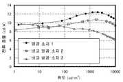
이와 같이, 유기 EL을 이용한 발광 소자는 발광 장치나 조명 장치 등에 대한 응용이 기대되고 있다. 한편, 유기 EL을 이용한 발광 소자에는 과제도 많다. 그 과제의 하나로서, 소비 전력의 저감을 들 수 있다. 소비 전력을 저감하기 위해서는 발광 소자의 구동 전압을 저감하는 것이 중요하다. 그리고, 유기 EL을 이용한 발광 소자는 흐르는 전류량에 의해 발광 강도가 정해지기 때문에, 구동 전압을 저감하기 위해서는 낮은 전압으로 많은 전류를 흘리는 것이 필요하게 된다.As described above, a light emitting device using an organic EL is expected to be applied to a light emitting device, a lighting device, and the like. On the other hand, there are many problems in the light emitting device using the organic EL. One of the problems is reduction of power consumption. In order to reduce the power consumption, it is important to reduce the driving voltage of the light emitting element. Since the light emission intensity of the light emitting device using the organic EL is determined by the amount of current flowing, it is necessary to flow a large amount of current with a low voltage in order to reduce the driving voltage.
지금까지, 구동 전압을 저감시키기 위한 방법으로서, 전극과 발광성의 유기 화합물을 포함하는 층과의 사이에 버퍼층을 형성하는 것이 시도되어 왔다. 예를 들면, 캠퍼설폰산을 도핑한 폴리아닐린(PANI)으로 이루어지는 버퍼층을 인듐 주석 산화물(ITO:indiumtinoxide)과 발광층과의 사이에 형성함으로써, 구동 전압을 저감할 수 있는 것이 알려져 있다(예를 들면, 비특허문헌 1 참조). 이것은 발광층에 대한 PANI의 캐리어 주입성이 우수하기 때문이라고 설명되어 있다. 또한, 비특허문헌 1에서는 버퍼층인 PANI도 전극의 일부라고 보고 있다는 점을 주목하라.Up to now, as a method for reducing the driving voltage, attempts have been made to form a buffer layer between the electrode and the layer containing a luminescent organic compound. For example, it is known that a driving voltage can be reduced by forming a buffer layer made of polyaniline (PANI) doped with camphorsulfonic acid between indium tin oxide (ITO) and a light emitting layer (see, for example, Non-Patent Document 1). It is explained that this is because the carrier injection property of PANI to the light emitting layer is excellent. Note that in the
그러나, 비특허문헌 1에 기재되어 있는 바와 같이, PANI는 막두께를 두껍게 하면 투과율이 나빠진다는 문제점이 있다. 구체적으로는 250 nm 정도의 막두께에서, 투과율은 70%를 밑돈다고 보고되어 있다. 즉, 버퍼층에 이용하고 있는 재료 자체의 투명성에 문제가 있기 때문에, 소자 내부에서 발생한 광을 효율 좋게 꺼낼 수 없다.However, as described in Non-Patent
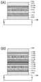
또, 특허문헌 1에 의하면, 발광 소자(특허문헌 1에서는 발광 유닛이라고 기재되어 있음)를 직렬로 접속함으로써, 어느 전류 밀도당의 휘도, 즉 전류 효율을 높이려는 시도가 이루어져 왔다. 특허문헌 1에서는 발광 소자를 직렬로 접속할 때의 접속 부분에, 유기 화합물과 금속 산화물(구체적으로는 산화 바나듐 및 산화 레늄)을 혼합한 층을 적용하고 있고, 이 층은 홀(정공)이나 전자를 발광 유닛에 주입할 수 있다고 생각되고 있다.According to
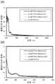
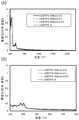
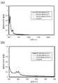
그러나, 특허문헌 1에 개시되어 있는 유기 화합물과 금속 산화물과의 혼합층은 실시예를 보아도 알 수 있는 바와 같이, 적외 영역뿐만 아니라 가시광 영역(500 nm 부근)에도 큰 흡수 피크를 볼 수 있어, 역시 투명성에 문제가 생기고 있다. 이것은 전하 이동 상호 작용에 의해 발생하는 흡수 밴드의 영향이다. 따라서, 역시 소자 내부에서 발생한 광을 효율 좋게 꺼내지 못하고, 소자의 발광 효율이 저하된다.
However, as can be seen from the examples, a mixed layer of an organic compound and a metal oxide disclosed in
따라서, 본 발명의 일 양태에서는 유기 화합물과 무기 화합물을 복합한 복합 재료로서, 캐리어 수송성이 높은 복합 재료를 제공하는 것을 과제의 하나로 한다. 또, 유기 화합물에 대한 캐리어 주입성이 높은 복합 재료를 제공하는 것을 과제의 하나로 한다. 또, 전하 이동 상호 작용에 의한 광흡수가 생기기 어려운 복합 재료를 제공하는 것을 과제의 하나로 한다.Accordingly, one object of the present invention is to provide a composite material having a composite of an organic compound and an inorganic compound, which has high carrier transportability. Another object of the present invention is to provide a composite material having high carrier injection property with respect to an organic compound. Another object of the present invention is to provide a composite material which is less prone to light absorption due to charge transfer interaction.
또, 본 발명의 일 양태는 이 복합 재료를 발광 소자에 적용함으로써, 발광 효율이 높은 발광 소자를 제공하는 것을 과제의 하나로 한다. 또, 구동 전압이 낮은 발광 소자를 제공하는 것을 과제의 하나로 한다. 또, 긴 수명의 발광 소자를 제공하는 것을 과제의 하나로 한다. 또, 이 발광 소자를 이용한 발광 장치, 이 발광 장치를 이용한 전자 기기, 또는 조명 장치를 제공하는 것을 과제의 하나로 한다.Another aspect of the present invention is to provide a light emitting device having high light emitting efficiency by applying this composite material to a light emitting device. Another object of the present invention is to provide a light emitting device having a low driving voltage. Another object of the present invention is to provide a light emitting element having a long lifetime. Another object of the present invention is to provide a light emitting device using the light emitting element, an electronic device using the light emitting device, or a lighting device.
또한, 이하에 개시하는 발명은 상기 과제의 적어도 어느 하나를 해결하는 것을 목적으로 한다는 점을 주목하라.
It should also be noted that the invention disclosed below aims at solving at least one of the above problems.
본 발명의 일 양태는 다이벤조티오펜 골격 또는 다이벤조퓨란 골격을 가지는 복소 고리 화합물과, 이 복소 고리 화합물에 대하여 전자 수용성을 나타내는 무기 화합물을 포함하는 복합 재료이다.One embodiment of the present invention is a composite material comprising a heterocyclic compound having a dibenzothiophene skeleton or a dibenzofuran skeleton and an inorganic compound exhibiting electron accepting property with respect to the heterocyclic compound.
티오펜 및 퓨란은 π 과잉계 헤테로 방향 고리이기 때문에, 모두 홀 수송성을 나타낸다. 따라서, 상기 복합 재료는 캐리어 수송성이 높다.Since thiophene and furan are π-hypertonic hetero-aromatic rings, they all exhibit hole-transporting properties. Therefore, the composite material has high carrier transportability.
또, 상기 복합 재료는 유기 화합물에 대한 캐리어 주입성이 높다. 또, 전하 이동 상호 작용에 의한 광흡수가 생기기 어렵다. 또, 가시광에 대한 투광성(이하, 투광성이라고 기재함)이 높다.In addition, the composite material has a high carrier injection property with respect to an organic compound. Also, light absorption due to charge transfer interaction is unlikely to occur. In addition, the transmittance to visible light (hereinafter referred to as transmittance) is high.
또, 본 발명의 일 양태는 다이벤조티오펜 골격 또는 다이벤조퓨란 골격의 4위에 탄소수 6 이상 70 이하의 치환기가 결합한 복소 고리 화합물과, 이 복소 고리 화합물에 대하여 전자 수용성을 나타내는 무기 화합물을 포함하는 복합 재료이다.One embodiment of the present invention is a process for producing a heterocyclic compound comprising a heterocyclic compound having a substituent group having 6 or more and 70 or less carbon atoms bonded to the dibenzothiophene skeleton or the dibenzofuran skeleton and an inorganic compound exhibiting electron accepting property to the heterocyclic compound It is a composite material.
다이벤조티오펜 골격 또는 다이벤조퓨란 골격의 4위에 치환기를 가지는 복소 고리 화합물을 복합 재료에 이용함으로써, 전하 이동 상호 작용에 기초한 광흡수의 발생을 억제할 수 있기 때문에, 바람직하고, 또 복합 재료의 막질이 안정화되기 때문에 바람직하다.It is preferable to use a heterocyclic compound having a substituent at the 4-position of the dibenzothiophene skeleton or the dibenzofuran skeleton in the composite material because the generation of light absorption based on the charge transfer interaction can be suppressed, It is preferable since the film quality is stabilized.
상기 복합 재료에 있어서, 이 치환기가 가지는 고리는 벤젠 고리, 나프탈렌 고리, 페난트렌 고리, 트라이페닐렌 고리, 플루오렌 고리, 다이벤조티오펜 고리, 다이벤조퓨란 고리로부터 선택되는 일종 또는 복수종인 것이 바람직하다. 이것에 의해, 전하 이동 상호 작용에 기초한 광흡수의 발생을 억제할 뿐만 아니라, 복소 고리 화합물 자체의 흡수 피크가 가시광 영역(380 nm∼760 nm)보다 단파장측에 생기도록 제어할 수 있기 때문에, 투광성이 특히 높은 복합 재료를 얻을 수 있다.In the composite material, the ring of the substituent is preferably one or more species selected from a benzene ring, a naphthalene ring, a phenanthrene ring, a triphenylen ring, a fluorene ring, a dibenzothiophene ring and a dibenzofuran ring Do. This makes it possible to control not only the occurrence of light absorption based on the charge transfer interaction but also the absorption peak of the heterocyclic compound itself on the shorter wavelength side than the visible light region (380 nm to 760 nm) This particularly high composite material can be obtained.
특히, 치환기가 가지는 고리는 벤젠 고리, 플루오렌 고리, 다이벤조티오펜 고리, 다이벤조퓨란 고리로부터 선택되는 일종 또는 복수종인 것이 바람직하다. 이것에 의해, 이 무기 화합물과의 사이에, 전하 이동 상호 작용에 기초한 광흡수가 거의 생기지 않게 된다.In particular, the ring of the substituent is preferably one kind or plural kinds selected from a benzene ring, a fluorene ring, a dibenzothiophene ring and a dibenzofuran ring. As a result, light absorption based on the charge transfer interaction with the inorganic compound hardly occurs.
또, 본 발명의 일 양태는 다이벤조티오펜 골격 또는 다이벤조퓨란 골격의 4위에 페닐기가 결합하여, 페닐기가 1 이상의 치환기를 가지고, 페닐기 및 1 이상의 치환기의 탄소수의 총합이 12 이상 70 이하인 복소 고리 화합물과, 이 복소 고리 화합물에 대하여 전자 수용성을 나타내는 무기 화합물을 포함하는 복합 재료이다.One embodiment of the present invention is a compound wherein a phenyl group is bonded to a 4-position of a dibenzothiophene skeleton or a dibenzofuran skeleton, the phenyl group has at least one substituent, the heterocyclic ring having a total of 12 or more and 70 or less carbon atoms of the phenyl group and at least one substituent A compound and an inorganic compound exhibiting electron-accepting property with respect to the heterocyclic compound.
다이벤조티오펜 골격 또는 다이벤조퓨란 골격의 4위에 공액이 작은 페닐기가 결합한 복소 고리 화합물을 복합 재료에 이용함으로써, 전하 이동 상호 작용에 기초한 광흡수의 발생을 억제할 수 있기 때문에, 바람직하다. 또, 복합 재료의 막질이 안정화되기 때문에 바람직하로, 또 공액이 퍼지기 어려워지기 때문에, 투광성 향상의 관점에서도 유효하다.It is preferable to use a heterocyclic compound having a dibenzothiophene skeleton or a dibenzofuran skeleton in which a phenyl group having a small conjugation degree is bonded to the composite material, because the generation of light absorption based on the charge transfer interaction can be suppressed. In addition, since the film quality of the composite material is stabilized, it is preferable, and since the conjugate is difficult to spread, it is also effective from the viewpoint of improving light transmittance.
상기 복합 재료에 있어서, 이 1 이상의 치환기가 가지는 고리는 각각 독립적으로, 벤젠 고리, 나프탈렌 고리, 페난트렌 고리, 트라이페닐렌 고리, 플루오렌 고리, 다이벤조티오펜 고리, 다이벤조퓨란 고리로부터 선택되는 일종 또는 복수종인 것이 바람직하다. 이것에 의해, 전하 이동 상호 작용에 기초한 광흡수의 발생을 억제할 뿐만 아니라, 복소 고리 화합물 자체의 흡수 피크가 가시광 영역보다 단파장측에 생기도록 제어할 수 있기 때문에, 특히 투광성이 높은 복합 재료를 얻을 수 있다.In the composite material, the rings of the at least one substituent are each independently selected from a benzene ring, a naphthalene ring, a phenanthrene ring, a triphenylene ring, a fluorene ring, a dibenzothiophene ring and a dibenzofuran ring It is preferable to use one species or plural species. As a result, it is possible to control not only the occurrence of light absorption based on the charge transfer interaction but also the absorption peak of the heterocyclic compound itself on the shorter wavelength side than in the visible light region, .
특히, 이 1 이상의 치환기가 가지는 고리는 각각 독립적으로, 벤젠 고리, 플루오렌 고리, 다이벤조티오펜 고리, 다이벤조퓨란 고리로부터 선택되는 일종 또는 복수종인 것이 바람직하다. 이것에 의해, 이 무기 화합물과의 사이에, 전하 이동 상호 작용에 기초한 광흡수가 거의 생기지 않게 된다.In particular, the rings of the at least one substituent are each independently preferably a benzene ring, a fluorene ring, a dibenzothiophene ring, or a dibenzofuran ring. As a result, light absorption based on the charge transfer interaction with the inorganic compound hardly occurs.
또, 본 발명의 일 양태는 일반식 (G1)로 나타내어지는 복소 고리 화합물과, 이 복소 고리 화합물에 대하여 전자 수용성을 나타내는 무기 화합물을 포함하는 복합 재료이다.One embodiment of the present invention is a composite material comprising a heterocyclic compound represented by the general formula (G1) and an inorganic compound exhibiting electron-accepting property to the heterocyclic compound.
[일반식 (G1)][General formula (G1)]

식 중, A는 산소 또는 유황을 나타내고, R1∼R7은 각각 독립적으로, 수소, 탄소수 1∼4의 알킬기, 또는 고리를 구성하는 탄소수가 6∼25의 아릴기를 나타내고, R8∼R12는 각각 독립적으로, 수소, 치환 혹은 무치환의 페닐기, 치환 혹은 무치환의 나프틸기, 치환 혹은 무치환의 페난트릴기, 치환 혹은 무치환의 트라이페닐레닐기, 치환 혹은 무치환의 플루오레닐기, 치환 혹은 무치환의 다이벤조티오페닐기, 또는 치환 혹은 무치환의 다이벤조퓨라닐기를 나타낸다. 단, R8∼R12 중, 적어도 하나는 치환 혹은 무치환의 페닐기, 치환 혹은 무치환의 나프틸기, 치환 혹은 무치환의 페난트릴기, 치환 혹은 무치환의 트라이페닐레닐기, 치환 혹은 무치환의 플루오레닐기, 치환 혹은 무치환의 다이벤조티오페닐기, 또는 치환 혹은 무치환의 다이벤조퓨라닐기를 나타냄을 주목하라.Wherein R1 to R7 each independently represent hydrogen, an alkyl group having 1 to 4 carbon atoms, or an aryl group having 6 to 25 carbon atoms constituting a ring, and R8 to R12 Each independently represent hydrogen, a substituted or unsubstituted phenyl group, a substituted or unsubstituted naphthyl group, a substituted or unsubstituted phenanthryl group, a substituted or unsubstituted triphenylenyl group, a substituted or unsubstituted fluorenyl group, A substituted or unsubstituted dibenzothiophenyl group, or a substituted or unsubstituted dibenzofuranyl group. Provided that at least one of R8 to R12 is a substituted or unsubstituted phenyl group, a substituted or unsubstituted naphthyl group, a substituted or unsubstituted phenanthryl group, a substituted or unsubstituted triphenylenyl group, a substituted or unsubstituted A fluorenyl group, a substituted or unsubstituted dibenzothiophenyl group, or a substituted or unsubstituted dibenzofuranyl group.
특히, R8∼R12는 각각 독립적으로, 수소, 치환 혹은 무치환의 페닐기, 치환 혹은 무치환의 플루오레닐기, 치환 혹은 무치환의 다이벤조티오페닐기, 또는 치환 혹은 무치환의 다이벤조퓨라닐기를 나타내는 것이 바람직하다. 단, R8∼R12 중, 적어도 하나는 치환 혹은 무치환의 페닐기, 치환 혹은 무치환의 플루오레닐기, 치환 혹은 무치환의 다이벤조티오페닐기, 또는 치환 혹은 무치환의 다이벤조퓨라닐기를 나타냄을 주목하라.In particular, each of R8 to R12 independently represents a hydrogen, a substituted or unsubstituted phenyl group, a substituted or unsubstituted fluorenyl group, a substituted or unsubstituted dibenzothiophenyl group, or a substituted or unsubstituted dibenzofuranyl Group. Provided that at least one of R8 to R12 represents a substituted or unsubstituted phenyl group, a substituted or unsubstituted fluorenyl group, a substituted or unsubstituted dibenzothiophenyl group, or a substituted or unsubstituted dibenzofuranyl group Please note.
또, 본 발명의 일 양태는 다이벤조티오펜 골격 또는 다이벤조퓨란 골격을 가지는 복소 고리 화합물과 천이 금속 산화물을 포함하는 복합 재료이다.One embodiment of the present invention is a composite material comprising a heterocyclic compound having a dibenzothiophene skeleton or a dibenzofuran skeleton and a transition metal oxide.
상기 복합 재료는 캐리어 수송성이 높다. 또, 유기 화합물에 대한 캐리어 주입성이 높다. 또, 전하 이동 상호 작용에 의한 광흡수가 생기기 어렵다. 또, 투광성이 높다.The composite material has high carrier transportability. In addition, the carrier injection property with respect to the organic compound is high. Also, light absorption due to charge transfer interaction is unlikely to occur. Also, the light transmittance is high.
또, 본 발명의 일 양태는 다이벤조티오펜 골격 또는 다이벤조퓨란 골격의 4위에 탄소수 6 이상 70 이하의 치환기가 결합한 복소 고리 화합물과, 천이 금속 산화물을 포함하는 복합 재료이다.One embodiment of the present invention is a composite material comprising a heterocyclic compound having a substituent group having 6 or more and 70 or less carbon atoms bonded to the dibenzothiophene skeleton or the dibenzofuran skeleton at 4 and a transition metal oxide.
다이벤조티오펜 골격 또는 다이벤조퓨란 골격의 4위에 치환기를 가지는 복소 고리 화합물을 복합 재료에 이용함으로써, 전하 이동 상호 작용에 기초한 광흡수의 발생을 억제할 수 있기 때문에, 바람직하다. 또, 복합 재료의 막질이 안정화되기 때문에, 바람직하다.It is preferable to use a heterocyclic compound having a substituent at the 4-position of the dibenzothiophene skeleton or the dibenzofuran skeleton in the composite material because the generation of light absorption based on the charge transfer interaction can be suppressed. It is also preferable because the film quality of the composite material is stabilized.
상기 복합 재료에 있어서, 이 치환기가 가지는 고리는 벤젠 고리, 나프탈렌 고리, 페난트렌 고리, 트라이페닐렌 고리, 플루오렌 고리, 다이벤조티오펜 고리, 다이벤조퓨란 고리로부터 선택되는 일종 또는 복수종인 것이 바람직하다. 이것에 의해, 전하 이동 상호 작용에 기초한 광흡수의 발생을 억제할 뿐만 아니라, 복소 고리 화합물 자체의 흡수 피크가 가시광 영역보다 단파장측에 생기도록 제어할 수 있기 때문에, 특히 투광성이 높은 복합 재료를 얻을 수 있다.In the composite material, the ring of the substituent is preferably one or more species selected from a benzene ring, a naphthalene ring, a phenanthrene ring, a triphenylen ring, a fluorene ring, a dibenzothiophene ring and a dibenzofuran ring Do. As a result, it is possible to control not only the occurrence of light absorption based on the charge transfer interaction but also the absorption peak of the heterocyclic compound itself on the shorter wavelength side than in the visible light region, .
특히, 이 치환기가 가지는 고리는 벤젠 고리, 플루오렌 고리, 다이벤조티오펜 고리, 다이벤조퓨란 고리로부터 선택되는 일종 또는 복수종인 것이 바람직하다. 이것에 의해, 이 천이 금속 산화물과의 사이에, 전하 이동 상호 작용에 기초한 광흡수가 거의 생기지 않게 된다.Particularly, the ring of the substituent is preferably one kind or plural kinds selected from a benzene ring, a fluorene ring, a dibenzothiophene ring and a dibenzofuran ring. As a result, light absorption based on the charge transfer interaction with the transition metal oxide is hardly generated.
또, 본 발명의 일 양태는 다이벤조티오펜 골격 또는 다이벤조퓨란 골격의 4위에 페닐기가 결합하여, 페닐기가 1 이상의 치환기를 가지고, 페닐기 및 1 이상의 치환기의 탄소수의 총합이 12 이상 70 이하인 복소 고리 화합물과 천이 금속 산화물을 포함하는 복합 재료이다.One embodiment of the present invention is a compound wherein a phenyl group is bonded to a 4-position of a dibenzothiophene skeleton or a dibenzofuran skeleton, the phenyl group has at least one substituent, the heterocyclic ring having a total of 12 or more and 70 or less carbon atoms of the phenyl group and at least one substituent Compound and a transition metal oxide.
다이벤조티오펜 골격 또는 다이벤조퓨란 골격의 4위에 공액이 작은 페닐기가 결합한 복소 고리 화합물을 복합 재료에 이용함으로써, 전하 이동 상호 작용에 기초한 광흡수의 발생을 억제할 수 있기 때문에 바람직하다. 또, 복합 재료의 막질이 안정화되기 때문에, 바람직하다. 또, 공액이 퍼지기 어려워지기 때문에, 투광성 향상의 관점에서도 유효하다.It is preferable to use a heterocyclic compound having a dibenzothiophene skeleton or dibenzofuran skeleton in which a phenyl group having a small conjugation is bonded at the 4th position of the dibenzothiophene skeleton or the dibenzofuran skeleton in a composite material because the occurrence of light absorption based on charge transfer interaction can be suppressed. It is also preferable because the film quality of the composite material is stabilized. In addition, since conjugation is less likely to spread, it is also effective from the viewpoint of improving light transmittance.
상기 복합 재료에 있어서, 이 1 이상의 치환기가 가지는 고리는 각각 독립적으로, 벤젠 고리, 나프탈렌 고리, 페난트렌 고리, 트라이페닐렌 고리, 플루오렌 고리, 다이벤조티오펜 고리, 다이벤조퓨란 고리로부터 선택되는 일종 또는 복수종인 것이 바람직하다. 이것에 의해, 전하 이동 상호 작용에 기초한 광흡수의 발생을 억제할 뿐만 아니라, 복소 고리 화합물 자체의 흡수 피크가 가시광 영역보다 단파장측에 생기도록 제어할 수 있기 때문에, 특히 투광성이 높은 복합 재료를 얻을 수 있다.In the composite material, the rings of the at least one substituent are each independently selected from a benzene ring, a naphthalene ring, a phenanthrene ring, a triphenylene ring, a fluorene ring, a dibenzothiophene ring and a dibenzofuran ring It is preferable to use one species or plural species. As a result, it is possible to control not only the occurrence of light absorption based on the charge transfer interaction but also the absorption peak of the heterocyclic compound itself on the shorter wavelength side than in the visible light region, .
특히, 이 1 이상의 치환기가 가지는 고리는 각각 독립적으로, 벤젠 고리, 플루오렌 고리, 다이벤조티오펜 고리, 다이벤조퓨란 고리로부터 선택되는 일종 또는 복수종인 것이 바람직하다. 이것에 의해, 이 천이 금속 산화물과의 사이에, 전하 이동 상호 작용에 기초한 광흡수가 거의 생기지 않게 된다.In particular, the rings of the at least one substituent are each independently preferably a benzene ring, a fluorene ring, a dibenzothiophene ring, or a dibenzofuran ring. As a result, light absorption based on the charge transfer interaction with the transition metal oxide is hardly generated.
또, 본 발명의 일 양태는 일반식 (G1)로 나타내어지는 복소 고리 화합물과 천이 금속 산화물을 포함하는 복합 재료이다.One embodiment of the present invention is a composite material comprising a heterocyclic compound represented by the general formula (G1) and a transition metal oxide.
[일반식 (G1)][General formula (G1)]

식 중, A는 산소 또는 유황을 나타내고, R1∼R7은 각각 독립적으로, 수소, 탄소수 1∼4의 알킬기, 또는 고리를 구성하는 탄소수가 6∼25의 아릴기를 나타내고, R8∼R12는 각각 독립적으로, 수소, 치환 혹은 무치환의 페닐기, 치환 혹은 무치환의 나프틸기, 치환 혹은 무치환의 페난트릴기, 치환 혹은 무치환의 트라이페닐레닐기, 치환 혹은 무치환의 플루오레닐기, 치환 혹은 무치환의 다이벤조티오페닐기, 또는 치환 혹은 무치환의 다이벤조퓨라닐기를 나타낸다. 단, R8∼R12 중, 적어도 하나는 치환 혹은 무치환의 페닐기, 치환 혹은 무치환의 나프틸기, 치환 혹은 무치환의 페난트릴기, 치환 혹은 무치환의 트라이페닐레닐기, 치환 혹은 무치환의 플루오레닐기, 치환 혹은 무치환의 다이벤조티오페닐기, 또는 치환 혹은 무치환의 다이벤조퓨라닐기를 나타냄을 주목하라.Wherein R1 to R7 each independently represent hydrogen, an alkyl group having 1 to 4 carbon atoms, or an aryl group having 6 to 25 carbon atoms constituting a ring, and R8 to R12 Each independently represent hydrogen, a substituted or unsubstituted phenyl group, a substituted or unsubstituted naphthyl group, a substituted or unsubstituted phenanthryl group, a substituted or unsubstituted triphenylenyl group, a substituted or unsubstituted fluorenyl group, A substituted or unsubstituted dibenzothiophenyl group, or a substituted or unsubstituted dibenzofuranyl group. Provided that at least one of R8 to R12 is a substituted or unsubstituted phenyl group, a substituted or unsubstituted naphthyl group, a substituted or unsubstituted phenanthryl group, a substituted or unsubstituted triphenylenyl group, a substituted or unsubstituted A fluorenyl group, a substituted or unsubstituted dibenzothiophenyl group, or a substituted or unsubstituted dibenzofuranyl group.
특히, R8∼R12는 각각 독립적으로, 수소, 치환 혹은 무치환의 페닐기, 치환 혹은 무치환의 플루오레닐기, 치환 혹은 무치환의 다이벤조티오페닐기, 또는 치환 혹은 무치환의 다이벤조퓨라닐기를 나타내는 것이 바람직하다. 단, R8∼R12 중, 적어도 하나는 치환 혹은 무치환의 페닐기, 치환 혹은 무치환의 플루오레닐기, 치환 혹은 무치환의 다이벤조티오페닐기, 또는 치환 혹은 무치환의 다이벤조퓨라닐기를 나타냄을 주목하라.In particular, each of R8 to R12 independently represents a hydrogen, a substituted or unsubstituted phenyl group, a substituted or unsubstituted fluorenyl group, a substituted or unsubstituted dibenzothiophenyl group, or a substituted or unsubstituted dibenzofuranyl Group. Provided that at least one of R8 to R12 represents a substituted or unsubstituted phenyl group, a substituted or unsubstituted fluorenyl group, a substituted or unsubstituted dibenzothiophenyl group, or a substituted or unsubstituted dibenzofuranyl group Please note.
또, 상기 복합 재료에 포함되는 천이 금속 산화물로서는 티탄 산화물, 바나듐 산화물, 몰리브덴 산화물, 텅스텐 산화물, 레늄 산화물, 루테늄 산화물, 크롬 산화물, 지르코늄 산화물, 하프늄 산화물, 탄탈 산화물, 은 산화물로부터 선택되는 일종 또는 복수종인 것이 바람직하다.The transition metal oxide included in the composite material may be one or more selected from titanium oxide, vanadium oxide, molybdenum oxide, tungsten oxide, rhenium oxide, ruthenium oxide, chromium oxide, zirconium oxide, hafnium oxide, tantalum oxide, It is desirable to be species.
상기 복합 재료에 이용하는 복소 고리 화합물의 최고 피점유 궤도 준위(HOMO 준위)는 광전자 분광법에서의 측정값이 -5.7 eV 이하인 것이 바람직하다.The highest occupied molecular orbital level (HOMO level) of the heterocyclic compound used in the composite material is preferably -5.7 eV or less as measured by photoelectron spectroscopy.
또, 본 발명의 일 양태는 한쌍의 전극 간에 발광 물질을 포함하는 층(이하, EL층이라고도 기재함)를 가진다. 발광 물질을 포함하는 층은 상기 복합 재료를 포함하는 층을 가진다.In addition, one embodiment of the present invention has a layer containing a light emitting material (hereinafter also referred to as an EL layer) between a pair of electrodes. The layer containing the luminescent material has a layer containing the composite material.
상기 발광 소자에 있어서, 복합 재료를 포함하는 층은 한쌍의 전극 중, 양극으로서 기능하는 전극과 접하는 것이 바람직하다. 또, 복합 재료를 포함하는 층은 한쌍의 전극 중, 음극으로서 기능하는 전극과 접하는 것이 바람직하다.In the light emitting element, it is preferable that the layer containing the composite material is in contact with an electrode functioning as an anode among a pair of electrodes. It is preferable that the layer containing the composite material is in contact with an electrode functioning as a cathode among a pair of electrodes.
또, 상기 발광 소자는 복합 재료를 포함하는 층을 2층 가지고 있어도 좋고, 이 복합 재료를 포함하는 층 중, 한쪽의 층은 한쌍의 전극 중 양극으로서 기능하는 전극과 접하고, 다른 한쪽의 층은 음극으로서 기능하는 전극과 접하는 것이 바람직하다.The light emitting device may have two layers including a composite material. Of the layers including the composite material, one of the layers is in contact with an electrode functioning as an anode in the pair of electrodes, and the other layer is in contact with the cathode It is preferable to contact with the electrode functioning as the electrode.
또, 본 발명의 일 양태는 한쌍의 전극 간에 발광 물질을 포함하는 층을 복수 가지고, 복수의 발광 물질을 포함하는 층의 사이에, 상기 복합 재료를 포함하는 층을 가지는 발광 소자이다. 즉, 복수의 발광 유닛을 적층한 구성의 유기 EL 발광 소자(탠덤형의 유기 EL 발광 소자)에서의 중간층(전하 발생층이라고도 기재함)에, 상기 복합 재료를 이용할 수 있다.An embodiment of the present invention is a light-emitting element having a plurality of layers including a light-emitting substance between a pair of electrodes and a layer containing the composite material between layers including a plurality of light-emitting materials. That is, the composite material can be used for an intermediate layer (also referred to as a charge generation layer) in an organic EL light emitting element (tandem organic EL light emitting element) having a plurality of light emitting units stacked.
또, 본 발명의 일 양태는 상기 발광 소자를 가지는 발광 장치이다. 또, 이 발광 장치를 표시부에 가지는 전자 기기이다. 또, 이 발광 소자를 발광부에 가지는 조명 장치이다.An embodiment of the present invention is a light emitting device having the light emitting element. It is an electronic device having this light emitting device in the display portion. Further, this is a lighting device having the light emitting element in the light emitting portion.
본 발명의 일 양태에 따르면, 유기 화합물과 무기 화합물을 복합한 복합 재료이며, 캐리어 수송성이 높은 복합 재료를 제공할 수 있다. 또, 유기 화합물에 대한 캐리어 주입성이 높은 복합 재료를 제공할 수 있다. 또, 전하 이동 상호 작용에 의한 광흡수가 생기기 어려운 복합 재료를 제공할 수 있다.According to one aspect of the present invention, there can be provided a composite material having a composite of an organic compound and an inorganic compound and having high carrier transportability. It is also possible to provide a composite material having high carrier injection property with respect to an organic compound. In addition, it is possible to provide a composite material in which light absorption is less likely to occur due to charge transfer interaction.
또, 본 발명의 일 양태에 따르면, 이 복합 재료를 발광 소자에 적용함으로써, 발광 효율이 높은 발광 소자를 제공할 수 있다. 또, 구동 전압이 낮은 발광 소자를 제공할 수 있다. 또, 긴 수명의 발광 소자를 제공할 수 있다. 또, 이 발광 소자를 이용한 발광 장치, 이 발광 장치를 이용한 전자 기기, 또는 조명 장치를 제공할 수 있다.
According to an embodiment of the present invention, by applying this composite material to a light emitting element, a light emitting element having high light emitting efficiency can be provided. In addition, a light emitting element having a low driving voltage can be provided. In addition, it is possible to provide a light-emitting element having a long lifetime. It is also possible to provide a light emitting device using the light emitting element, an electronic device using the light emitting device, or a lighting device.
도 1은 본 발명의 일 양태의 발광 소자를 나타낸 도면.
도 2는 본 발명의 일 양태의 발광 소자를 나타낸 도면.
도 3은 본 발명의 일 양태의 발광 장치를 나타낸 도면.
도 4는 본 발명의 일 양태의 발광 장치를 나타낸 도면.
도 5는 본 발명의 일 양태의 전자 기기를 나타낸 도면.
도 6은 본 발명의 일 양태의 조명 장치를 나타낸 도면.
도 7은 본 발명의 일 양태의 복합 재료의 흡광도를 나타낸 도면.
도 8은 본 발명의 일 양태의 복합 재료의 흡광도를 나타낸 도면.
도 9는 본 발명의 일 양태의 복합 재료의 흡광도를 나타낸 도면.
도 10은 본 발명의 일 양태의 복합 재료의 흡광도를 나타낸 도면.
도 11은 본 발명의 일 양태의 복합 재료의 흡광도를 나타낸 도면.
도 12는 본 발명의 일 양태의 복합 재료의 흡광도를 나타낸 도면.
도 13은 본 발명의 일 양태의 복합 재료의 흡광도를 나타낸 도면.
도 14는 본 발명의 일 양태의 복합 재료의 흡광도를 나타낸 도면.
도 15는 본 발명의 일 양태의 복합 재료의 흡광도를 나타낸 도면.
도 16은 실시예의 발광 소자를 나타낸 도면.
도 17은 실시예 2의 발광 소자의 전압-휘도 특성을 나타낸 도면.
도 18은 실시예 2의 발광 소자의 휘도-전류 효율 특성을 나타낸 도면.
도 19는 실시예 2의 발광 소자의 신뢰성 시험의 결과를 나타낸 도면.
도 20은 실시예 3의 발광 소자의 전압-휘도 특성을 나타낸 도면.
도 21은 실시예 3의 발광 소자의 휘도-전류 효율 특성을 나타낸 도면.
도 22는 실시예 3의 발광 소자의 신뢰성 시험의 결과를 나타낸 도면.
도 23은 실시예 4의 발광 소자의 전압-휘도 특성을 나타낸 도면.
도 24는 실시예 4의 발광 소자의 휘도-전류 효율 특성을 나타낸 도면.
도 25는 본 발명의 일 양태의 복합 재료의 흡광도를 나타낸 도면.
도 26은 본 발명의 일 양태의 복합 재료의 흡광도를 나타낸 도면.
도 27은 본 발명의 일 양태의 복합 재료의 흡광도를 나타낸 도면.
도 28은 본 발명의 일 양태의 복합 재료의 흡광도를 나타낸 도면.
도 29는 본 발명의 일 양태의 복합 재료의 흡광도를 나타낸 도면.
도 30은 실시예 6의 발광 소자의 전압-휘도 특성을 나타낸 도면.
도 31은 실시예 6의 발광 소자의 휘도-전류 효율 특성을 나타낸 도면.
도 32는 실시예 6의 발광 소자의 신뢰성 시험의 결과를 나타낸 도면.
도 33은 실시예 7의 발광 소자의 전압-휘도 특성을 나타낸 도면.
도 34는 실시예 7의 발광 소자의 휘도-전류 효율 특성을 나타낸 도면.
도 35는 실시예 8의 발광 소자의 전압-휘도 특성을 나타낸 도면.
도 36은 실시예 8의 발광 소자의 휘도-전류 효율 특성을 나타낸 도면.
도 37은 실시예 9의 발광 소자의 전압-휘도 특성을 나타낸 도면.
도 38은 실시예 9의 발광 소자의 휘도-전류 효율 특성을 나타낸 도면.
도 39는 PCzPA와 그 복합 재료의 흡광도를 나타낸 도면.
도 40은 NPB와 그 복합 재료의 흡광도를 나타낸 도면.
도 41은 실시예 10의 ESR 측정의 결과에 관한 도면.
도 42는 실시예 10의 ESR 측정의 결과에 관한 도면.BRIEF DESCRIPTION OF THE DRAWINGS FIG. 1 shows a light emitting device according to an embodiment of the present invention. FIG.
2 illustrates a light emitting device according to an embodiment of the present invention.
3 is a view showing a light emitting device of one embodiment of the present invention.
4 is a view showing a light emitting device of an embodiment of the present invention.
5 is a view showing an electronic apparatus according to an embodiment of the present invention.
6 shows a lighting device of an aspect of the invention.
Figure 7 illustrates the absorbance of a composite material of one embodiment of the present invention.
Figure 8 illustrates the absorbance of a composite material of an embodiment of the invention.
9 is a diagram illustrating the absorbance of a composite material of an embodiment of the present invention.
10 is a diagram illustrating the absorbance of a composite material of an embodiment of the present invention.
11 is a diagram illustrating the absorbance of a composite material of an embodiment of the present invention.
12 is a diagram showing the absorbance of a composite material of an embodiment of the present invention.
13 is a diagram showing the absorbance of a composite material of one embodiment of the present invention.
Figure 14 illustrates the absorbance of a composite material of one embodiment of the present invention.
15 is a diagram showing the absorbance of a composite material of one embodiment of the present invention.
16 is a view showing a light emitting device of the embodiment.
17 is a graph showing voltage-luminance characteristics of the light emitting device of Example 2. Fig.
18 is a graph showing luminance-current efficiency characteristics of the light emitting device of Example 2. Fig.
19 is a view showing a result of a reliability test of a light emitting device of Example 2. Fig.
20 is a diagram showing voltage-luminance characteristics of the light-emitting device of Example 3. Fig.
21 is a graph showing the luminance-current efficiency characteristics of the light emitting device of Example 3. Fig.
22 is a diagram showing a result of a reliability test of the light emitting device of Example 3. Fig.
23 is a view showing voltage-luminance characteristics of the light-emitting device of Example 4. Fig.
24 is a graph showing luminance-current efficiency characteristics of the light-emitting device of Example 4. Fig.
Figure 25 illustrates the absorbance of a composite material of an aspect of the present invention.
26 illustrates absorbance of a composite material of an embodiment of the present invention.
Figure 27 illustrates the absorbance of a composite material of an embodiment of the present invention.
28 illustrates absorbance of a composite material of an embodiment of the present invention.
29 illustrates absorbance of a composite material of an embodiment of the present invention.
30 is a diagram showing voltage-luminance characteristics of the light emitting device of Example 6. Fig.
31 is a graph showing luminance-current efficiency characteristics of the light emitting device of Example 6. Fig.
32 is a view showing a result of a reliability test of the light emitting device of Example 6. Fig.
33 is a view showing voltage-luminance characteristics of the light-emitting device of Example 7. Fig.
34 is a graph showing the luminance-current efficiency characteristics of the light emitting device of Example 7. Fig.
35 is a diagram showing voltage-luminance characteristics of the light-emitting device of Example 8. Fig.
36 is a graph showing the luminance-current efficiency characteristics of the light emitting device of Example 8. Fig.
37 is a view showing voltage-luminance characteristics of the light-emitting device of Example 9. Fig.
38 is a graph showing luminance-current efficiency characteristics of the light-emitting device of Example 9. Fig.
39 is a diagram showing the absorbance of PCzPA and its composite material.
40 is a diagram showing the absorbance of NPB and its composite material.
41 is a diagram relating to the result of the ESR measurement of
42 is a diagram relating to the results of the ESR measurement of the tenth embodiment.
실시형태에 대하여, 도면을 이용하여 상세하게 설명한다. 단, 본 발명은 이하의 설명에 한정되는 것은 아니고, 본 발명의 취지 및 그 범위로부터 일탈하는 일 없이 그 형태 및 상세한 사항을 다양하게 변경할 수 있다는 것은 당업자라면 용이하게 이해할 수 있을 것이다. 따라서, 본 발명은 이하에 나타내는 실시형태의 기재 내용에 한정하여 해석되는 것은 아니다. 또한, 이하에 설명하는 발명의 구성에 있어서, 동일 부분 또는 동일한 기능을 가지는 부분에는 동일한 부호를 다른 도면간에 공통으로 이용하고 그 반복의 설명은 생략한다.Embodiments will be described in detail with reference to the drawings. It should be understood, however, that the present invention is not limited to the following description, and that various changes in form and details may be made therein without departing from the spirit and scope of the present invention. Therefore, the present invention is not construed as being limited to the description of the embodiments described below. In the following description of the present invention, the same reference numerals are used for the same portions or portions having the same function, and description of repetition thereof will be omitted.
우선, 본 발명의 배경이 되는 기술과 본 발명과의 차이에 대하여, 개요를 설명한다. 특허문헌 1에 나타내는 바와 같이, 방향족 아민과 전자 수용성의 무기 화합물이 혼합된 복합 재료는 전자 수용성의 무기 화합물이 방향족 아민으로부터 전자를 빼앗음으로써, 방향족 아민에 홀이, 무기 화합물에 전자가 발생한다고 해석되어 있다. 바꿔 말하면, 이러한 복합 재료는 방향족 아민과 전자 수용성의 무기 화합물이 전하 이동 착체를 형성하고 있다고 해석된다. 그리고, 이러한 현상을 이용하여, 지금까지 캐리어 수송성, 캐리어 주입성이 뛰어난 복합 재료가 몇 개인가 보고되어 있다.First, the outline of the difference between the technique as the background of the present invention and the present invention will be described. As shown in
그러나 이러한 경우, 일반적으로는 전하 이동 상호 작용에 기초한 흡수 밴드가 발생하는 것이 알려져 있다. 이 흡수 밴드는 짙은 적색∼근적외 영역에 발생한다고 알려져 있지만, 실제로는 많은 경우, 가시광 영역에도 흡수 밴드가 생긴다. 예를 들면, 4,4'-비스[N-(1-나프틸)-N-페닐아미노]바이페닐(약칭:NPB 또는 α-NPD)과 산화 바나듐, 또는 NPB와 산화 몰리브덴을 혼합한 복합 재료는 1300 nm 부근의 흡수 밴드 이외에, 500 nm 부근에도 흡수 밴드가 생긴다. 이것은 발광 소자와 같은 광학 디바이스에서는 큰 단점이 된다.However, in such a case, it is generally known that an absorption band is generated based on the charge transfer interaction. This absorption band is known to occur in a deep red to near infrared region, but in many cases, absorption bands also occur in the visible light region. For example, a composite material obtained by mixing 4,4'-bis [N- (1-naphthyl) -N-phenylamino] biphenyl (abbreviated as NPB or? -NPD) with vanadium oxide or NPB and molybdenum oxide Has an absorption band near 500 nm in addition to the absorption band around 1300 nm. This is a major drawback in optical devices such as light emitting devices.
본 발명자들은 다이벤조퓨란 골격 혹은 다이벤조티오펜 골격을 포함하는 복소 고리 화합물과 전자 수용성을 나타내는 무기 화합물, 또는 이 복소 고리 화합물과 천이 금속 산화물을 복합시킴으로써, 전하 이동 상호 작용에 기초한 광흡수를 확인할 수 없음(거의 발생하지 않음)에도 불구하고, 뛰어난 캐리어 수송성이나 캐리어 주입성을 발현할 수 있다는 것을 알아냈다. 종래, 전하 이동 상호 작용에 의해 발생하는 홀 및 전자가, 캐리어 수송성·캐리어 주입성 발현의 요소라고 생각되고 있었기 때문에, 전하 이동 상호 작용에 의한 광흡수가 명확하게 관찰되지 않음에도 불구하고 뛰어난 캐리어 수송성이나 캐리어 주입성을 발현할 수 있는 본 발명은, 그 일반론과는 모순되어, 예측 불가능의 놀랄만한 기능이라고 할 수 있다.The present inventors confirmed the optical absorption based on the charge transfer interaction by combining a heterocyclic compound containing a dibenzofuran skeleton or a dibenzothiophene skeleton with an inorganic compound exhibiting electron accepting property or a heterocyclic compound and a transition metal oxide It is possible to exhibit excellent carrier transportability and carrier injecting property despite the fact that there is no (almost no occurrence). Conventionally, holes and electrons generated by charge transfer interaction are thought to be components of carrier transportability and carrier injection characteristics. Therefore, although light absorption due to charge transfer interaction is not clearly observed, excellent carrier transportability Or carrier entanglement, is inconsistent with the general theory, and can be said to be an unpredictable and remarkable function.
또한, 다이벤조티오펜이나 다이벤조퓨란은 그 자체의 에너지 갭이 크다. 따라서, 다이벤조퓨란 골격 혹은 다이벤조티오펜 골격을 포함함으로써, 이 복소 고리 화합물 자체가 가시광 영역에 흡수 피크를 가지지 않는 화합물이 되도록 설계할 수 있다. 따라서, 투광성 향상의 관점에서 큰 이점이 있다.Further, dibenzothiophene or dibenzofurane has a large energy gap in itself. Therefore, by including the dibenzofuran skeleton or the dibenzothiophene skeleton, the heterocyclic compound itself can be designed to be a compound having no absorption peak in the visible light region. Therefore, there is a great advantage in terms of light transmittance improvement.
또, 다이벤조티오펜이나 다이벤조퓨란은 사이클릭 볼타메트리(CV) 측정에 의하면, HOMO 준위가 -6 eV 이하로 매우 낮다. 따라서, 다이벤조퓨란 골격 또는 다이벤조티오펜 골격을 포함하는 복소 고리 화합물 단체는 다른 유기 화합물에 대한 정공 주입성은 우수하다고 생각되지만, Al이나 ITO로 대표되는 도전 재료(일 함수가 3∼5 eV 정도)로부터 정공을 받는 것은 곤란하다고 생각된다. 그러나, 본 발명의 일 양태와 같은 복합 재료를 형성함으로써, 다른 유기 화합물에 대한 뛰어난 정공 주입성을 유지하면서, 전극으로부터의 정공 주입성의 문제점을 극복할 수 있다. 이러한 복합 재료의 성질은 발광 소자에 이용했을 때에, 구동 전압의 저감에 기여한다. 또, 투광성이 높기 때문에, 발광 효율을 높일 수 있다. 또, 깊은 HOMO 준위에 의해 발광 소자 중에 캐리어의 축적을 방지할 수 있다고 생각되기 때문에, 장수명화를 달성할 수 있다.The dibenzothiophene or dibenzofuran has a very low HOMO level of -6 eV or less according to cyclic voltammetry (CV) measurement. Therefore, although it is considered that the heterocyclic compound having a dibenzofuran skeleton or a dibenzothiophene skeleton has good hole injectability with respect to other organic compounds, it is preferable to use a conductive material represented by Al or ITO (having a work function of about 3 to 5 eV It is considered difficult to receive the holes. However, by forming the composite material as one embodiment of the present invention, it is possible to overcome the problem of hole injection property from the electrode while maintaining excellent hole injection property with respect to other organic compounds. The properties of such a composite material contribute to the reduction of the driving voltage when used in a light emitting device. Further, since the light transmitting property is high, the light emitting efficiency can be increased. In addition, it is considered that accumulation of carriers in the light emitting element can be prevented by the deep HOMO level, so that longevity can be achieved.
이하에서는 본 발명의 양태에 대해, 구체적인 예를 열거하면서 설명한다.Hereinafter, embodiments of the present invention will be described with reference to specific examples.
(실시형태 1)(Embodiment 1)
본 실시형태에서는 본 발명의 일 양태의 복합 재료에 대해 설명한다.In this embodiment, a composite material according to an embodiment of the present invention will be described.
본 발명의 일 양태의 복합 재료는 특정 골격을 가지는 유기 화합물과 무기 화합물과의 복합 재료이다. 본 발명의 일 양태의 복합 재료의 제작 방법에 한정은 없고, 예를 들면, 이 유기 화합물과 무기 화합물을 동시에 증착하는 공증착법에 의해 형성할 수 있다. 본 발명의 일 양태의 복합 재료에 있어서, 유기 화합물과 무기 화합물의 혼합비는 질량비로 8:1∼1:2( = 유기 화합물:무기 화합물) 정도가 바람직하고, 더욱 바람직하게는 4:1∼1:1( = 유기 화합물:무기 화합물)이다. 혼합비는 복합 재료를 공증착법에 의해 형성하는 경우는 유기 화합물과 무기 화합물의 증착 레이트를 각각 조절하는 것에 의해 제어할 수 있다.The composite material of one embodiment of the present invention is a composite material of an organic compound and an inorganic compound having a specific skeleton. The method for producing the composite material according to an embodiment of the present invention is not limited. For example, it can be formed by a co-evaporation method in which the organic compound and the inorganic compound are vapor-deposited at the same time. In the composite material of one embodiment of the present invention, the mixing ratio of the organic compound and the inorganic compound is preferably about 8: 1 to 1: 2 (= organic compound: inorganic compound) in a mass ratio, more preferably about 4: : 1 (= organic compound: inorganic compound). The mixing ratio can be controlled by adjusting the deposition rates of the organic compound and the inorganic compound when the composite material is formed by the coevaporation method.
우선, 본 발명의 일 양태의 복합 재료에 이용하는 것이 가능한 유기 화합물은 다이벤조티오펜 골격 또는 다이벤조퓨란 골격을 가지는 복소 고리 화합물이다.First, the organic compound that can be used for the composite material of one embodiment of the present invention is a heterocyclic compound having a dibenzothiophene skeleton or a dibenzofuran skeleton.
이 복소 고리 화합물을 복합 재료에 이용함으로써, 캐리어 수송성이 높은 재료로 할 수 있다. 또, 유기 화합물에 대한 캐리어 주입성이 높은 재료로 할 수 있다. 또, 무기 화합물과의 전하 이동 상호 작용에 의한 광흡수가 생기기 어려운 재료로 할 수 있다. 또, 이 복소 고리 화합물을 복합 재료에 이용함으로써, 투광성이 높은 재료로 할 수 있다.By using the heterocyclic compound in a composite material, a material having high carrier transportability can be obtained. In addition, a material having high carrier injection ability with respect to an organic compound can be obtained. It is also possible to obtain a material which is less prone to light absorption due to the charge transfer interaction with the inorganic compound. Further, by using the heterocyclic compound for a composite material, a material having high light transmittance can be obtained.
특히, 다이벤조티오펜 골격 또는 다이벤조퓨란 골격의 4위에 탄소수 6 이상 70 이하의 치환기가 결합한 복소 고리 화합물을 이용하는 것이 바람직하다. 다이벤조티오펜 골격 또는 다이벤조퓨란 골격의 4위에 치환기를 가지는 복소 고리 화합물을 복합 재료에 이용함으로써, 전하 이동 상호 작용에 기초한 광흡수의 발생을 억제할 수 있기 때문이다. 또, 다이벤조티오펜이나 다이벤조퓨란이 4위에 벌키한(부피가 큰) 치환기(예를 들면 탄소수가 6 이상)를 가지는 경우, 다이벤조티오펜이나 다이벤조퓨란과 이 치환기와의 입체 장애에 의해, 분자 전체가 입체적인 골격이 된다. 이것에 의해, 복합 재료의 막질이 안정화된다. 또, 이 복합 재료를 제작할 때에는, 이 복소 고리 화합물과 무기 화합물을 공증착하는 것이 바람직하지만, 이 경우는 이 복소 고리 화합물이 기화하기 쉬운 것이 바람직하다. 따라서, 분자량의 관점으로부터, 이 치환기의 탄소수는 70 이하인 것이 바람직하다. 또한, 이 복소 고리 화합물의 분자량으로서는 1200 이하 정도가 바람직하다.Particularly, it is preferable to use a heterocyclic compound having a substituent group having 6 or more and 70 or less carbon atoms bonded to the dibenzothiophene skeleton or the dibenzofuran skeleton at the 4-position thereof. It is possible to suppress the occurrence of light absorption based on the charge transfer interaction by using a heterocyclic compound having a substituent on the 4-position of the dibenzothiophene skeleton or the dibenzofuran skeleton in the composite material. Further, when dibenzothiophene or dibenzofuran has a bulky substituent (for example, 6 or more carbon atoms) at the 4th position, dibenzothiophene or dibenzofurane and a sterically hindered The whole molecule becomes a three-dimensional skeleton. As a result, the film quality of the composite material is stabilized. When this composite material is produced, it is preferable to co-deposit the heterocyclic compound and the inorganic compound, but in this case, it is preferable that the heterocyclic compound is easily vaporized. Therefore, from the viewpoint of the molecular weight, the number of carbon atoms of the substituent is preferably 70 or less. The molecular weight of the heterocyclic compound is preferably about 1200 or less.
또한, 본 발명자들이 지금까지 실험 및 검토를 행해 온 결과로는 방향족 탄화 수소 화합물(예를 들면 안트라센 화합물)과 무기 화합물을 혼합했을 때, 방향족 탄화 수소 화합물과 무기 화합물의 혼합비에서의 무기 화합물의 비율이 낮은 경우에는 혼합에 의해 형성되는 복합 재료는 결정화하기 쉽다. 반대로, 무기 화합물의 비율이 높은 경우에는 결정화는 억제할 수 있지만, 방향족 탄화 수소 화합물이 가지는 골격(예를 들면 안트라센 골격)과 무기 화합물과의 전하 이동 상호 작용에 유래한 약간의 흡수 피크가 가시광 영역에서 증대한다. 한편, 본 발명의 일 양태에 나타내는 바와 같이, 다이벤조티오펜 골격 또는 다이벤조퓨란 골격의 4위에 치환기가 결합한 복소 고리 화합물을 이용하는 경우는 예를 들면 이 치환기에 안트라센 골격을 포함하고, 또한 무기 화합물의 비율이 낮은 경우에도, 복합 재료의 결정화는 억제되어 복합 재료의 막질이 안정화된다. 따라서, 본 발명의 일 양태의 복합 재료의 경우에는 복소 고리 화합물이 안트라센 골격을 포함하고 있었다고 하더라도, 결정화를 억제할 목적으로 무기 화합물의 비율을 높게 할 필요가 없고, 전하 이동 상호 작용에 유래하는 흡수 피크가 가시광 영역에 관측되는 것을 막을 수 있다.The present inventors have conducted experiments and studies so far on the basis of the fact that when an aromatic hydrocarbon compound (for example, an anthracene compound) and an inorganic compound are mixed, the ratio of the inorganic compound in the mixing ratio of the aromatic hydrocarbon compound and the inorganic compound Is low, the composite material formed by mixing tends to crystallize. Conversely, when the ratio of the inorganic compound is high, the crystallization can be suppressed. However, a slight absorption peak derived from the charge transfer interaction between the skeleton (for example, an anthracene skeleton) of the aromatic hydrocarbon compound and the inorganic compound, . On the other hand, as shown in an embodiment of the present invention, when a heterocyclic compound having a substituent bonded to the 4-position of the dibenzothiophene skeleton or the dibenzofuran skeleton is used, for example, the substituent includes an anthracene skeleton, The crystallization of the composite material is suppressed and the film quality of the composite material is stabilized. Therefore, in the case of the composite material of one embodiment of the present invention, even if the heterocyclic compound contains an anthracene skeleton, it is not necessary to increase the ratio of the inorganic compound for the purpose of suppressing the crystallization and the absorption derived from the charge- It is possible to prevent the peak from being observed in the visible light region.
또, 본 발명자들이 지금까지 실험 및 검토를 행해 온 결과로는 아릴 카바졸 화합물과 무기 화합물을 혼합했을 때도, 아릴 카바졸 화합물과 무기 화합물의 혼합비에 있어서의 무기 화합물의 비율이 낮은 경우에는 혼합에 의해 형성되는 복합 재료는 결정화하기 쉽다. 반대로, 무기 화합물의 비율이 높은 경우에는 결정화는 억제할 수 있지만, 아릴 카바졸 골격과 무기 화합물과의 전하 이동 상호 작용에 유래한 약간의 흡수 피크가 가시광 영역에서 증대한다. 한편, 본 발명의 일 양태에 나타내는 바와 같이, 다이벤조티오펜 골격 또는 다이벤조퓨란 골격의 4위에 치환기가 결합한 복소 고리 화합물을 이용하는 경우는 예를 들면 이 치환기에 아릴 카바졸 골격을 포함하고, 또한 무기 화합물의 비율이 낮은 경우에도, 복합 재료의 결정화는 억제되어 복합 재료의 막질이 안정화된다. 따라서, 본 발명의 일 양태의 복합 재료의 경우에는 복소 고리 화합물이 아릴 카바졸 골격을 포함하고 있었다고 하더라도, 결정화를 억제할 목적으로 무기 화합물의 비율을 높게 할 필요가 없고, 전하 이동 상호 작용에 유래하는 흡수 피크가 가시광 영역에 관측되는 것을 막을 수 있다.The inventors of the present invention have conducted experiments and investigations so far. As a result, when the ratio of the inorganic compound in the mixing ratio of the arylcarbazole compound to the inorganic compound is low even when the arylcarbazole compound and the inorganic compound are mixed, Is easily crystallized. Conversely, when the ratio of the inorganic compound is high, the crystallization can be suppressed, but a slight absorption peak derived from the charge transfer interaction between the arylcarbazole skeleton and the inorganic compound increases in the visible light region. On the other hand, as shown in one embodiment of the present invention, when a heterocyclic compound having a substituent bonded to the 4-position of the dibenzothiophene skeleton or the dibenzofuran skeleton is used, the substituent includes, for example, an aryl carbazole skeleton, Even when the ratio of the inorganic compound is low, the crystallization of the composite material is suppressed and the film quality of the composite material is stabilized. Therefore, in the case of the composite material of one embodiment of the present invention, even when the heterocyclic compound contains an aryl carbazole skeleton, it is not necessary to increase the proportion of the inorganic compound for the purpose of suppressing the crystallization, Can be prevented from being observed in the visible light region.
상기 치환기가 가지는 고리는 벤젠 고리, 나프탈렌 고리, 페난트렌 고리, 트라이페닐렌 고리, 플루오렌 고리, 다이벤조티오펜 고리, 다이벤조퓨란 고리로부터 선택되는 일종 또는 복수종인 것이 바람직하다. 이러한 고리는 모두 캐리어 수송성(특히 정공 수송성)을 발현하는데 중요한 공액 고리이지만, 그것과 동시에, 에너지 갭이 넓은 공액 고리이기도 하다. 따라서, 상기 치환기가 가지는 고리가 이들 고리뿐이므로, 전하 이동 상호 작용에 기초한 광흡수의 발생을 억제할 뿐만 아니라, 복소 고리 화합물의 흡수 피크가 가시광 영역보다 단파장측에 생기도록 제어할 수 있기 때문에, 이 복소 고리 화합물을 이용함으로써, 투광성이 높은 복합 재료를 얻을 수 있다.The ring of the substituent is preferably one kind or plural kinds selected from a benzene ring, a naphthalene ring, a phenanthrene ring, a triphenylen ring, a fluorene ring, a dibenzothiophene ring and a dibenzofuran ring. All of these rings are conjugated rings which are important for expressing carrier transportability (in particular, hole transportability), but at the same time, they are also conjugated rings having a wide energy gap. Therefore, since the ring of the substituent has only these rings, not only the occurrence of light absorption based on the charge transfer interaction can be suppressed, but also the absorption peak of the heterocyclic compound can be controlled to occur on the shorter wavelength side than the visible light region, By using this heterocyclic compound, a composite material having high light transmittance can be obtained.
특히, 상기 치환기가 가지는 고리는 벤젠 고리, 플루오렌 고리, 다이벤조티오펜 고리, 다이벤조퓨란 고리로부터 선택되는 일종 또는 복수종인 것이 바람직하다. 이것에 의해, 무기 화합물과의 사이에, 전하 이동 상호 작용에 기초한 광흡수가 거의 생기지 않게 되는 것을 본 발명자들은 발견했다. 특히, 복소 고리 화합물과 무기 화합물의 혼합비에 있어서, 무기 화합물의 비율을 높여도, 전하 이동 상호 작용에 의한 광흡수는 거의 생기지 않는다. 구체적으로는 복소 고리 화합물과 무기 화합물의 혼합비가 질량비로 4:1∼1:1( = 복소 고리 화합물:무기 화합물)이어도, 전하 이동 상호 작용에 기초한 광흡수가 거의 생기지 않는다. 또한, 무기 화합물의 농도가 높으면 복합 재료의 도전성이 높아지기 때문에 바람직하다. 또, 본 발명자들은 전하 이동 상호 작용에 의한 광흡수가 거의 생기지 않음에도 불구하고, 발광 소자에 이용했을 때에는 양호한 캐리어 수송성·캐리어 주입성, 신뢰성을 발현할 수 있는 것을 알아냈다.Particularly, the ring of the substituent is preferably one kind or plural kinds selected from a benzene ring, a fluorene ring, a dibenzothiophene ring and a dibenzofuran ring. Thus, the present inventors have found that there is little light absorption based on the charge transfer interaction with the inorganic compound. Particularly, in the mixing ratio of the heterocyclic compound and the inorganic compound, even if the ratio of the inorganic compound is increased, little absorption of light by charge transfer interaction occurs. Specifically, even if the mixing ratio of the heterocyclic compound and the inorganic compound is 4: 1 to 1: 1 (= heterocyclic compound: inorganic compound) in a mass ratio, light absorption based on the charge transfer interaction hardly occurs. A high concentration of the inorganic compound is preferable because the conductivity of the composite material is high. Further, the inventors of the present invention have found that when used in a light emitting device, good carrier transportability, carrier injectability, and reliability can be exhibited even though light absorption due to charge transfer interaction rarely occurs.
또한, 다이벤조티오펜 골격 또는 다이벤조퓨란 골격의 4위에 페닐기가 결합하여, 페닐기가 1 이상의 치환기를 가지고, 페닐기 및 1 이상의 치환기의 탄소수의 총합이 12 이상 70 이하인 복소 고리 화합물을 이용하는 것이 바람직하다. 다이벤조티오펜 골격 또는 다이벤조퓨란 골격의 4위에 공액이 작은 페닐기가 결합한 복소 고리 화합물을 복합 재료에 이용함으로써, 전하 이동 상호 작용에 기초한 광흡수의 발생을 억제할 수 있기 때문이다. 또, 페닐기는 공액이 작기 때문에, 페닐기에 치환기를 더 결합시켜 분자량을 증대시켰다고 하더라도, 넓은 에너지 갭을 유지할 수 있어 투광성 향상의 관점에서도 유효하다. 또한, 다이벤조티오펜이나 다이벤조퓨란이 4위에 벌키한 부위(예를 들면, 상기의 페닐기를 포함하여 탄소수의 총합이 12 이상의 골격)를 가지는 경우, 다이벤조티오펜이나 다이벤조퓨란과 이 벌키한 부위와의 입체 장애에 의해, 분자 전체가 입체적인 골격이 된다. 이것에 의해, 복합 재료의 막질이 안정화된다. 또, 이 복합 재료를 제작하려면, 이 복소 고리 화합물과 무기 화합물을 공증착하는 것이 바람직하지만, 이 경우는 이 복소 고리 화합물이 기화하기 쉬운 것이 바람직하다. 따라서, 분자량의 관점으로부터, 이 벌키한 부위는 탄소수의 총합이 70 이하인 것이 바람직하다. 또한, 이 복소 고리 화합물의 분자량으로서는 1200 이하 정도가 바람직하다.Further, it is preferable to use a heterocyclic compound in which the phenyl group is bonded to the 4-position of the dibenzothiophene skeleton or the dibenzofuran skeleton, the phenyl group has at least one substituent, and the sum of the carbon numbers of the phenyl group and at least one substituent is 12 or more . This is because generation of light absorption based on charge transfer interaction can be suppressed by using a heterocyclic compound in which a phenyl group having a small conjugation is bonded to a dibenzothiophene skeleton or a dibenzofuran skeleton at a fourth position in a composite material. In addition, since the conjugation of the phenyl group is small, even if the substituent is further bonded to the phenyl group to increase the molecular weight, it is possible to maintain a wide energy gap and is also effective from the viewpoint of improvement of light transmittance. In the case where dibenzothiophene or dibenzofuran has a peak at the fourth peak (for example, a skeleton having a total number of carbon atoms of 12 or more including the above phenyl group), dibenzothiophene, dibenzofurane, By steric hindrance with one site, the whole molecule becomes a three-dimensional skeleton. As a result, the film quality of the composite material is stabilized. In order to produce this composite material, it is preferable to co-deposit the heterocyclic compound and the inorganic compound, but in this case, it is preferable that the heterocyclic compound is easily vaporized. Therefore, from the viewpoint of the molecular weight, it is preferable that the total number of carbon atoms in this bulky portion is 70 or less. The molecular weight of the heterocyclic compound is preferably about 1200 or less.
이 1 이상의 치환기가 가지는 고리는 각각 독립적으로, 벤젠 고리, 나프탈렌 고리, 페난트렌 고리, 트라이페닐렌 고리, 플루오렌 고리, 다이벤조티오펜 고리, 다이벤조퓨란 고리로부터 선택되는 일종 또는 복수종인 것이 바람직하다. 이러한 고리는 모두 캐리어 수송성(특히 정공 수송성)을 발현하는데 중요한 공액 고리이지만, 거기에 더하여, 에너지 갭이 넓은 공액 고리이기도 하다. 따라서, 치환기가 가지는 고리가 이들 고리뿐이므로, 전하 이동 상호 작용에 기초한 광흡수의 발생을 억제할 뿐만 아니라, 복소 고리 화합물의 흡수 피크가 가시광 영역보다 단파장측에 생기도록 제어할 수 있기 때문에, 이 복소 고리 화합물을 이용함으로써, 투광성이 높은 복합 재료를 얻을 수 있다.The rings of the at least one substituent are each independently selected from a benzene ring, a naphthalene ring, a phenanthrene ring, a triphenylene ring, a fluorene ring, a dibenzothiophene ring and a dibenzofuran ring Do. All of these rings are conjugated rings which are important for expressing carrier transportability (in particular, hole transportability), but they are also conjugated rings having a wide energy gap. Therefore, since only the rings of the substituents have these rings, not only the occurrence of light absorption based on the charge transfer interaction can be suppressed but also the absorption peak of the heterocyclic compound can be controlled to occur on the shorter wavelength side than the visible light region. By using a heterocyclic compound, a composite material having high light transmittance can be obtained.
특히, 상기 1 이상의 치환기가 가지는 고리는 각각 독립적으로, 벤젠 고리, 플루오렌 고리, 다이벤조티오펜 고리, 다이벤조퓨란 고리로부터 선택되는 일종 또는 복수종인 것이 바람직하다. 이것에 의해, 무기 화합물과의 사이에, 전하 이동 상호 작용에 기초한 광흡수가 거의 생기지 않게 되는 것을, 본 발명자들은 찾아냈다. 특히, 복소 고리 화합물과 무기 화합물의 혼합비에 있어서, 무기 화합물의 비율을 높여도, 전하 이동 상호 작용에 의한 광흡수는 거의 생기지 않는다. 구체적으로는 복소 고리 화합물과 무기 화합물의 혼합비가 질량비로 4:1∼1:1( = 복소 고리 화합물:무기 화합물)이어도, 전하 이동 상호 작용에 기초한 광흡수가 거의 생기지 않는다. 또한, 무기 화합물의 농도가 높으면 복합 재료의 도전성이 높아지기 때문에 바람직하다. 또, 본 발명자들은 전하 이동 상호 작용에 의한 광흡수가 거의 생기지 않음에도 불구하고, 발광 소자에 이용했을 때에는 양호한 캐리어 수송성·캐리어 주입성, 신뢰성을 발현할 수 있는 것을 발견했다.In particular, it is preferable that each of the rings of the at least one substituent is independently at least one selected from a benzene ring, a fluorene ring, a dibenzothiophene ring and a dibenzofuran ring. As a result, the present inventors have found that light absorption based on the charge-transfer interaction rarely occurs with the inorganic compound. Particularly, in the mixing ratio of the heterocyclic compound and the inorganic compound, even if the ratio of the inorganic compound is increased, little absorption of light by charge transfer interaction occurs. Specifically, even if the mixing ratio of the heterocyclic compound and the inorganic compound is 4: 1 to 1: 1 (= heterocyclic compound: inorganic compound) in a mass ratio, light absorption based on the charge transfer interaction hardly occurs. A high concentration of the inorganic compound is preferable because the conductivity of the composite material is high. Further, the inventors of the present invention have found that even when light absorption due to charge-transfer interaction rarely occurs, good carrier transportability, carrier injectability, and reliability can be exhibited when used in a light emitting device.
또, 본 발명의 일 양태의 복합 재료에 이용할 수 있는 유기 화합물은 일반식 (G1)로 나타내어지는 복소 고리 화합물이다.The organic compound usable for the composite material of one embodiment of the present invention is a heterocyclic compound represented by the general formula (G1).
[일반식 (G1)][General formula (G1)]

일반식 (G1) 중, A는 산소 또는 유황을 나타내고, R1∼R7은 각각 독립적으로, 수소, 탄소수 1∼4의 알킬기, 또는 고리를 구성하는 탄소수가 6∼25의 아릴기를 나타내고, R8∼R12는 각각 독립적으로, 수소, 치환 혹은 무치환의 페닐기, 치환 혹은 무치환의 나프틸기, 치환 혹은 무치환의 페난트릴기, 치환 혹은 무치환의 트라이페닐레닐기, 치환 혹은 무치환의 플루오레닐기, 치환 혹은 무치환의 다이벤조티오페닐기, 또는 치환 혹은 무치환의 다이벤조퓨라닐기를 나타낸다. 단, R8∼R12 중, 적어도 하나는 치환 혹은 무치환의 페닐기, 치환 혹은 무치환의 나프틸기, 치환 혹은 무치환의 페난트릴기, 치환 혹은 무치환의 트라이페닐레닐기, 치환 혹은 무치환의 플루오레닐기, 치환 혹은 무치환의 다이벤조티오페닐기, 또는 치환 혹은 무치환의 다이벤조퓨라닐기를 나타낸다.In formula (G1), A represents oxygen or sulfur, R1 to R7 each independently represent hydrogen, an alkyl group having 1 to 4 carbon atoms, or an aryl group having 6 to 25 carbon atoms constituting a ring, R8 to12 independently denote hydrogen, a substituted or unsubstituted phenyl group, a substituted or unsubstituted naphthyl group, a substituted or unsubstituted phenanthryl group, a substituted or unsubstituted triphenylenyl group, a substituted or unsubstituted A fluorenyl group, a substituted or unsubstituted dibenzothiophenyl group, or a substituted or unsubstituted dibenzofuranyl group. Provided that at least one of R8 to R12 is a substituted or unsubstituted phenyl group, a substituted or unsubstituted naphthyl group, a substituted or unsubstituted phenanthryl group, a substituted or unsubstituted triphenylenyl group, a substituted or unsubstituted A fluorenyl group, a substituted or unsubstituted dibenzothiophenyl group, or a substituted or unsubstituted dibenzofuranyl group.
특히, R8∼R12는 각각 독립적으로, 수소, 치환 혹은 무치환의 페닐기, 치환 혹은 무치환의 플루오레닐기, 치환 혹은 무치환의 다이벤조티오페닐기, 또는 치환 혹은 무치환의 다이벤조퓨라닐기를 나타내는 것이 바람직하다. 단, R8∼R12 중, 적어도 하나는 치환 혹은 무치환의 페닐기, 치환 혹은 무치환의 플루오레닐기, 치환 혹은 무치환의 다이벤조티오페닐기, 또는 치환 혹은 무치환의 다이벤조퓨라닐기를 나타낸다.In particular, each of R8 to R12 independently represents a hydrogen, a substituted or unsubstituted phenyl group, a substituted or unsubstituted fluorenyl group, a substituted or unsubstituted dibenzothiophenyl group, or a substituted or unsubstituted dibenzofuranyl Group. Provided that at least one of R8 to R12 represents a substituted or unsubstituted phenyl group, a substituted or unsubstituted fluorenyl group, a substituted or unsubstituted dibenzothiophenyl group, or a substituted or unsubstituted dibenzofuranyl group .
이하의 구조식 (100)∼구조식 (128)에 본 발명의 일 양태의 복합 재료에 이용하는 것이 가능한 유기 화합물의 일례를 나타낸다.Structural formulas (100) to (128) below show examples of organic compounds that can be used for the composite material of one embodiment of the present invention.
[구조식 (100)∼구조식 (128)][Structural formulas (100) to (128)]


계속하여, 본 발명의 일 양태의 복합 재료에 이용할 수 있는 무기 화합물에 대해 설명한다.Subsequently, inorganic compounds usable for the composite material of one embodiment of the present invention will be described.
본 발명의 일 양태의 복합 재료에 이용하는 복소 고리 화합물에 대하여 전자 수용성을 나타내는 무기 화합물을 이용할 수 있다. 예를 들면, 염화철(III)이나 염화 알루미늄 등은 전자 수용성이 높은 무기 화합물의 일례이다.An inorganic compound exhibiting electron-accepting property may be used for the heterocyclic compound used in the composite material of one embodiment of the present invention. For example, iron (III) chloride or aluminum chloride is an example of an inorganic compound having a high electron acceptance.
또는 본 발명의 일 양태의 복합 재료에는 무기 화합물로서 천이 금속 산화물을 이용할 수 있다. 바람직하게는 원소 주기표에서의 4∼8족에 속하는 금속의 산화물이 바람직하다. 특히 티탄 산화물, 바나듐 산화물, 탄탈 산화물, 몰리브덴 산화물, 텅스텐 산화물, 레늄 산화물, 루테늄 산화물, 크롬 산화물, 지르코늄 산화물, 하프늄 산화물, 은 산화물이 바람직하다. 이 중에서도 몰리브덴 산화물은 증착이 하기 쉽고, 흡습성이 낮고, 안정적이기 때문에 특히 취급하기 쉬운 재료이다.Alternatively, a transition metal oxide may be used as the inorganic compound in the composite material of one embodiment of the present invention. Oxides of metals belonging to
천이 금속 산화물은 상술한 염화철(III) 등의 강력한 루이스산에 비하면, 전자 수용성은 그다지 높지 않다(반응성은 낮다)고 생각된다. 또, 상술한 바와 같이, 본 발명의 일 양태인 복합 재료에 있어서는 전하 이동 상호 작용에 기초한 광흡수의 발생이 억제된다(혹은 거의 발생하지 않는다). 이러한 것으로부터, 본 발명에 있어서, 천이 금속 산화물은 일반적인 의미에서의 전자 수용체로서 작용하고 있다는 증명은 하기 어렵다. 그러나 한편, 실시예에서 후술하는 바와 같이, 실험적으로는 전계를 인가했을 때에는 복소 고리 화합물 단체(單體)에서는 흘릴 수 없을 정도의 전류를 흘릴 수 있다는 사실이 있다. 따라서, 본 발명의 일 양태인 복합 재료에 있어서 천이 금속 산화물을 이용한 경우, 적어도 전계 인가의 어시스트에 의해 용이하게 캐리어가 발생하고 있는 것이라고 생각된다. 따라서 본 명세서에서는 적어도 전계 인가의 어시스트에 의해 캐리어가 발생하고 있다면, 복합 재료 중의 무기 화합물(상술한 바와 같은 천이 금속 산화물 등)은 전자 수용성을 가지는 것으로서 취급한다.The transition metal oxide is considered to be not very high in electron acceptability (the reactivity is low) as compared with the above-mentioned strong Lewis acid such as iron (III) chloride. In addition, as described above, in the composite material according to one aspect of the present invention, generation of light absorption based on the charge transfer interaction is suppressed (or hardly occurs). From these facts, it is difficult to prove that the transition metal oxide acts as an electron acceptor in a general sense in the present invention. On the other hand, as will be described later in the Examples, there is a fact that when the electric field is applied experimentally, a current which can not be shed can be passed in a single heterocyclic compound alone. Therefore, in the case of using a transition metal oxide in a composite material according to one aspect of the present invention, it is considered that carriers are easily generated by at least an electric field application assist. Therefore, in the present specification, if a carrier is generated by at least the assist of application of an electric field, the inorganic compound (such as the transition metal oxide as described above) in the composite material is treated as having electron acceptability.
이상에 설명한 본 발명의 일 양태의 복합 재료에 포함되는 복소 고리 화합물의 HOMO 준위는 광전자 분광법에서의 측정값이 -5.7 eV 이하인 것이 바람직하다. 상술한 바와 같이, 다이벤조티오펜이나 다이벤조퓨란은 CV 측정에 의하면, HOMO 준위가 -6 eV 이하로 매우 낮다. 따라서, 다이벤조퓨란 골격 또는 다이벤조티오펜 골격을 포함하는 복소 고리 화합물 단체도, HOMO 준위를 -5.7 eV 이하라는 낮은 값을 취하는 것이 용이하다.It is preferable that the HOMO level of the heterocyclic compound contained in the composite material of one embodiment of the present invention described above has a value measured by the photoelectron spectroscopy of -5.7 eV or less. As described above, the dibenzothiophene or dibenzofuran has a very low HOMO level of -6 eV or less according to the CV measurement. Therefore, it is also easy for a heterocyclic compound group including a dibenzofuran skeleton or a dibenzothiophene skeleton to have a HOMO level as low as -5.7 eV or less.
복소 고리 화합물이 낮은 HOMO 준위를 가지는 경우, 다른 유기 화합물에 대한 정공 주입성은 우수하다고 생각되지만, Al이나 ITO로 대표되는 도전 재료(일 함수가 3∼5 eV 정도)로부터 정공을 받는 것은 곤란하다고 생각된다. 그러나, 본 발명의 일 양태와 같은 복합 재료를 형성함으로써, 다른 유기 화합물에 대한 뛰어난 정공 주입성을 유지하면서, 전극으로부터의 정공 주입성의 문제점을 극복할 수 있다. 이러한 복합 재료의 성질은 발광 소자에 이용했을 때에, 구동 전압의 저감에 기여한다. 또, 투광성이 높기 때문에, 발광 효율을 높일 수 있다. 또, 깊은 HOMO 준위에 의해 캐리어의 축적을 방지할 수 있기 때문에, 장수명화를 달성할 수 있다.When the heterocyclic compound has a low HOMO level, it is considered that hole injection property with respect to other organic compounds is excellent, but it is difficult to receive holes from a conductive material (work function of about 3 to 5 eV) typified by Al or ITO do. However, by forming the composite material as one embodiment of the present invention, it is possible to overcome the problem of hole injection property from the electrode while maintaining excellent hole injection property with respect to other organic compounds. The properties of such a composite material contribute to the reduction of the driving voltage when used in a light emitting device. Further, since the light transmitting property is high, the light emitting efficiency can be increased. In addition, since accumulation of carriers can be prevented by the deep HOMO level, longevity can be achieved.
이상에 설명한 바와 같이, 본 발명의 일 양태의 복합 재료는 HOMO 준위가 낮고, 캐리어 수송성이 높은 재료이다. 또, 본 발명의 일 양태의 복합 재료는 유기 화합물에 대한 캐리어 주입성이 뛰어난 재료이다. 또, 본 발명의 일 양태의 복합 재료는 전하 이동 상호 작용에 기초한 광흡수가 생기기 어려운 재료이다.INDUSTRIAL APPLICABILITY As described above, the composite material of one embodiment of the present invention is a material having a low HOMO level and high carrier transportability. In addition, the composite material of one embodiment of the present invention is a material excellent in carrier injection property to an organic compound. In addition, the composite material of one embodiment of the present invention is a material that is hard to cause light absorption based on charge transfer interaction.
따라서, 본 발명의 일 양태의 복합 재료는 발광 소자나, 광전 변환 소자, 트랜지스터 등의 반도체 소자에 이용하는 것이 가능하다.Therefore, the composite material of one embodiment of the present invention can be used for a semiconductor element such as a light emitting element, a photoelectric conversion element, or a transistor.
또, 본 발명의 일 양태의 복합 재료는 캐리어 수송성 및 유기 화합물에 대한 캐리어 주입성이 뛰어나기 때문에, 발광 소자 등에 이용함으로써, 구동 전압을 저하시킬 수 있다.In addition, since the composite material of one embodiment of the present invention is excellent in carrier transportability and carrier injection property with respect to an organic compound, the driving voltage can be lowered by using it in a light emitting device or the like.
또, 본 발명의 일 양태의 복합 재료가 투광성을 가지기 때문에, 발광 소자 등에 이용함으로써, 높은 발광 효율을 실현할 수 있다.In addition, since the composite material of one embodiment of the present invention has translucency, high luminous efficiency can be realized by using it in a light emitting device or the like.
또, 본 발명의 일 양태의 복합 재료는 전하의 축적을 억제하므로, 발광 소자 등에 이용함으로써, 긴 수명의 소자를 제작할 수 있다.Further, the composite material of one embodiment of the present invention suppresses the accumulation of electric charges, and therefore, a device having a long lifetime can be manufactured by using it in a light emitting device or the like.
또한, 본 실시형태는 다른 실시형태와 적절히 조합하는 것이 가능하다.The present embodiment can be combined with other embodiments as appropriate.
(실시형태 2)(Embodiment 2)
본 실시형태에서는 본 발명의 일 양태의 발광 소자에 대해 도 1을 이용하여 설명한다.In the present embodiment, a light emitting device according to an embodiment of the present invention will be described with reference to Fig.
본 실시형태의 발광 소자는 한쌍의 전극 간에 EL층(발광 물질을 포함하는 층)을 협지하여 형성된다. EL층은 적어도, 실시형태 1에 나타낸 본 발명의 일 양태의 복합 재료를 포함하는 층과 발광층을 가진다. 또한, EL층은 그 다른 층을 가지고 있어도 좋다. 예를 들면, 전극으로부터 떨어진 곳에 발광 영역이 형성되도록, 즉 전극으로부터 떨어진 부위에서 캐리어의 재결합을 하도록, 캐리어 주입성이 높은 물질이나 캐리어 수송성이 높은 물질로 이루어지는 층을 구비하고 있어도 좋다. 본 명세서에서는 캐리어 주입성이 높은 물질이나 캐리어 수송성이 높은 물질로 이루어지는 층을 캐리어의 주입, 수송 등의 기능을 가지는 기능층이라고도 부른다. 기능층으로서는 정공 주입층, 정공 수송층, 전자 주입층, 전자 수송층 등을 이용할 수 있다. 또한, 본 실시형태에서, 본 발명의 일 양태의 복합 재료를 포함하는 층은 정공 주입층으로서 이용한다.The light emitting element of this embodiment is formed by sandwiching an EL layer (a layer including a light emitting material) between a pair of electrodes. The EL layer has at least a layer containing a composite material of one embodiment of the present invention shown in
또, 본 발명의 일 양태의 복합 재료를 포함하는 층과 발광층과의 사이에, 한층 이상의 층(정공 수송층 등)을 형성하는 것이 바람직하다. 그럼으로써, 발광층에서 생긴 여기 에너지가, 이 복합 재료를 포함하는 층에 전해지는 것에 의한 소광(효율 저하)을 억제할 수 있어, 보다 고효율인 소자를 얻을 수 있다.Further, it is preferable to form one or more layers (a hole transporting layer, etc.) between the layer containing the composite material of one embodiment of the present invention and the light emitting layer. Thereby, quenching (efficiency reduction) caused by the excitation energy generated in the light emitting layer being transmitted to the layer containing the composite material can be suppressed, and a device with higher efficiency can be obtained.
도 1에 나타내는 발광 소자는 제 1 전극(101) 및 제 2 전극(108)의 한쌍의 전극 간에 EL층(102)이 형성되어 있다. EL층(102)은 제 1 전극(101) 위에 정공 주입층(701), 정공 수송층(702), 발광층(703), 전자 수송층(704), 전자 주입층(705)의 순으로 적층되어 있다. 또한, 본 실시형태에 나타내는 발광 소자에 있어서, 제 1 전극(101)은 양극으로서 기능하고, 제 2 전극(108)은 음극으로서 기능한다.1, an
발광 소자의 지지체(도 1(A)의 기판(100) 참조)로서는 예를 들면 유리 기판, 석영 기판, 또는 플라스틱 기판 등을 이용할 수 있다. 또 가요성 기판을 이용해도 좋다. 가요성 기판이란, 굽힐 수 있는(flexible) 기판으로, 예를 들면, 폴리카보네이트, 폴리아릴레이트, 폴리에테르 설폰으로 이루어지는 플라스틱 기판 등을 들 수 있다. 또, 필름(폴리프로필렌, 폴리에스테르, 비닐, 폴리 불화 비닐, 염화 비닐 등으로 이루어짐), 무기 증착 필름 등을 이용할 수도 있다. 또한, 발광 소자의 지지체로서 기능하는 것이라면, 이것들 이외의 것이어도 좋다.A glass substrate, a quartz substrate, a plastic substrate, or the like can be used as the support for the light-emitting element (see the
제 1 전극(101)로서는 다양한 금속, 합금, 도전성 화합물, 및 이들의 혼합물 등을 이용할 수 있다. 예를 들면, 산화 인듐 산화 주석(ITO:Indium Tin Oxide), 규소 혹은 산화 규소를 함유한 산화 인듐 산화 주석, 산화 인듐 산화 아연(Indium Zinc Oxide), 산화 텅스텐 및 산화 아연을 함유한 산화 인듐(IWZO) 등을 들 수 있다. 이러한 도전성 금속 산화물막은 통상 스퍼터링에 의해 성막되지만, 졸-겔법 등을 응용하여 제작해도 상관없다. 예를 들면, 산화 인듐 산화 아연막은 산화 인듐에 대해 1∼20 wt%의 산화 아연을 더한 타겟을 이용하여 스퍼터링법에 의해 형성할 수 있다. 또, IWZO막은 산화 인듐에 대해 산화 텅스텐을 0.5∼5 wt%, 산화 아연을 0.1∼1 wt% 함유한 타겟을 이용하여 스퍼터링법에 의해 형성할 수 있다. 이 외에, 금, 백금, 니켈, 텅스텐, 크롬, 몰리브덴, 철, 코발트, 구리, 팔라듐, 또는 금속 재료의 질화물(예를 들면, 질화 티탄) 등을 들 수 있다.As the
제 1 전극(101)의 재료로서는 일 함수가 큰(일 함수가 4.0 eV 이상) 재료를 이용하는 것이 바람직하다. 또한, 제 1 전극(101)과 본 발명의 일 양태의 복합 재료를 포함하는 층이 접하는 구성의 발광 소자에 대해서는 제 1 전극(101)에 이용하는 재료는 일 함수가 큰 재료로 한정되지 않고, 일 함수가 작은 재료를 이용할 수도 있다. 예를 들면, 알루미늄, 은, 알루미늄을 포함하는 합금(예를 들면, Al-Si) 등을 이용할 수도 있다.As the material of the
정공 주입층(701)은 본 발명의 일 양태의 복합 재료를 포함하는 층이다.The
본 발명의 일 양태의 복합 재료에 이용하는 복소 고리 화합물(실시형태 1 참조)은 HOMO 준위가 낮고, 정공 수송층(702) 및 발광층(703)으로의 정공 주입성이 양호하다. 한편, 제 1 전극(101)과의 사이에 주입 장벽이 생겨, 제 1 전극(101)으로부터 정공이 주입되기 어렵다.The heterocyclic compound (see Embodiment Mode 1) used in the composite material of one embodiment of the present invention has a low HOMO level and a good hole injection property into the
그러나, 본 발명의 일 양태의 발광 소자는 정공 주입층(701)에, 본 발명의 일 양태의 복합 재료(이 복소 고리 화합물과, 이 복소 고리 화합물에 대하여 전자 수용성을 나타내는 무기 화합물을 포함하는 재료)를 이용하기 때문에, 제 1 전극(101)과 정공 주입층(701) 사이의 주입 장벽을 완화할 수 있다. 따라서, 제 1 전극(101)으로부터 발광층(703)까지의 주입 장벽이 작고, 캐리어 주입성이 높은 소자의 실현이 가능하게 되어, 구동 전압이 낮은 발광 소자를 제공할 수 있다.However, in the light emitting device of one embodiment of the present invention, the
또한, 본 발명의 일 양태의 복합 재료는 캐리어의 발생 효율이 높고, 캐리어 수송성이 높다. 그 때문에, 본 발명의 일 양태의 복합 재료를 이용함으로써, 발광 효율이 높은 발광 소자를 실현할 수 있다.In addition, the composite material of one embodiment of the present invention has high carrier generation efficiency and high carrier transportability. Therefore, by using the composite material of one embodiment of the present invention, it is possible to realize a light emitting device having high light emitting efficiency.
또, 이 복소 고리 화합물은 가시광 영역에 큰 흡수 피크가 생기지 않는다. 또한, 이 복소 고리 화합물은 HOMO 준위가 낮고, 이 무기 화합물과의 사이에, 전하 이동 상호 작용에 기초한 광흡수가 생기기 어렵다. 따라서, 본 발명의 일 양태의 복합 재료는 가시광 영역에 흡수 피크가 생기기 어렵고, 높은 투광성을 가진다. 따라서, 이것으로부터도, 본 발명의 일 양태의 복합 재료를 이용함으로써, 발광 효율이 높은 발광 소자를 실현할 수 있다고 할 수 있다.Further, the heterocyclic compound does not have a large absorption peak in the visible light region. Further, the heterocyclic compound has a low HOMO level, and light absorption based on the charge transfer interaction with the inorganic compound is unlikely to occur. Therefore, the composite material of one embodiment of the present invention is less likely to have an absorption peak in the visible light region, and has high light transmittance. Therefore, from the above, it can be said that a light emitting device having high light emitting efficiency can be realized by using the composite material of one embodiment of the present invention.
또, 본 발명의 일 양태의 복합 재료는 전하의 축적을 억제할 수 있기 때문에, 긴 수명의 발광 소자를 제공할 수 있다.In addition, since the composite material of one embodiment of the present invention can suppress accumulation of electric charges, a light-emitting element with a long lifetime can be provided.
정공 수송층(702)은 정공 수송성이 높은 물질을 포함하는 층이다. 정공 수송층(702)의 재료로서, 본 발명의 일 양태의 복합 재료에 이용하는 복소 고리 화합물을 이용해도 좋다. 그 외, 정공 수송성이 높은 물질로서는 예를 들면, 4,4'-비스[N-(1-나프틸)-N-페닐아미노]바이페닐(약칭:NPB 또는 α-NPB), N,N'-비스(3-메틸페닐)-N,N'-다이페닐-[1,1'-바이페닐]-4,4'-다이아민(약칭:TPD), 4-페닐-4'-(9-페닐플루오렌-9-일)트라이페닐아민(약칭:BPAFLP), 4,4'-비스[N-(9,9-다이메틸플루오렌-2-일)-N-페닐아미노]바이페닐(약칭:DFLDPBi), 4,4'-비스[N-(스피로-9,9'-바이플루오렌-2-일)-N―페닐아미노]바이페닐(약칭:BSPB) 등의 방향족 아민 화합물을 이용할 수 있다. 여기에 설명한 물질은 주로 10-6 cm2/Vs 이상의 정공 이동도를 가지는 물질이다. 단, 전자보다 정공의 수송성이 높은 물질이면, 이것들 이외의 것을 이용해도 좋다. 또한, 정공 수송성이 높은 물질을 포함하는 층은 단층의 것뿐만 아니라, 상기 물질로 이루어지는 층이 2층 이상 적층한 것으로 해도 좋다.The
또, 정공 수송층(702)에는 4,4'-다이(N-카바졸릴)바이페닐(약칭:CBP), 9-[4-(10-페닐-9-안트릴)페닐]-9H-카바졸(약칭:CzPA), 9-페닐-3-[4-(10-페닐-9-안트릴)페닐]-9H-카바졸(약칭:PCzPA)와 같은 카바졸 유도체나, 2-tert-부틸-9,10-다이(2-나프틸)안트라센(약칭:t-BuDNA), 9,10-다이(2-나프틸)안트라센(약칭:DNA), 9,10-다이페닐안트라센(약칭:DPAnth)과 같은 안트라센 유도체를 이용해도 좋다.Also, the
특히, 본 발명의 일 양태인 복합 재료에 있어서의 복소 고리 화합물은 낮은 HOMO 준위를 가지기 때문에, 정공 수송층에도 낮은 HOMO 준위를 가지는 재료를 적용할 수 있다. 이러한 구성으로 함으로써, 발광층과 정공 수송층과의 계면에서의 전하의 축적을 막을 수 있어, 발광 소자를 장수명화 할 수 있다. 구체적으로는 정공 수송층의 HOMO 준위는 -5.6 eV 이하인 것이 바람직하다. 또, 이러한 관점으로부터, 정공 수송층에 이용하는 화합물로서는 카바졸 유도체, 다이벤조티오펜 유도체, 다이벤조퓨란 유도체, 안트라센 유도체 등이 바람직하다.In particular, since the heterocyclic compound in the composite material of one embodiment of the present invention has a low HOMO level, a material having a low HOMO level can also be applied to the hole transport layer. With such a configuration, it is possible to prevent the accumulation of charges at the interface between the light emitting layer and the hole transporting layer, and thus the life of the light emitting element can be increased. Specifically, the HOMO level of the hole transport layer is preferably -5.6 eV or less. From this viewpoint, as the compound used in the hole transporting layer, a carbazole derivative, a dibenzothiophene derivative, a dibenzofuran derivative, and an anthracene derivative are preferable.
또한, 정공 수송층(702)에는 폴리(N-비닐카바졸)(약칭:PVK), 폴리(4-비닐트라이페닐아민)(약칭:PVTPA), 폴리[N-(4-{N'-[4-(4-다이페닐아미노)페닐]페닐-N'-페닐아미노}페닐)메타크릴아미드](약칭:PTPDMA), 폴리[N,N'-비스(4-부틸페닐)-N,N'-비스(페닐)벤지딘](약칭:Poly-TPD) 등의 고분자 화합물을 이용할 수도 있다.Further, the
발광층(703)은 발광성의 유기 화합물을 포함하는 층이다. 발광성의 유기 화합물로서는 예를 들면, 형광을 발광하는 형광성 화합물이나 인광을 발광하는 인광성 화합물을 이용할 수 있다.The
발광층(703)에 이용할 수 있는 형광성 화합물로서는 예를 들면, 청색계의 발광 재료로서, N,N'-비스[4-(9H-카바졸-9-일)페닐]-N,N'-다이페닐스틸벤-4,4'-다이아민(약칭:YGA2S), 4-(9H-카바졸-9-일)-4'-(10-페닐-9-안트릴)트라이페닐아민(약칭:YGAPA), 4-(10-페닐-9-안트릴)-4'-(9-페닐-9H-카바졸-3-일)트라이페닐아민(약칭:PCBAPA) 등을 들 수 있다. 또, 녹색계의 발광 재료로서, N-(9,10-다이페닐-2-안트릴)-N,9-다이페닐-9H-카바졸-3-아민(약칭:2PCAPA), N-[9,10-비스(1,1'-바이페닐-2-일)-2-안트릴]-N,9-다이페닐-9H-카바졸-3-아민(약칭:2PCABPhA), N-(9,10-다이페닐-2-안트릴)-N,N',N'-트라이페닐-1,4-페닐렌다이아민(약칭:2DPAPA), N-[9,10-비스(1,1'-바이페닐-2-일)-2-안트릴]-N,N',N'-트라이페닐-1,4-페닐렌다이아민(약칭:2DPABPhA), N-[9,10-비스(1,1'-바이페닐-2-일)]-N-[4-(9H-카바졸-9-일)페닐]-N-페닐안트라센-2-아민(약칭:2YGABPhA), N,N,9-트라이페닐안트라센-9-아민(약칭:DPhAPhA) 등을 들 수 있다. 또, 황색계의 발광 재료로서, 루브렌, 5,12-비스(1,1'-바이페닐-4-일)-6,11-다이페닐테트라센(약칭:BPT) 등을 들 수 있다. 또, 적색계의 발광 재료로서, N,N,N',N'-테트라키스(4-메틸페닐)테트라센-5,11-다이아민(약칭:p-mPhTD), 7,14-다이페닐-N,N,N',N'-테트라키스(4-메틸페닐)아세나프토[1,2-a]플루오란텐-3,10-다이아민(약칭:p-mPhAFD) 등을 들 수 있다.Examples of the fluorescent compound that can be used for the
또, 발광층(703)에 이용할 수 있는 인광성 화합물로서는 예를 들면, 청색계의 발광 재료로서, 비스[2-(4',6'-다이플루오로페닐)피리디나토-N,C2']이리듐(III)테트라키스(1-피라졸릴)보레이트(약칭:FIr6), 비스[2-(4',6'-다이플루오로페닐)피리디나토-N,C2']이리듐(III)피콜리네이트(약칭:FIrpic), 비스{2-[3',5'-비스(트라이플루오로메틸)페닐]피리디나토-N,C2'}이리듐(III)피콜리네이트(약칭:Ir(CF3ppy)2(pic)), 비스[2-(4',6'-다이플루오로페닐)피리디나토-N,C2']이리듐(III)아세틸아세토네이트(약칭:FIr(acac)) 등을 들 수 있다. 또, 녹색계의 발광 재료로서, 트리스(2-페닐피리디나토-N,C2')이리듐(III)(약칭:Ir(ppy)3), 비스(2-페닐피리디나토-N,C2')이리듐(III)아세틸아세토네이트(약칭:Ir(ppy)2(acac)), 비스(1,2-다이페닐-1H-벤즈이미다졸라토)이리듐(III)아세틸아세토네이트(약칭:Ir(pbi)2(acac)), 비스(벤조[h]퀴놀리나토)이리듐(III)아세틸아세토네이트(약칭:Ir(bzq)2(acac)), 트리스(벤조[h]퀴놀리나토)이리듐(III)(약칭:Ir(bzq)3) 등을 들 수 있다. 또, 황색계의 발광 재료로서, 비스(2,4-다이페닐-1,3-옥사졸라토-N,C2')이리듐(III)아세틸아세토네이트(약칭:Ir(dpo)2(acac)), 비스[2-(4'-퍼플루오로페닐페닐)피리디나토]이리듐(III)아세틸아세토네이트(약칭:Ir(p-PF-ph)2(acac)), 비스(2-페닐벤조티아졸라토-N,C2')이리듐(III)아세틸아세토네이트(약칭:Ir(bt)2(acac)), (아세틸아세토나토)비스[2,3-비스(4-플루오로페닐)-5-메틸피라지나토]이리듐(III)(약칭:Ir(Fdppr-Me)2(acac)), (아세틸아세토나토)비스{2-(4-메톡시페닐)-3,5-다이메틸피라지나토}이리듐(III)(약칭:Ir(dmmoppr)2(acac)) 등을 들 수 있다. 또, 오렌지색계의 발광 재료로서, 트리스(2-페닐퀴놀리나토-N,C2')이리듐(III)(약칭:Ir(pq)3), 비스(2-페닐퀴놀리나토-N,C2')이리듐(III)아세틸아세토네이트(약칭:Ir(pq)2(acac)), (아세틸아세토나토)비스(3,5-다이메틸-2-페닐피라지나토)이리듐(III)(약칭:Ir(mppr-Me)2(acac)), (아세틸아세토나토)비스(5-이소프로필-3-메틸-2-페닐피라지나토)이리듐(III)(약칭:Ir(mppr-iPr)2(acac)) 등을 들 수 있다. 또, 적색계의 발광 재료로서, 비스[2-(2'-벤조[4,5-α]티에닐)피리디나토-N,C3']이리듐(III)아세틸아세토네이트(약칭:Ir(btp)2(acac)), 비스(1-페닐이소퀴놀리나토-N,C2')이리듐(III)아세틸아세토네이트(약칭:Ir(piq)2(acac)), (아세틸아세토나토)비스[2,3-비스(4-플루오로페닐)퀴녹살리나토]이리듐(III)(약칭:Ir(Fdpq)2(acac)), (아세틸아세토나토)비스(2,3,5-트라이페닐피라지나토)이리듐(III)(약칭:Ir(tppr)2(acac)), (디피발로일메타나토)비스(2,3,5-트라이페닐피라지나토)이리듐(III)(약칭:Ir(tppr)2(dpm)), (2,3,7,8,12,13,17,18-옥타에틸-21H,23H-포르피린)백금(II)(약칭:PtOEP) 등의 유기 금속 착체를 들 수 있다. 또, 트리스(아세틸아세토나토)(모노페난트롤린)테르븀(III)(약칭:Tb(acac)3(Phen)), 트리스(1,3-다이페닐-1,3-프로판디오나토)(모노페난트롤린)유로퓸(III)(약칭:Eu(DBM)3(Phen)), 트리스[1-(2-테노일)-3,3,3-트라이플루오로아세토나토](모노페난트롤린)유로퓸(III)(약칭:Eu(TTA)3(Phen)) 등의 희토류 금속 착체는 희토류 금속 이온으로부터의 발광(다른 다중도 간의 전자 천이)이기 때문에, 인광성 화합물로서 이용할 수 있다.Examples of the phosphorescent compound that can be used for the
또한, 발광층(703)으로서는 상술한 발광성의 유기 화합물(게스트 재료)을 다른 물질(호스트 재료)에 분산시킨 구성으로 해도 좋다. 호스트 재료로서는 각종의 것을 이용할 수 있고, 발광성의 물질보다 최저 공궤도 준위(LUMO 준위)가 높고, HOMO 준위가 낮은 물질을 이용하는 것이 바람직하다.As the
호스트 재료로서는, 구체적으로는, 트리스(8-퀴놀리놀라토)알루미늄(III)(약칭:Alq), 트리스(4-메틸-8-퀴놀리놀라토)알루미늄(III)(약칭:Almq3), 비스(10-하이드록시벤조[h]퀴놀리나토)베릴륨(II)(약칭:BeBq2), 비스(2-메틸-8-퀴놀리놀라토)(4-페닐페놀라토)알루미늄(III)(약칭:BAlq), 비스(8-퀴놀리놀라토)아연(II)(약칭:Znq), 비스[2-(2-벤즈옥사졸릴)페놀라토]아연(II)(약칭:ZnPBO), 비스[2-(2-벤조티아졸릴)페놀라토]아연(II)(약칭:ZnBTZ) 등의 금속 착체, 2-(4-비페닐일)-5-(4-tert-부틸페닐)-1,3,4-옥사디아졸(약칭:PBD), 1,3-비스[5-(p-tert-부틸페닐)-1,3,4-옥사디아졸-2-일]벤젠(약칭:OXD-7), 3-(4-비페닐일)-4-페닐-5-(4-tert-부틸페닐)-1,2,4-트리아졸(약칭:TAZ), 2,2',2''-(1,3,5-벤젠트리일)트리스(1-페닐-1H-벤즈이미다졸)(약칭:TPBI), 바소페난트롤린(약칭:BPhen), 바소큐프로인(약칭:BCP) 등의 복소 고리 화합물이나, 9-[4-(10-페닐-9-안트릴)페닐]-9H-카바졸(약칭:CzPA), 3,6-다이페닐-9-[4-(10-페닐-9-안트릴)페닐]-9H-카바졸(약칭:DPCzPA), 9,10-비스(3,5-다이페닐페닐)안트라센(약칭:DPPA), 9,10-다이(2-나프틸)안트라센(약칭:DNA), 2-tert-부틸-9,10-다이(2-나프틸)안트라센(약칭:t-BuDNA), 9,9'-바이안트릴(약칭:BANT), 9,9'-(스틸벤-3,3'-다이일)다이페난트렌(약칭:DPNS), 9,9'-(스틸벤-4,4'-다이일)다이페난트렌(약칭:DPNS2), 3,3',3''-(벤젠-1,3,5-트리일)트라이피렌(약칭:TPB3), 9,10-다이페닐안트라센(약칭:DPAnth), 6,12-다이메톡시-5,11-다이페닐크리센 등의 축합 방향족 화합물, N,N-다이페닐-9-[4-(10-페닐-9-안트릴)페닐]-9H-카바졸-3-아민(약칭:CzA1PA), 4-(10-페닐-9-안트릴)트라이페닐아민(약칭:DPhPA), N,9-다이페닐-N-[4-(10-페닐-9-안트릴)페닐]-9H-카바졸-3-아민(약칭:PCAPA), N,9-다이페닐-N-{4-[4-(10-페닐-9-안트릴)페닐]페닐}-9H-카바졸-3-아민(약칭:PCAPBA), N-(9,10-다이페닐-2-안트릴)-N,9-다이페닐-9H-카바졸-3-아민(약칭:2PCAPA), NPB(또는 α-NPD), TPD, DFLDPBi, BSPB 등의 방향족 아민 화합물 등을 이용할 수 있다.As the host material, specifically, tris (8-quinolinolato) aluminum (III) (abbreviation: Alq), tris (4-methyl-8-quinolinolato) aluminum (III) (abbreviation: Almq3) Beryllium (II) (abbreviation: BeBq2 ), bis (2-methyl-8-quinolinolato) (4-phenylphenolato) aluminum (III) (II) (abbreviated as ZnQ), bis [2- (2-benzoxazolyl) phenolato] zinc (II) (abbreviation: ZnPBO), bis (8-quinolinolato) A metal complex such as [2- (2-benzothiazolyl) phenolato] zinc (II) (abbreviated as ZnBTZ), 2- (4-biphenyl) Oxadiazole (abbreviation: PBD), 1,3-bis [5- (p-tert-butylphenyl) -1,3,4-oxadiazol- (Abbreviation: TAZ), 2,2 ', 2 " -triazole (hereinafter abbreviated as TAZ), 3- (4-biphenylyl) (Abbreviated as "TPBI"), basophenanthroline (abbreviated as "BPhen"), and basocuproin (abbreviation: BCP) (10-phenyl-9-anthryl) phenyl] -9H-carbazole (abbreviation: CzPA), 3,6-diphenyl-9- [4- (Abbreviation: DPCzPA), 9,10-bis (3,5-diphenylphenyl) anthracene (abbreviation: DPPA), 9,10- Anthracene (abbreviation: DNA), 2-tert-butyl-9,10-di (2-naphthyl) anthracene (abbreviated as t- BuDNA), 9,9'-bianthryl (Abbreviation: DPNS), 9,9 '- (stilbene-4,4'-diyl) diphenanthrene (abbreviation: DPNS2) 3,3 ', 3 "-( benzene-1,3,5-triyl) tripylylene (abbreviated as TPB3), 9,10-diphenylanthracene (abbreviated as DPAnth), 6,12-dimethoxy- Condensed aromatic compounds such as N, N-diphenyl-9- [4- (10-phenyl-9-anthryl) phenyl] -9H- carbazol- Diphenyl-N - [4- (10-phenyl-9-anthryl) phenyl] -9H-pyrrolo [ -Carbazole-3-amine (abbreviation: PCAPA), N, 9-dipeptide (Abbreviation: PCAPBA), N- (9,10-diphenyl-2- (4-fluorophenyl) Anthryl-N, 9-diphenyl-9H-carbazole-3-amine (abbreviation: 2PCAPA), NPB (or? -NPD), TPD, DFLDPBi and BSPB.
또, 호스트 재료는 복수종 이용할 수 있다. 예를 들면, 결정화를 억제하기 위해서 루브렌 등의 결정화를 억제하는 물질을 더 첨가해도 좋다. 또, 게스트 재료로의 에너지 이동을 보다 효율 좋게 행하기 위해 NPB, 혹은 Alq 등을 더 첨가해도 좋다.A plurality of host materials may be used. For example, a substance for inhibiting crystallization such as rubrene may be further added to suppress crystallization. Further, NPB, Alq, or the like may be further added to perform energy transfer to the guest material more efficiently.
게스트 재료를 호스트 재료에 분산시킨 구성으로 함으로써, 발광층(703)의 결정화를 억제할 수 있다. 또, 게스트 재료의 농도가 높은 것에 의한 농도 소광을 억제할 수 있다.When the guest material is dispersed in the host material, crystallization of the
또, 발광층(703)으로서 고분자 화합물을 이용할 수 있다. 구체적으로는 청색계의 발광 재료로서, 폴리(9,9-다이옥틸플루오렌-2,7-다이일)(약칭:PFO), 폴리[(9,9-다이옥틸플루오렌-2,7-다이일)-co-(2,5-다이메톡시벤젠-1,4-다이일)](약칭:PF-DMOP), 폴리{(9,9-다이옥틸플루오렌-2,7-다이일)-co-[N,N'-다이-(p-부틸페닐)-1,4-다이아미노벤젠]}(약칭:TAB-PFH) 등을 들 수 있다. 또, 녹색계의 발광 재료로서, 폴리(p-페닐렌비닐렌)(약칭:PPV), 폴리[(9,9-다이헥실플루오렌-2,7-다이일)-alt-co-(벤조[2,1,3]티아디아졸-4,7-다이일)](약칭:PFBT), 폴리[(9,9-다이옥틸-2,7-다이비닐렌플루오레닐렌)-alt-co-(2-메톡시-5-(2-에틸헥실록시)-1,4-페닐렌)] 등을 들 수 있다. 또, 오렌지색∼적색계의 발광 재료로서, 폴리[2-메톡시-5-(2'-에틸헥속시)-1,4-페닐렌비닐렌](약칭:MEH-PPV), 폴리(3-부틸티오펜-2,5-다이일)(약칭:R4-PAT), 폴리{[9,9-다이헥실-2,7-비스(1-시아노비닐렌)플루오레닐렌]-alt-co-[2,5-비스(N,N'-다이페닐아미노)-1,4-페닐렌]}, 폴리{[2-메톡시-5-(2-에틸헥실록시)-1,4-비스(1-시아노비닐렌페닐렌)]-alt-co-[2,5-비스(N,N'-다이페닐아미노)-1,4-페닐렌]}(약칭:CN-PPV-DPD) 등을 들 수 있다.As the
또, 복수의 발광층을 형성하여 각각의 발광층의 발광색을 다른 것으로 함으로써, 발광 소자 전체적으로, 원하는 색의 발광을 얻을 수 있다. 예를 들면, 2개의 발광층을 가지는 발광 소자에 있어서, 제 1 발광층의 발광색과 제 2 발광층의 발광색을 보색의 관계가 되도록 함으로써, 발광 소자 전체적으로 백색 발광하는 발광 소자를 얻는 것도 가능하다. 또한, 보색이란, 혼합하면 무채색이 되는 색들간의 관계를 말한다. 즉, 보색의 관계에 있는 색을 발광하는 물질로부터 얻어진 광을 혼합하면, 백색 발광을 얻을 수 있다. 또, 3개 이상의 발광층을 가지는 발광 소자의 경우에도 마찬가지이다.Further, by forming a plurality of light-emitting layers and making the light-emitting colors of the respective light-emitting layers different from each other, light emission of a desired color can be obtained over the entire light-emitting elements. For example, in a light-emitting element having two light-emitting layers, it is possible to obtain a light-emitting element which emits white light as a whole by making the light-emitting color of the first light-emitting layer and the light-emitting color of the second light- The complementary color means the relationship between achromatic colors when mixed. That is, when light obtained from a material emitting a color in the complementary color relationship is mixed, white light emission can be obtained. The same applies to the case of a light emitting element having three or more light emitting layers.
전자 수송층(704)은 전자 수송성이 높은 물질을 포함하는 층이다. 전자 수송성이 높은 물질로서는 예를 들면, 트리스(8-퀴놀리놀라토)알루미늄(약칭:Alq), 트리스(4-메틸-8-퀴놀리놀라토)알루미늄(약칭:Almq3), 비스(10-하이드록시벤조[h]퀴놀리나토)베릴륨(약칭:BeBq2), 비스(2-메틸-8-퀴놀리놀라토)(4-페닐페놀라토)알루미늄(약칭:BAlq) 등, 퀴놀린 골격 또는 벤조퀴놀린 골격을 가지는 금속 착체 등을 들 수 있다. 또, 이 외에, 비스[2-(2-하이드록시페닐)벤즈옥사졸라토]아연(약칭:Zn(BOX)2), 비스[2-(2-하이드록시페닐)벤조티아졸라토]아연(약칭:Zn(BTZ)2) 등의 옥사졸계, 티아졸계 배위자를 가지는 금속 착체 등도 이용할 수 있다. 또한, 금속 착체 이외에도, 2-(4-비페닐일)-5-(4-tert-부틸페닐)-1,3,4-옥사디아졸(약칭:PBD)나, 1,3-비스[5-(p-tert-부틸페닐)-1,3,4-옥사디아졸-2-일]벤젠(약칭:OXD-7), 3-(4-비페닐일)-4-페닐-5-(4-tert-부틸페닐)-1,2,4-트리아졸(약칭:TAZ), 바소페난트롤린(약칭:BPhen), 바소큐프로인(약칭:BCP) 등도 이용할 수 있다. 여기에 설명한 물질은 주로 10-6 cm2/Vs 이상의 전자 이동도를 가지는 물질이다. 또, 전자 수송층은 단층의 것뿐만 아니라, 상기 물질로 이루어지는 층이 2층 이상 적층한 것으로 해도 좋다.The
전자 주입층(705)은 전자 주입성이 높은 물질을 포함하는 층이다. 전자 주입층(705)에는 리튬, 세슘, 칼슘, 불화 리튬, 불화 세슘, 불화 칼슘, 리튬 산화물 등과 같은 알칼리 금속, 알칼리토류 금속, 또는 그들의 화합물을 이용할 수 있다. 또, 불화 에르븀과 같은 희토류 금속 화합물을 이용할 수 있다. 또, 상술한 전자 수송층(704)을 구성하는 물질을 이용할 수도 있다.The
또한, 상술한 정공 주입층(701), 정공 수송층(702), 발광층(703), 전자 수송층(704), 전자 주입층(705)은 각각, 증착법(진공 증착법을 포함함), 잉크젯법, 도포법 등의 방법으로 형성할 수 있다.The
도 2(A)에 나타내는 발광 소자는 기판(100) 위에서, 제 1 전극(101) 및 제 2 전극(108)의 한쌍의 전극 사이에, EL층(102)이 형성되어 있다. EL층(102)은 정공 주입층(701), 정공 수송층(702), 발광층(703), 전자 수송층(704), 전자 주입층(705)을 가지고 있다. 도 2(A)에서의 발광 소자는 기판(100) 위에, 음극으로서 기능하는 제 2 전극(108)과 제 2 전극(108) 위에 순차로 적층한 전자 주입층(705), 전자 수송층(704), 발광층(703), 정공 수송층(702), 정공 주입층(701)과, 그 위에 형성된 양극으로서 기능하는 제 1 전극(101)으로 구성되어 있다.An
또, 각각의 EL층의 발광색을 다른 것으로 함으로써, 발광 소자 전체적으로, 원하는 색의 발광을 얻을 수 있다. 예를 들면, 2개의 EL층을 가지는 발광 소자에 있어서, 제 1 EL층의 발광색과 제 2 EL층의 발광색을 보색의 관계가 되도록 함으로써, 발광 소자 전체적으로 백색 발광하는 발광 소자를 얻는 것도 가능하다. 또, 3개 이상의 EL층을 가지는 발광 소자의 경우에도 마찬가지이다.Further, by making the luminescent colors of the EL layers different from each other, it is possible to obtain luminescence of a desired color over the entire luminescent elements. For example, in a light-emitting element having two EL layers, it is possible to obtain a light-emitting element which emits white light as a whole by making the light-emitting color of the first EL layer and the light-emitting color of the second EL layer be complementary. The same applies to the case of a light emitting element having three or more EL layers.
EL층은 도 1(B)에 나타내는 바와 같이, 제 1 전극(101)과 제 2 전극(108)과의 사이에 복수 적층되어 있어도 좋다. 이 경우, 적층된 제 1 EL층(800)과 제 2 EL층(801)과의 사이에는 전하 발생층(803)을 형성하는 것이 바람직하다. 전하 발생층(803)은 본 발명의 일 양태의 복합 재료를 이용하여 형성할 수 있다. 본 발명의 일 양태의 복합 재료는 전압 인가 시의 캐리어의 발생 효율이 높고, 정공 수송성이 높다. 그 때문에, 본 발명의 일 양태의 복합 재료를 이용함으로써, 구동 전압이 낮은 발광 소자를 실현할 수 있다. 또, 발광 효율이 높은 발광 소자를 실현할 수 있다.A plurality of EL layers may be stacked between the
또, 이 복소 고리 화합물은 흡수 피크가 가시광 영역에 생기기 어렵다. 또, 이 복소 고리 화합물은 HOMO 준위가 낮고, 이 무기 화합물과의 사이에, 전하 이동 상호 작용에 기초한 광흡수가 생기기 어렵고, 따라서, 본 발명의 일 양태의 복합 재료는 가시광 영역에 흡수 피크가 생기기 어렵고, 높은 투광성을 가진다. 따라서, 이것으로부터도, 본 발명의 일 양태의 복합 재료를 이용함으로써, 발광 효율이 높은 발광 소자를 실현할 수 있다고 할 수 있다.Further, the heterocyclic compound is less likely to have an absorption peak in the visible light region. Further, the heterocyclic compound has a low HOMO level and light absorption based on the charge transfer interaction with the inorganic compound is unlikely to occur. Therefore, in the composite material of one embodiment of the present invention, an absorption peak occurs in the visible light region It is difficult and has high light transmittance. Therefore, from the above, it can be said that a light emitting device having high light emitting efficiency can be realized by using the composite material of one embodiment of the present invention.
또, 전하 발생층(803)은 본 발명의 일 양태의 복합 재료로 이루어지는 층과 다른 재료로 이루어지는 층이라는 적층 구조로 해도 좋다. 이 경우, 다른 재료로 이루어지는 층으로서는 전자 공여성 물질과 전자 수송성이 높은 물질을 포함하는 층이나, 투명 도전막으로 이루어지는 층 등을 이용할 수 있다. 이러한 구성을 가지는 발광 소자는 에너지의 이동이나 소광 등의 문제가 일어나기 어렵고, 재료의 선택의 폭이 넓어짐으로써 높은 발광 효율과 긴 수명을 겸비하는 발광 소자로 하는 것이 용이하다. 또, 한쪽의 EL층에서 인광 발광, 다른 한쪽에서 형광 발광을 얻는 것도 용이하다. 이 구조는 상술한 EL층의 구조와 조합하여 이용할 수 있다.The
마찬가지로, 도 2(B)에 나타내는 바와 같이, 3개 이상의 EL층(802)을 적층한 발광 소자도 적용할 수 있다. 본 실시형태에 관한 발광 소자와 같이, 한쌍의 전극 간에, 전하 발생층을 사이에 끼우고 복수의 EL층을 배치함으로써, 전류 밀도를 낮게 유지한 채로, 고휘도로 발광하는 긴 수명 소자를 실현할 수 있다.Similarly, as shown in Fig. 2 (B), a light emitting element in which three or more EL layers 802 are laminated can also be applied. It is possible to realize a long lifetime device that emits light at a high luminance while keeping the current density low by arranging a plurality of EL layers sandwiching the charge generation layer between a pair of electrodes as in the light emitting device according to the present embodiment .
EL층은 도 1(C)에 나타내는 바와 같이, 제 1 전극(101)과 제 2 전극(108)과의 사이에, 정공 주입층(701), 정공 수송층(702), 발광층(703), 전자 수송층(704), 전자 주입 버퍼층(706), 전자 릴레이층(707), 및 제 2 전극(108)과 접하는 복합 재료층(708)을 가지고 있어도 좋다.1 (C), the EL layer includes a
제 2 전극(108)과 접하는 복합 재료층(708)을 형성함으로써, 특히 스퍼터링법을 이용하여 제 2 전극(108)을 형성할 때에, EL층(102)이 받는 데미지를 저감할 수 있기 때문에, 바람직하다. 복합 재료층(708)은 본 발명의 일 양태의 복합 재료를 이용할 수 있다.By forming the
또한, 전자 주입 버퍼층(706)을 형성함으로써, 복합 재료층(708)과 전자 수송층(704)과의 사이의 주입 장벽을 완화할 수 있기 때문에, 복합 재료층(708)에서 생긴 전자를 전자 수송층(704)에 용이하게 주입할 수 있다.In addition, since the electron
전자 주입 버퍼층(706)에는 알칼리 금속, 알칼리토류 금속, 희토류 금속, 및 이들의 화합물(알칼리 금속 화합물(산화 리튬 등의 산화물, 할로겐화물, 탄산 리튬이나 탄산 세슘 등의 탄산염을 포함함), 알칼리토류 금속 화합물(산화물, 할로겐화물, 탄산염을 포함함), 또는 희토류 금속의 화합물(산화물, 할로겐화물, 탄산염을 포함함)) 등의 전자 주입성이 높은 물질을 이용하는 것이 가능하다.The electron
또, 전자 주입 버퍼층(706)이, 전자 수송성이 높은 물질과 도너성 물질을 포함하여 형성되는 경우에는 전자 수송성이 높은 물질에 대하여 질량비로, 0.001 이상 0.1 이하의 비율로 도너성 물질을 첨가하는 것이 바람직하다. 또한, 도너성 물질로서는 알칼리 금속, 알칼리토류 금속, 희토류 금속, 및 이들의 화합물(알칼리 금속 화합물(산화 리튬 등의 산화물, 할로겐화물, 탄산 리튬이나 탄산 세슘 등의 탄산염을 포함함), 알칼리토류 금속 화합물(산화물, 할로겐화물, 탄산염을 포함함), 또는 희토류 금속의 화합물(산화물, 할로겐화물, 탄산염을 포함함)) 외, 테트라티아나프타센(약칭:TTN), 닉켈로센, 데카메틸닉켈로센 등의 유기 화합물을 이용할 수도 있다. 또한, 전자 수송성이 높은 물질로서는 앞에서 설명한 전자 수송층(704)의 재료와 같은 재료를 이용하여 형성할 수 있다.When the electron
또한, 전자 주입 버퍼층(706)과 복합 재료층(708) 사이에, 전자 릴레이층(707)을 형성하는 것이 바람직하다. 전자 릴레이층(707)은 반드시 형성할 필요는 없지만, 전자 수송성이 높은 전자 릴레이층(707)을 형성함으로써, 전자 주입 버퍼층(706)에 전자를 신속하게 보내는 것이 가능해진다.Further, it is preferable to form the
복합 재료층(708)과 전자 주입 버퍼층(706) 사이에 전자 릴레이층(707)이 끼워진 구조는 복합 재료층(708)에 포함되는 억셉터성 물질과 전자 주입 버퍼층(706)에 포함되는 도너성 물질이 상호 작용을 받기 어렵고, 서로의 기능을 저해하기 어려운 구조이다. 따라서, 구동 전압의 상승을 억제할 수 있다.The structure in which the
전자 릴레이층(707)은 전자 수송성이 높은 물질을 포함하고, 이 전자 수송성이 높은 물질의 LUMO 준위는 복합 재료층(708)에 포함되는 억셉터성 물질의 LUMO 준위와, 전자 수송층(704)에 포함되는 전자 수송성이 높은 물질의 LUMO 준위와의 사이가 되도록 형성한다. 또, 전자 릴레이층(707)이 도너성 물질을 포함하는 경우에는 이 도너성 물질의 도너 준위도 복합 재료층(708)에 포함되는 억셉터성 물질의 LUMO 준위와 전자 수송층(704)에 포함되는 전자 수송성이 높은 물질의 LUMO 준위와의 사이가 되도록 한다. 구체적인 에너지 준위의 수치로서는 전자 릴레이층(707)에 포함되는 전자 수송성이 높은 물질의 LUMO 준위는 -5.0 eV 이상, 바람직하게는 -5.0 eV 이상 -3.0 eV 이하로 하면 좋다.The LUMO level of the electron-transporting material is higher than the LUMO level of the acceptor material contained in the
전자 릴레이층(707)에 포함되는 전자 수송성이 높은 물질로서는 프탈로시아닌계의 재료 또는 금속-산소 결합과 방향족 배위자를 가지는 금속 착체를 이용하는 것이 바람직하다.As the material having a high electron-transporting property contained in the
전자 릴레이층(707)에 포함되는 프탈로시아닌계 재료로서는, CuPc, SnPc(Phthalocyanine tin(II) complex), ZnPc(Phthalocyanine zinc complex), CoPc(Cobalt(II) phthalocyanine, β-form), FePc(Phthalocyanine Iron) 및 PhO-VOPc(Vanadyl-2,9,16,23-tetraphenoxy-29H,31H-phthalocyanine)의 어느 것인가를 이용하는 것이 바람직하다.Examples of the phthalocyanine-based material contained in the
전자 릴레이층(707)에 포함되는 금속-산소 결합과 방향족 배위자를 가지는 금속 착체로서는 금속-산소의 이중 결합을 가지는 금속 착체를 이용하는 것이 바람직하다. 금속-산소의 이중 결합은 억셉터성(전자를 수용하기 쉬운 성질)을 가지기 때문에, 전자의 이동(수수)이 보다 용이하게 된다. 또, 금속-산소의 이중 결합을 가지는 금속 착체는 안정적이라고 생각된다. 따라서, 금속-산소의 이중 결합을 가지는 금속 착체를 이용함으로써 발광 소자를 저전압에서 보다 안정적으로 구동하는 것이 가능하게 된다.As the metal complex having the metal-oxygen bond and the aromatic ligand included in the
금속-산소 결합과 방향족 배위자를 가지는 금속 착체로서는, 프탈로시아닌계 재료가 바람직하다. 구체적으로는 VOPc(Vanadyl phthalocyanine), SnOPc(Phthalocyanine tin(IV) oxide complex) 및 TiOPc(Phthalocyanine titanium oxide complex)의 어느 것인가는 분자 구조적으로 금속-산소의 이중 결합이 다른 분자에 대하여 작용하기 쉽고, 억셉터성이 높기 때문에 바람직하다.As the metal complex having a metal-oxygen bond and an aromatic ligand, a phthalocyanine-based material is preferable. Specifically, one of VOPc (Vanadyl phthalocyanine), SnOPc (Phthalocyanine tin (IV) oxide complex) and TiOPc (Phthalocyanine titanium oxide complex) has a molecular structure in which the double bond of metal- It is preferable because of high susceptibility.
또한, 상술한 프탈로시아닌계 재료로서는 페녹시기를 가지는 것이 바람직하다는 점을 주목하라. 구체적으로는 PhO-VOPc와 같은 페녹시기를 가지는 프탈로시아닌 유도체가 바람직하다. 페녹시기를 가지는 프탈로시아닌 유도체는 용매에 가용이다. 따라서, 발광 소자를 형성하는데 있어서 취급하기 쉽다는 이점을 가진다. 또, 용매에 가용이기 때문에, 성막에 이용하는 장치의 유지(maintenance)가 용이하게 된다는 이점을 가진다.Note that the above-mentioned phthalocyanine-based material preferably has a phenoxy group. Specifically, a phthalocyanine derivative having a phenoxy group such as PhO-VOPc is preferable. A phthalocyanine derivative having a phenoxy group is soluble in a solvent. Therefore, it has an advantage that it is easy to handle in forming the light emitting element. Further, since it is soluble in a solvent, it has an advantage that maintenance of a device used for film formation is facilitated.
전자 릴레이층(707)은 도너성 물질을 더 포함하고 있어도 좋다. 도너성 물질로서는 알칼리 금속, 알칼리토류 금속, 희토류 금속 및 이들의 화합물(알칼리 금속 화합물(산화 리튬 등의 산화물, 할로겐화물, 탄산 리튬이나 탄산 세슘 등의 탄산염을 포함함), 알칼리토류 금속 화합물(산화물, 할로겐화물, 탄산염을 포함함), 또는 희토류 금속의 화합물(산화물, 할로겐화물, 탄산염을 포함함)) 외, 테트라티아나프타센(약칭:TTN), 닉켈로센, 데카메틸닉켈로센 등의 유기 화합물을 이용할 수 있다. 전자 릴레이층(707)에 이들 도너성 물질을 포함시킴으로써, 전자의 이동이 용이하게 되어, 발광 소자를 보다 저전압으로 구동하는 것이 가능하게 된다.The
전자 릴레이층(707)에 도너성 물질을 포함시킨 경우, 전자 수송성이 높은 물질로서는 상기한 재료 외에, 복합 재료층(708)에 포함되는 억셉터성 물질의 억셉터 준위보다 높은 LUMO 준위를 가지는 물질을 이용할 수 있다. 구체적인 에너지 준위로서는 -5.0 eV 이상, 바람직하게는 -5.0 eV 이상 -3.0 eV 이하의 범위에 LUMO 준위를 가지는 물질을 이용하는 것이 바람직하다. 이러한 물질로서는 예를 들면, 페릴렌 유도체나, 함질소 축합 방향족 화합물 등을 들 수 있다. 또한, 함질소 축합 방향족 화합물은 안정적이기 때문에, 전자 릴레이층(707)을 형성하기 위해 이용하는 재료로서 바람직한 재료이다.When a donor material is included in the
페릴렌 유도체의 구체적인 예로서는, 3,4,9,10-페릴렌테트라카본산 이무수물(약칭:PTCDA), 3,4,9,10-페릴렌테트라카본산-비스-벤즈이미다졸(약칭:PTCBI), N,N'-다이옥틸-3,4,9,10-페릴렌테트라카본산 다이이미드(약칭:PTCDI-C8H), N,N'-다이헥실-3,4,9,10-페릴렌테트라카본산 다이이미드(약칭:Hex PTC) 등을 들 수 있다.Specific examples of the perylene derivatives include 3,4,9,10-perylene tetracarboxylic dianhydride (abbreviated as PTCDA), 3,4,9,10-perylene tetracarboxylic acid-bis-benzimidazole (abbreviation: PTCBI), N, N'-dioctyl-3,4,9,10-perylenetetracarboxylic acid diimide (abbreviation: PTCDI-C8H), N, N'- Perylene tetracarboxylic acid diimide (abbreviation: Hex PTC), and the like.
또, 함질소 축합 방향족 화합물의 구체적인 예로서는, 피라지노[2,3-f][1,10]페난트롤린-2,3-다이카보니트릴(약칭:PPDN), 2,3,6,7,10,11-헥사시아노-1,4,5,8,9,12-헥사아자트리페닐렌(약칭:HAT(CN)6), 2,3-다이페닐피리도[2,3-b]피라진(약칭:2PYPR), 2,3-비스(4-플루오로페닐)피리도[2,3-b]피라진(약칭:F2PYPR) 등을 들 수 있다.Specific examples of the nitrogen-containing condensed aromatic compound include pyrazino [2,3-f] [1,10] phenanthroline-2,3-dicarbonitrile (abbreviation: PPDN) (Abbreviation: HAT (CN)6 ), 2,3-diphenylpyrido [2,3-b] Pyrazine (abbreviation: 2PYPR) and 2,3-bis (4-fluorophenyl) pyrido [2,3-b] pyrazine (abbreviation: F2PYPR).
그 외에도, 7,7,8,8-테트라시아노퀴노다이메탄(약칭:TCNQ), 1,4,5,8-나프탈렌테트라카본산 이무수물(약칭:NTCDA), 퍼플루오로펜타센, 구리 헥사데카플루오로프탈로시아닌(약칭:F16CuPc), N,N'-비스(2,2,3,3,4,4,5,5,6,6,7,7,8,8,8-펜타데카플루오로옥틸)-1,4,5,8-나프탈렌테트라카본산 다이이미드(약칭:NTCDI-C8F), 3',4'-다이부틸-5,5''-비스(다이시아노메틸렌)-5,5''-다이하이드로-2,2':5',2''-터티오펜(약칭:DCMT), 메타노풀러렌(예를 들면,[6,6]-페닐 C61 낙산 메틸 에스테르) 등을 이용할 수 있다.In addition, it is also possible to use 7,7,8,8-tetracyanoquinodimethane (abbreviated as TCNQ), 1,4,5,8-naphthalenetetracarboxylic dianhydride (abbreviated as NTCDA), perfluoropentacene, copper Hexadecafluorophthalocyanine (abbreviation: F16 CuPc), N, N'-bis (2,2,3,3,4,4,5,5,6,6,7,7,8,8,8- Naphthalenetetracarboxylic acid diimide (abbrev. NTCDI-C8F), 3 ', 4'-dibutyl-5,5'-bis (dicyanomethylene ) -5,5 '' - dihydro-2,2 ': 5', 2 '' - Entity thiophene (abbreviation: DCMT), meta-no fullerene (e.g., [6,6] -phenyl C61 butyric acid methyl Ester) and the like can be used.
또한, 전자 릴레이층(707)에 도너성 물질을 포함시킨 경우, 전자 수송성이 높은 물질과 도너성 물질과의 공증착 등의 방법에 의해 전자 릴레이층(707)을 형성하면 좋다.When the donor material is included in the
정공 주입층(701), 정공 수송층(702), 발광층(703), 및 전자 수송층(704)은 상술한 재료를 이용하여 각각 형성하면 좋다.The
또한, 본 실시형태는 다른 실시형태와 적절히 조합하는 것이 가능하다.The present embodiment can be combined with other embodiments as appropriate.
(실시형태 3)(Embodiment 3)
본 실시형태에서는 본 발명의 일 양태의, 발광 소자를 가지는 발광 장치에 대해 도 3을 이용하여 설명한다. 또한, 도 3(A)은 발광 장치를 나타내는 상면도, 도 3(B)은 도 3(A)을 A-B 및 C-D로 절단한 단면도이다.In this embodiment, a light emitting device having a light emitting element according to an embodiment of the present invention will be described with reference to Fig. 3 (A) is a top view showing the light emitting device, and Fig. 3 (B) is a sectional view taken along line A-B and C-D in Fig.
도 3(A)에 있어서, 점선으로 나타낸 부호 401은 구동 회로부(소스측 구동 회로), 부호 402는 화소부, 부호 403은 구동 회로부(게이트측 구동 회로)이다. 또, 부호 404는 봉지(封止) 기판, 부호 405는 실재이며, 실재(405)로 둘러싸인 내측은 공간으로 되어 있다.3 (A),
또한, 리드 배선(408)은 소스측 구동 회로(401) 및 게이트측 구동 회로(403)에 입력되는 신호를 전송하기 위한 배선이며, 외부 입력 단자가 되는 FPC(Flexible Printed Circuit)(409)로부터 비디오 신호, 클록 신호, 스타트 신호, 리셋 신호 등을 받는다. 또한, 여기에서는 FPC밖에 도시하지 않았지만, 이 FPC에는 프린트 배선 기판(PWB)이 부착되어 있어도 좋다. 본 명세서에서의 발광 장치에는 발광 장치 본체뿐만 아니라, 거기에 FPC 또는 PWB가 장착된 상태도 포함하는 것으로 한다.The lead wirings 408 are wirings for transferring signals input to the source
다음에, 단면 구조에 대해 도 3(B)을 이용하여 설명한다. 소자 기판(410) 위에는 구동 회로부 및 화소부가 형성되어 있지만, 여기에서는 구동 회로부인 소스측 구동 회로(401)와 화소부(402) 중의 하나의 화소가 도시되어 있다.Next, the cross-sectional structure will be described with reference to Fig. 3 (B). A driver circuit portion and a pixel portion are formed on the
또한, 소스측 구동 회로(401)는 n채널형 TFT(423)와 p채널형 TFT(424)를 조합한 CMOS 회로가 형성된다. 또, 구동 회로는 TFT로 형성되는 다양한 CMOS 회로, PMOS 회로 또는 NMOS 회로로 형성해도 좋다. 또, 본 실시형태에서는 기판 위에 구동 회로를 형성한 드라이버 일체형을 나타내지만, 반드시 그럴 필요는 없고, 구동 회로를 기판 위가 아니라 외부에 형성할 수도 있다.In the source
또, 화소부(402)는 스위칭용 TFT(411)와, 전류 제어용 TFT(412)와 그 드레인에 전기적으로 접속된 제 1 전극(413)을 포함하는 복수의 화소에 의해 형성된다. 또한, 제 1 전극(413)의 단부를 덮어 절연물(414)이 형성되어 있다. 여기에서는 포지티브형의 감광성 아크릴 수지막을 이용함으로써 형성한다.The
또, 피복성을 양호한 것으로 하기 위해, 절연물(414)의 상단부 또는 하단부에 곡률을 가지는 곡면이 형성되도록 한다. 예를 들면, 절연물(414)의 재료로서 포지티브형의 감광성 아크릴을 이용한 경우, 절연물(414)의 상단부에만 곡률 반경(0.2μm∼3μm)을 가지는 곡면을 갖게 하는 것이 바람직하다. 또, 절연물(414)로서 광의 조사에 의해 에천트에 불용해성이 되는 네거티브형, 혹은 광의 조사에 의해 에천트에 용해성이 되는 포지티브형의 어느 것도 사용할 수 있다.In order to improve the covering property, a curved surface having a curvature is formed at the upper end portion or the lower end portion of the insulating
제 1 전극(413) 위에는 EL층(416), 및 제 2 전극(417)이 각각 형성되어 있다. 여기서, 양극으로서 기능하는 제 1 전극(413)에 이용하는 재료로서는 일 함수가 큰 재료를 이용하는 것이 바람직하다. 예를 들면, ITO막, 또는 규소를 함유한 인듐 주석 산화물막, 2∼20 wt%의 산화 아연을 포함하는 산화 인듐막, 질화 티탄막, 크롬막, 텅스텐막, Zn막, Pt막 등의 단층막 외에, 질화 티탄막과 알루미늄을 주성분으로 하는 막과의 적층, 질화 티탄막과 알루미늄을 주성분으로 하는 막과 질화 티탄막과의 3층 구조 등을 이용할 수 있다. 또한, 적층 구조로 하면, 배선으로서의 저항도 낮고, 양호한 오믹 콘택트를 취할 수 있다.An
또, EL층(416)은 증착 마스크를 이용한 증착법, 잉크젯법 등의 액적 토출법, 인쇄법, 스핀 코트법 등의 다양한 방법에 의해 형성된다. EL층(416)은 실시형태 1에 나타낸 복합 재료를 포함하고 있다. 또, EL층(416)을 구성하는 다른 재료로서는 저분자 재료, 올리고머, 덴드리머, 또는 고분자 재료여도 좋다.The
또한, EL층(416) 위에 형성되어 음극으로서 기능하는 제 2 전극(417)에 이용하는 재료로서는 일 함수가 작은 재료(Al, Mg, Li, Ca, 또는 이러한 합금이나 화합물, Mg-Ag, Mg-In, Al-Li 등)를 이용하는 것이 바람직하다. 또한, EL층(416)에서 생긴 광이 제 2 전극(417)을 투과하기 위해서는 제 2 전극(417)으로서 막두께를 얇게 한 금속 박막과 투명 도전막(ITO, 2∼20 wt%의 산화 아연을 포함하는 산화 인듐, 규소 혹은 산화 규소를 함유한 산화 인듐 산화 주석, 산화 아연 등)과의 적층을 이용하는 것이 좋다.The
또한, 실재(405)로 봉지 기판(404)을 소자 기판(410)과 부착시킴으로써, 소자 기판(410), 봉지 기판(404), 및 실재(405)로 둘러싸인 공간(407)에 발광 소자(418)가 구비된 구조로 되어 있다. 또한, 공간(407)에는 충전재가 충전되어 있고, 불활성 기체(질소나 아르곤 등)가 충전되는 경우 외에, 실재(405)로 충전되는 경우도 있다.The sealing
또한, 실재(405)에는 에폭시계 수지를 이용하는 것이 바람직하다. 또, 이러한 재료는 가능한 한 수분이나 산소를 투과하지 않는 재료인 것이 바람직하다. 또, 봉지 기판(404)에 이용하는 재료로서 유리 기판이나 석영 기판 외에, FRP(Fiberglass-Reinforced Plastics), PVF(polyvinyl fluoride), 폴리에스테르 또는 아크릴 등으로 이루어지는 플라스틱 기판을 이용할 수 있다.It is preferable to use an epoxy resin for the
이상과 같이 하여, 본 발명의 일 양태의 발광 소자를 가지는 액티브 매트릭스형의 발광 장치를 얻을 수 있다.As described above, an active matrix type light emitting device having the light emitting element of one embodiment of the present invention can be obtained.
또, 본 발명의 발광 소자는 상술한 액티브 매트릭스형의 발광 장치뿐만 아니라 패시브 패트릭스형의 발광 장치에 이용할 수도 있다. 도 4에 본 발명의 발광 소자를 이용한 패시브 패트릭스형의 발광 장치의 사시도 및 단면도를 나타낸다. 또한, 도 4(A)는 발광 장치를 나타내는 사시도, 도 4(B)는 도 4(A)를 X-Y로 절단한 단면도이다.The light emitting device of the present invention can be used not only in the above-described active matrix type light emitting device but also in a passive-patrix type light emitting device. 4 is a perspective view and a cross-sectional view of a passive-patrix type light-emitting device using the light-emitting device of the present invention. 4 (A) is a perspective view showing the light emitting device, and Fig. 4 (B) is a sectional view taken along the line X-Y in Fig. 4 (A).
도 4에서, 기판(501) 위의 제 1 전극(502)과 제 2 전극(503)과의 사이에는 EL층(504)이 형성되어 있다. 제 1 전극(502)의 단부는 절연층(505)으로 덮여 있다. 그리고, 절연층(505) 위에는 격벽층(506)이 형성되어 있다. 격벽층(506)의 측벽은 기판면에 가까워짐에 따라, 한쪽의 측벽과 다른 한쪽의 측벽과의 간격이 좁아지는 경사를 가진다. 즉, 격벽층(506)의 짧은 변 방향의 단면은 사다리꼴 형상이며, 바닥변(절연층(505)과 접하는 변)이 윗변(절연층(505)과 접하지 않는 변)보다 짧다. 이와 같이, 격벽층(506)을 형성함으로써, 크로스토크 등에 기인한 발광 소자의 불량을 막을 수 있다.In FIG. 4, an
이상에 의해, 본 발명의 일 양태의 발광 소자를 가지는 패시브 패트릭스형의 발광 장치를 얻을 수 있다.Thus, a passive-type light-emitting device having a light-emitting element according to an embodiment of the present invention can be obtained.
또한, 본 실시형태에 나타낸 발광 장치(액티브 매트릭스형, 패시브 패트릭스형)는 모두 본 발명의 일 양태의 발광 소자를 이용하여 형성되기 때문에, 소비 전력이 낮은 발광 장치를 얻을 수 있다.In addition, since the light emitting device (active matrix type and passive type) shown in this embodiment mode are all formed using the light emitting element of one embodiment of the present invention, a light emitting device with low power consumption can be obtained.
또한, 본 실시형태는 다른 실시형태와 적절히 조합하는 것이 가능하다.The present embodiment can be combined with other embodiments as appropriate.
(실시형태 4)(Fourth Embodiment)
본 실시형태에서는 본 발명을 적용한 일 양태인 발광 장치를 이용하여 완성시킨 다양한 전자 기기 및 조명 기구의 일례에 대하여, 도 5, 도 6을 이용하여 설명한다.In the present embodiment, an example of various electronic apparatuses and a lighting apparatus completed using a light emitting device, which is one embodiment of the present invention, will be described with reference to Figs. 5 and 6. Fig.
발광 장치를 적용한 전자 기기로서 예를 들면, 텔레비전 장치(텔레비전, 또는 텔레비전 수신기라고도 함), 컴퓨터용 등의 모니터, 디지털 카메라, 디지털 비디오 카메라, 디지털 포토 프레임, 휴대전화기(휴대전화, 휴대전화 장치라고도 함), 휴대형 게임기, 휴대 정보 단말, 음향 재생 장치, 파칭코기 등의 대형 게임기 등을 들 수 있다. 이러한 전자 기기 및 조명 기구의 구체적인 예를 도 5에 나타낸다.Examples of the electronic device to which the light emitting device is applied include a television (such as a television or a television receiver), a monitor such as a computer, a digital camera, a digital video camera, a digital photo frame, a mobile phone , Portable game machines, portable information terminals, sound reproducing devices, and pachinko machines. A specific example of such an electronic apparatus and a lighting apparatus is shown in Fig.
도 5(A)는 텔레비전 장치의 일례를 나타내고 있다. 텔레비전 장치(7100)는 하우징(7101)에 표시부(7103)가 조립되어 있다. 표시부(7103)에 의해, 영상을 표시하는 것이 가능하고, 발광 장치를 표시부(7103)에 이용할 수 있다. 또, 여기에서는 스탠드(7105)에 의해 하우징(7101)을 지지한 구성을 나타내고 있다.5 (A) shows an example of a television apparatus. The
텔레비전 장치(7100)의 조작은 하우징(7101)이 구비하는 조작 스위치나, 별체의 리모콘 조작기(7110)에 의해 행할 수 있다. 리모콘 조작기(7110)가 구비하는 조작 키(7109)에 의해, 채널이나 음량의 조작을 행할 수 있고, 표시부(7103)에 표시되는 영상을 조작할 수 있다. 또, 리모콘 조작기(7110)에 이 리모콘 조작기(7110)로부터 출력하는 정보를 표시하는 표시부(7107)를 형성하는 구성으로 해도 좋다.The operation of the
또한, 텔레비전 장치(7100)는 수신기나 모뎀 등을 구비한 구성으로 한다. 수신기에 의해 일반의 텔레비전 방송의 수신을 행할 수 있고, 또한 모뎀을 통하여 유선 또는 무선에 의한 통신 네트워크에 접속함으로써, 일방향(송신자로부터 수신자) 또는 쌍방향(송신자와 수신자 간, 혹은 수신자들 간 등)의 정보통신을 행하는 것도 가능하다.Further, the
도 5(B)는 컴퓨터로서, 본체(7201), 하우징(7202), 표시부(7203), 키보드(7204), 외부 접속 포트(7205), 포인팅 디바이스(7206) 등을 포함한다. 또한, 컴퓨터는 발광 장치를 그 표시부(7203)에 이용함으로써 제작된다.5B is a computer that includes a
도 5(C)는 휴대형 유기기이며, 하우징(7301)과 하우징(7302)의 2개의 하우징으로 구성되어 있고, 연결부(7303)에 의해, 개폐 가능하게 연결되어 있다. 하우징(7301)에는 표시부(7304)가 조립되고, 하우징(7302)에는 표시부(7305)가 조립되어 있다. 또, 도 5(C)에 나타내는 휴대형 유기기는 그 외에, 스피커부(7306), 기록 매체 삽입부(7307), LED 램프(7308), 입력 수단(조작 키(7309), 접속 단자(7310), 센서(7311)(힘, 변위, 위치, 속도, 가속도, 각속도, 회전수, 거리, 광, 액, 자기, 온도, 화학 물질, 음성, 시간, 경도, 전장, 전류, 전압, 전력, 방사선, 유량, 습도, 경도, 진동, 냄새 또는 적외선을 측정하는 기능을 포함하는 것), 마이크로폰(7312)) 등을 구비하고 있다. 물론, 휴대형 유기기의 구성은 상술한 것으로 한정되지 않고, 적어도 표시부(7304) 및 표시부(7305)의 양쪽 모두, 또는 한쪽에 발광 장치를 이용하고 있으면 좋고, 그 외 부속 설비가 적절히 설치된 구성으로 할 수 있다. 도 5(C)에 나타내는 휴대형 유기기는 기록 매체에 기록되어 있는 프로그램 또는 데이터를 판독하여 표시부에 표시하는 기능이나, 다른 휴대형 유기기와 무선 통신을 행하여 정보를 공유하는 기능을 가진다. 또한, 도 5(C)에 나타내는 휴대형 유기기가 가지는 기능은 이것에 한정되지 않고, 다양한 기능을 가질 수 있다.5C is a portable type organic device, which is composed of two housings, a
도 5(D)는 휴대전화기의 일례를 나타낸다. 휴대전화기(7400)는 하우징(7401)에 조립된 표시부(7402) 외에, 조작 버튼(7403), 외부 접속 포트(7404), 스피커(7405), 마이크(7406) 등을 구비하고 있다. 또한, 휴대전화기(7400)는 발광 장치를 표시부(7402)에 이용함으로써 제작된다.5 (D) shows an example of a portable telephone. The
도 5(D)에 나타내는 휴대전화기(7400)는 표시부(7402)를 손가락 등으로 터치함으로써, 정보를 입력할 수 있다. 또, 전화를 걸거나, 혹은 문자를 작성하는 등의 조작은 표시부(7402)를 손가락 등으로 터치함으로써 행할 수 있다.The
표시부(7402)의 화면은 주로 3개의 모드가 있다. 첫번째는 화상의 표시를 주로 하는 표시 모드이며, 두번째는 문자 등의 정보의 입력을 주로 하는 입력 모드이다. 세번째는 표시 모드와 입력 모드의 2개의 모드가 혼합된 표시+입력 모드이다.The screen of the
예를 들면, 전화를 걸거나, 혹은 문자를 작성하는 경우는 표시부(7402)를 문자의 입력을 주로 하는 문자 입력 모드로 하고, 화면에 표시시킨 문자의 입력 조작을 행하면 좋다. 이 경우, 표시부(7402)의 화면의 대부분에 키보드 또는 번호 버튼을 표시시키는 것이 바람직하다.For example, when making a telephone call or writing a character, the
또, 휴대전화기(7400) 내부에, 자이로스코프, 가속도 센서 등의 기울기를 검출하는 센서를 가지는 검출 장치를 형성함으로써, 휴대전화기(7400)의 방향(세로인지 가로인지)을 판단하여, 표시부(7402)의 화면 표시를 자동적으로 전환하도록 할 수 있다.It is also possible to determine the direction (vertical or horizontal) of the
또, 화면 모드의 전환은 표시부(7402)를 터치하는 것, 또는 하우징(7401)의 조작 버튼(7403)의 조작에 의해 행해진다. 또, 표시부(7402)에 표시되는 화상의 종류에 의해 전환하도록 할 수도 있다. 예를 들면, 표시부에 표시하는 화상 신호가 동영상의 데이터이면 표시 모드, 텍스트 데이터이면 입력 모드로 전환한다.The switching of the screen mode is performed by touching the
또, 입력 모드에 있어서, 표시부(7402)의 광 센서로 검출되는 신호를 검지하여, 표시부(7402)의 터치 조작에 의한 입력이 일정 기간 없는 경우에는 화면의 모드를 입력 모드로부터 표시 모드로 전환하도록 제어해도 좋다.In the input mode, a signal detected by the optical sensor of the
표시부(7402)는 이미지 센서로서 기능시킬 수도 있다. 예를 들면, 표시부(7402)에 손바닥이나 손가락으로 터치하여 장문(掌紋), 지문(指紋) 등을 촬상함으로써, 본인 인증을 행할 수 있다. 또, 표시부에 근적외광을 발광하는 백 라이트 또는 근적외광을 발광하는 센싱용 광원을 이용하면, 손가락 정맥, 손바닥 정맥 등을 촬상할 수도 있다.The
도 5(E)는 탁상 조명 기구이며, 조명부(7501), 전등갓(7502), 가변 암(7503), 지주(7504), 받침대(7505), 전원(7506)을 포함한다. 또한, 탁상 조명 기구는 발광 장치를 조명부(7501)에 이용함으로써 제작된다. 또한, 조명 기구에는 천장 고정형의 조명 기구 또는 벽걸이형의 조명 기구 등도 포함된다.5E is a table lighting apparatus and includes an
도 6은 발광 장치를, 실내의 조명 장치(811)로서 이용한 예이다. 발광 장치는 대면적화도 가능하기 때문에, 대면적의 조명 장치로서 이용할 수 있다. 그 외, 롤형의 조명 장치(812)로서 이용할 수도 있다. 또한, 도 6에 나타내는 바와 같이, 실내의 조명 장치(811)를 구비한 방에서, 도 5(E)에 설명한 탁상 조명 기구(813)를 병용해도 좋다.6 shows an example in which the light emitting device is used as a
이상과 같이 하여, 발광 장치를 적용하여 전자 기기나 조명 기구를 얻을 수 있다. 발광 장치의 적용 범위는 매우 넓고, 모든 분야의 전자 기기에 적용하는 것이 가능하다.As described above, the electronic device and the lighting apparatus can be obtained by applying the light emitting device. The application range of the light emitting device is very wide and can be applied to electronic devices in all fields.
또한, 본 실시형태에 나타내는 구성은 실시형태 1 내지 실시형태 3에 나타낸 구성을 적절히 조합하여 이용할 수 있다.The configuration shown in this embodiment mode can be used by appropriately combining the configurations shown in
[실시예 1][Example 1]
본 실시예에서는 본 발명의 일 양태의 복합 재료의 구체적인 예를 예시한다. 본 발명의 일 양태의 복합 재료는 다이벤조티오펜 골격 또는 다이벤조퓨란 골격을 가지는 복소 고리 화합물과, 이 복소 고리 화합물에 대하여 전자 수용성을 나타내는 무기 화합물을 포함한다. 본 실시예의 구성예 1∼9에 이용한 복소 고리 화합물, 및 이 복소 고리 화합물의 HOMO 준위(광전자 분광법에서의 측정값)를 표 1에 나타낸다. 또, 이 복소 고리 화합물의 구조식을 이하에 나타낸다.In this embodiment, specific examples of the composite material of one embodiment of the present invention are illustrated. The composite material of one embodiment of the present invention includes a heterocyclic compound having a dibenzothiophene skeleton or a dibenzofuran skeleton and an inorganic compound exhibiting electron accepting property with respect to the heterocyclic compound. Table 1 shows the heterocyclic compounds used in Structural Examples 1 to 9 and the HOMO levels (measured values by photoelectron spectroscopy) of the heterocyclic compounds. The structural formula of the heterocyclic compound is shown below.

[구조식][constitutional formula]

또, 구성예 1∼9에 있어서, 무기 화합물로서는 산화 몰리브덴을 이용했다.In Structural Examples 1 to 9, molybdenum oxide was used as the inorganic compound.
본 발명의 일 양태의 복합 재료의 제작 방법에 대해, 구성예 1을 예로 들어 설명한다. 구성예 2∼9는 구성예 1과 마찬가지로 제작했기 때문에, 설명을 생략한다.A method for producing a composite material according to an embodiment of the present invention will be described by taking
(구성예 1)(Configuration Example 1)
우선, 유리 기판을 진공 증착 장치 내의 기판 홀더에 고정한다. 그리고, 4-[4-(9-페닐-9H-플루오렌-9-일)페닐]-6-페닐다이벤조티오펜(약칭:DBTFLP-IV)과 산화 몰리브덴(VI)을 각각 다른 저항 가열식의 증발원에 넣어 진공 상태에서, 공증착법에 의해 DBTFLP-IV와 산화 몰리브덴을 포함하는 막을 형성했다. 이때, DBTFLP-IV와 산화 몰리브덴(VI)의 비율이 질량비로 4:2( = DBTFLP-IV:산화 몰리브덴), 4:1, 4:0.5가 되도록 각각 공증착했다. 또한, 막두께는 50 nm로 했다.First, the glass substrate is fixed to the substrate holder in the vacuum vapor deposition apparatus. (DBTFLP-IV) and molybdenum oxide (VI) were prepared in the same manner as in Example 1, except that a solution of 4- [4- (9-phenyl-9H-fluoren- A film containing DBTFLP-IV and molybdenum oxide was formed by a co-evaporation method in a vacuum state in an evaporation source. At this time, the proportions of DBTFLP-IV and molybdenum oxide (VI) were co-deposited in a mass ratio of 4: 2 (= DBTFLP-IV: molybdenum oxide), 4: 1 and 4: 0.5, respectively. The film thickness was set to 50 nm.
이와 같이 하여 성막한 DBTFLP-IV와 산화 몰리브덴의 복합막(구성예 1)의 흡수 스펙트럼을 측정한 결과를 도 7에 나타낸다. 또, 비교를 위해, DBTFLP-IV로만 된 막(막두께 50 nm)의 흡수 스펙트럼도 함께 도시한다. 또한, 구성예 2∼9도, 각각의 구성예에 이용한 복소 고리 화합물로만 된 막의 흡수 스펙트럼을 비교로서 나타냄을 주목하라.FIG. 7 shows the results of measurement of the absorption spectrum of the composite film of DBTFLP-IV and molybdenum oxide (Structural Example 1) thus formed. For comparison, an absorption spectrum of a film (film thickness: 50 nm) which is only DBTFLP-IV is also shown. Note that Structural Examples 2 to 9 also show, by comparison, the absorption spectra of the film consisting of the heterocyclic compound used in each structural example.
마찬가지로, 1,3,5-트라이(다이벤조티오펜-4-일)-벤젠(약칭:DBT3P-II)과 산화 몰리브덴의 복합막(구성예 2)의 흡수 스펙트럼을 측정한 결과를 도 8에 나타낸다. 또한, 막두께는 모두 50 nm로 했다.Similarly, the absorption spectrum of the composite film of 1,3,5-tri (dibenzothiophen-4-yl) -benzene (abbreviation: DBT3P-II) and molybdenum oxide (Example 2) . The film thickness was all 50 nm.
또, 4,4'-(바이페닐-2,2'-다이일)-비스다이벤조티오펜(약칭:oDBTBP-II)과 산화 몰리브덴의 복합막(구성예 3)의 흡수 스펙트럼을 측정한 결과를 도 9에 나타낸다. 또한, oDBTBP-II와 산화 몰리브덴(VI)의 비율이 질량비로 4:1( = oDBTBP-II:산화 몰리브덴)의 막으로만 된 막의 막두께는 47 nm였다. 그 외의 막의 막두께는 50 nm로 했다.The absorption spectrum of the composite membrane of 4,4 '- (biphenyl-2,2'-diyl) -bisdibenzothiophen (abbreviation: oDBTBP-II) and molybdenum oxide (Composition Example 3) Is shown in Fig. In addition, the film thickness of oDBTBP-II and molybdenum oxide (VI) in the ratio of 4: 1 (= oDBTBP-II: molybdenum oxide) in mass ratio was 47 nm. The film thickness of the other film was set to 50 nm.
또, 2,8-다이페닐-4-[4-(9-페닐-9H-플루오렌-9-일)페닐]다이벤조티오펜(약칭:DBTFLP-III)과 산화 몰리브덴의 복합막(구성예 4)의 흡수 스펙트럼을 측정한 결과를 도 10에 나타낸다. 또한, 막두께는 모두 50 nm로 했다.Further, a composite membrane of 2,8-diphenyl-4- [4- (9-phenyl-9H-fluorene-9-yl) phenyl] dibenzothiophene (abbreviation: DBTFLP- 4) was measured. The results are shown in Fig. The film thickness was all 50 nm.
또, 4-[3-(트라이페닐렌-2-일)페닐]다이벤조티오펜(약칭:mDBTPTp-II)과 산화 몰리브덴의 복합막(구성예 5)의 흡수 스펙트럼을 측정한 결과를 도 11에 나타낸다. 또한, 막두께는 모두 50 nm로 했다.The absorption spectrum of the composite membrane (Example 5) of 4- [3- (triphenylen-2-yl) phenyl] dibenzothiophen (abbreviated as mDBTPTp-II) and molybdenum oxide was measured, Respectively. The film thickness was all 50 nm.
또, 3,6-다이-(다이벤조티오펜-4-일)-9-페닐-9H-카바졸(약칭:DBT2PC-II)과 산화 몰리브덴의 복합막(구성예 6)의 흡수 스펙트럼을 측정한 결과를 도 12에 나타낸다. 또한, 막두께는 모두 50 nm로 했음을 주목하라.The absorption spectrum of a composite film of 3,6-di- (dibenzothiophen-4-yl) -9-phenyl-9H-carbazole (abbreviation: DBT2PC-II) and molybdenum oxide The results are shown in Fig. Note also that the film thickness was all 50 nm.
또, 4-[3-(9,10-다이페닐-2-안트릴)페닐]다이벤조티오펜(약칭:2mDBTPPA-II)과 산화 몰리브덴의 복합막(구성예 7)의 흡수 스펙트럼을 측정한 결과를 도 13에 나타낸다. 또한, 막두께는 모두 50 nm로 했다.The absorption spectrum of the composite membrane of 4- [3- (9,10-diphenyl-2-anthryl) phenyl] dibenzothiophene (abbreviation: 2mDBTPPA-II) and molybdenum oxide The results are shown in Fig. The film thickness was all 50 nm.
또, 4-[3-(9,10-다이페닐-2-안트릴)페닐]다이벤조퓨란(약칭:2mDBFPPA-II)과 산화 몰리브덴의 복합막(구성예 8)의 흡수 스펙트럼을 측정한 결과를 도 14에 나타낸다. 또한, 막두께는 모두 50 nm로 했음을 주목하라.The absorption spectrum of the composite membrane (Example 8) of 4- [3- (9,10-diphenyl-2-anthryl) phenyl] dibenzofurane (abbreviation: 2 mDBFPPA-II) and molybdenum oxide Are shown in Fig. Note also that the film thickness was all 50 nm.
그리고, 4-[4-(9-페닐안트라센-10-일)페닐]다이벤조티오펜(약칭:mDBTPA-II)과 산화 몰리브덴의 복합막(구성예 9)의 흡수 스펙트럼을 측정한 결과를 도 15에 나타낸다. 또한, 막두께는 모두 50 nm로 했음을 주목하라.The absorption spectrum of a composite membrane (Example 9) of 4- [4- (9-phenylanthracen-10-yl) phenyl] dibenzothiophen (abbreviated as mDBTPA-II) and molybdenum oxide Lt; / RTI > Note also that the film thickness was all 50 nm.
도 7 내지 도 15에 있어서, 가로축은 파장(nm)을, 세로축은 흡광도(단위 없음)를 나타낸다.7 to 15, the horizontal axis indicates the wavelength (nm) and the vertical axis indicates the absorbance (no unit).
도 7 내지 도 15로부터, 구성예 1∼9에 나타내는 본 발명의 일 양태의 복합 재료는 가시광 영역에 현저한 흡수 피크가 거의 관찰되지 않고, 투광성이 높은 재료인 것을 알 수 있었다. 구성예 7∼9는 안트라센 골격을 가진다. 본 발명의 일 양태의 복합 재료는 안트라센 골격, 테트라센 골격, 페릴렌 골격 등을 포함하는 복소 고리 화합물을 이용하면, 막을 두껍게 했을 때에, 이러한 골격에 유래한 약간의 흡수 피크가 가시광 영역에 관측된다. 한편, 구성예 1∼6은 파장이 360 nm 이상의 영역에 현저한 흡수 피크가 관찰되지 않고, 특히 투광성이 높은 재료인 것을 알 수 있었다.From Fig. 7 to Fig. 15, it was found that the composite material of one embodiment of the present invention shown in Structural Examples 1 to 9 is a material with high light transmittance, in which a remarkable absorption peak is hardly observed in the visible light region. Structural Examples 7 to 9 have an anthracene skeleton. When a complex ring compound including an anthracene skeleton, a tetracene skeleton, and a perylene skeleton is used as the composite material of one embodiment of the present invention, a slight absorption peak derived from such a skeleton is observed in the visible light region when the film is made thick . On the other hand, in Structural Examples 1 to 6, it was found that a remarkable absorption peak was not observed in a region having a wavelength of 360 nm or more, and the material was particularly transparent.
또, 구성예 1∼9에 나타내는 본 발명의 일 양태의 복합 재료는 적외 영역(파장이 700 nm 이상의 영역)에 있어서도, 현저한 흡수 피크를 거의 볼 수 없었다.Further, in the composite material of one embodiment of the present invention shown in Structural Examples 1 to 9, a remarkable absorption peak could hardly be seen even in the infrared region (
또, 복소 고리 화합물과 산화 몰리브덴으로 이루어지는 본 발명의 일 양태의 복합 재료의 흡수 스펙트럼은, 이 복소 고리 화합물의 흡수 스펙트럼과는 거의 같은 형상을 가지고 있다. 산화 몰리브덴의 농도가 높은 막(구체적으로는 각 구성예에 있어서, 복소 고리 화합물과 산화 몰리브덴의 비율이 질량비로 4:2의 막)에서도, 가시광 영역으로부터 적외 영역까지 현저한 흡수 피크를 거의 볼 수 없었다. 이것으로부터, 본 발명의 일 양태의 복합 재료는 전하 이동 상호 작용에 의한 광흡수가 발생하기 어렵다는 것이 시사되었다.The absorption spectrum of the composite material of one embodiment of the present invention comprising a heterocyclic compound and molybdenum oxide has almost the same shape as the absorption spectrum of the heterocyclic compound. A remarkable absorption peak from the visible light region to the infrared region was hardly observed even on a film having a high concentration of molybdenum oxide (concretely, in each constitutional example, the ratio of the heterocyclic compound to the molybdenum oxide was 4: 2 in mass ratio) . This suggests that the composite material of one embodiment of the present invention is hard to cause light absorption due to charge transfer interaction.
[실시예 2][Example 2]
본 실시예에서는 본 발명의 일 양태의 발광 소자에 대해, 도 16(A)을 이용하여 설명한다. 본 실시예에서 이용한 재료의 구조식을 이하에 나타낸다.
In this embodiment, a light emitting device according to an embodiment of the present invention will be described with reference to Fig. 16 (A). The structural formula of the material used in this embodiment is shown below.
[구조식][constitutional formula]

이하에, 본 실시예의 발광 소자 1, 비교 발광 소자 2, 및 비교 발광 소자 3의 제작 방법을 나타낸다.Hereinafter, a manufacturing method of the
(발광 소자 1)(Light emitting element 1)
먼저, 유리 기판(1100) 위에, 산화 규소를 포함하는 인듐 주석 산화물(ITSO)을 스퍼터링법으로 성막하고, 양극으로서 기능하는 제 1 전극(1101)을 형성했다. 또한, 그 막두께는 110 nm로 하고, 전극 면적은 2 mm×2 mm로 했음을 주목하라.First, indium tin oxide (ITSO) containing silicon oxide was formed on the
다음에, 기판(1100) 위에 발광 소자를 형성하기 위한 전처리로서 기판 표면을 물로 세정하고, 200℃에서 1시간 소성한 후, UV 오존 처리를 370초 행하였다.Next, as a pretreatment for forming a light emitting device on the
그 후, 10-4 Pa 정도까지 내부가 감압된 진공 증착 장치에 기판을 도입하고, 진공 증착 장치 내의 가열실에서, 170℃에서 30분간의 진공 소성을 행한 후, 기판(1100)을 30분 정도 방랭(放冷)했다.Thereafter, the substrate was introduced into a vacuum vapor deposition apparatus whose inner pressure was reduced to about 10-4 Pa, vacuum firing was performed at 170 ° C for 30 minutes in a heating chamber in a vacuum vapor deposition apparatus, and the
다음에, 제 1 전극(1101)이 형성된 면이 하방이 되도록, 제 1 전극(1101)이 형성된 기판(1100)을 진공 증착 장치 내에 설치된 기판 홀더에 고정한다. 진공 증착 장치 내의 압력은 10-4 Pa 정도까지 감소되었다. 그 후 제 1 전극(1101) 위에, 4-[4-(9-페닐-9H-플루오렌-9-일)페닐]-6-페닐다이벤조티오펜(약칭:DBTFLP-IV)과 산화 몰리브덴(VI)을 공증착함으로써, 정공 주입층(1111)을 형성했다. 그 막두께는 50 nm로 하고, DBTFLP-IV와 산화 몰리브덴(VI)의 비율은 질량비로 4:2( = DBTFLP-IV:산화 몰리브덴)가 되도록 조절했다. 또한, 공증착법이란, 하나의 처리실 내에서, 복수의 증발원으로부터 동시에 증착을 행하는 증착법이라는 점을 주목하라.Next, the
다음에, 정공 주입층(1111) 위에, 3-[4-(9-페난트릴)-페닐]-9-페닐-9H-카바졸(약칭:PCPPn)을 10 nm의 막두께가 되도록 성막하여, 정공 수송층(1112)을 형성했다.Then, 3- [4- (9-phenanthryl) -phenyl] -9-phenyl-9H-carbazole (abbreviation: PCPPn) was formed to a film thickness of 10 nm on the
또한, 9-[4-(N-카바졸릴)]페닐-10-페닐안트라센(약칭:CzPA), 및 N,N'-비스[4-(9-페닐-9H-플루오렌-9-일)페닐]-N,N'-다이페닐피렌-1,6-다이아민(약칭:1,6FLPAPrn)을 공증착하여, 정공 수송층(1112) 위에 발광층(1113)을 형성했다. 여기서, CzPA, 및 1,6FLPAPrn의 질량비는 1:0.05( = CzPA:1,6FLPAPrn)가 되도록 조절했다. 또, 발광층(1113)의 막두께는 30 nm로 했다.Further, it is also possible to use 9- [4- (N-carbazolyl)] phenyl-10-phenylanthracene (abbreviated as CzPA) and N, N'- Phenyl] -N, N'-diphenylpyrene-1,6-diamine (abbreviation: 1,6FLPAPrn) was co-deposited to form a
다음에, 발광층(1113) 위에, CzPA를 막두께 10 nm가 되도록 성막하여, 제 1 전자 수송층(1114a)을 형성했다.Next, a CzPA film having a film thickness of 10 nm was formed on the light-emitting
그 후, 제 1 전자 수송층(1114a) 위에 바소페난트롤린(약칭:BPhen)을 막두께 15 nm가 되도록 성막하여, 제 2 전자 수송층(1114b)을 형성했다.Then, on the first
또한, 제 2 전자 수송층(1114b) 위에, 불화 리튬(LiF)을 1 nm의 막두께로 증착하여, 전자 주입층(1115)을 형성했다.Further, lithium fluoride (LiF) was vapor-deposited on the second
마지막으로, 음극으로서 기능하는 제 2 전극(1103)으로서 알루미늄을 200 nm의 막두께가 되도록 증착하였다. 이로 인해 본 실시예의 발광 소자 1을 제작했다.Finally, aluminum was deposited to a thickness of 200 nm as a
또한, 상술한 증착 과정에 있어서, 증착은 모두 저항 가열법을 이용했다.In addition, in the above-described deposition process, all of the evaporation was performed by the resistance heating method.
(비교 발광 소자 2)(Comparative Light-Emitting Element 2)
비교 발광 소자 2의 정공 주입층(1111)은 9-페닐-3-[4-(10-페닐-9-안트릴)페닐]-9H-카바졸(약칭:PCzPA) 및 산화 몰리브덴(VI)을 공증착함으로써 형성했다. 그 막두께는 50 nm로 하고, PCzPA와 산화 몰리브덴(VI)의 비율은 질량비로 4:2( = PCzPA:산화 몰리브덴)가 되도록 조절했다. 정공 주입층(1111) 이외는 발광 소자 1과 마찬가지로 제작했다.The
(비교 발광 소자 3)(Comparative Light-emitting Element 3)
비교 발광 소자 3의 정공 주입층(1111)은 4-페닐-4'-(9-페닐플루오렌-9-일)트라이페닐아민(약칭:BPAFLP) 및 산화 몰리브덴(VI)을 공증착함으로써 형성했다. 그 막두께는 50 nm로 하고, BPAFLP와 산화 몰리브덴(VI)의 비율은 질량비로 4:2( = BPAFLP:산화 몰리브덴)가 되도록 조절했다. 정공 주입층(1111) 이외는 발광 소자 1과 마찬가지로 제작했다.The
이상에 의해 얻어진 발광 소자 1, 비교 발광 소자 2 및 비교 발광 소자 3의 소자 구조를 표 2에 나타낸다.Table 2 shows the device structures of the light-emitting

이들 발광 소자를 질소 분위기의 글로브 박스 내에서, 발광 소자가 대기에 노출되지 않도록 봉지하는 작업을 행하였다. 그 후, 이들 발광 소자의 동작 특성에 대해 측정을 행하였다. 또한, 측정은 실온(25℃로 유지된 분위기)에서 행하였음을 주목하라.These light emitting devices were sealed in a glove box in a nitrogen atmosphere so that the light emitting devices were not exposed to the atmosphere. Thereafter, the operation characteristics of these light emitting devices were measured. Note that the measurement was performed at room temperature (an atmosphere maintained at 25 占 폚).
또한, 상기 3개의 발광 소자는 동일 기판 위에 형성했음을 주목하라. 또, 상기 3개의 발광 소자의 제 1 전극, 정공 수송층∼제 2 전극, 봉지는 동시에 형성 및 조작을 행하였다.Note that the three light emitting elements are formed on the same substrate. The first electrode, the hole transporting layer to the second electrode, and the sealing of the three light emitting devices were simultaneously formed and operated.
발광 소자 1, 비교 발광 소자 2 및 비교 발광 소자 3의 전압-휘도 특성을 도 17에 나타낸다. 도 17에서, 가로축은 전압(V)을, 세로축은 휘도(cd/m2)를 나타낸다. 또, 휘도-전류 효율 특성을 도 18에 나타낸다. 도 18에서, 가로축은 휘도(cd/m2)를, 세로축은 전류 효율(cd/A)을 나타낸다. 또, 각 발광 소자에서의 휘도가 1000 cd/m2일 때의 전압(V), CIE 색도 좌표(x, y), 전류 효율(cd/A), 외부 양자 효율(%)을 표 3에 나타낸다.The voltage-luminance characteristics of the light-emitting

표 3에 나타내는 바와 같이, 각각 1000 cd/m2의 휘도일 때의 발광 소자 1의 CIE 색도 좌표는 (x, y) = (0.15, 0.23)이고, 비교 발광 소자 2의 CIE 색도 좌표는 (x, y) = (0.15, 0.22)이고, 비교 발광 소자 3의 CIE 색도 좌표는 (x, y) = (0.15, 0.22)였다. 이러한 결과로부터, 발광 소자 1, 비교 발광 소자 2 및 비교 발광 소자 3은 1,6FLPAPrn에 유래하는 청색 발광이 얻어진다는 것을 알 수 있었다.As shown in Table 3, CIE chromaticity coordinates of the
도 17로부터 알 수 있는 바와 같이, 같은 전압에서, 발광 소자 1은 비교 발광 소자 3에 비해 높은 휘도가 얻어지고, 비교 발광 소자 2와 동등한 휘도가 얻어진다. 또, 도 18 및 표 3으로부터 알 수 있는 바와 같이, 발광 소자 1은 비교 발광 소자 2 및 비교 발광 소자 3보다 높은 전류 효율, 외부 양자 효율이 얻어진다.As can be seen from Fig. 17, at the same voltage, the light-emitting
다음에, 발광 소자 1, 비교 발광 소자 2 및 비교 발광 소자 3의 신뢰성 시험을 행하였다. 신뢰성 시험의 결과를 도 19에 나타낸다. 도 19에서, 세로축은 초기 휘도를 100%로 했을 때의 정규화 휘도(%)를 나타내고, 가로축은 소자의 구동 시간(h)을 나타낸다.Next, the reliability test of the light-emitting
신뢰성 시험은 초기 휘도를 5000 cd/m2로 설정하고, 전류 밀도를 일정하게 한 조건에서 본 실시예의 발광 소자를 구동했다.In the reliability test, the initial luminance was set to 5000 cd / m <2 >, and the light emitting element of this example was driven under the condition that the current density was constant.
도 19로부터, 발광 소자 1의 260시간 후의 휘도는 초기 휘도의 54%를 유지하고 있었다. 한편, 비교 발광 소자 2의 200시간 후의 휘도는 초기 휘도의 50% 이하였다. 또, 비교 발광 소자 3의 62시간 후의 휘도는 초기 휘도의 50% 이하였다.19, the luminance of the light-emitting
본 발명의 일 양태를 적용한 발광 소자 1은 비교 발광 소자 2 및 비교 발광 소자 3에 비해, 긴 수명인 것을 알 수 있었다.The
이상의 결과로부터, 본 발명의 일 양태의 복합 재료를, 발광 소자의 정공 주입층으로서 이용함으로써, 높은 발광 효율의 소자를 실현할 수 있다는 것을 알 수 있다. 또, 본 발명의 일 양태의 복합 재료를, 발광 소자의 정공 주입층으로서 이용함으로써, 구동 전압이 낮은 발광 소자를 제공할 수 있는 것을 알 수 있다. 또, 본 발명의 일 양태의 복합 재료를 정공 주입층으로서 이용함으로써, 긴 수명의 발광 소자를 제작할 수 있다는 것을 알 수 있다.From the above results, it can be understood that by using the composite material of one embodiment of the present invention as a hole injection layer of a light emitting element, a device with high light emitting efficiency can be realized. It is also understood that by using the composite material of one embodiment of the present invention as a hole injection layer of a light emitting element, a light emitting element having a low driving voltage can be provided. It is also understood that by using the composite material of one embodiment of the present invention as a hole injection layer, a light emitting device with a long lifetime can be manufactured.
[실시예 3][Example 3]
본 실시예에서는 본 발명의 일 양태의 발광 소자에 대하여, 도 16(A)을 이용하여 설명한다. 본 실시예에 이용한 재료의 구조식을 이하에 나타낸다. 또한, 이미 나타낸 재료에 대해서는 생략함을 주목하라.In this embodiment, a light emitting device according to an embodiment of the present invention will be described with reference to Fig. 16 (A). Structural formulas of the materials used in this example are shown below. Note that the materials already shown are omitted.
[구조식][constitutional formula]

이하에, 본 실시예의 발광 소자 4의 제작 방법을 나타낸다.Hereinafter, a manufacturing method of the
(발광 소자 4)(Light emitting element 4)
발광 소자 4의 정공 주입층(1111)은 1,3,5-트라이(다이벤조티오펜-4-일)-벤젠(약칭:DBT3P-II) 및 산화 몰리브덴(VI)을 공증착함으로써 형성했다. 그 막두께는 50 nm로 하고, DBT3P-II와 산화 몰리브덴(VI)의 비율은 질량비로 4:2( = DBT3P-II:산화 몰리브덴)가 되도록 조절했다. 정공 주입층(1111) 이외의 성분들은 실시예 2에 나타낸 발광 소자 1과 마찬가지로 제작했다.The
이상에 의해 얻어진 발광 소자 4의 소자 구조를 표 4에 나타낸다.Table 4 shows the device structure of the light-emitting

발광 소자 4를, 질소 분위기의 글로브 박스 내에서, 발광 소자 4가 대기에 노출되지 않도록 봉지하는 작업을 행하였다. 그 후, 발광 소자 4의 동작 특성에 대해 측정을 행하였다. 또한, 측정은 실온(25℃로 유지된 분위기)에서 행하였음을 주목하라.The
발광 소자 4의 전압-휘도 특성을 도 20에 나타낸다. 도 20에 있어서, 가로축은 전압(V)을, 세로축은 휘도(cd/m2)를 나타낸다. 또, 휘도-전류 효율 특성을 도 21에 나타낸다. 도 21에서, 가로축은 휘도(cd/m2)를, 세로축은 전류 효율(cd/A)을 나타낸다. 또, 발광 소자 4에서의 휘도가 1000 cd/m2일 때의 전압(V), CIE 색도 좌표(x, y), 전류 효율(cd/A), 외부 양자 효율(%)을 표 5에 나타낸다.The voltage-luminance characteristic of the light-emitting

표 5에 나타내는 바와 같이, 1000 cd/m2의 휘도일 때의 발광 소자 4의 CIE 색도 좌표는 (x, y) = (0.15, 0.22)였다. 이 결과로부터, 발광 소자 4는 1,6FLPAPrn에 유래하는 청색 발광이 얻어진 것을 알 수 있었다.As shown in Table 5, the CIE chromaticity coordinates of the light-emitting
도 20, 도 21 및 표 5로부터 알 수 있는 바와 같이, 발광 소자 4는 높은 발광 효율을 나타내고 있다. 또, 발광 소자 4는 구동 전압이 낮은 발광 소자인 것을 알 수 있다.As can be seen from Figs. 20, 21 and 5, the light-emitting
다음에, 발광 소자 4의 신뢰성 시험을 행하였다. 신뢰성 시험의 결과를 도 22에 나타낸다. 도 22에서, 세로축은 초기 휘도를 100%로 했을 때의 정규화 휘도(%)를 나타내고, 가로축은 소자의 구동 시간(h)을 나타낸다.Next, a reliability test of the
신뢰성 시험은 초기 휘도를 5000 cd/m2로 설정하고, 전류 밀도를 일정하게 한 조건에서 본 실시예의 발광 소자를 구동했다.In the reliability test, the initial luminance was set to 5000 cd / m <2 >, and the light emitting element of this example was driven under the condition that the current density was constant.
도 22로부터, 발광 소자 4의 310시간 후의 휘도는 초기 휘도의 55%를 유지하고 있었다.22, the luminance of the light-emitting
이상의 결과로부터, 본 발명의 일 양태의 복합 재료를 이용함으로써, 발광 효율이 높은 발광 소자를 실현할 수 있다는 것을 알 수 있다. 또, 본 발명의 일 양태의 복합 재료를 이용함으로써, 구동 전압이 낮은 발광 소자를 제작할 수 있는 것을 알 수 있다. 또, 본 발명의 일 양태의 복합 재료를 이용함으로써, 긴 수명의 발광 소자를 제공할 수 있는 것을 알 수 있다.
From the above results, it can be seen that a light emitting device having a high light emitting efficiency can be realized by using the composite material of one embodiment of the present invention. Further, by using the composite material of one embodiment of the present invention, it is understood that a light emitting element having a low driving voltage can be manufactured. It is also understood that by using the composite material of one embodiment of the present invention, a light emitting element with a long lifetime can be provided.
[실시예 4][Example 4]
본 실시예에서는 본 발명의 일 양태의 발광 소자에 대해, 도 16(A)을 이용하여 설명한다. 본 실시예에 이용한 재료의 구조식을 이하에 나타낸다. 또한, 이미 설명한 재료에 대해서는 생략함을 주목하라.In this embodiment, a light emitting device according to an embodiment of the present invention will be described with reference to Fig. 16 (A). Structural formulas of the materials used in this example are shown below. Note also that the previously described materials are omitted.
[구조식][constitutional formula]

이하에, 본 실시예의 발광 소자 5의 제작 방법을 나타낸다.Hereinafter, a manufacturing method of the
(발광 소자 5)(Light emitting element 5)
발광 소자 5의 정공 주입층(1111)은 2,8-다이페닐-4-[4-(9-페닐-9H-플루오렌-9-일)페닐]다이벤조티오펜(약칭:DBTFLP-III) 및 산화 몰리브덴(VI)을 공증착함으로써 형성했다. 그 막두께는 50 nm로 하고, DBTFLP-III와 산화 몰리브덴(VI)의 비율은 질량비로 4:2( = DBTFLP-III:산화 몰리브덴)가 되도록 조절했다. 정공 주입층(1111) 이외의 성분들은 실시예 2에 나타낸 발광 소자 1과 마찬가지로 제작했다.The
이상에 의해 얻어진 발광 소자 5의 소자 구조를 표 6에 나타낸다.Table 6 shows the device structure of the light-emitting

발광 소자 5를, 질소 분위기의 글로브 박스 내에서, 발광 소자 5가 대기에 노출되지 않도록 봉지하는 작업을 행하였다. 그 후, 발광 소자 5의 동작 특성에 대해 측정을 행하였다. 또한, 측정은 실온(25℃로 유지된 분위기)에서 행하였음을 주목하라.The
발광 소자 5의 전압-휘도 특성을 도 23에 나타낸다. 도 23에서, 가로축은 전압(V)을, 세로축은 휘도(cd/m2)를 나타낸다. 또, 휘도-전류 효율 특성을 도 24에 나타낸다. 도 24에서, 가로축은 휘도(cd/m2)를, 세로축은 전류 효율(cd/A)을 나타낸다. 또, 발광 소자 5에서의 휘도 1000 cd/m2일 때의 전압(V), CIE 색도 좌표(x, y), 전류 효율(cd/A), 외부 양자 효율(%)을 표 7에 나타낸다.The voltage-luminance characteristic of the light-emitting

표 7에 나타내는 바와 같이, 1000 cd/m2의 휘도일 때의 발광 소자 5의 CIE 색도 좌표는 (x, y) = (0.15, 0.23)이었다. 이 결과로부터, 발광 소자 5는 1,6FLPAPrn에 유래하는 청색 발광이 얻어진 것을 알 수 있었다.As shown in Table 7, the CIE chromaticity coordinates of the light-emitting
도 23, 도 24 및 표 7로부터 알 수 있는 바와 같이, 발광 소자 5는 높은 발광 효율을 나타내고 있다. 또, 발광 소자 5는 구동 전압이 낮은 발광 소자인 것을 알 수 있다.As can be seen from Figs. 23, 24 and 7, the light-emitting
이상의 결과로부터, 본 발명의 일 양태의 복합 재료를 이용함으로써, 발광 효율이 높은 발광 소자를 실현할 수 있는 것을 알 수 있다. 또, 본 발명의 일 양태의 복합 재료를 이용함으로써, 구동 전압이 낮은 발광 소자를 제작할 수 있다는 것을 알 수 있다.
From the above results, it can be seen that by using the composite material of one embodiment of the present invention, a light emitting device having high light emitting efficiency can be realized. Further, by using the composite material of one embodiment of the present invention, it can be understood that a light emitting element having a low driving voltage can be manufactured.
[실시예 5][Example 5]
본 실시예에서는 본 발명의 일 양태의 복합 재료의 구체적인 예를 예시한다. 본 발명의 일 양태의 복합 재료는 다이벤조티오펜 골격 또는 다이벤조퓨란 골격을 가지는 복소 고리 화합물과, 이 복소 고리 화합물에 대하여 전자 수용성을 나타내는 무기 화합물을 포함한다. 본 실시예의 구성예 10∼14에 이용한 복소 고리 화합물, 및 구성예 10∼13에 이용한 복소 고리 화합물의 HOMO 준위(광전자 분광법에서의 측정값)를 표 8에 나타낸다. 또, 본 실시예에 이용한 복소 고리 화합물의 구조식을 이하에 나타낸다.In this embodiment, specific examples of the composite material of one embodiment of the present invention are illustrated. The composite material of one embodiment of the present invention includes a heterocyclic compound having a dibenzothiophene skeleton or a dibenzofuran skeleton and an inorganic compound exhibiting electron accepting property with respect to the heterocyclic compound. Table 8 shows the HOMO levels (measured values by photoelectron spectroscopy) of the heterocyclic compounds used in Structural Examples 10 to 14 and the heterocyclic compounds used in Structural Examples 10 to 13 in this Example. The structural formula of the heterocyclic compound used in this example is shown below.

[구조식][constitutional formula]

또, 구성예 10∼14에 있어서, 무기 화합물로서는 산화 몰리브덴을 이용했다.In Structural Examples 10 to 14, molybdenum oxide was used as the inorganic compound.
본 발명의 일 양태의 복합 재료의 제작 방법에 대해, 구성예 10을 예로 들어 설명한다. 구성예 11∼14는 구성예 10과 마찬가지로 제작했기 때문에, 설명을 생략한다.A method of manufacturing a composite material according to an embodiment of the present invention will be described by taking
(구성예 10)(Composition Example 10)
우선, 유리 기판을 진공 증착 장치 내의 기판 홀더에 고정한다. 그리고, 3-[4-(다이벤조티오펜-4-일)-페닐]-9-페닐-9H-카바졸(약칭:DBTPPC-II)와 산화 몰리브덴(VI)을 각각 다른 저항 가열식의 증발원에 넣고, 진공 상태에서, 공증착법에 의해 DBTPPC-II와 산화 몰리브덴을 포함하는 막을 형성했다. 이때, DBTPPC-II와 산화 몰리브덴(VI)의 비율이 질량비로 4:2( = DBTPPC-II:산화 몰리브덴), 4:1, 4:0.5가 되도록 각각 공증착했다. 또한, 막두께는 50 nm로 했다.First, the glass substrate is fixed to the substrate holder in the vacuum vapor deposition apparatus. (DBTPPC-II) and molybdenum oxide (VI) were added to an evaporation source of a different resistance heating type, respectively, to obtain a mixture of 3- [4- (dibenzothiophen-4-yl) And a film containing DBTPPC-II and molybdenum oxide was formed by a co-evaporation method in a vacuum state. At this time, the ratios of DBTPPC-II and molybdenum oxide (VI) were co-deposited in a mass ratio of 4: 2 (= DBTPPC-II: molybdenum oxide), 4: 1 and 4: 0.5, respectively. The film thickness was set to 50 nm.
이와 같이 하여 성막한 DBTPPC-II와 산화 몰리브덴의 복합막(구성예 10)의 흡수 스펙트럼을 측정한 결과를 도 25에 나타낸다. 또, 비교를 위해, DBTPPC-II으로만 이루어진 막(막두께 50 nm)의 흡수 스펙트럼도 함께 나타낸다. 또한, 구성예 11, 12, 14도, 각각의 구성예에서 이용한 복소 고리 화합물로만 이루어진 막의 흡수 스펙트럼을 비교로서 나타냄을 주목하라.FIG. 25 shows the measurement results of the absorption spectrum of the DBTPPC-II and the composite film of molybdenum oxide (Example 10) thus formed. For comparison, an absorption spectrum of a film made only of DBTPPC-II (film thickness: 50 nm) is also shown. Note that, in Structural Examples 11, 12, and 14, the absorption spectra of the film made of the heterocyclic compound used in each structural example is shown as a comparison.
마찬가지로, 3-[3-(다이벤조티오펜-4-일)-페닐]-9-페닐-9H-카바졸(약칭:mDBTPPC-II)와 산화 몰리브덴의 복합막(구성예 11)의 흡수 스펙트럼을 측정한 결과를 도 26에 나타낸다. 또한, 막두께는 모두 50 nm로 했음을 주목하라.Similarly, the absorption spectrum of the composite membrane (Example 11) of 3- [3- (dibenzothiophen-4-yl) -phenyl] -9-phenyl-9H- carbazole (abbreviation: mDBTPPC- The results are shown in Fig. Note also that the film thickness was all 50 nm.
또, 4-[4-(9-페난트릴)페닐]다이벤조티오펜(약칭:DBTPPn-II)과 산화 몰리브덴의 복합막(구성예 12)의 흡수 스펙트럼을 측정한 결과를 도 27에 나타낸다. 또한, 구성예 12에 나타내는 복합막은 DBTPPn-II와 산화 몰리브덴(VI)의 비율이 질량비로 4:2( = DBTPPn-II:산화 몰리브덴)의 막뿐이다. 또, 이 복합막, 및 DBTPPn-II로만 된 막의 막두께는 어느 것도 50 nm로 했음을 주목하라.Fig. 27 shows the results of measurement of the absorption spectrum of a composite membrane (Example 12) of 4- [4- (9-phenanthryl) phenyl] dibenzothiophen (abbreviated as DBTPPn-II) and molybdenum oxide. The composite film shown in Structural Example 12 is a film in which the ratio of DBTPPn-II to molybdenum oxide (VI) is 4: 2 (= DBTPPn-II: molybdenum oxide) in a mass ratio. Note that the film thickness of both the composite film and the DBTPPn-II film was set to 50 nm.
또, 4,4'-{(1,1':2', 1'':2'', 1''')-쿼터페닐-3,3'''-일}-비스다이벤조티오펜(약칭:mZ-DBT2-II)과 산화 몰리브덴의 복합막(구성예 13)의 흡수 스펙트럼을 측정한 결과를 도 28에 나타낸다. 또한, 구성예 13에서는 mZ-DBT2-II와 산화 몰리브덴의 비율이 질량비로 4:2( = mZ-DBT2-II:산화 몰리브덴)로 이루어진 막만을 나타냄을 주목하라(막두께 50 nm).In addition, it is also possible to use 4,4 '- {(1,1': 2 ', 1' ': 2' ', 1' '') -tetraphenyl-3,3 ' (Abbreviation: mZ-DBT2-II) and a composite film of molybdenum oxide (Structural Example 13) were measured, and the results are shown in Fig. Note that in Configuration Example 13, only the film made of mZ-DBT2-II and molybdenum oxide has a mass ratio of 4: 2 (= mZ-DBT2-II: molybdenum oxide).
그리고, 4-{3-[3-(9-페닐-9H-플루오렌-9-일)페닐]페닐}다이벤조퓨란(약칭:mmDBFFLBi-II)과 산화 몰리브덴의 복합막(구성예 14)의 흡수 스펙트럼을 측정한 결과를 도 29에 나타낸다. 또한, 막두께는 모두 50 nm로 했음을 주목하라.Then, a composite membrane (Example 14) of 4- {3- [3- (9-phenyl-9H-fluoren-9-yl) phenyl] phenyl} dibenzofurane (abbreviation: mmDBFFLBi-II) and molybdenum oxide The results of measurement of the absorption spectrum are shown in Fig. Note also that the film thickness was all 50 nm.
도 25 내지 도 29에서, 가로축은 파장(nm)을, 세로축은 흡광도(단위 없음)를 나타낸다.25 to 29, the horizontal axis indicates the wavelength (nm) and the vertical axis indicates the absorbance (no unit).
도 25 내지 도 29로부터, 구성예 10∼14에 나타내는 본 발명의 일 양태의 복합 재료는 가시광 영역에 현저한 흡수 피크를 거의 관찰되지 않고, 투광성이 높은 재료인 것을 알 수 있었다. 또, 구성예 10∼14에 나타내는 본 발명의 일 양태의 복합 재료는 적외 영역(파장이 700 nm 이상의 영역)에서도, 현저한 흡수 피크가 거의 관찰되지 않았다.From Fig. 25 to Fig. 29, it was found that the composite material of one embodiment of the present invention shown in Structural Examples 10 to 14 is a material with high light transmittance, in which a remarkable absorption peak is hardly observed in the visible light region. Further, in the composite materials of one embodiment of the present invention shown in Structural Examples 10 to 14, a remarkable absorption peak was hardly observed even in the infrared region (
또, 복소 고리 화합물과 산화 몰리브덴으로 이루어지는 본 발명의 일 양태의 복합 재료의 흡수 스펙트럼은 이 복소 고리 화합물의 흡수 스펙트럼과는 거의 같은 형상을 가지고 있고, 산화 몰리브덴의 농도가 높은 막(구체적으로는 각 구성예에서, 복소 고리 화합물과 산화 몰리브덴의 비율이 질량비로 4:2인 막)에서도, 가시광 영역으로부터 적외 영역까지 현저한 흡수 피크가 거의 관찰되지 않았다. 이것으로부터, 본 발명의 일 양태의 복합 재료는 전하 이동 상호 작용에 의한 광흡수가 생기기 어렵다는 것이 시사되었다.
The absorption spectrum of the composite material of one embodiment of the present invention comprising a heterocyclic compound and molybdenum oxide has almost the same shape as the absorption spectrum of the heterocyclic compound and is a film having a high concentration of molybdenum oxide In the constitutional example, a remarkable absorption peak from the visible light region to the infrared region was hardly observed even in the film in which the ratio of the heterocyclic compound to the molybdenum oxide was 4: 2 in mass ratio). This suggests that the composite material of one embodiment of the present invention is less prone to light absorption due to charge transfer interaction.
[실시예 6][Example 6]
본 실시예에서는 본 발명의 일 양태의 발광 소자에 대해, 도 16(A)을 이용하여 설명한다. 본 실시예에 이용한 재료의 구조식을 이하에 나타낸다. 또한, 이미 나타낸 재료에 대해서는 생략함을 주목하라.In this embodiment, a light emitting device according to an embodiment of the present invention will be described with reference to Fig. 16 (A). Structural formulas of the materials used in this example are shown below. Note that the materials already shown are omitted.
[구조식][constitutional formula]

이하에, 본 실시예의 발광 소자 6의 제작 방법을 나타낸다.Hereinafter, a manufacturing method of the
(발광 소자 6)(Light emitting element 6)
우선, 실시예 2에 나타낸 발광 소자 1과 마찬가지로, 유리 기판(1100) 위에 ITSO를 성막함으로써, 제 1 전극(1101)을 형성했다.First, the
다음에, 제 1 전극(1101)이 형성된 면이 하방이 되도록, 제 1 전극(1101)이 형성된 기판(1100)을 진공 증착 장치 내에 설치된 기판 홀더에 고정하였다. 그 후, 진공 증착 장치 내의 압력을 10-4 Pa 정도까지 감소시켰다. 이후 제 1 전극(1101) 위에, 4,4'-{(1,1':2', 1'':2'', 1''')-쿼터페닐-3,3'''-일}-비스다이벤조티오펜(약칭:mZ-DBT2-II)과 산화 몰리브덴(VI)을 공증착함으로써, 정공 주입층(1111)을 형성했다. 그 막두께는 50 nm로 하고, mZ-DBT2-II와 산화 몰리브덴(VI)의 비율은 질량비로 4:2( = mZ-DBT2-II:산화 몰리브덴)가 되도록 조절했다.Next, the
다음에, 정공 주입층(1111) 위에, 3-[4-(1-나프틸)-페닐]-9-페닐-9H-카바졸(약칭:PCPN)를 10 nm의 막두께가 되도록 성막하여, 정공 수송층(1112)을 형성했다.Next, a film having a thickness of 10 nm was formed on the
또한, CzPA, 및 N,N'-비스(3-메틸페닐)-N,N'-비스[3-(9-페닐-9H-플루오렌-9-일)페닐]-피렌-1,6-다이아민(약칭:1,6mMemFLPAPrn)을 공증착하고, 정공 수송층(1112) 위에 발광층(1113)을 형성했다. 여기서, CzPA, 및 1,6mMemFLPAPrn의 질량비는 1:0.04( = CzPA:1,6mMemFLPAPrn)가 되도록 조절했다. 또, 발광층(1113)의 막두께는 30 nm로 했다.Further, it is also possible to use CzPA, and N, N'-bis (3-methylphenyl) -N, N'-bis [3- (9- (Abbreviation: 1,6mMemFLPAPrn) was notarized, and a
다음에, 발광층(1113) 위에, CzPA를 막두께 10 nm가 되도록 성막하여, 제 1 전자 수송층(1114a)을 형성했다.Next, a CzPA film having a film thickness of 10 nm was formed on the light-emitting
그 후, 제 1 전자 수송층(1114a) 위에 BPhen을 막두께 15 nm가 되도록 성막하여, 제 2 전자 수송층(1114b)을 형성했다.Thereafter, BPhen was formed on the first
또한, 제 2 전자 수송층(1114b) 위에, LiF를 1 nm의 막두께로 증착하여, 전자 주입층(1115)을 형성했다.Further, LiF was vapor-deposited on the second
마지막으로, 음극으로서 기능하는 제 2 전극(1103)으로서, 알루미늄을 200 nm의 막두께가 되도록 증착하였다. 그럼으로써 본 실시예의 발광 소자 6을 제작했다.Finally, aluminum was deposited to a thickness of 200 nm as the
또한, 상술한 증착 과정에 있어서, 증착은 모두 저항 가열법을 이용했음을 주목하라.Note that, in the above-described deposition process, all of the deposition uses resistance heating.
이상에 의해 얻어진 발광 소자 6의 소자 구조를 표 9에 나타낸다.Table 9 shows the device structure of the light-emitting

발광 소자 6을, 질소 분위기의 글로브 박스 내에서, 발광 소자가 대기에 노출되지 않도록 봉지하는 작업을 행하였다. 그 후, 발광 소자 6의 동작 특성에 대해 측정을 행하였다. 또한, 측정은 실온(25℃로 유지된 분위기)에서 행하였음을 주목하라.The
발광 소자 6의 전압-휘도 특성을 도 30에 나타낸다. 도 30에서, 가로축은 전압(V)을, 세로축은 휘도(cd/m2)를 나타낸다. 또, 휘도-전류 효율 특성을 도 31에 나타낸다. 도 31에서, 가로축은 휘도(cd/m2)를, 세로축은 전류 효율(cd/A)을 나타낸다. 또, 발광 소자 6에서의 휘도 1000 cd/m2일 때의 전압(V), CIE 색도 좌표(x, y), 전류 효율(cd/A), 외부 양자 효율(%)을 표 10에 나타낸다.The voltage-luminance characteristic of the light-emitting

표 10에 나타내는 바와 같이, 1000 cd/m2의 휘도일 때의 발광 소자 6의 CIE 색도 좌표는 (x, y) = (0.14, 0.16)이었다. 이 결과로부터, 발광 소자 6은 1,6mMemFLPAPrn에 유래하는 청색 발광이 얻어진 것을 알 수 있었다.As shown in Table 10, the CIE chromaticity coordinate of the light-emitting
도 30, 도 31 및 표 10으로부터 알 수 있는 바와 같이, 발광 소자 6은 높은 발광 효율을 나타내고 있다. 또, 발광 소자 6은 구동 전압이 낮은 발광 소자인 것을 알 수 있다.As can be seen from Figs. 30, 31 and 10, the
다음에, 발광 소자 6의 신뢰성 시험을 행하였다. 신뢰성 시험의 결과를 도 32에 나타낸다. 도 32에서, 세로축은 초기 휘도를 100%로 했을 때의 정규화 휘도(%)를 나타내고, 가로축은 소자의 구동 시간(h)을 나타낸다.Next, a reliability test of the
신뢰성 시험은 초기 휘도를 5000 cd/m2로 설정하고, 전류 밀도를 일정한 조건으로 하여 발광 소자 6을 구동했다.In the reliability test, the initial luminance was set to 5000 cd / m <2 > and the
도 32로부터, 발광 소자 6의 280시간 후의 휘도는 초기 휘도의 54%를 유지하고 있었다.32, the luminance of the light-emitting
이상의 결과로부터, 본 발명의 일 양태의 복합 재료를, 발광 소자의 정공 주입층으로서 이용함으로써, 높은 발광 효율의 소자를 실현할 수 있는 것을 알 수 있었다. 또, 본 발명의 일 양태의 복합 재료를, 발광 소자의 정공 주입층으로서 이용함으로써, 구동 전압이 낮은 발광 소자를 제공할 수 있는 것을 알 수 있었다. 또, 본 발명의 일 양태의 복합 재료를 정공 주입층으로서 이용함으로써, 긴 수명인 발광 소자를 제작할 수 있다는 것을 알 수 있었다.From the above results, it was found that by using the composite material of one aspect of the present invention as a hole injection layer of a light emitting element, a device with high light emitting efficiency can be realized. It has also been found that a light emitting device having a low driving voltage can be provided by using the composite material of one embodiment of the present invention as a hole injection layer of a light emitting device. It has also been found that by using the composite material of one embodiment of the present invention as a hole injection layer, a light emitting element having a long lifetime can be manufactured.
[실시예 7][Example 7]
본 실시예에서는 본 발명의 일 양태의 발광 소자에 대해, 도 16(A)을 이용하여 설명한다. 본 실시예에 이용한 재료의 구조식을 이하에 나타낸다. 또한, 이미 나타낸 재료에 대해서는 생략함을 주목하라.In this embodiment, a light emitting device according to an embodiment of the present invention will be described with reference to Fig. 16 (A). Structural formulas of the materials used in this example are shown below. Note that the materials already shown are omitted.
[구조식][constitutional formula]

이하에, 본 실시예의 발광 소자 7의 제작 방법을 나타낸다.Hereinafter, a manufacturing method of the
(발광 소자 7)(Light emitting element 7)
발광 소자 7의 정공 주입층(1111)은 4-{3-[3-(9-페닐-9H-플루오렌-9-일)페닐]-페닐}다이벤조퓨란(약칭:mmDBFFLBi-II) 및 산화 몰리브덴(VI)을 공증착함으로써 형성했다. 그 막두께는 50 nm로 해, mmDBFFLBi-II와 산화 몰리브덴(VI)의 비율은 질량비로 4:2( = mmDBFFLBi-II:산화 몰리브덴)가 되도록 조절했다.The hole-
발광 소자 7의 정공 수송층(1112)은 mmDBFFLBi-II를 10 nm의 막두께로 성막함으로써 형성했다. 정공 주입층(1111) 및 정공 수송층(1112) 이외는 실시예 6에 나타낸 발광 소자 6과 마찬가지로 제작했다.The
이상에 의해 얻어진 발광 소자 7의 소자 구조를 표 11에 나타낸다.Table 11 shows the device structure of the light-emitting

발광 소자 7을, 질소 분위기의 글로브 박스 내에서, 발광 소자가 대기에 노출되지 않도록 봉지하는 작업을 행하였다. 그 후, 발광 소자 7의 동작 특성에 대해 측정을 행하였다. 또한, 측정은 실온(25℃로 유지된 분위기)에서 행하였음을 주목하라.The
발광 소자 7의 전압-휘도 특성을 도 33에 나타낸다. 도 33에서, 가로축은 전압(V)을, 세로축은 휘도(cd/m2)를 나타낸다. 또, 휘도-전류 효율 특성을 도 34에 나타낸다. 도 34에서, 가로축은 휘도(cd/m2)를, 세로축은 전류 효율(cd/A)을 나타낸다. 또, 발광 소자 7에서의 휘도 1000 cd/m2일 때의 전압(V), CIE 색도 좌표(x, y), 전류 효율(cd/A), 외부 양자 효율(%)을 표 12에 나타낸다.The voltage-luminance characteristic of the light-emitting

표 12에 나타내는 바와 같이, 1000 cd/m2의 휘도일 때의 발광 소자 7의 CIE 색도 좌표는 (x, y) = (0.14, 0.16)이었다. 이 결과로부터, 발광 소자 7은 1,6mMemFLPAPrn에 유래하는 청색 발광이 얻어진 것을 알 수 있었다.As shown in Table 12, the CIE chromaticity coordinate of the light-emitting
도 32, 도 33 및 표 12로부터 알 수 있는 바와 같이, 발광 소자 7은 높은 발광 효율을 나타내고 있다. 또, 발광 소자 7은 구동 전압이 낮은 발광 소자인 것을 알 수 있다.As can be seen from Figs. 32, 33 and 12, the
이상의 결과로부터, 본 발명의 일 양태의 복합 재료를, 발광 소자의 정공 주입층으로서 이용함으로써, 높은 발광 효율의 소자를 실현할 수 있다는 것을 알 수 있다. 또, 본 발명의 일 양태의 복합 재료를, 발광 소자의 정공 주입층으로서 이용함으로써, 구동 전압이 낮은 발광 소자를 제공할 수 있는 것을 알 수 있다.
From the above results, it can be understood that by using the composite material of one embodiment of the present invention as a hole injection layer of a light emitting element, a device with high light emitting efficiency can be realized. It is also understood that by using the composite material of one embodiment of the present invention as a hole injection layer of a light emitting element, a light emitting element having a low driving voltage can be provided.
[실시예 8][Example 8]
본 실시예에서는 본 발명의 일 양태의 발광 소자에 대해, 도 16(A)을 이용하여 설명한다. 본 실시예에 이용한 재료는 앞의 실시예에 이용한 재료이기 때문에, 화학식은 생략한다.In this embodiment, a light emitting device according to an embodiment of the present invention will be described with reference to Fig. 16 (A). Since the material used in this embodiment is the material used in the foregoing embodiment, the chemical formula is omitted.
이하에, 본 실시예의 발광 소자 8의 제작 방법을 나타낸다.Hereinafter, a manufacturing method of the
(발광 소자 8)(Light emitting element 8)
발광 소자 8의 정공 주입층(1111)은 mmDBFFLBi-II 및 산화 몰리브덴(VI)을 공증착함으로써 형성했다. 그 막두께는 50 nm로 하고, mmDBFFLBi-II와 산화 몰리브덴(VI)의 비율은 질량비로 4:2( = mmDBFFLBi-II:산화 몰리브덴)가 되도록 조절했다.The
발광 소자 8의 정공 수송층(1112)은 PCzPA를 10 nm의 막두께로 성막함으로써 형성했다. 정공 주입층(1111) 및 정공 수송층(1112) 이외의 성분들은 실시예 6에 나타낸 발광 소자 6과 마찬가지로 제작했다.The
이상에 의해 얻어진 발광 소자 8의 소자 구조를 표 13에 나타낸다.Table 13 shows the device structure of the

발광 소자 8을, 질소 분위기의 글로브 박스 내에서, 발광 소자가 대기에 노출되지 않도록 봉지하는 작업을 행하였다. 그 후, 발광 소자 8의 동작 특성에 대해 측정을 행하였다. 또한, 측정은 실온(25℃로 유지된 분위기)에서 행하였음을 주목하라.The
발광 소자 8의 전압-휘도 특성을 도 35에 나타낸다. 도 35에서, 가로축은 전압(V)을, 세로축은 휘도(cd/m2)를 나타낸다. 또, 휘도-전류 효율 특성을 도 36에 나타낸다. 도 36에서, 가로축은 휘도(cd/m2)를, 세로축은 전류 효율(cd/A)을 나타낸다. 또, 발광 소자 8에서의 휘도 1000 cd/m2일 때의 전압(V), CIE 색도 좌표(x, y), 전류 효율(cd/A), 외부 양자 효율(%)을 표 14에 나타낸다.The voltage-luminance characteristic of the light-emitting

표 14에 나타내는 바와 같이, 1000 cd/m2의 휘도일 때의 발광 소자 8의 CIE 색도 좌표는 (x, y) = (0.14, 0.18)였다. 이 결과로부터, 발광 소자 8은 1,6mMemFLPAPrn에 유래하는 청색 발광이 얻어진 것을 알 수 있었다.As shown in Table 14, the CIE chromaticity coordinates of the light-emitting
도 34, 도 35 및 표 14로부터 알 수 있는 바와 같이, 발광 소자 8은 높은 발광 효율을 나타내고 있다. 또, 발광 소자 8은 구동 전압이 낮은 발광 소자인 것을 알 수 있다.As can be seen from Figs. 34, 35 and 14, the light-emitting
이상의 결과로부터, 본 발명의 일 양태의 복합 재료를, 발광 소자의 정공 주입층으로서 이용함으로써, 높은 발광 효율의 소자를 실현할 수 있다는 것을 알 수 있다. 또, 본 발명의 일 양태의 복합 재료를, 발광 소자의 정공 주입층으로서 이용함으로써, 구동 전압이 낮은 발광 소자를 제공할 수 있는 것을 알 수 있다.From the above results, it can be understood that by using the composite material of one embodiment of the present invention as a hole injection layer of a light emitting element, a device with high light emitting efficiency can be realized. It is also understood that by using the composite material of one embodiment of the present invention as a hole injection layer of a light emitting element, a light emitting element having a low driving voltage can be provided.
[실시예 9][Example 9]
본 실시예에서는 본 발명의 일 양태의 발광 소자에 대해, 도 16(B)을 이용하여 설명한다. 본 실시예에 이용한 재료의 구조식을 이하에 나타낸다. 또한, 앞의 실시예에 이용한 재료의 구조식은 생략함을 주목하라.In this embodiment, a light emitting device according to an embodiment of the present invention will be described with reference to Fig. 16 (B). Structural formulas of the materials used in this example are shown below. Note that the structural formula of the material used in the previous embodiment is omitted.
[구조식][constitutional formula]

이하에, 본 실시예의 발광 소자 9, 비교 발광 소자 10의 제작 방법을 나타낸다.Hereinafter, a manufacturing method of the light-emitting
(발광 소자 9)(Light emitting element 9)
우선, 유리 기판(1100) 위에, ITSO막을 스퍼터링법으로 성막하여, 양극으로서 기능하는 제 1 전극(1101)을 형성했다. 또한, 그 막두께는 110 nm로 하고, 전극 면적은 2 mm×2 mm로 했음을 주목하라.First, an ITSO film was formed on a
기판(1100) 위에 발광 소자를 형성하기 위한 전처리로서는 기판 표면을 물로 세정하고, 200℃에서 1시간 소성한 후, UV 오존 처리를 370초 행하였다.As a pretreatment for forming a light emitting element on the
그 후, 10-4 Pa 정도까지 내부가 감압된 진공 증착 장치에 기판을 도입하고, 진공 증착 장치 내의 가열실에서, 170℃에서 30분간의 진공 소성을 행한 후, 기판(1100)을 30분 정도 방랭했다.Thereafter, the substrate was introduced into a vacuum vapor deposition apparatus whose inner pressure was reduced to about 10-4 Pa, vacuum firing was performed at 170 ° C for 30 minutes in a heating chamber in a vacuum vapor deposition apparatus, and the
다음에, 제 1 전극(1101)이 형성된 면이 하방이 되도록, 제 1 전극(1101)이 형성된 기판(1100)을 진공 증착 장치 내에 설치된 기판 홀더에 고정하였다. 진공 증착 장치 내의 압력을 10-4 Pa 정도까지 감소시켰다. 그 후, 제 1 전극(1101) 위에, DBT3P-II와 산화 몰리브덴(VI)을 공증착함으로써, 제 1 정공 주입층(1111a)을 형성했다. 그 막두께는 50 nm로 하고, DBT3P-II와 산화 몰리브덴(VI)의 비율은 질량비로 4:2( = DBT3P-II:산화 몰리브덴)가 되도록 조절했다.Next, the
다음에, 제 1 정공 주입층(1111a) 위에, PCPN을 10 nm의 막두께가 되도록 성막하여, 제 1 정공 수송층(1112a)을 형성했다.Then, a PCPN film having a thickness of 10 nm was formed on the first
또한, CzPA, 및 1,6FLPAPrn를 공증착하여, 제 1 정공 수송층(1112a) 위에 제 1 발광층(1113a)을 형성했다. 여기서, CzPA, 및 1,6FLPAPrn의 질량비는 1:0.05( = CzPA:1,6FLPAPrn)가 되도록 조절했다. 또, 제 1 발광층(1113a)의 막두께는 30 nm로 했다.Further, CzPA and 1,6FLPAPrn were co-deposited to form a first
다음에, 제 1 발광층(1113a) 위에, CzPA를 막두께 10 nm, BPhen를 막두께 15 nm가 되도록 성막하여, 제 1 전자 수송층(1114a)을 형성했다.Next, a first
또한, 제 1 전자 수송층(1114a) 위에, 산화 리튬(Li2O)을 0.1 nm의 막두께로 증착하여, 제 1 전자 주입층(1115a)을 형성했다.Further, lithium oxide (Li2O) was deposited to a thickness of 0.1 nm on the first
그 후, 제 1 전자 주입층(1115a) 위에, 구리 프탈로시아닌(약칭 CuPc)을 막두께 2 nm로 증착하여, 전자 릴레이층(1116)을 형성했다.Thereafter, copper phthalocyanine (abbreviated as CuPc) was deposited to a thickness of 2 nm on the first
다음에, 전자 릴레이층(1116) 위에, DBT3P-II와 산화 몰리브덴(VI)을 공증착함으로써, 제 2 정공 주입층(1111b)을 형성했다. 그 막두께는 50 nm로 하고, DBT3P-II와 산화 몰리브덴(VI)의 비율은 질량비로 4:2( = DBT3P-II:산화 몰리브덴)가 되도록 조절했다. 또한, 본 실시예의 제 2 정공 주입층(1111b)은 앞의 실시형태에 설명한 전하 발생층으로서 기능함을 주목하라.Next, DBT3P-II and molybdenum oxide (VI) were co-deposited on the
다음에, 제 2 정공 주입층(1111b) 위에, PCPN을 10 nm의 막두께가 되도록 성막하여, 제 2 정공 수송층(1112b)을 형성했다.Then, PCPN was deposited to a thickness of 10 nm on the second
또한, CzPA, 및 1,6FLPAPrn를 공증착하여, 제 2 정공 수송층(1112b) 위에 제 2 발광층(1113b)을 형성했다. 여기서, CzPA, 및 1,6FLPAPrn의 질량비는 1:0.05( = CzPA:1,6FLPAPrn)가 되도록 조절했다. 또, 제 2 발광층(1113b)의 막두께는 30 nm로 했다.Further, CzPA and 1,6FLPAPrn were co-deposited to form a second
다음에, 제 2 발광층(1113b) 위에, CzPA를 막두께 10 nm, BPhen를 막두께 15 nm가 되도록 성막하여, 제 2 전자 수송층(1114b)을 형성했다.Subsequently, a second
또한, 제 2 전자 수송층(1114b) 위에, LiF를 1 nm의 막두께로 증착하여, 제 2 전자 주입층(1115b)를 형성했다.Further, LiF was deposited to a thickness of 1 nm on the second
마지막으로, 음극으로서 기능하는 제 2 전극(1103)으로서 알루미늄을 200 nm의 막두께가 되도록 증착하였다. 그럼으로써, 본 실시예의 발광 소자 9를 제작했다.Finally, aluminum was deposited to a thickness of 200 nm as a
(비교 발광 소자 10)(Comparative Light Emitting Element 10)
비교 발광 소자 10의 제 1 정공 주입층(1111a)은 PCzPA 및 산화 몰리브덴(VI)을 공증착함으로써 형성했다. 그 막두께는 50 nm로 하고, PCzPA와 산화 몰리브덴(VI)의 비율은 질량비로 4:2( = PCzPA:산화 몰리브덴)가 되도록 조절했다.The first
비교 발광 소자 10의 제 2 정공 주입층(1111b)은 PCzPA 및 산화 몰리브덴(VI)을 공증착함으로써 형성했다. 그 막두께는 60 nm로 하고, PCzPA와 산화 몰리브덴(VI)의 비율은 질량비로 4:2( = PCzPA:산화 몰리브덴)가 되도록 조절했다. 제 1 정공 주입층(1111a) 및 제 2 정공 주입층(1111b) 이외의 성분들은 발광 소자 9와 마찬가지로 제작했다.The second
또한, 상술한 증착 과정에 있어서, 증착은 모두 저항 가열법을 이용했음을 주목하라.Note that, in the above-described deposition process, all of the deposition uses resistance heating.
이상에 의해 얻어진 발광 소자 9, 비교 발광 소자 10의 소자 구조를 표 15에 나타낸다. 또한, 발광 소자 9는 표 15에서의 물질 X가 DBT3P-II이며, 막두께 Y가 50 nm임을 주목하라. 그리고, 비교 발광 소자 10은 표 15에서의 물질 X가 PCzPA이며, 막두께 Y가 60 nm이다.Table 15 shows the device structures of the light-emitting

이들 발광 소자를, 질소 분위기의 글로브 박스 내에서, 발광 소자가 대기에 노출되지 않도록 봉지하는 작업을 행하였다. 그 후, 이들 발광 소자의 동작 특성에 대해 측정을 행하였다. 또한, 측정은 실온(25℃로 유지된 분위기)에서 행하였음을 주목하라.These light emitting devices were sealed in a glove box in a nitrogen atmosphere so that the light emitting devices were not exposed to the atmosphere. Thereafter, the operation characteristics of these light emitting devices were measured. Note that the measurement was performed at room temperature (an atmosphere maintained at 25 占 폚).
또한, 상기 2개의 발광 소자는 동일 기판 위에 형성했음을 주목하라. 또, 상기 2개의 발광 소자의 제 1 전극, 제 1 정공 수송층∼전자 릴레이층, 제 2 정공 수송층∼제 2 전극, 봉지는 동시에 형성 및 조작을 행하였다.Note that the two light emitting elements are formed on the same substrate. The first electrode, the first hole transporting layer to the electron relay layer, the second hole transporting layer to the second electrode, and the encapsulation of the two light emitting devices were simultaneously formed and operated.
발광 소자 9 및 비교 발광 소자 10의 전압-휘도 특성을 도 37에 나타낸다. 도 37에서, 가로축은 전압(V)을 나타내고, 세로축은 휘도(cd/m2)를 나타낸다. 또, 휘도-전류 효율 특성을 도 38에 나타낸다. 도 38에서, 가로축은 휘도(cd/m2)를, 세로축은 전류 효율(cd/A)을 나타낸다. 또, 발광 소자 9 및 비교 발광 소자 10에서의 휘도 1000 cd/m2일 때의 전압(V), CIE 색도 좌표(x, y), 전류 효율(cd/A), 파워 효율(lm/W), 외부 양자 효율(%)을 표 16에 나타낸다.The voltage-luminance characteristics of the light-emitting

표 16에 나타내는 바와 같이, 1000 cd/m2의 휘도일 때의 발광 소자 9 및 비교 발광 소자 10의 CIE 색도 좌표는 양쪽 모두 (x, y) = (0.14, 0.20)이었다.As shown in Table 16, the CIE chromaticity coordinates of the light-emitting
도 38, 표 16으로부터 알 수 있는 바와 같이, 발광 소자 9는 비교 발광 소자 10에 비해 높은 전류 효율, 파워 효율, 외부 양자 효율을 얻을 수 있다.As can be seen from Figs. 38 and 16, the
여기서, 비교 발광 소자 10에 이용한 PCzPA와 산화 몰리브덴을 포함하는 복합 재료에 관하여, 흡수 스펙트럼을 측정하고, 발광 소자 9에 이용한 DBT3P-II와 산화 몰리브덴을 포함하는 복합 재료(도 8)와 비교했다.Here, with respect to the composite material containing PCzPA and molybdenum oxide used for the comparative light-emitting
PCzPA와 산화 몰리브덴(VI)을 50 nm의 막두께가 되도록 공증착하여 형성한 막(질량비로 4:2, 4:1, 4:0.5( = PCzPA:산화 몰리브덴))의 흡수 스펙트럼을 도 39에 나타낸다. 또한, 도 39에서, 가로축은 파장(nm)을, 세로축은 흡광도(단위 없음)를 나타냄을 주목하라.An absorption spectrum of a film (4: 2, 4: 1, 4: 0.5 (= PCzPA: molybdenum oxide) in mass ratio by mass co-deposition of PCzPA and molybdenum oxide (VI) . Note that in Fig. 39, the horizontal axis indicates the wavelength (nm) and the vertical axis indicates the absorbance (no unit).
도 39에 나타내는 바와 같이, PCzPA와 산화 몰리브덴을 포함하는 복합 재료는 가시광 영역에 흡수 피크를 가진다. 한편, 실시예 1에 나타낸 바와 같이, DBT3P-II와 산화 몰리브덴을 포함하는 복합 재료는 가시광 영역에 현저한 흡수 피크가 거의 관찰되지 않는다(도 8).As shown in Fig. 39, the composite material comprising PCzPA and molybdenum oxide has an absorption peak in the visible light region. On the other hand, as shown in Example 1, in the composite material containing DBT3P-II and molybdenum oxide, a remarkable absorption peak was hardly observed in the visible light region (Fig. 8).
이것으로부터, DBT3P-II와 산화 몰리브덴을 포함하는 복합 재료는 PCzPA와 산화 몰리브덴을 포함하는 복합 재료에 비해 가시광 영역에서의 투과성이 높기 때문에, 발광 소자 9는 비교 발광 소자 10에 비해, 높은 전류 효율을 얻을 수 있었다고 생각된다.Thus, the composite material containing DBT3P-II and molybdenum oxide has a higher transmittance in the visible light region than the composite material containing PCzPA and molybdenum oxide, so that the
이상의 결과로부터, 본 발명의 일 양태의 복합 재료를, 탠덤형의 발광 소자의 정공 주입층, 전하 발생층에 이용함으로써, 높은 발광 효율의 소자를 실현할 수 있는 것을 알 수 있다. 또, 본 발명의 일 양태의 복합 재료를, 탠덤형의 발광 소자의 정공 주입층, 전하 발생층에 이용함으로써, 구동 전압이 낮은 발광 소자를 제공할 수 있는 것을 알 수 있다. 또, 본 발명의 일 양태의 복합 재료는 전하 이동 상호 작용에 의한 광흡수가 관찰되지 않음에도 불구하고, 탠덤형의 발광 소자의 전하 발생층으로서 매우 유효하게 기능하는 것을 알 수 있었다.From the above results, it can be seen that by using the composite material of one embodiment of the present invention in the hole injection layer and the charge generation layer of the tandem type light emitting device, a device with high luminescence efficiency can be realized. It is also understood that a light emitting device having a low driving voltage can be provided by using the composite material of one embodiment of the present invention in a hole injection layer and a charge generation layer of a tandem type light emitting device. Further, it was found that the composite material of one embodiment of the present invention functions very effectively as the charge generation layer of the tandem-type light emitting device, although light absorption due to charge transfer interaction is not observed.
[실시예 10][Example 10]
본 실시예에서는 본 발명의 일 양태의 복합 재료에 대해, 전자 스핀 공명(ESR:Electron Spin Resonance)법을 이용하여 평가한 결과를 설명한다. 본 실시예에서는 DBT3P-II와 산화 몰리브덴을 포함하는 본 발명의 일 양태의 복합 재료와 4,4'-비스[N-(1-나프틸)-N-페닐아미노]바이페닐(약칭:NPB)과 산화 몰리브덴을 포함하는 종래의 복합 재료와의 비교를 행한다. NPB의 구조식을 이하에 나타낸다.In this embodiment, a result of evaluation using an electron spin resonance (ESR) method for a composite material according to an embodiment of the present invention will be described. In this embodiment, the composite material of one embodiment of the present invention comprising DBT3P-II and molybdenum oxide and 4,4'-bis [N- (1-naphthyl) -N-phenylamino] biphenyl (abbreviation: NPB) And molybdenum oxide. ≪ / RTI > The structural formula of NPB is shown below.
[NPB의 구조식][Structural formula of NPB]

<복합 재료의 흡수 스펙트럼에 관한 비교>≪ Comparison on Absorption Spectrum of Composite Material >
우선, NPB와 산화 몰리브덴을 포함하는 종래의 복합 재료에 관해서, 흡수 스펙트럼을 측정하여, DBT3P-II와 산화 몰리브덴을 포함하는 본 발명의 일 양태의 복합 재료(도 8)와 비교했다.First, for a conventional composite material comprising NPB and molybdenum oxide, the absorption spectrum was measured and compared with the composite material of one aspect of the present invention (Fig. 8) comprising DBT3P-II and molybdenum oxide.
NPB와 산화 몰리브덴(VI)을 50 nm의 막두께가 되도록 공증착하여 형성한 막(질량비로 4:2, 4:1, 4:0.5( = NPB:산화 몰리브덴)의 흡수 스펙트럼을 도 40에 나타낸다. 또한, 도 40에서, 가로축은 파장(nm)을, 세로축은 흡광도(단위 없음)를 나타냄을 주목하라.An absorption spectrum of a film (mass ratio of 4: 2, 4: 1, 4: 0.5 (= NPB: molybdenum oxide) formed by coevaporating NPB and molybdenum oxide VI to a film thickness of 50 nm is shown in FIG. . Note that in Fig. 40, the horizontal axis indicates the wavelength (nm) and the vertical axis indicates the absorbance (no unit).
도 40과 도 8을 비교하면 알 수 있는 바와 같이, NPB를 복합 재료에 이용하면, 500 nm 부근 및 1300 nm 부근에 전하 이동 상호 작용에 기초한 큰 광흡수가 생기게 되지만(게다가, 산화 몰리브덴의 농도를 늘리면 피크 강도가 커짐), DBT3P-II를 이용하면 그 문제점이 해소되는 것을 알 수 있다. 또한, NPB의 HOMO 준위(광전자 분광법에서의 측정값)는 -5.4 eV이며, DBT3P-II의 HOMO 준위는 -5.9 eV임을 주목하라. 이것으로부터도, NPB는 DBT3P-II에 비해 전하 이동 상호 작용을 일으키기 쉬운 경향이 있다는 것이 시사된다.As can be seen from the comparison between FIG. 40 and FIG. 8, when NPB is used for the composite material, a large amount of light absorption based on the charge transfer interaction occurs near 500 nm and around 1300 nm , The peak intensity becomes larger), and it can be seen that the problem is solved by using DBT3P-II. Also note that the HOMO level of NPB (measured by photoelectron spectroscopy) is -5.4 eV and the HOMO level of DBT3P-II is -5.9 eV. From this, it is suggested that NPB tends to cause charge transfer interaction as compared to DBT3P-II.
이와 같이, 흡수 스펙트럼으로부터 전하 이동 상호 작용의 유무에 관한 경향은 얻을 수 있지만, 본 실시예에서는 ESR 측정에 의한 정성적(定性的)이고 정량적(定量的)인 평가를 더 행하여, 본 발명의 일 양태의 복합 재료와 종래의 복합 재료와의 차이를 고찰했다. 이하에 그 내용을 나타낸다.In this way, a tendency regarding the presence or absence of charge transfer interaction from the absorption spectrum can be obtained. However, in the present embodiment, qualitative and quantitative evaluation by ESR measurement is further performed, The difference between the composite material of the embodiment and the conventional composite material was examined. The contents are shown below.
<ESR 측정용 시료><Samples for ESR measurement>
본 실시예의 시료 1 내지 6, 및 비교 시료 1 내지 13에 대해 설명한다.
본 발명의 일 양태를 적용한 시료 1 내지 6은 DBT3P-II와 산화 몰리브덴과의 복합 재료를 포함하는 복합막이다. 비교 시료 1 내지 13은 NPB와 산화 몰리브덴과의 복합 재료를 포함하는 복합막이다.
모든 시료는 석영 기판 위에, 유기 화합물(DBT3P-II 또는 NPB) 및 산화 몰리브덴(VI)을 공증착시킴으로써 형성했다. 석영 기판의 사이즈는 2.8mm×20 mm(비교 시료 1∼3은 3.0mm×20 mm)로 했다.All samples were formed by co-depositing an organic compound (DBT3P-II or NPB) and molybdenum oxide (VI) on a quartz substrate. The size of the quartz substrate was 2.8 mm x 20 mm (
구체적으로는 우선, 복합 재료가 증착되는 면이 하방이 되도록, 석영 기판을 진공 증착 장치 내에 설치된 홀더에 고정했다. 그리고, 진공 장치 내를 10-4 Pa로 감압하였다. 그 후, 유기 화합물(DBT3P-II 또는 NPB)과 산화 몰리브덴(VI)을 공증착함으로써, 석영 기판 위에 유기 화합물(DBT3P-II 또는 NPB) 및 산화 몰리브덴과의 복합 재료를 포함하는 복합막을 형성했다. 상기 복합막의 막두께는 모든 시료에서 50 nm가 되도록 조정했다.Specifically, first, the quartz substrate was fixed to a holder provided in the vacuum evaporation apparatus so that the side on which the composite material was deposited was downward. Then, the pressure inside the vacuum apparatus was reduced to 10-4 Pa. Thereafter, a composite film containing a composite material of an organic compound (DBT3P-II or NPB) and molybdenum oxide was formed on the quartz substrate by co-vapor deposition of an organic compound (DBT3P-II or NPB) and molybdenum oxide (VI). The film thickness of the composite membrane was adjusted to be 50 nm in all samples.
각 시료에서의 유기 화합물과 산화 몰리브덴(VI)의 몰비는 증착 레이트에 의해 조절했다. 표 17에, 각 시료에서의 유기 화합물과 산화 몰리브덴(VI)의 질량비 및 몰비를 나타낸다. 또한, 각 시료는 4개씩(비교 시료 3은 8개) 준비하고, ESR 측정에서는 4개(비교 시료 3은 8개)를 중첩하여 측정을 행하였음을 주목하라. 또한, 표 17에는 각 시료의 g값도 나타낸다.The molar ratio of the organic compound to the molybdenum oxide (VI) in each sample was controlled by the deposition rate. Table 17 shows the mass ratio and the molar ratio of the organic compound and molybdenum oxide (VI) in each sample. Note that four samples (eight samples for comparison sample 3) were prepared for each sample, and four samples (eight samples for comparison sample 3) were measured for the ESR measurement. Table 17 also shows the g value of each sample.

<ESR 측정><ESR measurement>
측정은 전자 스핀 공명 측정 장치 JES-FA200(JEOL Ltd.제)를 사용하고, 공진 주파수 약 9.4 GHz, 변조 주파수 100 kHz, 변조폭 0.6 mT, 시정수 0.1 sec, 소인 시간(掃引時間) 4 min, 측정 온도는 실온의 조건에서 행하였다. 그리고, Mn2+ 제 3 및 제 4 시그널의 위치에 의해 자장 보정을 행하였다. 측정에 의해 얻어지는 전자 스핀 공명(ESR) 스펙트럼의 강도는 부대 전자의 수를 반영하고 있고, 그 강도를 비교함으로써 유기 화합물과 산화 몰리브덴의 사이에서의 전하 이동 상호 작용이 생기기 쉽다는 것을 간접적으로 파악할 수 있다. 또한, ESR 스펙트럼의 피크로부터 산출된 g값은 2.001∼2.006의 범위이며, 자유 전자의 g값(2.0023) 근방의 수치를 나타내고 있음을 주목하라.The resonance frequency was about 9.4 GHz, the modulation frequency was 100 kHz, the modulation width was 0.6 mT, the time constant was 0.1 sec, the sweep time (sweep time) was 4 min, The measurement temperature was set at room temperature. Then, the magnetic field was corrected by the positions of Mn2+ third and fourth signals. The intensity of the electron spin resonance (ESR) spectrum obtained by the measurement reflects the number of sub electrons and it can be indirectly understood that the charge transfer interaction between the organic compound and the molybdenum oxide is likely to occur have. Note that the g value calculated from the peak of the ESR spectrum is in the range of 2.001 to 2.006 and shows a numerical value near the g value (2.0023) of the free electrons.
<측정 결과>≪ Measurement result >
도 41에, 시료 6 및 비교 시료 11의 ESR 스펙트럼을 나타낸다. 도 41에서, 가로축은 자장(단위:mT)을, 세로축은 강도를 나타낸다.41 shows the ESR spectra of the
도 41로부터 알 수 있는 바와 같이, 시료 6은 비교 시료 11에 비해, 자장 336∼340 mT 부근의 강도가 매우 낮다. 이 강도가 낮을수록, 복합 재료 내에서, 전하 이동 상호 작용에 의해 발생하는 부대 전자의 수가 적다. 즉, 시료 6은 비교 시료 11에 비해, 복합 재료 내에서, 전하 이동 상호 작용이 생기기 어렵다고 할 수 있다.As can be seen from Fig. 41, the strength of the
이 결과로부터, 본 발명의 일 양태의 복합 재료인, DBT3P-II와 산화 몰리브덴을 포함하는 복합 재료는 NPB와 산화 몰리브덴을 포함하는 복합 재료에 비해, 전하 이동 상호 작용이 생기기 어렵고, 이 전하 이동 상호 작용에 기초한 광흡수의 발생을 억제할 수 있다고 시사되었다.From these results, it can be seen that the composite material containing DBT3P-II and molybdenum oxide, which is a composite material of one embodiment of the present invention, is less likely to have charge transfer interaction as compared with a composite material comprising NPB and molybdenum oxide, It is suggested that the occurrence of light absorption based on action can be suppressed.
도 42는 각 시료에서의 유기 화합물에 대한 산화 몰리브덴(VI)의 몰비와 각 시료의 ESR 스펙트럼에서의 정(正)의 피크의 값(A) 및 부(負)의 피크의 값(B)의 비의 값(A/B)과의 관계를 나타내는 그래프이다. 예로서 도 41에서는 비교 시료 11에서의 A 및 B를 나타냈다. 도 42(A), 도 42(B)에 있어서, 가로축은 각 시료에서의 유기 화합물 및 산화 몰리브덴(VI)의 몰비(1:X( = 유기 화합물:산화 몰리브덴))의 X의 값을 나타내고, 세로축은 각 시료에서의 A/B의 값을 나타낸다.42 is a graph showing the relationship between the molar ratio of molybdenum oxide (VI) to the organic compound in each sample and the value (A) of the positive peak and the value (B) of the negative peak in the ESR spectrum of each sample And the value (A / B) of the ratio. As an example, A and B in the
도 42(A)는 유기 화합물로서 DBT3P-II를 이용한 시료 1 내지 6에 대하여, 도 42(B)는 유기 화합물로서 NPB를 이용한 비교 시료 1 내지 13에 대하여 나타낸다.Fig. 42 (A) shows
도 42(A), 도 42(B)로부터 알 수 있는 바와 같이, 시료 1 내지 6의 상당수는 A/B의 값이 1.0 부근에 있고, 비교 시료 1 내지 13의 상당수는 A/B의 값이, 1.1∼1.2 부근에 있었다. 이는 즉, 본 발명의 일 양태의 복합 재료인, DBT3P-II와 산화 몰리브덴을 포함하는 복합 재료는 ESR 스펙트럼의 정의 피크와 부의 피크의 형상이 대칭적인 것에 비해, NPB와 산화 몰리브덴을 포함하는 복합 재료는 그 형상을 비대칭이라고 할 수 있음을 의미한다.As can be seen from Figs. 42 (A) and 42 (B), the majority of the
ESR 스펙트럼에 있어서, 정의 피크와 부의 피크의 형상이 대칭적인 경우는 복합 재료 내에서 부대 전자가 국재화되고, 비대칭인 경우는 부대 전자가 마치 반도체와 같이 비국재화된다고 생각된다.In the ESR spectrum, if the shape of the positive peak and the negative peak is symmetrical, the counterpart electrons are localized in the composite material, and if the asymmetry is observed, the counterpart electrons are assumed to be a noncircular material like a semiconductor.
여기서, 표 17로부터, 시료 1 내지 6의 g값은 2.005∼2.006이며, 비교 시료 1 내지 13의 g값은 2.001∼2.003인 것을 알 수 있다. g값은 부대 전자 근방의 원자의 스핀 궤도 상호 작용의 영향을 받기 때문에, 중원자가 근방에 있으면 큰 값을 나타낸다. 이것으로부터, 시료 1 내지 6에 있어서, 부대 전자는 DBT3P-II에서의 유황 원자(S)의 영향을 강하게 받고 있고, 한편, 비교 시료 1 내지 13에 있어서, 부대 전자는 NPB에서의 질소 원자(N)나 탄소 원자(C)의 영향을 받고 있다고 시사된다.From Table 17, it can be seen that the g values of
<고찰><Review>
이상에 의해 얻어진 ESR 스펙트럼의 강도, 피크의 대칭성, 및 g값으로부터, 이하와 같이 고찰을 행하였다.Based on the intensity of the ESR spectrum obtained by the above, the symmetry of the peak, and the g value, the following investigation was made.
우선, NPB를 이용한 복합 재료는 ESR 스펙트럼의 강도가 높기 때문에, 전하 이동 상호 작용이 생기기 쉽다는 것을 나타내고 있다. 또, 비교 시료 1 내지 13에서는 산화 몰리브덴이 NPB로부터 전자를 빼앗는 것에 의해, 주로 질소 원자에 부대 전자가 생기고, 이 부대 전자는 질소 원자나 주변의 탄소 원자에 비국재화된다고 생각된다. 왜냐하면, g값이 비교적 작고, 또, ESR 스펙트럼의 정의 피크와 부의 피크의 형상이 비대칭이기 때문이다.First, the composite material using NPB shows that the charge transfer interaction is apt to occur because the ESR spectrum has high strength. In
여기서, 이 부대 전자가 존재하고 있는 궤도에는 전자가 빠진 구멍, 즉 홀이 발생하기 때문에, 그 홀도 비국재화되게 된다. 따라서, 질소 원자로부터 벤젠 고리에 걸쳐 퍼지는 공액계를, 홀이 이동하기 쉽게 되어 있어, 분자간을 이동하는 것도 용이하게 되어 있다고 생각된다(방향족 아민이 뛰어난 홀 수송성을 나타내는 이유임). 즉, NPB 위에 생긴 홀은 그대로 전도에 기여하는 캐리어로 되어 있다고 생각된다.Here, a hole, that is, a hole in which electrons are missing is generated in the trajectory in which the auxiliary electrons exist, so that the hole also becomes non-stationary. Therefore, it is considered that the hole easily moves in the conjugated system spreading from the nitrogen atom to the benzene ring, and it is also considered that it is easy to move between the molecules (the reason why the aromatic amine shows excellent hole transportability). That is, it is considered that the hole formed on the NPB is a carrier that contributes to the conduction.
이상으로부터, NPB는 질소 원자를 통하여, 전하 이동 상호 작용이 생기기 쉽고, 이 전하 이동 상호 작용에 의해 발생하는 NPB 위의 홀이, 그대로 캐리어 수송성·캐리어 주입성에 기여하고 있다고 시사된다.From the above, it is suggested that NPB is liable to cause charge transfer interaction through nitrogen atoms, and holes on the NPB generated by this charge transfer interaction directly contribute to carrier transportability and carrier injection property.
한편, DBT3P-II를 이용한 복합 재료는 ESR 스펙트럼의 강도가 매우 낮기 때문에, 전하 이동 상호 작용이 거의 생기지 않는다는 것을 나타내고 있다. 또, 시료 1 내지 6에서는 극히 약간이지만, 산화 몰리브덴이 DBT3P-II로부터 전자를 빼앗는 것에 의해 유황 원자 위에 부대 전자가 발생하고 있다고 생각되지만, 이 부대 전자는 유황 원자에 국재화된다고 생각된다. 왜냐하면, g값이 비교적 크고, 또 ESR 스펙트럼의 정의 피크와 부의 피크가 대칭 형상이기 때문이다.On the other hand, the composite material using DBT3P-II shows that the charge transfer interaction hardly occurs because the strength of the ESR spectrum is very low. It is considered that auxiliary electrons are generated on the sulfur atom due to the molybdenum oxide taking electrons from DBT3P-II in
여기서, 이 부대 전자가 존재하고 있는 궤도에는 전자가 빠진 구멍, 즉 홀이 발생되어 있기 때문에, 그 홀도 국재화되게 된다. 따라서, 유황 원자 위에 생긴 약간의 홀도, 유황 원자 위에 남게 되어, 전도에 기여하는 캐리어가 되기는 어렵다. 이상으로부터, DBT3P-II는 전하 이동 상호 작용이 생기기 어렵고, 또, 만일 DBT3P-II 위에 홀이 생성됐다고 하더라도, 캐리어가 되기는 어렵다는 것이 시사된다.Here, since a hole, i.e., a hole, in which electrons are missing is generated in the trajectory in which this auxiliary electron exists, the hole is also localized. Therefore, a slight hole formed on the sulfur atom remains on the sulfur atom, and it is difficult to become a carrier contributing to conduction. From the above, it is suggested that DBT3P-II is hard to cause charge transfer interaction, and even if a hole is formed on DBT3P-II, it is difficult to become a carrier.
그러나, DBT3P-II를 이용한 복합 재료는 전압을 인가함으로써 홀을 주입·수송할 수 있다. 이것은 아래와 같이 설명할 수 있다. 즉, 시료 1 내지 6과 같은 복합 재료는 전압을 인가함으로써, 산화 몰리브덴이 DBT3P-II로부터 전자를 더 빼앗음으로써, 이번에는 유황 원자가 아니라, 탄소 원자 위에 부대 전자가 생긴다(즉 홀이 생긴다)고 생각된다. 이 홀은 탄소 원자들의 π 결합에 의해 비국재화되고, 다이벤조티오펜 고리(또는 벤젠 고리)에 퍼지는 공액계를 이동한다고 생각된다. 따라서, 전하 이동 상호 작용이 생기기 어려움에도 불구하고, 뛰어난 캐리어 수송성·캐리어 주입성을 발현할 수 있다고 시사된다. 실제로, 앞의 실시예에 나타낸 바와 같이, 본 발명의 일 양태의 복합 재료를 이용한 발광 소자는 높은 발광 효율을 나타낸다.However, the composite material using DBT3P-II can inject and transport holes by applying a voltage. This can be explained as follows. That is, in the composite materials such as the
이상, 본 실시예로부터, 본 발명의 일 양태의 복합 재료는 전하 이동 상호 작용이 생기기 어렵고, 이 전하 이동 상호 작용에 기초한 광흡수의 발생을 억제할 수 있다고 시사되었다. 또, 전하 이동 상호 작용이 생기기 어려움에도 불구하고, 뛰어난 캐리어 주입성·수송성을 나타내는 기구가 시사되었다.As described above, it is suggested from the present embodiment that the composite material of one embodiment of the present invention is less prone to charge transfer interaction and can suppress the occurrence of light absorption based on this charge transfer interaction. It was also suggested that a mechanism exhibiting excellent carrier injectability and transportability despite the difficulty of charge transfer interaction.
(참고예 1)(Reference Example 1)
상기 실시예에 이용한 4-[4-(9-페닐-9H-플루오렌-9-일)페닐]-6-페닐다이벤조티오펜(약칭:DBTFLP-IV)의 합성 방법에 대해 설명한다. DBTFLP-IV의 구조를 이하에 나타낸다.The synthesis method of 4- [4- (9-phenyl-9H-fluoren-9-yl) phenyl] -6-phenyldibenzothiophene (abbreviation: DBTFLP-IV) The structure of DBTFLP-IV is shown below.
[DBTFLP-IV][DBTFLP-IV]

100 mL의 3구 플라스크에 9-(4-브로모페닐)-9-페닐-9H-플루오렌을 1.6 g(4.0 mmol), 4-페닐다이벤조티오펜-6-보론산을 1.2 g(4.0 mmol), 초산 팔라듐(II)을 4.0 mg(20μmol), 트라이(오르토-톨릴)포스핀을 12 mg(40μmol), 톨루엔 30 mL, 에탄올 3 mL, 2 mol/L의 탄산 칼륨 수용액 3 mL를 더했다. 이 혼합물을 감압하에서 교반하면서 탈기한 후, 질소 분위기하, 90℃에서 6시간 가열 교반하여 반응시켰다.1.6 g (4.0 mmol) of 9- (4-bromophenyl) -9-phenyl-9H-fluorene and 1.2 g (4.0 mmol) of 4-phenyldibenzothiophene-6-boronic acid were added to a 100 mL three- (20 μmol) of palladium (II) acetate, 12 mg (40 μmol) of tri (ortho-tolyl) phosphine, 30 mL of toluene, 3 mL of ethanol and 3 mL of a 2 mol / L aqueous potassium carbonate solution . The mixture was degassed while stirring under reduced pressure, and the mixture was reacted by heating and stirring at 90 占 폚 for 6 hours in a nitrogen atmosphere.
반응 후, 이 반응 혼합액에 톨루엔 150 mL를 더한 후, 이 유기층을 플로리실(Wako Pure Chemical Industries, Ltd.), 카탈로그 번호:540-00135), 알루미나(Merck & Co., Inc., 중성), 셀라이트(Wako Pure Chemical Industries, Ltd., 카탈로그 번호:531-16855)의 순으로 여과하여 여과액을 얻었다. 얻어진 여과물을 실리카겔 칼럼 크로마토그래피(전개 용매 톨루엔:헥산 = 1:3)에 의한 정제를 행하였다. 얻어진 프랙션(fraction)을 농축하고, 아세톤과 메탄올을 더했다. 그 혼합물에 초음파를 가한 후, 재결정화한 결과, 목적물인 백색 분말을 수량 1.6 g, 수율 73%로 얻었다. 또, 상기 합성법의 반응 스킴을 하기 (A-1)에 나타낸다.After the reaction, 150 mL of toluene was added to the reaction mixture, and this organic layer was washed with alumina (Merck & Co., Inc., Neutral) Celite (Wako Pure Chemical Industries, Ltd., catalog number: 531-16855) were filtrated in order to obtain a filtrate. The obtained filtrate was purified by silica gel column chromatography (developing solvent toluene: hexane = 1: 3). The resulting fraction was concentrated, and acetone and methanol were added. Ultrasonic wave was applied to the mixture, and recrystallization was carried out. As a result, 1.6 g of a target white powder was obtained in a yield of 73%. The reaction scheme of the above synthesis method is shown in the following (A-1).
[반응 스킴 (A-1)][Reaction scheme (A-1)]

실리카겔 박층 크로마토그래피(TLC)에서의 Rf값(전개 용매 초산에틸:헥산 = 1:10)는 목적물에서는 0.40, 9-(4-브로모페닐)-9-페닐-9H-플루오렌에서는 0.48이었다.The Rf value (developing solvent: ethyl acetate: hexane = 1:10) on silica gel thin layer chromatography (TLC) was 0.40 for the target product and 0.48 for 9- (4-bromophenyl) -9-phenyl-9H-fluorene.
핵자기 공명법(NMR)에 의해, 이 화합물이 목적물인 DBTFLP-IV인 것을 확인했다.It was confirmed by nuclear magnetic resonance (NMR) that this compound was DBTFLP-IV as the target compound.
얻어진 화합물의1H NMR 데이터를 이하에 나타낸다.1 H NMR data of the obtained compound is shown below.
1H NMR(CDCl3, 300 MHz):7.16-7.59(m, 22H), 7.69-7.71(m, 2H), 7.79(d, J = 7.5 Hz, 2H), 8.14-8.18(m, 2H).1 H NMR (CDCl 3, 300 MHz): 7.16-7.59 (m, 22H), 7.69-7.71 (m, 2H), 7.79 (d, J = 7.5 Hz, 2H), 8.14-8.18 (m, 2H).
(참고예 2)(Reference Example 2)
상기 실시예에 이용한 4,4'-(바이페닐-2,2'-다이일)-비스다이벤조티오펜(약칭:oDBTBP-II)의 합성 방법에 대해 설명한다. oDBTBP-II의 구조를 이하에 나타낸다.The synthesis method of 4,4 '- (biphenyl-2,2'-diyl) -bisdibenzothiophen (abbreviation: oDBTBP-II) used in the above examples will be described. The structure of oDBTBP-II is shown below.
[oDBTBP-II][oDBTBP-II]

100 mL의 3구 플라스크에 2,2'-다이브로모바이페닐을 1.6 g(5.0 mmol), 다이벤조티오펜-4-보론산을 3.2 g(11 mmol), 초산 팔라듐(II)을 44 mg(0.2 mmol), 트라이(오르토-톨릴)포스핀을 120 mg(0.4 mmol), 톨루엔 30 mL, 에탄올 3 mL, 2 mol/L 탄산 칼륨 수용액 20 mL를 더했다. 이 혼합물을, 감압하에서 교반하면서 탈기한 후, 질소 분위기하, 90℃에서 10시간 가열 교반하여 반응시켰다.In a 100 mL three-necked flask, 1.6 g (5.0 mmol) of 2,2'-dibromobiphenyl, 3.2 g (11 mmol) of dibenzothiophene-4-boronic acid and 44 mg 120 mg (0.4 mmol) of tri (ortho-tolyl) phosphine, 30 mL of toluene, 3 mL of ethanol and 20 mL of a 2 mol / L potassium carbonate aqueous solution were added thereto. This mixture was degassed while stirring under reduced pressure, and the mixture was reacted by heating at 90 占 폚 for 10 hours in a nitrogen atmosphere.
반응 후, 이 반응 혼합액에 톨루엔 150 mL를 더한 후, 이 유기층을 플로리실, 셀라이트의 순으로 여과하여 여과액을 얻었다. 얻어진 여과물을 실리카겔 칼럼 크로마토그래피(전개 용매 톨루엔:헥산 = 1:3)에 의한 정제를 행하였다. 얻어진 프랙션을 농축하고, 아세톤과 메탄올을 더했다. 이 혼합물에 초음파를 가한 후, 재결정화한 결과, 목적물인 oDBTBP-II의 백색 분말을 수량 1.8 g, 수율 69%로 얻었다. 또, 상기 합성법의 반응 스킴을 하기 (B-1)에 나타낸다.After the reaction, 150 mL of toluene was added to the reaction mixture, and the organic layer was filtered in the order of florisil and celite to obtain a filtrate. The obtained filtrate was purified by silica gel column chromatography (developing solvent toluene: hexane = 1: 3). The obtained fraction was concentrated, and acetone and methanol were added. Ultrasonic wave was applied to this mixture, and recrystallization was performed. As a result, white powder of oDBTBP-II as a target product was obtained in an amount of 1.8 g and a yield of 69%. The reaction scheme of the above synthesis method is shown in the following (B-1).
[반응 스킴 (B-1)][Reaction scheme (B-1)]

실리카겔 박층 크로마토그래피(TLC)에서의 Rf값(전개 용매 초산에틸:헥산 = 1:10)는 oDBTBP-II에서는 0.56, 2,2'-다이브로모바이페닐에서는 0.77이었다.The Rf value (developing solvent ethyl acetate: hexane = 1:10) on silica gel thin layer chromatography (TLC) was 0.56 for oDBTBP-II and 0.77 for 2,2'-dibromobiphenyl.
(참고예 3)(Reference Example 3)
상기 실시예에 이용한 2,8-다이페닐-4-[4-(9-페닐-9H-플루오렌-9-일)페닐]다이벤조티오펜(약칭:DBTFLP-III)의 합성 방법에 대해 설명한다. DBTFLP-III의 구조를 이하에 나타낸다.A description will be given of a method for synthesizing 2,8-diphenyl-4- [4- (9-phenyl-9H-fluorene-9-yl) phenyl] dibenzothiophene (abbreviation: DBTFLP-III) do. The structure of DBTFLP-III is shown below.
[DBTFLP-III][DBTFLP-III]

100 mL의 3구 플라스크에 9-(4-브로모페닐)-9-페닐-9H-플루오렌을 1.6 g(4.0 mmol), 2,8-다이페닐다이벤조티오펜-4-보론산을 1.7 g(4.4 mmol), 초산 팔라듐(II)을 11 mg(0.1 mmol), 트라이(오르토-톨릴)포스핀을 30 mg(0.1 mmol), 톨루엔 30 mL, 에탄올 3 mL, 2 mol/L 탄산 칼륨 수용액 5 mL를 더했다. 이 혼합물을, 감압하에서 교반하면서 탈기한 후, 질소 분위기하, 90℃에서 6.5 시간 가열 교반하여 반응시켰다.1.6 g (4.0 mmol) of 9- (4-bromophenyl) -9-phenyl-9H-fluorene and 2,7-diphenyldibenzothiophene- 11 mg (0.1 mmol) of tris (4.4 mmol) palladium (II) acetate, 30 mg (0.1 mmol) of tri (ortho-tolyl) phosphine, 30 mL of toluene, 3 mL of ethanol and a 2 mol /
반응 후, 이 반응 혼합액에 톨루엔 150 mL를 더한 후, 이 유기층을 플로리실, 알루미나, 셀라이트의 순으로 여과하여 여과액을 얻었다. 얻어진 여과물을 실리카겔 칼럼 크로마토그래피(전개 용매 톨루엔:헥산 = 1:3)에 의한 정제를 행하였다. 얻어진 프랙션을 농축하고, 아세톤과 메탄올을 더했다. 이 혼합물에 초음파를 가한 후, 재결정화한 결과, 목적물인 백색 분말을 수량 2.3 g, 수율 90%로 얻었다. 또, 상기 합성법의 반응 스킴을 하기 (C-1)에 나타낸다.After the reaction, 150 mL of toluene was added to the reaction mixture, and the organic layer was filtered in the order of florisil, alumina and celite to obtain a filtrate. The obtained filtrate was purified by silica gel column chromatography (developing solvent toluene: hexane = 1: 3). The obtained fraction was concentrated, and acetone and methanol were added. Ultrasonic waves were applied to this mixture, and recrystallization was carried out. As a result, the intended white powder was obtained in an amount of 2.3 g and a yield of 90%. The reaction scheme of the above synthesis method is shown in the following (C-1).
[반응 스킴 (C-1)][Reaction Scheme (C-1)]

실리카겔 박층 크로마토그래피(TLC)에서의 Rf값(전개 용매 초산에틸:헥산 = 1:10)은 목적물에서는 0.33, 9-(4-브로모페닐)-9-페닐-9H-플루오렌에서는 0.60이었다.The Rf value (developing solvent: ethyl acetate: hexane = 1:10) on silica gel thin layer chromatography (TLC) was 0.33 for the target product and 0.60 for 9- (4-bromophenyl) -9-phenyl-9H-fluorene.
핵자기 공명법(NMR)에 의해, 이 화합물이 목적물인 DBTFLP-III인 것을 확인했다.It was confirmed by nuclear magnetic resonance (NMR) that this compound was the target DBTFLP-III.
얻어진 화합물의1H NMR 데이터를 이하에 나타낸다.1 H NMR data of the obtained compound is shown below.
1H NMR(CDCl3, 300 MHz):7.23-7.52(m, 20H), 7.65-7.76(m, 8H), 7.81(d, J = 6.9 Hz, 1H), 7.88(d, J = 8.1 Hz, 1H), 8.40(dd, J = 11.7 Hz, 1.5 Hz, 2H).1 H NMR (CDCl 3, 300 MHz): 7.23-7.52 (m, 20H), 7.65-7.76 (m, 8H), 7.81 (d, J = 6.9 Hz, 1H), 7.88 (d, J = 8.1 Hz, 1H), 8.40 (dd, J = 11.7 Hz, 1.5 Hz, 2H).
(참고예 4)(Reference Example 4)
상기 실시예에 이용한 3,6-다이-(다이벤조티오펜-4-일)-9-페닐-9H-카바졸(약칭:DBT2PC-II)의 합성 방법에 대해 설명한다. DBT2PC-II의 구조를 이하에 나타낸다.The synthesis method of 3,6-di- (dibenzothiophen-4-yl) -9-phenyl-9H-carbazole (abbreviation: DBT2PC-II) used in the above examples will be described. The structure of DBT2PC-II is shown below.
[DBT2PC-II][DBT2PC-II]

200 mL의 3구 플라스크에 3,6-다이브로모-9-페닐-9H-카바졸을 2.0 g(5.0 mmol), 다이벤조티오펜-4-보론산을 3.2 g(11 mmol), 초산 팔라듐(II)을 10 mg(0.1 mmol), 트라이(오르토-톨릴)포스핀을 30 mg(0.1 mmol), 톨루엔 50 mL, 에탄올 5 mL 및 2 mol/L 탄산 칼륨 수용액 7.5 mL를 더하였다. 이 혼합물을 감압하에서 교반하면서 탈기한 후, 질소 분위기하, 90℃에서 6시간 가열 교반하여 반응시켰다. 반응 후, 이 반응 혼합액을 실온까지 식힌 후, 물, 에탄올, 톨루엔, 헥산의 순서로 세정하면서, 여과하여 여과물을 얻었다. 얻어진 여과물을 실리카겔 칼럼 크로마토그래피(전개 용매 톨루엔:헥산 = 1:3)에 의해 정제를 행하였다. 이것에 의해 얻어진 프랙션을 농축하고, 아세톤과 에탄올을 더하였다. 이 혼합물에 초음파를 가한 후, 재결정화한 결과, 백색 분말을 수량 1.4 g, 수율 47%로 얻었다. 또, 상기 합성법의 반응 스킴을 하기 (D-1)에 나타낸다.2.0 g (5.0 mmol) of 3,6-dibromo-9-phenyl-9H-carbazole, 3.2 g (11 mmol) of dibenzothiophene-4- 10 mg (0.1 mmol) of tri (ortho-tolyl) phosphine, 30 mg (0.1 mmol) of toluene, 5 mL of toluene and 7.5 mL of a 2 mol / L potassium carbonate aqueous solution were added. The mixture was degassed while stirring under reduced pressure, and the mixture was reacted by heating and stirring at 90 占 폚 for 6 hours in a nitrogen atmosphere. After the reaction, the reaction mixture was cooled to room temperature and filtered to obtain a filtrate while washing in the order of water, ethanol, toluene, and hexane. The obtained filtrate was purified by silica gel column chromatography (developing solvent toluene: hexane = 1: 3). The resulting fraction was concentrated, and acetone and ethanol were added. Ultrasonic wave was applied to this mixture, and recrystallization was carried out. As a result, 1.4 g of white powder was obtained in a yield of 47%. The reaction scheme of the above synthesis method is shown in the following (D-1).
[반응 스킴 (D-1)][Reaction scheme (D-1)]

얻어진 백색 분말을 핵자기 공명법(NMR)에 의해 측정했다. 이하에 측정 데이터를 나타낸다.The obtained white powder was measured by nuclear magnetic resonance (NMR). Measurement data is shown below.
1H NMR(CDCl3, 300 MHz):δ(ppm) = 7.44-7.70(m, 15 H), 7.82-7.86(m, 4H), 8.15-8.22(m, 4H), 8.57(d, J = 1.5 Hz, 2H)1 H NMR (CDCl3 , 300 MHz):? (Ppm) = 7.44-7.70 (m, 15 H), 7.82-7.86 (m, 4H), 8.15-8.22 1.5 Hz, 2H)
(참고예 5)(Reference Example 5)
상기 실시예에 이용한 4-[3-(9,10-다이페닐-2-안트릴)페닐]다이벤조티오펜(약칭:2mDBTPPA-II)의 합성 방법에 대해 설명한다. 2mDBTPPA-II의 구조를 이하에 나타낸다.The synthesis method of 4- [3- (9,10-diphenyl-2-anthryl) phenyl] dibenzothiophene (abbreviation: 2mDBTPPA-II) used in the above example will be described. The structure of 2mDBTPPA-II is shown below.
[2mDBTPPA-II][2mDBTPPA-II]

2mDBTPPA-II의 합성 방법을 합성 스킴 (E-1)에 나타냄과 동시에, 그 반응에 관하여 이하에서 상세하게 설명한다.The synthesis method of 2mDBTPPA-II is shown in Synthetic Scheme (E-1), and the reaction is described in detail below.
[합성 스킴 (E-1)][Synthesis Scheme (E-1)]

2-브로모-9,10-다이페닐안트라센 1.6 g(4.0 mmol), 3-(다이벤조티오펜-4-일)페닐 보론산 1.2 g(4.0 mmol), 트라이(오르토-톨릴)포스핀 0.30 g(1.0 mmol)를, 100 mL의 3구 플라스크에 넣었다. 그 후 플라스크 내를 질소 치환했다. 이 혼합물에, 톨루엔 25 mL, 에탄올 5.0 mL, 2.0mol/L 탄산 칼륨 수용액 5.0 mL를 더했다. 이 혼합물을 감압하면서 교반하여 탈기했다.1.6 g (4.0 mmol) of 2-bromo-9,10-diphenylanthracene, 1.2 g (4.0 mmol) of 3- (dibenzothiophen-4-yl) phenylboronic acid, g (1.0 mmol) were placed in a 100 mL three-necked flask. Thereafter, the inside of the flask was replaced with nitrogen. To this mixture, 25 mL of toluene, 5.0 mL of ethanol, and 5.0 mL of a 2.0 mol / L potassium carbonate aqueous solution were added. The mixture was degassed by stirring under reduced pressure.
이 혼합물에 초산 팔라듐(II) 45 mg(0.20 mmol)를 더해 질소 기류하, 80℃에서 5 시간 교반했다. 교반 후, 이 혼합물의 수층을 톨루엔으로 추출하고, 추출 용액과 유기층을 맞추어, 포화 식염수로 세정했다. 유기층을 황산 마그네슘에 의해 건조하였다. 건조 후 이 혼합물을 자연 여과했다. 얻어진 여과액을 농축하여, 유상물을 얻었다. 얻어진 유상물을, 실리카겔 칼럼 크로마토그래피에 의해 정제했다. 크로마토그래피는 헥산:톨루엔 = 5:1의 혼합 용매를 전개 용매로서 이용하여 행하였다. 얻어진 고체를 톨루엔과 헥산의 혼합 용매에 의해 재결정화한 결과, 목적물인 황색 분말을 1.6 g, 수율 70%로 얻었다.45 mg (0.20 mmol) of palladium (II) acetate was added to the mixture, and the mixture was stirred at 80 DEG C for 5 hours under a nitrogen stream. After stirring, the aqueous layer of the mixture was extracted with toluene, and the extract solution and the organic layer were combined and washed with a saturated aqueous solution of sodium chloride. The organic layer was dried over magnesium sulfate. After drying, the mixture was subjected to natural filtration. The obtained filtrate was concentrated to obtain an oily product. The obtained oil was purified by silica gel column chromatography. Chromatography was carried out using a mixed solvent of hexane: toluene = 5: 1 as a developing solvent. The obtained solid was recrystallized by a mixed solvent of toluene and hexane to obtain 1.6 g of a yellow powder as a target product in a yield of 70%.
얻어진 황색 분말상 고체 1.6 g을 트레인 서블리메이션(train sublimation method)법에 의해 승화 정제했다. 승화 정제 조건은 압력 3.0 Pa, 아르곤 가스를 유량 4.0 mL/min로 흘리면서, 290℃에서 황색 분말상 고체를 가열했다. 승화 정제 후, 목적물인 황색 고체를 1.4 g, 수율 87%로 얻었다.1.6 g of the obtained yellow powdery solid was sublimated and purified by the train sublimation method. The sublimation purification conditions were such that a yellow powdery solid was heated at 290 캜 while flowing a pressure of 3.0 Pa and an argon gas at a flow rate of 4.0 mL / min. After purification by sublimation, 1.4 g of the desired yellow solid was obtained in a yield of 87%.
핵자기 공명법(NMR)에 의해, 이 화합물이 목적물인 4-[3-(9,10-다이페닐-2-안트릴)페닐]다이벤조티오펜(약칭:2 mDBTPPAII)인 것을 확인했다.It was confirmed by nuclear magnetic resonance (NMR) that this compound was 4- [3- (9,10-diphenyl-2-anthryl) phenyl] dibenzothiophene (abbreviation: 2 mDBTPPAII).
얻어진 물질의1H NMR 데이터를 이하에 나타낸다.1 H NMR data of the obtained material is shown below.
1H NMR(CDCl3, 300 MHz):δ = 7.33(q, J1 = 3.3 Hz, 2H), 7.46-7.73(m, 20H), 7.80-7.87(m, 2H), 7.99(st, J1 = 1.8 Hz, 1H), 8.03(sd, J1 = 1.5 Hz, 1H), 8.14-8.20(m, 2H)1 H NMR (CDCl 3, 300 MHz): δ = 7.33 (q,
(참고예 6)(Reference Example 6)
상기 실시예에 이용한 4-[3-(9,10-다이페닐-2-안트릴)페닐]다이벤조퓨란(약칭:2mDBFPPA-II)의 합성 방법에 대해 설명한다. 2mDBFPPA-II의 구조를 이하에 나타낸다.The synthesis method of 4- [3- (9,10-diphenyl-2-anthryl) phenyl] dibenzofurane (abbreviation: 2mDBFPPA-II) used in the above Example is described. The structure of 2mDBFPPA-II is shown below.
[2mDBFPPA-II][2mDBFPPA-II]

2mDBFPPA-II의 합성 방법을 합성 스킴 (F-1)에 나타냄과 동시에, 그 반응에 관하여 이하에서 상세하게 설명한다.The synthesis method of 2mDBFPPA-II is shown in Synthesis Scheme (F-1), and the reaction is described in detail below.
[2mDBFPPA-II][2mDBFPPA-II]

2-브로모-9,10-다이페닐안트라센 1.2 g(3.0 mmol), 3-(다이벤조퓨란-4-일)페닐 보론산 0.87 g(3.0 mmol), 트라이(오르토-톨릴)포스핀 0.23 g(0.75 mmol)을, 100 mL의 3구 플라스크에 넣었다. 그 후, 플라스크 내를 질소 치환했다. 이 혼합물에, 톨루엔 15 mL, 에탄올 5.0 mL, 2.0mol/L 탄산 칼륨 수용액 3.0 mL를 더했다. 이 혼합물을 감압하면서 교반하여 탈기했다., 0.87 g (3.0 mmol) of 3- (dibenzofuran-4-yl) phenylboronic acid and 0.23 g of tri (ortho-tolyl) phosphine were added to a solution of 2-bromo-9,10- (0.75 mmol) were placed in a 100 mL three-necked flask. Thereafter, the inside of the flask was replaced with nitrogen. To this mixture were added 15 mL of toluene, 5.0 mL of ethanol and 3.0 mL of a 2.0 mol / L potassium carbonate aqueous solution. The mixture was degassed by stirring under reduced pressure.
이 혼합물에 초산 팔라듐(II) 34 mg(0.15 mmol)를 더하고, 질소 기류하, 80℃에서 4시간 교반했다. 교반 후, 이 혼합물의 수층을 초산에틸로 추출하고, 추출 용액과 유기층을 합하여, 포화 식염수로 세정했다. 유기층을 황산 마그네슘에 의해 건조하였다. 건조 후 이 혼합물을 자연 여과했다. 얻어진 여과액을 농축하여 얻은 고체를 실리카겔 칼럼 크로마토그래피에 의해 정제했다. 크로마토그래피는 헥산:톨루엔 = 5:1의 혼합 용매를 전개 용매에 이용하여 행하였다. 얻어진 고체를 톨루엔과 헥산의 혼합 용매에 의해 재결정화한 결과, 목적물인 황색 분말을 1.4 g, 수율 79%로 얻었다.34 mg (0.15 mmol) of palladium (II) acetate was added to the mixture, and the mixture was stirred at 80 占 폚 for 4 hours under a nitrogen stream. After stirring, the aqueous layer of the mixture was extracted with ethyl acetate, and the extract solution and the organic layer were combined and washed with saturated brine. The organic layer was dried over magnesium sulfate. After drying, the mixture was subjected to natural filtration. The obtained filtrate was concentrated and the obtained solid was purified by silica gel column chromatography. Chromatography was performed using a mixed solvent of hexane: toluene = 5: 1 as a developing solvent. The obtained solid was recrystallized by a mixed solvent of toluene and hexane to obtain 1.4 g of the desired yellow powder at a yield of 79%.
얻어진 황색 분말상 고체 1.4 g을 트레인 서블리메이션법에 의해 승화 정제했다. 승화 정제 조건은 압력 3.0 Pa, 아르곤 가스를 유량 4.0mL/min로 흘리면서, 270℃에서 황색 분말상 고체를 가열했다. 승화 정제 후, 목적물인 황색 고체를 1.1 g, 수율 81%로 얻었다.1.4 g of the obtained yellow powdery solid was sublimated and purified by the train dispersion method. The yellow powdery solid was heated at 270 占 폚 while flowing the argon gas at a flow rate of 4.0 mL / min under a sublimation purification condition at a pressure of 3.0 Pa. After sublimation purification, 1.1 g of the desired yellow solid was obtained in a yield of 81%.
핵자기 공명법(NMR)에 의해, 이 화합물이 목적물인 4-[3-(9,10-다이페닐-2-안트릴)페닐]다이벤조퓨란(약칭:2mDBFPPA-II)인 것을 확인했다.It was confirmed by nuclear magnetic resonance (NMR) that this compound was the objective 4- [3- (9,10-diphenyl-2-anthryl) phenyl] dibenzofurane (abbreviation: 2 mDBFPPA-II).
얻어진 물질의1H NMR 데이터를 이하에 나타낸다.1 H NMR data of the obtained material is shown below.
1H NMR(CDCl3, 300 MHz):δ = 7.31-7.67(m, 19H), 7.69-7.73(m, 3H), 7.80-7.86(m, 2H), 7.95(dd, J1 = 0.90 Hz, J2 = 1.8 Hz, 1H), 7.98-8.01(m, 2H), 8.07(s, 1H)1 H NMR (CDCl 3, 300 MHz): δ = 7.31-7.67 (m, 19H), 7.69-7.73 (m, 3H), 7.80-7.86 (m, 2H), 7.95 (dd,
(참고예 7)(Reference Example 7)
상기 실시예에 이용한 4-페닐-4'-(9-페닐플루오렌-9-일)트라이페닐아민(약칭:BPAFLP)의 합성 방법에 대해 구체적으로 설명한다. BPAFLP의 구조를 이하에 나타낸다.The synthesis method of 4-phenyl-4 '- (9-phenylfluorene-9-yl) triphenylamine (abbreviation: BPAFLP) used in the above examples will be described in detail. The structure of BPAFLP is shown below.
[BPAFLP][BPAFLP]

<스텝 1:9-(4-브로모페닐)-9-페닐플루오렌의 합성법><Step 1: Synthesis of 9- (4-bromophenyl) -9-phenylfluorene>
100 mL의 3구 플라스크에서, 마그네슘을 1.2 g(50 mmol) 감압하에서 30분 가열 교반하여, 마그네슘을 활성화시켰다. 이것을 실온까지 식혀 질소 분위기로 한 후, 다이브로모 에탄 물방울을 더해 발포, 발열하는 것을 확인했다. 여기에 다이에틸 에테르 10 mL 중에 녹인 2-브로모바이페닐 12 g(50 mmol)을 천천히 적하한 후, 2.5 시간 가열 환류 교반하여 그리냐르 시약으로 했다.In a 100 mL three-necked flask, 1.2 g (50 mmol) of magnesium was heated and stirred under reduced pressure for 30 minutes to activate magnesium. This was allowed to cool to room temperature to make a nitrogen atmosphere, followed by adding water droplets of dibromoethane to foam and generate heat. 12 g (50 mmol) of 2-bromobiphenyl dissolved in 10 mL of diethyl ether was slowly added dropwise, and the mixture was heated under reflux for 2.5 hours to obtain a Grignard reagent.
4-브로모벤조페논을 10 g(40 mmol), 다이에틸 에테르를 100 mL를 500 mL의 3구 플라스크에 넣었다. 여기에 먼저 합성한 그리냐르 시약(Grignard reagent)을 천천히 적하시킨 후, 9시간 가열 환류 교반했다.10 g (40 mmol) of 4-bromobenzophenone and 100 mL of diethyl ether were placed in a 500 mL three-necked flask. Grignard reagent synthesized first was slowly dropped thereon, and the mixture was refluxed with stirring for 9 hours.
반응 후, 이 혼합액을 여과하여 여과물을 얻었다. 얻어진 여과물을 초산에틸 150 mL에 녹이고, 여기에 1N-염산을 산성이 될 때까지 더해 2시간 교반했다. 이 액체의 유기층의 부분을 물로 세정하여, 황산 마그네슘을 더해 수분을 제거했다. 이 현탁액을 여과하고, 얻어진 여과액을 농축하여 점성이 높은 물질을 얻었다.After the reaction, the mixture was filtered to obtain a filtrate. The resulting filtrate was dissolved in 150 mL of ethyl acetate, and thereto was added 1N-hydrochloric acid until acidic and stirred for 2 hours. The organic layer portion of this liquid was washed with water, and magnesium sulfate was added to remove water. The suspension was filtered, and the obtained filtrate was concentrated to obtain a highly viscous substance.
500 mL 가지형 플라스크에, 이 점성이 높은 물질과 빙초산 50 mL로 염산 1.0 mL를 넣었다. 이 혼합물을 질소 분위기하, 130℃에서 1.5 시간 가열 교반하여 반응시켰다.In a 500 mL eggplant type flask, 1.0 mL of hydrochloric acid was added to this viscous substance and 50 mL of glacial acetic acid. The mixture was heated and stirred at 130 占 폚 for 1.5 hours in a nitrogen atmosphere.
반응 후, 이 반응 혼합액을 여과하여 여과물을 얻었다. 얻어진 여과물을 물, 수산화 나트륨 수용액, 물, 메탄올의 순서로 세정하였다. 그 후 건조시켜, 목적물인 백색 분말을 수량 11 g, 수율 69%로 얻었다. 또, 상기 합성법의 반응 스킴을 하기 (G-1)에 나타낸다.After the reaction, the reaction mixture was filtered to obtain a filtrate. The obtained filtrate was washed with water, an aqueous solution of sodium hydroxide, water and methanol in this order. Thereafter, the product was dried to obtain 11 g of the target white powder in a yield of 69%. The reaction scheme of the above synthesis method is shown in the following (G-1).
[반응 스킴 (G-1)][Reaction scheme (G-1)]

<스텝 2:4-페닐-4'-(9-페닐플루오렌-9-일)트라이페닐아민(약칭:BPAFLP)의 합성법><Step 2: Synthesis of 4-phenyl-4 '- (9-phenylfluoren-9-yl) triphenylamine (abbreviation: BPAFLP)
100 mL의 3구 플라스크에, 9-(4-브로모페닐)-9-페닐플루오렌을 3.2 g(8.0 mmol), 4-페닐-다이페닐아민을 2.0 g(8.0 mmol), 나트륨 tert-부톡시드를 1.0 g(10 mmol), 비스(다이벤질리덴아세톤)팔라듐(0)을 23 mg(0.04 mmol) 더하여, 플라스크 내의 분위기를 질소 치환했다. 이 혼합물에, 탈수 크실렌 20 mL를 더했다. 이 혼합물을, 감압하에서 교반하면서 탈기한 후, 트라이(tert-부틸)포스핀(10 wt% 헥산 용액) 0.2 mL(0.1 mmol)를 더했다. 이 혼합물을 질소 분위기하, 110℃에서 2시간 가열 교반하여 반응시켰다.3.2 g (8.0 mmol) of 9- (4-bromophenyl) -9-phenylfluorene, 2.0 g (8.0 mmol) of 4-phenyl-diphenylamine, , 1.0 g (10 mmol) of the seed and 23 mg (0.04 mmol) of bis (dibenzylideneacetone) palladium (0) were added and the atmosphere in the flask was replaced with nitrogen. To this mixture was added 20 mL of dehydrated xylene. This mixture was degassed under reduced pressure with stirring, and then 0.2 mL (0.1 mmol) of tri (tert-butyl) phosphine (10 wt% hexane solution) was added. The mixture was heated and stirred at 110 ° C for 2 hours in a nitrogen atmosphere.
반응 후, 이 반응 혼합액에 톨루엔 200 mL를 더한 후, 이 현탁액을 플로리실, 셀라이트를 통해 여과했다. 얻어진 여과액을 농축하여, 실리카겔 칼럼 크로마토그래피(전개 용매 톨루엔:헥산 = 1:4)에 의한 정제를 행하였다. 얻어진 프랙션을 농축하고, 아세톤과 메탄올을 더했다. 그 후 혼합물에 초음파를 가한 후, 재결정화한 결과, 목적물인 백색 분말을 수량 4.1 g, 수율 92%로 얻었다. 또, 상기 합성법의 반응 스킴을 하기 (G-2)에 나타낸다.After the reaction, 200 mL of toluene was added to the reaction mixture, and the suspension was filtered through Florisil and Celite. The obtained filtrate was concentrated and purified by silica gel column chromatography (developing solvent toluene: hexane = 1: 4). The obtained fraction was concentrated, and acetone and methanol were added. Thereafter, the mixture was subjected to ultrasonic wave and then recrystallized. As a result, the desired white powder was obtained in an amount of 4.1 g and a yield of 92%. The reaction scheme of the synthesis method is shown in the following (G-2).
[반응 스킴 (G-2)][Reaction Scheme (G-2)]

실리카겔 박층 크로마토그래피(TLC)에서의 Rf값(전개 용매 초산에틸:헥산 = 1:10)은, 목적물은 0.41, 9-(4-브로모페닐)-9-페닐플루오렌은 0.51, 4-페닐-다이페닐아민은 0.27이었다.The Rf value (eluent: ethyl acetate: hexane = 1:10) on silica gel thin layer chromatography (TLC) was found to be 0.41 for the target product, 0.51 for the 9- (4-bromophenyl) - diphenylamine was 0.27.
상기 스텝 2에서 얻어진 화합물을 핵자기 공명법(NMR)에 의해 측정했다. 이하에 측정 데이터를 나타낸다. 측정 결과로부터, 플루오렌 유도체인 BPAFLP(약칭)가 얻어진 것을 알 수 있었다.The compound obtained in the
1H NMR(CDCl3, 300 MHz):δ(ppm) = 6.63-7.02(m, 3H), 7.06-7.11(m, 6H), 7.19-7.45(m, 18H), 7.53-7.55(m, 2H), 7.75(d, J = 6.9 Hz, 2H).1 H NMR (CDCl 3, 300 MHz): δ (ppm) = 6.63-7.02 (m, 3H), 7.06-7.11 (m, 6H), 7.19-7.45 (m, 18H), 7.53-7.55 (m, 2H ), 7.75 (d, J = 6.9 Hz, 2H).
(참고예 8)(Reference Example 8)
상기 실시예에 이용한 N,N'-비스[4-(9-페닐-9H-플루오렌-9-일)페닐]-N,N'-다이페닐피렌-1,6-다이아민(약칭:1,6FLPAPrn)의 합성 방법에 대해 구체적으로 설명한다. 1,6FLPAPrn의 구조를 이하에 나타낸다.N, N'-diphenylpyrene-1,6-diamine (abbreviated as " 1 " , 6FLPAPrn) will be described in detail. The structure of 1,6FLPAPrn is shown below.
[1,6FLPAPrn][1,6FLPAPrn]

1,6-다이브로모피렌 3.0 g(8.3 mmol), 4-(9-페닐-9H-플루오렌-9-일)다이페닐아민(약칭:FLPA) 6.8 g(17 mmol)을 300 mL의 3구 플라스크에 넣고, 플라스크 내를 질소 치환했다. 이 혼합물에 100 mL의 톨루엔과, 트라이(tert-부틸)포스핀의 10 wt% 헥산 용액 0.10 mL와, 나트륨 tert-부톡시드 2.4 g(25 mmol)를 더했다. 이 혼합물을 감압하에서 교반하면서 탈기했다. 이 혼합물을 80℃에서 가열하여 원료가 녹는 것을 확인하고 나서, 비스(다이벤질리덴아세톤)팔라듐(0) 48 mg(0.083 mmol)을 더했다. 이 혼합물을 80℃에서 1.5 시간 교반했다. 교반 후, 석출한 황색 고체를, 혼합물을 식히지 않고 흡인 여과에 의해 회수했다. 얻어진 고체를 3L의 톨루엔에 현탁하고, 110℃에서 가열했다. 이 현탁액을 110℃인 채 알루미나, 셀라이트, 플로리실을 통해 흡인 여과하고, 또한, 110℃에 가열한 200 mL의 톨루엔을 흘렸다. 얻어진 여과액을 약 300 mL까지 농축하여 재결정화한 결과, 목적물을 5.7 g, 수율 67%로 얻었다.6.8 g (17 mmol) of 1,6-dibromopyrene (3.0 g, 8.3 mmol) and 4- (9-phenyl-9H-fluoren- And the flask was purged with nitrogen. To this mixture was added 0.10 mL of a 10 wt% hexane solution of 100 mL of toluene, tri (tert-butyl) phosphine, and 2.4 g (25 mmol) of sodium tert-butoxide. This mixture was degassed while stirring under reduced pressure. This mixture was heated at 80 캜 to confirm that the raw material was dissolved, and then 48 mg (0.083 mmol) of bis (dibenzylideneacetone) palladium (0) was added. This mixture was stirred at 80 占 폚 for 1.5 hours. After stirring, the precipitated yellow solid was collected by suction filtration without cooling the mixture. The resulting solid was suspended in 3 L of toluene and heated at 110 占 폚. The suspension was suction filtered through alumina, Celite, and Florisil at 110 ° C, and 200 mL of toluene heated to 110 ° C was shed. The obtained filtrate was concentrated to about 300 mL and recrystallized to obtain 5.7 g of the desired product in 67% yield.
얻어진 황색 고체 3.56 g을 트레인 서블리메이션법에 의해 승화 정제했다. 승화 정제 조건은 압력 5.0 Pa, 아르곤 가스를 유량 5.0mL/min로 흘리면서, 353℃에서 가열했다. 승화 정제 후, 목적물인 황색 고체 2.54 g, 수율 71%로 얻었다. 상기 합성예의 합성 스킴을 하기 (H-1)에 나타낸다.3.56 g of the obtained yellow solid was sublimated and purified by the train dispersion method. The sublimation purification conditions were heated at 353 캜 while flowing a pressure of 5.0 Pa and an argon gas flow rate of 5.0 mL / min. After purification by sublimation, 2.54 g of the objective yellow solid was obtained in a yield of 71%. The synthesis scheme of the synthesis example is shown in the following (H-1).
[합성 스킴 (H-1)][Synthesis Scheme (H-1)]

핵자기 공명법(NMR) 및 MS 스펙트럼에 의해, 합성예에 의해 얻어진 화합물이 목적물인 N,N'-비스[4-(9-페닐-9H-플루오렌-9-일)페닐]-N,N'-다이페닐피렌 1,6-다이아민(약칭:1,6FLPAPrn)인 것을 확인했다.(9-phenyl-9H-fluoren-9-yl) phenyl] -N, N'-bis [4- N'-
상기 합성예로 얻어진 화합물의1H NMR 데이터를 이하에 나타낸다.1 H NMR data of the compound obtained in the synthesis example are shown below.
1H NMR(CDCl3, 300 MHz):δ = 6.88-6.91(m, 6H), 7.00-7.03(m, 8H), 7.13-7.40(m, 26H), 7.73-7.80(m, 6H), 7.87(d, J = 9.0 Hz, 2H), 8.06-8.09(m, 4H)1 H NMR (CDCl 3, 300 MHz): δ = 6.88-6.91 (m, 6H), 7.00-7.03 (m, 8H), 7.13-7.40 (m, 26H), 7.73-7.80 (m, 6H), 7.87 (d, J = 9.0 Hz, 2H), 8.06-8.09 (m, 4H)
(참고예 9)(Reference Example 9)
상기 실시예에 이용한 3-[4-(9-페난트릴)-페닐]-9-페닐-9H-카바졸(약칭:PCPPn)의 합성 방법에 대해 구체적으로 설명한다. PCPPn의 구조를 이하에 나타낸다.The synthesis method of 3- [4- (9-phenanthryl) -phenyl] -9-phenyl-9H-carbazole (abbreviation: PCPPn) used in the above examples will be described in detail. The structure of PCPPn is shown below.
[PCPPn][PCPPn]

<스텝 1:4-(9-페닐-9H-카바졸-3-일)페닐보론산의 합성법><Step 1: Synthesis of 4- (9-phenyl-9H-carbazol-3-yl) phenylboronic acid>
300 mL의 3구 플라스크에, 3-(4-브로모페닐)-9-페닐-9H-카바졸을 8.0 g(20 mmol) 넣어 플라스크 내의 분위기를 질소 치환한 후, 탈수 테트라하이드로퓨란(약칭:THF) 100 mL를 더해 -78℃로 했다. 이 혼합액에 1.65mol/L의 n-부틸 리튬 헥산 용액 15 mL(24 mmol)를 적하하여, 2시간 교반했다. 이 혼합물에 붕산 트라이메틸 3.4 mL(30 mmol)를 더해 -78℃에서 2시간, 실온에서 18시간 교반했다. 반응 후, 이 반응 용액에 1 M 희염산을 산성이 될 때까지 더해 7시간 교반했다. 이것을 초산에틸로 추출하고, 얻어진 유기층을 포화 식염수로 세정했다. 세정 후, 유기층에 황산 마그네슘을 더해 수분을 흡착시켰다. 이 현탁액을 여과하고, 얻어진 여과액을 농축하여, 헥산을 더하고 초음파를 가한 후, 재결정한 결과, 목적의 백색 분말을 수량 6.4 g, 수율 88%로 얻었다. 상기 스텝 1의 반응 스킴을 하기 (I-1)에 나타낸다.8.0 g (20 mmol) of 3- (4-bromophenyl) -9-phenyl-9H-carbazole was added to a 300-mL three-necked flask and the atmosphere in the flask was replaced with nitrogen. Then, dehydrated tetrahydrofuran THF) was added and the temperature was adjusted to -78 ° C. To this mixed solution, 15 mL (24 mmol) of 1.65 mol / L n-butyllithium hexane solution was added dropwise and stirred for 2 hours. Trimethyl borate (3.4 mL, 30 mmol) was added to the mixture, and the mixture was stirred at -78 占 폚 for 2 hours and at room temperature for 18 hours. After the reaction, 1 M dilute hydrochloric acid was added to the reaction solution until acidic and stirred for 7 hours. This was extracted with ethyl acetate, and the obtained organic layer was washed with saturated brine. After washing, magnesium sulfate was added to the organic layer to adsorb moisture. The suspension was filtered, and the resulting filtrate was concentrated, and hexane was added. After adding ultrasonic waves, the residue was recrystallized to obtain 6.4 g of the desired white powder in 88% yield. The reaction scheme of
[반응 스킴 (I-1)][Reaction scheme (I-1)]

실리카겔 박층 크로마토그래피(TLC)에서의 Rf값(전개 용매 초산에틸:헥산 = 1:10)는 목적물은 0(원점)이며, 3-(4-브로모페닐)-9-페닐-9H-카바졸은 0.53이었다. 또, 전개 용매에 초산에틸을 이용한 실리카겔 박층 크로마토그래피(TLC)에서의 Rf값은, 목적물은 0.72이고, 3-(4-브로모페닐)-9-페닐-9H-카바졸은 0.93이었다.The Rf value (developing solvent: ethyl acetate: hexane = 1:10) on silica gel thin layer chromatography (TLC) was 0 (origin) and the target was 3- (4-bromophenyl) -9-phenyl-9H-carbazole Was 0.53. The Rf value in the silica gel thin layer chromatography (TLC) using ethyl acetate as the developing solvent was 0.72 for the target product and 0.93 for 3- (4-bromophenyl) -9-phenyl-9H-carbazole.
<스텝 2:3-[4-(9-페난트릴)-페닐]-9-페닐-9H-카바졸(약칭:PCPPn)의 합성법><Step 2: Synthesis of 3- [4- (9-phenanthryl) -phenyl] -9-phenyl-9H- carbazole (abbreviation: PCPPn)
200 mL의 3구 플라스크에 9-페닐-9H-카바졸-3-일-페닐-4-보론산을 1.5 g(5.0 mmol), 9-브로모페난트렌을 3.2 g(11 mmol), 초산 팔라듐(II)을 11 mg(0.1 mmol), 트라이(오르토-톨릴)포스핀을 30 mg(0.1 mmol), 톨루엔 30 mL, 에탄올 3 mL, 2 mol/L 탄산 칼륨 수용액 5 mL의 혼합물을, 감압하에서 교반하면서 탈기한 후, 질소 분위기하, 90℃에서 6시간 가열 교반하여 반응시켰다.To a 200 mL three-necked flask was added 1.5 g (5.0 mmol) of 9-phenyl-9H-carbazol-3-yl-phenyl-4-boronic acid, 3.2 g (11 mmol) of 9-bromophenanthrene, A mixture of 11 mg (0.1 mmol) of the compound (II), 30 mg (0.1 mmol) of tri (ortho-tolyl) phosphine, 30 mL of toluene, 3 mL of ethanol and 5 mL of a 2 mol / L aqueous solution of potassium carbonate, After degassing with stirring, the mixture was reacted by heating and stirring at 90 占 폚 for 6 hours in a nitrogen atmosphere.
반응 후, 이 반응 혼합액에 톨루엔 200 mL를 더한 후, 이 혼합액의 유기층을 플로리실, 알루미나, 셀라이트를 통해 여과했다. 얻어진 여과액을 물로 세정하고, 황산 마그네슘을 더해 수분을 흡착시켰다. 이 현탁액을 여과하여 여과액을 얻었다. 얻어진 여과액을 농축하여, 실리카겔 칼럼 크로마토그래피에 의한 정제를 행하였다. 이때, 크로마토그래피의 전개 용매로서 톨루엔과 헥산의 혼합 용매(톨루엔:헥산 = 1:4)를 이용했다. 얻어진 프랙션을 농축하고, 아세톤과 메탄올을 더해 초음파를 가한 후, 재결정한 결과, 목적물인 백색 분말을 수량 2.2 g, 수율 75%로 얻었다. 스텝 2의 반응 스킴을 하기 (I-2)에 나타낸다.After the reaction, 200 mL of toluene was added to the reaction mixture, and the organic layer of the mixture was filtered through florisil, alumina, and celite. The obtained filtrate was washed with water, and magnesium sulfate was added to adsorb moisture. The suspension was filtered to obtain a filtrate. The obtained filtrate was concentrated and purified by silica gel column chromatography. At this time, a mixed solvent of toluene and hexane (toluene: hexane = 1: 4) was used as a developing solvent for chromatography. The obtained fraction was concentrated, and acetone and methanol were added thereto, and ultrasonic waves were applied thereto. The mixture was recrystallized to obtain 2.2 g of a target white powder at a yield of 75%. The reaction scheme of
[반응 스킴 (I-2)][Reaction Scheme (I-2)]

실리카겔 박층 크로마토그래피(TLC)에서의 Rf값(전개 용매 초산에틸:헥산 = 1:10)은, 목적물은 0.33, 9-브로모페난트렌은 0.70이었다.The Rf value (developing solvent: ethyl acetate: hexane = 1:10) on silica gel thin layer chromatography (TLC) was 0.33 for the target product and 0.70 for 9-bromophenanthrene.
또, 얻어진 화합물을 핵자기 공명법(NMR)에 의해 측정했다. 이하에 측정 데이터를 나타낸다.The obtained compound was measured by nuclear magnetic resonance (NMR). Measurement data is shown below.
1H NMR(CDCl3, 300 MHz):δ(ppm) = 7.30-7.35(m, 11H), 7.43-7.78(m, 16H), 7.86-7.93(m, 3H), 8.01(dd, J = 0.9 Hz, 7.8 Hz, 1H), 8.23(d, J = 7.8 Hz, 1H), 8.47(d, J = 1.5 Hz, 1H), 8.74(d, J = 8.1 Hz, 1H), 8.80(d, J = 7.8 Hz, 1H).1 H NMR (CDCl3 , 300 MHz):? (Ppm) = 7.30-7.35 (m, 11H), 7.43-7.78 (m, 16H), 7.86-7.93 J = 8.1 Hz, 1H), 8.80 (d, J = 7.8 Hz, 1H), 8.23 7.8 Hz, 1H).
(참고예 10)(Reference Example 10)
상기 실시예에 이용한 3-[4-(다이벤조티오펜-4-일)-페닐]-9-페닐-9H-카바졸(약칭:DBTPPC-II)의 합성 방법에 대해 구체적으로 설명한다. DBTPPC-II의 구조를 이하에 나타낸다.The synthesis method of 3- [4- (dibenzothiophen-4-yl) -phenyl] -9-phenyl-9H-carbazole (abbreviation: DBTPPC-II) used in the above examples will be described in detail. The structure of DBTPPC-II is shown below.
[DBTPPC-II][DBTPPC-II]

100 mL의 3구 플라스크에서, 3-(4-브로모페닐)-9-페닐-9H-카바졸 2.4 g(6.0 mmol), 다이벤조티오펜-4-보론산 1.7 g(6.0 mmol), 초산 팔라듐(II) 13 mg(0.1 mmol), 트라이(오르토-톨릴)포스핀 36 mg(0.1 mmol), 톨루엔 20 mL, 에탄올 3 mL, 2 mol/L 탄산 칼륨 수용액 5 mL의 혼합물을, 감압하에서 교반하면서 탈기한 후, 질소 분위기하, 90℃에서 4시간 가열하면서 교반하여 반응시켰다.In a 100 mL three-necked flask, 2.4 g (6.0 mmol) of 3- (4-bromophenyl) -9-phenyl-9H- carbazole, 1.7 g (6.0 mmol) of dibenzothiophene- A mixture of 13 mg (0.1 mmol) of palladium (II), 36 mg (0.1 mmol) of tri (ortho-tolyl) phosphine, 20 mL of toluene, 3 mL of ethanol and 5 mL of a 2 mol / L potassium carbonate aqueous solution was stirred , And the mixture was stirred under heating in a nitrogen atmosphere at 90 占 폚 for 4 hours while heating.
반응 후, 이 반응 혼합액에 톨루엔 200 mL를 더한 후, 이 혼합액의 유기층을 플로리실(Wako Pure Chemical Industries, Ltd., 카탈로그 번호:540-00135), 알루미나(Merck & Co., Inc., 중성), 셀라이트(Wako Pure Chemical Industries, Ltd., 카탈로그 번호:531-16855)를 통해 여과했다. 얻어진 여과액을 물로 세정한 후, 황산 마그네슘을 더해 수분을 흡착시켰다. 이 현탁액을 여과하여 여과액을 얻었다. 얻어진 여과액을 농축하여, 실리카겔 칼럼 크로마토그래피에 의한 정제를 행하였다. 크로마토그래피의 전개 용매로서는 톨루엔과 헥산의 혼합 용매(톨루엔:헥산 = 1:4)를 이용했다. 얻어진 프랙션을 농축하고, 아세톤과 메탄올을 더해 초음파를 가한 후, 재결정한 결과, 백색 분말을 수량 2.3 g, 수율 77%로 얻었다. 또, 상기 합성법의 반응 스킴을 하기 (J-1)에 나타낸다.After the reaction, 200 mL of toluene was added to the reaction mixture, and the organic layer of the mixture was filtered through a florisil (Wako Pure Chemical Industries, Ltd., catalog number: 540-00135), alumina (Merck & Co., , Filtered through Celite (Wako Pure Chemical Industries, Ltd., catalog number: 531-16855). The obtained filtrate was washed with water, and then magnesium sulfate was added to adsorb moisture. The suspension was filtered to obtain a filtrate. The obtained filtrate was concentrated and purified by silica gel column chromatography. As a developing solvent for chromatography, a mixed solvent of toluene and hexane (toluene: hexane = 1: 4) was used. The obtained fraction was concentrated, and acetone and methanol were added thereto, and the mixture was sonicated. After recrystallization, 2.3 g of white powder was obtained in a yield of 77%. The reaction scheme of the above synthesis method is shown in the following (J-1).
[반응 스킴 (J-1)][Reaction scheme (J-1)]

실리카겔 박층 크로마토그래피(TLC)에서의 Rf값(전개 용매 초산에틸:헥산 = 1:10)은, 상기 반응으로 얻어진 백색 분말은 0.40, 3-(4-브로모페닐)-9-페닐-9H-카바졸은 0.60이었다.The Rf value (developing solvent: ethyl acetate: hexane = 1:10) on silica gel thin layer chromatography (TLC) showed that the white powder obtained by the reaction was 0.40, 3- (4-bromophenyl) Carbazole was 0.60.
상기 반응으로 얻어진 백색 분말을 핵자기 공명법(NMR)에 의해 측정했다. 이하에 측정 데이터를 나타낸다. 측정 결과로부터, 상기 반응으로 얻어진 백색 분말이 목적물인 DBTPPC-II인 것을 확인했다.The white powder obtained by the above reaction was measured by nuclear magnetic resonance (NMR). Measurement data is shown below. From the measurement results, it was confirmed that the white powder obtained by the above reaction was DBTPPC-II as the target product.
1H NMR(CDCl3, 300 MHz):δ(ppm) = 7.30-7.36(m, 1H), 7.44-7.52(m, 6H), 7.55-7.67(m, 6H), 7.75(dd, J = 8.7 Hz, 1.5 Hz, 1H), 7.85-7.88(m, 5H), 8.16-8.24(m, 3H), 8.46(d, J = 1.5 Hz, 1H).1 H NMR (CDCl 3, 300 MHz): δ (ppm) = 7.30-7.36 (m, 1H), 7.44-7.52 (m, 6H), 7.55-7.67 (m, 6H), 7.75 (dd, J = 8.7 Hz, 1.5 Hz, 1H), 7.85-7.88 (m, 5H), 8.16-8.24 (m, 3H), 8.46 (d, J = 1.5 Hz, 1H).
(참고예 11)(Reference Example 11)
상기 실시예에 이용한 3-[3-(다이벤조티오펜-4-일)-페닐]-9-페닐-9H-카바졸(약칭:mDBTPPC-II)의 합성 방법에 대해 구체적으로 설명한다. mDBTPPC-II의 구조를 이하에 나타낸다.The synthesis method of 3- [3- (dibenzothiophen-4-yl) -phenyl] -9-phenyl-9H-carbazole (abbreviation: mDBTPPC-II) used in the above examples will be described in detail. The structure of mDBTPPC-II is shown below.
[mDBTPPC-II][mDBTPPC-II]

100 mL의 3구 플라스크에서 3-(3-브로모페닐)-9-페닐-9H-카바졸 2.4 g(6.0 mmol), 다이벤조티오펜-4-보론산 1.7 g(6.0 mmol), 초산 팔라듐(II) 13 mg(0.1 mmol), 트라이(오르토-톨릴)포스핀 36 mg(0.1 mmol), 톨루엔 20 mL, 에탄올 3 mL, 2 mol/L 탄산 칼륨 수용액 5 mL의 혼합물을, 감압하에서 교반하면서 탈기한 후, 질소 분위기하, 90℃에서 6시간 가열하면서 교반하여 반응시켰다.2.4 g (6.0 mmol) of 3- (3-bromophenyl) -9-phenyl-9H-carbazole, 1.7 g (6.0 mmol) of dibenzothiophene- A mixture of 13 mg (0.1 mmol) of tri (ortho-tolyl) phosphine (36 mg, 0.1 mmol), toluene (20 mL), ethanol (3 mL) and a 2 mol / L potassium carbonate aqueous solution (5 mL) After degassing, the mixture was stirred and reacted while heating at 90 DEG C for 6 hours in a nitrogen atmosphere.
반응 후, 이 반응 혼합액에 톨루엔 200 mL를 더하고, 이 혼합액의 유기층을 플로리실(Wako Pure Chemical Industries, Ltd., 카탈로그 번호:540-00135), 알루미나(Merck & Co., Inc., 중성), 셀라이트(Wako Pure Chemical Industries, Ltd., 카탈로그 번호:531-16855)를 통해 여과했다. 얻어진 여과액을 물로 세정한 후, 황산 마그네슘을 더해 수분을 흡착시켰다. 이 현탁액을 여과하여 여과액을 얻었다. 얻어진 여과액을 농축하여, 실리카겔 칼럼 크로마토그래피에 의한 정제를 행하였다. 크로마토그래피의 전개 용매는 톨루엔과 헥산의 혼합 용매(톨루엔:헥산 = 1:4)를 이용했다. 얻어진 프랙션을 농축하고, 아세톤과 헥산을 더해 초음파를 가한 후, 재결정한 결과, 백색 분말을 수량 2.6 g, 수율 87%로 얻었다. 또, 상기 합성법의 반응 스킴을 하기 (K-1)에 나타낸다.After the reaction, 200 mL of toluene was added to the reaction mixture, and the organic layer of the mixture was filtered through a florisil (Wako Pure Chemical Industries, Ltd., catalog number: 540-00135), alumina (Merck & Co., And filtered through Celite (Wako Pure Chemical Industries, Ltd., catalog number: 531-16855). The obtained filtrate was washed with water, and then magnesium sulfate was added to adsorb moisture. The suspension was filtered to obtain a filtrate. The obtained filtrate was concentrated and purified by silica gel column chromatography. As a developing solvent for chromatography, a mixed solvent of toluene and hexane (toluene: hexane = 1: 4) was used. The obtained fraction was concentrated, and acetone and hexane were added thereto. After adding ultrasonic waves, the residue was recrystallized to obtain 2.6 g of a white powder in a yield of 87%. The reaction scheme of the above synthesis method is shown in the following (K-1).
[반응 스킴 (K-1)][Reaction scheme (K-1)]

실리카겔 박층 크로마토그래피(TLC)에서의 Rf값(전개 용매 초산에틸:헥산 = 1:10)은, 상기 반응으로 얻어진 백색 분말은 0.38, 3-(3-브로모페닐)-9-페닐-9H-카바졸은 0.54였다.The Rf value (developing solvent: ethyl acetate: hexane = 1:10) on silica gel thin layer chromatography (TLC) showed that the white powder obtained by the reaction was 0.38, 3- (3-bromophenyl) Carbazole was 0.54.
상기 반응으로 얻어진 백색 분말을 핵자기 공명법(NMR)에 의해 측정했다. 이하에 측정 데이터를 나타낸다. 측정 결과로부터, 상기 반응으로 얻어진 백색 분말은 mDBTPPC-II인 것을 확인했다.The white powder obtained by the above reaction was measured by nuclear magnetic resonance (NMR). Measurement data is shown below. From the measurement results, it was confirmed that the white powder obtained by the above reaction was mDBTPPC-II.
1H NMR(CDCl3, 300 MHz):δ(ppm) = 7.27-7.33(m, 1H), 7.41-7.51(m, 6H), 7.58-7.65(m, 7H), 7.70-7.86(m, 4H), 8.12(t, J = 1.5 Hz, 1H), 8.17-8.22(m, 3H), 8.44(d, J = 1.8 Hz, 1H).1 H NMR (CDCl3 , 300 MHz):? (Ppm) = 7.27-7.33 (m, 1H), 7.41-7.51 (m, 6H), 7.58-7.65 (m, 7H), 7.70-7.86 ), 8.12 (t, J = 1.5Hz, 1H), 8.17-8.22 (m, 3H), 8.44 (d, J = 1.8 Hz, 1H).
(참고예 12)(Reference Example 12)
상기 실시예에 이용한 4-[4-(9-페난트릴)페닐]다이벤조티오펜(약칭:DBTPPn-II)의 합성 방법에 대해 구체적으로 설명한다. DBTPPn-II의 구조를 이하에 나타낸다.The synthesis method of 4- [4- (9-phenanthryl) phenyl] dibenzothiophen (abbreviation: DBTPPn-II) used in the above examples will be described in detail. The structure of DBTPPn-II is shown below.
[DBTPPn-II][DBTPPn-II]

1.2 g(3.6 mmol)의 9-(4-브로모페닐)페난트렌과, 0.8 g(3.5 mmol)의 다이벤조티오펜-4-보론산과, 53 mg(0.2 mmol)의 트라이(오르토-톨릴)포스핀을 50 mL의 3구 플라스크에 넣고, 플라스크 내를 질소 치환했다. 이 혼합물에 3.5 mL의 2.0 M 탄산 칼륨 수용액과, 13 mL의 톨루엔과, 4.0 mL의 에탄올을 더해 감압하에서 교반함으로써 탈기했다. 이 혼합물에 8.0 mg(36μmol)의 초산 팔라듐(II)을 더하고, 질소 기류하, 80℃에서 7시간 교반했다. 소정 시간 경과 후, 얻어진 혼합물의 수층으로부터 유기물을 톨루엔으로 추출했다.A solution of 1.2 g (3.6 mmol) of 9- (4-bromophenyl) phenanthrene and 0.8 g (3.5 mmol) of dibenzothiophene-4-boronic acid and 53 mg (0.2 mmol) The phosphine was placed in a 50 mL three-necked flask, and the flask was purged with nitrogen. 3.5 mL of 2.0 M aqueous potassium carbonate solution, 13 mL of toluene and 4.0 mL of ethanol were added to the mixture and the mixture was degassed by stirring under reduced pressure. 8.0 mg (36 μmol) palladium (II) acetate was added to the mixture, and the mixture was stirred at 80 ° C. for 7 hours under a nitrogen stream. After a predetermined period of time, the organic matter was extracted with toluene from the aqueous layer of the obtained mixture.
얻어진 추출 용액과 유기층을 맞추어 포화 식염수로 세정한 후, 황산 마그네슘으로 건조했다. 이 혼합물을 자연 여과에 의해 분리하고, 여과액을 농축하여 유상물을 얻었다. 이 유상물을 실리카겔 칼럼 크로마토그래피에 의해 정제했다. 칼럼 크로마토그래피는 헥산:톨루엔 = 20:1을 전개 용매로서 이용함으로써 행하였다. 얻어진 프랙션를 농축하여 유상물을 얻었다. 이 유상물을 톨루엔과 헥산의 혼합 용매로 재결정한 결과, 목적물인 백색 분말을 수량 0.8 g, 수율 53%로 얻었다.The obtained extract solution and the organic layer were combined, washed with saturated brine, and dried over magnesium sulfate. The mixture was separated by natural filtration, and the filtrate was concentrated to obtain an oily product. This oily matter was purified by silica gel column chromatography. Column chromatography was carried out by using hexane: toluene = 20: 1 as a developing solvent. The obtained fraction was concentrated to obtain an oily product. The oil was recrystallized from a mixed solvent of toluene and hexane to obtain 0.8 g of white powder as a target product in a yield of 53%.
얻어진 백색 분말 0.8 g을 트레인 서블리메이션법에 의해 승화 정제했다. 승화 정제는 압력 2.4 Pa, 아르곤 유량 5 mL/min의 조건에서, 백색 분말을 240℃에서 가열하여 행하였다. 승화 정제 후, 백색 분말을 수량 0.7 g, 수율 88%로 얻었다. 상술한 합성 스킴을 하기 (L-1)에 나타낸다.0.8 g of the obtained white powder was sublimated and purified by the train sublimation method. The sublimation purification was performed by heating the white powder at 240 DEG C under the conditions of a pressure of 2.4 Pa and an argon flow rate of 5 mL / min. After purification by sublimation, a white powder was obtained in an amount of 0.7 g and a yield of 88%. The above-mentioned synthesis scheme is shown in the following (L-1).
[합성 스킴 (L-1)][Synthesis Scheme (L-1)]

핵자기 공명법(NMR)에 의해, 이 화합물이 목적물인 4-[4-(9-페난트릴)페닐]다이벤조티오펜(약칭:DBTPPn-II)인 것을 확인했다.It was confirmed by nuclear magnetic resonance (NMR) that this compound was 4- [4- (9-phenanthryl) phenyl] dibenzothiophene (abbreviation: DBTPPn-II).
얻어진 화합물의1H NMR 데이터를 이하에 나타낸다.1 H NMR data of the obtained compound is shown below.
1H NMR(CDCl3, 300 MHz):δ(ppm) = 7.46-7.53(m, 2H), 7.58-7.73(m, 8H), 7.80(s, 1H), 7.87-7.96(m, 4H), 8.07(d, J = 8.1 Hz, 1H), 8.18-8.24(m, 2H), 8.76(d, J = 8.1 Hz, 1H), 8.82(d, J = 7.8 Hz, 1H).1 H NMR (CDCl 3, 300 MHz): δ (ppm) = 7.46-7.53 (m, 2H), 7.58-7.73 (m, 8H), 7.80 (s, 1H), 7.87-7.96 (m, 4H), 8.07 (d, J = 8.1 Hz, 1H), 8.18-8.24 (m, 2H), 8.76 (d, J = 8.1 Hz, 1H), 8.82 (d, J = 7.8 Hz, 1H).
(참고예 13)(Reference Example 13)
상기 실시예에 이용한 4,4'-{(1,1':2', 1'':2'', 1''')-쿼터페닐 3,3'''-일}-비스다이벤조티오펜(약칭:mZ-DBT2-II)의 합성 방법에 대해 설명한다.The results are shown in Table 1. The results are shown in Table 1. The results are shown in Table 1. The results are shown in Table 1. The results are shown in Table 1. Example 4 4 '- {(1,1': 2 ', 1' ': 2' ', 1' '') -
[mZ-DBT2-II][mZ-DBT2-II]

200 mL의 3구 플라스크에서, 2,2'-다이브로모바이페닐 1.0 g(3.2 mmol), 3-(다이벤조티오펜-4-일)-페닐보론산 2.1 g(6.7 mmol), 테트라키스(트라이페닐 포스핀)팔라듐(0) 47 mg(40μmol), 톨루엔 20 mL, 에탄올 2 mL, 2 mol/L 탄산 칼륨 수용액 7 mL의 혼합물을, 감압하에서 교반하면서 탈기한 후, 질소 분위기하, 85℃에서 6시간 가열 교반하고, 그 후, 100℃에서 6시간 가열 교반하여 반응시켰다. 또한, 테트라키스(트라이페닐 포스핀)팔라듐(0) 47 mg(40μmol)을 혼합물에 더하여, 질소 분위기하, 100℃에서 2시간 가열 교반하여 반응시켰다.In a 200 mL three-necked flask, 1.0 g (3.2 mmol) of 2,2'-dibromobiphenyl, 2.1 g (6.7 mmol) of 3- (dibenzothiophen-4-yl) -phenylboronic acid, A mixture of 47 mg (40 μmol) of triphenylphosphine palladium (0), 20 mL of toluene, 2 mL of ethanol and 7 mL of an aqueous 2 mol / L potassium carbonate solution was degassed while stirring under reduced pressure, And the mixture was heated and stirred at 100 占 폚 for 6 hours with stirring. Further, 47 mg (40 μmol) of tetrakis (triphenylphosphine) palladium (0) was added to the mixture, and the mixture was heated and stirred at 100 ° C. for 2 hours under a nitrogen atmosphere.
반응 후, 이 반응 혼합액에 톨루엔 300 mL를 더한 후, 이 혼합액의 유기층을 플로리실(Wako Pure Chemical Industries, Ltd., 카탈로그 번호:540-00135), 알루미나(Merck & Co., Inc., 중성), 셀라이트(Wako Pure Chemical Industries, Ltd., 카탈로그 번호:531-16855)를 통해 여과했다. 얻어진 여과액을 물로 세정하고, 황산 마그네슘을 더하여 수분을 흡착시켰다. 이 현탁액을 여과하여 여과액을 얻었다. 얻어진 여과액을 농축하여, 실리카겔 칼럼 크로마토그래피에 의한 정제를 행하였다. 이때, 크로마토그래피의 전개 용매로서 톨루엔과 헥산의 혼합 용매(톨루엔:헥산 = 1:5)를 이용했다. 얻어진 프랙션을 농축하고, 헥산을 더해 초음파를 가한 후, 재결정한 결과, 목적물인 백색 분말을 수량 2.2 g, 수율 51%로 얻었다. 또, 상기 합성법의 반응 스킴을 하기 (M-1)에 나타낸다.After the reaction, 300 mL of toluene was added to the reaction mixture, and the organic layer of the mixture was filtered through a florisil (Wako Pure Chemical Industries, Ltd., catalog number: 540-00135), alumina (Merck & Co., , Filtered through Celite (Wako Pure Chemical Industries, Ltd., catalog number: 531-16855). The obtained filtrate was washed with water, and magnesium sulfate was added to adsorb moisture. The suspension was filtered to obtain a filtrate. The obtained filtrate was concentrated and purified by silica gel column chromatography. At this time, a mixed solvent of toluene and hexane (toluene: hexane = 1: 5) was used as a developing solvent for chromatography. The obtained fraction was concentrated, and hexane was added thereto. After adding ultrasonic waves, the residue was recrystallized to obtain 2.2 g of the target white powder in a yield of 51%. The reaction scheme of the above synthesis method is shown in the following (M-1).
[반응 스킴 (M-1)][Reaction scheme (M-1)]

실리카겔 박층 크로마토그래피(TLC)에서의 Rf값(전개 용매 초산에틸:헥산 = 1:10)은, 목적물은 0.25였다.The Rf value (developing solvent: ethyl acetate: hexane = 1:10) on silica gel thin layer chromatography (TLC) was 0.25 for the target product.
핵자기 공명법(NMR)에 의해, 이 화합물이 목적물인 mZ-DBT2-II인 것을 확인했다.It was confirmed by nuclear magnetic resonance (NMR) that this compound was mZ-DBT2-II as the target product.
얻어진 화합물의1H NMR 데이터를 이하에 나타낸다.1 H NMR data of the obtained compound is shown below.
1H NMR(CDCl3, 300 MHz):δ(ppm) = 6.73(td, J = 0.98 Hz, 1.95 Hz, 7.4 Hz, 2H), 7.01-7.06(m, 4H), 7.34-7.39(m, 4H), 7.41-7.47(m, 11H), 7.53-7.59(m, 3H) 7.69-7.72(m, 2H), 7.98(dd, J = 1.5 Hz, 6.8 Hz, 2H), 8.08-8.11(m, 2H).1 H NMR (CDCl3 , 300 MHz):? (Ppm) = 6.73 (td, J = 0.98 Hz, 1.95 Hz, 7.4 Hz, 2H), 7.01-7.06 (m, 4H), 7.34-7.39 ), 7.41-7.47 (m, 11H), 7.53-7.59 (m, 3H) 7.69-7.72 (m, 2H), 7.98 (dd, J = 1.5 Hz, 6.8 Hz, 2H), 8.08-8.11 ).
(참고예 14)(Reference Example 14)
상기 실시예에 이용한 4-{3-[3-(9-페닐-9H-플루오렌-9-일)페닐]페닐}다이벤조퓨란(약칭:mmDBFFLBi-II)의 합성 방법에 대해 설명한다.The synthesis method of 4- {3- [3- (9-phenyl-9H-fluoren-9-yl) phenyl] phenyl} dibenzofurane (abbreviation: mmDBFFLBi-II)
[mmDBFFLBi-II][mmDBFFLBi-II]

200 mL의 3구 플라스크에서, 9-(3-브로모페닐)-9-페닐플루오렌 3.5 g(8.9 mmol), 3-(다이벤조퓨란-4-일)페닐보론산 2.8 g(9.8 mmol), 초산 팔라듐(II) 22 mg(0.1 mmol), 트라이(오르토-톨릴)포스핀 89.5 mg(0.3 mmol), 톨루엔 38 ml, 에탄올 3.8 ml, 2 mol/L 탄산 칼륨 수용액 12.7 ml의 혼합물을, 감압하에서 교반하면서 탈기한 후, 질소 분위기하, 80℃에서 15.5 시간 가열 교반하여 반응시켰다.3.5 g (8.9 mmol) of 9- (3-bromophenyl) -9-phenylfluorene and 2.8 g (9.8 mmol) of 3- (dibenzofuran-4-yl) phenylboronic acid were placed in a 200- A mixture of 22 mg (0.1 mmol) of palladium (II) acetate, 89.5 mg (0.3 mmol) of tri (ortho-tolyl) phosphine, 38 ml of toluene, 3.8 ml of ethanol and 12.7 ml of a 2 mol / Degassed under stirring, and the mixture was heated and stirred under a nitrogen atmosphere at 80 DEG C for 15.5 hours.
반응 후, 이 반응 혼합액에 톨루엔을 300 mL 더한 후, 이 혼합액의 유기층을 알루미나(Merck & Co., Inc., 중성), 셀라이트(Wako Pure Chemical Industries, Ltd., 카탈로그 번호:531-16855)를 통해 여과했다. 얻어진 여과액을 물로 세정하고, 황산 마그네슘을 더하여 수분을 흡착시켰다. 이 현탁액을 여과하여 여과액을 얻었다. 얻어진 여과액을 농축하여, 실리카겔 칼럼 크로마토그래피에 의한 정제를 행하였다. 이때, 크로마토그래피의 전개 용매로서 톨루엔과 헥산의 혼합 용매(톨루엔:헥산 = 2:5)를 이용했다. 얻어진 프랙션을 농축하고, 메탄올을 더해 초음파를 가한 후, 재결정을 한 결과, 목적물인 백색 분말을 수량 3.0 g, 수율 60%로 얻었다. 또, 상기 합성법의 반응 스킴을 하기 (N-1)에 나타낸다.After the reaction, 300 mL of toluene was added to the reaction mixture, and the organic layer of the mixture was added to alumina (Merck & Co., Inc., Neutral), Celite (Wako Pure Chemical Industries, Ltd., catalog number: 531-16855) Lt; / RTI > The obtained filtrate was washed with water, and magnesium sulfate was added to adsorb moisture. The suspension was filtered to obtain a filtrate. The obtained filtrate was concentrated and purified by silica gel column chromatography. At this time, a mixed solvent of toluene and hexane (toluene: hexane = 2: 5) was used as a developing solvent for chromatography. The obtained fraction was concentrated, methanol was added thereto, and ultrasonic waves were applied. Then, recrystallization was carried out to obtain 3.0 g of a target white powder in a yield of 60%. The reaction scheme of the synthesis method is shown in the following (N-1).
[반응 스킴 (N-1)][Reaction scheme (N-1)]

실리카겔 박층 크로마토그래피(TLC)에서의 Rf값(전개 용매 초산에틸:헥산 = 1:10)은 목적물은 0.33이었다.The Rf value (developing solvent: ethyl acetate: hexane = 1:10) on silica gel thin layer chromatography (TLC) was 0.33.
핵자기 공명법(NMR)에 의해, 이 화합물이 목적물인 mmDBFFLBi-II인 것을 확인했다.It was confirmed by nuclear magnetic resonance (NMR) that this compound was the objective product mmDBFFLBi-II.
얻어진 화합물의1H NMR 데이터를 이하에 나타낸다.1 H NMR data of the obtained compound is shown below.
1H NMR(CDCl3, 300 MHz):δ(ppm) = 7.18-7.60(m, 22H), 7.78(d, J = 6.4 Hz, 2H), 7.85(td, J = 1.5 Hz, 7.3 Hz, 1H), 7.96(dd, J = 1.47 Hz, 7.81 Hz, 1H), 7.99-8.00(m, 2H).1 H NMR (CDCl 3, 300 MHz): δ (ppm) = 7.18-7.60 (m, 22H), 7.78 (d, J = 6.4 Hz, 2H), 7.85 (td, J = 1.5 Hz, 7.3 Hz, 1H ), 7.96 (dd, J = 1.47 Hz, 7.81 Hz, 1H), 7.99-8.00 (m, 2H).
(참고예 15)(Reference Example 15)
상기 실시예에 이용한 3-[4-(1-나프틸)-페닐]-9-페닐-9H-카바졸(약칭:PCPN)을 제조하는 합성예를 나타낸다.9-phenyl-9-phenyl-9H-carbazole (abbreviation: PCPN) used in the above example.
[PCPN][PCPN]

PCPN의 합성 스킴을 (o-1)에 나타낸다.The synthesis scheme of PCPN is shown in (o-1).
[합성 스킴 (o-1)][Synthesis Scheme (o-1)]

200 mL의 3구 플라스크에서, 3-브로모-9-페닐-9H-카바졸 5.0 g(15.5 mmol), 4-(1-나프틸)페닐보론산 4.2 g(17.1 mmol), 초산 팔라듐(II) 38.4 mg(0.2 mmol), 트라이(오르토-톨릴)포스핀 104 mg(0.3 mmol), 톨루엔 50 mL, 에탄올 5 mL, 2 mol/L 탄산 칼륨 수용액 30 mL의 혼합물을, 감압하에서 교반하면서 탈기한 후, 질소 분위기하, 85℃에서 9시간 가열 교반하여 반응시켰다.In a 200 mL three-necked flask, 5.0 g (15.5 mmol) of 3-bromo-9-phenyl-9H-carbazole, 4.2 g (17.1 mmol) of 4- (1-naphthyl) phenylboronic acid, A mixture of 38.4 mg (0.2 mmol), tri (ortho-tolyl) phosphine 104 mg (0.3 mmol),
반응 후, 이 반응 혼합액에 톨루엔 500 mL를 더하고, 이 혼합액의 유기층을 플로리실(Wako Pure Chemical Industries, Ltd., 카탈로그 번호:540-00135), 알루미나, 셀라이트(Wako Pure Chemical Industries, Ltd., 카탈로그 번호:531-16855)를 통해 여과했다. 얻어진 여과액을 물로 세정하고, 황산 마그네슘을 더해 수분을 흡착시켰다. 이 현탁액을 여과하여 여과액을 얻었다. 얻어진 여과액을 농축하여, 실리카겔 칼럼 크로마토그래피에 의한 정제를 행하였다. 이때, 크로마토그래피의 전개 용매로서 톨루엔과 헥산의 혼합 용매(톨루엔:헥산 = 1:4)를 이용했다. 얻어진 프랙션을 농축하고, 메탄올을 더해 초음파를 가한 후, 재결정화한 결과, 목적물인 백색 분말을 수량 6.24 g, 수율 90%로 얻었다.After the reaction, 500 mL of toluene was added to the reaction mixture, and the organic layer of the mixture was filtered through a florisil (Wako Pure Chemical Industries, Ltd., Catalog No. 540-00135), alumina, celite (Wako Pure Chemical Industries, Ltd., Catalog number: 531-16855). The obtained filtrate was washed with water, and magnesium sulfate was added to adsorb moisture. The suspension was filtered to obtain a filtrate. The obtained filtrate was concentrated and purified by silica gel column chromatography. At this time, a mixed solvent of toluene and hexane (toluene: hexane = 1: 4) was used as a developing solvent for chromatography. The obtained fraction was concentrated, methanol was added thereto, and ultrasonic waves were applied thereto. The mixture was recrystallized to obtain 6.24 g of a target white powder at a yield of 90%.
핵자기 공명 분광법(1H-NMR)에 따라, 이 화합물이 목적물인 3-[4-(1-나프틸)-페닐]-9-페닐-9H-카바졸(약칭:PCPN)인 것을 확인했다.It was confirmed by nuclear magnetic resonance spectroscopy (1 H-NMR) that this compound was 3- [4- (1-naphthyl) -phenyl] -9-phenyl-9H- carbazole (abbreviation: PCPN) .
얻어진 물질의1H NMR 데이터를 이하에 나타낸다.1 H NMR data of the obtained material is shown below.
1H NMR(CDCl3, 300 MHz):δ(ppm) = 7.30-7.35(m, 1H), 7.44-7.67(m, 14 H), 7.76(dd, J = 8.7 Hz, 1.8 Hz, 1H), 7.84-7.95(m, 4 H), 8.04(d, J = 7.8, 1H), 8.23(d, J = 7.8, 1H), 8.46(d, J = 1.5, 1H).1 H NMR (CDCl 3, 300 MHz): δ (ppm) = 7.30-7.35 (m, 1H), 7.44-7.67 (m, 14 H), 7.76 (dd, J = 8.7 Hz, 1.8 Hz, 1H), 7.84-7.95 (m, 4 H), 8.04 (d, J = 7.8,1H), 8.23 (d, J = 7.8,1H), 8.46 (d, J = 1.5,1H).
본 출원은 전문이 참조로서 본 명세서에 통합되고, 2010년 10월 4일 일본 특허청에 출원된, 일련 번호가 2010-225037인 일본 특허 출원과, 2011년 5월 31일 일본 특허청에 출원된, 일련 번호가 2011-122827인 일본 특허 출원에 기초한다.This application is related to Japanese patent application serial number 2010-225037, filed with the Japanese Patent Office on October 4, 2010, which is incorporated herein by reference in its entirety, and serial number filed with the Japanese Patent Office on May 31, 2011 Japanese Patent Application No. 2011-122827.
100:기판
101:제 1 전극
102:EL층
108:제 2 전극
401:소스측 구동 회로
402:화소부
403:게이트측 구동 회로
404:봉지 기판
405:실재
407:공간
408:배선
409:FPC(Flexible Printed Circuit)
410:소자 기판
411:스위칭용 TFT
412:전류 제어용 TFT
413:제 1 전극
414:절연물
416:EL층
417:제 2 전극
418:발광 소자
423:n채널형 TFT
424:p채널형 TFT
501:기판
502:제 1 전극
503:제 2 전극
504:EL층
505:절연층
506:격벽층
701:정공 주입층
702:정공 수송층
703:발광층
704:전자 수송층
705:전자 주입층
706:전자 주입 버퍼층
707:전자 릴레이층
708:복합 재료층
800:EL층
801:EL층
802:EL층
803:전하 발생층
811:조명 장치
812:조명 장치
813:탁상 조명 기구
1100:기판
1101:제 1 전극
1103:제 2 전극
1111:정공 주입층
1111a:제 1 정공 주입층
1111b:제 2 정공 주입층
1112:정공 수송층
1112a:제 1 정공 수송층
1112b:제 2 정공 수송층
1113:발광층
1113a:제 1 발광층
1113b:제 2 발광층
1114a:제 1 전자 수송층
1114b:제 2 전자 수송층
1115:전자 주입층
1115a:제 1 전자 주입층
1115b:제 2 전자 주입층
1116:전자 릴레이층
7100:텔레비전 장치
7101:하우징
7103:표시부
7105:스탠드
7107:표시부
7109:조작 키
7110:리모콘 조작기
7201:본체
7202:하우징
7203:표시부
7204:키보드
7205:외부 접속 포트
7206:포인팅 디바이스
7301:하우징
7302:하우징
7303:연결부
7304:표시부
7305:표시부
7306:스피커부
7307:기록 매체 삽입부
7308:LED 램프
7309:조작 키
7310:접속 단자
7311:센서
7312:마이크로폰
7400:휴대전화기
7401:하우징
7402:표시부
7403:조작 버튼
7404:외부 접속 포트
7405:스피커
7406:마이크
7501:조명부
7502:전등갓
7503:가변 암
7504:지주
7505:받침대
7506:전원100: substrate
101: first electrode
102: EL layer
108: second electrode
401: source side driving circuit
402:
403: gate side driving circuit
404: sealing substrate
405: reality
407: Space
408: Wiring
409: FPC (Flexible Printed Circuit)
410: element substrate
411: TFT for switching
412: Current control TFT
413: first electrode
414: Insulation
416: EL layer
417: second electrode
418: Light emitting element
423: n-channel type TFT
424: p-channel type TFT
501: substrate
502: first electrode
503: second electrode
504: EL layer
505: Insulating layer
506:
701: Hole injection layer
702: hole transport layer
703: light emitting layer
704: electron transport layer
705: electron injection layer
706: electron injection buffer layer
707: Electronic relay layer
708: Composite layer
800: EL layer
801: EL layer
802: EL layer
803: charge generating layer
811: Lighting device
812: Lighting device
813: Desk light fixtures
1100: substrate
1101: first electrode
1103: second electrode
1111: Hole injection layer
1111a: First hole injection layer
1111b: a second hole injection layer
1112: Hole transport layer
1112a: First hole transport layer
1112b: second hole transporting layer
1113: light emitting layer
1113a: first light emitting layer
1113b: second light emitting layer
1114a: First electron transport layer
1114b: second electron transport layer
1115: electron injection layer
1115a: first electron injection layer
1115b: second electron injection layer
1116: Electronic relay layer
7100: Television apparatus
7101: Housing
7103:
7105: Stand
7107:
7109: Operation keys
7110: Remote controller
7201:
7202: Housings
7203:
7204: Keyboard
7205: External connection port
7206: Pointing device
7301: Housing
7302: Housing
7303: Connection
7304:
7305:
7306:
7307: recording medium insertion portion
7308: LED lamp
7309: Operation keys
7310: Connection terminal
7311: Sensor
7312: microphone
7400: Mobile phone
7401: Housing
7402:
7403: Operation button
7404: External connection port
7405: Speaker
7406: Microphone
7501:
7502: lamp shade
7503: variable arm
7504: Holding
7505: Stand
7506: Power supply
Claims (23)
Translated fromKorean천이 금속 산화물과 복소 고리 화합물을 포함하는 복합 재료를 포함하는 제 1 층을 포함하고,
상기 천이 금속 산화물은 바나듐 산화물 또는 몰리브덴 산화물이고,
상기 복소 고리 화합물은 다이벤조티오펜 골격 및 다이벤조퓨란 골격 중 하나의 4위에 결합된 페닐기를 포함하고,
상기 페닐기는 벤젠 고리, 나프탈렌 고리, 페난트렌 고리, 트라이페닐렌 고리, 플루오렌 고리, 다이벤조티오펜 고리, 및 다이벤조퓨란 고리 중 하나를 포함하는 치환기를 포함하고,
상기 페닐기와 상기 치환기는 총 12 이상 70 이하의 탄소 원자를 포함하는, 발광 소자.
As the light emitting element,
A first layer comprising a composite material comprising a transition metal oxide and a heterocyclic compound,
Wherein the transition metal oxide is vanadium oxide or molybdenum oxide,
Wherein said heterocyclic compound comprises a phenyl group bonded to 4 of one of a dibenzothiophene skeleton and a dibenzofuran skeleton,
Wherein the phenyl group comprises a substituent comprising one of a benzene ring, a naphthalene ring, a phenanthrene ring, a triphenylene ring, a fluorene ring, a dibenzothiophene ring, and a dibenzofuran ring,
Wherein the phenyl group and the substituent group include a total of 12 or more and 70 or less carbon atoms.
천이 금속 산화물과 식 (G1)으로 나타내어지는 복소 고리 화합물을 포함하는 복합 재료를 포함하는 제 1 층을 포함하고,

상기 천이 금속 산화물은 바나듐 산화물 또는 몰리브덴 산화물이고,
A는 산소 또는 유황을 나타내고,
R1∼R7은 각각 독립적으로, 수소, 탄소수 1∼4의 알킬기, 및 탄소수 6∼25의 아릴기 중 어느 하나를 나타내고,
R8∼R12는 각각 독립적으로, 수소, 페닐기, 나프틸기, 페난트릴기, 트라이페닐레닐기, 플루오레닐기, 다이벤조티오페닐기, 및 다이벤조퓨라닐기 중 어느 하나를 나타내고,
R8∼R12 중 적어도 하나는 수소 외의 치환기를 나타내는, 발광 소자.
As the light emitting element,
And a first layer comprising a composite material comprising a transition metal oxide and a heterocyclic compound represented by formula (G1)
Wherein the transition metal oxide is vanadium oxide or molybdenum oxide,
A represents oxygen or sulfur,
R1 to R7 each independently represent any one of hydrogen, an alkyl group having 1 to 4 carbon atoms, and an aryl group having 6 to 25 carbon atoms,
R8 to R12 each independently represent any one of hydrogen, phenyl, naphthyl, phenanthryl, triphenylenyl, fluorenyl, dibenzothiophenyl, and dibenzofuranyl,
And at least one of R8 to R12 represents a substituent other than hydrogen.
천이 금속 산화물과 식 (G1)으로 나타내어지는 복소 고리 화합물을 포함하는 복합 재료를 포함하는 제 1 층을 포함하고,

상기 천이 금속 산화물은 바나듐 산화물 또는 몰리브덴 산화물이고,
A는 산소 또는 유황을 나타내고,
R1∼R7은 각각 독립적으로, 수소, 탄소수 1∼4의 알킬기, 및 탄소수 6∼25의 아릴기 중 어느 하나를 나타내고,
R8∼R12는 각각 독립적으로, 수소, 페닐기, 플루오레닐기, 다이벤조티오페닐기, 및 다이벤조퓨라닐기 중 어느 하나를 나타내고,
R8∼R12 중 적어도 하나는 수소 외의 치환기를 나타내는, 발광 소자.
As the light emitting element,
And a first layer comprising a composite material comprising a transition metal oxide and a heterocyclic compound represented by formula (G1)
Wherein the transition metal oxide is vanadium oxide or molybdenum oxide,
A represents oxygen or sulfur,
R1 to R7 each independently represent any one of hydrogen, an alkyl group having 1 to 4 carbon atoms, and an aryl group having 6 to 25 carbon atoms,
R8 to R12 each independently represent any one of hydrogen, a phenyl group, a fluorenyl group, a dibenzothiophenyl group, and a dibenzofuranyl group,
And at least one of R8 to R12 represents a substituent other than hydrogen.
상기 복소 고리 화합물은 다이벤조티오펜 골격을 가지는, 발광 소자.
The method according to claim 1,
Wherein the heterocyclic compound has a dibenzothiophene skeleton.
R8∼R12에서, 상기 페닐기, 상기 나프틸기, 상기 페난트릴기, 상기 트라이페닐레닐기, 상기 플루오레닐기, 상기 다이벤조티오페닐기, 및 상기 다이벤조퓨라닐기 중 어느 하나는 적어도 하나의 페닐기를 포함하는 치환기를 포함하는, 발광 소자.
3. The method of claim 2,
In R8 to R12 , any one of the phenyl group, the naphthyl group, the phenanthryl group, the triphenylenyl group, the fluorenyl group, the dibenzothiophenyl group, and the dibenzofuranyl group may be substituted with at least one phenyl group ≪ / RTI >
R8∼R12에서, 상기 페닐기, 상기 플루오레닐기, 상기 다이벤조티오페닐기, 및 상기 다이벤조퓨라닐기 중 어느 하나는 적어도 하나의 페닐기를 포함하는 치환기를 포함하는, 발광 소자.
The method of claim 3,
In R8 to R12 , any one of the phenyl group, the fluorenyl group, the dibenzothiophenyl group, and the dibenzofuranyl group includes a substituent group containing at least one phenyl group.
한쌍의 전극; 및
상기 한쌍의 전극 사이의 발광층을 더 포함하고,
상기 제 1 층은 상기 발광층과 상기 한쌍의 전극 중 하나 사이에 있는, 발광 소자.
4. The method according to any one of claims 1 to 3,
A pair of electrodes; And
And a light emitting layer between the pair of electrodes,
Wherein the first layer is between the light emitting layer and one of the pair of electrodes.
가시광 영역에서의 상기 복합 재료의 흡수는, 상기 가시광 영역에서의 상기 복소 고리 화합물의 흡수보다 적은, 발광 소자.
4. The method according to any one of claims 1 to 3,
Absorption of the composite material in the visible light region is smaller than absorption of the heterocyclic compound in the visible light region.
A light emitting device comprising the light emitting element according to any one of claims 1 to 3.
Applications Claiming Priority (5)
| Application Number | Priority Date | Filing Date | Title |
|---|---|---|---|
| JPJP-P-2010-225037 | 2010-10-04 | ||
| JP2010225037 | 2010-10-04 | ||
| JPJP-P-2011-122827 | 2011-05-31 | ||
| JP2011122827 | 2011-05-31 | ||
| PCT/JP2011/071165WO2012046560A1 (en) | 2010-10-04 | 2011-09-09 | Composite material, light-emitting element, light-emitting device, electronic device, and lighting device |
Publications (2)
| Publication Number | Publication Date |
|---|---|
| KR20130120473A KR20130120473A (en) | 2013-11-04 |
| KR101912675B1true KR101912675B1 (en) | 2018-10-29 |
Family
ID=45889032
Family Applications (1)
| Application Number | Title | Priority Date | Filing Date |
|---|---|---|---|
| KR1020137011100AActiveKR101912675B1 (en) | 2010-10-04 | 2011-09-09 | Composite material, light-emitting element, light-emitting device, electronic device, and lighting device |
Country Status (7)
| Country | Link |
|---|---|
| US (3) | US9496505B2 (en) |
| JP (4) | JP2013012698A (en) |
| KR (1) | KR101912675B1 (en) |
| CN (2) | CN104934535B (en) |
| DE (1) | DE112011103341B4 (en) |
| TW (1) | TWI565701B (en) |
| WO (1) | WO2012046560A1 (en) |
Families Citing this family (38)
| Publication number | Priority date | Publication date | Assignee | Title |
|---|---|---|---|---|
| KR102132588B1 (en) | 2010-09-10 | 2020-07-10 | 가부시키가이샤 한도오따이 에네루기 켄큐쇼 | Light-emitting element and electronic device |
| EP2433929B1 (en) | 2010-09-27 | 2013-10-23 | Semiconductor Energy Laboratory Co, Ltd. | Organic Compound, Light-Emitting Element, Light-Emitting Device, Electronic Device, and Lighting Device |
| US9133173B2 (en)* | 2010-10-15 | 2015-09-15 | Semiconductor Energy Laboratory Co., Ltd. | Carbazole compound, material for light-emitting element, organic semiconductor material, light-emitting element |
| KR101950363B1 (en) | 2010-10-29 | 2019-02-20 | 가부시키가이샤 한도오따이 에네루기 켄큐쇼 | Phenanthrene compound, light-emitting element, light-emitting device, electronic device, and lighting device |
| KR101910030B1 (en) | 2010-11-30 | 2018-10-19 | 가부시키가이샤 한도오따이 에네루기 켄큐쇼 | Benzoxazole derivative, light-emitting element, light-emitting device, electronic device, and lighting device |
| EP2503618B1 (en) | 2011-03-23 | 2014-01-01 | Semiconductor Energy Laboratory Co., Ltd. | Composite material, light-emitting element, light-emitting device, electronic device, and lighting device |
| JP6023461B2 (en)* | 2011-05-13 | 2016-11-09 | 株式会社半導体エネルギー研究所 | Light emitting element, light emitting device |
| DE102012208235B4 (en)* | 2012-05-16 | 2021-05-12 | Osram Oled Gmbh | Optoelectronic component and method for producing an optoelectronic component |
| KR20130136359A (en)* | 2012-06-04 | 2013-12-12 | (주)피엔에이치테크 | Novel compound for organic electroluminescent device and organic electroluminescent device comprising the same |
| WO2013183851A1 (en)* | 2012-06-04 | 2013-12-12 | (주)피엔에이치테크 | Novel organic electroluminescent element compound and organic electroluminescent element comprising same |
| CN104640848B (en) | 2013-03-15 | 2018-01-26 | 出光兴产株式会社 | Anthracene derivative and organic electroluminescent device using same |
| KR102146105B1 (en)* | 2013-06-13 | 2020-08-20 | 엘지디스플레이 주식회사 | Blue Phosphorescent Compound and Organic Light Emitting Diode Devices Using The Same |
| CN104282836B (en)* | 2013-07-09 | 2017-04-05 | 吉林师范大学 | Organic Electroluminescent Devices with Ag2O-doped Cs2CO3 Thin Layer Structure |
| CN103367653B (en)* | 2013-07-10 | 2016-02-03 | 上海和辉光电有限公司 | Inversion type organic light emitting diodde desplay device and preparation method thereof |
| DE102013110037B4 (en)* | 2013-09-12 | 2018-05-09 | Osram Oled Gmbh | Method for producing an optoelectronic component |
| US9825230B2 (en)* | 2014-04-25 | 2017-11-21 | Semiconductor Energy Laboratory Co., Ltd. | Heterocyclic compound, light-emitting element, light-emitting device, electronic appliance, and lighting device |
| CN105503518A (en)* | 2014-10-14 | 2016-04-20 | 上海华显新材料科技有限公司 | Preparation method of high purity 2-bromotriphenylene |
| CN104282840B (en)* | 2014-10-29 | 2017-07-07 | 中国科学院长春应用化学研究所 | A kind of yellow organic electroluminescence device and preparation method thereof |
| US10644247B2 (en) | 2015-02-06 | 2020-05-05 | Universal Display Corporation | Organic electroluminescent materials and devices |
| JP2018524280A (en)* | 2015-05-18 | 2018-08-30 | メルク パテント ゲーエムベーハー | Materials for organic electroluminescent devices |
| JP7014601B2 (en) | 2015-05-29 | 2022-02-01 | ソニーセミコンダクタソリューションズ株式会社 | Photoelectric conversion element and solid-state image sensor |
| US20170062749A1 (en)* | 2015-09-01 | 2017-03-02 | Semiconductor Energy Laboratory Co., Ltd. | Light-Emitting Element, Light-Emitting Device, Electronic Device, and Lighting Device |
| CN108369996B (en)* | 2015-12-17 | 2021-07-09 | 株式会社半导体能源研究所 | Light-emitting element, light-emitting device, electronic equipment, lighting device, lighting system and guidance system |
| KR102115870B1 (en)* | 2016-03-07 | 2020-05-28 | 가부시키가이샤 리코 | Devices, cells, and power generation devices |
| KR102347058B1 (en)* | 2017-05-19 | 2022-01-03 | 가부시키가이샤 한도오따이 에네루기 켄큐쇼 | Electronic devices, light emitting devices, electronic devices, and lighting devices |
| CN111183709B (en) | 2017-09-12 | 2023-12-01 | 株式会社半导体能源研究所 | Light-emitting element, light-emitting device, electronic apparatus, and lighting device |
| KR102866258B1 (en) | 2018-05-17 | 2025-09-29 | 가부시키가이샤 한도오따이 에네루기 켄큐쇼 | Organic compounds, light-emitting elements, light-emitting devices, electronic devices, lighting devices, and electronic devices |
| WO2019234562A1 (en) | 2018-06-06 | 2019-12-12 | 株式会社半導体エネルギー研究所 | Light emitting device, display device and electronic device |
| WO2020015029A1 (en)* | 2018-07-18 | 2020-01-23 | 北京大学深圳研究生院 | Semiconductor material, preparation method for same, and application |
| CN111989793A (en)* | 2018-10-10 | 2020-11-24 | 株式会社半导体能源研究所 | Light-emitting device, light-emitting device, electronic equipment and lighting device |
| JP7430646B2 (en) | 2018-11-16 | 2024-02-13 | 株式会社半導体エネルギー研究所 | EL devices, light emitting devices, electronic equipment, and lighting equipment |
| GB2579807A (en)* | 2018-12-14 | 2020-07-08 | Sumitomo Chemical Co | Composition and organic light-emitting device |
| US12200952B2 (en) | 2019-02-06 | 2025-01-14 | Semiconductor Energy Laboratory Co., Ltd. | Light-emitting device, light-emitting apparatus, electronic device, display device, and lighting device |
| WO2020178660A1 (en) | 2019-03-07 | 2020-09-10 | 株式会社半導体エネルギー研究所 | Light-emitting device |
| US11903232B2 (en) | 2019-03-07 | 2024-02-13 | Semiconductor Energy Laboratory Co., Ltd. | Light-emitting device comprising charge-generation layer between light-emitting units |
| CN112542553B (en)* | 2019-09-20 | 2023-03-21 | Tcl科技集团股份有限公司 | Compound and preparation method thereof and quantum dot light-emitting diode |
| US11482687B2 (en) | 2019-11-08 | 2022-10-25 | Semiconductor Energy Laboratory Co., Ltd. | Light-emitting device, electronic device, and lighting device |
| JP7261729B2 (en)* | 2019-12-04 | 2023-04-20 | 住友化学株式会社 | Polymer compound and light-emitting device using the same |
Citations (2)
| Publication number | Priority date | Publication date | Assignee | Title |
|---|---|---|---|---|
| JP2006074022A (en)* | 2004-08-04 | 2006-03-16 | Semiconductor Energy Lab Co Ltd | Light emitting element, display and electronic apparatus |
| US20070141387A1 (en)* | 2005-12-15 | 2007-06-21 | Idemitsu Kosan Co., Ltd. | Material for organic electroluminescence device and electroluminescence device employing the same |
Family Cites Families (71)
| Publication number | Priority date | Publication date | Assignee | Title |
|---|---|---|---|---|
| US7014A (en)* | 1850-01-15 | Folding bedstead | ||
| JP2926845B2 (en) | 1990-03-23 | 1999-07-28 | 日本電気株式会社 | Organic thin film EL device |
| JP2824411B2 (en) | 1995-08-25 | 1998-11-11 | 株式会社豊田中央研究所 | Organic thin-film light emitting device |
| JPH10270171A (en) | 1997-01-27 | 1998-10-09 | Junji Kido | Organic electroluminescent device |
| US5989737A (en) | 1997-02-27 | 1999-11-23 | Xerox Corporation | Organic electroluminescent devices |
| JPH11251067A (en) | 1998-03-02 | 1999-09-17 | Junji Kido | Organic electroluminescent device |
| JPH11307259A (en) | 1998-04-23 | 1999-11-05 | Tdk Corp | Organic el element |
| JP5358050B2 (en) | 1998-06-26 | 2013-12-04 | 出光興産株式会社 | Light emitting device |
| US6172459B1 (en) | 1998-07-28 | 2001-01-09 | Eastman Kodak Company | Electron-injecting layer providing a modified interface between an organic light-emitting structure and a cathode buffer layer |
| JP4255039B2 (en)* | 1999-01-27 | 2009-04-15 | Tdk株式会社 | Organic EL device |
| KR20010050711A (en) | 1999-09-29 | 2001-06-15 | 준지 키도 | Organic electroluminescent device, group of organic electroluminescent devices and controlling method of emission spectrum in such devices |
| JP2002308837A (en)* | 2001-04-05 | 2002-10-23 | Fuji Photo Film Co Ltd | New compound and light-emitting device using the same |
| US7141817B2 (en) | 2001-11-30 | 2006-11-28 | Semiconductor Energy Laboratory Co., Ltd. | Light emitting device |
| JP3933591B2 (en) | 2002-03-26 | 2007-06-20 | 淳二 城戸 | Organic electroluminescent device |
| US7158161B2 (en) | 2002-09-20 | 2007-01-02 | Matsushita Electric Industrial Co., Ltd. | Organic electroluminescence element and an exposure unit and image-forming apparatus both using the element |
| JP2004319136A (en)* | 2003-04-11 | 2004-11-11 | Mitsubishi Gas Chem Co Inc | Organic EL device |
| JP4624653B2 (en) | 2003-05-20 | 2011-02-02 | 出光興産株式会社 | Organic electroluminescence element and display device |
| JP2005026121A (en) | 2003-07-03 | 2005-01-27 | Fujitsu Ltd | ORGANIC EL DEVICE, ITS MANUFACTURING METHOD, AND ORGANIC EL DISPLAY |
| KR101590148B1 (en) | 2003-09-26 | 2016-01-29 | 가부시키가이샤 한도오따이 에네루기 켄큐쇼 | Light emitting device and method for manufacturing light emitting element |
| JP4683829B2 (en) | 2003-10-17 | 2011-05-18 | 淳二 城戸 | Organic electroluminescent device and manufacturing method thereof |
| JP4476594B2 (en) | 2003-10-17 | 2010-06-09 | 淳二 城戸 | Organic electroluminescent device |
| JP4243237B2 (en) | 2003-11-10 | 2009-03-25 | 淳二 城戸 | Organic element, organic EL element, organic solar cell, organic FET structure, and organic element manufacturing method |
| JP4300176B2 (en) | 2003-11-13 | 2009-07-22 | ローム株式会社 | Organic electroluminescent device |
| US7605534B2 (en)* | 2003-12-02 | 2009-10-20 | Semiconductor Energy Laboratory Co., Ltd. | Light-emitting element having metal oxide and light-emitting device using the same |
| JP2005190998A (en)* | 2003-12-02 | 2005-07-14 | Semiconductor Energy Lab Co Ltd | Light-emitting element and light-emitting device using same |
| EP1695396B1 (en) | 2003-12-16 | 2009-06-03 | Panasonic Corporation | Organic electroluminescent device and method for manufacturing the same |
| WO2005115060A1 (en) | 2004-05-21 | 2005-12-01 | Semiconductor Energy Laboratory Co., Ltd. | Light emitting element and light emitting device |
| JP4925569B2 (en) | 2004-07-08 | 2012-04-25 | ローム株式会社 | Organic electroluminescent device |
| EP1624502B1 (en) | 2004-08-04 | 2015-11-18 | Semiconductor Energy Laboratory Co., Ltd. | Light-emitting element, display device, and electronic appliance |
| US7504769B2 (en)* | 2004-12-16 | 2009-03-17 | E. I. Du Pont De Nemours + Company | Aromatic chalcogen compounds and their use |
| KR101336111B1 (en) | 2005-02-28 | 2013-12-05 | 가부시키가이샤 한도오따이 에네루기 켄큐쇼 | Composite material, light emitting element, light emitting device and electronic appliance using the composite material |
| US7977865B2 (en) | 2005-03-23 | 2011-07-12 | Semiconductor Energy Laboratory Co., Ltd. | Composite material, material for light-emitting element, light-emitting element, light-emitting device and electronic device |
| JP2006278419A (en)* | 2005-03-28 | 2006-10-12 | Osaka Univ | Organic electroluminescence device |
| US20090026922A1 (en) | 2005-04-21 | 2009-01-29 | Semiconductor Energy Laboratory Co., Ltd. | Light emitting element, light emitting device, and electronic device |
| JP5314834B2 (en) | 2005-04-21 | 2013-10-16 | 株式会社半導体エネルギー研究所 | LIGHT EMITTING ELEMENT, LIGHT EMITTING DEVICE, LIGHTING DEVICE, AND ELECTRONIC DEVICE |
| US8586204B2 (en) | 2007-12-28 | 2013-11-19 | Universal Display Corporation | Phosphorescent emitters and host materials with improved stability |
| JP5072271B2 (en)* | 2005-06-22 | 2012-11-14 | 株式会社半導体エネルギー研究所 | LIGHT EMITTING DEVICE AND ELECTRONIC DEVICE USING THE SAME |
| JP4807013B2 (en)* | 2005-09-02 | 2011-11-02 | 東レ株式会社 | Light emitting device material and light emitting device |
| JP4947955B2 (en)* | 2005-11-04 | 2012-06-06 | 三洋電機株式会社 | Dibenzothiophene derivatives and organic electroluminescence devices using them |
| JP2007169581A (en)* | 2005-11-25 | 2007-07-05 | Toray Ind Inc | Light-emitting element material and light emitting element |
| JP5078329B2 (en)* | 2005-11-30 | 2012-11-21 | 株式会社半導体エネルギー研究所 | LIGHT EMITTING ELEMENT, LIGHT EMITTING DEVICE, AND ELECTRONIC DEVICE |
| JP5290581B2 (en)* | 2005-12-15 | 2013-09-18 | 出光興産株式会社 | Material for organic electroluminescence device and organic electroluminescence device using the same |
| JP5055818B2 (en)* | 2006-04-19 | 2012-10-24 | コニカミノルタホールディングス株式会社 | ORGANIC ELECTROLUMINESCENT ELEMENT MATERIAL, ORGANIC ELECTROLUMINESCENT ELEMENT, DISPLAY DEVICE AND LIGHTING DEVICE |
| US20070290604A1 (en)* | 2006-06-16 | 2007-12-20 | Matsushita Electric Industrial Co., Ltd. | Organic electroluminescent device and method of producing the same |
| JP2007335737A (en)* | 2006-06-16 | 2007-12-27 | Matsushita Electric Ind Co Ltd | Organic electroluminescent device and manufacturing method thereof |
| JP2008112904A (en)* | 2006-10-31 | 2008-05-15 | Idemitsu Kosan Co Ltd | Organic electroluminescence device |
| US8866377B2 (en) | 2006-12-28 | 2014-10-21 | Universal Display Corporation | Long lifetime phosphorescent organic light emitting device (OLED) structures |
| WO2008108256A1 (en)* | 2007-03-07 | 2008-09-12 | Toray Industries, Inc. | Light-emitting device material and light-emitting device |
| CN101679383B (en)* | 2007-05-17 | 2014-10-29 | 株式会社半导体能源研究所 | Triazole derivative, and light-emitting element, light-emitting device, and electronic device using triazole derivative |
| US20080314965A1 (en) | 2007-06-23 | 2008-12-25 | Roberts Mark D | System and method for authentication of engineering notebook support information |
| EP3159333B1 (en) | 2007-08-08 | 2020-04-22 | Universal Display Corporation | Benzo-fused thiophene or furan compounds comprising a triphenylene group |
| EP2511254B1 (en) | 2007-08-08 | 2016-05-11 | Universal Display Corporation | Single triphenylene chromophores in phosphorescent light emitting diodes |
| US20090153034A1 (en) | 2007-12-13 | 2009-06-18 | Universal Display Corporation | Carbazole-containing materials in phosphorescent light emittinig diodes |
| EP2075850A3 (en) | 2007-12-28 | 2011-08-24 | Semiconductor Energy Laboratory Co, Ltd. | Photoelectric conversion device and manufacturing method thereof |
| WO2009085344A2 (en) | 2007-12-28 | 2009-07-09 | Universal Display Corporation | Dibenzothiophene-containing materials in phosphorescent light emitting diodes |
| US8221905B2 (en) | 2007-12-28 | 2012-07-17 | Universal Display Corporation | Carbazole-containing materials in phosphorescent light emitting diodes |
| CN102027614B (en)* | 2008-05-16 | 2013-05-29 | 株式会社半导体能源研究所 | Light emitting element, light emitting device and electronic equipment |
| TWI522007B (en) | 2008-12-01 | 2016-02-11 | 半導體能源研究所股份有限公司 | Light-emitting element, light-emitting device, lighting device, and electronic device |
| JP5382426B2 (en) | 2009-03-25 | 2014-01-08 | Nkワークス株式会社 | Custom equipment |
| CN105742515A (en)* | 2009-05-29 | 2016-07-06 | 株式会社半导体能源研究所 | Light-Emitting Element, Light-Emitting Device, Lighting Device, and Electronic Appliance |
| US9741955B2 (en) | 2009-05-29 | 2017-08-22 | Semiconductor Energy Laboratory Co., Ltd. | Light-emitting element, light-emitting device, and method for manufacturing the same |
| CN102484923B (en) | 2009-09-04 | 2016-05-04 | 株式会社半导体能源研究所 | Light-emitting component, light-emitting device and manufacture method thereof |
| US8771840B2 (en) | 2009-11-13 | 2014-07-08 | Semiconductor Energy Laboratory Co., Ltd. | Heterocyclic compound, light-emitting element, light-emitting device, electronic device, and lighting device |
| JP2011139044A (en) | 2009-12-01 | 2011-07-14 | Semiconductor Energy Lab Co Ltd | Luminous element, luminous device, electronic equipment, and lighting device |
| JP2011122827A (en) | 2009-12-08 | 2011-06-23 | Ihi Inspection & Instrumentation Co Ltd | Array probe measuring method and array probe measuring instrument |
| EP2428512B1 (en) | 2010-09-08 | 2014-10-22 | Semiconductor Energy Laboratory Co., Ltd. | Fluorene compound, light-emitting element, light-emitting device, electronic device and lighting device |
| JP5815341B2 (en) | 2010-09-09 | 2015-11-17 | 株式会社半導体エネルギー研究所 | Heterocyclic compounds |
| KR102132588B1 (en) | 2010-09-10 | 2020-07-10 | 가부시키가이샤 한도오따이 에네루기 켄큐쇼 | Light-emitting element and electronic device |
| JP5623996B2 (en) | 2010-09-21 | 2014-11-12 | 株式会社半導体エネルギー研究所 | Carbazole derivatives |
| US9133173B2 (en) | 2010-10-15 | 2015-09-15 | Semiconductor Energy Laboratory Co., Ltd. | Carbazole compound, material for light-emitting element, organic semiconductor material, light-emitting element |
| KR101950363B1 (en) | 2010-10-29 | 2019-02-20 | 가부시키가이샤 한도오따이 에네루기 켄큐쇼 | Phenanthrene compound, light-emitting element, light-emitting device, electronic device, and lighting device |
- 2011
- 2011-09-09WOPCT/JP2011/071165patent/WO2012046560A1/enactiveApplication Filing
- 2011-09-09DEDE112011103341.9Tpatent/DE112011103341B4/enactiveActive
- 2011-09-09KRKR1020137011100Apatent/KR101912675B1/enactiveActive
- 2011-09-09CNCN201510244010.4Apatent/CN104934535B/enactiveActive
- 2011-09-09CNCN201180048041.2Apatent/CN103154187B/ennot_activeExpired - Fee Related
- 2011-09-23USUS13/241,694patent/US9496505B2/ennot_activeExpired - Fee Related
- 2011-09-26TWTW100134615Apatent/TWI565701B/enactive
- 2011-10-04JPJP2011219738Apatent/JP2013012698A/ennot_activeWithdrawn
- 2015
- 2015-01-15JPJP2015005588Apatent/JP5969063B2/ennot_activeExpired - Fee Related
- 2016
- 2016-07-06JPJP2016133870Apatent/JP6220424B2/enactiveActive
- 2016-11-08USUS15/346,190patent/US20170054088A1/ennot_activeAbandoned
- 2017
- 2017-09-29JPJP2017189793Apatent/JP6608895B2/ennot_activeExpired - Fee Related
- 2020
- 2020-12-30USUS17/137,620patent/US20210151694A1/ennot_activeAbandoned
Patent Citations (2)
| Publication number | Priority date | Publication date | Assignee | Title |
|---|---|---|---|---|
| JP2006074022A (en)* | 2004-08-04 | 2006-03-16 | Semiconductor Energy Lab Co Ltd | Light emitting element, display and electronic apparatus |
| US20070141387A1 (en)* | 2005-12-15 | 2007-06-21 | Idemitsu Kosan Co., Ltd. | Material for organic electroluminescence device and electroluminescence device employing the same |
Also Published As
| Publication number | Publication date |
|---|---|
| CN104934535B (en) | 2017-09-15 |
| JP2016174190A (en) | 2016-09-29 |
| TW201229046A (en) | 2012-07-16 |
| JP2015119191A (en) | 2015-06-25 |
| JP5969063B2 (en) | 2016-08-10 |
| US20210151694A1 (en) | 2021-05-20 |
| DE112011103341T5 (en) | 2013-07-25 |
| TWI565701B (en) | 2017-01-11 |
| JP2013012698A (en) | 2013-01-17 |
| KR20130120473A (en) | 2013-11-04 |
| US20170054088A1 (en) | 2017-02-23 |
| CN103154187A (en) | 2013-06-12 |
| US20120080667A1 (en) | 2012-04-05 |
| CN103154187B (en) | 2015-06-17 |
| US9496505B2 (en) | 2016-11-15 |
| JP2018006772A (en) | 2018-01-11 |
| DE112011103341B4 (en) | 2024-02-22 |
| JP6220424B2 (en) | 2017-10-25 |
| WO2012046560A1 (en) | 2012-04-12 |
| CN104934535A (en) | 2015-09-23 |
| JP6608895B2 (en) | 2019-11-20 |
Similar Documents
| Publication | Publication Date | Title |
|---|---|---|
| KR101912675B1 (en) | Composite material, light-emitting element, light-emitting device, electronic device, and lighting device | |
| JP7012762B2 (en) | Light emitting elements, light emitting devices, electronic devices and lighting devices | |
| KR101808017B1 (en) | Heterocyclic compound, light-emitting element, light-emitting device, electronic device, and lighting device | |
| TWI643936B (en) | Light-emitting element, light-emitting device, electronic device and lighting device | |
| KR101949692B1 (en) | Fluorene compound, light-emitting element, light-emitting device, electronic device, and lighting device | |
| KR101866387B1 (en) | Heterocyclic compound | |
| KR101903979B1 (en) | Heterocyclic compound, light-emitting element, light-emitting device, electronic device, and lighting device | |
| KR101772852B1 (en) | Heterocyclic compound, light-emitting element, light-emitting device, electronic device, and lighting device | |
| JP6034603B2 (en) | Composite materials and organic compounds |
Legal Events
| Date | Code | Title | Description |
|---|---|---|---|
| PA0105 | International application | Patent event date:20130429 Patent event code:PA01051R01D Comment text:International Patent Application | |
| PG1501 | Laying open of application | ||
| A201 | Request for examination | ||
| PA0201 | Request for examination | Patent event code:PA02012R01D Patent event date:20160908 Comment text:Request for Examination of Application | |
| E902 | Notification of reason for refusal | ||
| PE0902 | Notice of grounds for rejection | Comment text:Notification of reason for refusal Patent event date:20180110 Patent event code:PE09021S01D | |
| E701 | Decision to grant or registration of patent right | ||
| PE0701 | Decision of registration | Patent event code:PE07011S01D Comment text:Decision to Grant Registration Patent event date:20180725 | |
| GRNT | Written decision to grant | ||
| PR0701 | Registration of establishment | Comment text:Registration of Establishment Patent event date:20181023 Patent event code:PR07011E01D | |
| PR1002 | Payment of registration fee | Payment date:20181023 End annual number:3 Start annual number:1 | |
| PG1601 | Publication of registration | ||
| PR1001 | Payment of annual fee | Payment date:20211005 Start annual number:4 End annual number:4 | |
| PR1001 | Payment of annual fee | Payment date:20220915 Start annual number:5 End annual number:5 | |
| PR1001 | Payment of annual fee | Payment date:20230918 Start annual number:6 End annual number:6 | |
| PR1001 | Payment of annual fee | Payment date:20240919 Start annual number:7 End annual number:7 |