KR101910892B1 - IoT based Mobile Smart Solar Power Generation Management System - Google Patents
IoT based Mobile Smart Solar Power Generation Management SystemDownload PDFInfo
- Publication number
- KR101910892B1 KR101910892B1KR1020170051844AKR20170051844AKR101910892B1KR 101910892 B1KR101910892 B1KR 101910892B1KR 1020170051844 AKR1020170051844 AKR 1020170051844AKR 20170051844 AKR20170051844 AKR 20170051844AKR 101910892 B1KR101910892 B1KR 101910892B1
- Authority
- KR
- South Korea
- Prior art keywords
- sensor measurement
- sensor
- power generation
- measurement value
- module
- Prior art date
- Legal status (The legal status is an assumption and is not a legal conclusion. Google has not performed a legal analysis and makes no representation as to the accuracy of the status listed.)
- Active
Links
Images


Classifications
- H—ELECTRICITY
- H02—GENERATION; CONVERSION OR DISTRIBUTION OF ELECTRIC POWER
- H02S—GENERATION OF ELECTRIC POWER BY CONVERSION OF INFRARED RADIATION, VISIBLE LIGHT OR ULTRAVIOLET LIGHT, e.g. USING PHOTOVOLTAIC [PV] MODULES
- H02S50/00—Monitoring or testing of PV systems, e.g. load balancing or fault identification
- H02S50/10—Testing of PV devices, e.g. of PV modules or single PV cells
- G—PHYSICS
- G01—MEASURING; TESTING
- G01D—MEASURING NOT SPECIALLY ADAPTED FOR A SPECIFIC VARIABLE; ARRANGEMENTS FOR MEASURING TWO OR MORE VARIABLES NOT COVERED IN A SINGLE OTHER SUBCLASS; TARIFF METERING APPARATUS; MEASURING OR TESTING NOT OTHERWISE PROVIDED FOR
- G01D21/00—Measuring or testing not otherwise provided for
- G01D21/02—Measuring two or more variables by means not covered by a single other subclass
- G—PHYSICS
- G01—MEASURING; TESTING
- G01J—MEASUREMENT OF INTENSITY, VELOCITY, SPECTRAL CONTENT, POLARISATION, PHASE OR PULSE CHARACTERISTICS OF INFRARED, VISIBLE OR ULTRAVIOLET LIGHT; COLORIMETRY; RADIATION PYROMETRY
- G01J1/00—Photometry, e.g. photographic exposure meter
- G01J1/02—Details
- G—PHYSICS
- G08—SIGNALLING
- G08B—SIGNALLING OR CALLING SYSTEMS; ORDER TELEGRAPHS; ALARM SYSTEMS
- G08B21/00—Alarms responsive to a single specified undesired or abnormal condition and not otherwise provided for
- G08B21/18—Status alarms
- G08B21/182—Level alarms, e.g. alarms responsive to variables exceeding a threshold
- G—PHYSICS
- G08—SIGNALLING
- G08C—TRANSMISSION SYSTEMS FOR MEASURED VALUES, CONTROL OR SIMILAR SIGNALS
- G08C17/00—Arrangements for transmitting signals characterised by the use of a wireless electrical link
- G08C17/02—Arrangements for transmitting signals characterised by the use of a wireless electrical link using a radio link
- Y—GENERAL TAGGING OF NEW TECHNOLOGICAL DEVELOPMENTS; GENERAL TAGGING OF CROSS-SECTIONAL TECHNOLOGIES SPANNING OVER SEVERAL SECTIONS OF THE IPC; TECHNICAL SUBJECTS COVERED BY FORMER USPC CROSS-REFERENCE ART COLLECTIONS [XRACs] AND DIGESTS
- Y02—TECHNOLOGIES OR APPLICATIONS FOR MITIGATION OR ADAPTATION AGAINST CLIMATE CHANGE
- Y02E—REDUCTION OF GREENHOUSE GAS [GHG] EMISSIONS, RELATED TO ENERGY GENERATION, TRANSMISSION OR DISTRIBUTION
- Y02E10/00—Energy generation through renewable energy sources
- Y02E10/50—Photovoltaic [PV] energy
Landscapes
- Physics & Mathematics (AREA)
- General Physics & Mathematics (AREA)
- Business, Economics & Management (AREA)
- Emergency Management (AREA)
- Spectroscopy & Molecular Physics (AREA)
- Engineering & Computer Science (AREA)
- Computer Networks & Wireless Communication (AREA)
- Photovoltaic Devices (AREA)
Abstract
Description
Translated fromKorean본 발명은 태양광 발전 관리 시스템에 관한 것으로, 더욱 상세하게는 태양광 발전 구조물에 IoT 기반의 센서를 부착하여 구조물 정보를 획득하고, 이를 수집서버에서 수집하고 분석하여 태양광 발전 구조물의 수명과 상태를 예측할 수 있도록 하는 IoT 기반의 모바일 스마트 태양광 발전 관리 시스템에 관한 것이다.The present invention relates to a photovoltaic power generation management system. More particularly, the present invention relates to a photovoltaic power generation management system, in which an IoT-based sensor is attached to a photovoltaic power generation structure to acquire structure information, To a mobile smart PV management system based on IoT.
근래 들어 환경에 대한 관심이 증가하고 있는데, 현재 주 연료원으로 사용되던 화석연료의 고갈과 다양한 문제로 인하여 이를 대체하기 위한 다양한 방법의 발전 방법들이 연구 중에 있다. 특히 자연을 훼손하지 않는 방법 내에서 발전하는 친환경 발전이 각광을 받고 있는데, 그 중의 대표적인 예가 태양광과 풍력이 있다. 풍력의 경우 바람이라는 제한조건으로 설치장소가 매우 제한적인데 반해, 태양광은 햇빛이 비추는 곳이라면 어느 곳에서나 설치 가능하다는 점에서 많은 인기를 얻고 있다. 태양광 발전의 경우 현재 발전효율이 낮아서 발전 효율을 높이기 위한 다양한 연구가 활발하게 진행되고 있는데, 이러한 태양광 발전은 점차 IoT(Internet of Things ; 사물 인터넷) 기술과의 융합이 진행중이다.In recent years, interest in the environment has been increasing. Due to the depletion of fossil fuels that are currently used as main fuel sources and various problems, various methods of development are being studied to replace them. Especially, eco-friendly development that develops in a way that does not undermine nature is attracting attention, among which sunlight and wind power are representative examples. In the case of wind, it is very popular in that it is possible to install it anywhere in sunshine, while the installation site is very limited due to the restriction of wind. In the case of photovoltaic power generation, current power generation efficiency is low and various researches are actively carried out to increase power generation efficiency. Such photovoltaic power generation is gradually converging with the Internet of things (IoT) technology.
일반적으로 태양광 발전 시스템의 발전은 일사량에 따라서 많은 영향을 미치고, 계절에 따라서도 발전량에 많은 차이를 가져오는데, 연구 결과 일사량이 많은 여름의 경우 겨울보다 약 1.8배의 발전량을 나타내었다. 발전량이 일사량에 영향을 받기 때문에 태양광 패널의 각도도 발전량에 많은 영향을 미치게 되는데, 연구 결과 태양광 패널은 30도의 경우가 가장 효과적인 발전 효율을 나타내는 것으로 확인되었다. 그리고 태양광 발전과 경제성에 대한 분석 결과, 태양광 발전 시설의 연수가 지날수록 발전량이 감소하는 것이 확인되었다. 그리고 태양광 패널의 표면 온도에서 영향을 받아 강한 일사를 받으면서 표면 온도를 낮출 수 있는 방법에 대한 연구의 필요성이 게지되었다. 또한, 태양광 발전효율을 높이기 위한 방법뿐만 아니라 태양광발전 정보를 효율적으로 관리하기 위한 방법도 활발히 연구 중에 있는데, 이러한 연구 중 하나로 태양광 발전시 발생하는 정보를 데이터베이스에 저장하고 이를 시각화하여 관리자에게 제공하는 방법이 있다.Generally, the solar power generation system has a great influence on the solar radiation and the solar power generation varies greatly according to the season. As the power generation amount is affected by the solar radiation, the angle of the solar panel also has a great influence on the power generation. As a result, it has been confirmed that the solar panel has the most effective power generation efficiency of 30 degrees. As a result of analysis of solar power generation and economical efficiency, it was confirmed that the generation amount of solar power generation facility decreased with the training. In addition, there is a need to study a method of reducing the surface temperature while receiving strong solar radiation due to the influence of the surface temperature of the solar panel. In addition, a method for efficiently managing photovoltaic generation information as well as a method for increasing the photovoltaic power generation efficiency is being actively studied. One of these studies is to store the information generated in the photovoltaic power generation in a database, There is a way to provide.
한편, 태양광 발전 구조물의 경우, 태양광 패널의 크기와 발전량이 비례하기 때문에 구조물의 규모가 크게 형성된다. 이러한 태양광 발전 구조물은 임야에 많이 설치되기도 하지만, 다른 시설에 설치되는 경우가 많다. 예를 들면 휴게소 주차장에 태양광 발전 구조물이 설치되기도 하는데, 이 경우 태양광 발전 구조물이 쓰러지는 현상이 발생하게 되면 이로 인하여 아래에 주차되어 있는 차량 또는 사람까지 큰 피해를 입게 된다.On the other hand, in the case of the photovoltaic power generation structure, the scale of the structure is formed because the size of the solar panel is proportional to the power generation amount. These solar power generation structures are often installed in forests, but are often installed in other facilities. For example, a solar power generation structure is installed in a rest area parking lot. In this case, when a solar power generation structure collapses, a vehicle or a person parked in the underground park is seriously damaged.
따라서 태양광 발전 구조물은 주기적인 안전 진단이 매운 중요한데, 일반적으로 태양광 발전 구조물의 안전 진단은 관리자가 직접 현장에 방문하여 상태를 확인하는 과정을 통해 진행되고 있다. 따라서 태양광 발전 구조물의 안전 진단에 시간이 많이 소요되고, 태양광 발전 구조물에 이상이 발생하는 경우 이를 실시간으로 파악하여 조치하기 어려운 문제점이 있었다.Therefore, periodic safety diagnosis is important for solar power generation structures. Generally, the safety diagnosis of PV structures is conducted by a manager visiting the site and checking the status. Therefore, it takes a lot of time to diagnose the safety of the solar power generation structure, and it is difficult to grasp the abnormality of the solar power generation structure in real time.
본 발명은 상기 종래 태양광 발전 구조물의 안전 진단에 따른 문제점을 해결하기 위하여 제안된 것으로서, 본 발명의 목적은 태양광 발전 구조물에 안전 진단을 위한 센서를 설치하고 주기적으로 센서 값을 원격의 수집서버로 전달하고, 원격의 수집서버에서 수집되는 센서 값을 분석하여 태양광 발전 구조물의 수명과 상태를 예측할 수 있도록 하는 IoT 기반의 모바일 스마트 태양광 발전 관리 시스템을 제공하는 데 있다.The present invention has been proposed in order to solve the problem of safety diagnosis of the conventional photovoltaic power generation structure. The object of the present invention is to install a sensor for safety diagnosis in a solar power generation structure, , And to provide a mobile smart PV management system based on IoT that can predict the life and condition of the photovoltaic power generation structure by analyzing sensor values collected from a remote collection server.
상기 목적을 달성하기 위한 본 발명에 따른 IoT 기반의 모바일 스마트 태양광 발전 관리 시스템은 태양광 발전 구조물의 상태를 진단하고 관리하는 태양광 발전 관리 시스템으로서, 태양광 발전 구조물에 설치되어, 상기 태양광 발전 구조물의 상태를 각각 측정하는 복수의 센서가 구비된 센서부와; 상기 센서부로부터 센서 측정값을 전송받아 데이터베이스에 저장하고 관리하며, 수신된 센서 측정값을 분석하여 태양광 발전 구조물의 상태를 진단하고, 태양광 발전 구조물의 예상 수명을 예측하는 관리서버;를 포함한다.According to an aspect of the present invention, there is provided a solar smart power generation management system for diagnosing and managing a state of a solar power generation structure, the solar smart power generation management system being installed in a solar power generation structure, A sensor unit having a plurality of sensors for respectively measuring a state of the power generation structure; And a management server for receiving sensor measurement values from the sensor unit, storing and managing the sensor measurement values in a database, analyzing received sensor measurement values to diagnose a state of the solar power generation structure, and estimating a life expectancy of the solar power generation structure do.
여기에서, 상기 센서부에는 태양광 발전 구조물에 설치되어 수평 일사량을 측정하는 수평 일사량 센서와, 경사 일사량을 측정하는 경사 일사량 센서와, 이산화탄소 농도를 측정하는 이산화탄소 농도 센서와, 구조물의 온도를 측정하는 구조물 온도센서와, 태양광 발전 구조물이 설치된 지역의 대기 온도를 측정하는 대기 온도센서와, 구조물의 X축과 Y축 및 Z축의 기울기를 측정하는 기울기 센서가 구비된다.Here, the sensor unit includes a horizontal solar radiation sensor installed in a solar power generating structure for measuring a horizontal solar radiation amount, an oblique solar radiation sensor for measuring an oblique solar radiation amount, a carbon dioxide concentration sensor for measuring a carbon dioxide concentration, A structure temperature sensor, an atmospheric temperature sensor for measuring the atmospheric temperature of the region where the solar power generating structure is installed, and a tilt sensor for measuring the tilt of the X axis, the Y axis and the Z axis of the structure.
또한, 상기 관리서버에는 센서부를 통하여 측정되는 센서 측정값을 전송받아 데이터베이스에 등록하는 센서 측정값 수집모듈과, 상기 센서 측정값 수집모듈을 통하여 수집된 센서 측정값을 분석하여 태양광 발전 구조물의 상태를 진단하는 구조물 상태 진단모듈과, 상기 센서 측정값 수집모듈을 통하여 수집된 센서 측정값을 분석하여 태양광 발전 구조물의 수명을 예측하는 구조물 수명 예측모듈과, 상기 센서 측정값 수집모듈을 통하여 수집된 센서 측정값과, 상기 구조물 상태 진단모듈을 통하여 진단된 구조물 상태 진단 정보와, 상기 구조물 수명 예측모듈을 통하여 예측된 구조물 수명 예측 정보를 통신망을 통하여 연결된 관리자 또는 사용자 단말기에 시각화하여 제공하는 시각화 모듈이 구비된다.In addition, the management server includes a sensor measurement value collection module for receiving sensor measurement values measured through a sensor unit and registering the sensor measurement values in a database, and analyzing sensor measurement values collected through the sensor measurement value collection module, A structure lifetime prediction module for estimating lifetime of the solar power generation structure by analyzing sensor measurement values collected through the sensor measurement value collection module; A visualization module for visualizing and providing structural life prediction information predicted through the structure life prediction module to a manager or a user terminal connected through a communication network, Respectively.
상기 센서 측정값 수집모듈이 센서부에 센서 측정값을 전송하라는 요청 신호를 전송하면, 상기 센서부는 측정된 센서 측정값을 패킷 데이터로 센서 측정값 수집모듈로 전송하고, 상기 센서 측정값 수집모듈은 수신되는 센서 측정값 패킷 데이터의 헤더를 검사하여 센서 측정값이 올바른지 인증을 수행하고, 인증된 센서 측정값 패킷 데이터를 각각 정보 단위의 패킷으로 분할하여 데이터베이스에 저장하게 된다.When the sensor measurement value collection module transmits a request signal to transmit the sensor measurement value to the sensor unit, the sensor unit transmits the measured sensor measurement value as packet data to the sensor measurement value collection module, The header of the received sensor measurement value packet data is checked to verify whether the sensor measurement value is correct and the authenticated sensor measurement value packet data is divided into packets of information units and stored in the database.
또한, 상기 센서 측정값 수집모듈은 설정된 시간마다 데이터베이스에 등록된 센서 측정값의 평균을 계산하여 평균 테이블로 데이터베이스에 저장하고, 상기 시각화 모듈은 상기 평균 테이블에 저장된 센서 측정값을 시각화하여 통신망을 통해 관리자 또는 사용자 단말기에 웹 서비스로 제공하게 된다.The sensor measurement value collection module calculates an average of the sensor measurement values registered in the database for each set time and stores the average of the sensor measurement values in a database as an average table. The visualization module visualizes sensor measurement values stored in the average table, And provides it as a web service to an administrator or a user terminal.
한편, 상기 구조물 상태 진단모듈은 센서 측정값 수집모듈을 통하여 현재 수집된 센서 측정값을 이전에 수신되었던 센서 측정값과 비교하여 변화량을 계산하고, 상기 변화량이 설정된 안전 기준 값보다 작은 경우 해당 태양광 발전 구조물을 안전한 것으로 진단하고, 상기 변화량이 안전 기준 값보다 크고 설정된 경고 기준 값보다 작은 경우 해당 태양광 발전 구조물을 경고 수준으로 진단하며, 상기 변화량이 경고 기준 값보다 큰 경우 해당 태양광 발전 구조물의 현재 상태가 위험한 것으로 진단하게 된다.Meanwhile, the structure state diagnosis module compares the currently measured sensor measurement value with the previously measured sensor measurement value through the sensor measurement value collection module, and if the change amount is smaller than the set safety measurement value, And if the amount of change is greater than the safety reference value and less than the established warning reference value, the solar power generation structure is diagnosed as a warning level, and if the amount of change is greater than the warning reference value, The current condition is diagnosed as being dangerous.
또한, 상기 구조물 수명 예측모듈은 센서 측정값 수집모듈을 통하여 수집된 센서 측정값을 분석하여 해당 태양광 발전 구조물의 수명을 예측하되, 예측된 수명이 설정된 기준 예상 수명보다 단축된 경우, 구조물 변경 관리모듈을 통하여 수명이 단축된 구조물의 상태를 변경한 후, 다시 측정된 센서 측정값을 분석하여 수명을 다시 예측하게 된다.In addition, the structure life prediction module analyzes the sensor measurement values collected through the sensor measurement value collection module to predict the life of the solar power generation structure. If the estimated life time is shorter than the set reference life expectancy, After changing the state of the structure whose life is shortened through the module, the measured sensor value is analyzed again and the life is predicted again.
본 발명에 따른 태양광 발전 관리 시스템은 태양광 발전 구조물에 설치된 센서로부터 측정값을 원격의 수집서버에서 주기적으로 전송받아 분석하여 태양광 발전 구조물의 수명과 상태를 예측할 수 있도록 함으로써, 사용자나 관리자가 직접 구조물이 존재하는 위치로 가지 않고도 구조물의 상태를 측정하고 미래의 상태를 예측할 수 있으면, 구조물에 이상이 발생하기 전에 미리 구조물에 조치를 취할 수 있어 구조물의 유지보수에 용이하고 효과적으로 이루어질 수 있도록 하는 효과가 있다.The solar power generation management system according to the present invention can periodically transmit and receive measurement values from a sensor installed in a solar power generating structure at a remote collection server to predict the life and condition of the solar power generation structure, If the state of the structure can be measured and the future state can be predicted without going to the position where the direct structure exists, the structure can be taken in advance before the abnormality occurs in the structure so that the structure can be easily and effectively maintained It is effective.
도 1과 도 2는 본 발명에 따른 태양광 발전 관리 시스템의 전체적인 네트워크 연결도,
도 3은 본 발명에 따른 관리서버의 블록 구성도,
도 4는 본 발명에 따라 센서부를 통하여 수집되는 데이터가 관리서버로 전송되어 저장되는 과정을 나타낸 흐름도,
도 5는 본 발명에 따른 관리서버의 센서 측정값 수집모듈에서 센서부에 센서 측정값을 요청하는 패킷 구성 일례,
도 8은 본 발명에 따른 관리서버의 웹 서비스 실행 과정을 나타낸 개념도,
도 9는 본 발명에 따라 관리자 또는 사용자가 데스크탑 PC를 이용하여 태양광 발전 구조물 상태 정보 웹 서비스를 제공받는 화면 일례,
도 10은 본 발명에 따라 모바일 단말기를 이용하여 태양광 발전 구조물 상태 정보 웹 서비스를 제공받는 화면 일례,
도 11은 본 발명에 따른 태양광 발전 관리 시스템을 통하여 태양광 발전 구조물의 상태가 진단되는 과정을 나타낸 흐름도,
도 12는 본 발명에 따른 태양광 발전 관리 시스템을 통하여 태양광 발전 구조물의 수명을 예측하여 위험 상태를 해결하는 과정을 나타낸 흐름도이다.1 and 2 are overall network diagrams of a solar power generation management system according to the present invention,
3 is a block diagram of a management server according to the present invention;
4 is a flowchart illustrating a process in which data collected through a sensor unit is transmitted to a management server and stored,
5 is a diagram illustrating an example of a packet configuration for requesting sensor measurement values from a sensor measurement value collection module of a management server according to the present invention,
8 is a conceptual diagram illustrating a web service execution process of the management server according to the present invention;
9 is a diagram illustrating an example of a screen in which a manager or a user is provided with a PV system status information web service using a desktop PC according to the present invention,
10 is a diagram illustrating an example of a screen in which a state information web service of a photovoltaic power generation structure is provided using a mobile terminal according to the present invention,
FIG. 11 is a flowchart illustrating a process of diagnosing a state of a solar power generation structure through a solar power generation management system according to the present invention. FIG.
FIG. 12 is a flowchart illustrating a process of predicting the lifetime of a photovoltaic power generation structure through a photovoltaic generation management system according to an embodiment of the present invention, thereby solving the risk state.
이하, 첨부된 도면을 참조하여 본 발명의 바람직한 실시 예를 설명하기로 한다.Hereinafter, preferred embodiments of the present invention will be described with reference to the accompanying drawings.
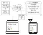
도 1과 도 2는 본 발명의 실시 예에 따른 태양광 발전 관리 시스템의 전체적인 네트워크 연결도를 나타낸 것이다.FIG. 1 and FIG. 2 show a whole network connection diagram of a solar power generation management system according to an embodiment of the present invention.
도 1과 도 2에 도시된 바와 같이, 본 발명에 따른 태양광 발전 관리 시스템은 태양광 발전 구조물에 설치되어 태양광 발전 구조물의 상태를 측정하는 센서부(100)와, 상기 센서부(100)를 통하여 측정된 데이터를 수집하고 분석하는 관리서버(200)를 포함하여 이루어진다.1 and 2, a solar power generation management system according to the present invention includes a
상기 센서부(100)에는 복수의 센서가 구비되는데, 이 센서들은 태양광 발전 구조물에 각각 설치되어 태양광 발전 구조물의 상태를 측정한 후 이를 원격에 위치한 관리서버(200)에 전송하게 된다.The
상기 관리서버(200)는 센서부(100)에서 측정된 데이터를 요청하여 수집하고 관리하며, 수집되는 태양광 발전 구조물의 상태 정보를 분석하여 구조물의 현재 상태와 수명 등을 예측하게 된다. 상기 관리서버(200)에 의해 분석되는 태양광 발전 구조물의 현재 상태 및 수명 예측 정보는 웹 서비스를 통해 시각화되어 인터넷 등의 통신망을 통해 관리자 단말기(300) 및 사용자 단말기(400)에 제공된다. 관리자 및 사용자는 원격에서 자신이 소지한 PC나 태블릿 PC, 스마트폰 등의 단말기를 사용하여 관리서버(200)에 접속한 후 태양광 발전 구조물의 상태를 실시간으로 확인할 수 있으며, 이상이 예측되는 경우 해당 태양광 발전 구조물로 이동하여 신속하게 조치를 취할 수 있다.The
다음의 표 1은 본 발명의 실시 예에 따른 센서부(100)를 통하여 측정되는 태양광 발전 구조물의 상태 정보 일례를 나타낸 것이다.The following Table 1 shows an example of status information of the solar power generation structure measured through the

표 1에 표시된 상태 정보는 센서부(100)에 구비된 센서들을 통하여 측정되는데, 수평 일사량 센서는 구조물에 전달되는 태양광의 양을 확인하는 센서로서 이를 통하여 현재 구조물이 있는 지역의 날씨를 예측한다. 경사 일사량 센서는 실제 구조물과 같은 각도로 구조물에 설치되어서 태양광 패널이 받는 일사량을 측정하는데, 이를 통하여 태양광 패널의 발전량을 예측한다.The state information shown in Table 1 is measured through the sensors provided in the
한편, 일사량만 측정할 경우 여름철에 일사량이 많은데 반해 발전이 되지 않는 경우 확인이 불가능한데, 이를 대비하여 본 발명에서는 태양광 패널의 온도를 측정할 수 있는 구조물 온도센서를 장착하여 태양광 발전의 효율을 예측하는 기능을 수행하는 한편, 이산화탄소(CO2) 센서와 함께 구조물 주변의 화재발생 여부를 확인할 수 있도록 하였다. 대기 온도 센서도 수평 일사량 센서와 마찬가지로 현재 태양광 구조물이 설치된 위치의 온도를 측정하는데 사용된다. 또한, 기울기 센서를 통하여 구조물의 X축, Y축, Z축에 대한 움직임을 측정하여 구조물의 수명 예측에 사용하게 된다. 이외에도, 전류센서나 전압센서를 통하여 구조물의 각 위치별 전류값 및 전압값을 측정함으로써 구조물의 수명을 예측하는데 사용할 수 있다.On the other hand, when the solar radiation amount is measured, it can not be confirmed when the solar radiation amount is large in summer but can not be generated. In contrast, in the present invention, by installing a structure temperature sensor capable of measuring the solar panel temperature, (CO2 ) sensor, and to detect the occurrence of fire in the vicinity of the structure. The atmospheric temperature sensor is also used to measure the temperature at the location where the solar photovoltaic structure is installed, like the horizontal radiation sensor. Also, it is used to predict the life of the structure by measuring the movement of the structure with respect to the X axis, Y axis, and Z axis through the tilt sensor. In addition, it can be used to predict the lifetime of a structure by measuring the current value and the voltage value for each position of the structure through a current sensor or a voltage sensor.
상기와 같이 태양광 발전 구조물의 상태 정보를 측정하는 센서부(100)에는 MCU 및 통신모듈이 구비되어, 각 센서를 통하여 측정되는 데이터를 통신 규격에 맞게 패킷화하여 유선 또는 무선 통신을 통해 관리서버(200)로 전송하게 된다. 상기 센서부(100)는 관리서버(200)의 요청에 따라 또는 주기적으로 측정 데이터를 관리서버(200)에 전송하게 된다.The
도 3은 본 발명의 실시 예에 따른 관리서버의 블록 구성도를 나타낸 것이다.3 is a block diagram of a management server according to an embodiment of the present invention.
도 3에 도시된 바와 같이, 본 발명에 따른 관리서버(200)는 데이터 입력 및 표시를 위한 입력부(220) 및 출력부(230)와, 네트워크망을 통하여 외부의 컴퓨터 시스템과 통신을 수행하는 통신부(240)와, 외부 주변장치와의 데이터 송수신을 위한 인터페이스부(250)와, 센서부(100)로부터 센서 측정값을 제공받아 태양광 발전 구조물을 관리하는 태양광 발전 구조물 관리부(260)와, 관리서버(200)에 의해 처리되는 데이터가 등록되는 데이터베이스(270)와, 상기 각 구성부의 동작을 제어하는 중앙제어부(210)를 포함하여 이루어진다.3, the
상기 중앙제어부(210)는 관리서버(200)의 각 구성부를 제어하고 관리하는 장치로서, 이 중앙제어부(210)에는 통상의 중앙처리장치(CPU), 램(RAM), 롬(ROM) 등의 하드웨어 장치와 상기 하드웨어 장치를 인식하여 구동하는 소프트웨어가 구비되어 관리서버(200)의 전체적인 동작을 제어하게 된다.The
상기 태양광 발전 구조물 관리부(260)에는 센서부(100)를 통하여 측정되는 센서 측정값을 전송받아 데이터베이스(270)에 등록하고 관리하는 센서 측정값 수집모듈(261)과, 상기 센서 측정값 수집모듈(261)을 통하여 수집된 센서 측정값을 분석하여 태양광 발전 구조물의 상태를 진단하는 구조물 상태 진단모듈(262)과, 상기 센서 측정값 수집모듈(261)을 통하여 수집된 센서 측정값을 분석하여 태양광 발전 구조물의 수명을 예측하는 구조물 수명 예측모듈(263)과, 상기 구조물 수명 예측모듈(263)의 예측 결과 예상되는 수명이 단축된 경우 해당 태양광 발전 구조물의 구조를 변경하도록 조치 또는 안내하는 구조물 변경 관리모듈(264)과, 상기 태양광 발전 구조물 관리부(260)를 통하여 처리되는 데이터를 통신망을 통하여 연결된 관리자 단말기(300) 또는 사용자 단말기(400)에 시각화하여 제공하는 시각화 모듈(265)이 구비된다.The solar power generation
이하에서는 상기의 구성으로 이루어진 태양광 발전 관리 시스템을 통하여 태양광 발전 구조물이 관리되는 과정에 대하여 상세히 설명하기로 한다.Hereinafter, the process of managing the solar power generation structure through the solar power generation management system having the above-described configuration will be described in detail.
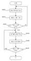
도 4는 본 발명의 실시 예에 따라 센서부를 통하여 수집되는 데이터가 관리서버로 전송되어 저장되는 과정을 나타낸 흐름도이다.4 is a flowchart illustrating a process in which data collected through a sensor unit is transmitted to a management server and stored according to an embodiment of the present invention.
도 4에 도시된 바와 같이, 동작이 시작되면 관리서버(200)의 센서 측정값 수집모듈(261)은 센서부(100)에 측정된 데이터를 전송하라는 요청 신호(#1NQ110000$)를 전송하게 된다(S100). 관리서버(200)와 센서부(100)의 통신이 연결된 경우 센서부(100)는 요청 신호에 따라 측정된 센서 측정값을 관리서버(200)에 전송하고, 연결되지 않은 경우에는 다시 데이터 전송 요청 단계로 돌아가서 요청을 기다리게 된다(S110). 도 5는 관리서버(200)의 센서 측정값 수집모듈(261)에서 센서부(100)에 센서 측정값을 요청하는 패킷 구성의 일례를 나타낸 것이다.4, when the operation is started, the sensor measurement
상기 센서부(100)와 관리서버(200)의 통신이 연결되어 센서부(100)의 측정 데이터가 관리서버(200)에 입력되면(S120), 관리서버(200)의 센서 측정값 수집모듈(261)은 입력된 센서 측정값을 데이터베이스(270)에 저장하게 된다(S130). 본 발명의 실시 예에서는 센서 측정값 수집모듈(261)에서 데이터베이스(270)에 저장된 센서 측정값의 헤더 부분을 검사하여 헤더 값(#1NR11)이 존재하는 경우 수신된 센서 측정값이 올바르다고 판단하여(S140), 데이터를 분할하고(S150), 이를 데이터베이스(270)에 저장하게 된다(S160). 이에 반해, 헤더 부분이 다른 경우, 전송에 오류가 있다고 판단하여 데이터베이스(270)에 저장하지 않고 다시 데이터 전송 요청 단계로 돌아가게 된다.When the
도 6은 본 발명의 실시 예에 따라 센서부에서 관리서버에 전송하는 센서 측정값 패킷 구성의 일례를 나타낸 것이다.6 shows an example of a configuration of a sensor measurement value packet transmitted from a sensor unit to a management server according to an embodiment of the present invention.
도 6에 도시된 바와 같이, 센서부(100)에서 관리서버(200)로 전송하는 센서 측정값 패킷에는 패킷의 유효성을 판단하기 위한 헤드 부분(#1NR11)과, 측정값 데이터(DATA)가 포함되는데, 측정값 데이터(DATA)에는 센서부(100)에 구비된 각 센서를 통하여 측정된 수평 일사량(수평 일사), 경사 일사량(경사 일사), 구조물 온도(모듈 온도), 대기 온도(주위 온도), X축/Y축/Z축 기울기(중력 X, Y, Z), 이산화탄소 농도(CO2), 각 위치별 전류값(전류 A, B, C) 등이 포함된다.6, the sensor measurement value packet transmitted from the
본 발명의 실시 예에서 센서부(100)는 각 센서를 통하여 측정된 정보를 16진수 데이터로 변환하여 관리서버(200)에 전송하게 되는데, 관리서버(200)의 센서 측정값 수집모듈(261)에서는 수신받은 16진수 데이터를 다시 10진수로 변환한 후 각각의 정보 단위로 패킷을 분할하여 데이터베이스(270)에 저장하게 된다. 이후에도 센서 측정값 수집모듈(261)은 수신받은 정보를 데이터베이스(270)에 계속 저장하게 되는데, 도 7은 데이터베이스(270)에 저장되는 DB 테이블 구조의 일례를 나타낸 것이다.In the embodiment of the present invention, the
도 7에 도시된 바와 같이, 관리서버(200)의 데이터베이스(270)는 2개의 테이블로 구성되는데, 첫 번째 테이블은 센서부(100)를 통하여 측정된 데이터를 30초 간격으로 제공받아 저장하는 수신테이블이다. 한편, 저장된 데이터는 시각화하여 활용할 수 있어야 하는데, 30초마다 갱신할 경우 시각화하는데 부담이 되기 때문에 본 발명에서는 1시간마다 그 값의 평균값을 계산하여 이용하게 되며, 이때 평균값을 두 번째 평균테이블에 저장하게 된다.As shown in FIG. 7, the
관리서버(200)의 시각화 모듈(265)은 데이터베이스(270) 내 평균테이블에 저장되는 정보를 구조물 관리자와 사용자가 통신망을 통하여 어디서나 확인할 수 있도록 웹 서비스를 통하여 제공하게 된다. 도 8은 본 발명의 실시 예에 따른 관리서버(200)의 웹 서비스 실행 과정을 나타낸 개념도로서, 관리서버(200)의 시각화 모듈(265)은 데이터베이스(270)에 등록된 태양광 발전 구조물 상태 정보를 실시간 모니터링 홈페이지 양식으로 관리자 단말기(300) 또는 사용자 단말기(400)에 제공하게 된다.The
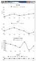
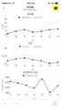
도 9는 관리자 또는 사용자가 데스크탑 PC를 이용하여 태양광 발전 구조물 상태 정보 웹 서비스를 제공받는 화면 일례이고, 도 10은 모바일 단말기를 이용하여 태양광 발전 구조물 상태 정보 웹 서비스를 제공받는 화면 일례를 나타낸 것으로, 관리자 또는 사용자는 접속하는 단말기의 종류와 관계없이 동일한 정보에 대한 접근이 가능하다.FIG. 9 shows an example of a screen in which a manager or a user is provided with a PV system status information web service using a desktop PC, and FIG. 10 shows an exemplary screen in which a PV system status information web service is provided using a mobile terminal The manager or the user can access the same information regardless of the type of the terminal to be connected.
한편, 본 발명에 따른 태양광 발전 관리 시스템은 센서부(100)를 통하여 측정되는 태양광 발전 구조물의 정보를 제공할 뿐 아니라, 구조물의 상태를 진단하고 수명을 예측하여 구조물의 상태를 변경할 수 있도록 한다.Meanwhile, the solar power generation management system according to the present invention not only provides information of the solar power generation structure measured through the
도 11은 본 발명의 실시 예에 따른 태양광 발전 관리 시스템을 통하여 태양광 발전 구조물의 상태가 진단되는 과정을 나타낸 흐름도이다.11 is a flowchart illustrating a process of diagnosing the state of a solar power generation structure through a solar power generation management system according to an embodiment of the present invention.
단계 S200, S210, S230 : 관리서버(200)의 구조물 상태 진단모듈(262)은 센서부(100)로부터 센서 측정값이 수신되면(S200), 동일 센서에 대해 이전에 수신되었던 센서 측정값과 현재 수신된 센서 측정값을 비교하여(S210), 변화가 있는 경우 변화량을 계산하게 된다(S230). 만약, 이전 측정값과 현재 측정값에 변화가 없다면 센서 측정값을 수신하여 이전 값과 비교하는 과정을 반복하여 수행하게 된다.The structure
단계 S220, S221 : 만약, 변화량이 안전 기준 값보다 작은 경우(S220), 해당 구조물은 안전한 것으로 진단하게 된다(S221). 여기에서 안전 기준 값은 센서의 오차 등을 고려하여 태양광 발전 구조물의 안전에 영향을 미치지 않는 값으로 설정된다.Steps S220 and S221: If the change amount is smaller than the safety reference value (S220), the structure is diagnosed as being safe (S221). In this case, the safety reference value is set to a value that does not affect the safety of the photovoltaic power generation structure in consideration of the error of the sensor.
단계 S230, S231 : 또한, 변화량이 안전 기준 값보다 크고 경고 기준 값보다 작은 경우, 해당 구조물은 경고 수준인 것으로 진단하게 된다(S231). 여기에서 경고 기준 값은 현재 위험하지는 않지만 현 상태가 장시간 지속되는 경우 향후 문제가 발생할 수 있는 정도의 경고 수준으로 설정된다.Steps S230 and S231: If the amount of change is larger than the safety reference value and smaller than the warning reference value, the structure is diagnosed as a warning level (S231). Here, the warning reference value is set to an alarm level that is not currently dangerous but can cause future problems if the current state lasts for a long time.
단계 S240 : 한편, 변화량이 경고 기준 값보다 크다면, 해당 태양광 발전 구조물의 현재 상태가 위험한 것으로 진단하게 된다.Step S240: If the amount of change is larger than the warning reference value, the current state of the photovoltaic generation structure is diagnosed as dangerous.
단계 S250 : 상기 과정에서 진단되는 태양광 발전 구조물의 상태 정보(안전, 경고, 위험)는 웹 서비스를 통하여 해당 구조물의 관리자 또는 사용자에게 제공될 수 있으며, 경고 또는 위험으로 진단되는 경우 해당 관리자 및 사용자의 스마트 폰 등의 휴대 단말기에 즉시 전송하여 이를 알려주게 된다.Step S250: The status information (safety, warning, and risk) of the photovoltaic power generation structure diagnosed in the above process can be provided to the administrator or user of the structure through the web service. If the warning or danger is diagnosed, Such as a smart phone, and informs the user of it.
도 12는 본 발명의 실시 예에 따른 태양광 발전 관리 시스템을 통하여 태양광 발전 구조물의 수명을 예측하여 위험 상태를 해결하는 과정을 나타낸 흐름도이다.FIG. 12 is a flowchart illustrating a process for predicting the lifetime of a photovoltaic power generation structure through a solar power generation management system according to an embodiment of the present invention and solving the risk state.
단계 S300, S310 : 관리서버(200)의 구조물 수명 예측모듈(263)은 센서부(100)로부터 센서 측정값이 수신되면(S300), 수신된 센서 측정값을 분석하여 해당 구조물의 예상 수명을 측정하게 된다(S310). 태양광 발전 구조물의 예상 수명은 해당 구조물의 평균인 기준 예상 수명을 기준으로, 센서부(100)를 통하여 측정되는 구조물의 움직임(즉, X축, Y축, Z축에 대한 기울기 정보), 주변 날씨, 발전량, 전류값 및 전압값 등을 통하여 예측된다.Steps S300 and S310: The structure
단계 S320, S330, S340 : 구조물의 예상 수명 예측 결과, 예측된 예상 수명이 기준 예상 수명보다 단축된 경우(S320), 구조물 변경 관리모듈(264)을 통하여 해당 구조물의 비정상적인 부분을 정상적인 상태로 변경하고(S330), 다시 예상 수명을 예측하게 된다(S340). 여기에서, 상기 구조물 변경 관리모듈(264)은 예상 수명이 단축된 경우, 관리자 또는 사용자에게 통보하여 해당 태양광 발전 구조물을 보수하도록 안내할 수 있으며, 태양광 발전 구조물의 원격 제어가 가능한 경우 수명 단축 원인 되는 구조물을 직접 제어하여 보수할 수도 있다.If the predicted life expectancy of the structure is shorter than the expected life expectancy (S320), the structure
단계 S350 : 예상 수명을 다시 예측한 결과, 그래도 예상 수명이 평균 예상 수명보다 단축된 경우 구조물의 상태를 변경하는 과정을 반복하여 수행하게 된다. 만약, 예측된 예상 수명이 평균 예상 수명을 만족하는 경우 위험 상태 해결 과정이 종료된다.Step S350: If the estimated life expectancy is predicted again, if the estimated life expectancy is shorter than the average expected life, the process of changing the state of the structure is repeatedly performed. If the expected life expectancy satisfies the average life expectancy, the risk state resolution process ends.
이와 같이, 본 발명에 따른 태양광 발전 관리 시스템은 태양광 발전 구조물에 설치된 센서를 통하여 구조물의 상태 정보를 측정하고, 원격의 관리서버(200)에서 센서 측정값을 전송받아 분석함으로써 태양광 발전 구조물의 상태와 수명을 예측하며, 예측된 태양광 발전 구조물의 상태 및 예측 결과를 웹 서비스를 통해 관리자 및 사용자에게 제공하게 된다.As described above, the solar power generation management system according to the present invention measures the state information of the structure through the sensor installed in the solar power generating structure, receives the sensor measurement value from the
이러한 본 발명은 상술한 실시 예에 한정되는 것은 아니며 본 발명이 속하는 기술 분야에서 통상의 지식을 갖는 자에 의해 본 발명의 기술사상과 아래에 기재될 특허청구 범위의 균등범위 내에서 다양한 수정 및 변형이 이루어질 수 있음은 물론이다.It is to be understood that the present invention is not limited to the above-described embodiment, and that various modifications and changes may be made by those skilled in the art without departing from the spirit and scope of the appended claims. Of course, can be achieved.
100 : 센서부
200 : 관리서버 210 : 중앙제어부
220 : 입력부 230 : 출력부
240 : 통신부 250 : 인터페이스부
260 : 태양광 발전 구조물 관리부 261 : 센서 측정값 수집모듈
262 : 구조물 상태 진단모듈 263 : 구조물 수명 예측모듈
264 : 구조물 변경 관리모듈 265 : 시각화 모듈
270 : 데이터베이스
300 : 관리자 단말기
400 : 사용자 단말기(400)100:
200: management server 210: central control unit
220: input unit 230: output unit
240: communication unit 250: interface unit
260: Solar power generation structure management unit 261: Sensor measurement value acquisition module
262: Structure condition diagnosis module 263: Structure life prediction module
264: Structure change management module 265: Visualization module
270: Database
300: administrator terminal
400:
Claims (7)
Translated fromKorean상기 구조물 상태 진단모듈(262)은 센서 측정값 수집모듈(261)을 통하여 현재 수집된 센서 측정값을 이전에 수신되었던 센서 측정값과 비교하여 변화량을 계산하고, 상기 변화량이 설정된 안전 기준 값보다 작은 경우 해당 태양광 발전 구조물을 안전한 것으로 진단하고, 상기 변화량이 안전 기준 값보다 크고 설정된 경고 기준 값보다 작은 경우 해당 태양광 발전 구조물을 경고 수준으로 진단하며, 상기 변화량이 경고 기준 값보다 큰 경우 해당 태양광 발전 구조물의 현재 상태가 위험한 것으로 진단하며,
상기 구조물 수명 예측모듈(263)은 센서 측정값 수집모듈(261)을 통하여 수집된 센서 측정값을 분석하여 해당 태양광 발전 구조물의 수명을 예측하되, 예측된 수명이 설정된 기준 예상 수명보다 단축된 경우, 구조물 변경 관리모듈(264)을 통하여 수명이 단축된 구조물의 상태를 변경한 후, 다시 측정된 센서 측정값을 분석하여 수명을 다시 예측하는 것을 특징으로 하는 태양광 발전 관리 시스템.
It is installed in the solar power generation structure and installed horizontal solar radiation sensor to measure horizontal radiation dose, oblique solar radiation sensor to measure slope solar radiation amount, carbon dioxide concentration sensor to measure carbon dioxide concentration, structure temperature sensor to measure temperature of structure, A sensor unit 100 having an atmospheric temperature sensor for measuring the atmospheric temperature of the area, a tilt sensor for measuring the tilt of the X axis, the Y axis, and the Z axis of the structure; A sensor measurement value collection module 261 for receiving the sensor measurement values measured through the sensor unit 100 and registering the sensor measurement values in the database 270, a sensor measurement value collection module 261 for analyzing the sensor measurement values collected through the sensor measurement value collection module 261, A structure state diagnosis module 262 for diagnosing the state of the photovoltaic power generation structure, a structural life prediction module 263 for analyzing sensor measurement values collected through the sensor measurement value acquisition module 261, A management server 200 having a visualization module 265 for visualizing the obtained sensor measurement value, structure state diagnosis information, and structure life prediction information through a communication network to the administrator or the user terminal 400; The solar power generation management system comprising:
The structure state diagnosis module 262 compares the currently measured sensor measurement value with the previously measured sensor measurement value through the sensor measurement value acquisition module 261, and calculates the change amount when the change amount is smaller than the set safety reference value If the amount of change is greater than the safety reference value and less than the established warning reference value, the solar power generation structure is diagnosed as a warning level. If the amount of change is greater than the warning reference value, The present state of photovoltaic structures is diagnosed as dangerous,
The structure life prediction module 263 analyzes the sensor measurement values collected through the sensor measurement value acquisition module 261 to estimate the life of the solar power generation structure. If the estimated life span is shorter than the reference life expectancy The structure change management module 264 changes the state of the structure whose life is shortened, and then analyzes the measured sensor measurement value again to predict the life span again.
상기 센서 측정값 수집모듈(261)이 센서부(100)에 센서 측정값을 전송하라는 요청 신호를 전송하면, 상기 센서부(100)는 측정된 센서 측정값을 패킷 데이터로 센서 측정값 수집모듈(261)로 전송하고,
상기 센서 측정값 수집모듈(261)은 수신되는 센서 측정값 패킷 데이터의 헤더를 검사하여 센서 측정값이 올바른지 인증을 수행하고, 인증된 센서 측정값 패킷 데이터를 각각 정보 단위의 패킷으로 분할하여 데이터베이스(270)에 저장하는 것을 특징으로 하는 태양광 발전 관리 시스템.
The method according to claim 1,
When the sensor measurement value acquisition module 261 transmits a request signal to transmit the sensor measurement value to the sensor unit 100, the sensor unit 100 transmits the measured sensor measurement value as packet data to the sensor measurement value acquisition module 261,
The sensor measurement value acquisition module 261 checks the header of the received sensor measurement value packet data to verify whether the sensor measurement value is correct, divides the authenticated sensor measurement value packet data into individual information unit packets, 270). ≪ / RTI >
상기 센서 측정값 수집모듈(261)은 설정된 시간마다 데이터베이스(270)에 등록된 센서 측정값의 평균을 계산하여 평균 테이블로 데이터베이스(270)에 저장하고,
상기 시각화 모듈(265)은 상기 평균 테이블에 저장된 센서 측정값을 시각화하여 통신망을 통해 관리자 또는 사용자 단말기(400)에 웹 서비스로 제공하는 것을 특징으로 하는 태양광 발전 관리 시스템.The method according to claim 1,
The sensor measurement value acquisition module 261 calculates an average of the sensor measurement values registered in the database 270 at predetermined time intervals, stores the average of the sensor measurement values in the database 270 as an average table,
Wherein the visualization module (265) visualizes the sensor measurement values stored in the average table and provides the sensor measurement values to the administrator or the user terminal (400) through a communication network as a web service.
Priority Applications (1)
| Application Number | Priority Date | Filing Date | Title |
|---|---|---|---|
| KR1020170051844AKR101910892B1 (en) | 2017-04-21 | 2017-04-21 | IoT based Mobile Smart Solar Power Generation Management System |
Applications Claiming Priority (1)
| Application Number | Priority Date | Filing Date | Title |
|---|---|---|---|
| KR1020170051844AKR101910892B1 (en) | 2017-04-21 | 2017-04-21 | IoT based Mobile Smart Solar Power Generation Management System |
Publications (1)
| Publication Number | Publication Date |
|---|---|
| KR101910892B1true KR101910892B1 (en) | 2018-10-24 |
Family
ID=64132493
Family Applications (1)
| Application Number | Title | Priority Date | Filing Date |
|---|---|---|---|
| KR1020170051844AActiveKR101910892B1 (en) | 2017-04-21 | 2017-04-21 | IoT based Mobile Smart Solar Power Generation Management System |
Country Status (1)
| Country | Link |
|---|---|
| KR (1) | KR101910892B1 (en) |
Cited By (5)
| Publication number | Priority date | Publication date | Assignee | Title |
|---|---|---|---|---|
| KR102023465B1 (en)* | 2019-02-12 | 2019-09-20 | 강남욱 | Defect diagnosis system and the method of photovoltaic power generation equipment using Internet of Things |
| KR20200124865A (en)* | 2019-04-25 | 2020-11-04 | 현대자동차주식회사 | Power tail gate system for vehicle and method of controlling the same |
| KR20200135078A (en) | 2019-05-24 | 2020-12-02 | 홍익대학교세종캠퍼스산학협력단 | System for predicting present state and future state of agriculture solar power generation structure based on rnn |
| KR20210115432A (en)* | 2020-03-13 | 2021-09-27 | 태웅이엔에스 주식회사 | Operation and management system of photovoltaic power plant and method thereof |
| KR20220092628A (en)* | 2019-11-14 | 2022-07-01 | 엔비전 디지털 인터내셔널 피티이 리미티드 | Solar power curve modeling method and apparatus, and computer device and storage medium |
Citations (1)
| Publication number | Priority date | Publication date | Assignee | Title |
|---|---|---|---|---|
| KR101565895B1 (en)* | 2015-01-09 | 2015-11-04 | 한국기술교육대학교 산학협력단 | System for remote photovoltaic monitoring system and the monitoring method thereof |
- 2017
- 2017-04-21KRKR1020170051844Apatent/KR101910892B1/enactiveActive
Patent Citations (1)
| Publication number | Priority date | Publication date | Assignee | Title |
|---|---|---|---|---|
| KR101565895B1 (en)* | 2015-01-09 | 2015-11-04 | 한국기술교육대학교 산학협력단 | System for remote photovoltaic monitoring system and the monitoring method thereof |
Cited By (9)
| Publication number | Priority date | Publication date | Assignee | Title |
|---|---|---|---|---|
| KR102023465B1 (en)* | 2019-02-12 | 2019-09-20 | 강남욱 | Defect diagnosis system and the method of photovoltaic power generation equipment using Internet of Things |
| KR20200124865A (en)* | 2019-04-25 | 2020-11-04 | 현대자동차주식회사 | Power tail gate system for vehicle and method of controlling the same |
| KR102770453B1 (en)* | 2019-04-25 | 2025-02-20 | 현대자동차주식회사 | Power tail gate system for vehicle and method of controlling the same |
| KR20200135078A (en) | 2019-05-24 | 2020-12-02 | 홍익대학교세종캠퍼스산학협력단 | System for predicting present state and future state of agriculture solar power generation structure based on rnn |
| KR102267811B1 (en)* | 2019-05-24 | 2021-06-22 | 홍익대학교세종캠퍼스산학협력단 | System for predicting present state and future state of agriculture solar power generation structure based on rnn |
| KR20220092628A (en)* | 2019-11-14 | 2022-07-01 | 엔비전 디지털 인터내셔널 피티이 리미티드 | Solar power curve modeling method and apparatus, and computer device and storage medium |
| KR102481611B1 (en)* | 2019-11-14 | 2022-12-27 | 엔비전 디지털 인터내셔널 피티이 리미티드 | Solar power curve modeling method and apparatus, and computer device and storage medium |
| KR20210115432A (en)* | 2020-03-13 | 2021-09-27 | 태웅이엔에스 주식회사 | Operation and management system of photovoltaic power plant and method thereof |
| KR102347238B1 (en)* | 2020-03-13 | 2022-01-04 | 태웅이엔에스 주식회사 | Operation and management system of photovoltaic power plant and method thereof |
Similar Documents
| Publication | Publication Date | Title |
|---|---|---|
| KR101910892B1 (en) | IoT based Mobile Smart Solar Power Generation Management System | |
| ES2987306T3 (en) | System and method for evaluating predictive failure models of renewable energy assets | |
| KR102267811B1 (en) | System for predicting present state and future state of agriculture solar power generation structure based on rnn | |
| CN113847216B (en) | Fan blade state prediction method, device, equipment and storage medium | |
| KR101989962B1 (en) | Integrated management server and building management system using the same | |
| EP2804382A1 (en) | Reliability determination of camera fault detection tests | |
| CN117909703B (en) | Data quality evaluation method and system based on alarm threshold trigger | |
| CN114169692A (en) | A system, method, electronic device and medium for dealing with equipment hidden dangers | |
| JP2007183166A (en) | Utility pole stress evaluator, utility pole stress evaluation system, utility pole stress evaluation method, and utility pole | |
| KR20140109596A (en) | Apparatus method for predicting and correcting meter reading data in a range not reading | |
| KR101457643B1 (en) | The system for diagnostic of photovoltaic generating facilities | |
| CN115469178A (en) | Transmission line monitoring method, device, computer equipment, storage medium | |
| US11782899B2 (en) | System and method for electronic document issuing using blockchain and computer program for the same | |
| CN119223189A (en) | A deformation monitoring system and method for dam surface | |
| CN118960825A (en) | A method and system for collecting and transmitting on-site monitoring data of new energy stations | |
| CN116952423A (en) | Metal structure stress monitoring system, method, device, equipment and medium | |
| CN114530880B (en) | Power grid regional load prediction system and method based on big data | |
| CN215832753U (en) | Monitoring system | |
| KR100931021B1 (en) | Track monitoring diagnosis device with insulator defect determination module | |
| KR20230036880A (en) | A system for monitoring solar power generation sites based on thermal image | |
| CN113267216A (en) | Monitoring system and monitoring method | |
| KR20220124853A (en) | Apparatus and method for inspection of solar module | |
| CN113449689A (en) | Communication tower remote monitoring method based on Internet of things platform | |
| KR101996063B1 (en) | USER CUSTOMIZED MONITORING SYSTEM OF SOLAR POWER GENERATION STRUCTURE BASED ON IoT | |
| ES2644966B1 (en) | System and method of detection and prediction of the evolution of forest fires. |
Legal Events
| Date | Code | Title | Description |
|---|---|---|---|
| PA0109 | Patent application | St.27 status event code:A-0-1-A10-A12-nap-PA0109 | |
| PA0201 | Request for examination | St.27 status event code:A-1-2-D10-D11-exm-PA0201 | |
| PE0902 | Notice of grounds for rejection | St.27 status event code:A-1-2-D10-D21-exm-PE0902 | |
| E13-X000 | Pre-grant limitation requested | St.27 status event code:A-2-3-E10-E13-lim-X000 | |
| P11-X000 | Amendment of application requested | St.27 status event code:A-2-2-P10-P11-nap-X000 | |
| P13-X000 | Application amended | St.27 status event code:A-2-2-P10-P13-nap-X000 | |
| PN2301 | Change of applicant | St.27 status event code:A-3-3-R10-R13-asn-PN2301 St.27 status event code:A-3-3-R10-R11-asn-PN2301 | |
| E701 | Decision to grant or registration of patent right | ||
| PE0701 | Decision of registration | St.27 status event code:A-1-2-D10-D22-exm-PE0701 | |
| GRNT | Written decision to grant | ||
| PR0701 | Registration of establishment | St.27 status event code:A-2-4-F10-F11-exm-PR0701 | |
| PR1002 | Payment of registration fee | St.27 status event code:A-2-2-U10-U11-oth-PR1002 Fee payment year number:1 | |
| PG1601 | Publication of registration | St.27 status event code:A-4-4-Q10-Q13-nap-PG1601 | |
| R18-X000 | Changes to party contact information recorded | St.27 status event code:A-5-5-R10-R18-oth-X000 | |
| PR1001 | Payment of annual fee | St.27 status event code:A-4-4-U10-U11-oth-PR1001 Fee payment year number:4 | |
| R18-X000 | Changes to party contact information recorded | St.27 status event code:A-5-5-R10-R18-oth-X000 | |
| PR1001 | Payment of annual fee | St.27 status event code:A-4-4-U10-U11-oth-PR1001 Fee payment year number:5 | |
| PR1001 | Payment of annual fee | St.27 status event code:A-4-4-U10-U11-oth-PR1001 Fee payment year number:6 | |
| PR1001 | Payment of annual fee | St.27 status event code:A-4-4-U10-U11-oth-PR1001 Fee payment year number:7 | |
| PR1001 | Payment of annual fee | St.27 status event code:A-4-4-U10-U11-oth-PR1001 Fee payment year number:8 |