KR101910800B1 - Apparatus for treating a substrate - Google Patents
Apparatus for treating a substrateDownload PDFInfo
- Publication number
- KR101910800B1 KR101910800B1KR1020170067012AKR20170067012AKR101910800B1KR 101910800 B1KR101910800 B1KR 101910800B1KR 1020170067012 AKR1020170067012 AKR 1020170067012AKR 20170067012 AKR20170067012 AKR 20170067012AKR 101910800 B1KR101910800 B1KR 101910800B1
- Authority
- KR
- South Korea
- Prior art keywords
- exhaust
- line
- processing unit
- substrate
- point
- Prior art date
- Legal status (The legal status is an assumption and is not a legal conclusion. Google has not performed a legal analysis and makes no representation as to the accuracy of the status listed.)
- Active
Links
Images


Classifications
- H—ELECTRICITY
- H01—ELECTRIC ELEMENTS
- H01L—SEMICONDUCTOR DEVICES NOT COVERED BY CLASS H10
- H01L21/00—Processes or apparatus adapted for the manufacture or treatment of semiconductor or solid state devices or of parts thereof
- H01L21/67—Apparatus specially adapted for handling semiconductor or electric solid state devices during manufacture or treatment thereof; Apparatus specially adapted for handling wafers during manufacture or treatment of semiconductor or electric solid state devices or components ; Apparatus not specifically provided for elsewhere
- H01L21/67005—Apparatus not specifically provided for elsewhere
- H01L21/67011—Apparatus for manufacture or treatment
- H01L21/67017—Apparatus for fluid treatment
- H—ELECTRICITY
- H01—ELECTRIC ELEMENTS
- H01L—SEMICONDUCTOR DEVICES NOT COVERED BY CLASS H10
- H01L21/00—Processes or apparatus adapted for the manufacture or treatment of semiconductor or solid state devices or of parts thereof
- H01L21/67—Apparatus specially adapted for handling semiconductor or electric solid state devices during manufacture or treatment thereof; Apparatus specially adapted for handling wafers during manufacture or treatment of semiconductor or electric solid state devices or components ; Apparatus not specifically provided for elsewhere
- H01L21/67005—Apparatus not specifically provided for elsewhere
- H01L21/67242—Apparatus for monitoring, sorting or marking
Landscapes
- Engineering & Computer Science (AREA)
- Physics & Mathematics (AREA)
- Condensed Matter Physics & Semiconductors (AREA)
- General Physics & Mathematics (AREA)
- Manufacturing & Machinery (AREA)
- Computer Hardware Design (AREA)
- Microelectronics & Electronic Packaging (AREA)
- Power Engineering (AREA)
- Exposure Of Semiconductors, Excluding Electron Or Ion Beam Exposure (AREA)
Abstract
Description
Translated fromKorean본 발명은 기판의 처리 분위기를 배기하는 장치에 관한 것이다.The present invention relates to an apparatus for evacuating a processing atmosphere of a substrate.
반도체 소자 및 평판표시패널의 제조를 위해 사진, 식각, 애싱, 박막 증착, 그리고 세정 공정 등 다양한 공정들이 수행된다. 이러한 공정들 중 사진 공정은 도포, 노광, 그리고 현상 단계를 순차적으로 수행한다. 도포 공정은 기판의 표면에 레지스트와 같은 감광액을 도포하는 공정이다. 노광 공정은 감광막이 형성된 기판 상에 회로 패턴을 노광하는 공정이다. 현상 공정에는 기판의 노광 처리된 영역을 선택적으로 현상하는 공정이다.Various processes such as photolithography, etching, ashing, thin film deposition, and cleaning processes are performed for manufacturing semiconductor devices and flat panel display panels. Among these processes, the photolithography process sequentially performs the application, exposure, and development steps. The coating step is a step of applying a photosensitive liquid such as a resist to the surface of the substrate. The exposure process is a process for exposing a circuit pattern on a substrate having a photosensitive film formed thereon. The developing step is a step of selectively developing the exposed region of the substrate.
각각의 공정들은 기판이 처리되는 공간의 분위기가 일정하게 유지되어야 한다. 특히 도포 공정은 기판 상에 액막을 형성하는 공정으로, 분위기에 따라 액막의 두께가 상이해질 수 있다. 이로 인해 도포 공정의 분위기는 이와 다른 공정에 비해 더 주의를 요한다.Each of the processes must maintain a constant atmosphere of the space in which the substrate is processed. Particularly, the application step is a step of forming a liquid film on the substrate, and the thickness of the liquid film may be different depending on the atmosphere. As a result, the atmosphere of the application process requires more attention than other processes.
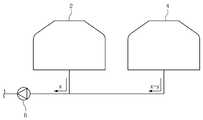
일반적으로 기판 처리 효율을 높이기 위해, 도포 공정을 수행하는 도포 유닛들은 복수 개로 제공되며, 공간 효율을 위해 도포 유닛들은 단일의 감압 부재에 의해 배기된다. 도 1은 일반적은 기판 처리 장치를 보여주는 단면도이다. 도 1을 참조하면, 제1유닛(2)과 제2유닛(4)은 각각 배기 라인에 의해 감압 부재(6)에 연결된다. 감압 부재(6)는 이에 연결된 유닛들(2,4)의 개수에 대응되는 배기력을 발생시켜, 복수 개의 공정 유닛들(2,4)을 균일하게 배기해야한다.Generally, in order to increase the substrate processing efficiency, a plurality of application units for performing the application process are provided, and for space efficiency, the application units are exhausted by a single pressure-sensitive member. 1 is a sectional view showing a general substrate processing apparatus. Referring to Fig. 1, the
그러나 공정 유닛들(2,4)은 그 위치에 따라 감압 부재(6)에 인접하게 위치되거나 멀게 위치된다. 즉, 공정 유닛들(2,4) 각각은 감압 부재(6)의 거리가 상이하다. 이로 인해 감압 부재(6)에 가깝게 위치되는 공정 유닛(2)일수록 높은 배기력이 제공되는 반면, 감압 부재(6)에 멀게 위치되는 공정 유닛(4)일수록 낮은 배기력이 제공된다. 따라서 공정 유닛(2,4)의 위치에 따라 기판 상에 형성된 액막의 두께는 상이하게 제공되며, 이는 공정 불량을 야기한다.However, the
본 발명은 복수 개의 공정 유닛들에 균일하게 배기할 수 있는 장치를 제공하고자 한다.The present invention intends to provide an apparatus capable of uniformly discharging a plurality of process units.
본 발명의 실시예는 기판의 처리 분위기를 배기하는 장치를 제공한다. 기판 처리 장치는 기판을 처리하는 제1공정 유닛, 기판을 처리하는 제2공정 유닛, 그리고 상기 제1공정 유닛 및 상기 제2공정 유닛을 배기하는 배기 어셈블리를 포함하되, 상기 배기 어셈블리는 메인 배기 라인, 상기 메인 배기 라인을 감압하는 감압 부재, 상기 메인 배기 라인으로부터 제1배기 지점에서 분기되어 상기 제1공정 유닛에 연결되는 제1배기 라인, 상기 메인 배기 라인으로부터 제2배기 지점에서 분기되어 상기 제2공정 유닛에 연결되는 제2배기 라인, 그리고 상기 메인 배기 라인에 연결되어 상기 메인 배기 라인에 가스를 보충하여 제공하는 보충 부재를 포함하되, 상기 제2배기 지점은 상기 제1배기 지점보다 상기 감압 부재로부터 더 멀리 제공된 위치이고, 상기 보충 부재는 상기 감압 부재에서 상기 제1배기 지점보다 멀리 떨어진 위치에서 상기 메인 배기 라인에 연결된다.An embodiment of the present invention provides an apparatus for evacuating a processing atmosphere of a substrate. The substrate processing apparatus includes a first processing unit for processing a substrate, a second processing unit for processing the substrate, and an exhaust assembly for exhausting the first processing unit and the second processing unit, the exhaust assembly including a main exhaust line A first exhaust line branched from the main exhaust line at a first exhaust point and connected to the first process unit, a second exhaust line branched from the main exhaust line at a second exhaust point, A second exhaust line connected to the first exhaust line, a second exhaust line connected to the second process unit, and a replenishing member connected to the main exhaust line to supplement and supply gas to the main exhaust line, And the replenishing member is located at a position farther from the first exhaust point in the pressure-reducing member Group is connected to the main exhaust line.
상기 보충 부재는 상기 메인 배기 라인의 제3배기 지점에 연결되며, 에어가 공급되는 보충 라인을 더 포함하되, 상기 제3배기 지점은 상기 메인 배기 라인의 길이 방향에 대해 상기 제2배기 지점을 기준으로 상기 제1배기 지점의 반대편에 위치될 수 있다. 상기 보충 부재는 상기 보충 라인에 에어를 블로우하는 팬을 포함하고, 상기 배기 어셈블리는 상기 제1공정 유닛 및 상기 제2공정 유닛 각각의 압력을 측정하는 측정 부재 및 상기 측정 부재로부터 측정된 압력들을 근거로 상기 팬을 제어하는 제어기를 더 포함할 수 있다.Wherein the supplemental member further includes a supplementary line connected to a third exhaust point of the main exhaust line and to which air is supplied, wherein the third exhaust point is connected to the second exhaust point with respect to the longitudinal direction of the main exhaust line The second exhaust point may be located opposite the first exhaust point. Wherein the supplemental member includes a fan blowing air to the supplemental line and the exhaust assembly includes a measuring member for measuring the pressure of each of the first processing unit and the second processing unit, And a controller for controlling the fan with the fan.
상기 장치는 상기 제1공정 유닛 및 상기 제2공정 유닛에 에어를 공급하는 에어 공급 유닛을 포함하되, 상기 보충 라인은 상기 에어 공급 유닛과 상기 제3배기 지점에 각각 연결될 수 있다. 상기 에어 공급 유닛은 메인 공급 라인, 상기 메인 공급 라인을 에어를 블로우하는 팬, 상기 메인 공급 라인으로부터 제1공급 지점에서 분기되어 상기 제1공정 유닛에 연결되는 제1공급 라인, 그리고 상기 메인 배기 라인으로부터 제2공급 지점에서 분기되어 상기 제2공정 유닛에 연결되는 제2공급 라인을 포함하되, 상기 제1공급 지점과 상기 제2공급 지점 중 어느 하나는 상기 팬으로부터 더 멀리 제공된 위치이고, 상기 보충 라인이 상기 메인 공급 라인에 연결되는 제3공급 지점은 상기 메인 공급 라인의 길이 방향에 대해 상기 어느 하나를 기준으로 다른 하나의 반대편에 위치될 수 있다. 상기 보충 부재는 상기 보충 라인의 에어 공급 유량을 조절하는 유량 조절 밸브를 더 포함하고, 상기 배기 어셈블리는 상기 제1공정 유닛 및 상기 제2공정 유닛 각각의 압력을 측정하는 측정 부재 및 상기 측정 부재로부터 측정된 압력들을 근거로 상기 유량 조절 밸브를 제어하는 제어기를 더 포함할 수 있다.The apparatus includes an air supply unit that supplies air to the first processing unit and the second processing unit, and the supplemental line may be connected to the air supply unit and the third exhaust point, respectively. The air supply unit includes a main supply line, a fan blowing air from the main supply line, a first supply line branched from the main supply line at a first supply point and connected to the first process unit, And a second supply line that is branched from a second supply point and is connected to the second process unit, wherein either the first supply point or the second supply point is a position further provided from the fan, A third supply point at which a line is connected to the main supply line may be located opposite to the other one of the plurality of supply lines in relation to the longitudinal direction of the main supply line. Wherein the supplemental member further comprises a flow control valve for regulating an air supply flow rate of the supplemental line, and the exhaust assembly includes a measuring member for measuring the pressure of each of the first processing unit and the second processing unit, And a controller for controlling the flow rate control valve based on the measured pressures.
상기 보충 부재는 상기 보충 라인으로부터 분기되어 에어를 배기시키는 보충 배기 라인 및 상기 보충 배기 라인을 개폐하는 배기 밸브를 더 포함하고, 상기 배기 어셈블리는 상기 제1공정 유닛 및 상기 제2공정 유닛 각각의 압력을 측정하는 측정 부재 및 상기 측정 부재로부터 측정된 압력들을 근거로 상기 배기 밸브를 제어하는 제어기를 더 포함할 수 있다.Wherein the supplemental member further includes a supplemental exhaust line branched from the supplemental line to exhaust air and an exhaust valve that opens and closes the supplemental exhaust line, wherein the exhaust assembly is configured to regulate the pressure of each of the first process unit and the second process unit And a controller for controlling the exhaust valve based on the measured pressures from the measuring member.
상기 제1공정 유닛 및 상기 제2공정 유닛은 동일한 기판 처리 공정을 수행할 수 있다.The first processing unit and the second processing unit may perform the same substrate processing process.
본 발명의 실시예에 의하면, 배기 편차가 발생된 공정 유닛에 대해 에어를 공급하여 공정 유닛들 간에 배기 편차를 최소화할 수 있다.According to the embodiment of the present invention, air can be supplied to a process unit in which an exhaust deviation is generated, thereby minimizing an exhaust deviation between process units.
또한 본 발명의 실시예에 의하면, 공정 유닛들에 공급되는 에어 중 잉여 에어를 배기 편차가 발생된 공정 유닛에 공급하여 공정 유닛들 간에 배기 편차를 최소화할 수 있다.Further, according to the embodiment of the present invention, surplus air among the air supplied to the process units can be supplied to the process unit in which the exhaust deviations are generated, thereby minimizing the exhaust deviations between the process units.
도 1은 일반적은 기판 처리 장치를 보여주는 단면도이다.
도 2는 본 발명의 실시예에 따른 기판 처리 설비의 평면도이다.
도 3은 도 2의 설비를 A-A 방향에서 바라본 단면도이다.
도 4는 도 2의 설비를 B-B 방향에서 바라본 단면도이다.
도 5는 도 2의 설비를 C-C 방향에서 바라본 단면도이다.
도 6은 도 2의 도포 유닛을 보여주는 단면도이다.
도 7은 도 6의 도포 유닛 및 배기 어셈블리를 보여주는 단면도이다.
도 8은 도 7의 배기 어셈블리의 다른 실시예를 보여주는 단면도이다.
도 9는 도 7의 배기 어셈블리의 또 다른 실시예를 보여주는 단면도이다.1 is a sectional view showing a general substrate processing apparatus.
2 is a top view of a substrate processing facility according to an embodiment of the present invention.
3 is a cross-sectional view of the facility of FIG. 2 viewed in the AA direction.
Fig. 4 is a cross-sectional view of the facility of Fig. 2 viewed from the BB direction.
5 is a cross-sectional view of the installation of FIG.
Fig. 6 is a cross-sectional view showing the coating unit of Fig. 2;
FIG. 7 is a cross-sectional view showing the application unit and the exhaust assembly of FIG. 6;
8 is a cross-sectional view showing another embodiment of the exhaust assembly of FIG.
9 is a cross-sectional view showing another embodiment of the exhaust assembly of FIG.
이하, 본 발명의 실시 예를 첨부된 도면을 참조하여 더욱 상세히 설명한다. 본 발명의 실시 예는 여러 가지 형태로 변형될 수 있으며, 본 발명의 범위가 아래의 실시 예들로 한정되는 것으로 해석되어서는 안 된다. 본 실시 예는 당업계에서 평균적인 지식을 가진 자에게 본 발명을 더욱 완전하게 설명하기 위해 제공되는 것이다. 따라서 도면에서의 요소의 형상은 보다 명확한 설명을 강조하기 위해 과장되었다.Hereinafter, embodiments of the present invention will be described in detail with reference to the accompanying drawings. The embodiments of the present invention may be modified in various forms, and the scope of the present invention should not be construed as being limited to the following embodiments. This embodiment is provided to more fully describe the present invention to those skilled in the art. Thus, the shape of the elements in the figures has been exaggerated to emphasize a clearer description.
본 실시예의 설비는 반도체 웨이퍼 또는 평판 표시 패널과 같은 기판에 대해 포토리소그래피 공정을 수행하는 데 사용될 수 있다. 특히 본 실시예의 설비는 노광장치에 연결되어 기판에 대해 도포 공정 및 현상 공정을 수행하는 데 사용될 수 있다. 아래에서는 기판으로 웨이퍼가 사용된 경우를 예로 들어 설명한다.The facilities of this embodiment can be used to perform a photolithography process on a substrate such as a semiconductor wafer or a flat panel display panel. In particular, the apparatus of this embodiment can be used to perform a coating process and a developing process on a substrate, which is connected to an exposure apparatus. Hereinafter, a case where a wafer is used as a substrate will be described as an example.
이하 도 2 내지 도 9를 통해 본 발명의 기판 처리 설비를 설명한다.Hereinafter, the substrate processing apparatus of the present invention will be described with reference to FIGS. 2 to 9. FIG.
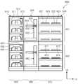
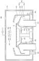
도 2는 기판 처리 설비를 상부에서 바라본 도면이고, 도 3은 도 2의 설비를 A-A 방향에서 바라본 도면이고, 도 4는 도 2의 설비를 B-B 방향에서 바라본 도면이고, 도 5는 도 2의 설비를 C-C 방향에서 바라본 도면이다.FIG. 2 is a view of the substrate processing apparatus viewed from above, FIG. 3 is a view of the apparatus of FIG. 2 viewed from the AA direction, FIG. 4 is a view of the apparatus of FIG. 2 viewed from the BB direction, In the CC direction.
도 2 내지 도 5를 참조하면, 기판 처리 설비(1)는 로드 포트(100), 인덱스 모듈(200), 제 1 버퍼 모듈(300), 도포 및 현상 모듈(400), 제 2 버퍼 모듈(500), 노광 전후 처리 모듈(600), 그리고 인터페이스 모듈(700)을 포함한다. 로드 포트(100), 인덱스 모듈(200), 제 1 버퍼 모듈(300), 도포 및 현상 모듈(400), 제 2 버퍼 모듈(500), 노광 전후 처리 모듈(600), 그리고 인터페이스 모듈(700)은 순차적으로 일 방향으로 일렬로 배치된다.2 to 5, the
이하, 로드 포트(100), 인덱스 모듈(200), 제 1 버퍼 모듈(300), 도포 및 현상 모듈(400), 제 2 버퍼 모듈(500), 노광 전후 처리 모듈(600), 그리고 인터페이스 모듈(700)이 배치된 방향을 제 1 방향(12)이라 칭하고, 상부에서 바라볼 때 제 1 방향(12)과 수직한 방향을 제 2 방향(14)이라 칭하고, 제 1 방향(12) 및 제 2 방향(14)과 각각 수직한 방향을 제 3 방향(16)이라 칭한다.Hereinafter, the
기판(W)은 카세트(20) 내에 수납된 상태로 이동된다. 이때 카세트(20)는 외부로부터 밀폐될 수 있는 구조를 가진다. 예컨대, 카세트(20)로는 전방에 도어를 가지는 전면 개방 일체식 포드(Front Open Unified Pod; FOUP)가 사용될 수 있다.The substrate W is moved in a state accommodated in the
이하에서는 로드 포트(100), 인덱스 모듈(200), 제 1 버퍼 모듈(300), 도포 및 현상 모듈(400), 제 2 버퍼 모듈(500), 노광 전후 처리 모듈(600), 그리고 인터페이스 모듈(700)에 대해 상세히 설명한다.Hereinafter, the
로드 포트(100)는 기판들(W)이 수납된 카세트(20)가 놓여지는 재치대(120)를 가진다. 재치대(120)는 복수개가 제공되며, 재치대들(200)은 제 2 방향(14)을 따라 일렬로 배치된다. 도 2에서는 4개의 재치대(120)가 제공되었다.The
인덱스 모듈(200)은 로드 포트(100)의 재치대(120)에 놓인 카세트(20)와 제 1 버퍼 모듈(300) 간에 기판(W)을 이송한다. 인덱스 모듈(200)은 프레임(210), 인덱스 로봇(220), 그리고 가이드 레일(230)을 가진다. 프레임(210)은 대체로 내부가 빈 직육면체의 형상으로 제공되며, 로드 포트(100)와 제 1 버퍼 모듈(300) 사이에 배치된다. 인덱스 모듈(200)의 프레임(210)은 후술하는 제 1 버퍼 모듈(300)의 프레임(310)보다 낮은 높이로 제공될 수 있다. 인덱스 로봇(220)과 가이드 레일(230)은 프레임(210) 내에 배치된다. 인덱스 로봇(220)은 기판(W)을 직접 핸들링하는 핸드(221)가 제 1 방향(12), 제 2 방향(14), 제 3 방향(16)으로 이동 가능하고 회전될 수 있도록 4축 구동이 가능한 구조를 가진다. 인덱스 로봇(220)은 핸드(221), 아암(222), 지지대(223), 그리고 받침대(224)를 가진다. 핸드(221)는 아암(222)에 고정 설치된다. 아암(222)은 신축 가능한 구조 및 회전 가능한 구조로 제공된다. 지지대(223)는 그 길이 방향이 제 3 방향(16)을 따라 배치된다. 아암(222)은 지지대(223)를 따라 이동 가능하도록 지지대(223)에 결합된다. 지지대(223)는 받침대(224)에 고정결합된다. 가이드 레일(230)은 그 길이 방향이 제 2 방향(14)을 따라 배치되도록 제공된다. 받침대(224)는 가이드 레일(230)을 따라 직선 이동 가능하도록 가이드 레일(230)에 결합된다. 또한, 도시되지는 않았지만, 프레임(210)에는 카세트(20)의 도어를 개폐하는 도어 오프너가 더 제공된다.The
제 1 버퍼 모듈(300)은 프레임(310), 제 1 버퍼(320), 제 2 버퍼(330), 냉각 챔버(350), 그리고 제 1 버퍼 로봇(360)을 가진다. 프레임(310)은 내부가 빈 직육면체의 형상으로 제공되며, 인덱스 모듈(200)과 도포 및 현상 모듈(400) 사이에 배치된다. 제 1 버퍼(320), 제 2 버퍼(330), 냉각 챔버(350), 그리고 제 1 버퍼 로봇(360)은 프레임(310) 내에 위치된다. 냉각 챔버(350), 제 2 버퍼(330), 그리고 제 1 버퍼(320)는 순차적으로 아래에서부터 제 3 방향(16)을 따라 배치된다. 제 1 버퍼(320)는 후술하는 도포 및 현상 모듈(400)의 도포 모듈(401)과 대응되는 높이에 위치되고, 제 2 버퍼(330)와 냉각 챔버(350)는 후술하는 도포 및 현상 모듈(400)의 현상 모듈(402)과 대응되는 높이에 위치된다. 제 1 버퍼 로봇(360)은 제 2 버퍼(330), 냉각 챔버(350), 그리고 제 1 버퍼(320)와 제 2 방향(14)으로 일정 거리 이격되게 위치된다.The
제 1 버퍼(320)와 제 2 버퍼(330)는 각각 복수의 기판들(W)을 일시적으로 보관한다. 제 2 버퍼(330)는 하우징(331)과 복수의 지지대들(332)을 가진다. 지지대들(332)은 하우징(331) 내에 배치되며, 서로 간에 제 3 방향(16)을 따라 이격되게 제공된다. 각각의 지지대(332)에는 하나의 기판(W)이 놓인다. 하우징(331)은 인덱스 로봇(220), 제 1 버퍼 로봇(360), 그리고 후술하는 현상 모듈(402)의 현상부 로봇(482)이 하우징(331) 내 지지대(332)에 기판(W)을 반입 또는 반출할 수 있도록 인덱스 로봇(220)이 제공된 방향, 제 1 버퍼 로봇(360)이 제공된 방향, 그리고 현상부 로봇(482)이 제공된 방향에 개구(도시되지 않음)를 가진다. 제 1 버퍼(320)는 제 2 버퍼(330)와 대체로 유사한 구조를 가진다. 다만, 제 1 버퍼(320)의 하우징(321)에는 제 1 버퍼 로봇(360)이 제공된 방향 및 후술하는 도포 모듈(401)에 위치된 도포부 로봇(432)이 제공된 방향에 개구를 가진다. 제 1 버퍼(320)에 제공된 지지대(322)의 수와 제 2 버퍼(330)에 제공된 지지대(332)의 수는 동일하거나 상이할 수 있다. 일 예에 의하면, 제 2 버퍼(330)에 제공된 지지대(332)의 수는 제 1 버퍼(320)에 제공된 지지대(322)의 수보다 많을 수 있다.The
제 1 버퍼 로봇(360)은 제 1 버퍼(320)와 제 2 버퍼(330) 간에 기판(W)을 이송시킨다. 제 1 버퍼 로봇(360)은 핸드(361), 아암(362), 그리고 지지대(363)를 가진다. 핸드(361)는 아암(362)에 고정 설치된다. 아암(362)은 신축 가능한 구조로 제공되어, 핸드(361)가 제 2 방향(14)을 따라 이동 가능하도록 한다. 아암(362)은 지지대(363)를 따라 제 3 방향(16)으로 직선 이동 가능하도록 지지대(363)에 결합된다. 지지대(363)는 제 2 버퍼(330)에 대응되는 위치부터 제 1 버퍼(320)에 대응되는 위치까지 연장된 길이를 가진다. 지지대(363)는 이보다 위 또는 아래 방향으로 더 길게 제공될 수 있다. 제 1 버퍼 로봇(360)은 단순히 핸드(361)가 제 2 방향(14) 및 제 3 방향(16)을 따른 2축 구동만 되도록 제공될 수 있다.The
냉각 챔버(350)는 각각 기판(W)을 냉각한다. 냉각 챔버(350)는 하우징(351)과 냉각 플레이트(352)를 가진다. 냉각 플레이트(352)는 기판(W)이 놓이는 상면 및 기판(W)을 냉각하는 냉각 수단(353)을 가진다. 냉각 수단(353)으로는 냉각수에 의한 냉각이나 열전 소자를 이용한 냉각 등 다양한 방식이 사용될 수 있다. 또한, 냉각 챔버(350)에는 기판(W)을 냉각 플레이트(352) 상에 위치시키는 리프트 핀 어셈블리(도시되지 않음)가 제공될 수 있다. 하우징(351)은 인덱스 로봇(220) 및 후술하는 현상 모듈(402)에 제공된 현상부 로봇(482)이 냉각 플레이트(352)에 기판(W)을 반입 또는 반출할 수 있도록 인덱스 로봇(220)이 제공된 방향 및 현상부 로봇(482)이 제공된 방향에 개구(도시되지 않음)를 가진다. 또한, 냉각 챔버(350)에는 상술한 개구를 개폐하는 도어들(도시되지 않음)이 제공될 수 있다.The cooling
도포 및 현상 모듈(400)은 노광 공정 전에 기판(W) 상에 포토 레지스트를 도포하는 공정 및 노광 공정 후에 기판(W)을 현상하는 공정을 수행한다. 도포 및 현상 모듈(400)은 대체로 직육면체의 형상을 가진다. 도포 및 현상 모듈(400)은 도포 모듈(401)과 현상 모듈(402)을 가진다. 도포 모듈(401)과 현상 모듈(402)은 서로 간에 층으로 구획되도록 배치된다. 일 예에 의하면, 도포 모듈(401)은 현상 모듈(402)의 상부에 위치된다.The application and
도포 모듈(401)은 기판(W)에 대해 포토레지스트와 같은 감광액을 도포하는 공정 및 레지스트 도포 공정 전후에 기판(W)에 대해 가열 및 냉각과 같은 열처리 공정을 포함한다. 도포 모듈(401)은 도포 유닛(410), 베이크 챔버(420), 반송 챔버(430), 그리고 에어 공급 유닛(820), 그리고 배기 어셈블리(1000)를 가진다. 도포 유닛(410), 베이크 챔버(420), 그리고 반송 챔버(430)는 제 2 방향(14)을 따라 순차적으로 배치된다. 따라서 도포 유닛(410)과 베이크 챔버(420)는 반송 챔버(430)를 사이에 두고 제 2 방향(14)으로 서로 이격되게 위치된다. 도포 유닛(410)은 복수 개가 제공되며, 제 1 방향(12) 및 제 3 방향(16)으로 각각 복수 개씩 제공된다. 도면에서는 6개의 도포 유닛(410)이 제공된 예가 도시되었다. 베이크 챔버(420)는 제 1 방향(12) 및 제 3 방향(16)으로 각각 복수 개씩 제공된다. 도면에서는 6개의 베이크 챔버(420)가 제공된 예가 도시되었다. 그러나 이와 달리 베이크 챔버(420)는 더 많은 수로 제공될 수 있다.The
반송 챔버(430)는 제 1 버퍼 모듈(300)의 제 1 버퍼(320)와 제 1 방향(12)으로 나란하게 위치된다. 반송 챔버(430) 내에는 도포부 로봇(432)과 가이드 레일(433)이 위치된다. 반송 챔버(430)는 대체로 직사각의 형상을 가진다. 도포부 로봇(432)은 베이크 챔버들(420), 도포 유닛들(410), 제 1 버퍼 모듈(300)의 제 1 버퍼(320), 그리고 후술하는 제 2 버퍼 모듈(500)의 제 1 냉각 챔버(520) 간에 기판(W)을 이송한다. 가이드 레일(433)은 그 길이 방향이 제 1 방향(12)과 나란하도록 배치된다. 가이드 레일(433)은 도포부 로봇(432)이 제 1 방향(12)으로 직선 이동되도록 안내한다. 도포부 로봇(432)은 핸드(434), 아암(435), 지지대(436), 그리고 받침대(437)를 가진다. 핸드(434)는 아암(435)에 고정 설치된다. 아암(435)은 신축 가능한 구조로 제공되어 핸드(434)가 수평 방향으로 이동 가능하도록 한다. 지지대(436)는 그 길이 방향이 제 3 방향(16)을 따라 배치되도록 제공된다. 아암(435)은 지지대(436)를 따라 제 3 방향(16)으로 직선 이동 가능하도록 지지대(436)에 결합된다. 지지대(436)는 받침대(437)에 고정 결합되고, 받침대(437)는 가이드 레일(433)을 따라 이동 가능하도록 가이드 레일(433)에 결합된다.The
도포 유닛들(410)은 모두 동일한 구조를 가진다. 다만, 각각의 도포 유닛(410)에서 사용되는 포토 레지스트의 종류는 서로 상이할 수 있다. 일 예로서 포토 레지스트로는 화학 증폭형 레지스트(chemical amplification resist)가 사용될 수 있다. 도 6은 도 2의 도포 유닛을 보여주는 단면도이다. 도 6을 참조하면, 도포 유닛(410)는 하우징(810), 기판 지지 유닛(830), 처리 용기(850), 승강 유닛(890), 그리고 액 공급 유닛(840)을 포함한다.The
하우징(810)은 내부에 공간(812)을 가지는 직사각의 통 형상으로 제공된다. 하우징(810)의 일측에는 개구(미도시)가 형성된다. 개구는 기판(W)이 반출입되는 입구로 기능한다. 개구에는 도어가 설치되며, 도어는 개구를 개폐한다. 도어는 기판 처리 공정이 진행되면, 개구를 차단하여 하우징(810)의 내부 공간(812)을 밀폐한다. 하우징(810)의 바닥면에는 배기구(814)가 형성되고, 천장면에는 공급구가 형성된다. 하우징(810) 내에는 공급구를 통해 하강 기류가 형성되고, 형성된 기류는 배기구(814)를 통해 외부로 배기된다. 공급구에는 에어 공급 유닛이 연결되며, 에어 공급 유닛은 공급구에 청정 에어를 공급한다. 배기구(814)에는 배기 어셈블리(1000)가 연결되며, 배기 어셈블리(1000)는 배기구(814)를 감압할 수 있다.The
기판 지지 유닛(830)은 하우징(810)의 내부 공간에서 기판(W)을 지지한다. 기판 지지 유닛(830)은 기판(W)을 회전시킨다. 기판 지지 유닛(830)은 스핀척(832), 회전축(834), 그리고 구동기(836)를 포함한다. 스핀척(832)은 기판을 지지하는 기판 지지 부재(832)로 제공된다. 스핀척(832)은 원형의 판 형상을 가지도록 제공된다. 스핀척(832)의 상면에는 기판(W)이 접촉한다. 스핀척(832)은 기판(W)보다 작은 직경을 가지도록 제공된다. 일 예에 의하면, 스핀척(832)은 기판(W)을 진공 흡입하여 기판(W)을 척킹할 수 있다. 선택적으로, 스핀척(832)은 정전기를 이용하여 기판(W)을 척킹하는 정전척으로 제공될 수 있다. 또한 스핀척(832)은 기판(W)을 물리적 힘으로 척킹할 수 있다.The
회전축(834) 및 구동기(836)는 스핀척(832)을 회전시키는 회전 구동 부재(834,836)로 제공된다. 회전축(834)은 스핀척(832)의 아래에서 스핀척(832)을 지지한다. 회전축(834)은 그 길이방향이 상하방향을 향하도록 제공된다. 회전축(834)은 그 중심축을 중심으로 회전 가능하도록 제공된다. 구동기(836)는 회전축(834)이 회전되도록 구동력을 제공한다. 예컨대, 구동기(836)는 회전축의 회전 속도를 가변 가능한 모터일 수 있다.The
처리 용기(850)는 하우징(810)의 내부 공간(812)에 위치된다. 처리 용기(850)는 상부가 개방된 컵 형상을 가지도록 제공된다. 처리 용기(850)는 내부에 처리 공간을 제공한다. 처리 용기(850)는 기판 지지 유닛(830)의 둘레를 감싸도록 제공된다. 즉, 기판 지지 유닛(830)은 처리 공간에 위치된다. 처리 용기(850)는 외측컵(862) 및 내측컵(852)을 포함한다. 외측컵(862)은 기판 지지 유닛(830)의 둘레를 감싸도록 제공되고, 내측컵(852)은 외측컵(862)의 내측에 위치된다. 외측컵(862) 및 내측컵(852) 각각은 환형의 링 형상으로 제공된다. 외측컵(862)과 내측컵(852)의 사이 공간은 액이 회수되는 회수 경로(851)로 기능한다.The
내측컵(852)은 회전축(834)을 감싸는 원형의 판 형상으로 제공된다. 상부에서 바라볼 때 내측컵(852)은 배기구(814)와 중첩되도록 위치된다. 내측컵은 내측부 및 외측부를 가진다. 내측부와 외측부 각각의 상면은 서로 상이한 각도로 경사지도록 제공된다. 상부에서 바라볼 때 내측부는 스핀척과 중첩되게 위치된다. 내측부는 회전축(836)과 마주하게 위치된다. 내측부는 회전축(836)으로부터 멀어질수록 상향 경사진 방향을 향하고, 외측부는 내측부로부터 외측 방향으로 연장된다. 외측부는 회전축(836)으로부터 멀어질수록 하향 경사진 방향을 향한다. 내측부의 상단은 기판(W)의 측단부와 상하 방향으로 일치될 수 있다. 일 예에 의하면, 외측부와 내측부가 만나는 지점은 내측부의 상단보다 낮은 위치일 수 있다. 내측부와 외측부가 서로 만나는 지점은 라운드지도록 제공될 수 있다. 외측부는 외측컵(862)과 조합되어 처리액이 회수되는 회수 경로(851)를 형성할 수 있다.The
외측컵(862)은 기판 지지 유닛(830) 및 내측컵(852)을 감싸는 컵 형상을 가지도록 제공된다. 외측컵(862)은 바닥부(864), 측부(866), 그리고 경사부(870)을 가진다. 바닥부(864)는 중공을 가지는 원형의 판 형상을 가지도록 제공된다. 바닥부(864)에는 회수 라인(865)이 연결된다. 회수 라인(865)은 기판(W) 상에 공급된 처리액을 회수한다. 회수 라인(865)에 의해 회수된 처리액은 외부의 액 재생 시스템에 의해 재사용될 수 있다. 측부(866)는 기판 지지 유닛(830)을 감싸는 환형의 링 형상을 가지도록 제공된다. 측부(866)는 바닥부(864)의 측단으로부터 수직한 방향으로 연장된다. 측부(866)는 바닥부(864)으로부터 위로 연장된다.The
경사부(870)는 측부(866)의 상단으로부터 외측컵(862)의 중심축을 향하는 방향으로 연장된다. 경사부(870)의 내측면(870a)은 기판 지지 유닛(830)에 가까워지도록 상향 경사지게 제공된다. 경사부(870)은 링 형상을 가지도록 제공된다. 기판의 액 처리 공정 중에는 경사부(870)의 상단이 기판 지지 유닛(830)에 지지된 기판(W)보다 높게 위치된다.The
승강 유닛(890)은 내측 컵(852) 및 외측 컵(862)을 각각 승강 이동시킨다. 승강 유닛(890)은 내측 이동 부재(892) 및 외측 이동 부재(894)를 포함한다. 내측 이동 부재(892)는 내측 컵(852)을 승강 이동 시키고, 외측 이동 부재(894)는 외측 컵(862)을 승강 이동시킨다.The elevating unit 890 lifts the
액 공급 유닛(840)은 기판(W) 상에 처리액 및 프리 웨트액을 공급한다. 액 공급 유닛(840)은 이동 부재(846), 아암(848), 프리 웨트 노즐(842) 및 처리 노즐(844)을 포함한다. 이동 부재(846)는 아암(848)을 수평 방향으로 이동시키는 이동 레일(846)을 포함한다. 이동 레일(846)은 처리 용기(850)의 일측에 위치된다. 이동 레일(846)은 그 길이 방향이 수평 방향을 향하도록 제공된다. 일 예에 의하면, 이동 레일(846)의 길이 방향을 제1방향과 평행한 방향을 향하도록 제공될 수 있다. 이동 레일(846)에는 아암(848)이 설치된다. 아암(848)은 이동 레일(846)의 내부에 제공된 리니어 모터에 의해 이동될 수 있다. 아암(848)은 상부에서 바라볼 때 이동 레일(846)과 수직한 길이 방향을 향하도록 제공된다. 아암(848)의 일단은 이동 레일(846)에 장착된다. 아암(848)의 타단 저면에는 프리 웨트 노즐(842) 및 처리 노즐(844)이 각각 설치된다. 상부에서 바라볼 때 프리 웨트 노즐(842) 및 처리 노즐(844)은 이동 레일(846)의 길이 방향과 평행한 방향으로 배열된다. 선택적으로 아암(848)은 복수 개로 제공되며, 아암들(848) 각각에는 프리 웨트 노즐(842) 및 처리 노즐(844)이 설치될 수 있다. 또한 아암(848)은 길이 방향이 제3방향을 향하는 회전축에 결합되어 회전될 수 있다.The
프리 웨트 노즐(842)은 기판(W) 상에 프리 웨트액을 공급하고, 처리 노즐(844)은 기판(W) 상에 처리액을 공급한다. 예컨대, 프리 웨트액은 기판(W)의 표면 성질을 변화시킬 수 있는 액일 수 있다. 프리 웨트액은 기판(W)의 표면을 소수성 성질로 변화시킬 수 있다. 프리 웨트액은 신나(Thinner)이고, 처리액은 포토 레지스트와 같은 감광액일 수 있다. The
다음은 에어 공급 유닛(820) 및 배기 어셈블리(1000)에 대해 설명한다. 에어 공급 유닛(820)은 복수 개의 도포 유닛들에 청정 에어를 공급하고, 배기 어셈블리(1000)는 복수 개의 도포 유닛들을 배기한다. 본 실시예에는 설명의 편의상 에어 공급 유닛(820) 및 배기 어셈블리(1000)가 2 개의 도포 유닛(410)인 제1공정 유닛(410a) 및 제2공정 유닛(410b)에 연결되는 것으로 설명한다. 그러나 본 실시예는 이에 한정되지 않으며, 3 개 이상의 도포 유닛에 연결된다.Next, the
에어 공급 유닛(820)은 제1공정 유닛(410a) 및 제2공정 유닛(410b) 각각의 내부 공간(812)에 하강 기류를 형성한다. 에어 공급 유닛(820)은 메인 공급 라인(822), 제1공급 라인(824), 제2공급 라인(826), 필터(828), 그리고 공급 팬(821)을 포함한다. 제1공급 라인(824)은 메인 공급 라인(822)으로부터 제1공급 지점(822a)에서 분기되어 제1공정 유닛(410a)에 연결된다. 제1공급 라인(824)은 제1공정 유닛(410a)의 천장면에 연결된다. 제2공급 라인(826)은 메인 공급 라인(822)으로부터 제2공급 지점(822b)에서 분기되어 제2공정 유닛(410b)에 연결된다. 제2공급 라인(826)은 제2공정 유닛(410b)의 천장면에 연결된다. 공급 팬(821)은 메인 공급 라인(822)에 설치되며, 메인 공급 라인(822)에 에어를 블로우한다. 공급 팬(821)은 메인 공급 라인(822) 상에서 제2공급 지점(822b)보다 제1공급 지점(822a)에 더 가깝게 위치된다. 따라서 공급 팬(821)으로부터 블로우되는 에어는 제1공급 지점(822a)에 우선 공급되고, 이후에 제2공급 지점(822b)으로 공급된다. 필터(828)는 제1공정 유닛(410a) 및 제2공정 유닛(410b) 각각의 천장면에 설치되어 에어에 포함된 이물질을 필터(828)링한다.The
배기 어셈블리(1000)는 제1공정 유닛(410a) 및 제2공정 유닛(410b) 각각의 내부 공간을 배기한다. 배기 어셈블리(1000)는 메인 배기 라인(1020), 감압 부재(1040), 제1배기 라인(1060), 제2배기 라인(1080), 보충 부재(1200), 측정 부재(1090), 그리고 제어기(1400)를 포함한다. 제1배기 라인(1060)은 메인 배기 라인(1020)으로부터 제1배기 지점(1020a)에서 분기되어 제1공정 유닛(410a)에 연결된다. 제1배기 라인(1060)은 제1공정 유닛(410a)의 배기구에 연결된다. 제2배기 라인(1080)은 메인 배기 라인(1020)으로부터 제2배기 지점(1020b)에서 분기되어 제2공정 유닛(410b)에 연결된다. 제2배기 라인(1080)은 제2공정 유닛(410b)의 배기구에 연결된다. 감압 부재(1040)는 메인 배기 라인(1020)에서 제2배기 지점(1020b)보다 제1배기 지점(1020a)에 더 가깝게 위치된다. 따라서 감압 부재(1040)와 각 배기 지점의 거리차로 인해 제1공정 유닛(410a)과 제2공정 유닛(410b) 간에는 배기 편차가 발생된다.The
보충 부재(1200)는 각 공정 유닛(410) 간에 배기 편차를 최소화시킨다. 보충 부재(1200)는 배기력이 부족한 공정 유닛(410)에 배기력을 강화시킨다. 보충 부재(1200)는 메인 배기 라인(1020)에 설치되어 메인 배기 라인(1020)에 에어를 공급한다.The replenishing
보충 부재(1200)는 보충 라인(1220) 및 보충 팬(1240)을 포함한다. 보충 라인(1220)은 메인 배기 라인(1020)의 제3배기 지점(1020c)에 연결된다. 제3배기 지점(1020c)은 메인 배기 라인(1020)에서 감압 부재(1040)에 대해 제2배기 지점(1020b)보다 멀게 위치되는 지점이다. 일 예에 의하면, 메인 배기 라인(1020) 상에는 감압 부재(1040), 제1배기 지점(1020a), 제2배기 지점(1020b), 그리고 제3배기 지점(1020c)이 순차적으로 배열되게 위치될 수 있다. 보충 팬(1240)은 보충 라인(1220)에 설치된다. 보충 팬(1240)은 보충 라인(1220)에 에어를 공급한다. 보충 팬(1240)은 제3배기 지점(1020c)에서 제2배기 지점(1020b)을 향하는 방향으로 에어를 공급한다.The
측정 부재(1090)는 제1공정 유닛(410a) 및 제2공정 유닛(410b) 각각의 압력을 측정한다. 측정된 압력은 제어기(1400)에 전달되고, 제어기(1400)는 전달받은 압력 정보를 근거로 보충 팬(1240)을 제어한다. 측정 부재(1090)는 제1공정 유닛(410a)에 위치되는 제1압력 센서(1090a) 및 제2공정 유닛(410b)에 위치되는 제2압력 센서(1090b)를 포함한다. 일 예에 의하면, 제어기(1400)는 제1공정 유닛(410a)의 제1배기 압력 정보 및 제2공정 유닛(410b)의 제2배기 압력 정보를 제공받고, 제2배기 압력이 제1배기 압력에 도달되도록 보충 팬(1240)을 제어할 수 있다. 제어기(1400)는 제1공정 유닛(410a)과 제2공정 유닛(410b) 간에 배기 편차가 최소화되도록 에어의 유량을 조절 가능하다.The measuring
다음은 배기 어셈블리(1000)의 제2실시예에 대해 설명한다. 도 8을 참조하면, 보충 라인(1220)은 에어 공급 유닛(820)과 메인 배기 라인(1020)에 각각 연결될 수 있다. 보충 라인(1220)은 메인 공급 라인(822)의 제3공급 지점(822c) 및 메인 배기 라인(1020)의 제3배기 지점(1020c)에 연결될 수 있다. 여기서 제3공급 지점(822c)은 메인 공급 라인(822)에서 공급 팬에 대해 제2공급 지점(822b)보다 멀리 떨어진 위치이다. 즉 메인 공급 라인(822)에서 공급 팬(821), 제1공급 지점(822a), 제2공급 지점(822b), 그리고 제3공급 지점(822c)은 순차적으로 배열되게 위치될 수 있다. 본 발명의 제1실시예의 경우, 에어의 공급 방향에 대한 관성에 의해 에어는 제1공정 유닛(410a)보다 제2공정 유닛(410b)에 더 다량으로 공급된다. 제2실시예에는 제3공급 지점(822c)에 보충 라인(1220)을 연결함에 따라 제1공정 유닛(410a) 및 제2공정 유닛(410b)에 균일한 유량의 에어를 공급 가능하다. 또한 메인 공급 라인(822)에서 발생된 잉여 에어는 보충 라인(1220)으로 공급된다. 보충 라인(1220)에는 유량 조절 밸브(1240a)가 설치된다. 유량 조절 밸브(1240a)는 보충 라인(1220)에서 필요로 하는 유량의 에어를 메인 공급 라인(822)으로부터 제공받아, 이를 메인 배기 라인(1020)으로 보충하도록 보충 라인(1220)을 개폐한다. 제어기(1400)는 제1배기 압력 정보 및 제2배기 압력 정보를 근거로 유량 조절 밸브(1240a)를 제어하여 제1공정 유닛(410a) 및 제2공정 유닛(410b)의 배기 압력을 균일하게 조절할 수 있다. 보충 라인(1220)으로부터 메인 배기 라인(1020)으로 공급되는 에어는 제1공정 유닛(410a)과 제2공정 유닛(410b)의 배기 편차를 최소화할 수 있다.Next, a second embodiment of the
다음은 배기 어셈블리(1000)의 제3실시예에 대해 설명한다. 도 9를 참조하면, 보충 부재(1200)는 보충 배기 라인(1260) 및 배기 밸브(1240c)를 더 포함할 수 있다. 보충 라인(1220)은 상술한 제2실시예와 같이 메인 공급 라인(822)과 메인 배기 라인(1020)을 연결할 수 있다. 보충 배기 라인(1260)은 보충 라인(1220)으로부터 분기되는 라인으로 제공될 수 있다. 보충 배기 라인(1260)에는 배기 밸브(1240c)가 설치될 수 있다. 배기 밸브(1240c)는 보충 라인(1220)에 공급되는 잉여 에어 중 일부를 배기하여 메인 배기 라인(1020)에 보충되는 에어의 유량을 제어할 수 있다. 제어기(1400)는 제1배기 압력 정보 및 제2배기 압력 정보를 근거로 배기 밸브(1240c)를 제어하여 제1공정 유닛(410a) 및 제2공정 유닛(410b)의 배기 압력을 균일하게 조절할 수 있다.Next, a third embodiment of the
다시 도 2 내지 도 5를 참조하면, 베이크 챔버(420)는 기판(W)을 열처리한다. 예컨대, 베이크 챔버들(420)은 포토 레지스트를 도포하기 전에 기판(W)을 소정의 온도로 가열하여 기판(W) 표면의 유기물이나 수분을 제거하는 프리 베이크(prebake) 공정이나 포토레지스트를 기판(W) 상에 도포한 후에 행하는 소프트 베이크(soft bake) 공정 등을 수행하고, 각각의 가열 공정 이후에 기판(W)을 냉각하는 냉각 공정 등을 수행한다. 베이크 챔버(420)는 냉각 플레이트(421) 또는 가열 플레이트(422)를 가진다. 냉각 플레이트(421)에는 냉각수 또는 열전 소자와 같은 냉각 수단(423)이 제공된다. 또한 가열 플레이트(422)에는 열선 또는 열전 소자와 같은 가열 수단(424)이 제공된다. 냉각 플레이트(421)와 가열 플레이트(422)는 하나의 베이크 챔버(420) 내에 각각 제공될 수 있다. 선택적으로 베이크 챔버(420)들 중 일부는 냉각 플레이트(421)만을 구비하고, 다른 일부는 가열 플레이트(422)만을 구비할 수 있다.2 to 5, the
현상 모듈(402)은 기판(W) 상에 패턴을 얻기 위해 현상액을 공급하여 포토 레지스트의 일부를 제거하는 현상 공정, 및 현상 공정 전후에 기판(W)에 대해 수행되는 가열 및 냉각과 같은 열처리 공정을 포함한다. 현상모듈(402)은 현상 챔버(460), 베이크 챔버(470), 그리고 반송 챔버(480)를 가진다. 현상 챔버(460), 베이크 챔버(470), 그리고 반송 챔버(480)는 제 2 방향(14)을 따라 순차적으로 배치된다. 따라서 현상 챔버(460)와 베이크 챔버(470)는 반송 챔버(480)를 사이에 두고 제 2 방향(14)으로 서로 이격되게 위치된다. 현상 챔버(460)는 복수 개가 제공되며, 제 1 방향(12) 및 제 3 방향(16)으로 각각 복수 개씩 제공된다. 도면에서는 6개의 현상 챔버(460)가 제공된 예가 도시되었다. 베이크 챔버(470)는 제 1 방향(12) 및 제 3 방향(16)으로 각각 복수 개씩 제공된다. 도면에서는 6개의 베이크 챔버(470)가 제공된 예가 도시되었다. 그러나 이와 달리 베이크 챔버(470)는 더 많은 수로 제공될 수 있다.The developing
반송 챔버(480)는 제 1 버퍼 모듈(300)의 제 2 버퍼(330)와 제 1 방향(12)으로 나란하게 위치된다. 반송 챔버(480) 내에는 현상부 로봇(482)과 가이드 레일(483)이 위치된다. 반송 챔버(480)는 대체로 직사각의 형상을 가진다. 현상부 로봇(482)은 베이크 챔버들(470), 현상 챔버들(460), 제 1 버퍼 모듈(300)의 제 2 버퍼(330)와 냉각 챔버(350), 그리고 제 2 버퍼 모듈(500)의 제 2 냉각 챔버(540) 간에 기판(W)을 이송한다. 가이드 레일(483)은 그 길이 방향이 제 1 방향(12)과 나란하도록 배치된다. 가이드 레일(483)은 현상부 로봇(482)이 제 1 방향(12)으로 직선 이동되도록 안내한다. 현상부 로봇(482)은 핸드(484), 아암(485), 지지대(486), 그리고 받침대(487)를 가진다. 핸드(484)는 아암(485)에 고정 설치된다. 아암(485)은 신축 가능한 구조로 제공되어 핸드(484)가 수평 방향으로 이동 가능하도록 한다. 지지대(486)는 그 길이 방향이 제 3 방향(16)을 따라 배치되도록 제공된다. 아암(485)은 지지대(486)를 따라 제 3 방향(16)으로 직선 이동 가능하도록 지지대(486)에 결합된다. 지지대(486)는 받침대(487)에 고정 결합된다. 받침대(487)는 가이드 레일(483)을 따라 이동 가능하도록 가이드 레일(483)에 결합된다.The
현상 챔버들(460)은 모두 동일한 구조를 가진다. 다만, 각각의 현상 챔버(460)에서 사용되는 현상액의 종류는 서로 상이할 수 있다. 현상 챔버(460)는 기판(W) 상의 포토 레지스트 중 광이 조사된 영역을 제거한다. 이때, 보호막 중 광이 조사된 영역도 같이 제거된다. 선택적으로 사용되는 포토 레지스트의 종류에 따라 포토 레지스트 및 보호막의 영역들 중 광이 조사되지 않은 영역만이 제거될 수 있다.The
현상 챔버(460)는 용기(461), 지지 플레이트(462), 그리고 노즐(463)을 가진다. 용기(461)는 상부가 개방된 컵 형상을 가진다. 지지 플레이트(462)는 용기(461) 내에 위치되며, 기판(W)을 지지한다. 지지 플레이트(462)는 회전 가능하게 제공된다. 노즐(463)은 지지 플레이트(462)에 놓인 기판(W) 상으로 현상액을 공급한다. 노즐(463)은 원형의 관 형상을 가지고, 기판(W)의 중심으로 현상액 공급할 수 있다. 선택적으로 노즐(463)은 기판(W)의 직경에 상응하는 길이를 가지고, 노즐(463)의 토출구는 슬릿으로 제공될 수 있다. 또한, 현상 챔버(460)에는 추가적으로 현상액이 공급된 기판(W) 표면을 세정하기 위해 탈이온수와 같은 세정액을 공급하는 노즐(464)이 더 제공될 수 있다.The
베이크 챔버(470)는 기판(W)을 열처리한다. 예컨대, 베이크 챔버들(470)은 현상 공정이 수행되기 전에 기판(W)을 가열하는 포스트 베이크 공정 및 현상 공정이 수행된 후에 기판(W)을 가열하는 하드 베이크 공정 및 각각의 베이크 공정 이후에 가열된 기판(W)을 냉각하는 냉각 공정 등을 수행한다. 베이크 챔버(470)는 냉각 플레이트(471) 또는 가열 플레이트(472)를 가진다. 냉각 플레이트(471)에는 냉각수 또는 열전 소자와 같은 냉각 수단(473)이 제공된다. 또는 가열 플레이트(472)에는 열선 또는 열전 소자와 같은 가열 수단(474)이 제공된다. 냉각 플레이트(471)와 가열 플레이트(472)는 하나의 베이크 챔버(470) 내에 각각 제공될 수 있다. 선택적으로 베이크 챔버(470)들 중 일부는 냉각 플레이트(471)만을 구비하고, 다른 일부는 가열 플레이트(472)만을 구비할 수 있다.The
상술한 바와 같이 도포 및 현상 모듈(400)에서 도포 모듈(401)과 현상 모듈(402)은 서로 간에 분리되도록 제공된다. 또한, 상부에서 바라볼 때 도포 모듈(401)과 현상 모듈(402)은 동일한 챔버 배치를 가질 수 있다.As described above, in the application and
제 2 버퍼 모듈(500)은 도포 및 현상 모듈(400)과 노광 전후 처리 모듈(600) 사이에 기판(W)이 운반되는 통로로서 제공된다. 또한, 제 2 버퍼 모듈(500)은 기판(W)에 대해 냉각 공정이나 에지 노광 공정 등과 같은 소정의 공정을 수행한다. 제 2 버퍼 모듈(500)은 프레임(510), 버퍼(520), 제 1 냉각 챔버(530), 제 2 냉각 챔버(540), 에지 노광 챔버(550), 그리고 제 2 버퍼 로봇(560)을 가진다. 프레임(510)은 직육면체의 형상을 가진다. 버퍼(520), 제 1 냉각 챔버(530), 제 2 냉각 챔버(540), 에지 노광 챔버(550), 그리고 제 2 버퍼 로봇(560)은 프레임(510) 내에 위치된다. 버퍼(520), 제 1 냉각 챔버(530), 그리고 에지 노광 챔버(550)는 도포 모듈(401)에 대응하는 높이에 배치된다. 제 2 냉각 챔버(540)는 현상 모듈(402)에 대응하는 높이에 배치된다. 버퍼(520), 제 1 냉각 챔버(530), 그리고 제 2 냉각 챔버(540)는 순차적으로 제 3 방향(16)을 따라 일렬로 배치된다. 상부에서 바라볼 때 버퍼(520)은 도포 모듈(401)의 반송 챔버(430)와 제 1 방향(12)을 따라 배치된다. 에지 노광 챔버(550)는 버퍼(520) 또는 제 1 냉각 챔버(530)와 제 2 방향(14)으로 일정 거리 이격되게 배치된다.The
제 2 버퍼 로봇(560)은 버퍼(520), 제 1 냉각 챔버(530), 그리고 에지 노광 챔버(550) 간에 기판(W)을 운반한다. 제 2 버퍼 로봇(560)은 에지 노광 챔버(550)와 버퍼(520) 사이에 위치된다. 제 2 버퍼 로봇(560)은 제 1 버퍼 로봇(360)과 유사한 구조로 제공될 수 있다. 제 1 냉각 챔버(530)와 에지 노광 챔버(550)는 도포 모듈(401)에서 공정이 수행된 기판들(W)에 대해 후속 공정을 수행한다. 제 1 냉각 챔버(530)는 도포 모듈(401)에서 공정이 수행된 기판(W)을 냉각한다. 제 1 냉각 챔버(530)는 제 1 버퍼 모듈(300)의 냉각 챔버(350)과 유사한 구조를 가진다. 에지 노광 챔버(550)는 제 1 냉각 챔버(530)에서 냉각 공정이 수행된 기판들(W)에 대해 그 가장자리를 노광한다. 버퍼(520)는 에지 노광 챔버(550)에서 공정이 수행된 기판들(W)이 후술하는 전처리 모듈(601)로 운반되기 전에 기판(W)을 일시적으로 보관한다. 제 2 냉각 챔버(540)는 후술하는 후처리 모듈(602)에서 공정이 수행된 기판들(W)이 현상 모듈(402)로 운반되기 전에 기판들(W)을 냉각한다. 제 2 버퍼 모듈(500)은 현상 모듈(402)와 대응되는 높이에 추가된 버퍼를 더 가질 수 있다. 이 경우, 후처리 모듈(602)에서 공정이 수행된 기판들(W)은 추가된 버퍼에 일시적으로 보관된 후 현상 모듈(402)로 운반될 수 있다.The
노광 전후 처리 모듈(600)은, 노광 장치(900)가 액침 노광 공정을 수행하는 경우, 액침 노광시에 기판(W)에 도포된 포토레지스트 막을 보호하는 보호막을 도포하는 공정을 처리할 수 있다. 또한, 노광 전후 처리 모듈(600)은 노광 이후에 기판(W)을 세정하는 공정을 수행할 수 있다. 또한, 화학증폭형 레지스트를 사용하여 도포 공정이 수행된 경우, 노광 전후 처리 모듈(600)은 노광 후 베이크 공정을 처리할 수 있다.The pre- and
노광 전후 처리 모듈(600)은 전처리 모듈(601)과 후처리 모듈(602)을 가진다. 전처리 모듈(601)은 노광 공정 수행 전에 기판(W)을 처리하는 공정을 수행하고, 후처리 모듈(602)은 노광 공정 이후에 기판(W)을 처리하는 공정을 수행한다. 전처리 모듈(601)과 후처리 모듈(602)은 서로 간에 층으로 구획되도록 배치된다. 일 예에 의하면, 전처리 모듈(601)은 후처리 모듈(602)의 상부에 위치된다. 전처리 모듈(601)은 도포 모듈(401)과 동일한 높이로 제공된다. 후처리 모듈(602)은 현상 모듈(402)과 동일한 높이로 제공된다. 전처리 모듈(601)은 보호막 도포 챔버(610), 베이크 챔버(620), 그리고 반송 챔버(630)를 가진다. 보호막 도포 챔버(610), 반송 챔버(630), 그리고 베이크 챔버(620)는 제 2 방향(14)을 따라 순차적으로 배치된다. 따라서 보호막 도포 챔버(610)와 베이크 챔버(620)는 반송 챔버(630)를 사이에 두고 제 2 방향(14)으로 서로 이격되게 위치된다. 보호막 도포 챔버(610)는 복수 개가 제공되며, 서로 층을 이루도록 제 3 방향(16)을 따라 배치된다. 선택적으로 보호막 도포 챔버(610)는 제 1 방향(12) 및 제 3 방향(16)으로 각각 복수 개씩 제공될 수 있다. 베이크 챔버(620)는 복수 개가 제공되며, 서로 층을 이루도록 제 3 방향(16)을 따라 배치된다. 선택적으로 베이크 챔버(620)는 제 1 방향(12) 및 제 3 방향(16)으로 각각 복수 개씩 제공될 수 있다.The
반송 챔버(630)는 제 2 버퍼 모듈(500)의 제 1 냉각 챔버(530)와 제 1 방향(12)으로 나란하게 위치된다. 반송 챔버(630) 내에는 전처리 로봇(632)이 위치된다. 반송 챔버(630)는 대체로 정사각 또는 직사각의 형상을 가진다. 전처리 로봇(632)은 보호막 도포 챔버들(610), 베이크 챔버들(620), 제 2 버퍼 모듈(500)의 버퍼(520), 그리고 후술하는 인터페이스 모듈(700)의 제 1 버퍼(720) 간에 기판(W)을 이송한다. 전처리 로봇(632)은 핸드(633), 아암(634), 그리고 지지대(635)를 가진다. 핸드(633)는 아암(634)에 고정 설치된다. 아암(634)은 신축 가능한 구조 및 회전 가능한 구조로 제공된다. 아암(634)은 지지대(635)를 따라 제 3 방향(16)으로 직선 이동 가능하도록 지지대(635)에 결합된다.The
보호막 도포 챔버(610)는 액침 노광 시에 레지스트 막을 보호하는 보호막을 기판(W) 상에 도포한다. 보호막 도포 챔버(610)는 하우징(611), 지지 플레이트(612), 그리고 노즐(613)을 가진다. 하우징(611)은 상부가 개방된 컵 형상을 가진다. 지지 플레이트(612)는 하우징(611) 내에 위치되며, 기판(W)을 지지한다. 지지 플레이트(612)는 회전 가능하게 제공된다. 노즐(613)은 지지 플레이트(612)에 놓인 기판(W) 상으로 보호막 형성을 위한 보호액을 공급한다. 노즐(613)은 원형의 관 형상을 가지고, 기판(W)의 중심으로 보호액을 공급할 수 있다. 선택적으로 노즐(613)은 기판(W)의 직경에 상응하는 길이를 가지고, 노즐(613)의 토출구는 슬릿으로 제공될 수 있다. 이 경우, 지지 플레이트(612)는 고정된 상태로 제공될 수 있다. 보호액은 발포성 재료를 포함한다. 보호액은 포토 레지스터 및 물과의 친화력이 낮은 재료가 사용될 수 있다. 예컨대, 보호액은 불소계의 용제를 포함할 수 있다. 보호막 도포 챔버(610)는 지지 플레이트(612)에 놓인 기판(W)을 회전시키면서 기판(W)의 중앙 영역으로 보호액을 공급한다.The protective
베이크 챔버(620)는 보호막이 도포된 기판(W)을 열처리한다. 베이크 챔버(620)는 냉각 플레이트(621) 또는 가열 플레이트(622)를 가진다. 냉각 플레이트(621)에는 냉각수 또는 열전 소자와 같은 냉각 수단(623)이 제공된다. 또는 가열 플레이트(622)에는 열선 또는 열전 소자와 같은 가열 수단(624)이 제공된다. 가열 플레이트(622)와 냉각 플레이트(621)는 하나의 베이크 챔버(620) 내에 각각 제공될 수 있다. 선택적으로 베이크 챔버들(620) 중 일부는 가열 플레이트(622) 만을 구비하고, 다른 일부는 냉각 플레이트(621) 만을 구비할 수 있다.The
후처리 모듈(602)은 세정 챔버(660), 노광 후 베이크 챔버(670), 그리고 반송 챔버(680)를 가진다. 세정 챔버(660), 반송 챔버(680), 그리고 노광 후 베이크 챔버(670)는 제 2 방향(14)을 따라 순차적으로 배치된다. 따라서 세정 챔버(660)와 노광 후 베이크 챔버(670)는 반송 챔버(680)를 사이에 두고 제 2 방향(14)으로 서로 이격되게 위치된다. 세정 챔버(660)는 복수 개가 제공되며, 서로 층을 이루도록 제 3 방향(16)을 따라 배치될 수 있다. 선택적으로 세정 챔버(660)는 제 1 방향(12) 및 제 3 방향(16)으로 각각 복수 개씩 제공될 수 있다. 노광 후 베이크 챔버(670)는 복수 개가 제공되며, 서로 층을 이루도록 제 3 방향(16)을 따라 배치될 수 있다. 선택적으로 노광 후 베이크 챔버(670)는 제 1 방향(12) 및 제 3 방향(16)으로 각각 복수 개씩 제공될 수 있다.The
반송 챔버(680)는 상부에서 바라볼 때 제 2 버퍼 모듈(500)의 제 2 냉각 챔버(540)와 제 1 방향(12)으로 나란하게 위치된다. 반송 챔버(680)는 대체로 정사각 또는 직사각의 형상을 가진다. 반송 챔버(680) 내에는 후처리 로봇(682)이 위치된다. 후처리 로봇(682)은 세정 챔버들(660), 노광 후 베이크 챔버들(670), 제 2 버퍼 모듈(500)의 제 2 냉각 챔버(540), 그리고 후술하는 인터페이스 모듈(700)의 제 2 버퍼(730) 간에 기판(W)을 운반한다. 후처리 모듈(602)에 제공된 후처리 로봇(682)은 전처리 모듈(601)에 제공된 전처리 로봇(632)과 동일한 구조로 제공될 수 있다.The
세정 챔버(660)는 노광 공정 이후에 기판(W)을 세정한다. 세정 챔버(660)는 하우징(661), 지지 플레이트(662), 그리고 노즐(663)을 가진다. 하우징(661)는 상부가 개방된 컵 형상을 가진다. 지지 플레이트(662)는 하우징(661) 내에 위치되며, 기판(W)을 지지한다. 지지 플레이트(662)는 회전 가능하게 제공된다. 노즐(663)은 지지 플레이트(662)에 놓인 기판(W) 상으로 세정액을 공급한다. 세정액으로는 탈이온수와 같은 물이 사용될 수 있다. 세정 챔버(660)는 지지 플레이트(662)에 놓인 기판(W)을 회전시키면서 기판(W)의 중앙 영역으로 세정액을 공급한다. 선택적으로 기판(W)이 회전되는 동안 노즐(663)은 기판(W)의 중앙 영역에서 가장자리 영역까지 직선 이동 또는 회전 이동할 수 있다.The
노광 후 베이크 챔버(670)는 원자외선을 이용하여 노광 공정이 수행된 기판(W)을 가열한다. 노광 후 베이크 공정은 기판(W)을 가열하여 노광에 의해 포토 레지스트에 생성된 산(acid)을 증폭시켜 포토 레지스트의 성질 변화를 완성시킨다. 노광 후 베이크 챔버(670)는 가열 플레이트(672)를 가진다. 가열 플레이트(672)에는 열선 또는 열전 소자와 같은 가열 수단(674)이 제공된다. 노광 후 베이크 챔버(670)는 그 내부에 냉각 플레이트(671)를 더 구비할 수 있다. 냉각 플레이트(671)에는 냉각수 또는 열전 소자와 같은 냉각 수단(673)이 제공된다. 또한, 선택적으로 냉각 플레이트(671)만을 가진 베이크 챔버가 더 제공될 수 있다.The
상술한 바와 같이 노광 전후 처리 모듈(600)에서 전처리 모듈(601)과 후처리 모듈(602)은 서로 간에 완전히 분리되도록 제공된다. 또한, 전처리 모듈(601)의 반송 챔버(630)와 후처리 모듈(602)의 반송 챔버(680)는 동일한 크기로 제공되어, 상부에서 바라볼 때 서로 간에 완전히 중첩되도록 제공될 수 있다. 또한, 보호막 도포 챔버(610)와 세정 챔버(660)는 서로 동일한 크기로 제공되어 상부에서 바라볼 때 서로 간에 완전히 중첩되도록 제공될 수 있다. 또한, 베이크 챔버(620)와 노광 후 베이크 챔버(670)는 동일한 크기로 제공되어, 상부에서 바라볼 때 서로 간에 완전히 중첩되도록 제공될 수 있다.As described above, the
인터페이스 모듈(700)은 노광 전후 처리 모듈(600), 및 노광 장치(900) 간에 기판(W)을 이송한다. 인터페이스 모듈(700)은 프레임(710), 제 1 버퍼(720), 제 2 버퍼(730), 그리고 인터페이스 로봇(740)를 가진다. 제 1 버퍼(720), 제 2 버퍼(730), 그리고 인터페이스 로봇(740)은 프레임(710) 내에 위치된다. 제 1 버퍼(720)와 제 2 버퍼(730)는 서로 간에 일정거리 이격되며, 서로 적층되도록 배치된다. 제 1 버퍼(720)는 제 2 버퍼(730)보다 높게 배치된다. 제 1 버퍼(720)는 전처리 모듈(601)과 대응되는 높이에 위치되고, 제 2 버퍼(730)는 후처리 모듈(602)에 대응되는 높이에 배치된다. 상부에서 바라볼 때 제 1 버퍼(720)는 전처리 모듈(601)의 반송 챔버(630)와 제 1 방향(12)을 따라 일렬로 배치되고, 제 2 버퍼(730)는 후처리 모듈(602)의 반송 챔버(630)와 제 1 방향(12)을 따라 일렬로 배치되게 위치된다.The
인터페이스 로봇(740)은 제 1 버퍼(720) 및 제 2 버퍼(730)와 제 2 방향(14)으로 이격되게 위치된다. 인터페이스 로봇(740)은 제 1 버퍼(720), 제 2 버퍼(730), 그리고 노광 장치(900) 간에 기판(W)을 운반한다. 인터페이스 로봇(740)은 제 2 버퍼 로봇(560)과 대체로 유사한 구조를 가진다.The
제 1 버퍼(720)는 전처리 모듈(601)에서 공정이 수행된 기판들(W)이 노광 장치(900)로 이동되기 전에 이들을 일시적으로 보관한다. 그리고 제 2 버퍼(730)는 노광 장치(900)에서 공정이 완료된 기판들(W)이 후처리 모듈(602)로 이동되기 전에 이들을 일시적으로 보관한다. 제 1 버퍼(720)는 하우징(721)과 복수의 지지대들(722)을 가진다. 지지대들(722)은 하우징(721) 내에 배치되며, 서로 간에 제 3 방향(16)을 따라 이격되게 제공된다. 각각의 지지대(722)에는 하나의 기판(W)이 놓인다. 하우징(721)은 인터페이스 로봇(740) 및 전처리 로봇(632)이 하우징(721) 내로 지지대(722)에 기판(W)을 반입 또는 반출할 수 있도록 인터페이스 로봇(740)이 제공된 방향 및 전처리 로봇(632)이 제공된 방향에 개구(도시되지 않음)를 가진다. 제 2 버퍼(730)는 제 1 버퍼(720)와 대체로 유사한 구조를 가진다. 다만, 제 2 버퍼(730)의 하우징(4531)에는 인터페이스 로봇(740)이 제공된 방향 및 후처리 로봇(682)이 제공된 방향에 개구(도시되지 않음)를 가진다. 인터페이스 모듈에는 기판(W)에 대해 소정의 공정을 수행하는 챔버의 제공 없이 상술한 바와 같이 버퍼들 및 로봇만 제공될 수 있다.The
1000: 배기 어셈블리 1020: 메인 배기 라인
1040: 감압 부재 1060: 제1배기 라인
1080: 제2배기 라인 1090: 측정 부재
1200: 보충 부재 1400: 제어기1000: exhaust assembly 1020: main exhaust line
1040: pressure reducing member 1060: first exhaust line
1080: second exhaust line 1090: measuring member
1200: replenishing member 1400: controller
Claims (8)
Translated fromKorean기판을 처리하는 제2공정 유닛과;
상기 제1공정 유닛 및 상기 제2공정 유닛을 배기하는 배기 어셈블리를 포함하되,
상기 배기 어셈블리는,
메인 배기 라인과;
상기 메인 배기 라인을 감압하는 감압 부재와;
상기 메인 배기 라인으로부터 제1배기 지점에서 분기되어 상기 제1공정 유닛에 연결되는 제1배기 라인과;
상기 메인 배기 라인으로부터 제2배기 지점에서 분기되어 상기 제2공정 유닛에 연결되는 제2배기 라인과;
상기 메인 배기 라인에 연결되어 상기 메인 배기 라인에 가스를 보충하여 제공하는 보충 부재를 포함하되,
상기 제2배기 지점은 상기 제1배기 지점보다 상기 감압 부재로부터 더 멀리 제공된 위치이고,
상기 보충 부재는 상기 감압 부재에서 상기 제1배기 지점보다 멀리 떨어진 위치에서 상기 메인 배기 라인에 연결되는 기판 처리 장치.A first processing unit for processing the substrate;
A second processing unit for processing the substrate;
And an exhaust assembly for exhausting the first processing unit and the second processing unit,
The exhaust assembly includes:
A main exhaust line;
A pressure-reducing member for reducing pressure on the main exhaust line;
A first exhaust line branched from the main exhaust line at a first exhaust point and connected to the first process unit;
A second exhaust line branched from the main exhaust line at a second exhaust point and connected to the second process unit;
And a supplemental member connected to the main exhaust line to supplement and provide gas to the main exhaust line,
Wherein the second exhaust point is a position further provided from the pressure-reducing member than the first exhaust point,
Wherein the supplemental member is connected to the main exhaust line at a position farther from the first exhaust point in the pressure-reducing member.
상기 보충 부재는,
상기 메인 배기 라인의 제3배기 지점에 연결되며, 에어가 공급되는 보충 라인을 더 포함하되,
상기 제3배기 지점은 상기 메인 배기 라인의 길이 방향에 대해 상기 제2배기 지점을 기준으로 상기 제1배기 지점의 반대편에 위치되는 기판 처리 장치.The method according to claim 1,
The replenishing member
Further comprising a supplemental line connected to a third exhaust point of the main exhaust line and supplied with air,
Wherein the third exhaust point is located opposite the first exhaust point with respect to the second exhaust point with respect to the longitudinal direction of the main exhaust line.
상기 보충 부재는
상기 보충 라인에 에어를 블로우하는 팬을 포함하고,
상기 배기 어셈블리는,
상기 제1공정 유닛 및 상기 제2공정 유닛 각각의 압력을 측정하는 측정 부재와;
상기 측정 부재로부터 측정된 압력들을 근거로 상기 팬을 제어하는 제어기를 더 포함하는 기판 처리 장치.3. The method of claim 2,
The supplemental member
And a fan for blowing air to the replenishment line,
The exhaust assembly includes:
A measuring member for measuring a pressure of each of the first processing unit and the second processing unit;
And a controller for controlling the fan based on the pressures measured from the measuring member.
상기 장치는,
상기 제1공정 유닛 및 상기 제2공정 유닛에 에어를 공급하는 에어 공급 유닛을 포함하되,
상기 보충 라인은 상기 에어 공급 유닛과 상기 제3배기 지점에 각각 연결되는 기판 처리 장치.3. The method of claim 2,
The apparatus comprises:
And an air supply unit for supplying air to the first processing unit and the second processing unit,
And the supplemental line is connected to the air supply unit and the third exhaust point, respectively.
상기 에어 공급 유닛은,
메인 공급 라인과;
상기 메인 공급 라인을 에어를 블로우하는 팬과;
상기 메인 공급 라인으로부터 제1공급 지점에서 분기되어 상기 제1공정 유닛에 연결되는 제1공급 라인과;
상기 메인 배기 라인으로부터 제2공급 지점에서 분기되어 상기 제2공정 유닛에 연결되는 제2공급 라인을 포함하되,
상기 제1공급 지점과 상기 제2공급 지점 중 어느 하나는 상기 팬으로부터 더 멀리 제공된 위치이고,
상기 보충 라인이 상기 메인 공급 라인에 연결되는 제3공급 지점은 상기 메인 공급 라인의 길이 방향에 대해 상기 어느 하나를 기준으로 다른 하나의 반대편에 위치되는 기판 처리 장치.5. The method of claim 4,
The air supply unit includes:
A main supply line;
A fan for blowing air to the main supply line;
A first supply line branched from the main supply line at a first supply point and connected to the first processing unit;
And a second supply line branched from the main exhaust line at a second supply point and connected to the second process unit,
Wherein either the first supply point and the second supply point are located further away from the fan,
Wherein the third supply point at which the supplemental line is connected to the main supply line is located opposite to the other one relative to the longitudinal direction of the main supply line.
상기 보충 부재는,
상기 보충 라인의 에어 공급 유량을 조절하는 유량 조절 밸브를 더 포함하고,
상기 배기 어셈블리는,
상기 제1공정 유닛 및 상기 제2공정 유닛 각각의 압력을 측정하는 측정 부재와;
상기 측정 부재로부터 측정된 압력들을 근거로 상기 유량 조절 밸브를 제어하는 제어기를 더 포함하는 기판 처리 장치.6. The method of claim 5,
The replenishing member
Further comprising a flow control valve for regulating an air supply flow rate of the supplementary line,
The exhaust assembly includes:
A measuring member for measuring a pressure of each of the first processing unit and the second processing unit;
And a controller for controlling the flow rate control valve based on the pressures measured from the measuring member.
상기 보충 부재는,
상기 보충 라인으로부터 분기되어 에어를 배기시키는 보충 배기 라인과;
상기 보충 배기 라인을 개폐하는 배기 밸브를 더 포함하고,
상기 배기 어셈블리는,
상기 제1공정 유닛 및 상기 제2공정 유닛 각각의 압력을 측정하는 측정 부재와;
상기 측정 부재로부터 측정된 압력들을 근거로 상기 배기 밸브를 제어하는 제어기를 더 포함하는 기판 처리 장치.6. The method of claim 5,
The replenishing member
A supplemental exhaust line branched from the supplemental line to exhaust air;
Further comprising an exhaust valve for opening and closing said supplemental exhaust line,
The exhaust assembly includes:
A measuring member for measuring a pressure of each of the first processing unit and the second processing unit;
And a controller for controlling the exhaust valve based on the pressures measured from the measuring member.
상기 제1공정 유닛 및 상기 제2공정 유닛은 동일한 기판 처리 공정을 수행하는 기판 처리 장치.
8. The method according to any one of claims 1 to 7,
Wherein the first processing unit and the second processing unit perform the same substrate processing process.
Priority Applications (1)
| Application Number | Priority Date | Filing Date | Title |
|---|---|---|---|
| KR1020170067012AKR101910800B1 (en) | 2017-05-30 | 2017-05-30 | Apparatus for treating a substrate |
Applications Claiming Priority (1)
| Application Number | Priority Date | Filing Date | Title |
|---|---|---|---|
| KR1020170067012AKR101910800B1 (en) | 2017-05-30 | 2017-05-30 | Apparatus for treating a substrate |
Publications (1)
| Publication Number | Publication Date |
|---|---|
| KR101910800B1true KR101910800B1 (en) | 2018-10-24 |
Family
ID=64132205
Family Applications (1)
| Application Number | Title | Priority Date | Filing Date |
|---|---|---|---|
| KR1020170067012AActiveKR101910800B1 (en) | 2017-05-30 | 2017-05-30 | Apparatus for treating a substrate |
Country Status (1)
| Country | Link |
|---|---|
| KR (1) | KR101910800B1 (en) |
Cited By (1)
| Publication number | Priority date | Publication date | Assignee | Title |
|---|---|---|---|---|
| CN115598938A (en)* | 2021-07-08 | 2023-01-13 | 细美事有限公司(Kr) | Apparatus for processing substrate and method for processing substrate |
Citations (1)
| Publication number | Priority date | Publication date | Assignee | Title |
|---|---|---|---|---|
| KR101485356B1 (en) | 2014-06-17 | 2015-01-27 | 주식회사 하이퓨리티 | Cleaning gas supply apparatus for cleaning wafer chamber and LED, and driving method of the same |
- 2017
- 2017-05-30KRKR1020170067012Apatent/KR101910800B1/enactiveActive
Patent Citations (1)
| Publication number | Priority date | Publication date | Assignee | Title |
|---|---|---|---|---|
| KR101485356B1 (en) | 2014-06-17 | 2015-01-27 | 주식회사 하이퓨리티 | Cleaning gas supply apparatus for cleaning wafer chamber and LED, and driving method of the same |
Cited By (1)
| Publication number | Priority date | Publication date | Assignee | Title |
|---|---|---|---|---|
| CN115598938A (en)* | 2021-07-08 | 2023-01-13 | 细美事有限公司(Kr) | Apparatus for processing substrate and method for processing substrate |
Similar Documents
| Publication | Publication Date | Title |
|---|---|---|
| KR101842118B1 (en) | Method and Apparatus for treating substrate | |
| KR101736441B1 (en) | Apparatus for treating substrate And method for cleaning guide plate | |
| KR102359530B1 (en) | Method and Apparatus for treating substrate, and Method for cleaning cup | |
| KR101914480B1 (en) | Apparatus and method for treating substrate | |
| US11845090B2 (en) | Nozzle apparatus, apparatus and method for treating substrate | |
| KR102315667B1 (en) | Method and Apparatus for treating substrate | |
| KR20170070610A (en) | Apparatus and Method for treating substrate | |
| KR102175075B1 (en) | Method and Apparatus for treating substrate | |
| KR20160108653A (en) | Method and Apparatus for treating substrate | |
| KR102415320B1 (en) | Unit for supporting substrate, Apparatus for treating substrate, and Method for treating substrate | |
| KR101769440B1 (en) | Method for treating substrate | |
| KR102533056B1 (en) | Method and Apparatus for treating substrate | |
| KR101910800B1 (en) | Apparatus for treating a substrate | |
| KR20150049184A (en) | Method for treating substrate | |
| KR101985756B1 (en) | Apparatus and Method for treating substrate | |
| KR101817208B1 (en) | Apparatus for treating substrate | |
| KR102000023B1 (en) | Substrate treating apparatus | |
| KR101582569B1 (en) | Substrate treating apparatus, substrate treating facility including the apparatus, and substrate treating method using the apparatus | |
| KR101968488B1 (en) | Apparatus and Method for treating substrate | |
| KR101768518B1 (en) | Transfer chamber, Apparatus for treating substrate, and method for trasnferring substrate | |
| KR20160134926A (en) | Method for applying a liquid and apparatus for treating a substrate | |
| KR20170046486A (en) | Standby port and Apparatus for treating substrate with the port | |
| KR101914482B1 (en) | Substrate treating apparatus and substrate treating method | |
| KR20190041160A (en) | Method and Apparatus for treating substrate | |
| KR102298083B1 (en) | Method and Apparatus for treating substrate |
Legal Events
| Date | Code | Title | Description |
|---|---|---|---|
| PA0109 | Patent application | St.27 status event code:A-0-1-A10-A12-nap-PA0109 | |
| PA0201 | Request for examination | St.27 status event code:A-1-2-D10-D11-exm-PA0201 | |
| PE0902 | Notice of grounds for rejection | St.27 status event code:A-1-2-D10-D21-exm-PE0902 | |
| T11-X000 | Administrative time limit extension requested | St.27 status event code:U-3-3-T10-T11-oth-X000 | |
| P11-X000 | Amendment of application requested | St.27 status event code:A-2-2-P10-P11-nap-X000 | |
| P13-X000 | Application amended | St.27 status event code:A-2-2-P10-P13-nap-X000 | |
| E701 | Decision to grant or registration of patent right | ||
| PE0701 | Decision of registration | St.27 status event code:A-1-2-D10-D22-exm-PE0701 | |
| GRNT | Written decision to grant | ||
| PR0701 | Registration of establishment | St.27 status event code:A-2-4-F10-F11-exm-PR0701 | |
| PR1002 | Payment of registration fee | St.27 status event code:A-2-2-U10-U11-oth-PR1002 Fee payment year number:1 | |
| PG1601 | Publication of registration | St.27 status event code:A-4-4-Q10-Q13-nap-PG1601 | |
| PR1001 | Payment of annual fee | St.27 status event code:A-4-4-U10-U11-oth-PR1001 Fee payment year number:4 | |
| PR1001 | Payment of annual fee | St.27 status event code:A-4-4-U10-U11-oth-PR1001 Fee payment year number:5 | |
| PN2301 | Change of applicant | St.27 status event code:A-5-5-R10-R13-asn-PN2301 St.27 status event code:A-5-5-R10-R11-asn-PN2301 | |
| R18-X000 | Changes to party contact information recorded | St.27 status event code:A-5-5-R10-R18-oth-X000 | |
| PR1001 | Payment of annual fee | St.27 status event code:A-4-4-U10-U11-oth-PR1001 Fee payment year number:6 | |
| PR1001 | Payment of annual fee | St.27 status event code:A-4-4-U10-U11-oth-PR1001 Fee payment year number:7 | |
| PN2301 | Change of applicant | St.27 status event code:A-5-5-R10-R13-asn-PN2301 St.27 status event code:A-5-5-R10-R11-asn-PN2301 | |
| PR1001 | Payment of annual fee | St.27 status event code:A-4-4-U10-U11-oth-PR1001 Fee payment year number:8 |