KR101908687B1 - Caterpillar excavator with line drive unit - Google Patents
Caterpillar excavator with line drive unitDownload PDFInfo
- Publication number
- KR101908687B1 KR101908687B1KR1020180067893AKR20180067893AKR101908687B1KR 101908687 B1KR101908687 B1KR 101908687B1KR 1020180067893 AKR1020180067893 AKR 1020180067893AKR 20180067893 AKR20180067893 AKR 20180067893AKR 101908687 B1KR101908687 B1KR 101908687B1
- Authority
- KR
- South Korea
- Prior art keywords
- excavator
- endless track
- hydraulic
- track
- axle
- Prior art date
- Legal status (The legal status is an assumption and is not a legal conclusion. Google has not performed a legal analysis and makes no representation as to the accuracy of the status listed.)
- Active
Links
- 238000011084recoveryMethods0.000claimsdescription19
- 230000009471actionEffects0.000claimsdescription12
- 238000000034methodMethods0.000claimsdescription5
- 238000007667floatingMethods0.000claimsdescription2
- 230000008439repair processEffects0.000abstractdescription8
- 238000010276constructionMethods0.000abstractdescription3
- 230000005540biological transmissionEffects0.000description3
- 230000008878couplingEffects0.000description3
- 238000010168coupling processMethods0.000description3
- 238000005859coupling reactionMethods0.000description3
- 238000012423maintenanceMethods0.000description3
- 230000035939shockEffects0.000description2
- 206010028980NeoplasmDiseases0.000description1
- 201000011510cancerDiseases0.000description1
- 230000015556catabolic processEffects0.000description1
- 238000007796conventional methodMethods0.000description1
- 238000010586diagramMethods0.000description1
- 230000000694effectsEffects0.000description1
- 238000005516engineering processMethods0.000description1
- 238000009434installationMethods0.000description1
- 238000012986modificationMethods0.000description1
- 230000004048modificationEffects0.000description1
- 230000008569processEffects0.000description1
- 230000000087stabilizing effectEffects0.000description1
Images


Classifications
- E—FIXED CONSTRUCTIONS
- E02—HYDRAULIC ENGINEERING; FOUNDATIONS; SOIL SHIFTING
- E02F—DREDGING; SOIL-SHIFTING
- E02F9/00—Component parts of dredgers or soil-shifting machines, not restricted to one of the kinds covered by groups E02F3/00 - E02F7/00
- E02F9/02—Travelling-gear, e.g. associated with slewing gears
- E02F9/022—Travelling-gear, e.g. associated with slewing gears for moving on rails
- B—PERFORMING OPERATIONS; TRANSPORTING
- B61—RAILWAYS
- B61D—BODY DETAILS OR KINDS OF RAILWAY VEHICLES
- B61D15/00—Other railway vehicles, e.g. scaffold cars; Adaptations of vehicles for use on railways
- B—PERFORMING OPERATIONS; TRANSPORTING
- B61—RAILWAYS
- B61H—BRAKES OR OTHER RETARDING DEVICES SPECIALLY ADAPTED FOR RAIL VEHICLES; ARRANGEMENT OR DISPOSITION THEREOF IN RAIL VEHICLES
- B61H13/00—Actuating rail vehicle brakes
- B61H13/20—Transmitting mechanisms
- B—PERFORMING OPERATIONS; TRANSPORTING
- B61—RAILWAYS
- B61H—BRAKES OR OTHER RETARDING DEVICES SPECIALLY ADAPTED FOR RAIL VEHICLES; ARRANGEMENT OR DISPOSITION THEREOF IN RAIL VEHICLES
- B61H5/00—Applications or arrangements of brakes with substantially radial braking surfaces pressed together in axial direction, e.g. disc brakes
- B—PERFORMING OPERATIONS; TRANSPORTING
- B61—RAILWAYS
- B61J—SHIFTING OR SHUNTING OF RAIL VEHICLES
- B61J3/00—Shunting or short-distance haulage devices; Similar devices for hauling trains on steep gradients or as starting aids; Car propelling devices therefor
- B61J3/12—Self-propelled tractors or pushing vehicles, e.g. mules
Landscapes
- Engineering & Computer Science (AREA)
- Mechanical Engineering (AREA)
- Mining & Mineral Resources (AREA)
- Civil Engineering (AREA)
- General Engineering & Computer Science (AREA)
- Structural Engineering (AREA)
- Transportation (AREA)
- Machines For Laying And Maintaining Railways (AREA)
Abstract
Translated fromKoreanDescription
Translated fromKorean본 발명은 철도 공사 또는 보수공사를 위해 무한궤도 굴삭기가 견인차량 없이 자체 선로 주행이 가능하도록 함과 동시에 무한궤도 굴삭기의 기계 고장시 선로상에서 안전한 견인이 가능하도록 한 선로주행유닛이 구비된 무한궤도 굴삭기에 관한 것이다.The present invention relates to an endless track excavator equipped with a track running unit that enables a trackless excavator to run on its own line without a traction vehicle for railroad construction or repair work, and to enable safe traction on a track in case of machine failure of an endless track excavator .
최근 들어, 사회기반시설의 확충의 필요성 및 국토 이용의 효율성 요구가 증가하면서 지하철, 국철 및 고속철도 등의 철도시설이 크게 늘어나고 있다.In recent years, railway facilities such as subways, national railways, and high-speed railways have increased significantly as the need for expansion of social infrastructures and the demand for efficiency of land use increase.
철도는 국민생활과 밀접한 교통수단으로 성장하여 왔으며, 철도의 안전한 운행을 위하여 시공 후에도 유지·보수에도 많은 인력과 비용이 투입되고 있다.Railways have been developed as a means of transportation close to people's lives, and a lot of manpower and costs have been invested in maintaining and repairing the railway after its construction to ensure safe operation of the railway.
이러한 철도 보수 공사는 교통에 지장을 주지 않기 위해 주로 열차 운행이 끝난 새벽에 이루어지는 경우가 많다. 그러나 철도 보수 공사는 일반적으로 다양한 중장비가 투입되는 작업이며 예기치 못한 변수가 발생되는 경우도 많기 때문에 작업을 정해진 시간 내에 마치는 것은 쉽지 않다. 신속하게 정확한 작업이 요구되는 보수 작업에서 이러한 상황은 철도 보수 공사의 비용을 증가시키는 요인이 되었으며, 나아가 보수가 제대로 이루어지지 못하여 심각한 문제를 초래하기도 한다.These railway repair works often take place at dawn, where trains are mostly operated in order not to interfere with traffic. However, repair work on railways is usually a task involving various heavy equipment, and unexpected variables often occur, so it is not easy to complete the work within a fixed time. In a repair work requiring quick and precise work, this situation increases the cost of repairing the railway, and in addition, it causes serious problems due to improper maintenance.
특히, 굴삭기는 철도 상에서 보수 작업을 하는 장비로 유용하게 활용될 수 있는데, 무한궤도 굴삭기의 경우 선로상에 자체 주행이 어렵고 기계 결함으로 인하여 보수 작업 중 굴삭기가 철도 상에서 멈춰서는 경우 고장난 굴삭기를 철도에서 끌어내는 것은 쉽지 않은 문제였다.In particular, excavators can be usefully used as equipment for repair work on railways. In the case of endless track excavators, it is difficult to drive on the track itself. When the excavator stops on the railway due to mechanical failure, It was not easy to pull it out.
이렇게 굴삭기가 고장으로 인하여 철도를 막게 되면 제한된 시간 내에 보수작업을 완료하지 못하게 되고, 철도 교통이 중단되는 사태가 발생될 수 있다. 이는 철도 이용객에게 큰 불편을 줄 수 있는 것은 물론, 사회적으로도 막대한 비용손실을 유발시킬 수 있다. 이에 따라, 철도 보수작업을 수행하는 굴삭기의 고장에 대비하여 효율적으로 견인을 할 수 있는 방안의 개발이 요구되고 있는 실정이다.If the excavator blocks the railway due to the breakdown, the maintenance work can not be completed within a limited time, and railroad traffic may be interrupted. This can be a great inconvenience to railway users, and it can lead to massive cost loss in society. Accordingly, there is a need to develop a method of effectively towing an excavator that performs maintenance work on the railway.
상기와 같은 문제를 해결하기 위해 대한민국특허청 제10-1654430호(선행문헌)에 의하면, 철도 상에서 보수 작업을 하는 굴삭기가 급작스럽게 작동이 안 되는 비상상황에 대비하여 신속한 견인이 수행될 수 있도록 승강 가능하도록 설치되는 차축; 및 상기 차축에 결합되고, 상기 철도에 부설된 레일에서 운행 가능한 철도용 차륜;을 포함하되, 상기 차축은, 상기 굴삭기의 전방에 설치되는 전방 차축; 및 상기 굴삭기의 후방에 설치되는 후방 차축;을 더 포함하고, 상기 철도용 차륜은, 상기 전방 차축의 양측에 결합되는 철도용 전륜; 및 상기 후방 차축의 양측에 결합되는 철도용 후륜;을 더 포함하며, 상기 전방 차축 및 상기 후방 차축이 상승된 경우, 상기 철도용 전륜 및 상기 철도용 후륜은 상기 레일의 상부에 상기 레일과 이격되어 위치되고, 상기 무한궤도가 상기 레일을 따라 운행 가능하며, 상기 전방 차축 및 상기 후방 차축이 하강된 경우, 상기 철도용 전륜 및 상기 철도용 후륜이 상기 레일에 안착되면서 상기 무한궤도가 상기 레일의 상부에 상기 레일과 이격되어 위치될 수 있도록 한 비상 견인장치가 설치된 철도 보수용 굴삭기에 대한 기술을 공지한 바 있다.In order to solve the above problem, according to the Korean Intellectual Property Office 10-1654430 (prior literature), it is possible to raise and lower the excavator for the repair work on the railway so that the traction can be performed quickly in case of emergency An axle to be installed; And a railway wheel coupled to the axle, the railway wheel running on a rail attached to the railway, the axle comprising: a front axle mounted in front of the excavator; And a rear axle installed at the rear of the excavator, wherein the railway wheel includes: a front wheel for a railway coupled to both sides of the front axle; And a rail rear wheel coupled to both sides of the rear axle, wherein when the front axle and the rear axle are raised, the railway front wheel and the railway rear wheel are separated from the rail at an upper portion of the rail, Wherein when the front axle and the rear axle are lowered, the railway front wheel and the railway rear wheel are seated on the rail, and the endless track is moved to the upper portion of the rail And an emergency traction device that can be positioned at a distance from the rail is installed in the railway repair excavator.
이러한 선행문헌의 기술은 전방 차축 및 후방 차축이 승하강함에 따라 무한궤도가 레일에서 승하강되도록 한 것으로 철도용 전륜 및 후륜이 레일에 가이드 하는 기능만 할 뿐, 굴삭기 자체 구동은 불가능하여 별도의 견인차량이 요구되며, 굴삭기의 엔진 및 유압라인의 고장시 전방 차축 및 후방 차축을 승하강시키는 유압장치의 작동이 불능상태가 되어 비상 견인장치를 사용할 수 없는 문제점이 있다.The technology of this prior art is that the infinite orbit is raised and lowered on the rails as the front axle and rear axle descend, and the front and rear wheels of the railway only guide the rail, and the excavator itself can not be driven, A vehicle is required, and when the engine and the hydraulic line of the excavator fail, the operation of the hydraulic device for raising and lowering the front axle and the rear axle is disabled and the emergency traction device can not be used.
이에 본 발명에서는 상기한 종래 기술의 제반 문제점들을 해결코자 새로운 기술을 창안한 것으로서, 무한궤도 굴삭기의 전후방에 승하강하는 선로주행장치를 구성하여 선로상에서 무한궤도 굴삭기 차체를 부양시킨 상태로 자체 선로 주행이 가능하도록 하고, 굴삭기의 기계 고장시 견인을 위한 구난수단을 구성하여 선로주행장치를 수동으로 작동시킬 수 있는 선로주행유닛이 구비된 무한궤도 굴삭기를 제공하는데 그 목적이 있다.Accordingly, the present invention has been made to solve the above-described problems of the prior art, and it is an object of the present invention to provide a railway traveling device that ascends and descends forward and backward of an endless track excavator, And to provide an endless track excavator equipped with a line running unit capable of manually operating the line travel apparatus by providing a recovery means for traction in the event of machine failure of an excavator.
상기한 발명의 과제를 해결하기 위한 구체적인 수단으로, 본 발명은 무한궤도 굴삭기를 선로에 부상시킨 채로 자체 주행할 수 있도록 무한궤도 굴삭기의 하부프레임 전후측에 선로주행유닛이 구성되며, 상기 선로주행유닛은 무한궤도 굴삭기의 전후측 하부프레임에 유압실린더에 의해 승강하는 전측레일차륜과 후측레일차륜으로 구성되며, 상기 전측레일차륜 및 후측레일차륜은 하부프레임에 상하부힌지구가 형성된 고정브라켓이 설치되고, 상기 고정브라켓의 하부힌지구에 후단부가 힌지 결합되어 승강하는 작동암이 구비되며, 상기 고정브라켓의 상부힌지구에 후단부가 힌지 결합되고 작동암의 링크와 피스톤로드가 힌지 결합되어 작동암을 승강시키는 유압실린더가 구비되고, 상기 작동암의 선단부 하부에 선로를 주행하도록 하는 레일차축이 설치되며, 상기 레일차축을 구동시키도록 체인 연결되는 유압모터로 구성되며, 레일차축은 작동암의 선단부 하부에 한쌍의 베어링블럭이 양측으로 대향하도록 설치되고, 상기 베어링블럭에 양끝에 주행휠이 결합된 피동샤프트가 유압모터와 체인 연결된 주행차축과, 상기 주행차축의 전방에 주행휠을 보조하여 선로를 주행하는 견인차축으로 구성되며, 상기 견인차축은 작동암 선단부의 주행차축 전측으로 한쌍의 베어링블럭이 대향하도록 구비되고, 상기 베어링블럭의 양끝에 견인휠이 결합된 보조샤프트가 회전이 자유롭도록 축설되며, 상기 유압모터는 무한궤도 굴삭기의 유압펌프와 연동하도록 유압라인을 구성하여 무한궤도 굴삭기가 자체적으로 선로 주행이 가능하도록 구성한 것을 특징으로 한다.
또한, 선로주행유닛은 무한궤도 굴삭기의 기계 고장시 선로주행유닛을 수동으로 작동하기 위한 구난수단을 더 포함하며, 상기 구난수단은 유압실린더를 수동으로 작동시키도록 구비되는 수동유압펌프와, 구난수단을 사용시 유압실린더를 최대 작동시켜 주행휠은 선로에 부상시키고 견인차축의 견인휠만 선로에 안착시킨 상태를 고정시키 위해 고정브라켓과 작동암 사이로 결합하는 고정프레임으로 구성됨을 특징으로 한다.
또한, 선로주행유닛은 전후측으로 체결고리가 형성되고, 상기 체결고리와 연장 연결하여 구난수단 및 무한궤도 굴삭기의 어테치먼트를 적치시킨 후 이송하는 역할과 무한궤도 굴삭기의 기계 고장에 의한 구난시 선로를 이용하여 견인하는 역할 겸하는 견인대차를 더 포함하며, 상기 견인대차는 전후측으로 견인고리가 형성된 판상의 적재대와, 상기 적재대 하부에 양단에 레일휠이 결합된 전륜축 및 후륜축이 형성되고, 상기 적재대에 중간에 무한궤도 굴삭기의 암을 결합하여 거치하도록 하는 암거치대가 형성되며, 상기 적재대의 후단에 전륜축 및 후륜축(73)을 구동시키는 엔진 및 조작부가 형성되며, 상기 조작부의 무선조정이 가능하도록 무선송수신모듈 및 무선컨트롤러로 구성된 것을 특징으로 한다.In order to solve the above problems, the present invention provides a track traveling unit on the front and rear sides of a lower frame of an endless track excavator so that the track traveling unit can be driven on its own while floating on an track, The front rail wheel and the rear rail wheel are provided with a fixing bracket having upper and lower hinge regions formed in a lower frame, and the front and rear rail wheels are fixed to the upper and lower frames of the endless track excavator by hydraulic cylinders, A rear end of the fixed bracket is hinged to the upper hinge region of the fixed bracket and the link of the operation arm and the piston rod are hinged to raise and lower the operation arm, A hydraulic cylinder is provided, and a rail axle for running the line under the front end portion of the operation arm And a hydraulic motor that is chain-connected to drive the rail axle, wherein a rail axle is installed such that a pair of bearing blocks are opposed to each other on a lower portion of a front end of the operation arm, And a pair of bearing blocks disposed on the front side of the driving axle of the operating arm front end, the pair of bearing blocks being connected to the front end of the driving axle, And an auxiliary shaft coupled with a pulling wheel is installed at both ends of the bearing block so as to be freely rotatable. The hydraulic motor constitutes a hydraulic line so as to be interlocked with a hydraulic pump of an endless track excavator so that the endless track excavator itself So that the vehicle can travel on a line.
In addition, the line running unit further includes a recovery means for manually operating the line drive unit in the event of a mechanical failure of the endless track excavator, wherein the recovery means comprises a manual hydraulic pump provided to manually operate the hydraulic cylinder, And a fixed frame coupled between the fixed bracket and the actuating arm to fix the state that the hydraulic cylinder is fully operated and the traveling wheel floats on the track and only the pulling wheel of the towing axis is seated on the line.
In addition, the track traveling unit has a fastening ring formed on the front and rear sides, and is connected to the fastening ring to serve as a means for picking up and transporting the attracting means and endless track excavator attachments, The traction bogie has a plate-like mounting table on which a traction ring is formed on the front and rear sides, and a front wheel shaft and a rear wheel shaft on both sides of which a rail wheel is coupled, are formed An arm and a handle for coupling the arm of the endless track excavator to the loading table are formed at an intermediate portion of the loading table and an engine and an operating portion for driving the front and rear wheels are formed at a rear end of the loading table, A wireless transmission / reception module and a wireless controller so that wireless adjustment can be performed.
삭제delete
삭제delete
삭제delete
삭제delete
또한, 상기 견인대차는 전륜축으로 유압으로 제동하는 디스크브레이크로 이루어진 유압제동부가 구성되고, 상기 유압제동부의 제동과 동시에 선로주행유닛이 견인대차쪽으로 밀려지는 관성작용을 이용하여 견인차축을 제동시키기 위한 연동제동부를 포함하며, 상기 연동제동부는 견인차축에 보조디스크브레이크가 장착되고, 상기 보조디스크브레이크는 관성작용에 의해 유압력이 작용하도록 견인대차의 견인고리 일측으로 푸시로드가 장착되고, 선로주행유닛의 체결고리 일측에 마스터실린더가 장착되며, 상기 푸시로드와 마스터실린더 사이로 관성작용시 충격을 완화하기 위한 완충스프링이 개재되도록 구성됨을 특징으로 한다.Further, the traction brakes include a hydraulic braking section composed of a disk brake that brakes with hydraulic pressure on the front wheel axle, and brakes the towing axle by using an inertial action in which the line running unit is pushed toward the traction brakes simultaneously with the braking of the hydraulic braking section Wherein the auxiliary disk brake is mounted on the traction axis and the push rod is mounted to one side of the traction ring of the traction brakes so that oil pressure acts due to the inertia action, A master cylinder is mounted on one side of the coupling ring of the unit and a buffer spring is interposed between the push rod and the master cylinder to mitigate an impact during an inertial action.
본 발명에 의한 선로주행유닛이 구비된 무한궤도 굴삭기에 의하면, 무한궤도 굴삭기 전후측으로 승강하며 유압모터에 의해 구동하는 선로주행유닛이 굴삭기의 유압펌프와 연동하도록 구성함으로써 굴삭기 차체를 부상시킨 채로 선로 주행이 굴삭기 자체에서 가능하여 선로에서 신속한 이동이 가능하여 선로 작업성을 향상시키게 된다.According to the endless track excavator equipped with the track running unit according to the present invention, the track running unit, which is raised and lowered to the front and rear sides of the endless track excavator, is linked with the hydraulic pump of the excavator, This excavator can be used in the excavator itself, which makes it possible to move quickly from the track, thereby improving workability of the track.
또한, 무한궤도 굴삭기의 기계 고장시 선로주행유닛을 수동으로 조작하기 위한 구난수단이 더 구비되어 구난시 선로주행유닛의 전측에 자유 회전하는 견인차축을 구동시킴으로써, 별도의 구난장치가 불필요함에 따른 경제적일 수 있고, 이와 더불어 어테치먼트와 구난수단이 적치되는 견인대차가 구비되어 구난시 굴삭기를 선로상으로 신속한 견인조치가 가능한 편리한 효과를 제공할 수 있다.Further, there is further provided a recovery means for manually operating the line drive unit in the event of a machine failure of the endless track excavator, thereby driving a freewheeling spindle shaft on the front side of the recovered line drive unit, thereby eliminating the need for a separate recovery device. In addition, it is possible to provide a convenient effect in which a towing vehicle, in which the attachement and recovery means are set, can be quickly tractioned on a railway excavator.
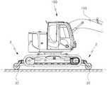
도 1은 본 발명의 바람직한 실시예에 따른 선로주행유닛이 구비된 무한궤도 굴삭기를 도시한 사시도
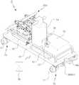
도 2는 도 1의 주요 구성의 확대사시도
도 3은 도 1의 작동상태를 도시한 측도면
도 4는 본 발명의 구성중 선로주행유닛의 다른실시예를 도시한 사시도
도 5는 도 4의 주요 구성의 확대사시도
도 6은 도 4의 작용상태를 도시한 사시도
도 7은 본 발명의 바람직한 실시예에 따른 선로주행유닛이 구비된 무한궤도 굴삭기의 선로 주행시 작동상태를 도시한 도면
도 8은 본 발명의 바람직한 실시예에 따른 선로주행유닛이 구비된 무한궤도 굴삭기의 구난시 작동상태를 도시한 도면
도 9는 본 발명의 선로주행유닛이 구비된 무한궤도 굴삭기에 부가할 수 있는 견인대차를 도시한 사시도
도 10은 도 9의 견인대차를 연결한 상태를 도시한 도면
도 11은 도 9의 견인대차를 이용한 견인작용을 도시한 도면1 is a perspective view showing an endless track excavator equipped with a track driving unit according to a preferred embodiment of the present invention;
Fig. 2 is an enlarged perspective view of the main configuration of Fig.
Fig. 3 is a side view showing the operating state of Fig. 1
4 is a perspective view showing another embodiment of the line travel unit in the structure of the present invention.
Fig. 5 is an enlarged perspective view of the main configuration of Fig.
Fig. 6 is a perspective view showing the operating state of Fig.
FIG. 7 is a view showing an operating state of a trackless traveling excavator having a line traveling unit according to a preferred embodiment of the present invention when traveling on a railway line
8 is a view showing an operating state of a trackless excavator having a track traveling unit according to a preferred embodiment of the present invention,
9 is a perspective view showing a towing truck that can be added to an endless track excavator equipped with a track running unit of the present invention.
Fig. 10 is a view showing a state in which the traction bogie of Fig. 9 is connected
11 is a view showing the pulling action using the traction bogie of Fig. 9
이하 첨부된 도면의 구체적인 실시예에 따라 본 발명을 보다 상세히 설명한다. 본 발명의 구성 실시예에 따른 하기 도면은 구성과 작용효과를 구체적으로 설명하기 위한 실시예로서, 이에 의해 본 발명의 기술적 범위가 좁게 한정되거나 변경되는 것은 아니다. 따라서 이러한 실시예에 기초하여 본 발명의 기술적 사상의 범위 안에서 다양한 변형실시가 가능함은 통상의 기술자에게는 당연하다할 것이다.DETAILED DESCRIPTION OF THE PREFERRED EMBODIMENTS The present invention will be described in more detail with reference to the following embodiments. BRIEF DESCRIPTION OF THE DRAWINGS FIG. 1 is a block diagram showing the configuration of an embodiment of the present invention; FIG. Therefore, it will be apparent to those skilled in the art that various modifications can be made within the scope of the technical idea of the present invention based on these embodiments.
또한, 본 명세서에서 사용되는 기술용어들은 실시예에서의 기능을 고려하여 선택된 용어들로서, 그 용어의 의미는 발명의 구체적인 실시예에 따라 달라질 수 있다. 따라서 후술하는 실시예에서 사용된 용어들은, 본 명세서에 구체적으로 정의된 경우에는 그 정의에 따르며, 구체적인 정의가 없는 경우는 통상의 기술자들이 일반적으로 인식하는 기술용어의 의미로 해석되어야 할 것이다.In addition, the technical terms used in the present specification are terms selected in consideration of functions in the embodiments, and the meaning of the terms may vary according to specific embodiments of the invention. Therefore, the terms used in the following embodiments are defined according to their definitions when they are specifically defined in this specification, and unless otherwise defined, they should be construed in the meanings of technical terms generally recognized by ordinary technicians.
도 1은 본 발명의 바람직한 실시예에 따른 선로주행유닛이 구비된 무한궤도 굴삭기를 도시한 사시도를 나타낸 것이다.1 is a perspective view showing an endless track excavator equipped with a line drive unit according to a preferred embodiment of the present invention.
본 발명에 따른 선로주행유닛이 구비된 무한궤도 굴삭기는 하부프레임(101) 전후측에 무한궤도 굴삭기(100)를 선로에 부상시킨 채로 자체 주행할 수 있도록 형성되는 선로주행유닛(1)과, 무한궤도 굴삭기(100)의 기계 고장시 선로주행유닛(1)을 수동으로 작동하도록 구비되는 구난수단(4)을 포함한다.An endless track excavator provided with a track running unit according to the present invention includes a
도 2를 참조하면, 선로주행유닛(1)은 무한궤도 굴삭기(100)의 전후측 하부프레임(101)에 유압실린더(10)에 의해 승강하는 전측레일차륜(2)과 후측레일차륜(3)으로 구성되며, 상기 전측레일차륜(2) 및 후측레일차륜(3)은 무한궤도 굴삭기(100)의 엔진 및 유압펌프(102)와 연동하도록 설치함으로써 무한궤도 굴삭기(100) 자체적으로 선로를 주행할 수 있도록 구성된다.2, the
상기 전측레일차륜(2)과 후측레일차륜(3)은 동일한 구조 및 구성으로 이루어지며, 무한궤도 굴삭기(100)의 하부프레임(101)에 상하부힌지구(11,12)가 형성된 고정브라켓(13)이 설치되고, 상기 고정브라켓(13)의 하부힌지구(12)에 후단부가 힌지 결합되어 승강하는 작동암(14)이 구비되며, 상기 고정브라켓(13)의 상부힌지구(11)에 후단부가 힌지 결합되고 작동암(14)의 링크(14a)와 피스톤로드(10a)가 힌지 결합되어 작동암(14)을 승강시키는 유압실린더(10)가 구비되고, 상기 작동암(14)의 선단부 하부에 선로를 주행하도록 하는 레일차축(20)이 설치되고, 상기 레일차축(20)을 구동시키도록 체인 연결되는 유압모터(50)가 구비된다.The
이러한 전측레일차륜(2) 및 후측레일차륜(3)은 도 3에 도시된 바와 같이, 유압실린더(10)에 의해 작동암(14)이 하강함과 동시에 레일차축(20)이 선로상으로 안착되면서 무한궤도 굴삭기(100)를 선로에서 이격되도록 부상시킨 후, 유압모터(50)의 구동력으로 레일차축(20)이 선로를 주행하게 된다.As shown in FIG. 3, the
여기서 유압모터(50)는 무한궤도 굴삭기(100) 자체 주행을 위해 굴삭기의 유압펌프(102)와 연동하도록 유압라인을 구성하게 되며, 상기 유압모터(50)와 유압펌프(102) 사이로 유압공급을 제어하기 위한 유압밸브(51)가 형성되고, 상기 유압모터(50)의 구동제어는 무한궤도 굴삭기(100)의 조정실에 의해 제어하도록 구성함으로써, 무한궤도 굴삭기(100) 자체만으로 선로 주행이 가능하게 된다.Here, the
상기 레일차축(20)은 유압모터(50)와 체인 연결되어 구동하는 주행차축(30)으로 구성되며, 상기 주행차축(30)은 작동암(14)의 선단부 하부에 한쌍의 베어링블럭(31)이 양측으로 대향하게 설치되고, 상기 베어링블럭(31)에 양끝에 주행휠(32)이 결합된 피동샤프트(33)가 축설되며, 상기 피동샤프트(33)는 유압모터(50)와 체인 연결된다.The
한편, 상기 레일차축(20)은 주행차축(30)의 전방에 배치되어 무한궤도 굴삭기(100)의 기계 고장으로 인한 구난수단(4)의 사용시 선로에서 견인이 용이하도록 회전이 자유롭도록 하는 견인차축(40)을 더 포함하도록 변형실시할 수 있다.The
도 4 내지 도 6을 참조하면, 견인차축(40)은 작동암(14) 선단부의 주행차축(30) 전측에 한쌍의 베어링블럭(41)이 대향하도록 구비되고, 상기 베어링블럭(41)으로 회전이 자유롭도록 양끝에 견인휠(42)이 결합된 보조샤프트(43)가 축설된다.4 to 6, the
이와 같은 견인차축(40)은 무한궤도 굴삭기(100)의 자체 주행시 주행차축(30)과 선로주행이 안정적이도록 보조하는 역할과 동시에 무한궤도 굴삭기(100)의 구난시 주행차축(30)은 선로에서 이격되도록 부상시키고 회전이 자유로운 견인휠(42)만 선로에 접하도록 하여 견인하게 된다.The
이는 주행휠(32)의 경우 유압모터(50)와 체인 연결된 구조상 회전구동이 제한됨에 따라 견인시 유압모터(50)와 체인 연결을 해제해야 하는 번거로움이 발생된다. 따라서 유압모터(50)에 간섭이 없는 견인차축(40)의 견인휠(42)에 의해 번거로움 없이 견인이 편리하게 이루어지도록 하는 것이다.In the case of the
상기 구난수단(4)은 도 9 및 도 10에 도시된 바와 같이, 무한궤도 굴삭기(100)의 기계고장으로 인해 유압펌프(102)의 작동 불능시 선로주행유닛(1)의 유압실린더(10)를 수동으로 작동시켜 무한궤도 굴삭기(100)의 견인대차(5)에 의해 신속한 견인이 가능하도록 유압실린더(10)에 수동으로 유압을 공급하도록 하는 수동유압펌프(60)가 구비되고, 상기 수동유압펌프(60)에 의해 유압실린더(10)의 작동으로 선로에 안착되는 견인차축(40)의 안전한 주행을 위해 유압실린더(10)의 작동상태를 고정시키기 위한 고정브라켓(13)과 작동암(14) 사이로 설치되는 고정프레임(61)으로 구성된다.9 and 10, when the
상기 고정프레임(61)은 시공 편리성을 위해 고정브라켓(13)과 작동암(14)에 힌지편(62)이 일체 형성되고, 상기 고정프레임(61)의 전후단에 힌지공(63)이 관통되고, 상기 힌지편(62)과 힌지공(63)을 볼트로 체결하게 된다.A
상기 구난수단(4)과 연동하여 무한궤도 굴삭기(100)를 견인하도록 하며 굴삭기의 각종 어테치먼트(200), 구난수단(4) 등을 적재하는 견인대차(5)를 포함할 수 있다.And a
상기 견인대차(5)는 도 9 및 도 10에 도시된 바와 같이 판상의 적재대(70)가 구비되고, 상기 적재대(70) 하부에 양단에 레일휠(71)이 결합된 전륜축(72) 및 후륜축(73)이 형성되고, 상기 적재대(70)에 중간에 무한궤도 굴삭기(100)의 암을 결합하여 거치하도록 하는 암거치대(74)가 형성되며, 상기 적재대(70)의 후단에 전륜축(72) 및 후륜축(73)을 구동시키는 엔진(75) 및 조작부(76)가 형성되며, 상기 조작부(76)의 무선조정이 가능하도록 무선송수신모듈(77) 및 무선컨트롤러(78)를 포함한다.9 and 10, the towing
그리고 상기 견인대차(5)와 선로주행유닛(1)은 상호 체결하여 견인을 위해 견인대차(5)에 견인고리(79a)가 형성되고, 상기 선로주행유닛(1)으로 체결고리 (79)가 형성되며, 상기 견인고리(79a)는 관성작용을 유도하기 위한 장공(79b)이 형성되며, 상기 체결고리(79) 내측으로 견인고리(79a)의 관성 작용시 충돌 완충을 위한 완충스프링(79c)이 형성된다.The
그리고 상기 견인대차(5)는 전륜축(72)을 제동하도록 하는 유압제동부(80)와 상기 유압제동부(80)와 연동하여 선로주행유닛(1)의 견인차축(40)을 관성작용과 동시에 제동하기 위한 연동제동부(90)가 더 설치되며,The
상기 유압제동부(80)는 전륜축(72)에 유압에 의해 작동하는 디스크브레이크(81)가 설치되고, 상기 연동제동부(90)는 견인차축(40)이 유압에 의해 작동하는 보조디스크브레이크(91)가 설치되며, 상기 연동제동부(90)는 유압제동부(80)의 제동시 견인되는 무한궤도 굴삭기(100)가 전방으로 밀리는 관성작용에 의해 연동하면서 제동하도록 구성된다. 즉, 견인고리(79a)의 장공(79b)만큼 무한궤도 굴삭기(100)가 전진함과 동시에 연동제동부(90)가 작동하도록 구성된다.The
한편, 디스크브레이크(81)의 유압펌프 및 마스터실린더에 의한 작용은 통상적인 기술임에 따라 구체적인 구성 및 작용은 생략하기로 한다.Meanwhile, since the operation of the
상기 연동제동부(90)는 관성에 의해 보조디스크브레이크(91)가 작용하도록 견인대차(5)의 견인고리(79) 일측에 푸시로드(92)가 장착되고, 선로주행유닛(1)의 체결고리(79a) 일측에 마스터실린더(93)가 장착되며, 상기 푸시로드(92)와 마스터실린더(93) 사이로 관성작용시 충격을 완화하기 위한 완충스프링(94)이 개재된다.The
이하, 본 발명에 따른 선로주행유닛이 구비된 무한궤도 굴삭기의 작용에 대해 설명하기로 한다.Hereinafter, the operation of the endless track excavator equipped with the track driving unit according to the present invention will be described.
본 발명의 선로주행유닛이 구비된 무한궤도 굴삭기는 무한궤도식의 이송부를 갖는 굴삭기의 선로 주행이 용이하도록 한 것으로, 하부프레임(101) 전후측으로 설치된 선로주행유닛(1)에 의해 무한궤도 굴삭기(100)를 부상시킨 상태로 선로를 주행하게 되며, 이때 선로주행유닛(1)의 주행차축(30)이 유압모터(50)로 구동하도록 하고, 상기 유압모터(50)는 무한궤도 굴삭기(100)의 유압펌프(102)와 연동하도록 구성함으로써, 무한궤도 굴삭기(100)의 조정석에서 선로 주행 운전이 가능하게 된다.The endless track excavator provided with the track running unit of the present invention is an endless track excavator having an endless track type conveying unit for facilitating the running of the excavator. The driving
여기서 선로주행모드시 도 3에 보이는 바와 같이 무한궤도 굴삭기(100)를 선로에 배치시킨 상태에서 선로주행유닛(1)을 하강시키게 된다.Here, in the line running mode, as shown in FIG. 3, the
이때 유압실린더(10)에 의해 작동암(14)이 선로측으로 하강함과 동시에 작동암(14)의 선단부에 설치된 레일차축(20)이 선로상에 안착됨과 동시에 유압실린더(10)의 피스톤로드(10a)의 경사각에 따라 무한궤도 굴삭기(100) 차체는 선로에서 이격되도록 부상시키게 된다.At this time, the
이와 같이 무한궤도 굴삭기(100)가 유압실린더(10)에 의해 상승됨과 동시에 선로상에 레일차축(20)이 접하게 되면, 레일차축(20)을 구성하는 주행차축(30)의 주행휠(32)이 선로에 안착하게 된다.When the
이와 동시에 주행차축(30)의 전측에 견인차축(40)이 더 설치된 경우 도 7에 도시된 바와 같이 견인차축(40)의 견인휠(42)이 주행휠(32)의 전측에서 동시에 안착된 상태로 주행 안전성을 보조적으로 안내하게 된다.At the same time, when the
그리고 무한궤도 굴삭기(100)의 운전석에서 전진주행 조작하게 되면, 유압펌프(102)에서 유압력을 공급함과 동시에 선로주행유닛(1)의 유압모터(50)가 작동되면서 체인 연결된 피동샤프트(33) 및 주행휠(32)이 구동됨에 따라 주행차축(30)에 의해 무한궤도 굴삭기(100) 자체만으로 선로 주행이 이루어지게 된다.When the
이때 견인차축(40)의 견인휠(42)은 회전이 자유롭게 이루어지면서 주행휠(32) 안정적으로 주행하도록 전측에서 안내 지지하게 된다.At this time, the pulling
한편, 무한궤도 굴삭기(100)의 기계 고장시 구난수단(4)을 사용하게 되며, 견인대차(5)로 견인 조치할 수 있도록 구난수단(4)에 의해 수동으로 선로주행유닛(1)을 작동시켜 선로에 무한궤도 굴삭기(100)가 선로 주행이 가능하도록 안착시키게 된다.On the other hand, when the
즉 구난수단(4)의 수동유압펌프(60)를 이용하여 유압실린더(10)를 수동으로 작동시켜 작동암(14)을 하강시키게 되며, 유압실린더(10)의 피스톤로드(10a)를 최대로 작동시켜 경사각도에 따른 주행차축(30)은 선로에서 부상되도록 하면서 도 8에 보이는 바와 같이 견인차축(40)의 견인휠(42)만 선로에 안착시킨 후, 고정프레임(61)으로 고정브라켓(13)과 작동암(14) 사이를 체결하여 유압실린더(10)의 작동상태를 고정하여 유압실린더(10)의 작동오류를 방지하게 된다.That is, the
이와 같이 무한궤도 굴삭기(100)의 기계 고장시 구난수단(4)에 의해 굴삭기(100)를 선로에 안착시키게 되고, 견인휠(42)의 자유 주행에 따른 견인대차(5)로 견인조치가 가능하게 된다.When the
한편, 레일차축(20)이 주행차축(30)으로만 이루어진 경우, 주행차축(30)과 유압모터(50)간에 체인 연결 상태를 해제하여 주행휠(32)이 회전 자유롭도록 조치하게 된다.On the other hand, when the
또한, 무한궤도 굴삭기(100)의 자체 주행시 선로주행유닛(1)의 견인고리(79,79a)에 견인대차(5)를 연결하여 작업장소에 동시 이동하게 된다.In addition, when the
도 11을 참조하면, 견인대차(5)는 선로주행유닛(1)의 견인고리(79) 전후측으로 연결하여 이동함과 동시에 전측으로 연결시 무한궤도 굴삭기(100)의 암(103)을 암거치대(74)에 결합하여 거치한 상태로 주행하게 되며, 적재대(70)에 굴삭기의 어테치먼트(200)와, 구난수단(4)을 적치하여 운송하는 운송차 기능을 제공하게 된다.11, the
이러한 견인대차(5)는 자체 주행이 가능하도록 엔진(75) 및 조작부(76)가 구비되고, 무선송수신모듈(77) 및 무선컨트롤러(78)로 무선조정이 가능하도록 함으로써, 무한궤도 굴삭기(100)의 기계고장에 의한 구난시 견인하기 위한 견인차 역할을 하게 된다.The
이러한 견인대차(5)로 무한궤도 굴삭기(100)를 견인시 구난수단(4)에 의해 무한궤도 굴삭기(100)를 선로에 안착시킨 상태로 견인대차(5)를 전측레일차륜(2) 전방에 배치하여 견인고리(79a)에 선로주행유닛(1)의 체결고리(79)를 핀으로 결합하여 연장하게 되며, 조작부(76)의 간편한 조작에 따라 견인대차(5)의 운전 주행으로 무한궤도 굴삭기(100)를 견인하게 된다. 이때 안전한 견인을 위해 견인대차(5)는 유압제동부(80)의 디스크브레이크(81)가 전륜축(72)을 제동하게 됨과 동시에 관성 작용에 의해 연동제동부(90)가 작동하여 무한궤도 굴삭기(100)를 제동함으로써, 주행방향으로 전진되면서 충돌되는 안전사고를 방지하게 된다.The towing
즉, 유압제동부(80)에 의한 견인대차(5)의 제동과정에서 견인되는 무한궤도 굴삭기(100)가 관성에 의해 견인고리(79a)의 장공(79b)만큼 체결고리(79)가 주행방향으로 전진하게 되고, 이때 푸시로드(92)가 마스터실린더(93)로 완충 삽입되면서 보조디스크브레이크(91)로 유압을 제공하여 견인차축(40)을 제동함으로써, 견인대차(5)와 선로주행유닛(1)이 충돌하는 것을 방지하여 안전한 견인이 이루어지게 된다.That is, the
이상과 같이 본 발명의 상세한 설명에는 본 발명의 가장 바람직한 실시 예에 관하여 설명하였으나, 본 발명의 기술범위에 벗어나지 않는 범위 내에서는 다양한 변형실시도 가능하다 할 것이며, 따라서 본 발명의 보호범위는 상기 실시 예에 한정하여 정해지는 것이 아니라, 후술하는 특허청구범위의 기술들과 이들 기술로부터 균등한 기술수단들에까지 보호범위가 인정되어야 할 것이다.While the present invention has been described with reference to exemplary embodiments, it is to be understood that the invention is not limited to the disclosed exemplary embodiments, but, on the contrary, It should be understood that the scope of the claims is not limited to the examples but covers the scope of the claims and the scope of equivalents thereof.
100:무한궤도 굴삭기 101:하부프레임 102:유압펌프
103:암
1:선로주행유닛 2:전측레일차륜 3:후측레일차륜
10:유압실린더 10a:피스톤로드
11:상부힌지구 12:하부힌지구 13:고정브라켓
14:작동암 14a:링크
20:레일차축
30:주행차축 31:베어링블럭 32:주행휠
33:피동샤프트
40:견인차축 41:베어링블럭 42:견인휠
43:보조샤프트
50:유압모터 51:유압밸브
4:구난수단
60:수동유압펌프 61:고정프레임 62:힌지편
63:힌지공
5:견인대차
70:적재대 71:레일휠 72:전륜축
73:후륜축 74:암거치대 75:엔진
76:조작부 77:무선송수신모듈 78:무선컨트롤러
79:체결고리 79a:견인고리 79b:장공
79c:완충스프링
80:유압제동부 81:디스크브레이크
90:연동제동부 91:보조디스크브레이크 92:푸시로드
93:마스터실린더 94:완충스프링
200:어테치먼트100: endless track excavator 101: lower frame 102: hydraulic pump
103: Cancer
1: Line traveling unit 2: Front rail wheel 3: Rear rail wheel
10:
11: upper hinge region 12: lower hinge region 13: fixing bracket
14: operating
20: Rail axle
30: traveling axle 31: bearing block 32: traveling wheel
33: driven shaft
40: Towing shaft 41: Bearing block 42: Traction wheel
43: auxiliary shaft
50: Hydraulic motor 51: Hydraulic valve
4: Saving means
60: manual hydraulic pump 61: fixed frame 62: hinge piece
63: Hinge ball
5: Towing truck
70: Loading table 71: Rail wheel 72: Front wheel shaft
73: rear wheel axle 74: arm rest 75: engine
76: Operation part 77: Wireless transmission / reception module 78: Wireless controller
79:
79c: Buffer spring
80: Hydraulic braking section 81: Disk brake
90: decoupler unit 91: auxiliary disc brake 92: push rod
93: Master cylinder 94: Buffer spring
200: Attachment
Claims (5)
Translated fromKorean상기 선로주행유닛(1)은 무한궤도 굴삭기(100)의 전후측 하부프레임(101)에 유압실린더(10)에 의해 승강하는 전측레일차륜(2)과 후측레일차륜(3)으로 구성되며,
상기 전측레일차륜(2) 및 후측레일차륜(3)은 하부프레임(101)에 상하부힌지구(11,12)가 형성된 고정브라켓(13)이 설치되고, 상기 고정브라켓(13)의 하부힌지구(12)에 후단부가 힌지 결합되어 승강하는 작동암(14)이 구비되며, 상기 고정브라켓(13)의 상부힌지구(11)에 후단부가 힌지 결합되고 작동암(14)의 링크(14a)와 피스톤로드(10a)가 힌지 결합되어 작동암(14)을 승강시키는 유압실린더(10)가 구비되고, 상기 작동암(14)의 선단부 하부에 선로를 주행하도록 하는 레일차축(20)이 설치되며, 상기 레일차축(20)을 구동시키도록 체인 연결되는 유압모터(50)로 구성되며,
상기 레일차축(20)은 작동암(14)의 선단부 하부에 한쌍의 베어링블럭(31)이 양측으로 대향하도록 설치되고, 상기 베어링블럭(31)에 양끝에 주행휠(32)이 결합된 피동샤프트(33)가 유압모터(50)와 체인 연결된 주행차축(30)과, 상기 주행차축(30)의 전방에 주행휠(32)을 보조하여 선로를 주행하는 견인차축(40)으로 구성되며,
상기 견인차축(40)은 작동암(14) 선단부의 주행차축(30) 전측으로 한쌍의 베어링블럭(41)이 대향하도록 구비되고, 상기 베어링블럭(41)의 양끝에 견인휠(42)이 결합된 보조샤프트(43)가 회전이 자유롭도록 축설되며,
상기 유압모터(50)는 무한궤도 굴삭기(100)의 유압펌프(102)와 연동하도록 유압라인을 구성하여 무한궤도 굴삭기(100)가 자체적으로 선로 주행이 가능하도록 구성한 것을 특징으로 하는 선로주행유닛이 구비된 무한궤도 굴삭기.
The track traveling unit 1 is constructed on the front and rear sides of the lower frame 101 of the endless track excavator 100 so that the endless track excavator 100 can run on its own while floating on the track,
The track traveling unit 1 is constituted by front rail wheels 2 and rear rail wheels 3 which are raised and lowered by hydraulic cylinders 10 on the front and rear lower frames 101 of the endless track excavator 100,
The front rail 2 and the rear rail 3 are provided with a fixing bracket 13 having upper and lower hinge portions 11 and 12 formed on a lower frame 101, A rear end portion of the operation arm 14 is hinged to the upper hinge region 11 of the fixing bracket 13 and the link 14a of the operation arm 14 A hydraulic cylinder 10 in which the piston rod 10a is hinged to raise and lower the operation arm 14 is provided and a rail axle 20 is provided below the tip of the operation arm 14 to run the line, And a hydraulic motor (50) chain-connected to drive the rail axle (20)
The rail axle 20 is provided with a pair of bearing blocks 31 on both sides so as to be opposed to the lower ends of the front ends of the actuating arms 14 and a driven shaft 32, A driving axle 30 connected to the hydraulic motor 50 in a chain and a traction axle 40 running on the line to assist the driving wheel 32 in front of the driving axle 30,
A pair of bearing blocks 41 are provided on the front side of the driving axle 30 at the front end of the operating arm 14 so that the towing wheel 40 is coupled to both ends of the bearing block 41, The auxiliary shaft 43 is formed so as to be freely rotatable,
Wherein the hydraulic motor (50) constitutes a hydraulic line so as to be interlocked with the hydraulic pump (102) of the endless track excavator (100) so that the endless track excavator (100) Equipped endless track excavator.
선로주행유닛(1)은 무한궤도 굴삭기(100)의 기계 고장시 선로주행유닛(1)을 수동으로 작동하기 위한 구난수단(4)을 더 포함하며,
상기 구난수단(4)은 유압실린더(10)를 수동으로 작동시키도록 구비되는 수동유압펌프(60)와,
구난수단(4)을 사용시 유압실린더(10)를 최대 작동시켜 주행휠(32)은 선로에 부상시키고 견인차축(40)의 견인휠(42)만 선로에 안착시킨 상태를 고정시키 위해 고정브라켓(13)과 작동암(14) 사이로 결합하는 고정프레임(61)으로 구성됨을 특징으로 하는 선로주행유닛이 구비된 무한궤도 굴삭기.
The method according to claim 1,
The line traveling unit 1 further includes a recovery means 4 for manually operating the line traveling unit 1 in the event of a mechanical failure of the endless track excavator 100,
The recovery means 4 includes a manual hydraulic pump 60 for manually actuating the hydraulic cylinder 10,
The hydraulic cylinder 10 is operated to the maximum when the recovery means 4 is used so that the traveling wheel 32 floats on the track and the fixing bracket 13. The endless track excavator as set forth in claim 1, wherein the fixed frame (61) is coupled to the operation arm (14).
선로주행유닛(1)은 전후측으로 체결고리(79)가 형성되고, 상기 체결고리(79)와 연장 연결하여 구난수단(4) 및 무한궤도 굴삭기(100)의 어테치먼트(200)를 적치시킨 후 이송하는 역할과 무한궤도 굴삭기(100)의 기계 고장에 의한 구난시 선로를 이용하여 견인하는 역할 겸하는 견인대차(5)를 더 포함하며,
상기 견인대차(5)는 전후측으로 장공(79b)이 형성된 견인고리(79a)가 형성된 판상의 적재대(70)와, 상기 적재대(70) 하부에 양단에 레일휠(71)이 결합된 전륜축(72) 및 후륜축(73)이 형성되고, 상기 적재대(70)에 중간에 무한궤도 굴삭기(100)의 암을 결합하여 거치하도록 하는 암거치대(74)가 형성되며, 상기 적재대(70)의 후단에 전륜축(72) 및 후륜축(73)을 구동시키는 엔진(75) 및 조작부(76)가 형성되며, 상기 조작부(76)의 무선조정이 가능하도록 무선송수신모듈(77) 및 무선컨트롤러(78)로 구성된 것을 특징으로 하는 선로주행유닛이 구비된 무한궤도 굴삭기.
The method of claim 3,
The track traveling unit 1 is provided with a fastening ring 79 on the front and rear sides and connected to the fastening ring 79 to connect the retaining means 4 and the attachments 200 of the endless track excavator 100 And a traction bogie (5) serving also as a tractor for traction by using a recovery line due to a mechanical failure of the endless track excavator (100)
The towing carriage 5 is provided with a plate-shaped table 70 on which a pulling ring 79a with a long hole 79b is formed on the front and rear sides, A shaft 72 and a rear wheel shaft 73 are formed and a rocker arm base 74 is formed on the rocker arm 70 so as to engage and lock the arm of the endless track excavator 100, An engine 75 and an operating portion 76 for driving the front wheel shaft 72 and the rear wheel shaft 73 are formed at the rear end of the operating portion 76 and the wireless transmitting / And a wireless controller (78). ≪ Desc / Clms Page number 24 >
상기 견인대차(5)는 전륜축(72)으로 유압으로 제동하는 디스크브레이크(81)로 이루어진 유압제동부(80)가 구성되고,
상기 유압제동부(80)의 제동과 동시에 선로주행유닛(1)이 견인대차(5)쪽으로 밀려지는 관성작용을 이용하여 견인차축(40)을 제동시키기 위한 연동제동부(90)를 포함하며,
상기 연동제동부(90)는 견인차축(40)에 보조디스크브레이크(91)가 장착되고,
상기 보조디스크브레이크(91)는 관성작용에 의해 유압력이 작용하도록 견인대차(5)에 푸시로드(92)가 형성되고, 선로주행유닛(1)의 선단에 마스터실린더(93)가 장착되며, 상기 푸시로드(92)와 마스터실린더(93) 사이로 관성작용시 충격을 완화하기 위한 완충스프링(94)이 개재되도록 구성됨을 특징으로 하는 선로주행유닛이 구비된 무한궤도 굴삭기.The method of claim 4,
The traction bogie 5 is constituted by a hydraulic braking portion 80 composed of a disk brake 81 that brakes with hydraulic pressure on the front wheel shaft 72,
(90) for braking the tow shaft (40) by using an inertial action in which the line running unit (1) is pushed toward the trailer (5) simultaneously with the braking of the hydraulic braking unit (80)
The decoupling member 90 is mounted on the towing shaft 40 with an auxiliary disc brake 91,
The auxiliary disk brake 91 is provided with a push rod 92 on the traction bogie 5 so that hydraulic pressure acts on the auxiliary disk brake 91. The master cylinder 93 is mounted on the tip of the line travel unit 1, And a buffer spring (94) is interposed between the push rod (92) and the master cylinder (93) to mitigate an impact in inertia action.
Priority Applications (1)
| Application Number | Priority Date | Filing Date | Title |
|---|---|---|---|
| KR1020180067893AKR101908687B1 (en) | 2018-06-14 | 2018-06-14 | Caterpillar excavator with line drive unit |
Applications Claiming Priority (1)
| Application Number | Priority Date | Filing Date | Title |
|---|---|---|---|
| KR1020180067893AKR101908687B1 (en) | 2018-06-14 | 2018-06-14 | Caterpillar excavator with line drive unit |
Publications (1)
| Publication Number | Publication Date |
|---|---|
| KR101908687B1true KR101908687B1 (en) | 2018-10-16 |
Family
ID=64132757
Family Applications (1)
| Application Number | Title | Priority Date | Filing Date |
|---|---|---|---|
| KR1020180067893AActiveKR101908687B1 (en) | 2018-06-14 | 2018-06-14 | Caterpillar excavator with line drive unit |
Country Status (1)
| Country | Link |
|---|---|
| KR (1) | KR101908687B1 (en) |
Cited By (13)
| Publication number | Priority date | Publication date | Assignee | Title |
|---|---|---|---|---|
| KR102037442B1 (en)* | 2018-11-21 | 2019-10-28 | (주)케미우스코리아 | Boring machine for reinforcing multiple layered embanked bed of rail |
| CN110406452A (en)* | 2019-09-06 | 2019-11-05 | 天津清研科技发展有限公司 | A kind of material heap tarpaulin lays vehicle |
| KR102129047B1 (en) | 2020-03-17 | 2020-07-08 | 주식회사 한일엔지니어링 | Wetland Excavator |
| KR20210002211A (en) | 2019-06-27 | 2021-01-07 | 김준연 | Caterpillar excavator |
| KR20210002210A (en) | 2019-06-27 | 2021-01-07 | 김준연 | Caterpillar excavator |
| CN112746646A (en)* | 2021-01-15 | 2021-05-04 | 广西玉柴重工有限公司 | Chassis mechanism of highway and railway excavator |
| CN113460177A (en)* | 2021-08-09 | 2021-10-01 | 山河智能装备股份有限公司 | Wheel-track dual-purpose multifunctional belt opener |
| CN115126494A (en)* | 2022-06-13 | 2022-09-30 | 中煤科工机器人科技有限公司 | Tunnel repairing machine |
| KR102548619B1 (en)* | 2022-10-19 | 2023-06-28 | 대동이앤티(주) | Apparatus for rear rail unit of the road-rail vehicles |
| KR20230143482A (en) | 2022-04-05 | 2023-10-12 | 한솔기계중기 주식회사 | Excavator having adjustable width for track |
| CN117345707A (en)* | 2023-04-10 | 2024-01-05 | 济宁山科工程机械有限公司 | Quick walking hydraulic system of excavator |
| KR20240054551A (en)* | 2022-10-19 | 2024-04-26 | 대동이앤티(주) | Apparatus for front rail unit of the road-rail vehicles |
| CN118928569A (en)* | 2024-10-12 | 2024-11-12 | 长春汽车工业高等专科学校 | A wheel-track conversion rescue vehicle for disaster relief |
Citations (2)
| Publication number | Priority date | Publication date | Assignee | Title |
|---|---|---|---|---|
| JPH10236121A (en)* | 1997-02-25 | 1998-09-08 | Niigata Kobelco Kenki Kk | Working machine for track |
| KR101654430B1 (en) | 2014-11-26 | 2016-09-05 | 임우근 | Excavator for railroad repair with emergency towing device |
- 2018
- 2018-06-14KRKR1020180067893Apatent/KR101908687B1/enactiveActive
Patent Citations (2)
| Publication number | Priority date | Publication date | Assignee | Title |
|---|---|---|---|---|
| JPH10236121A (en)* | 1997-02-25 | 1998-09-08 | Niigata Kobelco Kenki Kk | Working machine for track |
| KR101654430B1 (en) | 2014-11-26 | 2016-09-05 | 임우근 | Excavator for railroad repair with emergency towing device |
Cited By (16)
| Publication number | Priority date | Publication date | Assignee | Title |
|---|---|---|---|---|
| KR102037442B1 (en)* | 2018-11-21 | 2019-10-28 | (주)케미우스코리아 | Boring machine for reinforcing multiple layered embanked bed of rail |
| KR20210002211A (en) | 2019-06-27 | 2021-01-07 | 김준연 | Caterpillar excavator |
| KR20210002210A (en) | 2019-06-27 | 2021-01-07 | 김준연 | Caterpillar excavator |
| CN110406452B (en)* | 2019-09-06 | 2024-04-12 | 天津清研科技发展有限公司 | Tarpaulin placing vehicle for material stack |
| CN110406452A (en)* | 2019-09-06 | 2019-11-05 | 天津清研科技发展有限公司 | A kind of material heap tarpaulin lays vehicle |
| KR102129047B1 (en) | 2020-03-17 | 2020-07-08 | 주식회사 한일엔지니어링 | Wetland Excavator |
| CN112746646A (en)* | 2021-01-15 | 2021-05-04 | 广西玉柴重工有限公司 | Chassis mechanism of highway and railway excavator |
| CN113460177A (en)* | 2021-08-09 | 2021-10-01 | 山河智能装备股份有限公司 | Wheel-track dual-purpose multifunctional belt opener |
| KR20230143482A (en) | 2022-04-05 | 2023-10-12 | 한솔기계중기 주식회사 | Excavator having adjustable width for track |
| CN115126494A (en)* | 2022-06-13 | 2022-09-30 | 中煤科工机器人科技有限公司 | Tunnel repairing machine |
| KR102548619B1 (en)* | 2022-10-19 | 2023-06-28 | 대동이앤티(주) | Apparatus for rear rail unit of the road-rail vehicles |
| KR20240054551A (en)* | 2022-10-19 | 2024-04-26 | 대동이앤티(주) | Apparatus for front rail unit of the road-rail vehicles |
| KR102686136B1 (en) | 2022-10-19 | 2024-07-22 | 대동이앤티(주) | Apparatus for front rail unit of the road-rail vehicles |
| CN117345707A (en)* | 2023-04-10 | 2024-01-05 | 济宁山科工程机械有限公司 | Quick walking hydraulic system of excavator |
| CN117345707B (en)* | 2023-04-10 | 2024-05-31 | 济宁山科工程机械有限公司 | Quick walking hydraulic system of excavator |
| CN118928569A (en)* | 2024-10-12 | 2024-11-12 | 长春汽车工业高等专科学校 | A wheel-track conversion rescue vehicle for disaster relief |
Similar Documents
| Publication | Publication Date | Title |
|---|---|---|
| KR101908687B1 (en) | Caterpillar excavator with line drive unit | |
| US5868078A (en) | Road and rail vehicle using rail wheel drive and apparatus | |
| CN103332081B (en) | Road and rail dual-purpose tractor | |
| US10696113B2 (en) | Railcar-mover vehicle | |
| EA024012B1 (en) | IMPROVED INTERMODAL RAILWAY VEHICLE FOR FORMING A TRAIN | |
| JP2004525030A (en) | Combination traveling vehicles that can travel on various traveling paths | |
| KR101654430B1 (en) | Excavator for railroad repair with emergency towing device | |
| US20090194000A1 (en) | Road and rail vehicle with pivotable axle and associated methods | |
| CN87104292A (en) | Improved railway train consisting of road trailers and parts therefor | |
| EP0642428B1 (en) | Convertible railway-roadway vehicle and method of use | |
| US6786158B2 (en) | Railcar-moving vehicle with load-shifting device | |
| CN201062187Y (en) | Coal mine down-hole tunnel mono-rail hoister | |
| US5619931A (en) | Road and rail using rail wheel drive and apparatus | |
| US4843973A (en) | Railcar moving vehicles | |
| CN102729744A (en) | Highway track hydraulic-tractor | |
| US3399633A (en) | Convertible rail-highway tractor | |
| KR20130029518A (en) | Right-angle direction road-rail tow truck | |
| JP2007055351A (en) | Railroad vehicle with derailment restoring device | |
| US6598538B2 (en) | Rail wheel stop mechanism for road/rail vehicle | |
| US6324993B1 (en) | Hydraulic load-shifting device for drawbar | |
| US11396254B2 (en) | Railcar-mover vehicle | |
| JP4187961B2 (en) | Dual-mode vehicle transportation system that can be used for both railway and road | |
| KR20230169760A (en) | Moving device for rigid catenary system | |
| CN220996048U (en) | Loader platform tractor for railway | |
| WO2003051655A1 (en) | A road and railway going vehicle |
Legal Events
| Date | Code | Title | Description |
|---|---|---|---|
| PA0109 | Patent application | Patent event code:PA01091R01D Comment text:Patent Application Patent event date:20180614 | |
| PA0201 | Request for examination | ||
| PA0302 | Request for accelerated examination | Patent event date:20180626 Patent event code:PA03022R01D Comment text:Request for Accelerated Examination Patent event date:20180614 Patent event code:PA03021R01I Comment text:Patent Application | |
| PE0902 | Notice of grounds for rejection | Comment text:Notification of reason for refusal Patent event date:20180807 Patent event code:PE09021S01D | |
| E701 | Decision to grant or registration of patent right | ||
| PE0701 | Decision of registration | Patent event code:PE07011S01D Comment text:Decision to Grant Registration Patent event date:20181001 | |
| GRNT | Written decision to grant | ||
| PR0701 | Registration of establishment | Comment text:Registration of Establishment Patent event date:20181010 Patent event code:PR07011E01D | |
| PR1002 | Payment of registration fee | Payment date:20181011 End annual number:3 Start annual number:1 | |
| PG1601 | Publication of registration | ||
| PR1001 | Payment of annual fee | Payment date:20211012 Start annual number:4 End annual number:4 | |
| PR1001 | Payment of annual fee | Payment date:20220928 Start annual number:5 End annual number:5 | |
| PR1001 | Payment of annual fee | Payment date:20231010 Start annual number:6 End annual number:6 | |
| PR1001 | Payment of annual fee | Payment date:20241007 Start annual number:7 End annual number:7 |