KR101908132B1 - Remote Keyless Entry Unit which is installed on Mobile phone and Method for Controlling Smart Key Electronic Controller Unit thereof - Google Patents
Remote Keyless Entry Unit which is installed on Mobile phone and Method for Controlling Smart Key Electronic Controller Unit thereofDownload PDFInfo
- Publication number
- KR101908132B1 KR101908132B1KR1020110090117AKR20110090117AKR101908132B1KR 101908132 B1KR101908132 B1KR 101908132B1KR 1020110090117 AKR1020110090117 AKR 1020110090117AKR 20110090117 AKR20110090117 AKR 20110090117AKR 101908132 B1KR101908132 B1KR 101908132B1
- Authority
- KR
- South Korea
- Prior art keywords
- mobile phone
- antenna
- smart key
- rke
- microcomputer
- Prior art date
- Legal status (The legal status is an assumption and is not a legal conclusion. Google has not performed a legal analysis and makes no representation as to the accuracy of the status listed.)
- Active
Links
Images

Classifications
- E—FIXED CONSTRUCTIONS
- E05—LOCKS; KEYS; WINDOW OR DOOR FITTINGS; SAFES
- E05B—LOCKS; ACCESSORIES THEREFOR; HANDCUFFS
- E05B81/00—Power-actuated vehicle locks
- E05B81/54—Electrical circuits
- E05B81/56—Control of actuators
- E05B81/60—Control of actuators using pulse control, e.g. pulse-width modulation
- B—PERFORMING OPERATIONS; TRANSPORTING
- B60—VEHICLES IN GENERAL
- B60R—VEHICLES, VEHICLE FITTINGS, OR VEHICLE PARTS, NOT OTHERWISE PROVIDED FOR
- B60R25/00—Fittings or systems for preventing or indicating unauthorised use or theft of vehicles
- B—PERFORMING OPERATIONS; TRANSPORTING
- B60—VEHICLES IN GENERAL
- B60R—VEHICLES, VEHICLE FITTINGS, OR VEHICLE PARTS, NOT OTHERWISE PROVIDED FOR
- B60R25/00—Fittings or systems for preventing or indicating unauthorised use or theft of vehicles
- B60R25/01—Fittings or systems for preventing or indicating unauthorised use or theft of vehicles operating on vehicle systems or fittings, e.g. on doors, seats or windscreens
- B60R25/04—Fittings or systems for preventing or indicating unauthorised use or theft of vehicles operating on vehicle systems or fittings, e.g. on doors, seats or windscreens operating on the propulsion system, e.g. engine or drive motor
- B—PERFORMING OPERATIONS; TRANSPORTING
- B60—VEHICLES IN GENERAL
- B60R—VEHICLES, VEHICLE FITTINGS, OR VEHICLE PARTS, NOT OTHERWISE PROVIDED FOR
- B60R25/00—Fittings or systems for preventing or indicating unauthorised use or theft of vehicles
- B60R25/10—Fittings or systems for preventing or indicating unauthorised use or theft of vehicles actuating a signalling device
- B—PERFORMING OPERATIONS; TRANSPORTING
- B60—VEHICLES IN GENERAL
- B60R—VEHICLES, VEHICLE FITTINGS, OR VEHICLE PARTS, NOT OTHERWISE PROVIDED FOR
- B60R25/00—Fittings or systems for preventing or indicating unauthorised use or theft of vehicles
- B60R25/20—Means to switch the anti-theft system on or off
- B60R25/24—Means to switch the anti-theft system on or off using electronic identifiers containing a code not memorised by the user
- E—FIXED CONSTRUCTIONS
- E05—LOCKS; KEYS; WINDOW OR DOOR FITTINGS; SAFES
- E05B—LOCKS; ACCESSORIES THEREFOR; HANDCUFFS
- E05B47/00—Operating or controlling locks or other fastening devices by electric or magnetic means
- E—FIXED CONSTRUCTIONS
- E05—LOCKS; KEYS; WINDOW OR DOOR FITTINGS; SAFES
- E05B—LOCKS; ACCESSORIES THEREFOR; HANDCUFFS
- E05B49/00—Electric permutation locks; Circuits therefor ; Mechanical aspects of electronic locks; Mechanical keys therefor
- E—FIXED CONSTRUCTIONS
- E05—LOCKS; KEYS; WINDOW OR DOOR FITTINGS; SAFES
- E05B—LOCKS; ACCESSORIES THEREFOR; HANDCUFFS
- E05B53/00—Operation or control of locks by mechanical transmissions, e.g. from a distance
- H—ELECTRICITY
- H04—ELECTRIC COMMUNICATION TECHNIQUE
- H04B—TRANSMISSION
- H04B1/00—Details of transmission systems, not covered by a single one of groups H04B3/00 - H04B13/00; Details of transmission systems not characterised by the medium used for transmission
- H04B1/02—Transmitters
- H04B1/03—Constructional details, e.g. casings, housings
- H04B1/034—Portable transmitters
- H—ELECTRICITY
- H04—ELECTRIC COMMUNICATION TECHNIQUE
- H04B—TRANSMISSION
- H04B1/00—Details of transmission systems, not covered by a single one of groups H04B3/00 - H04B13/00; Details of transmission systems not characterised by the medium used for transmission
- H04B1/38—Transceivers, i.e. devices in which transmitter and receiver form a structural unit and in which at least one part is used for functions of transmitting and receiving
- H—ELECTRICITY
- H04—ELECTRIC COMMUNICATION TECHNIQUE
- H04Q—SELECTING
- H04Q9/00—Arrangements in telecontrol or telemetry systems for selectively calling a substation from a main station, in which substation desired apparatus is selected for applying a control signal thereto or for obtaining measured values therefrom
Landscapes
- Engineering & Computer Science (AREA)
- Mechanical Engineering (AREA)
- Computer Networks & Wireless Communication (AREA)
- Signal Processing (AREA)
- Lock And Its Accessories (AREA)
- Telephone Function (AREA)
Abstract
Translated fromKoreanDescription
Translated fromKorean본 발명은 스마트키 시스템에 관한 것으로서, 더 구체적으로는 휴대폰을 이용하여 차량 스마트키 ECU를 제어할 수 있는 휴대폰에 장착되는 RKE 장치 및 그의 스마트키 ECU 제어 방법에 관한 것이다.The present invention relates to a smart key system, and more particularly, to an RKE device mounted on a mobile phone capable of controlling a vehicle smart key ECU by using a mobile phone and a smart key ECU control method thereof.
일반적으로, 차량용 스마트키 시스템은 스마트 키를 소지한 사용자가 차량에 근접하여 차량의 특정부분을 터치하면, 도어잠금/도어개방/시동/패닉해제를 제어한다.Generally, a smart key system for a vehicle controls door lock / door open / start / panic release when a user having a smart key touches a specific portion of the vehicle in proximity to the vehicle.
그런데, 스마트 키는 단지 차량 제어에만 활용되므로, 사용자가 그외의 시간에 스마트 키를 늘 휴대하는 것은 다소 불편한 일이고, 늘 관심을 두는 물품이 아니어서 분실 위험도 높은 편이다.However, since the smart key is used only for vehicle control, it is somewhat uncomfortable for the user to carry the smart key at other times, and the risk of losing is high because the user is not always interested.
이를 개선하고자, SK 텔레콤은 스마트 키 블록을 부가한 휴대폰을 제공하고, 차량에 CDMA 모듈을 부가하면, 이동통신망(2G망, 3G망)을 통해 스마트키 서비스를 이용할 수 있도록 지원하고 있다.In order to improve this, SK Telecom has provided a mobile phone with a smart key block, and when it adds a CDMA module to a vehicle, it supports smart key service through a mobile communication network (2G network, 3G network).
그런데, 종래의 스마트키 서비스를 제공하는 휴대폰은 이동통신망을 이용해 별도로 통신비용을 부담해야 했고, 통신 사업자(SK 텔레콤, KT, LG 텔레콤)를 변경할 경우, 차량의 CDMA 모듈도 교체해야 했다.However, a conventional mobile phone providing a smart key service would have to pay a separate communication cost by using a mobile communication network, and when a carrier (SK Telecom, KT, or LG Telecom) was changed, the CDMA module of the vehicle had to be replaced.
본 발명은 전술한 바와 같은 기술적 배경에서 안출된 것으로서, 휴대폰의 안테나를 통해 차량에 구비된 스마트키 ECU에 스마트키 기능을 요청할 수 있는 휴대폰에 장착되는 RKE 장치 및 그의 스마트키 ECU 제어 방법을 제공하는 것을 그 목적으로 한다.The present invention provides a smart key ECU control method for an RKE device mounted on a mobile phone capable of requesting a smart key function to a smart key ECU provided in a vehicle through an antenna of a mobile phone, For that purpose.
본 발명의 일면에 따른 RKE 장치는, RKE(Remote Keyless Entry) 서비스용 애플리케이션이 설치된 휴대폰의 연결부에 장착되면, 상기 휴대폰의 마이컴, 안테나, 전원 및 그라운드와 접속되는 접속부; 상기 휴대폰의 마이컴으로부터 복수의 차량 스마트키 기능 중, 사용자가 상기 애플리케이션을 통해 요청한 적어도 하나의 기능의 실행을 요청받으면, 상기 적어도 하나의 기능에 대응하는 제어신호를 출력하는 RKE 마이컴; 상기 차량에 구비된 스마트키 ECU의 통신 주파수를 생성하는 오실레이터(Oscillator); 상기 안테나를 상기 통신 주파수에 매칭하는 제1 매칭회로; 및 상기 제어신호를 상기 통신 주파수에 실어, 접속된 상기 안테나를 통해 상기 스마트키 ECU로 송신하는 RF 통신부를 포함하는 것을 특징으로 한다.An RKE apparatus according to an aspect of the present invention includes: a connection unit connected to a microcomputer, an antenna, a power source, and a ground of the mobile phone when the RKE apparatus is installed in a connection unit of a mobile phone equipped with an application for an RKE (Remote Keyless Entry) service; An RKE microcomputer for outputting a control signal corresponding to the at least one function when a plurality of vehicle smart key functions requested by the user from the microcomputer of the cellular phone are requested to execute at least one function requested by the user through the application; An oscillator for generating a communication frequency of the smart key ECU provided in the vehicle; A first matching circuit for matching the antenna to the communication frequency; And an RF communication unit for transmitting the control signal to the smart key ECU through the antenna connected to the communication frequency.
본 발명의 다른 면에 따른 오실레이터(Oscillator) 및 제1 매칭회로를 포함하는 RKE(Remote Keyless Entry) 장치의 스마트키 ECU 제어 방법은, RKE 서비스용 애플리케이션, 마이컴 및 안테나를 포함하는 휴대폰으로부터 전원이 공급되면, 상기 오실레이터에 의해 상기 스마트키 ECU의 통신 주파수를 생성하는 단계; 상기 휴대폰의 마이컴으로부터 복수의 차량 스마트키 기능 중, 사용자가 상기 애플리케이션을 통해 요청한 적어도 하나의 기능의 실행을 요청받으면, 상기 적어도 하나의 기능에 대응하는 제어신호를 출력하는 단계; 및 상기 제어신호를 상기 통신 주파수에 실어, 상기 제1 매칭회로에 의해 상기 통신 주파수에 매칭된 상기 안테나를 통해 상기 스마트키 ECU로 송신하는 단계를 포함하는 것을 특징으로 한다.A smart key ECU control method of an RKE (Remote Keyless Entry) device including an oscillator and a first matching circuit according to another aspect of the present invention is a smart key ECU control method in which power is supplied from a mobile phone including an RKE service application, Generating a communication frequency of the smart key ECU by the oscillator; Outputting a control signal corresponding to the at least one function when the user is requested to execute at least one function requested by the user through the application among the plurality of vehicle smart key functions from the microcomputer of the cellular phone; And transmitting the control signal to the smart key ECU through the antenna matching the communication frequency by the first matching circuit by placing the control signal on the communication frequency.
본 발명에 따르면, 휴대폰에 애플리케이션을 설치하고, 애플리케이션을 통해 RKE 장치로 스마트키 ECU의 특정기능의 실행을 요청하여 스마트키 ECU를 제어함에 따라 스마트키 ECU의 소스가 휴대폰에 노출되는 것을 방지할 수 있으며, 애플리케이션을 설치하면 다양한 휴대폰에 적용될 수 있다.According to the present invention, it is possible to prevent the source of the smart key ECU from being exposed to the mobile phone by installing the application in the mobile phone and controlling the smart key ECU by requesting the RKE device to execute the specific function of the smart key ECU through the application And can be applied to a variety of mobile phones by installing applications.
또한, 본 발명은 휴대폰의 인터페이스 및 안테나를 사용하되, RKE 장치에 의해 휴대폰 안테나를 스마트키 ECU의 통신 주파수에 매칭시켜, 종래의 스마트키 ECU의 통신 주파수를 이용하므로, 차량의 스마트키 ECU를 별도로 변경시킬 필요가 없으며, 종래의 휴대폰을 이용하는 RKE처럼 통신비용에 대한 부담이 없다.Further, the present invention uses the interface of the mobile phone and the antenna, and uses the communication frequency of the conventional smart key ECU by matching the cellular phone antenna with the communication frequency of the smart key ECU by the RKE device, There is no need to change and there is no burden on the communication cost as in the case of the RKE using the conventional mobile phone.
도 1은 본 발명의 실시예에 따른 RKE 장치가 장착되는 휴대폰을 도시한 구성도.
도 2는 본 발명의 실시예에 따른 RKE 장치를 세부적으로 도시한 구성도.
도 3은 본 발명의 실시예에 따른 스마트키 ECU 제어 방법을 도시한 흐름도.BRIEF DESCRIPTION OF THE DRAWINGS FIG. 1 is a block diagram showing a mobile phone in which an RKE device according to an embodiment of the present invention is mounted; FIG.
BACKGROUND OF THE INVENTION 1. Field of the Invention [0001] The present invention relates to an RKE apparatus.
3 is a flowchart illustrating a smart key ECU control method according to an embodiment of the present invention.
본 발명의 이점 및 특징, 그리고 그것들을 달성하는 방법은 첨부되는 도면과 함께 상세하게 후술되어 있는 실시예들을 참조하면 명확해질 것이다. 그러나 본 발명은 이하에서 개시되는 실시예들에 한정되는 것이 아니라 서로 다른 다양한 형태로 구현될 것이며, 단지 본 실시예들은 본 발명의 개시가 완전하도록 하며, 본 발명이 속하는 기술분야에서 통상의 지식을 가진 자에게 발명의 범주를 완전하게 알려주기 위해 제공되는 것이며, 본 발명은 청구항의 범주에 의해 정의될 뿐이다. 한편, 본 명세서에서 사용된 용어는 실시예들을 설명하기 위한 것이며 본 발명을 제한하고자 하는 것은 아니다. 본 명세서에서, 단수형은 문구에서 특별히 언급하지 않는 한 복수형도 포함한다. 명세서에서 사용되는 "포함한다(comprises)" 및/또는 "포함하는(comprising)"은 언급된 구성소자, 단계, 동작 및/또는 소자는 하나 이상의 다른 구성소자, 단계, 동작 및/또는 소자의 존재 또는 추가를 배제하지 않는다.BRIEF DESCRIPTION OF THE DRAWINGS The advantages and features of the present invention, and the manner of achieving them, will be apparent from and elucidated with reference to the embodiments described hereinafter in conjunction with the accompanying drawings. The present invention may, however, be embodied in many different forms and should not be construed as being limited to the embodiments set forth herein. Rather, these embodiments are provided so that this disclosure will be thorough and complete, and will fully convey the scope of the invention to those skilled in the art. Is provided to fully convey the scope of the invention to those skilled in the art, and the invention is only defined by the scope of the claims. It is to be understood that the terminology used herein is for the purpose of describing particular embodiments only and is not intended to be limiting of the invention. In the present specification, the singular form includes plural forms unless otherwise specified in the specification. As used herein, the terms " comprises, " and / or "comprising" refer to the presence or absence of one or more other components, steps, operations, and / Or additions.
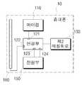
이제 본 발명의 바람직한 실시예에 대하여 첨부한 도면을 참조하여 상세히 설명하기로 한다. 도 1은 본 발명의 실시예에 따른 RKE 장치가 장착되는 휴대폰을 도시한 구성도이다.DETAILED DESCRIPTION OF THE PREFERRED EMBODIMENTS Hereinafter, preferred embodiments of the present invention will be described in detail with reference to the accompanying drawings. 1 is a block diagram showing a mobile phone on which an RKE device according to an embodiment of the present invention is mounted.
도 1에 도시된 바와 같이, 본 발명의 실시예에 따른 휴대폰(10)은 연결부(121~124), 안테나(160), 제2 매칭회로(130), 마이컴(110) 및 전원부(150)를 포함하며, RKE 서비스용 애플리케이션(이하, "애플리케이션"이라고 함)이 설치된다.1, a
RKE 서비스용 애플리케이션은 차량 서비스사에 의해 제공될 수 있으며, 휴대폰(10) 생산시부터 내장될 수 있으며, 앱 형태로 설치될 수 있다.The RKE service application may be provided by a vehicle service company, and may be embedded from the time of manufacturing the
연결부(121~124)는 마이컴(110)과 연결된 제2 데이터 단자(121), 안테나(160)와 연결된 제2 안테나 단자(122), 전원부(150)와 연결된 제2 전원 단자(123) 및 휴대폰의 그라운드와 연결된 제2 그라운드 단자(124)를 포함한다.The
연결부(121~124)는 접속부(221~224)가 장착되면(즉, RKE 장치(20)가 장착되면), 접속부(221~224)의 제1 데이터 단자(221), 제1 안테나 단자(222), 제1 전원 단자(223) 및 제1 그라운드 단자(224)에 각기 연결되는 제2 데이터 단자(121), 제2 안테나 단자(122), 제2 전원 단자(123) 및 제2 그라운드 단자(124)를 포함한다.The
예컨대, RKE 장치(20)가 카드 형태로 구성되어, 연결부(121~124)에 끼워져 고정될 경우, 연결부(121~124)는 접속부(221~224)의 각 단자와 연결되는 소켓 형태로 구성될 수 있다.For example, when the
안테나(160)는 제2 매칭회로(130)에 의하여 이동통신 서비스를 위한 이동통신 주파수(예컨대, 800~900MHz, 1~2Hz)에 매칭되어, 이동통신 서비스를 제공할 때 이동통신 데이터를 송수신한다.The
안테나(160)는 RKE 장치(20)에 의해 RKE 서비스를 제공할 때, 제1 매칭회로(240)에 의해 스마트키 ECU의 통신 주파수에 매칭되어, 통신 주파수에 실린 제어신호를 스마트키 ECU로 송신할 수 있다.When providing the RKE service by the
RKE 서비스를 제공할 때, 안테나(160)와 제2 매칭회로(130) 간의 연결은 하기와 같이 하드웨어 제어나 소프트웨어 제어에 의하여 개방된다.When providing the RKE service, the connection between the
하드웨어 제어의 예로서, 연결부(121~124)는 접속부(221~224)와 접속되지 않으면, 안테나(160)와 제2 매칭회로(130) 간을 연결하고, 접속부(221~224)와 접속되면 하드웨어 스위칭하여 안테나(160)와 제2 매칭회로(130) 간의 연결을 개방할 수 있다.As an example of the hardware control, if the
소프트웨어 제어의 예로서, 마이컴(110)은 RKE 마이컴(210)으로부터 장착을 보고받거나, 사용자에 의해 RKE 서비스용 애플리케이션을 통한 스마트키 기능이 요청되면, 안테나(160)와 제2 매칭회로(130) 간의 연결을 개방할 수 있다. 이때, 안테나(160)와 제2 매칭회로(130) 사이에는 별도의 스위칭 소자가 구비되며, 마이컴(110)은 스위칭 소자를 제어하여 안테나(160)와 제2 매칭회로(130) 간을 연결 또는 개방한다.As an example of the software control, when the
마이컴(110)은 사용자가 애플리케이션을 통해 복수의 차량 스마트키 기능 중, 적어도 하나의 기능을 요청하면, 적어도 하나의 기능을 스마트키 ECU로 요청할 것을 RKE 마이컴(210)에 지시한다. 여기서, 스마트키 기능은 도어 열림/잠금, 시동 온/오프, 트렁크(Trunk) 열림/잠금, 패닉(Panic) 제어 등을 포함한다.The
전원부(150)는 휴대폰(10)의 배터리일 수 있으며, 배터리로부터의 전원을 휴대폰(10)의 구동 전원의 크기로 변환하는 레귤레이터(Regulator)일 수 있다.The
이하, 도 2를 참조하여 본 발명의 실시예에 따른 RKE 장치에 대하여 설명한다. 도 2는 본 발명의 실시예에 따른 RKE 장치를 세부적으로 도시한 구성도이다.Hereinafter, an RKE apparatus according to an embodiment of the present invention will be described with reference to FIG. FIG. 2 is a detailed configuration diagram of an RKE apparatus according to an embodiment of the present invention.
도 2에 도시된 바와 같이, 본 발명의 실시예에 따른 RKE 장치(20)는 접속부(221~224), RKE 마이컴(210), 오실레이터(260), 제1 매칭회로(240), RF 통신부(230) 및 레귤레이터(250)를 포함한다.2, the
접속부(221~224)는 연결부(121~124)에 접속되면, 연결부(121~124)의 제2 데이터 단자(121), 제2 안테나 단자(122), 제2 전원 단자(123) 및 제2 그라운드 단자(124)와 각기 연결되는 제1 데이터 단자(221), 제1 안테나 단자(222), 제1 전원 단자(223) 및 제1 그라운드 단자(224)를 포함한다.When the
RKE 마이컴(210)은 마이컴(110)으로부터 사용자에 의해 요청된 스마트키 기능 중 적어도 하나의 기능의 실행을 요청받으면, 적어도 하나의 기능에 대응하는 제어신호를 출력한다.When the RKE
구체적으로, 사용자가 애플리케이션을 통해 스마트키의 특정기능을 요청하면, 휴대폰의 마이컴(110)은 특정기능에 대응하는 기설정된 데이터를 전달하므로, RKE 마이컴(210)은 전달받은 데이터의 내용을 확인하여 요청된 특정기능을 파악하고, 특정기능에 대한 제어신호를 출력할 수 있다.Specifically, when the user requests a specific function of the smart key through the application, the
오실레이터(260)는 예컨대, 크리스털(Crytal)이며, 마이컴(110)이 동작하면 구동하여 스마트키 ECU의 통신 주파수를 생성한다. 여기서, 스마트키 ECU의 통신 주파수는 433. 92MHz 및 315MHz 중 적어도 하나를 포함할 수 있다.The
RF 통신부(230)는 RKE 마이컴(210)으로부터의 제어신호를 통신 주파수에 실어 휴대폰의 안테나(160)를 통해 스마트키 ECU로 송신한다.The
제1 매칭회로(240)는 휴대폰의 안테나(160)를 스마트키 ECU의 통신 주파수에 매칭하여 안테나(160)가 통신 주파수에 실린 제어신호를 송신하도록 한다.The
레귤레이터(250)는 전원부(150)의 공급 전원(예컨대, 3.7V)이 RKE 장치(20)의 구동 전원(예컨대, 3V)과 상이할 때, 전원부(150)의 공급 전원의 크기를 RKE 장치(20)의 구동 전환에 대응하도록 변환하여 RKE 마이컴(210) 및 RF 통신부(230)에 공급한다. 따라서, 전원부(150)의 공급 전원이 RKE 장치(20)의 구동 전원과 상이할 때, 레귤레이터(250)는 생략가능하다.The
RKE 장치(20)는 USIM 카드 형태와 같이, 예컨대, 1.0mm 이하의 박형, 소형 구조로 구성될 수 있다.The
한편, 휴대폰(10) 및 RKE 장치(20)는 종래의 USIM 인터페이스를 이용하여 연결될 수 있다. 이 경우, 연결부(121~124)는 USIM 인터페이스용 소켓이며, 소켓에 끼워지는 RKE 장치(20)는 종래의 USIM 형태이며, 마이컴(110)과 RKE 마이컴(210)은 USIM 규격의 데이터를 송수신한다.Meanwhile, the
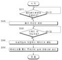
이하, 도 3을 참조하여 본 발명의 실시예에 따른 RKE 장치에 의한 스마트키 ECU 제어 방법에 대하여 설명한다. 도 3은 본 발명의 실시예에 따른 스마트키 ECU 제어 방법을 도시한 흐름도이다.Hereinafter, a smart key ECU control method by the RKE device according to the embodiment of the present invention will be described with reference to FIG. 3 is a flowchart illustrating a smart key ECU control method according to an embodiment of the present invention.
도 3을 참조하면, RKE 장치(20)는 접속부(221~224)가 연결부(121~124)에 접속됨에 따라 휴대폰(10)으로부터 전원이 공급되면(S310의 예), 동작하여 오실레이터(260)를 동작시켜 통신 주파수를 생성한다(S320).3, the RKE
RKE 장치(20)는 휴대폰의 마이컴(110)으로부터 스마트키 ECU에 대한 특정기능의 실행이 요청되면(S330의 예), 요청된 특정기능에 대응하는 제어신호를 생성한다(S340). 더 상세하게는, 사용자가 휴대폰(10)에 설치된 애플리케이션을 통해 특정기능을 요청하면, 마이컴(110)은 특정기능에 대응하는 데이터를 송신하고, RKE 장치(20)는 데이터의 내용을 파악하고 그 내용에 대응하는 제어신호를 생성한다.The
RKE 장치(20)는 제어신호를 통신 주파수에 실어 안테나(160)를 통해 스마트키 ECU로 송신한다(S350).The
그러면, 스마트키 ECU는 통신 주파수에 실린 제어신호를 복조하여 해석하고 제어신호에 대응하는 제어를 수행한다.Then, the smart key ECU demodulates and analyzes the control signal carried on the communication frequency, and performs control corresponding to the control signal.
이와 같이, 본 발명은 휴대폰에 애플리케이션을 설치하고, 애플리케이션을 통해 RKE 장치로 스마트키 ECU의 특정기능의 실행을 요청하여 스마트키 ECU를 제어함에 따라 스마트키 ECU의 소스가 휴대폰에 노출되는 것을 방지할 수 있으며, 애플리케이션을 설치하면 다양한 휴대폰에 적용될 수 있다.As described above, according to the present invention, an application is installed in a mobile phone, and an application requests the RKE device to execute a specific function of the smart key ECU to control the smart key ECU, thereby preventing the source of the smart key ECU from being exposed to the mobile phone And can be applied to various mobile phones by installing the application.
또한, 본 발명은 휴대폰의 인터페이스 및 안테나를 사용하되, RKE 장치(20)에 의해 휴대폰 안테나를 스마트키 ECU의 통신 주파수에 매칭시켜, 종래의 스마트키 ECU의 통신 주파수를 이용하므로, 차량의 스마트키 ECU를 별도로 변경시킬 필요가 없으며, 종래의 휴대폰을 이용하는 RKE처럼 통신비용에 대한 부담이 없다.Further, the present invention uses the interface of the mobile phone and the antenna, and uses the communication frequency of the conventional smart key ECU by matching the cellular phone antenna with the communication frequency of the smart key ECU by the
이상, 본 발명의 구성에 대하여 첨부 도면을 참조하여 상세히 설명하였으나, 이는 예시에 불과한 것으로서, 본 발명이 속하는 기술분야에 통상의 지식을 가진자라면 본 발명의 기술적 사상의 범위 내에서 다양한 변형과 변경이 가능함은 물론이다. 따라서 본 발명의 보호 범위는 전술한 실시예에 국한되어서는 아니되며 이하의 특허청구범위의 기재에 의하여 정해져야 할 것이다.While the present invention has been described in detail with reference to the accompanying drawings, it is to be understood that the invention is not limited to the above-described embodiments. Those skilled in the art will appreciate that various modifications, Of course, this is possible. Accordingly, the scope of protection of the present invention should not be limited to the above-described embodiments, but should be determined by the description of the following claims.
Claims (7)
Translated fromKorean상기 휴대폰의 마이컴으로부터 복수의 차량 스마트키 기능 중, 사용자가 상기 애플리케이션을 통해 요청한 적어도 하나의 기능의 실행을 요청받으면, 상기 적어도 하나의 기능에 대응하는 제어신호를 출력하는 RKE 마이컴;
상기 차량에 구비된 스마트키 ECU의 통신 주파수를 생성하는 오실레이터(Oscillator);
상기 휴대폰의 안테나를 상기 통신 주파수에 매칭하는 제1 매칭회로; 및
상기 제어신호를 상기 통신 주파수에 실어, 접속된 상기 휴대폰의 안테나를 통해 상기 스마트키 ECU로 송신하는 RF 통신부를 포함하고,
상기 연결부는, 상기 접속부가 접속되지 않으면, 상기 휴대폰의 이동통신 주파수에 상기 휴대폰의 안테나를 매칭하는 제2 매칭회로와 상기 안테나를 연결하여 이동통신 서비스가 제공되도록 하고, 상기 접속부가 접속되면, 상기 제2 매칭회로와 상기 휴대폰의 안테나 간의 연결을 개방하여, 상기 휴대폰의 안테나가 상기 제1 매칭회로와 연결되도록 하여, 상기 스마트키 ECU의 통신 주파수에 매칭되도록 하는 것인 RKE 장치.A connection unit connected to a microcomputer, an antenna, a mobile phone power supply, and a ground of the mobile phone when the mobile phone is installed in a connection portion of a mobile phone having an application for an RKE (Remote Keyless Entry) service;
An RKE microcomputer for outputting a control signal corresponding to the at least one function when a plurality of vehicle smart key functions requested by the user from the microcomputer of the cellular phone are requested to execute at least one function requested by the user through the application;
An oscillator for generating a communication frequency of the smart key ECU provided in the vehicle;
A first matching circuit for matching an antenna of the cellular phone to the communication frequency; And
And an RF communication unit for transmitting the control signal to the smart key ECU via the antenna of the mobile phone connected to the communication frequency,
Wherein the connection unit is provided with a mobile communication service by connecting the antenna with a second matching circuit that matches an antenna of the mobile phone with a mobile communication frequency of the mobile phone when the connection unit is not connected, Wherein the connection between the second matching circuit and the antenna of the cellular phone is opened so that the antenna of the cellular phone is connected to the first matching circuit to match the communication frequency of the smart key ECU.
상기 접속부가 상기 연결부에 장착되거나, 상기 애플리케이션이 실행되면, 상기 휴대폰의 이동통신 주파수에 상기 안테나를 매칭하는 제2 매칭회로와 상기 안테나 간의 연결을 개방하는 것인 RKE 장치.The cellular phone according to claim 1,
And the connection between the antenna and the second matching circuit matching the antenna to the mobile communication frequency of the cellular phone is opened when the connection part is mounted on the connection part or when the application is executed.
상기 휴대폰 전원이 상기 RKE 마이컴 및 상기 RF 통신부의 구동 전원과 상이할 때, 상기 휴대폰 전원을 상기 구동 전원으로 크기 변환하는 레귤레이터
를 더 포함하는 RKE 장치.The method according to claim 1,
A regulator for converting the power of the mobile phone into the driving power when the power of the mobile phone is different from the driving power of the RKE microcomputer and the RF communication unit
The RKE device further comprising:
RKE 서비스용 애플리케이션, 마이컴 및 안테나를 포함하는 휴대폰으로부터 전원이 공급되면, 상기 오실레이터에 의해 상기 스마트키 ECU의 통신 주파수를 생성하는 단계;
상기 휴대폰의 마이컴으로부터 복수의 차량 스마트키 기능 중, 사용자가 상기 애플리케이션을 통해 요청한 적어도 하나의 기능의 실행을 요청받으면, 상기 적어도 하나의 기능에 대응하는 제어신호를 출력하는 단계; 및
상기 제어신호를 상기 통신 주파수에 실어 상기 제1 매칭회로에 의해 상기 통신 주파수에 매칭된 상기 휴대폰의 안테나를 통해 상기 스마트키 ECU로 송신하는 단계를 포함하고,
상기 전원이 공급되면, 상기 휴대폰의 마이컴에 상기 휴대폰에 상기 RKE 장치가 장착됨을 보고하는 단계를 더 포함하고,
상기 휴대폰의 마이컴은, 상기 휴대폰에 상기 RKE 장치가 장착됨을 보고받으면, 상기 휴대폰의 이동통신 주파수에 상기 휴대폰의 안테나를 매칭하는 제2 매칭회로와 상기 휴대폰의 안테나 간의 연결을 개방하여, 상기 휴대폰의 안테나가 상기 스마트키 ECU의 통신 주파수에 매칭되도록 상기 제1 매칭회로와 연결되도록 하는 것인 스마트키 ECU 제어 방법.A smart key ECU control method of an RKE (Remote Keyless Entry) device including an oscillator and a first matching circuit,
Generating a communication frequency of the smart key ECU by the oscillator when power is supplied from a mobile phone including an RKE service application, a micom and an antenna;
Outputting a control signal corresponding to the at least one function when the user is requested to execute at least one function requested by the user through the application among the plurality of vehicle smart key functions from the microcomputer of the cellular phone; And
And transmitting the control signal to the smart key ECU via the antenna of the cellular phone matched to the communication frequency by the first matching circuit on the communication frequency,
When the power is supplied, reporting to the microcomputer of the mobile phone that the RKE device is installed in the mobile phone,
The microcomputer of the mobile phone opens a connection between the second matching circuit for matching the antenna of the mobile phone with the mobile communication frequency of the mobile phone and the antenna of the mobile phone when the microcomputer of the mobile phone reports to the mobile phone that the RKE device is mounted, And the antenna is connected to the first matching circuit so as to match the communication frequency of the smart key ECU.
상기 휴대폰으로부터 상기 전원을 공급받는 단계; 및
상기 전원의 크기가 상기 RKE 장치의 구동 전원과 상이하면, 상기 휴대폰으로부터의 전원을 상기 구동 전원의 크기로 변환하는 단계
를 더 포함하는 스마트키 ECU 제어 방법.
6. The method of claim 5,
Receiving the power from the cellular phone; And
Converting the power from the cellular phone to the size of the driving power source when the size of the power source is different from the driving power source of the RKE device
Further comprising the steps of:
Priority Applications (1)
| Application Number | Priority Date | Filing Date | Title |
|---|---|---|---|
| KR1020110090117AKR101908132B1 (en) | 2011-09-06 | 2011-09-06 | Remote Keyless Entry Unit which is installed on Mobile phone and Method for Controlling Smart Key Electronic Controller Unit thereof |
Applications Claiming Priority (1)
| Application Number | Priority Date | Filing Date | Title |
|---|---|---|---|
| KR1020110090117AKR101908132B1 (en) | 2011-09-06 | 2011-09-06 | Remote Keyless Entry Unit which is installed on Mobile phone and Method for Controlling Smart Key Electronic Controller Unit thereof |
Publications (2)
| Publication Number | Publication Date |
|---|---|
| KR20130026754A KR20130026754A (en) | 2013-03-14 |
| KR101908132B1true KR101908132B1 (en) | 2018-12-18 |
Family
ID=48177919
Family Applications (1)
| Application Number | Title | Priority Date | Filing Date |
|---|---|---|---|
| KR1020110090117AActiveKR101908132B1 (en) | 2011-09-06 | 2011-09-06 | Remote Keyless Entry Unit which is installed on Mobile phone and Method for Controlling Smart Key Electronic Controller Unit thereof |
Country Status (1)
| Country | Link |
|---|---|
| KR (1) | KR101908132B1 (en) |
Cited By (1)
| Publication number | Priority date | Publication date | Assignee | Title |
|---|---|---|---|---|
| US12099082B2 (en) | 2021-07-02 | 2024-09-24 | Toyota Motor Engineering & Manufacturing North America, Inc. | Systems and methods for conducting vehicle oscillator testing |
Families Citing this family (1)
| Publication number | Priority date | Publication date | Assignee | Title |
|---|---|---|---|---|
| KR101653384B1 (en)* | 2014-12-17 | 2016-09-02 | 주식회사 유디테크 | Method and system for controlling smart-key for vehicles |
Citations (4)
| Publication number | Priority date | Publication date | Assignee | Title |
|---|---|---|---|---|
| KR200334287Y1 (en)* | 2003-08-25 | 2003-11-22 | 권대웅 | Identification Confirm System Interface By PCS And Cellular Phones |
| JP2005060949A (en) | 2003-08-08 | 2005-03-10 | Dainippon Printing Co Ltd | Car door unlocking system |
| KR100695856B1 (en) | 2004-11-15 | 2007-03-20 | 가부시키가이샤 덴소 | Portable communication devices |
| JP2011045231A (en) | 2009-07-24 | 2011-03-03 | Denso Corp | Vehicle door control system, on-vehicle door controller, portable terminal, program for on-vehicle door controller, program for portable terminal, charged state notification system, charged state monitoring apparatus, and program for charged state monitoring apparatus |
- 2011
- 2011-09-06KRKR1020110090117Apatent/KR101908132B1/enactiveActive
Patent Citations (4)
| Publication number | Priority date | Publication date | Assignee | Title |
|---|---|---|---|---|
| JP2005060949A (en) | 2003-08-08 | 2005-03-10 | Dainippon Printing Co Ltd | Car door unlocking system |
| KR200334287Y1 (en)* | 2003-08-25 | 2003-11-22 | 권대웅 | Identification Confirm System Interface By PCS And Cellular Phones |
| KR100695856B1 (en) | 2004-11-15 | 2007-03-20 | 가부시키가이샤 덴소 | Portable communication devices |
| JP2011045231A (en) | 2009-07-24 | 2011-03-03 | Denso Corp | Vehicle door control system, on-vehicle door controller, portable terminal, program for on-vehicle door controller, program for portable terminal, charged state notification system, charged state monitoring apparatus, and program for charged state monitoring apparatus |
Cited By (1)
| Publication number | Priority date | Publication date | Assignee | Title |
|---|---|---|---|---|
| US12099082B2 (en) | 2021-07-02 | 2024-09-24 | Toyota Motor Engineering & Manufacturing North America, Inc. | Systems and methods for conducting vehicle oscillator testing |
Also Published As
| Publication number | Publication date |
|---|---|
| KR20130026754A (en) | 2013-03-14 |
Similar Documents
| Publication | Publication Date | Title |
|---|---|---|
| CN102547002B (en) | Vehicle data service based on low-power FM transmission | |
| KR101177660B1 (en) | Vehicle management system through radio relay of vehicle remote controller | |
| US8692651B2 (en) | Range extending positive repeater | |
| CN104527567A (en) | Automobile intelligent key system and using method thereof on basis of bluetooth low energy (BLE) | |
| US20140114503A1 (en) | Remote Function Fob for a Vehicle Passive Entry Passive Start System and Method for Operating Same | |
| CN105473392A (en) | Method for preventing relay attack on vehicle smart key system | |
| WO2010065408A3 (en) | System and method for configuring a wireless control system of a vehicle using induction field communication | |
| CN104875716A (en) | Method for automatically controlling safety lock and smart terminal | |
| KR20120090148A (en) | Method and system for controlling a car using smart phone | |
| CN201508624U (en) | Car remote-control starting system being free from passive burglary prevention or starting by entering key | |
| CN201563151U (en) | A portable mobile terminal with smart car key function | |
| CN104648323A (en) | Intelligent automobile key device | |
| KR101653384B1 (en) | Method and system for controlling smart-key for vehicles | |
| KR101908132B1 (en) | Remote Keyless Entry Unit which is installed on Mobile phone and Method for Controlling Smart Key Electronic Controller Unit thereof | |
| US7683756B2 (en) | Wireless access system and method | |
| CN101916503B (en) | Remote control method of remote control method | |
| KR20120128959A (en) | System and method for controlling vehicle by using near field communication | |
| KR20140025204A (en) | Wireless communication system for vehicle and control method thereof | |
| US20120071099A1 (en) | Portable device | |
| KR101131526B1 (en) | Wake up integrated management system for vehicle | |
| CN111497719B (en) | Beacon module | |
| US10505586B2 (en) | NFC method and device enabling power save mode during NFC connected mode for communication with improved power harvesting | |
| CN203727337U (en) | Device for enabling vehicle owner to enter vehicle without using remote control unit | |
| KR101340534B1 (en) | Method to protect Relay-attack of Smartkey System | |
| KR20170122617A (en) | Adaptive OBD Device for Broadcasting One-Way Radio Signal |
Legal Events
| Date | Code | Title | Description |
|---|---|---|---|
| PA0109 | Patent application | Patent event code:PA01091R01D Comment text:Patent Application Patent event date:20110906 | |
| PG1501 | Laying open of application | ||
| A201 | Request for examination | ||
| PA0201 | Request for examination | Patent event code:PA02012R01D Patent event date:20160518 Comment text:Request for Examination of Application Patent event code:PA02011R01I Patent event date:20110906 Comment text:Patent Application | |
| E902 | Notification of reason for refusal | ||
| PE0902 | Notice of grounds for rejection | Comment text:Notification of reason for refusal Patent event date:20170918 Patent event code:PE09021S01D | |
| E902 | Notification of reason for refusal | ||
| PE0902 | Notice of grounds for rejection | Comment text:Notification of reason for refusal Patent event date:20180330 Patent event code:PE09021S01D | |
| E701 | Decision to grant or registration of patent right | ||
| PE0701 | Decision of registration | Patent event code:PE07011S01D Comment text:Decision to Grant Registration Patent event date:20180928 | |
| GRNT | Written decision to grant | ||
| PR0701 | Registration of establishment | Comment text:Registration of Establishment Patent event date:20181008 Patent event code:PR07011E01D | |
| PR1002 | Payment of registration fee | Payment date:20181010 End annual number:3 Start annual number:1 | |
| PG1601 | Publication of registration | ||
| PR1001 | Payment of annual fee | Payment date:20210916 Start annual number:4 End annual number:4 | |
| PR1001 | Payment of annual fee | Payment date:20220926 Start annual number:5 End annual number:5 | |
| PR1001 | Payment of annual fee | Payment date:20230925 Start annual number:6 End annual number:6 | |
| PR1001 | Payment of annual fee |