KR101908057B1 - System, device and method for providing user interface for a virtual reality environment - Google Patents
System, device and method for providing user interface for a virtual reality environmentDownload PDFInfo
- Publication number
- KR101908057B1 KR101908057B1KR1020177016128AKR20177016128AKR101908057B1KR 101908057 B1KR101908057 B1KR 101908057B1KR 1020177016128 AKR1020177016128 AKR 1020177016128AKR 20177016128 AKR20177016128 AKR 20177016128AKR 101908057 B1KR101908057 B1KR 101908057B1
- Authority
- KR
- South Korea
- Prior art keywords
- processor
- computing platform
- portable computing
- user
- image
- Prior art date
- Legal status (The legal status is an assumption and is not a legal conclusion. Google has not performed a legal analysis and makes no representation as to the accuracy of the status listed.)
- Expired - Fee Related
Links
Images


Classifications
- G—PHYSICS
- G06—COMPUTING OR CALCULATING; COUNTING
- G06T—IMAGE DATA PROCESSING OR GENERATION, IN GENERAL
- G06T15/00—3D [Three Dimensional] image rendering
- G06T15/005—General purpose rendering architectures
- G—PHYSICS
- G06—COMPUTING OR CALCULATING; COUNTING
- G06F—ELECTRIC DIGITAL DATA PROCESSING
- G06F3/00—Input arrangements for transferring data to be processed into a form capable of being handled by the computer; Output arrangements for transferring data from processing unit to output unit, e.g. interface arrangements
- G06F3/01—Input arrangements or combined input and output arrangements for interaction between user and computer
- G06F3/011—Arrangements for interaction with the human body, e.g. for user immersion in virtual reality
- G06F3/012—Head tracking input arrangements
- G—PHYSICS
- G06—COMPUTING OR CALCULATING; COUNTING
- G06F—ELECTRIC DIGITAL DATA PROCESSING
- G06F3/00—Input arrangements for transferring data to be processed into a form capable of being handled by the computer; Output arrangements for transferring data from processing unit to output unit, e.g. interface arrangements
- G06F3/01—Input arrangements or combined input and output arrangements for interaction between user and computer
- G06F3/017—Gesture based interaction, e.g. based on a set of recognized hand gestures
- G—PHYSICS
- G06—COMPUTING OR CALCULATING; COUNTING
- G06F—ELECTRIC DIGITAL DATA PROCESSING
- G06F3/00—Input arrangements for transferring data to be processed into a form capable of being handled by the computer; Output arrangements for transferring data from processing unit to output unit, e.g. interface arrangements
- G06F3/01—Input arrangements or combined input and output arrangements for interaction between user and computer
- G06F3/03—Arrangements for converting the position or the displacement of a member into a coded form
- G06F3/0304—Detection arrangements using opto-electronic means
- G—PHYSICS
- G06—COMPUTING OR CALCULATING; COUNTING
- G06T—IMAGE DATA PROCESSING OR GENERATION, IN GENERAL
- G06T11/00—2D [Two Dimensional] image generation
- G06T11/60—Editing figures and text; Combining figures or text
- G—PHYSICS
- G06—COMPUTING OR CALCULATING; COUNTING
- G06T—IMAGE DATA PROCESSING OR GENERATION, IN GENERAL
- G06T19/00—Manipulating 3D models or images for computer graphics
- G06T19/006—Mixed reality
- H—ELECTRICITY
- H04—ELECTRIC COMMUNICATION TECHNIQUE
- H04N—PICTORIAL COMMUNICATION, e.g. TELEVISION
- H04N23/00—Cameras or camera modules comprising electronic image sensors; Control thereof
- H04N23/20—Cameras or camera modules comprising electronic image sensors; Control thereof for generating image signals from infrared radiation only
- H—ELECTRICITY
- H04—ELECTRIC COMMUNICATION TECHNIQUE
- H04N—PICTORIAL COMMUNICATION, e.g. TELEVISION
- H04N23/00—Cameras or camera modules comprising electronic image sensors; Control thereof
- H04N23/56—Cameras or camera modules comprising electronic image sensors; Control thereof provided with illuminating means
- H—ELECTRICITY
- H04—ELECTRIC COMMUNICATION TECHNIQUE
- H04N—PICTORIAL COMMUNICATION, e.g. TELEVISION
- H04N5/00—Details of television systems
- H04N5/222—Studio circuitry; Studio devices; Studio equipment
- H04N5/2224—Studio circuitry; Studio devices; Studio equipment related to virtual studio applications
- H04N5/2226—Determination of depth image, e.g. for foreground/background separation
- H04N5/2256—
- H—ELECTRICITY
- H04—ELECTRIC COMMUNICATION TECHNIQUE
- H04N—PICTORIAL COMMUNICATION, e.g. TELEVISION
- H04N5/00—Details of television systems
- H04N5/30—Transforming light or analogous information into electric information
- H04N5/33—Transforming infrared radiation
Landscapes
- Engineering & Computer Science (AREA)
- Theoretical Computer Science (AREA)
- General Engineering & Computer Science (AREA)
- Physics & Mathematics (AREA)
- General Physics & Mathematics (AREA)
- Human Computer Interaction (AREA)
- Multimedia (AREA)
- Signal Processing (AREA)
- Computer Graphics (AREA)
- Computer Hardware Design (AREA)
- Software Systems (AREA)
- Computer Vision & Pattern Recognition (AREA)
- User Interface Of Digital Computer (AREA)
- Processing Or Creating Images (AREA)
- Testing, Inspecting, Measuring Of Stereoscopic Televisions And Televisions (AREA)
- Controls And Circuits For Display Device (AREA)
- Position Input By Displaying (AREA)
- Length Measuring Devices By Optical Means (AREA)
Abstract
Translated fromKoreanDescription
Translated fromKorean본 발명은 일반적으로 가상 현실(virtual reality, VR) 환경에 관한 것이며, 특히 신체 제스처 및/또는 자세를 사용하여 VR 환경과의 자연스러운 인터페이싱을 가능하게 하는 장치 및 방법에 관한 것이다.The present invention relates generally to virtual reality (VR) environments, and more particularly to an apparatus and method for enabling natural interfacing with a VR environment using body gestures and / or postures.
본 발명의 배경이 제시되기에 앞서, 이하에서 사용될 특정 용어의 정의를 규정하는 것이 도움이 될 것이다.Before the context of the present invention is presented, it will be helpful to define the definition of the specific term to be used below.
본 명세서에서 사용되는 용어 '가상 현실'(VR)은 실제 세계 또는 상상의 세계에 대한 물리적 존재를 시뮬레이션할 수 있는 컴퓨터 시뮬레이션 환경으로 정의된다. 가상 현실은 가상의 맛, 시야, 냄새, 소리, 촉각 등을 포함하는 감각적 경험을 재생성할 수 있다. 다수의 종래의 VR 시스템들은 3D 가상 환경을 제시하기 위한 근안(near eye) 디스플레이를 사용한다.As used herein, the term " virtual reality " (VR) is defined as a computer simulation environment capable of simulating the physical presence of a real world or imaginary world. Virtual reality can regenerate sensory experience including virtual taste, sight, smell, sound, tactile sense, Many conventional VR systems use a near-eye display to present a 3D virtual environment.
본 명세서에서 사용되는 용어 '증강 현실(augmented reality, AR)'은 요소가 컴퓨터-생성된 감각 입력, 가령 소리, 비디오, 그래픽 또는 GPS 데이터에 의해 증강 (또는 보완)되는 물리적인, 현실 세계의 환경의 실시간의 직접 또는 간접적인 뷰로 정의된다. 이는, 현실의 뷰가 컴퓨터에 의해 수정되고 (가능하다면 심지어는 증강되는 것이 아닌 감소되는) 중재된 현실이라 지칭되는 더 일반적인 컨셉과 관련된다.As used herein, the term " augmented reality (AR) " refers to a physical, real-world environment in which elements are augmented (or supplemented) by computer-generated sensory input such as sound, video, Real-time < / RTI > This is related to the more general concept referred to as mediated reality in which the view of reality is modified by the computer (and possibly reduced, rather than augmented).
본 명세서에 사용되는 용어 '근안 디스플레이'는 웨어러블 프로젝션 디스플레이를 포함하고, 보통은 각 눈에 3D 지각을 생성하기 위해 다소 상이한 시야가 제시된다는 점에서 입체적인 장치로 정의된다.As used herein, the term " near vision display " includes a wearable projection display, and is generally defined as a stereoscopic device in that a somewhat different view is presented to create a 3D perception in each eye.
종종 '고글(goggles)'이라고 지칭되는 용어 '가상 현실 헤드셋'은 컴퓨터 출력을 디스플레이하기 위한 랩-어라운드(wrap-around) 시각적 인터페이스이다. 일반적으로 컴퓨터 디스플레이 정보는 실제 세상 환경의 3차원적 표현으로 제시된다. 고글은 (아마도 스마트폰 형태의) 컴퓨터 디스플레이를 유지하기 위한 단순한 구조 외의 광학 장치를 포함하거나 포함하지 않을 수 있다.The term 'virtual reality headset', sometimes referred to as 'goggles', is a wrap-around visual interface for displaying computer output. Generally, computer display information is presented as a three-dimensional representation of the real world environment. The goggles may or may not include simple non-structural optics to maintain a computer display (perhaps in the form of a smartphone).
도 1은 장면의 합성 이미지(16)를 사용자(10)의 각 눈으로 프로젝션하는 헤드 장착 입체 디스플레이(12)(예컨대, Oculus Rift™)를 사용자(10)가 착용하는 종래 기술에 따른 전통적인 VR 시스템을 도시한다. 보통 VR에서, 각 눈은 사용자의 뇌에 3D 지각을 생성하기 위해 다소 상이한 각도에서 합성 이미지(16)를 수신한다(단순화의 목적을 위해, 입체적 쌍은 도시되지 않는다). 추가로, 헤드 장착 디스플레이(12)에는, 가령 시야 각도 또는 사용자의 시선 방향을 감지할 수 있는 가속도계 또는 자이로(미도시)와 같은 센서가 제공될 수 있다. 결과적으로, VR 시스템은 사용자의 새로운 헤드 방향에 맞추기 위해 이미지(16)를 조정할 수 있다. 이러한 조정이 실시간으로 수행됨에 따라 실제 세상에서 헤드의 움직임을 모방하는 가상 현실의 환영이 이루어질 수 있다.1 shows a conventional VR system according to the prior art in which a
전술한 바와 같이 사용자의 시점을 추적하는 것 외에도, VR 시스템은 입력 장치, 가령 조이스틱(14) (또는 마우스, 터치패드 또는 심지어는 키보드)을 통해 가상 세계와의 추가적인 상호작용을 제공한다. 이러한 입력 장치는 사용자(10)가 다양한 동작을 수행하게 할 수 있다. 예컨대, VR 장면에 걸쳐 이미지(16) 상에 표시되는 커서(18)는 조이스틱(14)을 통해 사용자(10)에 의해 제어될 수 있다. 자연스럽게, 이러한 종래의 입력 장치의 사용은 전체적인 VR 사용자 경험을 손상시킨다. 추가로, 커서(18)의 사용은 사용자 경험을 개인용 컴퓨터로부터 알려진 표준 컴퓨터-사용자 인터페이스로 제한한다.In addition to tracking the user's point of view as described above, the VR system provides additional interaction with the virtual world via an input device, such as a joystick 14 (or a mouse, touchpad, or even keyboard). Such an input device may allow the
본 발명의 일부 실시예에 따르면, 사용자는 본 발명의 실시예에 따른 장치가, 아마도 애드-온으로 장착될 수 있는 근안 디스플레이를 착용할 수 있다. 장치는 일루미네이터(예컨대, 레이저 송신기) 및 시야가 사용자의 임의의 주변환경을 포함하기에 충분히 넓은 캡처링 유닛(예컨대, 카메라)을 포함할 수 있다. 동작시 근안 디스플레이는 사용자의 양안으로 합성 장면을 프로젝션하도록 구성된다. 일루미네이터는 사용자의 주변 및/또는 사용자를 패턴화 광으로 조명할 수 있다. 패턴화 광의 반사는 장치를 캡처함으로써 캡처될 수 있고, 이후 실시간으로 변화되는 사물, 가령 사용자의 손의 위치 및 배향을 표시하는 3차원적 시각 표현을 생성하기 위해 예컨대, 근안 디스플레이의 일부인 스마트폰에 위치할 수 있는 컴퓨터 프로세서에 의해 분석될 수 있다.According to some embodiments of the present invention, a user may wear a near vision display in which the device according to an embodiment of the present invention may be equipped with an add-on. The apparatus may include an illuminator (e.g., a laser transmitter) and a capturing unit (e.g., a camera) that is wide enough for the field of view to include the user's arbitrary surroundings. In operation, the near-vision display is configured to project the composite scene in both sides of the user. The illuminator may illuminate the user ' s periphery and / or the user with patterned light. The reflection of the patterned light can be captured by capturing the device and then used to create a three-dimensional visual representation representing the position and orientation of the user's hand, And may be analyzed by a computer processor that may be located.
다른 실시예에서, 장치는 손이나 사용자에 의해 제어되는 다른 제스처링 사물의 이미지를 캡처하기 위한 전용 소프트웨어에 의해 구성될 수 있는 스마트폰의 카메라를 이용할 수 있다. 동시에, 스마트폰의 프로세서는 장치에 의해 캡처된 데이터에 기반하여 동일한 손이나 제스처링 사물의 깊이 맵을 계산하도록 구성된다. 프로세스는, 가상 이미지의 대응 위치로 불러올 수 있는 손의 3차원 이미지로 깊이 맵과 시각 이미지의 데이터를 병합하도록 더 구성된다. 이러한 방식으로, 사용자의 실제 손을 그들의 3차원 속성을 유지하면서 VR 장면 내로 불러오게 된다.In another embodiment, the device may utilize the camera of a smart phone, which may be configured by dedicated software for capturing images of the hand or other gesturing object controlled by the user. At the same time, the processor of the smartphone is configured to calculate a depth map of the same hand or gesturing object based on the data captured by the device. The process is further configured to merge the depth map with the data of the visual image as a three-dimensional image of the hand, which can be called into the corresponding position of the virtual image. In this way, the user's actual hand is brought into the VR scene while maintaining their three-dimensional properties.
이들, 본 발명의 실시예의 추가적 및/또는 다른 측면 및/또는 이점은 다음의 상세한 설명에 기재되어 있고; 상세한 설명으로부터 추론가능하고; 및/또는 본 발명의 실시예의 실시에 의해 학습가능하다.These and / or other aspects and / or advantages of embodiments of the invention are set forth in the following detailed description; Inferable from the detailed description; And / or by the practice of the embodiments of the present invention.
본 발명의 내용 중에 포함되어 있다.Are included in the scope of the present invention.
본 발명의 실시예의 더욱 나은 이해를 위해 및 어떻게 수행되어 효과를 내는지 보이기 위하여, 참조가 예시의 방식으로 유사한 숫자가 대응하는 요소 또는 섹션에 지정되는 첨부되는 도면에 설명된다.
첨부되는 도면에서:
도 1은 종래 기술에 따른 가상 현실 시스템 및 그 환경을 도시하는 도면이다.
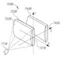
도 2는 본 발명의 일부 실시예에 따른 직접적인 환경에 부착되는 장치를 도시하는 사시도이다.
도 3은 본 발명의 일부 실시예에 따른 장치의 비-제한적인 구현을 도시하는 도면이다.
도 4는 본 발명의 일부 실시예에 따른 장치를 도시하는 블록도이다.
도 5a 및 도 5b는 본 발명의 실시예에 따른 일양태를 도시하는 도면들이다.
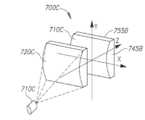
도 6은 본 발명의 일부 실시예에 따른 직접적인 환경에서 동작하는 장치를 도시하는 도면이다.
도 7a, 7b 및 7c는 본 발명의 실시예에 따른 가능한 패턴화 광 생성기의 블록도이다.
도 8은 본 발명의 실시예에 따른 패턴화 광의 일양태를 도시하는 도면이다.BRIEF DESCRIPTION OF THE DRAWINGS For a better understanding of the embodiments of the present invention and to show how the same may be carried out and effected, reference is set forth in the accompanying drawings in which like numerals are assigned to corresponding elements or sections in the manner of example.
In the accompanying drawings:
1 is a diagram showing a virtual reality system and its environment according to the prior art.
2 is a perspective view illustrating a device that is attached to a direct environment in accordance with some embodiments of the present invention.
3 is a diagram illustrating a non-limiting implementation of an apparatus in accordance with some embodiments of the present invention.
4 is a block diagram illustrating an apparatus in accordance with some embodiments of the present invention.
5A and 5B are views showing one embodiment according to an embodiment of the present invention.
6 is a diagram illustrating an apparatus operating in a direct environment in accordance with some embodiments of the present invention.
Figures 7A, 7B and 7C are block diagrams of a possible patterned light generator according to an embodiment of the present invention.
8 is a diagram showing one embodiment of patterned light according to an embodiment of the present invention.
이제 도면을 상세히 구체적으로 참조하면, 도시된 세부 사항은 단지 예일 뿐이고 본 기술의 바람직한 실시예에 대한 예시적인 논의만을 목적으로 함이 강조되고, 본 기술의 이론과 개념적인 측면의 가장 유용하고 이해 가능한 설명일 것으로 생각되는 것을 제공하기 위해 제시된다. 이에 관해, 본 기술의 구조적 세부사항을 더 자세히 보이려는 시도는 본 기술의 기본적 이해를 위하여 필요하지 않고, 도면과 함께 기재된 설명은 본 발명의 여러 형태가 어떻게 실제로 구현될 수 있는지 당업자에게 명백하다.Referring now to the drawings in detail, it is emphasized that the details shown are by way of example only and are for purposes of example discussion of preferred embodiments of the technology only, and that the most useful and understandable Desc / Clms Page number 2 > In this regard, an attempt to further elaborate the structural details of the present technique is not necessary for a basic understanding of the present technology, and the description with reference to the drawings is obvious to a person skilled in the art how various aspects of the present invention can be implemented in practice.
본 기술의 적어도 하나의 실시예를 상세히 설명하기 전에, 본 발명은 본 출원의 다음 설명 또는 도면에 도시된 구성요소의 구조 및 배열의 세부사항으로 제한되지 않음이 이해될 것이다. 본 기술은 다른 실시예에 적용가능하거나 다양한 방법으로 실시 또는 수행될 수 있다. 또한, 본 명세서에 사용된 어구 또는 용어는 설명을 위한 것이며 제한으로 간주되어서는 안된다.Before describing at least one embodiment of the technology in detail, it is to be understood that the invention is not limited to the details of construction and arrangement of components shown in the following description or drawings of the present application. The present technology may be applied to other embodiments or may be performed or performed in various ways. Also, the phrase or terminology employed herein is for the purpose of description and should not be regarded as limiting.
도 2는 팩킹되고 그것의 직접적인 환경(200)에 부착된 본 발명의 일부 실시예에 따른 모바일 장치, 가령 스마트폰(220)과 함께 사용하기 위해 구성되는 가상 현실(VR) 헤드셋(240)(고글)인 장치(210)의 사시도이다. 장치(210)는 일루미네이터(예컨대, 레이저 송신기), 가령 IR(infra-red) 패턴 일루미네이터(212)와 카메라, 가령 IR 카메라(214)를 포함할 수 있다. 장치(210)는 초기 이미지 프로세싱을 수행하도록 구성되는 사전-프로세서(미도시)를 더 포함할 수 있다. 장치(210)는 VR 헤드셋을 함께 형성하는 스마트폰(220) 및 근안 디스플레이(240) 둘 모두와 물리적 및 전기적으로 인터페이싱하도록 더 구성된다. 이러한 VR 헤드셋(고글)은 해당 업계에서 알려진 바와 같이 스마트폰과 함께 사용하도록 배치될 수 있고, 보통 스마트폰의 디스플레이(미도시 - 대향면을 향함)를 송신할 수 있는 광학계, 카메라(222)를 포함할 수 있는 스마트폰(220)을 수용하기 위한 슬리브(sleeve, 250), 및 VR 헤드셋(고글)을 사용자의 헤드로 고정하기 위한 스트랩(230)을 포함한다. 하지만, 장치(210)는 근안 디스플레이, 가령 Samsung Gear VR™ 및 Oculus Rift™와 인터페이싱할 수 있음이 이해된다.2 illustrates a virtual reality (VR)
동작시 장치(210)는 사용자의 손이나 다른 신체 부분의 3D 이미지를 VR 장면 내에서 볼 수 있도록 하는 능력을 추가함으로써 VR 헤드셋을 강화하기 위한 수단으로 기능할 수 있다. 이는 근안 디스플레이에 부착되는데 필요한 하드웨어 및 장치를 제어하고 그것에 의해 캡처되는 데이터를 분석하기 위해 VR 장치 프로세서 상에서 실행되는데 필요한 소프트웨어를 제공하는 장치(210)에 의해 수행된다. 경제적으로, 본 발명의 일부 실시예는 VR에 고유한 장치에 대한 필요를 제거하고 추가적으로 비용을 절감할 것이다.In operation, the
유익하게, 장치(210)는 최소 하드웨어, 가령 패턴화 광 일루미네이터 및 패턴의 반사를 캡처하기 위한 카메라만을 제공한다. 스마트폰(220)에 연결하는 인터페이스는 필요한 전력을 공급하고, 스마트폰(220)으로 획득된 데이터를 전달할 수 있고, 여기서 모든 프로세싱이 수행되어서 그것의 컴퓨팅 전력을 이용하게 된다. 따라서, 본 발명의 일부 실시예에 따르면 VR 시스템의 설치는 매우 쉬워지고 스마트폰이나 고글과 같은 기성(off-the-shelf) 컴포넌트를 이용하게 된다.Advantageously, the
도 3은 본 발명의 일부 실시예에 따른 비-제한적 예시적인 구현의 기계적 다이어그램이다. 사시도는 컴포넌트들이 설치되고 베이스 유닛(305)에 물리적으로 부착될 수 있는 프린트된 회로 보드(printed circuit board, PCB)(301)를 도시한다. 예시적인 구현의 주요 컴포넌트는 충분한 전력과 아마도 변조를 레이저 송신기(360)에 공급하도록 구성된 레이저 드라이버(320)에 결합된 레이저 송신기(360)이다. 아마도 VGA 카메라인 카메라(330)는 패턴화 광의 반사를 수신하도록 구성된다. 일실시예에 따르면, PCB는 카메라(330)를 덮는 IR 필터(350)를 포함할 수 있다. 일부 실시예로, 카메라(330)에 의해 수신되는 패턴화 광 반사와 관련된 데이터와 같은 데이터는 초기에 예컨대, 신호 프로세서(310)에 의해 프로세싱되고 이후 포트, 가령 USB 포트(340)를 통해 제3자 프로세서(미도시)로 전달되며, 예컨대, 데이터는 스마트폰의 USB 포트로 USB 프로토콜 상에서 전달될 수 있고 스마트폰의 프로세서 상에서 실행되는 애플리케이션과 상호작용할 수 있다. 장치를 위한 전력은 또한, USB 포트(340)를 통해 제공될 수 있다. 가령 초기 이미지 프로세서(TIP)와 같은 다양한 집적 회로(IC)뿐만 아니라 추가 카메라를 위한 소켓이 또한, PCB에 부착되고 여기에 도시된다.Figure 3 is a mechanical diagram of a non-limiting exemplary implementation in accordance with some embodiments of the present invention. The perspective view shows a printed circuit board (PCB) 301 in which components are installed and can be physically attached to the
일부 실시예로, 카메라(330)는 장치로부터 생략될 수 있고 외부 휴대용 컴퓨팅 플랫폼(스마트폰)의 카메라가 대신 사용될 수 있다. 발명자는 장치의 몇몇 원형을 테스트하였고, 카메라(330)를 갖는 장치에 대해 1와트의 저전력 소비가 측정되는 한편, 카메라(330)가 없는 경우 심지어 550 밀리와트의 저전력 소비가 측정되었다.In some embodiments,
도 4는 본 발명의 일부 실시예에 따른 전술한 장치 및 그 직접적인 환경의 구조를 도시하는 블록도이다. 장치(400)는 패턴화 광으로 장면을 조명하도록 구성된 IR 일루미네이터; 패턴화 광의 반사를 수신하도록 구성된 IR 카메라(406) 및 IR 카메라(406)로부터의 데이터의 초기 프로세싱을 수행하도록 구성된 사전-프로세서를 포함할 수 있다. 장치(400)는 프로세서(414) 및 프로세서(414)에 의해 실행되는 장치(400)와 연관된 소프트웨어 모듈을 포함할 수 있는 휴대용 컴퓨팅 플랫폼, 가령 스마트폰(410)과 인터페이싱하도록 더 구성된다. 스마트폰(410)은 사용자에게 합성 장면 및 추가적으로 사용자의 신체 부분(예컨대, 손)의 3D 이미지를 제시하도록 구성된 근안 디스플레이(420)에 더 연결된다. 플랫폼은 또한, 랩톱 개인용 컴퓨터 (PC), 태블릿 PC 등일 수 있음을 유의해야 한다.4 is a block diagram illustrating the structure of the aforementioned apparatus and its immediate environment in accordance with some embodiments of the present invention.
동작 시에 일루미네이터(402)에 의해 조명되는 반사된 IR 패턴은 IR 카메라(406)에 의해 캡처되고 사전-프로세서(404)에 의한 일부 초기 프로세싱 후에 데이터는 전용 소프트웨어(416)와 함께 스마트폰(410)의 프로세서(414)로 전달되며, 프로세서(414)는 반사된 패턴에 기반하여 사용자의 신체 부분의 깊이 맵을 생성한다. 가시광 카메라(412)는 패턴화 광으로 조명되었던 사용자의 동일한 신체 부분(예컨대, 손)의 2D 컬러 이미지를 캡처하도록 구성될 수 있다. 따라서, 프로세서(414)는 캡처된 신체 부분의 3D 컬러 이미지를 생성하기 위해 신체 부분의 깊이 맵과 2D 컬러 이미지 둘 모두를 사용할 수 있다. 마지막으로, 프로세서(414)는 합성 VR 장면 상에 캡처된 신체 부분의 생성된 3D 컬러 이미지를 중첩(superimpose)하여 사용자가, 실제 삶에서 존재하는 바와 같이 배치되고 배향되는, 3D 컬러 이미지로서 VR 장면 및 그의 또는 그녀의 캡처된 신체 부분(예컨대, 손) 둘 모두를 근안 디스플레이(420)를 통해 볼 수 있게 하도록 구성된다.The reflected IR pattern illuminated by the
도 5a 및 도 5b는 본 발명의 일부 실시예에 따른 일양태를 도시하는 도면들이다. 사용자(500)는 본 발명의 일부 실시예에 따라 장치(510)를 착용하는 것으로 보여진다. 여기에서 단순화의 목적을 위해 수반되는 헤드셋 없이 오로지 장치만이 도시됨을 유의해야 한다. 도 5a는 장치(510)의 일루미네이터 및 IR 카메라 둘 모두의 시야를 도시한다. 패턴화 광(530A)에 의해 커버되는 영역은 세로(portrait) 구성으로 도시되는 IR 카메라(520A)에 의해 커버되는 영역을 실질적으로 오버랩한다. 도 5b는, IR 카메라가 90° 회전되고 일루미네이터가 또한, 차라리 회전되거나 대안으로 표면을 생성하는 그것의 패턴은 본질적으로 세로가 되도록 펼쳐지는 가로(landscape) 구성으로 유사하게 오버랩하는 시야를 도시한다. 가로 배향의 사용은 손의 전체 스팬(span)이 자연스러운 자세와 제스처가 수행되고 모니터되는 것을 가능하게 하기 위해 중요한 VR 애플리케이션에 유리하다. 실험 동안에 발명자들은 약 43°의 수평 시야 및 약 55°의 수직 시야가 세로 구성에서 본 발명의 실시예에 대한 양호한 결과를 양산해냄을 발견하였다. 유사하게, 약 55°의 수평 시야 및 약 43°의 수평 시야가 가로 구성에 대해 양호한 결과를 양산한다. 다른 시야가 본 발명의 다른 실시예에 따라 다른 장치들로 사용될 수 있음이 이해된다.Figures 5A and 5B are views showing one embodiment according to some embodiments of the present invention. The
도 6은 본 발명의 실시예에 따른 장치 및 그것의 통상적인 환경을 도시하는 개략도이다. 사용자(10)는 장치(600)가 위에서 설명된 애드온으로서 아마도 장착될 수 있는 근안 디스플레이(630)를 착용한다. 장치(600)는 전술한 바와 같이 사용자의 임의의 주변환경을 포함하기에 충분히 넓은 시야를 갖는 캡처 유닛(610)(예컨대, 카메라) 및 일루미네이터(620)(예컨대, 레이저 송신기)를 포함할 수 있다.6 is a schematic diagram showing a device and its typical environment according to an embodiment of the present invention. The
동작시 근안 디스플레이(630)는 사용자(10)의 양 눈에 합성 장면을 프로젝션하도록 구성된다. 일루미네이터(610)는 사용자(10) 부근을 패턴화 광(624)으로 조명할 수 있다. 패턴화 광의 반사는 캡처링 장치(610)에 의해 캡처될 수 있고, 이후 예컨대, 근안 디스플레이(630)에 장착된 스마트폰 상에 위치할 수 있는 컴퓨터 프로세서(여기에서는 미도시)에 의해 분석될 수 있다. 스마트폰 (또는 대안으로 장치(600)의 일부)의 가시광 카메라는 사용자의 손 또는 사용자(10)에 의해 제어되는 다른 제스처링 사물의 2D 이미지를 캡처하도록 구성된다. 동시에 스마트폰의 프로세서는 손이나 제스처 사물의 깊이 맵을 계산하고, 가상 이미지(660)에서 대응하는 위치로 불러올 수 있는 손(662)의 3D 이미지로 깊이 맵과 시각 이미지의 데이터를 병합하도록 구성된다. 이러한 방식으로 사용자(10)의 손의 3D 이미지는 그들의 3D 속성을 유지하면서 VR 장면 상에 중첩된다.In operation, the
도 7a 내지 7c는 다중-라인 패턴 생성기의 형태로 일루미네이터(패턴화 광의 광원)를 구현하는 다양한 실시예를 도시하는 도면이다. 이와 같이, 그것은 레이저 소스 및 레이저 빔을 복수의 라인으로 변환하는 광학계를 포함한다. 어떻게 구조화 광이 구현될 수 있는지에 대한 추가 세부사항을 제공하기 위해, 오로지 예시적으로, 이하의 출원의 전체가 본 명세서에 참조로 통합된다: 미국 특허출원 제13/497,586호, WIPO 특허출원 공보 WO 2013088442 및 미국 임시특허출원 제61/863,510호, 제61/894,471호 및 제61/926,476호.7A-7C are diagrams illustrating various embodiments for implementing an illuminator (a light source of patterned light) in the form of a multi-line pattern generator. As such, it includes a laser source and an optical system that converts the laser beam into a plurality of lines. To provide further details as to how structured light can be implemented, by way of example only, the entirety of the following applications are incorporated herein by reference: U.S. Patent Application No. 13 / 497,586, WIPO Patent Application Publication WO 2013088442 and U.S. Provisional Patent Applications 61 / 863,510, 61 / 894,471 and 61 / 926,476.
도 7a는 본 발명의 제1 실시예에 따른 패턴 생성 시스템(700A)의 구성을 도시한다. 시스템(700A)은 광원, 가령 레이저 다이오드 광원(710A) 및 단일 광학 렌즈 요소(120)를 포함할 수 있다. 광학 요소(720A)는 다음의 3가지 기능(구체적으로는 이러한 순서는 아님)을 제공하고, 따라서 가령 공간이나 표면 또는 사물 상에서 패턴을 생성할 수 있다: a) 라인 생성, b) 증폭(multiplication), c) 시준(collimation).FIG. 7A shows a configuration of a
본 발명의 제1 실시예에 따르면, 적어도 2개의 표면, 제1 광학 표면(725A) 및 제2 광학 표면(735A)을 포함하는 단일 렌즈 광학 요소(720A)가 제공된다. 제1 단면, 가령 제1 광학 표면의 Y-Z 단면에서, 렌즈 요소(120)는 양의 광 출력을 가진다. 이러한 양의 광 출력은 느린 발산 섹션에서 레이저 광을 시준하는데 사용된다.According to a first embodiment of the present invention, there is provided a single lens
제2 단면, 가령 렌즈의 제2 표면(735A) 또는 제1 표면(725A)의 X-Z 단면에서 요소(720A)는 라인 생성기를 가진다. 라인 생성기는 양의 광 출력, 가령 비구면 렌즈, 원통형 렌즈 또는 회절 요소 또는 음의 광학 표면 또는 조합된 음/양의 표면 등의 형태일 수 있다. 단일 광학 요소(700A)는 제1 단면, 가령 제2 표면(735A)의 Y-Z 단면에 형성된 빔 분할 요소를 더 포함한다.
도 7b는 본 발명의 제2 실시예에 따른 패턴 생성 시스템(700B)의 구성을 도시한다. 시스템(700B)은 광원, 가령 레이저 다이오드 광원(710B) 및 2개의 광학 렌즈 요소, 제1 렌즈 요소(720B) 및 제2 렌즈 요소(740B)를 포함할 수 있다. 적어도 하나의 단면(예컨대, 빠르거나 느린 축), 가령 제1 렌즈의 제1 표면(725B)의 Y-Z 단면에서, 요소(720B)는 양의 광 출력을 가지고, 제1 광학 요소의 다른 단면(즉, X-Z 단면)에서 증폭 기능이 레이저 소스(710B)에 의해 제공되는 빔을 분할하기 위해 제2 표면(727B)에서 제공된다.FIG. 7B shows a configuration of a
제1 렌즈 요소(720B)에 인접하거나 그 근방에서 제2 렌즈 요소(740B)가 제공되고 라인 패턴과 같은 패턴을 생성하도록 구성된다. 라인 패턴은 예컨대, 제1 표면(745B)의 Y-Z 단면에서 제2 요소(740B)의 제1 표면(745B)의 제1 단면에 제공될 수 있다.A second lens element 740B is provided adjacent to or near the
도 7c는 본 발명의 제3 실시예에 따른 패턴 생성 시스템(700C)의 구성을 도시한다. 시스템(700C)은 광원, 가령 레이저 다이오드 광원(710C) 및 2개의 광학 렌즈 요소, 제1 렌즈 요소(720C) 및 제2 렌즈 요소(730C)를 포함할 수 있다. 적어도 하나의 단면, 가령 제1 렌즈의 제1 표면(755C)의 Y-Z 단면에서 요소(745C)는 양의 광 출력을 가진다.Fig. 7C shows a configuration of a pattern generating system 700C according to the third embodiment of the present invention. System 700C may include a light source, such as a laser diode light source 710C and two optical lens elements, a
제1 렌즈 요소(720C)에 인접하여 또는 그 근방에 2개의 기능을 생성하기 위해 제2 렌즈 요소(740C)가 제공된다: 1) 라인 생성, 및 2) 증폭. 예컨대, 패턴, 가령 라인 패턴이 제1 표면의 제1 단면(즉, Y-Z 단면)에 형성되고 증폭 기능은 제2 표면(755C)의 다른 단면(즉, X-Z 단면)에 형성된다.A second lens element 740C is provided to create two functions adjacent to or near the
본 발명의 일부 실시예에 따르면, 제1 및 제2 요소는 해당 기술분야에 알려진 용접이나 접착 기술에 의해 서로와 결합될 수 있다.According to some embodiments of the present invention, the first and second elements may be coupled to each other by welding or bonding techniques known in the art.
본 발명의 다른 실시예에 따르면, 제2 렌즈 요소의 회절 표면은, 민감성 회절 표면을 보호하고 회절 표면과의 원하지 않는 외부 요소의 임의의 접촉을 방지하기 위해 제1 렌즈 요소의 표면을 마주본다.According to another embodiment of the invention, the diffractive surface of the second lens element faces the surface of the first lens element to protect the sensitive diffractive surface and prevent any contact of undesired external elements with the diffractive surface.
본 발명의 일부 실시예에 따르면, 라인 생성 기능은 양의 광 표면, 조합된 음/양의 표면 또는 회절 표면을 사용하여 형성될 수 있다.According to some embodiments of the present invention, the line generating function may be formed using a positive optical surface, a combined negative / positive surface, or a diffractive surface.
예시적인 실시예에 따르면, 손의 움직임의 추적은, 손의 움직임, 가령 손가락 과 엄지의 미세한 움직임의 감지를 가능하게 하도록 구성된 광 패턴을 사용하여 수행된다. 구조화 광의 사용은, 예컨대, 전체가 본 명세서에 참조로 통합되는 국제공개공보 WO 2013/088442에 개시되는 바와 같을 수 있다.According to an exemplary embodiment, tracking of the movement of the hand is performed using a light pattern configured to enable sensing of movement of the hand, e.g., the fine movement of the finger and the thumb. The use of structured light may be, for example, as disclosed in WO 2013/088442, the entire disclosure of which is incorporated herein by reference.
특별히 설계된 광 패턴은, 심지어는 3차원 깊이 맵과 다르게 손을 신체의 나머지로부터 쉽게 분리하는 것을 제공하지 않는 2차원 비디오 데이터에서 움직임의 추적을 허용한다.Specially designed light patterns allow tracking of motion in two-dimensional video data that does not even provide for easy separation of the hand from the rest of the body, unlike a 3D depth map.
선택적으로, 광 패턴은 2차원 비디오 데이터(예컨대, 일반 비디오 카메라로부터 스트리밍된 비디오 이미지)에서 손의 손가락의 움직임을 추적하도록 특별히 설계될 수 있다. 보다 구체적으로는, 광 패턴은 손가락에 의한 패턴의 변형에 따라 2차원 비디오 데이터에서 손바닥뿐만 아니라 손가락(즉, 손가락 및 엄지 손가락)의 감지 및 추적을 가능하게 하도록 설계될 수 있다.Alternatively, the light pattern may be specially designed to track the movement of a finger of a hand in two-dimensional video data (e.g., a video image streamed from a generic video camera). More specifically, the light pattern can be designed to enable detection and tracking of fingers (i.e., fingers and thumbs) as well as palms in two-dimensional video data according to a variation of the pattern by the fingers.
선택적으로, 광 패턴은 제1 방향(가령, X-축)에서 연속적 특성 및 제1 방향에 실질적으로 수직인 방향(가령, Y-축)에서 불연속적(가령, 주기적) 특징을 가진다. 이러한 패턴의 일례에서, 광 패턴은 서로에 대해 평행으로 (또는 평행에 가깝게) 정렬되는 몇몇 스트라이프(stripe)를 포함한다.Alternatively, the light pattern has discontinuous (e.g., periodic) features in a continuous direction in a first direction (e.g., the X-axis) and a direction (e.g., Y-axis) substantially perpendicular to the first direction. In one example of such a pattern, the light patterns include several stripes that are aligned parallel (or close to parallel) with respect to each other.
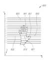
도 8은 본 발명의 실시예에 따른 패턴화 광의 일양태를 도시하는 도면이다.8 is a diagram showing one embodiment of patterned light according to an embodiment of the present invention.
다음은 사용자에 의해 만들어진 제스처를 추적하기 위해 어떻게 생성된 패턴화 광이 사용되는지에 관한 더 상세한 설명이다. 예시적인 실시예에 따르면, 센서(여기서 미도시)는 특정 Y-축 거리에, 예컨대, 손(810) 과 배경(820)(가령, 손이 얹혀있는 테이블의 표면, 벽 등) 상에 스트라이프 패턴을 프로젝션하는 송신기 근처에 배치될 수 있다. 센서의 위치는, 카메라, 광 프로젝터 및 사용자의 손(810)과 배경(820)으로부터 반사된 광 사이의 삼각측량(triangulation) 효과를 생성하도록 선택된다.The following is a more detailed description of how the generated patterned light is used to track gestures created by the user. According to an exemplary embodiment, a sensor (not shown) may be attached to a particular Y-axis distance, for example, a
삼각측량 효과는 광 패턴으로 프로젝션된 사물로부터 상당한 깊이의 편이가 있는, 스트립을 따르는 지점들에서 패턴의 불연속성을 발생시킨다. 불연속성은 스트립을 2개 이상의 스트립 세그먼트, 가령 손 위에 배치되는 세그먼트(831), 손의 좌측에 배치되는 세그먼트(832) 및 손의 우측에 배치되는 세그먼트(833)로 세그먼트화(즉, 분할)한다.The triangulation effect produces a discontinuity in the pattern at the points along the strip, with significant depth deviations from the object projected with the light pattern. The discontinuity segments (i.e., divides) the strip into two or more strip segments, such as a
이러한 깊이 편이가 생성된 스트립 세그먼트는 카메라와 사용자의 신체 사이에 배치된 사용자의 손의 손바닥이나 손가락의 윤곽에 위치할 수 있다. 즉, 사용자의 손가락이나 손바닥은 스트립을 2개 이상의 스트립 세그먼트로 세그먼트화한다. 이러한 스트립 세그먼트가 일단 감지되면, 스트립 세그먼트의 단부까지 스트립 세그먼트를 따라가기가 용이하다.The strip segment from which such depth deviation is generated may be located in the outline of the palm or fingers of the user's hand placed between the camera and the user's body. That is, the user's finger or palm segments the strip into two or more strip segments. Once such a strip segment is detected, it is easy to follow the strip segment to the end of the strip segment.
따라서, 장치는 스트립 세그먼트의 클러스터를 생성하기 위해 2차원 비디오 데이터를 분석할 수 있다. 예컨대, 장치는 손의 손가락에 의한 스트라이프의 세그먼트화에 의해 생성된 하나 이상의 스트립 세그먼트의 클러스터, 가령 손의 가운데 손가락으로부터 반사된 4개의 세그먼트의 클러스터(841)를 광 패턴에서 식별할 수 있다. 결국, 장치는 손가락에 의한 스트라이프의 세그먼트화에 의해 생성된 스트립 세그먼트의 클러스터를 추적하거나 클러스터의 세그먼트 중 적어도 하나를 추적함으로써 손가락의 움직임을 추적한다.Thus, the apparatus can analyze the 2D video data to create clusters of strip segments. For example, the device may identify in a light pattern a cluster of one or more strip segments generated by segmentation of a stripe by a finger of the hand, e.g., a cluster of four
손가락에 의한 스트라이프의 세그먼트화(즉, 분할)에 의해 생성된 스트립 세그먼트의 클러스터는 X 축에서 오버랩을 갖는 스트립 세그먼트를 포함한다. 선택적으로, 클러스터의 스트립 세그먼트는 또한, (손가락 두께로부터 도출된) 유사한 길이 또는 Y-축 좌표에서의 상대적 인접성을 가진다.Clusters of strip segments generated by segmentation (i.e., segmentation) of the stripes by the fingers include strip segments with overlaps in the X-axis. Optionally, the strip segment of the cluster also has a relative length (derived from finger thickness) or relative proximity in Y-axis coordinates.
X-축 상에서, 세그먼트는 직선으로 배치된 손가락에 대한 전체 오버랩, 또는 X-Y 평면에서 대각선으로 배치된 손가락에 대한 부분 오버랩을 가질 수 있다. 선택적으로, 장치는 가령 추적된 클러스터에서 세그먼트의 개수의 변화를 감지함으로써 손가락의 깊이 움직임을 더 식별한다. 예컨대, 사용자가 사용자의 가운데 손가락을 늘리면, 손가락과 광 프로젝터 및 카메라(X-Y 평면) 사이의 각도가 변한다. 결과적으로, 클러스터(814)의 세그먼트의 개수는 4에서 3으로 감소된다.On the X-axis, a segment may have a full overlap with a finger arranged in a straight line, or a partial overlap with a finger placed diagonally in the X-Y plane. Optionally, the device further identifies the depth motion of the finger, for example by sensing a change in the number of segments in the tracked cluster. For example, when the user increases the middle finger of the user, the angle between the finger and the light projector and the camera (X-Y plane) changes. As a result, the number of segments of cluster 814 is reduced from four to three.
선택적으로, 장치는 손의 손바닥에 의한 스트라이프의 세그먼트화에 의해 생성된 하나 이상의 스트립 세그먼트의 하나 이상의 클러스터를 광 패턴에서 더 식별한다.Optionally, the device further identifies in the light pattern one or more clusters of one or more strip segments generated by segmentation of the stripes by the palm of the hand.
손바닥에 의한 스트라이프의 세그먼트화에 의해 생성된 스트립 세그먼트의 클러스터는 X-축에서 사용자 손의 손가락 스트립 세그먼트 클러스터와 오버랩되는 상부 스트립 세그먼트(831)를 포함한다. 상부 스트립 세그먼트(831)는 X-축에서 4개의 손가락 클러스터와 오버랩하지만, 4개의 손가락 클러스터의 하부 세그먼트의 최소 및 최대 X 값을 초과하지 않는다.The cluster of strip segments generated by the segmentation of the stripe by the palm comprises an
손바닥에 의한 스트라이프의 세그먼트화에 의해 생성된 스트립 세그먼트의 클러스터는 세그먼트(831)의 바로 아래에 스트립 세그먼트(831)와 상당히 오버랩되는 몇몇 스트립 세그먼트를 더 포함한다. 손바닥에 의한 스트라이프의 세그먼트화에 의해 생성된 스트립 세그먼트의 클러스터는 사용자의 엄지손가락의 스트립 세그먼트 클러스터(851)의 베이스까지 연장되는 더 긴 스트립 세그먼트를 더 포함한다. 손가락 및 손바닥 클러스터의 배향은 특정한 손의 위치 및 회전에 따라 상이할 수 있음이 이해된다.The cluster of strip segments generated by the segmentation of the stripes by the palm further includes some strip segments that substantially overlap the
유익하게는, 장치의 전력 소비는, 전원이 스마트폰의 경우와 같이 제한되는 때라도 간섭되지 않고 연속적인 동작을 가능하게 할 만큼 충분히 감소된다. 전술한 바와 같이, 본 발명의 일부 실시예는 에너지 차단을 수반하는 종래 기술의 솔루션과는 대조적으로 에너지가 공간적으로 전환되는 간섭에 기반하는 패턴 생성을 이용한다. 간섭 기반 패턴 생성의 사용은 에너지적으로 더 효율적이다. 위에서 추가로 설명된 바와 같이, 깊이 맵의 생성은 계산 강도를 감소시키는 부분 패턴 프로세싱을 가능하게 하는 반사의 세그먼트에 기반한다. 이는 또한, 전체 전력 소비를 감소시키는데 기여한다. 일부 실시예로, 스마트폰의 자동 초점맞춤(autofocus) 기능이 패턴으로 프로젝션되는 사물의 범위와 관련되는 초기 데이터를 제공하기 위해 사용될 수 있다. 이는 또한, 저전력 소비에 기여한다. 위의 모든 저전력 소비 기능은 아마도 전력 소비의 관점에서 VR 헤드셋으로서 스마트폰 및 근안 디스플레이의 인터페이스를 생성하는데 상당히 기여한다.Advantageously, the power consumption of the device is reduced sufficiently to enable continuous operation without interference, even when the power source is limited, such as in the case of a smartphone. As described above, some embodiments of the present invention utilize pattern generation based on interference where energy is spatially switched in contrast to prior art solutions involving energy interception. The use of interference-based pattern generation is energetically more efficient. As described further above, the generation of a depth map is based on segments of reflections that enable partial pattern processing to reduce computational strength. This also contributes to reducing overall power consumption. In some embodiments, the autofocus function of the smartphone may be used to provide initial data related to the extent of an object being projected in a pattern. It also contributes to low power consumption. All of the above low power consumption features contribute significantly to creating interfaces for smart phones and near vision displays as VR headsets, perhaps in terms of power consumption.
상기 설명에서, 실시예는 본 발명의 예시 또는 구현이다. 다양한 형태의 "일실시예", "실시예" 또는 "일부 실시예"는 반드시 모두 동일한 실시예를 지칭하는 것이 아니다.In the above description, the embodiment is an example or implementation of the present invention. The "one embodiment "," embodiment ", or "some embodiments" of various forms do not necessarily all refer to the same embodiment.
본 발명의 다양한 특징이 단일 실시예의 문맥에서 서술될 수 있지만, 특징은 별개로 또는 임의의 적절한 조합에서 제공될 수 있다. 반대로, 본 명세서에서 본 발명이 명확성을 위해 별개의 실시예의 문맥에서 서술될 수 있지만, 본 발명은 단일 실시예에서도 구현될 수 있다.While various features of the invention may be described in the context of a single embodiment, the features may be provided separately or in any suitable combination. Conversely, although the present invention may be described herein in the context of separate embodiments for clarity, the present invention may be implemented in a single embodiment.
명세서에서 "일부 실시예", "한 실시예", "일실시예" 또는 "다른 실시예"의 지칭은 실시예와 관련하여 서술된 특정한 특징, 구조 또는 특성이 적어도 일부의 실시예에 포함되는 것이나, 반드시 본 발명의 모든 실시예에 포함되는 것은 아니라는 것을 의미하는 것이다.Reference in the specification to " some embodiments, "" one embodiment," " one embodiment, "or" another embodiment "means that a particular feature, structure, or characteristic described in connection with the embodiment is included in at least some embodiments But it is not necessarily included in all embodiments of the present invention.
본 명세서에서 사용된 어구 및 용어는 제한으로 해석되지 않고 설명의 목적만을 위한 것이라는 것이 이해될 것이다.It is to be understood that the phraseology and terminology employed herein is for the purpose of description and not of limitation.
본 발명의 개시의 원리 및 사용은 첨부된 설명, 도면 및 예시를 참조하여 더 잘 이해될 수 있다.The principles and use of the disclosure of the present invention may be better understood with reference to the accompanying description, drawings and examples.
본 명세서의 세부 사항은 본 발명의 응용을 제한으로 해석되지 않는다는 것이 이해될 것이다.It will be understood that the details of the disclosure are not to be construed as limiting the application of the invention.
나아가, 본 발명은 다양한 방식으로 수행 또는 실시될 수 있고 본 발명은 상기 설명에서 서술된 것과 다른 실시예로 구현될 수 있음이 이해될 것이다.Furthermore, it is to be understood that the invention may be practiced or carried out in various ways and that the invention may be practiced otherwise than as described in the foregoing description.
용어 "포함하는(including)", "포함(comprising)", "이루어진" 및 그 문법적 변형은 하나 이상의 구성요소, 특징, 단계 또는 정수나 그 그룹의 추가를 못하게 하지 않으며 용어들은 구성요소, 특징, 단계 또는 정수를 명시하는 것으로 해석되는 것이 이해될 것이다.The terms "including", "comprising", "consisting of" and grammatical variations thereof do not preclude the addition of one or more elements, features, steps, or integers or groups thereof, Steps or integers, unless the context clearly dictates otherwise.
명세서 또는 청구범위가 "추가적" 요소를 지칭한다면, 하나 이상의 추가적 요소가 있음을 배제하지 않는다.Where the specification or claim refers to an "additional" element, it does not exclude the presence of one or more additional elements.
청구항 또는 명세서가 "하나의(a)" 또는 "하나의(an)" 요소를 지칭할 때, 이런 지칭은 그 요소가 오직 하나만 있는 것으로 해석되지 않음이 이해될 것이다.When a claim or statement refers to "a" or "an" element, it will be understood that such a designation is not to be construed as having only one element.
명세서가 구성요소, 특징, 구조 또는 특성이 포함"되어도 좋거나(may)", 포함"될지도 모르거나(might)", 포함"될 수 있거나(can)", 포함"되는 것이 가능(could)"하다고 언급한다면, 특정 구성요소, 특징, 구조 또는 특성이 포함될 것이 요구되는 것이 아님이 이해될 것이다.It is not intended to be exhaustive that the specification may "include," "including," "including," "including," "including," "comprising," " It is to be understood that it is not required that a particular element, feature, structure, or characteristic be included.
적용 가능하다면, 상태 천이도, 흐름도 또는 양자 모두 실시예를 설명하기 위해 사용될 수 있지만, 본 발명은 이들 도면 또는 대응하는 설명에 제한되지 않는다. 예를 들어, 흐름은 각 도시된 상자 또는 상태를 통해, 또는 도시되고 설명된 정확히 동일한 순서로 이동하지 않아도 된다.Although applicable, state transition diagrams, flow diagrams, or both can be used to describe the embodiments, the present invention is not limited to these drawings or the corresponding description. For example, the flows may not be moved through each illustrated box or state, or in exactly the same order shown and described.
본 발명의 방법은 선택된 단계나 작업을 수동, 자동 또는 그 조합으로 수행 또는 완료함으로써 구현될 수 있다.The method of the present invention may be implemented by performing or completing a selected step or task manually, automatically, or in combination.
청구범위 및 명세서에 제시된 설명, 예시, 방법 및 소재는 제한이 아니고 단지 예시적인 것으로 해석되어야 한다.The description, examples, methods and subject matter set forth in the claims and specification are to be construed as illustrative and not restrictive.
본 명세서에서 사용된 기술적 및 과학적 용어의 의미는 다르게 정의되지 않으면, 본 발명이 속하는 기술 분야에서 통상의 지식을 가진 자에 의해 일반적으로 이해되어야 한다.The meaning of the technical and scientific terms used herein should be generally understood by one of ordinary skill in the art to which the present invention belongs, unless otherwise defined.
본 발명은 본 명세서에 서술된 것과 동등하거나 유사한 방법 및 물질로 시험 또는 실시에서 구현될 수 있다.The present invention may be embodied in a test or practice with methods and materials similar or equivalent to those described herein.
본 발명이 제한된 수의 실시예에 관하여 설명되었지만, 이들은 본 발명의 범위의 제한이 아닌, 바람직한 실시예의 일부의 예시로 해석되어야 한다. 다른 가능한 변형, 수정 및 응용 또한 본 발명의 범위에 속한다. 따라서, 본 발명의 범위는 지금까지 설명된 내용에 의해 제한되지 않고, 첨부된 청구범위 및 그 법적 균등물에 의해 제한되어야 한다.Although the present invention has been described with respect to a limited number of embodiments, these should be construed as illustrative of some of the preferred embodiments, rather than as limiting the scope of the present invention. Other possible variations, modifications and applications are also within the scope of the invention. Accordingly, the scope of the present invention should not be limited by what has been described heretofore but should be limited by the appended claims and their legal equivalents.
Claims (28)
Translated fromKorean패턴화 광으로 가상 현실 헤드셋을 착용한 사용자의 근방을 조명하도록 구성된 일루미네이터(illuminator);
사용자의 근방에 위치한 적어도 하나의 사물로부터 나오는 패턴화 광의 반사를 캡처하도록 구성된 카메라; 및
프리-프로세서(pre-processor)를 포함하고,
프리-프로세서는:
캡처된 반사와 관련된 데이터의 프리-프로세싱을 수행하고; 및
휴대용 컴퓨팅 플랫폼의 프로세서로 프리-프로세싱된 데이터를 제공하도록 구성되고,
휴대용 컴퓨팅 플랫폼은 장치의 외부에 있는 물리적으로 분리된 기구이며, 장치는 가상 현실 헤드셋에 부착되고,
휴대용 컴퓨팅 플랫폼의 프로세서는:
장치 및 휴대용 컴퓨팅 플랫폼 사이의 데이터 및 전력 연결을 확립하고;
프리-프로세서로부터 프리-프로세싱된 데이터를 획득하며; 및
프리-프로세싱된 데이터에 기반하여 적어도 하나의 사물의 깊이 맵을 생성하도록 구성되는 장치.An apparatus connectable to a portable computing platform having a virtual reality headset and a processor,
An illuminator configured to illuminate a vicinity of a user wearing the virtual reality headset with patterned light;
A camera configured to capture reflections of the patterned light from at least one object located in the vicinity of the user; And
And a pre-processor,
The pre-processor is:
Performing pre-processing of data associated with the captured reflection; And
Configured to provide pre-processed data to a processor of a portable computing platform,
The portable computing platform is a physically separate device external to the device, the device is attached to a virtual reality headset,
The processor of the portable computing platform is:
Establishing data and power connections between the device and the portable computing platform;
Acquiring pre-processed data from the pre-processor; And
And generate a depth map of at least one object based on the pre-processed data.
일루미네이터 및 카메라는 적외선(infra-red, IR) 범위에서 동작하는 장치.The method according to claim 1,
Illuminators and cameras operate in the infra-red (IR) range.
프로세서는:
적어도 하나의 사물의 깊이 맵과 2D 이미지에 기반하여, 적어도 하나의 사물의 3D 이미지를 생성하고; 및
프로세서에 의해 생성되고 사용자가 볼 수 있는 가상 현실(virtual reality, VR) 장면 상에 적어도 하나의 사물의 3D 이미지를 중첩하도록 또한, 구성되는 장치.The method according to claim 1,
The processor is:
Generate a 3D image of at least one object based on the 2D image and the depth map of at least one object; And
Further comprising: superimposing a 3D image of at least one object on a virtual reality (VR) scene generated by a processor and viewable by a user.
휴대용 컴퓨팅 플랫폼은 적어도 하나의 사물의 2D 이미지를 캡처하도록 구성되는 가시광 카메라를 더 포함하는 장치.The method of claim 3,
Wherein the portable computing platform further comprises a visible light camera configured to capture a 2D image of at least one object.
적어도 하나의 사물의 2D 이미지를 캡처하도록 구성되는 가시광 카메라를 더 포함하는 장치.The method of claim 3,
Further comprising a visible light camera configured to capture a 2D image of at least one object.
프로세서는 사용자에 의한 VR 장면의 시야각으로 적어도 하나의 사물의 3D 이미지를 정렬하도록 또한, 구성되는 장치.The method of claim 3,
Wherein the processor is further configured to align the 3D image of the at least one object with a viewing angle of the VR scene by the user.
장치의 전력 소비는 1와트 미만인 장치.The method according to claim 1,
A device whose power consumption is less than 1 watt.
휴대용 컴퓨팅 플랫폼과 가상 현실 헤드셋은 단일 요소로 통합되는 장치.The method according to claim 1,
The handheld computing platform and the virtual reality headset are integrated into a single element.
프로세서는 "플러그 앤드 플레이(Plug and Play)"에 기반하여 장치 및 휴대용 컴퓨팅 플랫폼 사이의 데이터 및 전력 연결을 확립하도록 또한, 구성되는 장치.The method according to claim 1,
The processor is further configured to establish data and power connections between the device and the portable computing platform based on "Plug and Play ".
적어도 하나의 사물은 사용자의 신체 부분인 장치.The method according to claim 1,
Wherein the at least one object is the body part of the user.
휴대용 컴퓨팅 플랫폼은: 스마트폰, 랩톱 개인용 컴퓨터(PC); 및 태블릿 PC를 포함하는 그룹에서 선택되는 장치.The method according to claim 1,
Portable computing platforms include: smartphones, laptop personal computers (PCs); And a tablet PC.
일루미네이터와 카메라는 "가로(landscape)" 구성에서 55도의 수평 시야 및 43도의 수직 시야를 나타내고, "세로(portrait)" 구성에서 43도의 수평 시야 및 55도의 수직 시야를 나타내는 장치.The method according to claim 1,
The illuminator and camera represent a horizontal view of 55 degrees and a vertical view of 43 degrees in a "landscape" configuration and a horizontal view of 43 degrees and a vertical view of 55 degrees in a "portrait" configuration.
장치 및 휴대용 컴퓨팅 플랫폼 사이의 데이터 및 전력 연결을 확립하는 단계;
패턴화 광으로 가상 현실 헤드셋을 착용한 사용자의 근방을 조명하는 단계;
사용자의 근방에 위치한 적어도 하나의 사물로부터 나오는 패턴화 광의 반사를 캡처하는 단계;
캡처된 반사와 관련된 데이터를 프리-프로세싱하는 단계;
휴대용 컴퓨팅 플랫폼의 프로세서로 프리-프로세싱된 데이터를 제공하는 단계;
휴대용 컴퓨팅 플랫폼의 프로세서에서, 장치의 프리-프로세서로부터 프리-프로세싱된 데이터를 획득하는 단계; 및
획득된 프리-프로세싱된 데이터에 기반하여 적어도 하나의 사물의 깊이 맵을 생성하는 단계를 포함하고,
휴대용 컴퓨팅 플랫폼은 장치의 외부에 있는 물리적으로 분리된 기구이며, 장치는 가상 현실 헤드셋에 부착되는 방법.Connecting an apparatus, including an illuminator, a camera, and a pre-processor, to a portable computing platform having a virtual reality headset and a processor;
Establishing a data and power connection between the device and the portable computing platform;
Illuminating a neighborhood of a user wearing a virtual reality headset with patterned light;
Capturing the reflection of the patterned light from at least one object located in the vicinity of the user;
Pre-processing data associated with the captured reflection;
Providing pre-processed data to a processor of a portable computing platform;
In a processor of a portable computing platform, obtaining pre-processed data from a pre-processor of the device; And
Generating a depth map of at least one object based on the acquired pre-processed data,
Wherein the portable computing platform is a physically separate device external to the device, the device being attached to the virtual reality headset.
일루미네이터 및 카메라는 적외선(infra-red, IR) 범위에서 동작하는 방법.14. The method of claim 13,
Wherein the illuminator and the camera operate in an infra-red (IR) range.
적어도 하나의 사물의 깊이 맵과 2D 이미지에 기반하여, 적어도 하나의 사물의 3D 이미지를 생성하는 단계; 및
프로세서에 의해 생성되고 사용자가 볼 수 있는 가상 현실(virtual reality, VR) 장면 상에 적어도 하나의 사물의 3D 이미지를 중첩하는 단계를 더 포함하는 방법.14. The method of claim 13,
Generating a 3D image of at least one object based on the 2D image and a depth map of at least one object; And
Further comprising superimposing a 3D image of at least one object on a virtual reality (VR) scene generated by the processor and viewable by a user.
휴대용 컴퓨팅 플랫폼은 가시광 카메라를 더 포함하고,
방법은 가시광 카메라를 사용하여 적어도 하나의 사물의 2D 이미지를 캡처하는 단계를 더 포함하는 방법.16. The method of claim 15,
The portable computing platform further includes a visible light camera,
The method further comprises capturing a 2D image of at least one object using a visible light camera.
사용자에 의한 VR 장면의 시야각으로 적어도 하나의 사물의 3D 이미지를 정렬하는 단계를 더 포함하는 방법.16. The method of claim 15,
Further comprising aligning a 3D image of the at least one object with a viewing angle of the VR scene by the user.
장치의 전체 전력 소비는 1와트 미만인 방법.14. The method of claim 13,
Wherein the total power consumption of the device is less than one watt.
휴대용 컴퓨팅 플랫폼과 가상 현실 헤드셋은 단일 요소로 통합되는 방법.14. The method of claim 13,
The portable computing platform and the virtual reality headset are integrated into a single element.
장치 및 휴대용 컴퓨팅 플랫폼 사이의 데이터 및 전력 연결을 확립하는 단계는 "플러그 앤드 플레이(Plug and Play)"로 수행되는 방법.14. The method of claim 13,
The step of establishing data and power connections between the device and the portable computing platform is performed with "Plug and Play ".
적어도 하나의 사물은 사용자의 신체 부분인 방법.14. The method of claim 13,
Wherein the at least one object is a body part of the user.
패턴화 광으로 근안 디스플레이를 착용한 사용자의 근방을 조명하도록 구성된 일루미네이터(illuminator);
사용자의 근방에 위치한 적어도 하나의 사물로부터 나오는 패턴화 광의 반사를 캡처하도록 구성된 카메라; 및
프리-프로세서를 포함하고,
프리-프로세서는:
캡처된 반사와 관련된 데이터의 프리-프로세싱을 수행하고; 및
휴대용 컴퓨팅 플랫폼의 프로세서로 프리-프로세싱된 데이터를 제공하도록 구성되며,
휴대용 컴퓨팅 플랫폼은 장치의 외부에 있는 물리적으로 분리된 기구이며, 장치는 근안 디스플레이에 부착되고,
휴대용 컴퓨팅 플랫폼의 프로세서는:
장치, 근안 디스플레이 및 휴대용 컴퓨팅 플랫폼 사이의 데이터 및 전력 연결을 확립하고;
프리-프로세서로부터 프리-프로세싱된 데이터를 획득하고; 및
프리-프로세싱된 데이터에 기반하여 적어도 하나의 사물의 깊이 맵을 생성하도록 구성되는 장치.An apparatus connectable to a portable computing platform having a near vision display and a processor,
An illuminator configured to illuminate a vicinity of a user wearing a near vision display with patterned light;
A camera configured to capture reflections of the patterned light from at least one object located in the vicinity of the user; And
A pre-processor,
The pre-processor is:
Performing pre-processing of data associated with the captured reflection; And
Configured to provide pre-processed data to a processor of a portable computing platform,
The portable computing platform is a physically separate device external to the device, the device is attached to the near vision display,
The processor of the portable computing platform is:
Establishing data and power connections between the device, the near vision display and the portable computing platform;
Obtaining pre-processed data from the pre-processor; And
And generate a depth map of at least one object based on the pre-processed data.
프로세서는:
적어도 하나의 사물의 깊이 맵과 2D 이미지에 기반하여, 적어도 하나의 사물의 3D 이미지를 생성하고; 및
프로세서에 의해 생성되고 근안 디스플레이를 통해 사용자가 볼 수 있는 가상 현실(virtual reality, VR) 장면 상에 적어도 하나의 사물의 3D 이미지를 중첩하도록 또한, 구성되는 장치.
23. The method of claim 22,
The processor is:
Generate a 3D image of at least one object based on the 2D image and the depth map of at least one object; And
Further comprising: superimposing a 3D image of at least one object on a virtual reality (VR) scene generated by a processor and viewable by a user via a near vision display.
Applications Claiming Priority (3)
| Application Number | Priority Date | Filing Date | Title |
|---|---|---|---|
| US201462093490P | 2014-12-18 | 2014-12-18 | |
| US62/093,490 | 2014-12-18 | ||
| PCT/US2015/066909WO2016100933A1 (en) | 2014-12-18 | 2015-12-18 | System, device and method for providing user interface for a virtual reality environment |
Publications (2)
| Publication Number | Publication Date |
|---|---|
| KR20170095860A KR20170095860A (en) | 2017-08-23 |
| KR101908057B1true KR101908057B1 (en) | 2018-10-15 |
Family
ID=56127744
Family Applications (1)
| Application Number | Title | Priority Date | Filing Date |
|---|---|---|---|
| KR1020177016128AExpired - Fee RelatedKR101908057B1 (en) | 2014-12-18 | 2015-12-18 | System, device and method for providing user interface for a virtual reality environment |
Country Status (6)
| Country | Link |
|---|---|
| US (2) | US9858703B2 (en) |
| EP (1) | EP3234685B1 (en) |
| JP (2) | JP6309174B1 (en) |
| KR (1) | KR101908057B1 (en) |
| CN (2) | CN112530025B (en) |
| WO (1) | WO2016100933A1 (en) |
Families Citing this family (37)
| Publication number | Priority date | Publication date | Assignee | Title |
|---|---|---|---|---|
| KR101809636B1 (en)* | 2009-09-22 | 2018-01-18 | 페이스북, 인크. | Remote control of computer devices |
| US10684485B2 (en)* | 2015-03-06 | 2020-06-16 | Sony Interactive Entertainment Inc. | Tracking system for head mounted display |
| WO2017127494A1 (en) | 2016-01-22 | 2017-07-27 | Corning Incorporated | Wide field personal display |
| US10225655B1 (en) | 2016-07-29 | 2019-03-05 | Relay Cars LLC | Stereo user interface elements placed in 3D space for virtual reality applications in head mounted displays |
| US10827163B2 (en)* | 2016-08-09 | 2020-11-03 | Facebook Technologies, Llc | Multiple emitter illumination source for depth information determination |
| EP3282285B1 (en)* | 2016-08-09 | 2020-09-09 | Facebook Technologies, LLC | Multiple emitter illumination source for depth information determination |
| US10209360B2 (en)* | 2017-02-01 | 2019-02-19 | Microsoft Technology Licensing, Llc | Reduced phase sampling for high speed depth sensing |
| US10620316B2 (en)* | 2017-05-05 | 2020-04-14 | Qualcomm Incorporated | Systems and methods for generating a structured light depth map with a non-uniform codeword pattern |
| US10976551B2 (en) | 2017-08-30 | 2021-04-13 | Corning Incorporated | Wide field personal display device |
| CN107390370B (en)* | 2017-09-21 | 2020-05-01 | 中新国际电子有限公司 | VR head display |
| CN107782250B (en)* | 2017-09-30 | 2020-03-06 | 维沃移动通信有限公司 | A depth information measurement method, device and mobile terminal |
| CN108196679B (en)* | 2018-01-23 | 2021-10-08 | 河北中科恒运软件科技股份有限公司 | Gesture capturing and texture fusion method and system based on video stream |
| US11156842B2 (en)* | 2018-02-07 | 2021-10-26 | Facebook Technologies, Llc | Head-mounted-display system including three-dimensional knitted layer |
| US10528133B2 (en)* | 2018-03-13 | 2020-01-07 | Facebook Technologies, Llc | Bracelet in a distributed artificial reality system |
| US10572002B2 (en)* | 2018-03-13 | 2020-02-25 | Facebook Technologies, Llc | Distributed artificial reality system with contextualized hand tracking |
| CN108830891B (en)* | 2018-06-05 | 2022-01-18 | 成都精工华耀科技有限公司 | Method for detecting looseness of steel rail fishplate fastener |
| US10909373B1 (en) | 2018-08-24 | 2021-02-02 | Snap Inc. | Augmented reality system using structured light |
| CN110072046B (en) | 2018-08-24 | 2020-07-31 | 北京微播视界科技有限公司 | Image synthesis method and device |
| US11200656B2 (en)* | 2019-01-11 | 2021-12-14 | Universal City Studios Llc | Drop detection systems and methods |
| CN113302578B (en) | 2019-01-22 | 2025-02-21 | 惠普发展公司,有限责任合伙企业 | Mixed reality presentation |
| CA3139465A1 (en) | 2019-06-20 | 2020-12-24 | Barrie A. Loberg | Voice communication system within a mixed-reality environment |
| CN110827605A (en)* | 2019-11-27 | 2020-02-21 | 国网江苏省电力有限公司技能培训中心 | Training method and device based on virtual reality |
| CN111324184A (en)* | 2020-04-08 | 2020-06-23 | 上海显耀显示科技有限公司 | Portable computing and communication integrated machine |
| US11592907B2 (en)* | 2020-10-20 | 2023-02-28 | Google Llc | Gesture-triggered augmented-reality |
| CN112416125A (en)* | 2020-11-17 | 2021-02-26 | 青岛小鸟看看科技有限公司 | VR headset |
| US12111180B2 (en) | 2021-07-01 | 2024-10-08 | Summer Robotics, Inc. | Calibration of sensor position offsets based on rotation and translation vectors for matched trajectories |
| WO2023288067A1 (en) | 2021-07-15 | 2023-01-19 | Summer Robotics, Inc. | Automatic parameter adjustment for scanning event cameras |
| US11704835B2 (en) | 2021-07-29 | 2023-07-18 | Summer Robotics, Inc. | Dynamic calibration of 3D acquisition systems |
| WO2023177692A1 (en) | 2022-03-14 | 2023-09-21 | Summer Robotics, Inc. | Stage studio for immersive 3-d video capture |
| US20230316657A1 (en)* | 2022-04-05 | 2023-10-05 | Summer Robotics, Inc. | Auxiliary device for augmented reality |
| CN114757829B (en)* | 2022-04-25 | 2024-09-06 | 歌尔股份有限公司 | Shooting calibration method, shooting calibration system, shooting calibration equipment and storage medium |
| US12401905B2 (en) | 2022-07-14 | 2025-08-26 | Summer Robotics, Inc. | Foveated robotic vision system |
| US11974055B1 (en) | 2022-10-17 | 2024-04-30 | Summer Robotics, Inc. | Perceiving scene features using event sensors and image sensors |
| US12276730B2 (en) | 2022-11-08 | 2025-04-15 | Summer Robotics, Inc. | Virtual fences in air, water, and space |
| CN116088181A (en)* | 2023-01-31 | 2023-05-09 | 奇点临近技术(上海)有限公司 | Structured light system and calibration method |
| US12416804B1 (en) | 2024-05-08 | 2025-09-16 | Summer Robotics, Inc. | Kaleidoscopic laser beam projection system |
| US12326971B1 (en) | 2024-10-03 | 2025-06-10 | Bansen Labs, Llc | System and method for facilitating adaptive recentering in virtual reality environments |
Citations (3)
| Publication number | Priority date | Publication date | Assignee | Title |
|---|---|---|---|---|
| US20100079356A1 (en)* | 2008-09-30 | 2010-04-01 | Apple Inc. | Head-mounted display apparatus for retaining a portable electronic device with display |
| US20120127284A1 (en)* | 2010-11-18 | 2012-05-24 | Avi Bar-Zeev | Head-mounted display device which provides surround video |
| US20130281207A1 (en)* | 2010-11-15 | 2013-10-24 | Bally Gaming, Inc. | System and Method for Enhanced Augmented Reality Tracking |
Family Cites Families (47)
| Publication number | Priority date | Publication date | Assignee | Title |
|---|---|---|---|---|
| JP2002544510A (en) | 1999-05-14 | 2002-12-24 | 3ディーメトリックス,インコーポレイテッド | Color structured optical 3D imaging system |
| US7440590B1 (en)* | 2002-05-21 | 2008-10-21 | University Of Kentucky Research Foundation | System and technique for retrieving depth information about a surface by projecting a composite image of modulated light patterns |
| CN1918532A (en)* | 2003-12-09 | 2007-02-21 | 雷阿卡特瑞克斯系统公司 | Interactive video window display system |
| US7659915B2 (en)* | 2004-04-02 | 2010-02-09 | K-Nfb Reading Technology, Inc. | Portable reading device with mode processing |
| US9075441B2 (en)* | 2006-02-08 | 2015-07-07 | Oblong Industries, Inc. | Gesture based control using three-dimensional information extracted over an extended depth of field |
| KR101331543B1 (en)* | 2006-03-14 | 2013-11-20 | 프라임센스 엘티디. | Three-dimensional sensing using speckle patterns |
| JP2008028552A (en) | 2006-07-19 | 2008-02-07 | Nikon Corp | Display device |
| US8100539B2 (en)* | 2007-04-10 | 2012-01-24 | Tunable Optix Corporation | 3D imaging system employing electronically tunable liquid crystal lens |
| US8285025B2 (en) | 2008-03-25 | 2012-10-09 | Electro Scientific Industries, Inc. | Method and apparatus for detecting defects using structured light |
| US7885012B2 (en)* | 2008-07-23 | 2011-02-08 | Eastman Kodak Company | Shearing radiation beam for imaging printing media |
| CA2757182C (en)* | 2009-04-03 | 2018-06-05 | Garmond Pty. Limited | Improved containers |
| WO2011036811A1 (en) | 2009-09-28 | 2011-03-31 | 三栄源エフ・エフ・アイ株式会社 | Turmeric pigment composition and method for preparing same |
| US8446492B2 (en)* | 2009-12-10 | 2013-05-21 | Honda Motor Co., Ltd. | Image capturing device, method of searching for occlusion region, and program |
| US8730309B2 (en)* | 2010-02-23 | 2014-05-20 | Microsoft Corporation | Projectors and depth cameras for deviceless augmented reality and interaction |
| US20110213664A1 (en)* | 2010-02-28 | 2011-09-01 | Osterhout Group, Inc. | Local advertising content on an interactive head-mounted eyepiece |
| US8396252B2 (en)* | 2010-05-20 | 2013-03-12 | Edge 3 Technologies | Systems and related methods for three dimensional gesture recognition in vehicles |
| US8485668B2 (en) | 2010-05-28 | 2013-07-16 | Microsoft Corporation | 3D interaction for mobile device |
| JP5791131B2 (en)* | 2010-07-20 | 2015-10-07 | アップル インコーポレイテッド | Interactive reality extension for natural interactions |
| US20120113223A1 (en)* | 2010-11-05 | 2012-05-10 | Microsoft Corporation | User Interaction in Augmented Reality |
| KR20160084502A (en)* | 2011-03-29 | 2016-07-13 | 퀄컴 인코포레이티드 | Modular mobile connected pico projectors for a local multi-user collaboration |
| KR101547740B1 (en)* | 2011-06-01 | 2015-08-26 | 엠파이어 테크놀로지 디벨롭먼트 엘엘씨 | Structured light projection for motion detection in augmented reality |
| US20120327116A1 (en)* | 2011-06-23 | 2012-12-27 | Microsoft Corporation | Total field of view classification for head-mounted display |
| US9069164B2 (en)* | 2011-07-12 | 2015-06-30 | Google Inc. | Methods and systems for a virtual input device |
| JP2014522981A (en) | 2011-07-13 | 2014-09-08 | ファロ テクノロジーズ インコーポレーテッド | Apparatus and method for determining three-dimensional coordinates of an object using a spatial light modulator |
| US8982363B2 (en)* | 2011-10-07 | 2015-03-17 | Massachusetts Institute Of Technology | Method and apparatus to determine depth information for a scene of interest |
| US9518864B2 (en) | 2011-12-15 | 2016-12-13 | Facebook, Inc. | Controllable optical sensing |
| US8970960B2 (en)* | 2011-12-22 | 2015-03-03 | Mattel, Inc. | Augmented reality head gear |
| US20130250087A1 (en)* | 2012-03-23 | 2013-09-26 | Peter A. Smith | Pre-processor imaging system and method for remotely capturing iris images |
| CN106125308B (en)* | 2012-04-25 | 2019-10-25 | 罗克韦尔柯林斯公司 | Device and method for displaying images |
| WO2014010251A1 (en)* | 2012-07-13 | 2014-01-16 | Panasonic Corporation | Hand and object tracking in three-dimensional space |
| US9332243B2 (en)* | 2012-10-17 | 2016-05-03 | DotProduct LLC | Handheld portable optical scanner and method of using |
| US20140157209A1 (en)* | 2012-12-03 | 2014-06-05 | Google Inc. | System and method for detecting gestures |
| US20140160162A1 (en)* | 2012-12-12 | 2014-06-12 | Dhanushan Balachandreswaran | Surface projection device for augmented reality |
| JP2016509292A (en)* | 2013-01-03 | 2016-03-24 | メタ カンパニー | Extramissive spatial imaging digital eyeglass device or extended intervening vision |
| US10019843B2 (en) | 2013-08-08 | 2018-07-10 | Facebook, Inc. | Controlling a near eye display |
| WO2015077455A1 (en)* | 2013-11-25 | 2015-05-28 | Digimarc Corporation | Methods and systems for contextually processing imagery |
| US9523771B2 (en) | 2014-01-13 | 2016-12-20 | Facebook, Inc. | Sub-resolution optical detection |
| CA3027407A1 (en)* | 2014-02-18 | 2015-08-27 | Merge Labs, Inc. | Head mounted display goggles for use with mobile computing devices |
| US9749513B2 (en)* | 2014-04-29 | 2017-08-29 | Facebook, Inc. | System and method for generating a light pattern for object illumination |
| US9785247B1 (en)* | 2014-05-14 | 2017-10-10 | Leap Motion, Inc. | Systems and methods of tracking moving hands and recognizing gestural interactions |
| CN204480228U (en)* | 2014-08-08 | 2015-07-15 | 厉动公司 | motion sensing and imaging device |
| US9501810B2 (en)* | 2014-09-12 | 2016-11-22 | General Electric Company | Creating a virtual environment for touchless interaction |
| CN106062862B (en)* | 2014-10-24 | 2020-04-21 | 杭州凌感科技有限公司 | System and method for immersive and interactive multimedia generation |
| US9858459B2 (en)* | 2014-10-29 | 2018-01-02 | The Code Corporation | Barcode-reading system |
| US9746921B2 (en)* | 2014-12-31 | 2017-08-29 | Sony Interactive Entertainment Inc. | Signal generation and detector systems and methods for determining positions of fingers of a user |
| US20170059305A1 (en)* | 2015-08-25 | 2017-03-02 | Lytro, Inc. | Active illumination for enhanced depth map generation |
| US9613423B2 (en)* | 2015-06-12 | 2017-04-04 | Google Inc. | Using a depth map of a monitored scene to identify floors, walls, and ceilings |
- 2015
- 2015-12-18CNCN202011551779.8Apatent/CN112530025B/enactiveActive
- 2015-12-18WOPCT/US2015/066909patent/WO2016100933A1/enactiveApplication Filing
- 2015-12-18CNCN201580074404.8Apatent/CN107209960B/enactiveActive
- 2015-12-18JPJP2017532895Apatent/JP6309174B1/enactiveActive
- 2015-12-18USUS14/975,492patent/US9858703B2/enactiveActive
- 2015-12-18KRKR1020177016128Apatent/KR101908057B1/ennot_activeExpired - Fee Related
- 2015-12-18EPEP15871245.5Apatent/EP3234685B1/enactiveActive
- 2017
- 2017-11-07USUS15/806,222patent/US10559113B2/enactiveActive
- 2018
- 2018-03-13JPJP2018045063Apatent/JP6585213B2/enactiveActive
Patent Citations (3)
| Publication number | Priority date | Publication date | Assignee | Title |
|---|---|---|---|---|
| US20100079356A1 (en)* | 2008-09-30 | 2010-04-01 | Apple Inc. | Head-mounted display apparatus for retaining a portable electronic device with display |
| US20130281207A1 (en)* | 2010-11-15 | 2013-10-24 | Bally Gaming, Inc. | System and Method for Enhanced Augmented Reality Tracking |
| US20120127284A1 (en)* | 2010-11-18 | 2012-05-24 | Avi Bar-Zeev | Head-mounted display device which provides surround video |
Also Published As
| Publication number | Publication date |
|---|---|
| KR20170095860A (en) | 2017-08-23 |
| WO2016100933A1 (en) | 2016-06-23 |
| JP6309174B1 (en) | 2018-04-11 |
| US9858703B2 (en) | 2018-01-02 |
| EP3234685A1 (en) | 2017-10-25 |
| EP3234685B1 (en) | 2021-02-03 |
| US10559113B2 (en) | 2020-02-11 |
| CN112530025A (en) | 2021-03-19 |
| CN107209960B (en) | 2021-01-01 |
| EP3234685A4 (en) | 2018-06-13 |
| US20180068483A1 (en) | 2018-03-08 |
| US20160180574A1 (en) | 2016-06-23 |
| JP6585213B2 (en) | 2019-10-02 |
| JP2018512095A (en) | 2018-05-10 |
| JP2018133093A (en) | 2018-08-23 |
| CN112530025B (en) | 2025-02-28 |
| CN107209960A (en) | 2017-09-26 |
Similar Documents
| Publication | Publication Date | Title |
|---|---|---|
| KR101908057B1 (en) | System, device and method for providing user interface for a virtual reality environment | |
| US9972136B2 (en) | Method, system and device for navigating in a virtual reality environment | |
| CN102959616B (en) | Interaction Reality Enhancement for Natural Interactions | |
| US11054896B1 (en) | Displaying virtual interaction objects to a user on a reference plane | |
| KR102147430B1 (en) | virtual multi-touch interaction apparatus and method | |
| KR101279869B1 (en) | Apparatus and method for displaying flight simulator image using head mounted display | |
| US10627917B2 (en) | Object-sensing apparatus and object-sensing method | |
| WO2014128747A1 (en) | I/o device, i/o program, and i/o method | |
| WO2014108799A2 (en) | Apparatus and methods of real time presenting 3d visual effects with stereopsis more realistically and substract reality with external display(s) | |
| JPWO2014128752A1 (en) | Display control device, display control program, and display control method | |
| WO2019017976A1 (en) | Physical input device in virtual reality | |
| JP6250025B2 (en) | Input/output device, input/output program, and input/output method | |
| CN104637080B (en) | A kind of three-dimensional drawing system and method based on man-machine interaction | |
| CN105573483A (en) | Head-mounted display apparatus | |
| KR20160000986A (en) | Virtual Reality System using of Mixed reality, and thereof implementation method | |
| JP6446465B2 (en) | Input/output device, input/output program, and input/output method | |
| JP6479835B2 (en) | Input/output device, input/output program, and input/output method | |
| JP6800599B2 (en) | Information processing equipment, methods and programs | |
| KR20250063184A (en) | Control device and information presentation method | |
| WO2025072024A1 (en) | Devices, methods, and graphical user interfaces for processing inputs to a three-dimensional environment | |
| EP4591143A1 (en) | Devices, methods, and graphical user interfaces for interacting with three-dimensional environments | |
| WO2024064231A1 (en) | Devices, methods, and graphical user interfaces for interacting with three-dimensional environments | |
| KR20160062906A (en) | augmented reality Input Method for Wearable device |
Legal Events
| Date | Code | Title | Description |
|---|---|---|---|
| PA0105 | International application | St.27 status event code:A-0-1-A10-A15-nap-PA0105 | |
| PG1501 | Laying open of application | St.27 status event code:A-1-1-Q10-Q12-nap-PG1501 | |
| A201 | Request for examination | ||
| E13-X000 | Pre-grant limitation requested | St.27 status event code:A-2-3-E10-E13-lim-X000 | |
| P11-X000 | Amendment of application requested | St.27 status event code:A-2-2-P10-P11-nap-X000 | |
| P13-X000 | Application amended | St.27 status event code:A-2-2-P10-P13-nap-X000 | |
| PA0201 | Request for examination | St.27 status event code:A-1-2-D10-D11-exm-PA0201 | |
| PA0302 | Request for accelerated examination | St.27 status event code:A-1-2-D10-D17-exm-PA0302 St.27 status event code:A-1-2-D10-D16-exm-PA0302 | |
| D13-X000 | Search requested | St.27 status event code:A-1-2-D10-D13-srh-X000 | |
| D14-X000 | Search report completed | St.27 status event code:A-1-2-D10-D14-srh-X000 | |
| E902 | Notification of reason for refusal | ||
| PE0902 | Notice of grounds for rejection | St.27 status event code:A-1-2-D10-D21-exm-PE0902 | |
| P11-X000 | Amendment of application requested | St.27 status event code:A-2-2-P10-P11-nap-X000 | |
| P13-X000 | Application amended | St.27 status event code:A-2-2-P10-P13-nap-X000 | |
| E701 | Decision to grant or registration of patent right | ||
| PE0701 | Decision of registration | St.27 status event code:A-1-2-D10-D22-exm-PE0701 | |
| GRNT | Written decision to grant | ||
| PR0701 | Registration of establishment | St.27 status event code:A-2-4-F10-F11-exm-PR0701 | |
| PR1002 | Payment of registration fee | St.27 status event code:A-2-2-U10-U12-oth-PR1002 Fee payment year number:1 | |
| PG1601 | Publication of registration | St.27 status event code:A-4-4-Q10-Q13-nap-PG1601 | |
| R17-X000 | Change to representative recorded | St.27 status event code:A-5-5-R10-R17-oth-X000 | |
| PN2301 | Change of applicant | St.27 status event code:A-5-5-R10-R11-asn-PN2301 | |
| PN2301 | Change of applicant | St.27 status event code:A-5-5-R10-R14-asn-PN2301 | |
| PR1001 | Payment of annual fee | St.27 status event code:A-4-4-U10-U11-oth-PR1001 Fee payment year number:4 | |
| PN2301 | Change of applicant | St.27 status event code:A-5-5-R10-R13-asn-PN2301 St.27 status event code:A-5-5-R10-R11-asn-PN2301 | |
| PN2301 | Change of applicant | St.27 status event code:A-5-5-R10-R13-asn-PN2301 St.27 status event code:A-5-5-R10-R11-asn-PN2301 | |
| PR1001 | Payment of annual fee | St.27 status event code:A-4-4-U10-U11-oth-PR1001 Fee payment year number:5 | |
| P22-X000 | Classification modified | St.27 status event code:A-4-4-P10-P22-nap-X000 | |
| P22-X000 | Classification modified | St.27 status event code:A-4-4-P10-P22-nap-X000 | |
| PC1903 | Unpaid annual fee | St.27 status event code:A-4-4-U10-U13-oth-PC1903 Not in force date:20231009 Payment event data comment text:Termination Category : DEFAULT_OF_REGISTRATION_FEE | |
| R18-X000 | Changes to party contact information recorded | St.27 status event code:A-5-5-R10-R18-oth-X000 | |
| P22-X000 | Classification modified | St.27 status event code:A-4-4-P10-P22-nap-X000 | |
| PC1903 | Unpaid annual fee | St.27 status event code:N-4-6-H10-H13-oth-PC1903 Ip right cessation event data comment text:Termination Category : DEFAULT_OF_REGISTRATION_FEE Not in force date:20231009 |