KR101906838B1 - Concave ultrasound transducers and 3d arrays - Google Patents
Concave ultrasound transducers and 3d arraysDownload PDFInfo
- Publication number
- KR101906838B1 KR101906838B1KR1020137012347AKR20137012347AKR101906838B1KR 101906838 B1KR101906838 B1KR 101906838B1KR 1020137012347 AKR1020137012347 AKR 1020137012347AKR 20137012347 AKR20137012347 AKR 20137012347AKR 101906838 B1KR101906838 B1KR 101906838B1
- Authority
- KR
- South Korea
- Prior art keywords
- aperture
- ultrasonic
- receive
- receiving
- array
- Prior art date
- Legal status (The legal status is an assumption and is not a legal conclusion. Google has not performed a legal analysis and makes no representation as to the accuracy of the status listed.)
- Active
Links
Images


Classifications
- A—HUMAN NECESSITIES
- A61—MEDICAL OR VETERINARY SCIENCE; HYGIENE
- A61B—DIAGNOSIS; SURGERY; IDENTIFICATION
- A61B8/00—Diagnosis using ultrasonic, sonic or infrasonic waves
- A61B8/44—Constructional features of the ultrasonic, sonic or infrasonic diagnostic device
- A61B8/4483—Constructional features of the ultrasonic, sonic or infrasonic diagnostic device characterised by features of the ultrasound transducer
- A61B8/4494—Constructional features of the ultrasonic, sonic or infrasonic diagnostic device characterised by features of the ultrasound transducer characterised by the arrangement of the transducer elements
- G—PHYSICS
- G01—MEASURING; TESTING
- G01N—INVESTIGATING OR ANALYSING MATERIALS BY DETERMINING THEIR CHEMICAL OR PHYSICAL PROPERTIES
- G01N29/00—Investigating or analysing materials by the use of ultrasonic, sonic or infrasonic waves; Visualisation of the interior of objects by transmitting ultrasonic or sonic waves through the object
- G01N29/22—Details, e.g. general constructional or apparatus details
- G01N29/24—Probes
- A—HUMAN NECESSITIES
- A61—MEDICAL OR VETERINARY SCIENCE; HYGIENE
- A61B—DIAGNOSIS; SURGERY; IDENTIFICATION
- A61B8/00—Diagnosis using ultrasonic, sonic or infrasonic waves
- A—HUMAN NECESSITIES
- A61—MEDICAL OR VETERINARY SCIENCE; HYGIENE
- A61B—DIAGNOSIS; SURGERY; IDENTIFICATION
- A61B8/00—Diagnosis using ultrasonic, sonic or infrasonic waves
- A61B8/13—Tomography
- A61B8/14—Echo-tomography
- A61B8/145—Echo-tomography characterised by scanning multiple planes
- A—HUMAN NECESSITIES
- A61—MEDICAL OR VETERINARY SCIENCE; HYGIENE
- A61B—DIAGNOSIS; SURGERY; IDENTIFICATION
- A61B8/00—Diagnosis using ultrasonic, sonic or infrasonic waves
- A61B8/44—Constructional features of the ultrasonic, sonic or infrasonic diagnostic device
- A61B8/4444—Constructional features of the ultrasonic, sonic or infrasonic diagnostic device related to the probe
- A—HUMAN NECESSITIES
- A61—MEDICAL OR VETERINARY SCIENCE; HYGIENE
- A61B—DIAGNOSIS; SURGERY; IDENTIFICATION
- A61B8/00—Diagnosis using ultrasonic, sonic or infrasonic waves
- A61B8/44—Constructional features of the ultrasonic, sonic or infrasonic diagnostic device
- A61B8/4483—Constructional features of the ultrasonic, sonic or infrasonic diagnostic device characterised by features of the ultrasound transducer
- A—HUMAN NECESSITIES
- A61—MEDICAL OR VETERINARY SCIENCE; HYGIENE
- A61B—DIAGNOSIS; SURGERY; IDENTIFICATION
- A61B8/00—Diagnosis using ultrasonic, sonic or infrasonic waves
- A61B8/46—Ultrasonic, sonic or infrasonic diagnostic devices with special arrangements for interfacing with the operator or the patient
- A61B8/461—Displaying means of special interest
- A—HUMAN NECESSITIES
- A61—MEDICAL OR VETERINARY SCIENCE; HYGIENE
- A61B—DIAGNOSIS; SURGERY; IDENTIFICATION
- A61B8/00—Diagnosis using ultrasonic, sonic or infrasonic waves
- A61B8/46—Ultrasonic, sonic or infrasonic diagnostic devices with special arrangements for interfacing with the operator or the patient
- A61B8/467—Ultrasonic, sonic or infrasonic diagnostic devices with special arrangements for interfacing with the operator or the patient characterised by special input means
- A—HUMAN NECESSITIES
- A61—MEDICAL OR VETERINARY SCIENCE; HYGIENE
- A61B—DIAGNOSIS; SURGERY; IDENTIFICATION
- A61B8/00—Diagnosis using ultrasonic, sonic or infrasonic waves
- A61B8/52—Devices using data or image processing specially adapted for diagnosis using ultrasonic, sonic or infrasonic waves
- A61B8/5207—Devices using data or image processing specially adapted for diagnosis using ultrasonic, sonic or infrasonic waves involving processing of raw data to produce diagnostic data, e.g. for generating an image
- A—HUMAN NECESSITIES
- A61—MEDICAL OR VETERINARY SCIENCE; HYGIENE
- A61B—DIAGNOSIS; SURGERY; IDENTIFICATION
- A61B8/00—Diagnosis using ultrasonic, sonic or infrasonic waves
- A61B8/52—Devices using data or image processing specially adapted for diagnosis using ultrasonic, sonic or infrasonic waves
- A61B8/5215—Devices using data or image processing specially adapted for diagnosis using ultrasonic, sonic or infrasonic waves involving processing of medical diagnostic data
- A61B8/523—Devices using data or image processing specially adapted for diagnosis using ultrasonic, sonic or infrasonic waves involving processing of medical diagnostic data for generating planar views from image data in a user selectable plane not corresponding to the acquisition plane
- A—HUMAN NECESSITIES
- A61—MEDICAL OR VETERINARY SCIENCE; HYGIENE
- A61B—DIAGNOSIS; SURGERY; IDENTIFICATION
- A61B8/00—Diagnosis using ultrasonic, sonic or infrasonic waves
- A61B8/58—Testing, adjusting or calibrating the diagnostic device
- G—PHYSICS
- G01—MEASURING; TESTING
- G01S—RADIO DIRECTION-FINDING; RADIO NAVIGATION; DETERMINING DISTANCE OR VELOCITY BY USE OF RADIO WAVES; LOCATING OR PRESENCE-DETECTING BY USE OF THE REFLECTION OR RERADIATION OF RADIO WAVES; ANALOGOUS ARRANGEMENTS USING OTHER WAVES
- G01S15/00—Systems using the reflection or reradiation of acoustic waves, e.g. sonar systems
- G01S15/88—Sonar systems specially adapted for specific applications
- G01S15/89—Sonar systems specially adapted for specific applications for mapping or imaging
- G01S15/8906—Short-range imaging systems; Acoustic microscope systems using pulse-echo techniques
- G01S15/8909—Short-range imaging systems; Acoustic microscope systems using pulse-echo techniques using a static transducer configuration
- G01S15/8913—Short-range imaging systems; Acoustic microscope systems using pulse-echo techniques using a static transducer configuration using separate transducers for transmission and reception
- G—PHYSICS
- G01—MEASURING; TESTING
- G01S—RADIO DIRECTION-FINDING; RADIO NAVIGATION; DETERMINING DISTANCE OR VELOCITY BY USE OF RADIO WAVES; LOCATING OR PRESENCE-DETECTING BY USE OF THE REFLECTION OR RERADIATION OF RADIO WAVES; ANALOGOUS ARRANGEMENTS USING OTHER WAVES
- G01S15/00—Systems using the reflection or reradiation of acoustic waves, e.g. sonar systems
- G01S15/88—Sonar systems specially adapted for specific applications
- G01S15/89—Sonar systems specially adapted for specific applications for mapping or imaging
- G01S15/8906—Short-range imaging systems; Acoustic microscope systems using pulse-echo techniques
- G01S15/8909—Short-range imaging systems; Acoustic microscope systems using pulse-echo techniques using a static transducer configuration
- G01S15/8915—Short-range imaging systems; Acoustic microscope systems using pulse-echo techniques using a static transducer configuration using a transducer array
- G01S15/892—Short-range imaging systems; Acoustic microscope systems using pulse-echo techniques using a static transducer configuration using a transducer array the array being curvilinear
- G—PHYSICS
- G01—MEASURING; TESTING
- G01S—RADIO DIRECTION-FINDING; RADIO NAVIGATION; DETERMINING DISTANCE OR VELOCITY BY USE OF RADIO WAVES; LOCATING OR PRESENCE-DETECTING BY USE OF THE REFLECTION OR RERADIATION OF RADIO WAVES; ANALOGOUS ARRANGEMENTS USING OTHER WAVES
- G01S15/00—Systems using the reflection or reradiation of acoustic waves, e.g. sonar systems
- G01S15/88—Sonar systems specially adapted for specific applications
- G01S15/89—Sonar systems specially adapted for specific applications for mapping or imaging
- G01S15/8906—Short-range imaging systems; Acoustic microscope systems using pulse-echo techniques
- G01S15/8909—Short-range imaging systems; Acoustic microscope systems using pulse-echo techniques using a static transducer configuration
- G01S15/8915—Short-range imaging systems; Acoustic microscope systems using pulse-echo techniques using a static transducer configuration using a transducer array
- G01S15/8927—Short-range imaging systems; Acoustic microscope systems using pulse-echo techniques using a static transducer configuration using a transducer array using simultaneously or sequentially two or more subarrays or subapertures
- G—PHYSICS
- G01—MEASURING; TESTING
- G01S—RADIO DIRECTION-FINDING; RADIO NAVIGATION; DETERMINING DISTANCE OR VELOCITY BY USE OF RADIO WAVES; LOCATING OR PRESENCE-DETECTING BY USE OF THE REFLECTION OR RERADIATION OF RADIO WAVES; ANALOGOUS ARRANGEMENTS USING OTHER WAVES
- G01S15/00—Systems using the reflection or reradiation of acoustic waves, e.g. sonar systems
- G01S15/88—Sonar systems specially adapted for specific applications
- G01S15/89—Sonar systems specially adapted for specific applications for mapping or imaging
- G01S15/8906—Short-range imaging systems; Acoustic microscope systems using pulse-echo techniques
- G01S15/8909—Short-range imaging systems; Acoustic microscope systems using pulse-echo techniques using a static transducer configuration
- G01S15/8929—Short-range imaging systems; Acoustic microscope systems using pulse-echo techniques using a static transducer configuration using a three-dimensional transducer configuration
- G—PHYSICS
- G01—MEASURING; TESTING
- G01S—RADIO DIRECTION-FINDING; RADIO NAVIGATION; DETERMINING DISTANCE OR VELOCITY BY USE OF RADIO WAVES; LOCATING OR PRESENCE-DETECTING BY USE OF THE REFLECTION OR RERADIATION OF RADIO WAVES; ANALOGOUS ARRANGEMENTS USING OTHER WAVES
- G01S15/00—Systems using the reflection or reradiation of acoustic waves, e.g. sonar systems
- G01S15/88—Sonar systems specially adapted for specific applications
- G01S15/89—Sonar systems specially adapted for specific applications for mapping or imaging
- G01S15/8906—Short-range imaging systems; Acoustic microscope systems using pulse-echo techniques
- G01S15/8934—Short-range imaging systems; Acoustic microscope systems using pulse-echo techniques using a dynamic transducer configuration
- G—PHYSICS
- G01—MEASURING; TESTING
- G01S—RADIO DIRECTION-FINDING; RADIO NAVIGATION; DETERMINING DISTANCE OR VELOCITY BY USE OF RADIO WAVES; LOCATING OR PRESENCE-DETECTING BY USE OF THE REFLECTION OR RERADIATION OF RADIO WAVES; ANALOGOUS ARRANGEMENTS USING OTHER WAVES
- G01S7/00—Details of systems according to groups G01S13/00, G01S15/00, G01S17/00
- G01S7/52—Details of systems according to groups G01S13/00, G01S15/00, G01S17/00 of systems according to group G01S15/00
- G01S7/52017—Details of systems according to groups G01S13/00, G01S15/00, G01S17/00 of systems according to group G01S15/00 particularly adapted to short-range imaging
- G01S7/5205—Means for monitoring or calibrating
- A—HUMAN NECESSITIES
- A61—MEDICAL OR VETERINARY SCIENCE; HYGIENE
- A61B—DIAGNOSIS; SURGERY; IDENTIFICATION
- A61B8/00—Diagnosis using ultrasonic, sonic or infrasonic waves
- A61B8/13—Tomography
- A61B8/14—Echo-tomography
- B—PERFORMING OPERATIONS; TRANSPORTING
- B06—GENERATING OR TRANSMITTING MECHANICAL VIBRATIONS IN GENERAL
- B06B—METHODS OR APPARATUS FOR GENERATING OR TRANSMITTING MECHANICAL VIBRATIONS OF INFRASONIC, SONIC, OR ULTRASONIC FREQUENCY, e.g. FOR PERFORMING MECHANICAL WORK IN GENERAL
- B06B1/00—Methods or apparatus for generating mechanical vibrations of infrasonic, sonic, or ultrasonic frequency
- B06B1/02—Methods or apparatus for generating mechanical vibrations of infrasonic, sonic, or ultrasonic frequency making use of electrical energy
- B06B1/06—Methods or apparatus for generating mechanical vibrations of infrasonic, sonic, or ultrasonic frequency making use of electrical energy operating with piezoelectric effect or with electrostriction
- B06B1/0607—Methods or apparatus for generating mechanical vibrations of infrasonic, sonic, or ultrasonic frequency making use of electrical energy operating with piezoelectric effect or with electrostriction using multiple elements
- B06B1/0622—Methods or apparatus for generating mechanical vibrations of infrasonic, sonic, or ultrasonic frequency making use of electrical energy operating with piezoelectric effect or with electrostriction using multiple elements on one surface
- G—PHYSICS
- G01—MEASURING; TESTING
- G01S—RADIO DIRECTION-FINDING; RADIO NAVIGATION; DETERMINING DISTANCE OR VELOCITY BY USE OF RADIO WAVES; LOCATING OR PRESENCE-DETECTING BY USE OF THE REFLECTION OR RERADIATION OF RADIO WAVES; ANALOGOUS ARRANGEMENTS USING OTHER WAVES
- G01S7/00—Details of systems according to groups G01S13/00, G01S15/00, G01S17/00
- G01S7/52—Details of systems according to groups G01S13/00, G01S15/00, G01S17/00 of systems according to group G01S15/00
- G01S7/52017—Details of systems according to groups G01S13/00, G01S15/00, G01S17/00 of systems according to group G01S15/00 particularly adapted to short-range imaging
- G01S7/52079—Constructional features
- G01S7/52084—Constructional features related to particular user interfaces
Landscapes
- Engineering & Computer Science (AREA)
- Physics & Mathematics (AREA)
- Health & Medical Sciences (AREA)
- Life Sciences & Earth Sciences (AREA)
- Remote Sensing (AREA)
- Radar, Positioning & Navigation (AREA)
- Acoustics & Sound (AREA)
- General Health & Medical Sciences (AREA)
- Pathology (AREA)
- General Physics & Mathematics (AREA)
- Radiology & Medical Imaging (AREA)
- Nuclear Medicine, Radiotherapy & Molecular Imaging (AREA)
- Molecular Biology (AREA)
- Surgery (AREA)
- Animal Behavior & Ethology (AREA)
- Heart & Thoracic Surgery (AREA)
- Public Health (AREA)
- Veterinary Medicine (AREA)
- Biophysics (AREA)
- Medical Informatics (AREA)
- Biomedical Technology (AREA)
- Computer Networks & Wireless Communication (AREA)
- Gynecology & Obstetrics (AREA)
- Computer Vision & Pattern Recognition (AREA)
- Biochemistry (AREA)
- Immunology (AREA)
- Analytical Chemistry (AREA)
- Chemical & Material Sciences (AREA)
- Ultra Sonic Daignosis Equipment (AREA)
Abstract
Translated fromKoreanDescription
Translated fromKorean본 출원은 발명의 명칭이 "Multiple Aperture Medical Ultrasound Transducers" 으로 2010년 10월 13일자로 출원된 미국 가특허출원 제 61/392,896호의 35 U.S.C. 119 하의 우선권을 주장하며, 그 가출원은 그 전체가 여기에 인용에 의해 포함된다.This application claims the benefit of U.S. Provisional Application No. 61 / 392,896, filed October 13, 2010, entitled " Multiple Aperture Medical Ultrasound Transducers ". 119, which is hereby incorporated by reference in its entirety.
본 출원은 발명의 명칭이 "Method and Apparatus to Produce Ultrasonic Images Using Multiple Apertures" 인 미국 특허 제 8,007,439호, 및 발명의 명칭이 "Imaging with Multiple Aperture Medical Ultrasound and Synchronization of Add-on Systems" 으로 2009년 8월 7일자로 출원된 PCT 출원 제 PCT/US2009/053096호에 관한 것이다. 본 출원은 또한, 발명의 명칭이 "Multiple Aperture Ultrasound Array Alignment Fixture" 로 1010년 4월 14일자로 출원된 미국 특허출원 제 12/760,327호, 발명의 명칭이 "Universal Multiple Aperture Medical Ultrasound Probe" 로 2010년 4월 14일자로 출원된 미국 특허출원 제 12/760,375호, 및 발명의 명칭이 "Point Source Transmission and Speed-of-Sound Correction Using Multi-Aperture Ultrasound Imaging" 로 2011년 2월 17일자로 출원된 미국 특허출원 제 13/029,907호에 관한 것이다.This application claims the benefit of US Provisional Patent Application No. 8,007,439 entitled " Method and Apparatus to Produce Ultrasonic Images Using Multiple Apertures ", filed Aug. 8, 2009, entitled " Imaging with Multiple Aperture Medical Ultrasound and Synchronization of Add- And PCT Application No. PCT / US2009 / 053096, filed on March 7. This application is also related to U.S. Patent Application No. 12 / 760,327 entitled " Multiple Aperture Ultrasound Array Alignment Fixture ", filed April 14, 1010, entitled " Universal Multiple Aperture Medical Ultrasound Probe " U.S. Patent Application No. 12 / 760,375, filed April 14, 2011, entitled " Point Source Transmission and Speed-of-Sound Correction Using Multi-Aperture Ultrasound Imaging "filed February 17, 2011 U.S. Patent Application No. 13 / 029,907.
본 명세서에서 언급된 모든 공개물들 및 특허 출원들은, 각각의 개별 공개물 또는 특허 출원이 인용에 의해 포함되는 것으로 특정하게 그리고 개별적으로 표시되는 경우와 동일한 범위까지 인용에 의해 여기에 포함된다.All publications and patent applications mentioned in this specification are herein incorporated by reference to the same extent as if each individual publication or patent application were specifically and individually indicated to be incorporated by reference.
본 발명은 일반적으로, 의학에서 사용되는 이미징 기술들에 관한 것으로, 더 상세하게는, 의료용 초음파, 더 더욱 상세하게는, 다중 어퍼쳐들을 사용하여 초음파 이미지들을 생성하기 위한 장치에 관한 것이다.The present invention relates generally to imaging techniques used in medicine, and more particularly to medical ultrasound, and more particularly, to an apparatus for generating ultrasound images using multiple apertures.
종래의 초음파 이미징에서, 초음파 에너지의 포커싱된 빔은 조사될 체조직(body tissue)들로 송신되고, 리턴된 에코들이 검출 및 플롯팅(plot)되어 이미지를 형성한다. 심초음파검사(echocardiography)에서, 빔은 중심 프로브 위치로부터의 각의 증분들에서 일반적으로 단계적이며, 에코들은 송신된 빔들의 경로들을 나타내는 라인들을 따라 플롯팅된다. 복부 초음파검사에서, 빔은 일반적으로 측면으로 단계적이어서, 병렬 빔 경로들을 생성하고, 리턴된 에코들이 이들 경로들을 나타내는 병렬 라인들을 따라 플롯팅된다.In conventional ultrasound imaging, the focused beam of ultrasound energy is transmitted to the body tissues to be irradiated, and the returned echoes are detected and plotted to form an image. In echocardiography, the beam is generally stepped in the angular increments from the central probe position, and the echoes are plotted along the lines representing the paths of the transmitted beams. In abdominal ultrasound, the beam is generally side stepwise, creating parallel beam paths, and the returned echoes are plotted along parallel lines representing these paths.
종래의 초음파 이미징의 기본적인 원리들은, Harvey Feigenbaum (Lippincott Williams & Wilkins, 5th ed., Philadelphia, 1993)에 의해 심초음파검사의 제 1 챕터에 설명되어 있다. 인간의 조직에서의 초음파의 평균 속도 v가 약 1540m/초가고, 연조직(soft tissue)에서의 범위가 1440 내지 1670m/초이라는 것이 잘 알려져 있다 (P. N. T. Wells, Biomedical Ultrasonics, Academic Press, London, New York, San Francisco, 1977). 따라서, 에코를 생성하는 임피던스 불연속의 깊이는, v/2와 곱해진 에코에 대한 라운드-트립 시간으로서 추정될 수 있으며, 진폭은 빔의 경로를 나타내는 라인을 따라 그 깊이에서 플롯팅된다. 이것이 모든 빔 경로들에 따라 모든 에코들에 대해 행해진 이후, 이미지가 형성된다. 스캔 라인들 사이의 갭들은 통상적으로 보간에 의해 채워진다.The basic principles of conventional ultrasound imaging are described in the first chapter of echocardiography by Harvey Feigenbaum (Lippincott Williams & Wilkins, 5th ed., Philadelphia, 1993). It is well known that the average velocity v of ultrasonic waves in human tissue is about 1540 m / sec and the range in soft tissues is 1440 to 1670 m / sec (PNT Wells, Biomedical Ultrasonics, Academic Press, London, New York , San Francisco, 1977). Thus, the depth of the impedance discontinuity producing the echo can be estimated as the round-trip time for the echo multiplied by v / 2, and the amplitude is plotted at that depth along the line representing the path of the beam. After this is done for all echoes along all beam paths, an image is formed. The gaps between the scan lines are typically filled by interpolation.
체조직에 인소니파이하기 위해(insonify), 트랜스듀서 엘리먼트들의 어레이에 의해 형성된 빔은 조사될 조직들 상에 스캐닝된다. 통상적으로, 동일한 트랜스듀서 어레이는 리터닝 에코들을 검출하는데 사용된다. 빔의 생성 및 리터닝 에코들의 검출 양자를 행하기 위한 동일한 트랜스듀서 어레이의 사용은, 의료용 목적들을 위한 초음파 이미징의 사용에서 가장 현저한 제한들 중 하나이며, 이러한 제한은 불량한 측면 분해도를 생성한다. 이론적으로, 측면 분해도는 초음파 프로브의 어퍼쳐를 증가시킴으로써 개선될 수 있지만, 어퍼쳐 사이즈 증가와 관련된 실제상의 문제점들은 어퍼쳐들을 작게 하고 측면 분해도를 감소시킨다. 의심할 바 없이, 초음파 이미징은 이러한 제한에도 불구하고 매우 유용하지만, 그것은 더 양호한 분해도를 갖는다면 더 효율적일 수 있다.To insonify the body tissue, the beam formed by the array of transducer elements is scanned over the tissues to be irradiated. Typically, the same transducer array is used to detect the returning echoes. The use of the same transducer array to do both the generation of the beam and the detection of the returning echoes is one of the most significant limitations in the use of ultrasound imaging for medical purposes and this limitation produces a poor lateral resolution. In theory, the lateral resolution can be improved by increasing the aperture of the ultrasonic probe, but practical problems associated with increasing aperture size reduce the aperture and reduce lateral resolution. Undoubtedly, ultrasonic imaging is very useful despite these limitations, but it can be more efficient if it has better resolution.
심장학(cardiology)의 실시에서, 예를 들어, 단일 어퍼쳐 사이즈에 대한 제한은 갈비뼈들 사이의 공간(늑간 공간들(intercostal space))에 의해 좌우된다. 복부 및 다른 사용에 대해 의도된 스캐너들에 있어서, 어퍼쳐 사이즈에 대한 제한이 또한 중대한 제한이다. 문제는, 초음파 송신의 속도가 프로브와 관심있는 영역 사이에 있는 조직의 타입에 따라 변하기 때문에, 페이즈에서 큰 어퍼쳐 어레이의 엘리먼트들을 유지하는 것이 어렵다는 것이다. Wells(상기 인용된 Biomedical Ultrasonics)에 따르면, 송신 속도는 연조직들 내에서 플러스 또는 마이너스 10% 까지 변한다. 어퍼쳐가 작게 유지될 경우, 개재된 조직은 동종(homogeneous)인 것으로 가정되며, 그에 따라 임의의 변화가 무시된다. 어퍼쳐의 사이즈가 측면 분해도를 개선시키도록 증가될 경우, 페이즈된 어레이의 부가적인 엘리먼트들은 페이즈 밖에 있을 수도 있으며, 실제로 이미지를 개선시키기보다는 이미지를 열화시킬 수도 있다.In the practice of cardiology, for example, the limitation on a single aperture size is dominated by the space between the ribs (intercostal space). For scanners intended for the abdomen and other uses, limitations on aperture size are also significant limitations. The problem is that it is difficult to keep the elements of the large aperture array in phase because the speed of the ultrasonic transmission varies with the type of tissue between the probe and the region of interest. According to Wells (Biomedical Ultrasonics cited above), the transmission rate varies by plus or minus 10% in the soft tissues. If the aperture is kept small, the intervening tissue is assumed to be homogeneous, so that any changes are ignored. If the size of the aperture is increased to improve the side resolution, additional elements of the phased array may be out of phase and may actually degrade the image rather than improve the image.
복부 이미징의 경우에서, 어퍼쳐 사이즈를 증가시키는 것이 측면 분해도를 개선시킬 수 있다는 것이 또한 인식된다. 갈비뼈들을 회피하는 것은 문제가 아니지만, 희박하게 채워진 어레이를 사용하여 형성한 빔, 특히, 조직 속도 변화는 보상될 필요가 있다. 단일 어퍼쳐 초음파 프로브들을 사용하면, 트랜스듀서 어레이의 엘리먼트들에 의해 사용된 빔 경로들이 조직 밀도 프로파일에서 유사하게 고려되기에 충분히 함께 근접하며 , 따라서, 보상이 필요하지 않았다고 일반적으로 가정된다. 그러나, 이러한 가정의 사용은 사용될 수 있는 어퍼쳐의 사이즈를 매우 제한한다.It is also appreciated that, in the case of abdominal imaging, increasing the aperture size can improve the lateral resolution. Avoiding ribs is not a problem, but a beam formed using a sparsely populated array, in particular a tissue velocity change, needs to be compensated. With single aperture ultrasound probes it is generally assumed that the beam paths used by the elements of the transducer array are close enough together to be similarly considered in the tissue density profile and therefore compensation is not required. However, the use of this assumption greatly limits the size of apertures that can be used.
제한된 총 어퍼쳐 사이즈의 문제들은, 예를 들어, 미국 특허 제 8,007,439호, 및 미국 특허 출원 공개번호 제 2011/0201933호에서 예시되고 설명된 바와 같은 다중 어퍼쳐 초음파 이미징 기술들의 개발에 의해 해결된다.Problems with limited total aperture size are addressed by the development of multi-aperture ultrasound imaging techniques as illustrated and described, for example, in U.S. Patent No. 8,007,439 and U.S. Patent Application Publication No. 2011/0201933.
일 실시형태에서, 초음파 트랜스듀서 어레이 - 초음파 트랜스듀서 어레이는 적어도 하나의 축에 관해 오목한 곡률을 가짐 -, 초음파 에너지를 이용하여 산란기에 인소니파이하도록 구성된 초음파 트랜스듀서 내의 제 1 송신 어퍼쳐, 산란기로부터 초음파 에코들을 수신하도록 구성된 초음파 트랜스듀서 어레이 내의 제 1 수신 어퍼쳐 - 제 1 수신 어퍼쳐는 제 1 송신 어퍼쳐로부터 떨어져 위치됨 -, 및 초음파 트랜스듀서 어레이와 전자 통신하는 제어 시스템 - 제어 시스템은 제 1 송신 어퍼쳐 및 제 1 수신 어퍼쳐의 위치 및 배향을 설명하는 캘리브레이션(calibration) 데이터에 액세스하도록 구성되고, 제어 시스템은 제 1 수신 어퍼쳐에 의해 수신된 에코들을 이용하여 초음파 이미지를 형성하도록 구성됨 - 을 포함하는 초음파 이미징 시스템이 제공된다.In one embodiment, the ultrasound transducer array-ultrasound transducer array has a concave curvature about at least one axis-a first transmit aperture in an ultrasound transducer configured to use ultrasound energy to inhome the scatterer, A first receiving aperture in the array of ultrasonic transducers configured to receive ultrasonic echoes, the first receiving aperture being located away from the first transmitting aperture, and a control system-control system in electronic communication with the ultrasonic transducer array, 1 transmission aperture and a first receive aperture and wherein the control system is configured to form an ultrasound image using echoes received by the first receive aperture - provided with an ultrasound imaging system The.
몇몇 실시형태들에서, 시스템은, 산란기로부터 에코들을 수신하도록 구성된 초음파 트랜스듀서 어레이 내의 제 2 수신 어퍼쳐 - 제 2 수신 어퍼쳐는 제 1 송신 어퍼쳐 및 제 1 수신 어퍼쳐로부터 떨어져 위치됨 - 를 더 포함하며, 여기서, 제어 시스템은, 제 2 수신 어퍼쳐의 위치 및 배향을 설명하는 캘리브레이션 데이터에 액세스하도록 구성되고, 제어 시스템은 제 1 및 제 2 수신 어퍼쳐에 의해 수신된 에코들을 이용하여 초음파 이미지를 형성하도록 구성된다.In some embodiments, the system includes a second receive aperture in the ultrasonic transducer array configured to receive echoes from the spawner, a second receive aperture located away from the first transmit aperture and the first receive aperture - Wherein the control system is configured to access calibration data describing the position and orientation of the second receive aperture and wherein the control system is configured to use the echoes received by the first and second receive apertures to transmit ultrasound To form an image.
몇몇 실시형태들에서, 초음파 트랜스듀서는 적어도 2개의 축들에 관해 오목한 곡률을 갖는다.In some embodiments, the ultrasonic transducer has a concave curvature about at least two axes.
일 실시형태에서, 캘리브레이션 데이터는 제어 시스템에 저장된다. 다른 실시형태들에서, 캘리브레이션 데이터는 제어 시스템으로부터 원격으로 저장된다. 일 실시형태에서, 캘리브레이션 데이터는 어레이와 함께 하우징 프로브 내에 하우징된 칩에 저장된다.In one embodiment, the calibration data is stored in the control system. In other embodiments, the calibration data is stored remotely from the control system. In one embodiment, the calibration data is stored in a chip housed within the housing probe along with the array.
적어도 하나의 축에 관해 오목한 곡률을 갖는 초음파 트랜스듀서 어레이 상의 송신 어퍼쳐를 이용하여 산란기를 향해 초음파 에너지를 송신하는 단계, 초음파 트랜스듀서 어레이 상의 제 1 수신 어퍼쳐를 이용하여 산란기로부터 초음파 에코들을 수신하는 단계, 제 1 송신 어퍼쳐 및 제 1 수신 어퍼쳐에서 초음파 트랜스듀서들의 위치 및 배향을 포함하는 캘리브레이션 데이터를 획득하는 단계, 및 제 1 수신 어퍼쳐에 의해 수신된 초음파 에코들을 이용하여 초음파 이미지를 형성하는 단계를 포함하는 초음파 이미징의 방법이 제공된다.Transmitting ultrasound energy towards the spawner using a transmission aperture on the array of ultrasonic transducers having a concave curvature about at least one axis, receiving ultrasound echoes from the spawner using a first receiving aperture on the array of ultrasonic transducers Acquiring calibration data including the position and orientation of the ultrasonic transducers in a first transmission aperture and a first reception aperture and using the ultrasonic echoes received by the first reception aperture to obtain an ultrasonic image The method comprising the steps of:
몇몇 실시형태들에서, 방법은 초음파 트랜스듀서 어레이 상의 제 2 수신 어퍼쳐를 이용하여 산란기로부터 초음파 에코들을 수신하는 단계; 제 2 수신 어퍼쳐에서 초음파 트랜스듀서들의 위치 및 배향을 포함하는 캘리브레이션 데이터를 획득하는 단계, 및 제 1 및 제 2 수신 어퍼쳐들에 의해 수신된 초음파 에코들을 이용하여 초음파 이미지를 형성하는 단계를 더 포함한다.In some embodiments, the method includes receiving ultrasonic echoes from a spawner using a second receiving aperture on the ultrasonic transducer array; Acquiring calibration data comprising the position and orientation of the ultrasonic transducers in a second receive aperture and forming ultrasonic images using the ultrasonic echoes received by the first and second receive apertures do.
또 다른 초음파 이미징 시스템은, 초음파 트랜스듀서 어레이; 초음파 에너지를 이용하여 산란기에 인소니파이하도록 구성된 초음파 트랜스듀서 어레이 내의 제 1 송신 어퍼쳐, 산란기로부터 초음파 에코들을 수신하도록 구성된 초음파 트랜스듀서 어레이 내의 제 1 수신 어퍼쳐 - 제 1 수신 어퍼쳐는 제 1 송신 어퍼쳐로부터 떨어져 위치됨 -, 산란기로부터 초음파 에코들을 수신하도록 구성된 초음파 트랜스듀서 어레이 내의 제 2 수신 어퍼쳐 - 제 2 수신 어퍼쳐는 제 1 송신 어퍼쳐 및 제 1 수신 어퍼쳐로부터 떨어져 위치됨 -, 및 초음파 트랜스듀서 어레이와 전자 통신하는 제어 시스템 - 제어 시스템은 제 1 수신 어퍼쳐를 이용하여 에코들을 수신하는 것으로부터 제 2 수신 어퍼쳐를 이용하여 에코들을 수신하는 것으로 스위칭함으로써 시스템의 총 어퍼쳐 사이즈를 변경시키도록 구성됨 - 을 포함한다.Another ultrasonic imaging system includes an ultrasonic transducer array; A first transmit aperture in an array of ultrasound transducers configured to sonnithe a spawner using ultrasonic energy; a first receive aperture in an ultrasonic transducer array configured to receive ultrasonic echoes from a spawner, A second receive aperture in an ultrasonic transducer array configured to receive ultrasonic echoes from a spawner, a second receive aperture located away from the first transmit aperture and the first receive aperture, And a control system in electronic communication with the ultrasonic transducer array, wherein the control system switches from receiving echos using the first receive aperture to receiving echoes using a second receive aperture, thereby reducing the total aperture size of the system And the like.
일 실시형태에서, 제어 시스템은 제 1 송신 어퍼쳐, 제 1 수신 어퍼쳐, 및 제 2 수신 어퍼쳐의 위치 및 배향을 설명하는 캘리브레이션 데이터에 액세스하도록 구성되며, 여기서, 제어 시스템은 제 1 및 제 2 어퍼쳐들에 의해 수신된 에코들을 이용하여 초음파 이미지를 형성하도록 구성된다.In one embodiment, the control system is configured to access calibration data describing the position and orientation of the first transmit aperture, the first receive aperture, and the second receive aperture, wherein the control system includes first and second RTI ID = 0.0 > echoes < / RTI > received by the two apertures.
몇몇 실시형태들에서, 제어 시스템은 장애물의 검출 시에 자동적으로 총 어퍼쳐 사이즈를 변경시키도록 구성된다.In some embodiments, the control system is configured to automatically change the total aperture size upon detection of an obstacle.
초음파 트랜스듀서 어레이, 초음파 에너지를 이용하여 산란기에 인소니파이하도록 구성된 초음파 트랜스듀서 어레이 내의 제 1 송신 어퍼쳐; 초음파 에너지를 이용하여 산란기에 인소니파이하도록 구성된 초음파 트랜스듀서 어레이 내의 제 2 송신 어퍼쳐, 산란기로부터 초음파 에코들을 수신하도록 구성된 초음파 트랜스듀서 어레이 내의 제 1 수신 어퍼쳐 - 제 1 수신 어퍼쳐는 제 1 송신 어퍼쳐와 떨어져 위치됨 -; 산란기로부터 초음파 에코들을 수신하도록 구성된 초음파 트랜스듀서 어레이 내의 제 2 수신 어퍼쳐 - 제 2 수신 어퍼쳐는 제 1 송신 어퍼쳐 및 제 1 수신 어퍼쳐와 떨어져 위치됨 -, 및 초음파 트랜스듀서 어레이와 전자 통신하는 제어 시스템 - 제어 시스템은, 제 1 송신 어퍼쳐를 이용하여 초음파 에너지를 송신하는 것으로부터 제 2 송신 어퍼쳐를 이용하여 초음파 에너지를 송신하는 것으로 스위칭하고, 제 1 수신 어퍼쳐를 이용하여 에코들을 수신하는 것으로부터 제 2 수신 어퍼쳐를 이용하여 에코들을 수신하는 것으로 스위칭함으로써 시스템의 어퍼쳐 시야각을 변경시키도록 구성되고, 제 1 송신 어퍼쳐와 제 1 수신 어퍼쳐 사이의 송신/수신각은 제 2 송신 어퍼쳐와 제 2 수신 어퍼쳐 사이의 송신/수신각과 대략적으로 동일함 - 을 포함하는 초음파 이미징 시스템이 또한 제공된다.A first transmission aperture in an ultrasonic transducer array, an ultrasonic transducer array configured to in- sonify the spawner using ultrasonic energy; A first transmit aperture in an ultrasonic transducer array configured to sonnithe to a spawner using ultrasonic energy, a first receive aperture in an ultrasonic transducer array configured to receive ultrasonic echoes from a spawner, Located away from the aperture; A second receiving aperture in the ultrasonic transducer array configured to receive ultrasonic echoes from the spawner, the second receiving aperture being located away from the first transmitting aperture and the first receiving aperture, and an electronic communication with the ultrasonic transducer array The control system-control system switches from transmitting ultrasonic energy using a first transmission aperture to transmitting ultrasonic energy using a second transmission aperture, and using the first reception aperture to transmit echoes Wherein the transmit / receive angle between the first transmit aperture and the first receive aperture is configured to change the aperture angle of the system by switching from receiving to switching to receiving echoes using a second receive aperture, 2 is roughly the same as the transmit / receive angle between the transmit aperture and the second receive aperture - The imaging system is also provided.
일 실시형태에서, 제어 시스템은 제 1 송신 어퍼쳐, 제 1 수신 어퍼쳐, 및 제 2 수신 어퍼쳐의 위치 및 배향을 설명하는 캘리브레이션 데이터에 액세스하도록 구성되며, 여기서, 제어 시스템은, 제 1 및 제 2 수신 어퍼쳐들에 의해 수신된 에코들을 이용하여 초음파 이미지를 형성하도록 구성된다.In one embodiment, the control system is configured to access calibration data describing the position and orientation of the first transmit aperture, the first receive aperture, and the second receive aperture, wherein the control system includes a first and a second receive aperture, And to form an ultrasound image using the echoes received by the second receiving apertures.
또 다른 실시형태에서, 제어 시스템은 장애물의 검출 시에 자동적으로 어퍼쳐 시야각을 변경시키도록 구성된다.In another embodiment, the control system is configured to automatically change the aperture viewing angle upon detection of an obstacle.
적어도 하나의 축에 관해 오목한 곡률을 갖는 초음파 트랜스듀서 어레이 상에서 제 1 송신 어퍼쳐를 이용하여 산란기를 향해 초음파 에너지를 송신하는 단계, 초음파 트랜스듀서 어레이 상에서 제 1 수신 어퍼쳐를 사용하여 산란기로부터 초음파 에코들을 수신하는 단계, 산란기와 제 1 수신 어퍼쳐 사이에서 장애물을 검출하는 단계, 및 장애물을 검출한 이후, 초음파 트랜스듀서 어레이 상에서 제 2 수신 어퍼쳐를 이용하여 산란기로부터 초음파 에코들을 수신하는 단계를 포함하는 초음파 이미징의 방법이 제공된다.Transmitting ultrasonic energy toward the spawner using a first transmission aperture on an array of ultrasonic transducers having a concave curvature about at least one axis, transmitting ultrasound energy from the spawner using a first receiving aperture on the ultrasonic transducer array, Detecting an obstacle between the spawner and the first receiving aperture, and receiving ultrasound echoes from the spawner using a second receiving aperture on the ultrasonic transducer array after detecting the obstacle A method of ultrasonic imaging is provided.
몇몇 실시형태들에서, 검출하는 단계는 소노그래퍼(sonographer)에 의해 수행된다. 다른 실시형태들에서, 검출하는 단계는 제어 시스템에 의해 자동적으로 수행된다.In some embodiments, the detecting step is performed by a sonographer. In other embodiments, the detecting step is performed automatically by the control system.
일 실시형태에서, 트랜스듀서 어레이는 적어도 2개의 축들에 관해 오목한 곡률을 갖는다.In one embodiment, the transducer array has a concave curvature about at least two axes.
일 실시형태에서, 검출하는 단계는, 장애물을 검출한 이후, 초음파 트랜스듀서 어레이 상에서 제 2 수신 어퍼쳐를 이용하여 산란기로부터 초음파 에코들을 수신하는 단계를 더 포함하며, 여기서, 장애물은 산란기와 제 2 수신 어퍼쳐 사이에 위치되지 않는다.In one embodiment, the detecting further comprises receiving ultrasound echoes from the spawning device using a second receiving aperture on the ultrasonic transducer array after detecting the obstacle, wherein the obstacle includes a spawner and a second It is not located between the receive apertures.
적어도 하나의 축에 관해 오목한 곡률을 갖는 초음파 트랜스듀서 어레이 상에서 제 1 송신 어퍼쳐를 이용하여 산란기를 향해 초음파 에너지를 송신하는 단계, 초음파 트랜스듀서 어레이 상에서 제 1 수신 어퍼쳐를 이용하여 산란기로부터 초음파 에코들을 수신하는 단계; 산란기와 제 1 송신 어퍼쳐 사이에서 장애물을 검출하는 단계, 및 장애물을 검출한 이후, 초음파 트랜스듀서 어레이 상에서 제 2 송신 어퍼쳐를 이용하여 산란기를 향해 초음파 에너지를 송신하는 단계를 포함하는 초음파 이미징의 방법이 제공된다.Transmitting ultrasound energy toward the spawner using a first transmission aperture on an array of ultrasonic transducers having a concave curvature about at least one axis, generating ultrasonic waves from the spawner using a first receiving aperture on the array of ultrasonic transducers, ; Detecting an obstacle between the spawner and the first transmission aperture and transmitting ultrasound energy toward the spawner using a second transmission aperture on the array of ultrasonic transducers after detecting the obstacle; Method is provided.
일 실시형태에서, 검출하는 단계는 소노그래퍼에 의해 수행된다. 또 다른 실시형태들에서, 검출하는 단계는 제어 시스템에 의해 자동적으로 수행된다.In one embodiment, the detecting step is performed by a sonographer. In still other embodiments, the detecting step is performed automatically by the control system.
몇몇 실시형태에서, 트랜스듀서 어레이는 적어도 2개의 축들에 관해 오목한 곡률을 갖는다.In some embodiments, the transducer array has a concave curvature about at least two axes.
초음파 이미징 디바이스의 또 다른 실시형태는 프로브 하우징, 프로브 하우징 근처 상에 배치된 적어도 2개의 초음파 트랜스듀서 어레이들, 및 프로브 하우징에 초음파 트랜스듀서 어레이들의 각각을 커플링시키도록 구성된 적어도 하나의 힌지 메커니즘 - 힌지 메커니즘은 관심있는 생리부(physiology)에 일치시키기 위해 초음파 트랜스듀서의 위치 또는 배향의 조정을 허용하도록 구성됨 - 을 포함한다.Yet another embodiment of an ultrasonic imaging device includes a probe housing, at least two ultrasonic transducer arrays disposed on and near the probe housing, and at least one hinge mechanism configured to couple each of the ultrasonic transducer arrays to the probe housing, The hinge mechanism is configured to allow adjustment of the position or orientation of the ultrasonic transducer to match the physiology of interest.
몇몇 실시형태들에서, 디바이스는 힌지 메커니즘들을 록(lock)하도록 구성된 록킹 메커니즘을 더 포함한다.In some embodiments, the device further comprises a locking mechanism configured to lock the hinge mechanisms.
환자와 접촉하는 적어도 2개의 초음파 어레이들을 갖는 초음파 이미징 프로브를 배치하는 단계, 초음파 어레이들의 각각이 환자의 생리부에 개별적으로 일치시키게 하는 단계, 일치된 구성으로 초음파 어레이들을 록킹하는 단계, 일치된 구성으로 초음파 이미징 프로브를 캘리브레이팅하는 단계, 및 캘리브레이팅 단계 이후, 초음파 이미징 프로브를 이용하여 환자의 초음파 이미지들을 생성하는 단계를 포함하는 초음파 이미징의 방법이 제공된다.Disposing an ultrasound imaging probe having at least two ultrasound arrays in contact with the patient, causing each of the ultrasound arrays to individually match the patient's physiology, locking the ultrasound arrays in a matched configuration, And calibrating the ultrasound imaging probe using the ultrasound imaging probe and calibrating the ultrasound imaging probe to generate ultrasound images of the patient using the ultrasound imaging probe.
도 1은 어퍼쳐 시야각 및 어퍼쳐 폭 제어들을 갖는 초음파 시스템 제어 패널의 도면이다.
도 2는, 다양한 엘리먼트들이 송신 및 수신 어퍼쳐들로서 지정되는 오목한 곡선 트랜스듀서 어레이의 개략도이다.
도 2a는, 엘리먼트들이 도 2에 관해 호혜적인(reciprocal) 송신 또는 수신 기능부에서 사용하도록 놓여지는 오목한 곡선 트랜스듀서 어레이의 개략도이다.
도 2b는, 송신 및 수신 어퍼쳐들의 엘리먼트들이 유사하게 사이징(size)된 어퍼쳐들을 사용하여 신속하게 연속적으로 서로에 인소니파이하도록 미리 지정되는 오목한 곡선 트랜스듀서 어레이의 실시형태의 개략도이다.
도 2c는, 송신 및 수신 어퍼쳐들이 타겟 영역의 더 큰 분해도를 달성하기 위해 원하는 시야각 주변에서 어떻게 확장될 수 있는지를 나타내는 오목한 곡선 트랜스듀서 어레이의 실시형태의 개략도이다.
도 3은 단일 지정된 송신 어퍼쳐에 의해 송신되고 다중의 지정된 수신 어퍼쳐들에 의해 수신되는 펄스를 도시한 오목한 곡선 트랜스듀서 어레이의 실시형태의 개략도이다.
도 3a는 송신 어퍼쳐 및 다중의 수신 어퍼쳐들이 상이한 위치들에서 동작하도록 전자적으로 제어될 수 있는 오목한 곡선 트랜스듀서 어레이의 실시형태의 개략도이다.
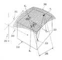
도 4는 3차원(3D) 어레이로서 또한 지칭되는 2개의 직교 방향들로 곡률을 갖는 오목한 곡선 매트릭스의 실시형태의 개략도이다. 3D 어레이 내의 각각의 엘리먼트는 x, y, 및 z 축들 모두에서 인접한 엘리먼트들에 대해 대체된다. 이러한 도면에서, 송신 어퍼쳐의 엘리먼트 또는 엘리먼트들은 매체에 인소니파이하도록 지정된다. 매체 내의 다수의 타겟들은 어떻게 체적(volumetric) 데이터가 수집될 수도 있는지를 나타내려는 목적을 위해 도시된다. 다중 수신 어퍼쳐들은, 데이터의 동시 수집이 사운드 조절들의 타이밍 및 조직 속도에 어떻게 관련될 수도 있는지를 나타내도록 도시된다.
도 4a는 3D 어레이의 실시형태를 개략적으로 도시한다. 다중의 송신 어퍼쳐들 T1 내지 TN은, 송신 펄스들이 하나 또는 그 초과의 수신 어퍼쳐들 R2 및/또는 R3 상에서 수신된다는 것을 나타내려는 목적을 위해 표시된다. 단일 타겟은 어떻게 데이터가 수집될 수도 있는지를 나타내려는 목적을 위해 표시된다.
도 4b는 x축을 따른 2D 장축(lognitudinal) 슬라이스에 대해 데이터를 수집하는데 사용되는 3D 어레이의 실시형태를 개략적으로 도시한다. 이러한 인스턴스(instance)에서, 횡축(transverse axis) z 내의 엘리먼트들의 라인이 송신 어퍼쳐 T1을 형성하는데 사용된다. 장축 슬라이스에 따른 데이터는 수신 어퍼쳐 R2에 위치된 엘리먼트들에 의해 수집될 수도 있다. 다중의 송신 어퍼쳐들은, 시간에 걸친 데이터 수집을 보조하기 위해 장축 슬라이스의 길이에 따라 사용될 수 있는 T1 내지 T5로서 식별된다. 동일한 횡축 슬라이스에 대한 동시 데이터, 또는 상이한 장축 슬라이스에 대한 별개의 데이터 중 어느 하나를 수집하는데 사용될 수 있는 또 다른 수신 어퍼쳐 R3가 표시된다.
도 4c는 z 축을 따른 2D 횡축 슬라이스에 대한 데이터를 수집하는데 사용되는 3D 어레이의 실시형태를 개략적으로 도시한다. 이러한 인스턴스에서, 장축 x 내의 엘리먼트들의 라인은 송신 어퍼쳐 T1을 형성하는데 사용된다. 횡축 슬라이스를 따른 데이터는 수신 어퍼쳐 R2에 위치된 엘리먼트들에 의해 수집될 수도 있다. 시간에 걸친 데이터 수집을 보조하기 위해 장축 슬라이스의 길이를 따라 사용될 수 있는 다중의 송신 어퍼쳐들 T1 내지 T5가 표시된다. 동일한 횡축 슬라이스에 대한 동시 데이터, 또는 상이한 횡축 슬라이스에 대한 별개의 데이터 중 어느 하나를 수집하는데 사용될 수 있는 또 다른 수신 어퍼쳐 R3가 표시된다.
도 4d는 체적 내에서 하이라이트된 데이터의 2D 장축 슬라이스를 갖는 데이터 체적을 도시한다. 이것은, 디스플레이 상의 동시 표현을 허용하기 위해 거의 실시간으로 더 높은 분해도의 2D 이미징과 체적 3D/4D 이미징을 상호교환하기 위한 다중 어퍼쳐 이미징의 능력을 도시한다.
도 4e는 체적 내에 하이라이트된 데이터의 2D 횡축 슬라이스를 갖는 데이터 체적을 도시한다. 이것은, 디스플레이 상의 표현을 허용하기 위해 거의 실시간으로 더 높은 분해도의 2D 이미징과 체적 3D/4D 이미징을 상호교환하기 위한 다중 어퍼쳐 이미징의 능력을 도시한다.
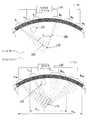
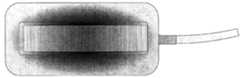
도 5는 비교적 큰 반경 곡률을 갖는 조직의 매체(예를 들어, 복부, 골반 등)에 걸친 오목한 곡선 프로브를 도시한 개략도이다.
도 5a는 도 5에 도시된 것과 같은 프로브 내의 곡선 어레이(예를 들어, 1D, 1.5D 또는 2D)의 실시형태의 하부도이다.
도 5b는 도 5에 도시된 것과 같은 프로브 내의 매트릭스 어레이(예를 들어, 2D 또는 3D)의 실시형태의 하부도이다.
도 5c는 도 5에 도시된 것과 같은 프로브 내의 CMUT 어레이의 실시형태의 하부도이다.
도 6은, 비교적 작은 반경 곡률을 갖는 조직의 매체(예를 들어, 팔, 다리, 목, 허리, 발목 등)에 걸친 오목한 곡선 프로브의 실시형태를 도시한 개략도이다.
도 6a는, 도 6의 어레이와 유사하지만 케이블 접속들이 프로브 하우징의 측면 상에 행해지게 하는 플렉스(flex) 접속들을 갖는 프로브 하우징 내에 있는 오목한 곡선 어레이의 실시형태의 개략도이다.
도 6b는 도 6 및 도 6a에 도시된 것들과 같은 프로브 내의 곡선 어레이(예를 들어, 1D, 1.5D 또는 2D)의 실시형태의 하부도이다.
도 6c는 도 6 및 도 6a에 도시된 것들과 같은 프로브 내의 곡선 매트릭스(예를 들어, 2D 또는 3D) 어레이의 실시형태의 하부도이다.
도 6d는 도 6 및 도 6a의 도시된 것들과 같은 프로브 내의 CMUT 어레이의 실시형태의 하부도이다.
도 7은 어레이의 장축과 정렬된 조정가능한 핸들을 갖는 도 6a의 프로브의 실시형태의 오목한 트랜스듀서 하우징의 평면도이다.
도 7a는 어레이의 횡축과 정렬된 조정가능한 핸들을 갖는 도 6a의 프로브의 실시형태의 오목한 트랜스듀서 하우징의 평면도이다.
도 7b는 비교적 큰-반경 곡률을 갖는 조직(예를 들어, 복부, 골반 등)의 매체를 통한 도 7a의 오목한 곡선 프로브를 도시한 측면 개략도이다.
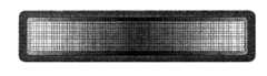
도 7c는 도 7a 내지 도 7b에 도시된 프로브 스타일들에 대한 사용에 이용가능한 곡선 어레이(예를 들어, 1D, 1.5D 또는 2D)의 하부도이다.
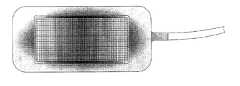
도 7d는 도 7a 내지 도 7b에 도시된 프로브 스타일들에 대한 사용에 이용가능한 매트릭스 어레이(예를 들어, 2D 또는 3D)의 하부도이다.
도 7e는 도 7a 내지 도 7b에 도시된 프로브 스타일에 대한 사용에 이용가능한 CMUT 어레이의 하부도이다.
도 7f는 도 7a 내지 도 7b에 도시된 것과 같은 프로브에서 사용된 바와 같은, 타원형 패턴으로 배열된 오목한 곡선의 트랜스듀서 어레이(에를 들어, 3D 또는 CMUT)의 하부도이다.
도 7g는 도 7h에 대한 섹션 라인을 식별하는 오목한 어레이 프로브 하우징의 평면도이다.
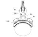
도 7h는 라인 A-B를 따라 취해진 도 7g의 오목한 어레이 프로브 하우징의 단면도이다. 이러한 실시형태는 프로브의 우측면 또는 하부 상의 플렉스 접속기들 및 케이블링 접속들을 도시한다. 캘리브레이션 칩, 동기화 모듈, 프로브 위치 대체 센서가 또한 프로브 핸들에 도시되어 있다.
도 8은 조정가능한 초음파 프로브의 실시형태를 도시한 다이어그램이다. 조정가능한 프로브의 이러한 버전은 5개의 어레이들을 가지며, 그 어레이들 각각은 연관된 플렉스 접속기를 갖는다. 캘리브레이션 칩, 동기화 모듈, 프로브 위치 대체 센서가 또한 프로브 핸들에 도시되어 있다.
도 8a는 원하는 생리부에 매칭하기 위해 커스텀 윤곽 배열로 배치된 도 8의 프로브의 5개의 어레이들을 도시한 다이어그램이다.
도 8b는 도 8의 프로브의 어레이들 중 2개의 단면도이며, 어레이들과 장력(tension) 케이블 사이의 조정가능한 힌지들의 실시형태의 세부사항들을 도시한다. 조정가능한 힌지들은 각각의 어레이의 후면 블록에 접속되는 것으로 도시되어 있다.
도 8c는 도 8에 도시된 것과 같은 프로브 내의 개별 어레이들(예를 들어, 1D 또는 1.5D)의 실시형태를 도시한 하부도이다.
도 8d는 도 8에 도시된 것과 같은 프로브 내의 매트릭스 어레이들(예를 들어, 2D)로서의 개별 어레이들의 실시형태를 도시한 하부도이다.
도 8e는 도 8에 도시된 것과 같은 프로브 내의 CMUT 어레이들로서의 개별 어레이들의 실시형태를 도시한 하부도이다.1 is a diagram of an ultrasound system control panel with aperture viewing angle and aperture width controls.
Figure 2 is a schematic diagram of a concave curved transducer array in which various elements are designated as transmit and receive apertures.
2A is a schematic diagram of a concave curved transducer array in which the elements are placed for use in a reciprocal transmission or reception function with respect to FIG.
Figure 2B is a schematic diagram of an embodiment of a concave curved transducer array in which the elements of the transmit and receive apertures are pre-designated to quickly and continuously insonify each other using similarly sized sizes of apertures.
2C is a schematic diagram of an embodiment of a concave curved transducer array that illustrates how transmit and receive apertures can be expanded around a desired viewing angle to achieve a larger exploded view of a target area.
3 is a schematic diagram of an embodiment of a concave curved transducer array illustrating pulses transmitted by a single designated transmission aperture and received by multiple designated reception apertures;
3A is a schematic diagram of an embodiment of a concave curved transducer array in which the transmit aperture and multiple receive apertures can be electronically controlled to operate at different positions.
4 is a schematic diagram of an embodiment of a concave curved matrix with curvature in two orthogonal directions, also referred to as a three-dimensional (3D) array. Each element in the 3D array is replaced for adjacent elements on both the x, y, and z axes. In this figure, the elements or elements of the transmission aperture are designated to insufficiently affect the medium. Multiple targets within a medium are shown for purposes of illustrating how volumetric data may be collected. Multiple receive apertures are shown to indicate how the simultaneous collection of data may be related to the timing and organization rate of the sound adjustments.
4A schematically illustrates an embodiment of a 3D array. The multiple transmit apertures T1 through TN are indicated for the purpose of indicating that transmit pulses are received on one or more receive apertures R2 and / or R3 . A single target is displayed for the purpose of indicating how data may be collected.
Figure 4b schematically illustrates an embodiment of a 3D array used to collect data for a 2D longitudinal log slice along the x axis. In this instance, a line of elements in the transverse axis z is used to form the transmission aperture T1 . The data along the long axis slice may be collected by the elements located in receive aperture R2 . The multiple transmit apertures are identified as T1 through T5 that can be used along the length of the long axis slice to aid in data collection over time. Another receive aperture R3 that can be used to collect either simultaneous data for the same transverse slice or separate data for different long axis slices is displayed.
Figure 4c schematically illustrates an embodiment of a 3D array used to collect data for 2D abscissa slices along the z-axis. In this instance, a line of elements within the major axis x is used to form the transmit aperture T1 . Data along the abscissa slice may be collected by the elements located in receive aperture R2 . To assist in the data acquisition over the time multiplex long axis of the upper, which can be used along the length of the slice is displayed watchers T1 to T5. Another receive aperture R3 that can be used to collect either simultaneous data for the same transverse slice, or separate data for different transverse slices is displayed.
4D shows a data volume having a 2D long axis slice of data highlighted in a volume. This illustrates the ability of multiple aperture imaging to interchange volumetric 3D / 4D imaging with higher resolution 2D imaging in near real time to allow simultaneous representation on the display.
Figure 4e shows a data volume having a 2D abscissa slice of data highlighted in volume. This illustrates the ability of multiple aperture imaging to interchange volumetric 3D / 4D imaging with higher resolution 2D imaging in near real time to allow representation on the display.
Figure 5 is a schematic diagram showing a concave curved probe across a medium of tissue (e.g., abdomen, pelvis, etc.) having a relatively large radial curvature.
5A is a bottom view of an embodiment of a curved array (e.g., 1D, 1.5D, or 2D) in a probe such as that shown in FIG.
5B is a bottom view of an embodiment of a matrix array (e.g., 2D or 3D) in a probe as shown in FIG.
5C is a bottom view of an embodiment of a CMUT array in a probe such as that shown in FIG.
Figure 6 is a schematic diagram illustrating an embodiment of a concave curved probe across a medium of tissue (e.g., an arm, a leg, a neck, a waist, an ankle, etc.) having a relatively small radius of curvature.
6A is a schematic diagram of an embodiment of a concave curved array in a probe housing similar to the array of FIG. 6, but with flex connections in which cable connections are made on the side of the probe housing.
6B is a bottom view of an embodiment of a curved array (e.g., 1D, 1.5D, or 2D) in a probe such as those shown in Figs. 6 and 6A.
Figure 6C is a bottom view of an embodiment of a curved matrix (e.g., 2D or 3D) array in a probe such as those shown in Figures 6 and 6A.
6D is a bottom view of an embodiment of a CMUT array in a probe such as those shown in Figs. 6 and 6A.
Figure 7 is a plan view of the concave transducer housing of the embodiment of the probe of Figure 6A with an adjustable handle aligned with the long axis of the array.
7A is a top view of the concave transducer housing of the embodiment of the probe of FIG. 6A with an adjustable handle aligned with the transverse axis of the array.
7B is a side schematic view illustrating the concave curved probe of FIG. 7A through the medium of a tissue having a relatively large-radius curvature (e.g., abdomen, pelvis, etc.).
7C is a bottom view of a curved array (e.g., 1D, 1.5D, or 2D) available for use with the probe styles shown in FIGS. 7A-7B.
7D is a bottom view of a matrix array (e.g., 2D or 3D) available for use with the probe styles shown in FIGS. 7A-7B.
7E is a bottom view of a CMUT array available for use with the probe styles shown in FIGS. 7A-7B.
Figure 7f is a bottom view of a concave curved transducer array (e.g., 3D or CMUT) arranged in an elliptical pattern, as used in a probe such as that shown in Figures 7a-7b.
7G is a top view of a concave array probe housing that identifies section lines for FIG. 7H.
Figure 7h is a cross-sectional view of the concave array probe housing of Figure 7g taken along line AB. This embodiment illustrates flex connectors and cabling connections on the right side or bottom of the probe. A calibration chip, synchronization module, probe position replacement sensor is also shown in the probe handle.
8 is a diagram showing an embodiment of an adjustable ultrasonic probe. This version of the adjustable probe has five arrays, each of which has an associated flex connector. A calibration chip, synchronization module, probe position replacement sensor is also shown in the probe handle.
8A is a diagram illustrating five arrays of probes of FIG. 8 arranged in a custom contour to match the desired physiology.
Figure 8b is a cross-sectional view of two of the arrays of probes of Figure 8 showing details of embodiments of adjustable hinges between the arrays and the tension cable. Adjustable hinges are shown connected to the rear block of each array.
8C is a bottom view showing an embodiment of individual arrays (e.g., 1D or 1.5D) in a probe as shown in FIG.
8D is a bottom view illustrating an embodiment of discrete arrays as matrix arrays (e.g., 2D) in a probe as shown in FIG.
8E is a bottom view illustrating an embodiment of individual arrays as CMUT arrays in a probe such as that shown in FIG.
여기에서의 몇몇 실시형태들은, 2 또는 3차원들의 실질적으로 연속적인 오목한 곡선 형상(즉, 이미징될 오브젝트에 관해 오목함)을 가질 수도 있는 초음파 트랜스듀서들의 연속적인 어레이들을 갖는 초음파 프로브들을 설계, 구축 및 사용하기 위한 시스템들 및 방법들을 제공한다. 여기에서의 다른 실시형태들은 조정가능한 프로브들 및 가변 구성들을 갖는 프로브들과 같은 다른 고유한 구성들을 갖는 초음파 이미징 프로브들을 설계, 구축 및 사용하기 위한 시스템들 및 방법들을 제공한다.Some embodiments herein are directed to designing and building ultrasonic probes having successive arrays of ultrasonic transducers that may have a substantially continuous concave curved shape of two or three dimensions (i.e., concave about the object to be imaged) And systems and methods for use. Other embodiments herein provide systems and methods for designing, constructing and using ultrasound imaging probes having other unique configurations, such as probes with adjustable probes and variable configurations.
다중 어퍼쳐 이미징 방법들과 결합된 캘리브레이팅된 다중 어퍼쳐 어레이 또는 어레이들의 사용은, 커스텀 형상된 오목한 또는 심지어 조정가능한 프로브들이 초음파 이미징에서 이용되게 한다. 추가적으로, "페이즈 내의" 연장된 페이즈된 어레이로부터의 정보를 유지하기 위해 종래의 직사각형 선형, 매트릭스 또는 용량성 마이크로머시닝된(micromachined) 초음파 트랜스듀서 또는 "CMUT" 어레이들에서의 다양한 단점들을 극복하기 위해 그리고 이미징 측면 분해도의 원하는 레벨을 달성하기 위해, 고유하게 형상된 초음파 프로브 솔루션들이 바람직하다.The use of calibrated multiple aperture arrays or arrays in combination with multiple aperture imaging methods allows custom shaped concave or even adjustable probes to be used in ultrasound imaging. Additionally, to overcome various disadvantages in conventional rectangular linear, matrix or capacitive micromachined ultrasonic transducers or "CMUT" arrays to retain information from an extended phased array in a "phase & In order to achieve the desired level of imaging lateral resolution, uniquely shaped ultrasonic probe solutions are preferred.
몇몇 실시형태들에서, 초음파 이미징 시스템은, 시야각, 빔 폭 및 어퍼쳐 사이즈의 수동 또는 자동 제어를 허용하도록 구성될 수도 있다. 이러한 특성은, 가스, 골격 또는 다른 초음파 불투명 구조들(예를 들어, 척추, 관절들, 말초 혈관, 흉강 내에 위치된 장기 등)에 의해 가려진 조직을 이미징하기를 시도할 경우 매우 유리할 수 있다. 관심 영역(region of interest) 위에 배치된 형상 프로브를 이용하여, 소노그래퍼는 타겟의 시야각을 제어할 수도 있다. 일단 원하는 시야각이 선택되면, 소노그래퍼는 원하는 깊이로 최상의 분해도를 달성하기 위해 어퍼쳐 폭을 전자적으로 제어할 수도 있다.In some embodiments, the ultrasound imaging system may be configured to allow manual or automatic control of viewing angle, beam width, and aperture size. This property can be very advantageous when attempting to image tissue obscured by gas, skeleton or other ultrasound opaque structures (e.g., vertebral, joints, peripheral blood vessels, organs located within the thoracic cavity, etc.). Using a shape probe disposed above a region of interest, the sonographer may control the viewing angle of the target. Once the desired viewing angle is selected, the sonographer may electronically control the aperture width to achieve the best resolution to the desired depth.
일 실시형태에서, (a) 펄스형 압전식 엘리먼트들이 인간의(또는 동물의) 조직으로 초음파 파들을 송신하기 위해 구성된 전자기기들; (b) 결과적인 에코 신호들을 수신하도록 구성된 전자기기들; (c) 이미지들을 형성하기 위해 에코 신호들을 프로세싱하도록 구성된 전자기기들; 및 (d) 수신 서브어퍼쳐 내에 복수의 수신 엘리먼트들을 갖는 프로브 - 코히런트 평균이 모든 경로들에 걸친 사운드 프로파일의 균일한 속도의 가정에 기초하여 사용될 경우, 산란기들로부터 수신 엘리먼트들 각각으로의 경로들에서의 사운드 변화들의 속도가 페이즈 소거를 회피하는데 충분히 작게 하기 위해 수신 서브어퍼쳐는 충분히 작음 - 를 갖는 의료용 초음파 장치가 존재한다. 부가적으로, 프로브는 송신 서브어퍼쳐 내에 송신 엘리먼트 또는 복수의 송신 엘리먼트들을 가질 수도 있으며, 송신 엘리먼트들 중 적어도 하나는 수신 서브어퍼쳐(들)와 분리되어 있다.In one embodiment, there is provided an apparatus comprising: (a) electronic devices configured to transmit ultrasonic waves into a human (or animal) tissue of pulsed piezoelectric elements; (b) electronic devices configured to receive the resulting echo signals; (c) electronic devices configured to process echo signals to form images; And (d) a path from the scatterers to each of the receiving elements, when a probe-coherent average with a plurality of receiving elements in the receiving sub-aperture is used based on an assumption of a uniform velocity of the sound profile over all paths, There is a medical ultrasound device having a receiving sub-aperture sufficiently small so that the speed of the sound changes in the receiving sub-aperture is sufficiently small to avoid phase cancellation. Additionally, the probe may have a transmitting element or a plurality of transmitting elements in the transmitting sub-aperture, and at least one of the transmitting elements is separate from the receiving sub-aperture (s).
또 다른 실시형태에서, 수신 서브어퍼쳐를 너무 크게 하여 페이즈 소거가 이미지를 열화시키게 하지 않으면서, 시스템의 측면 분해도를 결정하는 총 어퍼쳐 폭을 증가시키려는 목적을 위해 수신 서브어퍼쳐의 엘리먼트로부터 송신 엘리먼트들의 분리가 부과된다.In yet another embodiment, transmission from an element of the receiving sub-aperture is performed for the purpose of increasing the total aperture width, which determines the side resolution of the system, without making the receiving sub-aperture too large, Separation of elements is imposed.
또 다른 실시형태에서, 송신 엘리먼트들로부터 산란기들로의 경로들에서의 사운드 변화들의 속도가 (사운드의 일정한 공칭 속도를 가정하면, 이들 경로들에 따른 실제 송신 시간들과 이론적인 시간들 사이의 차이들이 실질적으로 작은 양만큼 서로 다르게 하기 위해) 충분히 작도록 송신 서브어퍼쳐는 충분히 작을 수도 있다. 몇몇 실시형태들에서, 실제 vs 이론적인 이동 시간들에서의 수용가능한 변화는 초음파 펄스의 하나의 기간보다 더 적다. 몇몇 실시형태들에서, 이미징 제어 전자기기는 단일 핑(ping)으로 이미징될 조직에 인소니파이하고, 빔포밍 및 이미징 프로세싱 전자기기들은 각각의 단일 핑에 의해 형성된 이미지들의 코히런트 부가에 의해 이미지들을 형성할 수도 있다. 다른 실시형태들에서, 빔포밍 및 이미지 프로세싱 전자기기들은 각각의 단일 핑에 의해 형성된 이미지들의 비코히런트 부가에 의해 이미지들을 형성할 수도 있다.In yet another embodiment, assuming that the speed of sound changes in the paths from the transmitting elements to the spawners (assuming a constant nominal speed of sound), the difference between the actual transmission times and the theoretical times according to these paths The transmission sub-apertures may be sufficiently small such that the transmission sub-apertures are sufficiently small (to make them substantially different by a small amount). In some embodiments, the acceptable change in actual vs theoretical travel times is less than one period of the ultrasonic pulse. In some embodiments, the imaging control electronics is insonophyte to tissue to be imaged with a single ping, and beamforming and imaging processing electronics form images by coherent addition of images formed by each single ping You may. In other embodiments, beamforming and image processing electronics may form images by noncoherent addition of images formed by each single ping.
이미징 송신 제어 전자기기들, 빔포밍 전자기기들 및 이미지 프로세싱 전자기기들은 여기서, 다중 어퍼쳐 초음파 이미징(또는 MAUI) 전자기기들로서 집합적으로 지칭될 수도 있다.Imaging transmission control electronics, beam-forming electronics, and image processing electronics may be collectively referred to herein as multiple aperture ultrasound imaging (or MAUI) electronics.
또 다른 실시형태에서, MAUI 전자기기는, 이미지들을 정렬시키기 위해 상호 상관과 같은 이미지 정렬을 사용하고 그 후, 비코히런트하게 이미지들을 부가함으로써 이미지들을 형성할 수도 있다.In another embodiment, the MAUI electronics may form images by using image alignment, such as cross-correlation, to align the images and then adding images non-coherently.
또 다른 실시형태에서, 송신 어퍼쳐는 반드시 작을 필요는 없으며, 수신 서브어퍼쳐를 포함할 수도 있다. MAUI 전자기기들은 단일 핑으로 이미징될 조직에 인소니파이할 수도 있고, 각각의 단일 핑에 의해 형성된 완성 이미지들의 비코히런트 부가에 의해 이미지들을 형성할 수도 있다. 더 추가적으로, MAUI 전자기기들은 이미지들을 정렬시키기 위해 상호 상관을 사용하고 그 후, 비코히런트하게 이미지들을 부가함으로써 이미지들을 형성하도록 구성될 수도 있다. 또 다른 실시형태에서, 시스템 제어기는, 상이한 그룹들로 형성된 이미지들이 감소된 잡음 및 아티팩트(artifact)들을 갖는 이미지들을 형성하도록 함께 평균될 수 있는 프로세싱 능력을 포함할 수도 있다.In yet another embodiment, the transmit aperture is not necessarily small and may include a receive sub-aperture. MAUI electronics may either insoneparate into the tissue to be imaged with a single ping or form images by the non-coherent portion of the finished images formed by each single ping. Still further, MAUI electronics may be configured to use the cross-correlation to align images and then form images by adding images non-coherently. In yet another embodiment, the system controller may include processing capabilities that can be averaged together to form images formed with different groups of images having reduced noise and artifacts.
여기에 설명된 개선점들은, 예를 들어, 일반적인 방사선학 오목하게 된 다중 어퍼쳐 프로브, 팔찌형 다중 어퍼쳐 프로브, 손바닥형 다중 어퍼쳐 프로브, 및 조정가능한 다중 어퍼쳐 프로브를 포함하는 광범위하게 다양한 프로브 타입들에 적용가능하다.The improvements described herein may be applied to a wide variety of probe types, including, for example, conventional radiologically concaved multiple aperture probes, bracelet multiple aperture probes, palm-like multiple aperture probes, and adjustable multiple aperture probes Lt; / RTI >
다른 대안적인 실시형태들에서, 본 발명의 양상들은 송신을 위해 포커싱되지 않은 핑들을 사용하기 위해 제공되며, 송신 어퍼쳐는 수신 어퍼쳐보다 훨씬 더 폭이 넓을 수 있고, 그것을 둘러싸을 수 있다.In other alternative embodiments aspects of the present invention are provided for use of unfocused pings for transmission and the transmission aperture may be much wider than the receive aperture and may surround it.
부가적인 실시형태들에서, 하나의 어퍼쳐만의 수신 엘리먼트들은, 코히런트하게 평균된 이미지를 달성하기 위해 사운드 정정의 속도를 사용하지 않으면서, 송신 펄스 또는 파가 수신 엘리먼트의 어퍼쳐 외부에 그리고 떨어져 위치된 엘리먼트 또는 엘리먼트들의 어레이로부터 도래하는 경우 이미지를 구성하는데 사용될 수 있다.In additional embodiments, the receive elements of only one aperture may use a velocity of the sound correction to achieve a coherently averaged image such that the transmit pulse or wave is outside the aperture of the receive element and May be used to construct an image when it comes from an array of spaced apart elements or elements.
여기에서의 수 개의 실시형태들이 의료용 초음파 이미징을 참조하여 설명되지만, 당업자는 여기에서의 실시형태들의 특성들 및 이점들이 또한 비-의료용 초음파 이미징 애플리케이션들 또는 초음파의 비-이미징 애플리케이션들에서 달성될 수도 있음을 인식할 것이다.Although several embodiments herein are described with reference to medical ultrasound imaging, those skilled in the art will appreciate that the features and advantages of the embodiments herein may also be accomplished in non-medical ultrasound imaging applications or in ultrasonic non-imaging applications .
여기에 사용된 바와 같이, "초음파 트랜스듀서" 및 "트랜스듀서" 라는 용어들은 초음파 이미징 기술들의 당업자들에 의해 이해되는 바와 같은 그들 본래의 의미들을 운반할 수도 있으며, 전기 신호를 초음파 신호로 및/또는 초음파 신호를 전기 신호로 변환할 수 있는 임의의 단일 컴포넌트를 제한없이 지칭할 수도 있다. 예를 들어, 몇몇 실시형태들에서, 초음파 트랜스듀서는 압전식 디바이스를 포함할 수도 있다. 다른 실시형태들에서, 초음파 트랜스듀서들은 용량성 마이크로머시닝된 초음파 트랜스듀서들(CMUT)을 포함할 수도 있다.As used herein, the terms "ultrasonic transducer" and "transducer" may convey their natural meanings as understood by those skilled in the art of ultrasound imaging techniques, Or any single component capable of converting an ultrasonic signal into an electrical signal. For example, in some embodiments, the ultrasonic transducer may include a piezoelectric device. In other embodiments, the ultrasonic transducers may comprise capacitive micromachined ultrasonic transducers (CMUT).
트랜스듀서들은 종종 다수의 개별 트랜스듀서 엘리먼트들의 어레이들로 구성된다. 여기에 사용된 바와 같이, "트랜스듀서 어레이" 또는 "어레이" 라는 용어들은 일반적으로, 일반적인 후면 플레이트에 탑재된 트랜스듀서 엘리먼트들의 집합을 지칭한다. 그러한 어레이들은 1차원(1D), 2차원(2D), 1.5차원(1.5D) 또는 3차원(3D)을 가질 수도 있다. 당업자들에 의해 이해되는 바와 같은 다른 차원의 어레이들이 또한 사용될 수도 있다. 트랜스듀서 어레이들은 또한, CMUT 어레이들일 수도 있다. 트랜스듀서 어레이의 엘리먼트는 어레이의 가장 작은 별개의 기능 컴포넌트일 수도 있다. 예를 들어, 압전식 트랜스듀서 엘리먼트들의 어레이의 경우, 각각의 엘리먼트는 단일의 압전식 크리스탈 또는 압전식 크리스탈의 단일의 머시닝된 섹션일 수도 있다.The transducers are often comprised of arrays of a plurality of discrete transducer elements. As used herein, the terms "transducer array" or "array" generally refer to a collection of transducer elements mounted on a common back plate. Such arrays may have one dimension (1D), two dimensions (2D), 1.5 dimensions (1.5D), or three dimensions (3D). Other dimensions of arrays as understood by those skilled in the art may also be used. The transducer arrays may also be CMUT arrays. The elements of the transducer array may be the smallest separate functional components of the array. For example, in the case of an array of piezoelectric transducer elements, each element may be a single piezoelectric crystal or a single machined section of a piezoelectric crystal.
2D 어레이는, 초음파 트랜스듀서 엘리먼트들의 그리드를 포함하는 실질적으로 평면인 구조를 지칭하는 것으로 이해될 수 있다. 그러한 2D 어레이는, 어레이의 표면을 따라 행들 및 열들로 배열된 복수의 개별 엘리먼트들(정사각형, 직사각형 또는 임의의 다른 형상일 수도 있음)을 포함할 수도 있다. 종종, 2D 어레이는 엘리먼트 섹션들을 압전식 크리스탈로 절단함으로써 형성된다.The 2D array may be understood to refer to a substantially planar structure comprising a grid of ultrasonic transducer elements. Such a 2D array may include a plurality of discrete elements (which may be square, rectangular or any other shape) arranged in rows and columns along the surface of the array. Often, a 2D array is formed by cutting the element sections into piezoelectric crystals.
여기에 사용된 바와 같이, 곡선의 1D, 1.5D 또는 2D 트랜스듀서 어레이들에 대한 참조는, 하나의 축(예를 들어, 직사각형 어레이의 횡축)만에 대한 곡률을 갖는 곡선의 표면들을 가진 초음파 트랜스듀서 어레이들을 설명하도록 의도된다. 따라서, 1D, 1.5D 또는 2D 곡선의 어레이들의 실시형태들은 부분적인 원통형 섹션들로서 설명될 수도 있다.As used herein, references to curved 1D, 1.5D, or 2D transducer arrays refer to ultrasonic transducers having curved surfaces with curvature only for one axis (e.g., the transverse axis of a rectangular array) It is intended to illustrate ducer arrays. Thus, embodiments of arrays of 1D, 1.5D, or 2D curves may be described as partial cylindrical sections.
여기에 사용된 바와 같이, "3D 어레이" 또는 "3D 곡선 어레이" 라는 용어는 2개 또는 그 초과의 축들(예를 들어, 직사각형 어레이의 횡축 및 장축 양자)에 관한 곡률을 갖는 곡선의 표면을 가진 임의의 초음파 트랜스듀서 어레이를 설명하는 것으로 이해될 수도 있다. 3D 곡선 어레이의 엘리먼트들은 3차원으로 모든 인접한 엘리먼트들에 대해 대체될 수도 있다. 따라서, 3D 곡선 어레이들은 포물선 또는 구 표면의 섹션과 같은 3차원 2차 표면 형상을 갖는 것으로 설명될 수도 있다. 몇몇 경우들에서, 3D 어레이라는 용어는 머시닝된 압전식 어레이들에 부가하여 곡선의 CMUT 어레이들을 지칭할 수도 있다.As used herein, the term "3D array" or "3D curved array" refers to a curved surface having curvatures with respect to two or more axes (e.g., both the transverse axis and the major axis of a rectangular array) May be understood to describe any ultrasonic transducer array. Elements of the 3D curve array may be substituted for all adjacent elements in three dimensions. Thus, 3D curve arrays may be described as having a three dimensional secondary surface shape, such as a section of a parabolic or spherical surface. In some cases, the term 3D array may refer to curved CMUT arrays in addition to the machined piezoelectric arrays.
여기에 사용된 바와 같이, "송신 엘리먼트" 및 "수신 엘리먼트" 라는 용어들은, 초음파 이미징 기술들의 당업자에 의해 이해되는 바와 같이 그들 본래의 의미들을 운반할 수도 있다. "송신 엘리먼트" 라는 용어는, 전기 신호가 초음파 신호로 변환되는 송신 기능을 적어도 잠시 수행하는 초음파 트랜스듀서 엘리먼트를 제한없이 지칭할 수도 있다. 유사하게, "수신 엘리먼트" 라는 용어는, 엘리먼트에 닿은 초음파 신호가 전기 신호로 변환되는 수신 기능을 적어도 잠시 수행하는 초음파 트랜스듀서 엘리먼트를 제한없이 지칭할 수도 있다. 초음파의 매체로의 송신은 또한 "인소니파이하는 것" 으로서 여기에 지칭될 수도 있다. 초음파 파들을 반사하는 물체 또는 구조는 "반사기" 또는 "산란기" 로서 지칭될 수도 있다.As used herein, the terms "transmitting element" and "receiving element" may carry their natural meanings as understood by those skilled in the art of ultrasound imaging techniques. The term "transmitting element" may refer unrestrictedly to an ultrasonic transducer element that performs at least a moment in the transmitting function in which an electrical signal is converted into an ultrasonic signal. Similarly, the term "receiving element" may refer unrestrictedly to an ultrasonic transducer element that performs at least a moment in time the receiving function in which the ultrasonic signal in contact with the element is converted into an electrical signal. Transmission of ultrasound to media may also be referred to herein as "insonophil ". An object or structure that reflects ultrasonic waves may be referred to as a "reflector" or "spawner ".
여기에 사용된 바와 같이, "어퍼쳐" 라는 용어는, 초음파 신호들이 전송 및/또는 수신될 수도 있는 개념적인 "개구" 를 지칭할 수도 있다. 실제의 실시에서, 어퍼쳐는 간단히, 이미징 제어 전자기기들에 의해 공통 그룹으로서 집합적으로 관리되는 트랜스듀서 엘리먼트들의 그룹이다. 예를 들어, 몇몇 실시형태들에서, 어퍼쳐는, 인접한 어퍼쳐의 엘리먼트들과 물리적으로 분리될 수도 있는 엘리먼트들의 물리적 그룹화일 수도 있다. 그러나, 인접한 어퍼쳐들은 반드시 물리적으로 분리될 필요는 없다.As used herein, the term " aperture "may refer to a conceptual" aperture "in which ultrasound signals may be transmitted and / or received. In actual practice, the aperture is simply a group of transducer elements that are collectively managed as a common group by the imaging control electronics. For example, in some embodiments, the aperture may be a physical grouping of elements that may be physically separated from the elements of the adjacent aperture. However, adjacent apertures do not necessarily have to be physically separated.
"수신 어퍼쳐", "인소니파이 어퍼쳐", 및/또는 "송신 어퍼쳐" 라는 용어들이, 원하는 물리적 관점 또는 어퍼쳐로부터 원하는 송신 또는 수신 기능을 수행하는 개별 엘리먼트, 어레이 내의 엘리먼트들의 그룹, 또는 심지어 공통 하우징 내의 전체 어레이들을 의미하도록 여기에 사용됨을 유의해야 한다. 몇몇 실시형태들에서, 그러한 송신 및 수신 어퍼쳐들은 전용 기능을 갖는 물리적으로 분리된 컴포넌트들로서 생성될 수도 있다. 다른 실시형태들에서, 임의의 수의 전송 및/또는 수신 어퍼쳐들은 필요할 때 전자적으로 동적으로 정의될 수도 있다. 다른 실시형태들에서, 다중 어퍼쳐 초음파 이미징 시스템은 전용-기능 및 동적-기능 어퍼쳐들의 결합을 사용할 수도 있다.The terms "receive aperture," " insonophiter aperture, "and / or" transmit aperture "refer to individual elements that perform the desired transmit or receive function from a desired physical view or aperture, Are used herein to mean even the entire array within the common housing. In some embodiments, such transmit and receive apertures may be generated as physically separate components having dedicated functionality. In other embodiments, any number of transmit and / or receive apertures may be defined electronically dynamically as needed. In other embodiments, the multi-aperture ultrasound imaging system may use a combination of dedicated-function and dynamic-function apertures.
여기에 사용된 바와 같이, "총 어퍼쳐" 라는 용어는 모든 이미징 어퍼쳐들의 총 누적 사이즈를 지칭한다. 즉, "총 어퍼쳐" 라는 용어는 특정한 이미징 사이클에 대해 사용된 전송 및/또는 수신 엘리먼트들의 임의의 결합의 가장 먼 트랜스듀서 엘리먼트들 사이의 최대 거리에 의해 정의된 하나 또는 그 초과의 차원들을 지칭할 수도 있다. 따라서, 총 어퍼쳐는 특정한 사이클에 대한 전송 또는 수신 어퍼쳐들로서 지정된 임의의 수의 서브-어퍼쳐들로 구성된다. 단일-어퍼쳐 이미징 배열의 경우에서, 총 어퍼쳐, 서브-어퍼쳐, 송신 어퍼쳐, 및 수신 어퍼쳐 모두는 동일한 차원들을 가질 것이다. 다중 어퍼쳐 이미징 배열의 경우에서, 총 어퍼쳐의 차원들은 모든 전송 및 수신 어퍼쳐들의 차원들의 합을 포함한다.As used herein, the term "total aperture " refers to the total cumulative size of all imaging apertures. That is, the term "total aperture" refers to one or more dimensions defined by the maximum distance between the furthest transducer elements of any combination of transmit and / or receive elements used for a particular imaging cycle You may. Thus, the total aperture consists of any number of sub-aperters designated as transmit or receive apertures for a particular cycle. In the case of a single-aperture imaging array, both the total aperture, the sub-aperture, the transmission aperture, and the receive aperture will have the same dimensions. In the case of a multiple aperture imaging array, the dimensions of the total aperture contain the sum of the dimensions of all transmit and receive apertures.
몇몇 실시형태들에서, 2개의 어퍼쳐들은 연속하는 어레이 상에서 서로 인접하게 위치될 수도 있다. 또 다른 실시형태들에서, 2개의 어퍼쳐들은 연속하는 어레이 상에서 서로 중첩할 수도 있으므로, 적어도 하나의 엘리먼트는 2개의 분리된 어퍼쳐들의 일부로서 기능한다. 엘리먼트들의 위치, 기능, 수 및 어퍼쳐의 물리 사이즈는 특정한 애플리케이션에 대해 필요한 임의의 방식으로 동적으로 정의될 수도 있다. 특정한 애플리케이션에 대한 이들 파라미터들에 관한 제한들은 후술될 것이고 및/또는 당업자에게는 명백할 것이다.In some embodiments, the two apertures may be positioned adjacent to each other on successive arrays. In still other embodiments, the two apertures may overlap one another on successive arrays, so that at least one element functions as part of two separate apertures. The location, function, number of elements, and physical size of the aperture may be dynamically defined in any manner necessary for a particular application. Limitations on these parameters for a particular application will be discussed below and / or will be apparent to those skilled in the art.
다중 어퍼쳐 초음파 이미징 기술들은 초음파 송신 및 수신 기능들의 물리적 및 논리적 분리로부터 실질적으로 이득을 얻을 수 있다. 몇몇 실시형태들에서, 그러한 시스템들은 또한, 송신 어퍼쳐로부터 물리적으로 이격될 수도 있는 2개 또는 그 초과의 분리된 수신 어퍼쳐들에서 실질적으로 동시에 에코들을 수신하기 위한 능력으로부터 실질적으로 이득을 얻을 수도 있다. 추가적인 이점들은 송신 어퍼쳐의 엘리먼트들과는 상이한 스캔 평면 상에 위치된 하나 또는 그 초과의 수신 어퍼쳐들을 사용함으로써 달성될 수도 있다.Multiple aperture ultrasound imaging techniques may substantially benefit from physical and logical separation of ultrasonic transmission and reception functions. In some embodiments, such systems may also substantially benefit from the ability to receive echoes at substantially the same time in two or more separate receive apertures that may be physically spaced from the transmit aperture . Additional advantages may be achieved by using one or more receive apertures located on a scan plane that is different from the elements of the transmit aperture.
여기에 설명된 엘리먼트들 및 어레이들은 또한 멀티-기능일 수도 있다. 즉, 일 인스턴스에서 송신기들로서의 트랜스듀서 엘리먼트들 또는 어레이들의 지정은, 다음의 인스턴스에서의 수신기들로서의 그들의 즉시 재지정을 배제하지는 않는다. 또한, 여기에서의 제어 시스템의 실시형태들은, 사용자 입력들, 미리-셋팅된 스캔 또는 분해도 기준들, 또는 다른 자동적으로 결정된 기준들에 기초하여 그러한 지정들을 전자적으로 행하기 위한 능력들을 포함한다.The elements and arrays described herein may also be multi-functional. That is, the assignment of transducer elements or arrays as transmitters in one instance does not preclude their immediate redirection as receivers in the next instance. In addition, embodiments of the control system herein include the ability to electronically make such assignments based on user inputs, pre-set scan or resolution standards, or other automatically determined criteria.
몇몇 실시형태들에서, 수신 어퍼쳐에서 검출된 각각의 에코는 이미징 전자기기들 내의 휘발성 또는 비-휘발성 메모리에 별개로 저장될 수도 있다. 수신 어퍼쳐에서 검출된 에코들이 인소니파이 어퍼쳐로부터의 각각의 펄스에 대해 별개로 저장되면, 전체의 2차원 이미지가 단지 하나의 엘리먼트만큼 적은 엘리먼트에 의해 수신된 정보로부터 형성될 수 있다. 이미지의 부가적인 카피들은, 인소니파이 펄스들의 동일한 세트로부터 데이터를 수집하는 부가적인 수신 어퍼쳐들에 의해 형성될 수 있다. 궁극적으로, 다수의 이미지들은, 하나 또는 그 초과의 어퍼쳐들로부터 실질적으로 동시에 생성될 수 있고, 종합적인 2D 또는 3D 이미지를 달성하도록 결합될 수 있다.In some embodiments, each echo detected in the receive aperture may be stored separately in volatile or non-volatile memory in imaging electronics. If the echoes detected in the receive aperture are stored separately for each pulse from the incipient aperture, the entire two-dimensional image can be formed from information received by as few as one element. Additional copies of the image may be formed by additional receive apertures that collect data from the same set of insoniferous pulses. Ultimately, multiple images can be generated substantially simultaneously from one or more apertures, and combined to achieve a comprehensive 2D or 3D image.
다중 어퍼쳐 초음파 이미징(MAUI) 방법들 및 시스템들은 상기 참조된 출원인의 이전의 US 특허 출원들에서 이전에 소개되었다. 이들 출원들은, 완성된 2D 이미지가 형성될 수 있는 독립적인 어퍼쳐로서 각각의 개별 수신 엘리먼트를 고려하는 실시형태들을 포함한 다중 어퍼쳐 이미징 기술들 및 시스템들을 설명한다. 많은 그러한 수신 어퍼쳐들은 동일한 2D 이미지의 많은 재구성들을 형성할 수 있지만, 상이한 포인트 확산 기능들 및 상이한 잡음 컴포넌트들을 갖는다. 이들 이미지들의 결합은 측면 분해도 및 스페클(speckle) 잡음의 감소 양자의 관점들에서 많이-개선된 전체 이미지를 제공한다.Multiple aperture ultrasound imaging (MAUI) methods and systems have been previously disclosed in the above-referenced applicants' prior US patent applications. These applications describe multiple aperture imaging techniques and systems that include embodiments that consider each individual receiving element as an independent aperture upon which a completed 2D image can be formed. Many such receiving apertures can form many reconstructions of the same 2D image, but have different point spreading functions and different noise components. The combination of these images provides a much-improved overall image in terms of both side view and reduced speckle noise.
출원인의 이전의 출원들에 설명된 바와 같이, 다중의 수신 어퍼쳐들로부터의 이미지들이 코히런트하게 결합되기 위해, 송신 엘리먼트(들)(또는 프로브에 대한 몇몇 다른 고정 좌표 시스템)에 대한 각각의 엘리먼트의 상대적인 음향 위치가 원하는 정확도로 정확히 알려져야 한다. 종래에는, 트랜스듀서 엘리먼트들의 위치가 통상적으로, 엘리먼트를 형성하는 구조의 지리적 중심에 대응한다고 가정된다. 예를 들어, 종래의 1D 페이즈된 어레이 프로브의 경우에서, 엘리먼트들의 기계적 위치는 도 6b에서 크리스탈 웨이퍼(110) 내부의 절단들의 사이즈에 의해 결정될 수도 있다. 음향 중심은 일반적으로, 형상된 크리스탈라인 구조의 중심에 있는 것으로 가정된다 (예를 들어, 도 6b의 엘리먼트들(120)의 중간 위치로 내려가는 포물선 채널).(Or some other fixed coordinate system for the probe) to coherently combine images from multiple receive apertures, as described in Applicants' prior applications. Relative acoustic positions should be known accurately to the desired accuracy. It is conventionally assumed that the position of the transducer elements typically corresponds to the geographic center of the structure forming the element. For example, in the case of a conventional 1D phased array probe, the mechanical location of the elements may be determined by the size of the cuts inside the
그러나, 트랜스듀서 엘리먼트들의 음향 위치는 반드시 그들의 지리적 또는 기계적 위치들에 정확히 대응할 필요는 없을 수도 있다. 따라서, 몇몇 실시형태들에서, 어레이 내의 각각의 엘리먼트의 실제 음향 위치는 출원인들의 이전 출원들에 설명된 바와 같이, 캘리브레이션 시스템 및 프로세스에 의해 결정될 수 있다.However, the acoustic positions of the transducer elements may not necessarily correspond exactly to their geographic or mechanical locations. Thus, in some embodiments, the actual acoustic location of each element in the array may be determined by the calibration system and process, as described in applicants' previous applications.
실질적인 이미징 및 실시 사용 이점들은, 오목한 곡선의 초음파 트랜스듀서 어레이를 이용하여 다수의 어퍼쳐 이미징 프로세스들을 사용함으로써 달성될 수도 있다. 몇몇 실시형태들에서, 오목한 트랜스듀서 어레이는, 예를 들어, 도 6에 도시된 바와 같이 비교적 큰 곡률 반경을 가질 수도 있다. 다른 실시형태들에서, 예를 들어, 도 7에 도시된 바와 같이, 오목한 트랜스듀서 어레이는 비교적 작은 곡률 반경을 가질 수도 있다. 몇몇 실시형태들에서, 그러한 오목한 곡률은 도시된 바와 같이 실질적으로 연속일 수도 있거나, 유사한 오목한 구조는 복수의 선형 세그먼트들을 결합함으로써 형성될 수도 있다. 적절한 캘리브레이션을 이용하여, 사실상 임의의 어레이 형상이 형성 및 이용될 수도 있다.Practical imaging and implementation use advantages may be achieved by using a plurality of aperture imaging processes using a concave curved ultrasonic transducer array. In some embodiments, the concave transducer array may have a relatively large radius of curvature, for example, as shown in FIG. In other embodiments, for example, as shown in Figure 7, the concave transducer array may have a relatively small radius of curvature. In some embodiments, such concave curvature may be substantially continuous as shown, or a similar concave structure may be formed by combining a plurality of linear segments. With appropriate calibration, virtually any array shape may be formed and utilized.
다음의 실시형태들이 단일의 연속적인 트랜스듀서 어레이를 참조하여 설명되지만, 당업자는, 동일한 기본적인 구조들, 특성들 및 이점들이, 원할 때 평면 또는 곡선 형상을 각각 가질 수도 있는 복수의 별개의 트랜스듀서 어레이들을 사용함으로써 달성될 수도 있음을 인식할 것이다. 따라서, 임의의 수의 엘리먼트들 또는 블록들의 어레이들이 여기에 설명된 시스템들 및 방법들을 사용하여 다중 어퍼쳐 프로브에서 사용될 수도 있음을 인식할 것이다.Although the following embodiments are described with reference to a single continuous transducer array, those skilled in the art will appreciate that the same basic structures, characteristics, and advantages may be achieved by a plurality of discrete transducer arrays, each of which may have a planar or curved shape, ≪ / RTI > Thus, it will be appreciated that any number of elements or arrays of blocks may be used in multiple aperture probes using the systems and methods described herein.
더 상세히 후술될 바와 같이, 몇몇 실시형태들에서, 오목한 초음파 이미징 프로브는 다수의 고유한 조정 및 제어 파라미터들을 갖는 이미징 제어 전자기기들과 결합하여 사용될 수도 있다. 예를 들어, 적절한 제어 전자기기들과 결합하여 실질적으로 연속하는 오목한 곡선의 트랜스듀서 어레이를 제공함으로써, 송신 및/또는 수신 어퍼쳐들의 물리적 위치가 프로브를 이동시키지 않으면서 동적으로 변경될 수도 있다. 부가적으로, 송신 및/또는 수신 어퍼쳐에 할당된 엘리먼트들의 사이즈 및 수가 동적으로 변경될 수도 있다. 그러한 조정들은 오퍼레이터가 사용 및 환자 생리부에서의 광범위한 범위의 변화들에 대해 시스템을 적응시키게 할 수도 있다.As will be described in more detail below, in some embodiments, concave ultrasound imaging probes may be used in combination with imaging control electronics having a number of unique adjustment and control parameters. For example, by providing a substantially continuous, concave curved transducer array in combination with appropriate control electronics, the physical location of the transmit and / or receive apertures may be dynamically changed without moving the probe. Additionally, the size and number of elements assigned to the transmit and / or receive apertures may be changed dynamically. Such adjustments may allow the operator to adapt the system to a wide range of changes in use and patient physiology.
도 1은, 어레이(들)를 이용하여 초음파 이미징을 구동 및 제어하도록 구성된 적어도 하나의 초음파 이미징 어레이 및 제어 시스템에 대한 사용을 위해 구성된 다중 어퍼쳐 초음파 이미징 시스템 제어 패널의 실시형태를 도시한다. 제어 시스템은 MAUI 전자기기들로서 여기에 지칭될 수 있으며, 컴퓨터 프로세서, 메모리, 펄스 생성기, 임의의 부착된 초음파 어레이들을 제어하도록 구성된 소프트웨어로서 그러한 특성들을 포함할 수 있다. MAUI 전자기기들은 본 명세서 전반에 걸쳐 예시되며, 여기에 도시된 초음파 어레이들의 다양한 실시형태들이 MAUI 전자기기들에 의해 각각 구동 및 제어될 수 있음을 이해해야 한다. 몇몇 실시형태들에서, MAUI 제어 패널은 어퍼쳐 시야각 제어(410) 및 어퍼쳐 폭 제어(420)와 같은 어퍼쳐 제어들을 포함할 수도 있다. MAUI 제어 패널은 또한, 각각의 송신 어퍼쳐 및 각각의 수신 어퍼쳐에 대해 사용되는 엘리먼트들의 수를 조정하도록 구성된 엘리먼트 제어들(430 및 440)을 각각 포함할 수도 있다. 몇몇 실시형태들에서, 제어들(410, 420, 430, 440)은 버튼들, 손잡이들, 스크롤 휠들, 트랙볼들, 터치 패드들, 슬라이더들 또는 임의의 다른 적절한 휴면 인터페이스 디바이스를 포함할 수도 있다.1 shows an embodiment of a multi-aperture ultrasound imaging system control panel configured for use with at least one ultrasound imaging array and control system configured to drive and control ultrasonic imaging using the array (s). The control system may be referred to herein as MAUI electronics and may include such features as software configured to control a computer processor, a memory, a pulse generator, and any attached ultrasonic arrays. MAUI electronics are illustrated throughout this disclosure, and it should be appreciated that the various embodiments of the ultrasound arrays illustrated herein may be driven and controlled by MAUI electronics, respectively. In some embodiments, the MAUI control panel may include aperture controls such as aperture
도 2는 단일의 다중 어퍼쳐 초음파 이미징 사이클 동안 초음파 트랜스듀서 엘리먼트들의 오목한 곡선 어레이의 일 실시형태를 도시한다. 이러한 도면에서, 송신 어퍼쳐 T1 내의 하나 또는 그 초과의 엘리먼트들은 에너지를 매체로 송신하는 것으로 도시되어 있다. 송신 빔포밍은 페이즈된 어레이를 이용할 수도 있거나 단일 핑일 수도 있다. 어느 경우이든, 에너지는 적어도 하나의 반사기(170)를 갖는 관심 영역을 향해 송신된다. 수신 어퍼쳐 엘리먼트들 R1은 MAUI 전자기기(140)에 의해 이러한 송신 사이클 동안 데이터를 수집하도록 전자적으로 지정될 수도 있다.Figure 2 illustrates one embodiment of a concave curved array of ultrasonic transducer elements during a single multiple aperture ultrasound imaging cycle. In this figure, one or more elements in the transmission aperture T1 are shown transmitting energy to the medium. The transmit beamforming may utilize a phased array or may be a single ping. In either case, the energy is transmitted towards the region of interest having at least one
각각의 엘리먼트의 위치를 정의하는 캘리브레이팅된 음향 위치 데이터에 기초하여, 이러한 캡쳐 기간 동안 송신 어퍼쳐 T1의 엘리먼트(들)로부터의 R1 내의 모든 수신 엘리먼트들의 개별 거리들은 펌웨어 또는 하드웨어에서 계산될 수도 있다. 이것은, 수신 어퍼쳐 R1로부터의 데이터가 수신 시에 즉시 실시간으로, 정렬된 이미지로 어셈블리되게 한다.Based on the calibrated acoustic position data defining the location of each element, the individual distances of all the receive elements in R1 from element (s) of transmit aperture T1 during this capture period are calculated in firmware or hardware . This causes the data from the receive aperture R1 to be assembled into an aligned image in real time immediately upon reception.
종래의 페이즈된 어레이 프로브의 단일 어퍼쳐의 사이즈(예를 들어, 폭) 및 그에 따른 분해도는 트랜스듀서와 관심있는 장기 사이의 조직에서의 사운드의 속도의 변화에 의해 매우 제한될 수 있다. 몸 전반에 걸친 다양한 연조직들에서의 사운드의 속도가 ±10% 만큼 변할 수 있지만, 사운드의 속도가 트랜스듀서와 관심있는 장기 사이의 경로에서 일정하다고 일반적으로 가정된다. 이러한 가정은, 하나의 트랜스듀서 어레이(예를 들어, 송신 및 수신 양자를 위해 사용된 단일 어레이)를 사용하는 시스템들에서 협소한 트랜스듀서 어레이들에 대해 유효하다. 그러나, 사운드의 일정한 속도 가정은, 초음파 펄스들이 더 많은 조직 및 가능하면 다양한 타입들의 조직을 통과하기 때문에, 프로브의 총 어퍼쳐가 더 넓게 될 경우 붕괴된다. 트랜스듀서 어레이의 길이 하의 조직 다양성은 송신 및 수신 기능들 양자에 영향을 줄 수도 있다.The size (e.g., width) and the degree of degradation of a single aperture of a conventional phased array probe can be very limited by changes in the speed of sound in the tissue between the transducer and the organ of interest. Although the speed of sound in various soft tissues throughout the body may vary by +/- 10%, it is generally assumed that the speed of sound is constant in the path between the transducer and the organ of interest. This assumption is valid for narrow transducer arrays in systems that use a single transducer array (e.g., a single array used for both transmit and receive). However, the constant velocity assumption of sound collapses when the total aperture of the probe becomes wider, because the ultrasonic pulses pass through more tissue and possibly various types of tissue. The tissue diversity under the length of the transducer array may affect both transmit and receive functions.
도 2의 반사기(170)와 같은 반사기가 송신 엘리먼트들의 그룹으로부터의 포커싱된 펄스 또는 단일 송신 엘리먼트로부터의 핑 중 어느 하나에 의해 인소니파이될 경우, 반사기(170)는 지정된 수신 어퍼쳐 R1의 엘리먼트들 모두에 에코를 다시 반사한다. 반사기(170)로부터 R1 내의 수신기 엘리먼트들 각각으로의 경로들에서의 사운드의 속도 변화들이 기준으로서 선택된 하나의 경로에 대한 +-180 도 페이즈 시프트를 초과하지 않으면, 이러한 수신 어퍼쳐 내의 엘리먼트들에 의해 수집된 이미지들의 코히런트 부가는 효율적일 수 있다.If the reflector, such as the
코히런트 부가가 효율적일 수 있는 어퍼쳐 R1의 최대 물리 사이즈는, 환자 내의 조직 변화에 의존하며, 미리 정확히 계산될 수 없다. 종래의 초음파 이미징 시스템들은 통상적으로, 광범위한 범위의 기대된 사용들에 대한 페이즈 충돌들을 회피하기 위해 광범위한 범위의 가능한 환자들, 연구들 및 시야각들에 대해 타협된 어퍼쳐 폭을 이용하여 설계된다. 그러나, 그들이 타협을 수반하기 때문에, 그러한 종래의 프로브들은 반드시 최적의 이미지를 생성하지는 않는다. 페이즈 코히런트는, 포커싱된 송신 빔을 생성하기 위해 엘리먼트들의 그룹을 사용할 경우 동등하게 중요하며, 종종 종래의 트랜스듀서 어레이 폭들 및 동작에서 다시 타협한다.The maximum physical size of aperture R1 , where the coherent addition may be effective, depends on tissue changes within the patient and can not be accurately calculated in advance. Conventional ultrasound imaging systems are typically designed using a compromised aperture width for a wide range of possible patients, studies, and viewing angles to avoid phase collisions for a wide range of expected uses. However, because they involve compromise, such conventional probes do not necessarily produce optimal images. Phase coherence is equally important when using a group of elements to create a focused transmit beam and often again compromises in conventional transducer array widths and operations.
따라서, 몇몇 실시형태들에서, 송신 및/또는 수신 어퍼쳐들의 사이즈(예를 들어, 지정된 엘리먼트들의 수의 관점들에서는 폭)는, 도 1에 도시된 다중 어퍼쳐 초음파 이미징 시스템 제어 패널과 같은 제어들을 사용하여 자동적으로 또는 수동으로 제어될 수도 있다. 어퍼쳐 사이즈를 조정하는 것은, 오퍼레이터가 각각의 개별 환자에 대해 최상의 어퍼쳐를 발견하게 할 수도 있다. 대안적인 실시형태들에서, 최적의 어퍼쳐 사이즈는, 수 개의 어레이 사이즈들을 신속하게 시도하고 최상의 이미지 날카로움(acuity)(예를 들어, 선명함, 고주파수 콘텐츠)을 산출하는 하나를 선택하도록 제어 전자기기를 프로그래밍함으로써 자동적으로 발견될 수도 있다. 따라서, 몇몇 실시형태들에서, 제어 패널은, 그러한 자동적인 어퍼쳐-사이즈-결정 절차를 개시하기 위한 버튼 또는 다른 제어를 포함할 수도 있다. 몇몇 실시형태들에서, 그러한 어퍼쳐 사이즈 조정들은 프로브 또는 애플리케이션에 대해 총 어퍼쳐 사이즈에 적용될 수도 있다. 대안적으로 또는 부가적으로, 그러한 어퍼쳐 사이즈 조정들은 개별 송신 또는 수신 어퍼쳐들에 적용될 수도 있다.Thus, in some embodiments, the size of the transmit and / or receive apertures (e.g., the width in terms of the number of designated elements) can be controlled, such as by the multi-aperture ultrasound imaging system control panel shown in FIG. May be controlled automatically or manually using the < / RTI > Adjusting the aperture size may allow the operator to find the best aperture for each individual patient. In alternative embodiments, the optimal aperture size may be determined by a control electronics device to quickly select several array sizes and select one that yields the best image acuity (e.g., sharpness, high frequency content) It can be detected automatically by programming. Thus, in some embodiments, the control panel may include buttons or other controls to initiate such an automatic aperture-size-determining procedure. In some embodiments, such aperture size adjustments may be applied to the total aperture size for the probe or application. Alternatively or additionally, such aperture size adjustments may be applied to individual transmit or receive apertures.
특정한 환자 또는 애플리케이션에 대한 최적의 수신 어퍼쳐 사이즈는 전자적으로 결정되거나 수동으로 제어될 수도 있다. 최적의 어퍼쳐는, 페이즈 내에 여전히 있으면서 최상의 신호 대 잡음비를 유지하는 어퍼쳐 사이즈이다. 너무 넓은 어퍼쳐는, 이들 품질들 중 하나 또는 양자를 손실할 것이고, 이미지를 열화시킬 것이다. 따라서, 몇몇 실시형태들에서, 소노그래퍼는, 자신이 이미지 품질에서 추가적인 개선들을 관측하지 못할 때까지 제어들(410, 420, 430, 및 440)을 조작함으로써 도 2의 각각의 수신기 그룹 R1에 대해 사용된 수신기 엘리먼트들의 그룹의 사이즈를 제어할 수도 있다. 또 다른 실시형태에서, MAUI 전자기기(140)에서의 제어기는, 페이즈 내에 여전히 있으면서, 최상의 신호 대 잡음비를 결정함으로써 수신기 그룹 R1에 대해 사용되는 수신기 엘리먼트들의 그룹의 사이즈를 자동적으로 선택하도록 구성될 수 있다.The optimal receive aperture size for a particular patient or application may be electronically determined or manually controlled. The optimal aperture is the aperture size that remains within the phase and maintains the best signal-to-noise ratio. Too wide a aperture will lose one or both of these qualities and will degrade the image. Thus, in some embodiments, the sonographer may control each of the receiver groups R1 of FIG. 2 by manipulating
송신기 엘리먼트들 T1의 그룹의 사이즈는, 송신된 펄스가 트랜스듀서 엘리먼트들의 그룹의 페이즈된 파이어링(firing)으로부터 형성된 포커싱된 빔 또는 한번에 단지 하나 또는 몇몇 엘리먼트들로부터의 포커싱되지 않은 펄스인지에 의존한다. 제 1 경우에서, 송신 어퍼쳐 사이즈는 최적의 수신기 어퍼쳐 사이즈와 동일한 사이즈로 제한될 수도 있다. 포커싱되지 않은 핑들을 사용하는 실시형태들에서, 송신기 엘리먼트들로부터 (170)과 같은 반사기로의 경로 시간에서의 변화가 반사기(170)에 대응하는 포인트의 디스플레이된 위치만을 변경시킬 것이므로, 송신 어퍼쳐 사이즈는 훨씬 덜 중요하다. 예를 들어, 수신기 경로들에서 180도의 페이즈 시프트를 초래하는 변화는 완성된 페이즈 소거를 초래하지만, 송신 경로들 상에서의 동일한 변화는 단지 하프(half) 파장(통상적으로, 0.2mm)의 디스플레이된 위치 에러를 초래하여, 통상적으로 인지되지 않을 왜곡을 초래한다.The size of the group of transmitter elements T1 depends on whether the transmitted pulse is a focused beam formed from the phase firing of a group of transducer elements or an unfocused pulse from only one or a few elements at a time do. In the first case, the transmit aperture size may be limited to the same size as the optimal receiver aperture size. In embodiments that use unfocused pings, since changes in the path time from the transmitter elements to the reflector, such as 170, will only change the displayed position of the point corresponding to
따라서, 도 2를 계속 참조하면, 송신 어퍼쳐 T1의 엘리먼트(들)로부터 반사기(170)까지의 경로들에 따른 사운드의 속도는 수신 신호들의 코히런트 부가에서 고려될 필요가 없다. 한편, 몇몇 실시형태들에서, 수신기 그룹 R1의 어퍼쳐 사이즈는 종래의 페이즈된 어레이에 대해서 만큼 클 수도 있다(예를 들어, 약 2cm). 그러나, 종래의 어레이와는 달리, 시스템의 측면 분해도를 결정하는 총 어퍼쳐(190)(예를 들어, 도 2의 실시형태의 T1의 최좌측 송신 엘리먼트로부터 R1의 최우측 수신 엘리먼트까지의 최대 거리)는 훨씬 더 크다.Therefore, the continued reference to Figure 2, the speed of the sound in accordance with the route to the reflector (170) from the element (s) of the transmission aperture T1 does not need to be considered in the coherent addition of the received signals. On the other hand, in some embodiments, the aperture size of the receiver group R1 may be as large as for a conventional phased array (e.g., about 2 cm). However, unlike a conventional array, the total aperture 190 (e.g., from the leftmost transmit element of T1 of the embodiment of FIG. 2 to the rightmost receive element of R1 ) Maximum distance) is much larger.
단일 이미지는, 단일 인소니파이 핑의 결과로서 수신기 엘리먼트들에 도달한 신호들 모두의 코히런트 평균에 의해 형성될 수 있다. 다중 핑들로부터 초래하는 이들 이미지들의 합산은 코히런트 부가, 비코히런트 부가, 또는 그룹들에 의한 코히런트 부가와 그룹들로부터의 이미지들의 비코히런트 부가의 결합 중 어느 하나에 의해 달성될 수도 있다. (부가 전에 페이즈 정보를 보유하는) 코히런트 부가는 분해도를 최대화시키지만, (페이즈가 아니라 신호들의 크기를 사용하는) 비코히런트 부가는 등록 에러들의 효과들을 최소화시키고, 스페클 잡음을 평균한다. 2개의 모드들의 몇몇 결합은 아마도 최상이다. 코히런트 부가는, 함께 근접한 송신 엘리먼트들로부터 초래하고 따라서, 매우 유사한 조직 계층들을 통해 송신된 펄스들을 생성하는 핑 이미지들을 평균하는데 사용될 수 있다. 그 후, 비코히런트 부가가 사용될 수 있으며, 여기서, 페이즈 소거가 문제일 것이다. 사운드의 속도 변화들로 인한 송신 시간 변화의 극단적인 경우에서, 2D 이미지 상관은 부가 전에 핑 이미지들을 정렬시키는데 사용될 수 있다.A single image may be formed by the coherent averaging of all of the signals arriving at the receiver elements as a result of a single in-niping. The summation of these images resulting from multiple pings may be accomplished by either a coherent addition, a noncoherent addition, or a combination of coherent addition by groups and noncoherent addition of images from groups. The coherent adder (which holds the phase information before addition) maximizes the resolution but the noncoherent add (using the magnitude of the signals, not the phase) minimizes the effects of registration errors and averages the Speckle noise. Some combinations of the two modes are probably the best. The coherent portion can be used to average the ping images resulting from the transmitting elements in close proximity together and thus generating transmitted pulses through very similar tissue layers. A noncoherent addition may then be used, where phase cancellation may be a problem. In extreme cases of transmission time variations due to speed changes in sound, 2D image correlation can be used to align ping images before addition.
송신 및 수신 어퍼쳐들을 분리시킴으로써 달성되는 넓은 어퍼쳐는, 다중 어퍼쳐 초음파 이미징(MAUI)과 연관된 더 높은 분해도 이미징을 허용하는 것이다. 그러나, 이러한 넓은 어퍼쳐는 그 자체로, 초음파 이미징의 또 다른 상당한 열화기(detractor), 즉 스페클 잡음을 감소시키지 않는다.The wide apertures achieved by isolating the transmit and receive apertures allow higher resolution imaging associated with multiple aperture ultrasound imaging (MAUI). However, this wide aperture, by itself, does not reduce another significant detractor of ultrasound imaging, i.e., speckle noise.
스페클 잡음 패턴들은 송신 소스와 연관된다. 즉, 수신 빔포밍 동안, 프로브 또는 조직이 이미징되는 한, 디스플레이된 이미지에서 일정한 "스노우(snow)" 로서 나타나는 핑 송신 소스 또는 일정한 상태 페이즈된 어레이로부터의 스페클 잡음 패턴은, 이미징 동안 현저히 변화되거나 이동되지 않는다. 프로브가 이동되거나 꼬여지지(twist) 않으면, 이미지 상의 스페클 잡음 또는 "스노우" 는 이미지의 새로운 부분을 불명료하게 할 것이다. 따라서, 교번하는 송신 어퍼쳐들로부터의 송신들로부터 단일 수신 어퍼쳐에서 수집된 데이터는, 후속하여 많은 상이한 스페클 잡음 패턴들을 가질 것이다.Speckle noise patterns are associated with the transmission source. That is, during receive beamforming, as long as a probe or tissue is imaged, the speckle noise pattern from a ping transmission source or constant state phased array that appears as a constant "snow " in the displayed image is significantly changed It does not move. If the probe is not moved or twisted, speckle noise or "snow" on the image will obscure a new part of the image. Thus, the data collected in a single receive aperture from transmissions from alternate transmission apertures will subsequently have many different Speckle noise patterns.
도 2에 도시된 실시형태에서, 수신 어퍼쳐 R1에서 수집된 데이터는 단일 송신 소스 T1으로부터 도래하고 있으며, 따라서, 단일의 일관된 스페클 잡음 패턴을 가질 것이다. 그 자체에 의하면, 현재 이것은 종래의 초음파의 동일한 제한 펙터이다. 그러나, 제 1 이미지 캡쳐의 완료 시에 도 2a의 호혜적인 위치들 T1R 및 R1R로부터의 제 2 인소니피케이션(insonification)을 개시함으로써, 제 2 이미지가 거의 즉시 획득될 수도 있다. (송신 소스 T1R로부터의) 이러한 제 2 이미지는 (송신 소스 T1로부터의) 제 1 이미지와는 상이한 스페클 잡음 패턴을 가질 것이다. 따라서, 2개의 이미지들을 결합함으로써, 양자의 스페클 잡음 패턴들은 실질적으로 식별 및 제거될 수도 있다. 어레이 엘리먼트들에서의 송신기 및 수신기의 역할들을 반전시키기 위한 능력은, 일단 결합되면 서로를 실질적으로 소거시킬 상이한 잡음 패턴들을 생성한다. 이러한 어레이 역할 반전의 결과는, 더 넓은 총 어퍼쳐(190)로부터의 동일한 높은 분해도를 여전히 유지하면서, 훨씬 더 명확한 초음파 이미지이다.In the embodiment shown in Figure 2, the data collected by the receiving aperture, and R1 is coming from a single transmission source T1, therefore, will have a single consistent pattern of speckle noise. By itself, this is currently the same limiting factor of conventional ultrasound. However, by initiating a second insonification from the reciprocal locations T1R and R1R of FIG. 2A at the completion of the first image capture, the second image may be obtained almost immediately. This second image (from transmission source T1R ) will have a speckle noise pattern different from the first image (from transmission source T1 ). Thus, by combining the two images, both speckle noise patterns may be substantially identified and eliminated. The ability to reverse the roles of the transmitter and the receiver in the array elements creates different noise patterns that, once combined, substantially cancel each other. The result of this array role reversal is a much clearer ultrasound image, while still maintaining the same high resolution from the wider
도 2b는, 오목한 곡선의 다중 어퍼쳐 어레이가 관심 영역(170)의 다수의 상이한 관점들을 통해 사이클링(cycle)하는 실시형태를 나타낸다. 이러한 프로세스의 이점은, 동일한 타겟의 순차적인 이미지들을 획득하고, 그 후, 소노그래퍼로의 더 종합적인 표현을 위해 이미지들을 결합하는 것이다. 이러한 경우에서, MAUI 전자기기(140)는, 고정된 최대 총 어퍼쳐 폭을 유지하면서, 어레이 또는 집합적인 어레이들의 전체 폭에 걸쳐 송신 및 수신 어퍼쳐들의 프로그래밍가능 시퀀스를 통해 간단히 사이클링할 수도 있다.Figure 2B shows an embodiment in which the concave curved multiple aperture array is cycling through a number of different views of the area of
몇몇 실시형태들에서, 이러한 타입의 어레이는 어레이에서 간격을 두고 배치된(intersperse) 상이한 주파수 범위들을 갖는 송신 및 수신 엘리먼트들을 포함하도록 구성될 수도 있다. 일 예로서, T1 및 R1은 2MHz로 튜닝될 수 있고, T2 및 R2는 5MHz로 튜닝될 수 있으며, T3 및 R3는 10MHz로 튜닝될 수 있다. 이러한 기술은 이미지들에서 스페클 잡음을 추가적으로 감소시킬 것이다.In some embodiments, this type of array may be configured to include transmit and receive elements having different frequency ranges interspersed in the array. As an example, T1 and R1 can be tuned to2 MHz, T2 and R2 can be tuned to 5 MHz, and T3 and R3 can be tuned to 10 MHz. This technique will further reduce speckle noise in images.
도 2b는 또한, 시야각 제어로 지칭되는 다중 어퍼쳐 어레이들의 몇몇 실시형태들의 또 다른 고유한 특성을 나타낸다. 시야각은, T1으로부터 (170)까지 그리고 R1으로부터 (170)까지 그려질 수 있는 라인들(180 및 190) 사이의 각 α로서 정의될 수도 있다. 몇몇 실시형태들에서, MAUI 전자기기들(140)은, 송신 T1 및 수신 R1 어퍼쳐들 사이의 총 거리를 변경시키지 않으면서, 어레이 또는 어레이들을 따라 송신 T1 및 수신 R1 어퍼쳐들을 자동적으로 이동시키도록 구성될 수도 있다. 다른 실시형태들에서, 송신 및 수신 어퍼쳐들은, 예를 들어, 도 1의 시야각 제어(410)를 이용하여 수동으로 이동될 수 있다.Figure 2B also shows another unique characteristic of some embodiments of multiple aperture arrays, referred to as viewing angle control. Field of view may be defined as the angle α between the lines that can be drawn up from the T1 (170) and up to from R1 170 (180 and 190). In some embodiments, the
몇몇 실시형태들에서, 이미지들의 추가적인 개선들은 종종, (송신 및 수신 기능들에 관해 그룹들의 지정들을 스위칭하는 것을 포함하여) 그룹들의 위치들을 신속하게 변경시키고 결과적인 이미지들을 비코히런트하게 부가함으로써 획득될 수 있다.In some embodiments, further enhancements to images are often obtained by quickly changing locations of groups (including switching groups of assignments with respect to transmit and receive functions) and non-coherently adding the resulting images .
장애물(예를 들어, 척추, 갈비뼈, 손목뼈 등)을 생성하는 생리부 근방에 위치된 어레이는, 완성된 이미지를 결합 또는 혼합할 수 없을 것이다. 종래의 프로브를 이용하면, 소노그래퍼는 명료한 초음파 윈도우를 획득하기 위해 환자의 피부 상에서 프로브를 물리적으로 이동시킬 것이다. 그러나, 동적 다중 어퍼쳐 초음파 프로브를 이용하면, 프로브의 시야각은 관측 시야 내의 장애물을 보상하도록 조정될 수 있다. 예를 들어, T2 및 R2에 의해 생성된 시야가 뼈 또는 다른 장애물(150)에 의해 방해되면, MAUI 전자기기들(140)은, 관심 영역이 명료하게 될 때까지, T1 및 R1으로 또는 대안적으로는 T3 및 R3로 그 시야각을 자동적으로 회전시킬 수 있다. 다른 실시형태들에서, 이러한 기술은 소노그래퍼에 의해 수동으로 수행될 수 있다.Arrays located near the physiology producing obstacles (e.g., vertebrae, ribs, wrist bones, etc.) will not be able to combine or mix the finished images. With a conventional probe, the sonographer will physically move the probe over the patient ' s skin to obtain a clear ultrasound window. However, with a dynamic multiple aperture ultrasound probe, the viewing angle of the probe can be adjusted to compensate for obstacles in the viewing field. For example, if the field of view generated by T2 and R2 is interrupted by bones or
도 2c는 총 어퍼쳐 사이즈 제어로서 여기에 지칭되는 다중 어퍼쳐 어레이들의 몇몇 실시형태들의 또 다른 중요한 능력을 도시한다. 이러한 실시형태에서, T1A 및 R1A에 의해 생성된 시야각은, 장애물(150)을 회피하는 반사기(170)를 포함한 관심 영역의 장애물-없는 시야를 제공한다. 이러한 예에서, 시스템은 A1A의 총 어퍼쳐 폭을 다중 어퍼쳐 이미징에 제공하고 있다. 총 어퍼쳐 사이즈 제어를 사용하면, 총 어퍼쳐 폭은, 고정된 시야각 중심을 유지하면서, 어레이 상에서 내측 또는 외측 중 어느 하나로 변화될 수 있다. 따라서, 몇몇 실시형태들에서, 총 어퍼쳐 사이즈가 조정됨에 따라, 송신 및 수신 어퍼쳐들 양자는, 본래의 시야각을 유지하기 위해 고정된 시야각 중심으로부터 외측 또는 내측으로 동일한 레이트로 전자적으로 이동될 수도 있다.Figure 2C illustrates another important capability of some embodiments of multiple aperture arrays referred to herein as total aperture size control. In this embodiment, the viewing angles produced by T1A and R1A provide an obstacle-free field of view of interest, including
라디안 분해도는 λ/d에 비례하며, 여기서, λ는 파장이고, d는 총 어퍼쳐 폭이다. 총 어퍼쳐가 넓어짐에 따라, 분해도가 더 높아지며; 총 어퍼쳐가 작아짐에 따라, 분해도가 작아진다. 총 어퍼쳐 폭은, 선택된 시야각에 대해 최상의 가능한 분해도를 획득하도록 변화될 수 있다. 예를 들어, 도 2c의 실시형태에서, 총 어퍼쳐 폭은, T1B와 R1B 사이에서 총 어퍼쳐 폭을 선택함으로써 최대화될 수 있으며, A1B의 총 어퍼쳐 폭을 초래한다.The radian resolution is proportional to lambda / d, where lambda is the wavelength and d is the total aperture width. As the total aperture widens, the resolution is higher; As the total aperture becomes smaller, the resolution becomes smaller. The total aperture width may be varied to obtain the best possible resolution for the selected viewing angle. For example, in the embodiment of FIG. 2C, the total aperture width can be maximized by selecting the total aperture width between T1B and R1B, resulting in a total aperture width of A1B .
부가적인 실시형태들에서, 도 3 및 도 3a에 도시된 바와 같이, 데이터는 단일 송신 펄스에 대해 다중 수신 어퍼쳐들에서 수집될 수도 있다. 이러한 방식의 데이터 수집은 실시간 데이터 수집 동안 증가된 어퍼쳐 폭 A1의 부가된 이점을 제공한다.In additional embodiments, as shown in Figures 3 and 3A, the data may be collected in multiple receive apertures for a single transmit pulse. This type of data collection provides an added advantage of increased aperture width A1 during real-time data acquisition.
도 3에서, 총 어퍼쳐 폭 A1은, 수신 어퍼쳐들 R1 및 R2의 가장 바깥쪽의 엘리먼트들 사이의 거리에 의해 결정된다. 도 3a에서, 총 어퍼쳐 폭 A1은 송신 어퍼쳐 T1 및 수신 어퍼쳐 R2의 가장 바깥쪽의 엘리먼트들 사이의 거리에 의해 결정된다. 다중 어퍼쳐들이 수신 빔포머에서 동시에 사용되고 있으므로, 더 높은 분해도가 실시간으로 달성될 수 있다. 이러한 능력은, 관상동맥 밸브들(coronary valves)과 같은 이동중인 오브젝트들 상의 정밀한 데이터 캡쳐를 허용한다.In Figure 3, the total aperture width A1 is determined by the distance between the outermost elements of the receiving apertures R1 and R2 . In Figure 3a, the total aperture width A1 is determined by the distance between the outermost elements of the transmission aperture T1 and the reception aperture R2 . Since multiple apertures are being used simultaneously in the receive beamformer, higher resolution can be achieved in real time. This capability allows precise data capture on moving objects, such as coronary valves.
그러나, 단일 수신 어퍼쳐만을 사용하는 실시형태들과는 달리, 다중 수신 어퍼쳐 빔포밍은 종종, 관심 영역에 대한 다중 시선들(lines of sight)(예를 들어, 도 3 및 도 3a를 참조하면, 제 1 시선은 반사기(170)로부터 R1까지이고, 제 2 시선은 반사기(170)로부터 R2까지임)을 따라 위치된 상이한 조직 감쇄 속도들을 수용하도록 사운드의 속도 정정을 요구한다. 이러한 계산은, 상이한 수신 어퍼쳐들로부터 거의 동시에 수집된 데이터가 코히런트하게 결합되면 행해져야 한다. 그러한 사운드의 속도 정정들에 대한 기술들 및 방법들의 실시형태들은, 상기 참조된 출원인들의 이전 특허 출원들에서 설명된다.However, unlike embodiments that use only a single receive aperture, multiple receive aperture beamforming often involves multiple lines of sight (e.g., see FIG. 3 and FIG. Requires a rate correction of the sound to accommodate different tissue attenuation rates located along the first line of sight from
도 2 내지 도 3a의 예들은, 동일한 스캔 계획 내에서 정렬된 엘리먼트들을 갖는 다중 어퍼쳐 어레이 또는 어레이들을 사용한 다중 어퍼쳐 이미징의 실시형태들을 나타낸다. 그러한 어레이들은 1D, 1.5D, 또는 2D 또는 CMUT 오목한 곡선 어레이들일 수도 있다. 3D 체적들은 그러한 시스템들을 사용하여 생성된 2D 슬라이스들을 3D 체적으로 접합(piece)시킴으로써 구성될 수 있다. 이것은 포스트(post) 프로세싱 기능이므로, 1D 다중 어퍼쳐 어레이로부터의 데이터는 (또한, 4D 이미징으로서 알려진) 실시간으로 3D 데이터를 이미징할 수 없다.The examples of Figs. 2 to 3A illustrate embodiments of multiple aperture arrays or multiple aperture arrays using aligned arrays with elements aligned in the same scan plan. Such arrays may be 1D, 1.5D, or 2D or CMUT concave curved arrays. The 3D volumes may be constructed by 3D volume-building the generated 2D slices using such systems. Since this is a post processing function, data from a 1D multiple aperture array can not image 3D data in real time (also known as 4D imaging).
1.5D, 2D, 3D 및 CMUT 트랜스듀서 어레이들의 오목한 곡선 어레이들의 실시형태들은, 이제 조사될 더 많은 능력들을 갖는다. 그러한 어레이들은 하나 또는 2개 또는 그 초과의 축들에 관해 오목한 곡률을 가질 수도 있다. 다음의 실시형태들의 대부분이 2개의 축들에 관해 곡률을 갖는 어레이들을 참조하여 설명되지만, 유사한 방법들은 하나의 축만에 관해 곡률을 갖는 트랜스듀서 어레이들을 사용하여 적용될 수도 있다.Embodiments of concave curved arrays of 1.5D, 2D, 3D and CMUT transducer arrays now have more capabilities to be investigated. Such arrays may have a concave curvature about one or two or more axes. Although most of the following embodiments are described with reference to arrays having curvature on two axes, similar methods may be applied using transducer arrays having curvature only on one axis.
도 4는 2개의 직교 축들에 관해 곡률을 갖는 오목한 3D 트랜스듀서 어레이(300)를 도시한다. 몇몇 실시형태들에서, 3D 오목한 곡선 어레이(300)는 머시닝된 압전식 트랜스듀서들을 사용하여 구성될 수도 있다. 다른 실시형태들에서, 어레이(300)는 도 6c, 도 7e 또는 도 8e에 도시된 것들과 같은 CMUT 트랜스듀서들을 사용하여 구성될 수도 있다. 3D 어레이의 캘리브레이션은, 어레이의 각각의 엘리먼트가 x 축(301), y 축(302) 및 z 축(303)에서 약간 상이한 위치들을 가질 경우 필요할 수도 있다.Figure 4 shows a concave
몇몇 실시형태들에서, 엘리먼트 위치 정보를 포함하는 캘리브레이션 데이터는, 그것이 프로세싱 동안 MAUI 전자기기들에 의해 사용될 수 있도록 캘리브레이션 칩 온보드의 각각의 MAUI 프로브에 저장될 수도 있다. 다른 실시형태들에서, 엘리먼트 위치 정보를 포함하는 캘리브레이션 데이터는, 프로브 또는 초음파 이미징 시스템 내의 통신 컴포넌트들에 의해 전자적으로 액세스될 수도 있는 원격 데이터베이스에 저장될 수도 있다. 예를 들어, 캘리브레이션 데이터는, 초음파 이미징 시스템에 의해 액세스될 수도 있는 인터넷-액세스가능한 데이터베이스에 저장될 수도 있다. 그러한 실시형태들에서, 프로브는, 원격 데이터베이스 내의 대응하는 캘리브레이션 데이터와 연관될 수도 있는 고유한 식별자를 저장한 칩을 포함할 수도 있다.In some embodiments, the calibration data including the element location information may be stored in each MAUI probe of the calibration chip onboard so that it can be used by MAUI electronics during processing. In other embodiments, the calibration data including element location information may be stored in a remote database, which may be electronically accessed by communication components within the probe or ultrasound imaging system. For example, the calibration data may be stored in an Internet-accessible database that may be accessed by an ultrasound imaging system. In such embodiments, the probe may include a chip that stores a unique identifier that may be associated with corresponding calibration data in a remote database.
도 4의 도면에서, 다중 어퍼쳐 데이터 수집의 스냅샷이 전체 체적(310)의 이미지를 구축하기 위한 루트 상에 도시되어 있다. 여기서, 송신 어퍼쳐 T1의 엘리먼트 또는 엘리먼트들은, (321 및 322)와 같은 산란기들을 포함하는 체적으로 펄스를 송신한다. 수신 어퍼쳐 R2를 구성하는 엘리먼트들은 다양한 형상들로 어셈블리될 수도 있다. 여기서, 엘리먼트들의 정사각형은 수신 어퍼쳐들 R2 및 R3를 구성한다. 상술된 바와 같이, 송신 어퍼쳐 T1로부터 반사기(321 또는 322)까지의 경로를 따른 사운드의 속도는, 단일 어퍼쳐가 수신하는데 사용되는 한, 수신된 신호들의 코히런트 부가와 관련이 없지만, 사운드의 속도 정정들은, 다중 수신 어퍼쳐들 R1 및 R2를 사용할 경우 이미지 품질을 개선시키기 위해 행해질 수 있다.In the illustration of FIG. 4, a snapshot of the collection of multiple aperture data is shown on the route for building an image of the
몇몇 실시형태들에서, 수신 어퍼쳐 R2의 사이즈는 종래의 페이즈된 어레이에 대해서 만큼 클 수도 있다(예를 들어, 약 2cm). 그러나, 종래의 어레이와는 달리, 시스템의 측면 및 횡축 분해도를 결정하는 총 어퍼쳐(340)는, 송신기 T1으로부터 수신기 엘리먼트들 R2의 그룹까지의 거리를 포함하여 훨씬 더 크며, 전체 어레이(300)만큼 넓을 수 있거나, 송신기가 프로브내의 (또는 전자 통신하는 별개의 프로브 내의) 또 다른 어레이 상에 위치되었다면 더 넓을 수 있다. 수신 어퍼쳐 R2에 위치된 엘리먼트들 각각은 T1 송신 펄스로부터 체적 데이터를 수집한다. 사운드의 속도 정정이 단일 어퍼쳐에서 단일 송신 펄스로부터 수집된 데이터에 대해 요구되지 않으므로, R2의 각각의 엘리먼트로부터의 데이터는 프리(pre)-프로세싱에서 다른 엘리먼트들을 이용하여 코히런트하게 평균되지 않을 수도 있다.In some embodiments, the size of the receive aperture R2 may be as large as for a conventional phased array (e.g., about 2 cm). Unlike a conventional array, however, the
사운드의 속도 정정은, 송신 어퍼쳐의 사이즈(즉, 송신 어퍼쳐의 가장 바깥쪽의 엘리먼트들 사이의 총 거리)에 의존하여 다중 펄스들에 대한 체적 렌더링들을 평균하기 위해 요구될 수도 있거나 요구되지 않을 수도 있다. 송신 어퍼쳐가, 송신 엘리먼트들이 실질적으로 동일한 타입들의 조직을 통해 송신하기에 충분히 작으면, 코히런트 부가가 여전히 가능할 수도 있다. 송신 어퍼쳐가 더 크면, 비코히런트 부가의 형태의 사운드의 속도 정정이 요구될 수도 있다.The rate correction of the sound may or may not be required to average the volume renderings for multiple pulses depending on the size of the transmit aperture (i.e., the total distance between the outermost elements of the transmit aperture) It is possible. Coherent addition may still be possible if the transmission aperture is small enough for the transmission elements to transmit through substantially the same type of organization. If the transmit aperture is larger, velocity correction of the sound in the form of a noncoherent additive may be required.
송신 엘리먼트들이 훨씬 더 이격되어 있기에 충분히 송신 어퍼쳐가 크면, 정정은 각각의 엘리먼트에서 수신된 에코들의 비코히런트 부가의 형태를 취할 수도 있지만, 날카로움을 최대화시키기 위해 상호 상관, 또는 시야각, 개별 어퍼쳐 사이즈 및/또는 총 어퍼쳐 사이즈의 조정과 같은 몇몇 형태의 조정에 의해 정렬이 달성될 수도 있다. 3D 오목한 어레이는, 자신의 오목한 곡률 및 폭 때문에, 종래의 공통 평면 2D 어레이들보다 관심 영역의 더 양호한 시야각들을 기계적으로 제공할 수도 있다.If the transmit apertures are sufficiently large that the transmit elements are farther apart, the corrections may take the form of noncoherent additions of the echoes received at each element, but may be cross-correlated or cross- Alignment may be achieved by some form of adjustment, such as adjusting the size and / or total aperture size. The 3D concave array may mechanically provide better viewing angles of the region of interest than conventional common plane 2D arrays due to its concave curvature and width.
몇몇 실시형태들에서, 3D 어레이는 또한, 다양한 밀도의 조직들을 이미징할 수도 있다. 도 4는, 송신 어퍼쳐 T1로부터의 단일 송신 펄스 동안 R2와 동시에 사용될 수 있는 제 2 수신 R3 어퍼쳐를 도시한다. 그러나, 단일 수신 어퍼쳐 상황과는 달리, 다중 수신 어퍼쳐 빔포밍은, 관심 영역에 대한 다중 "시선들" 을 따라 위치된 상이한 조직 감쇄 속도들을 수용하도록 사운드의 속도 정정을 요구할 수도 있다.In some embodiments, the 3D array may also image tissue of varying density. 4 shows a second receiving R3 aperture that can be used simultaneously with R2 during a single transmission pulse from the transmission aperture T1 . However, unlike a single receive aperture situation, multiple receive aperture beamforming may require velocity correction of the sound to accommodate different tissue attenuation rates located along multiple "lines of sight" for the region of interest.
이러한 경우에서, 어퍼쳐 R3에 위치된 엘리먼트들은 T1 송신 펄스로부터 체적 데이터를 수집할 수도 있다. 또한, 사운드의 속도 정정이 단일 수신 어퍼쳐 R3의 다중 엘리먼트들에 의해 수신된 에코들에 대해 요구되지 않으므로, R3 내의 각각의 엘리먼트로부터의 데이터는 프리-프로세싱에서 R3의 다른 엘리먼트들을 이용하여 코히런트하게 평균될 수도 있다.In this case, the elements located in aperture R3 may collect the volume data from the T1 transmit pulse. Also, the speed correction of the sound is not required for the echo reception by multiple elements of the single receiving aperture R3, R data from each element in thethird pre-use of other elements of the R3 in the processing And may be coherently averaged.
R2 및 R3에 대한 체적들은 메모리에 저장될 수도 있고, 그 후, 단일 3D 체적을 생성하기 위해 서로를 이용하여 비코히런트하게 평균될 수도 있다. 수신 어퍼쳐들 R2 및 R3만이 여기에 도시되어 있지만, 임의의 수의 수신 어퍼쳐들이 사용될 수 있다. 몇몇 실시형태들에서, 수신 어퍼쳐들은 총 어퍼쳐로서 전체 어레이(300)를 사용할 수도 있다. 다중 수신 어퍼쳐들을 사용하는 것은 잡음을 상당히 감소시킬 뿐만 아니라 총 어퍼쳐 사이즈를 증가시켜 더 높은 분해도를 제공한다.The volumes for R2 and R3 may be stored in memory and then averaged non-coherently using each other to produce a single 3D volume. Although only the receive apertures R2 and R3 are shown here, any number of receive apertures may be used. In some embodiments, the receiving apertures may use the
2D 다중 어퍼쳐 이미징과 같이, 3D 오목한 곡선 어레이에 의해 가능하게 되는 3D 다중 어퍼쳐 이미징은 많은 송신 어퍼쳐들을 사용할 수도 있다. 3D 어레이를 사용하더라도, T1과 연관된 잡음 패턴들은 단일의 일관된 스페클 잡음 패턴을 가질 것이다. 도 4a는 다중 어퍼쳐들 T1 내지 TN으로부터의 송신 펄스들을 나타낸다. 도시된 경우에서, 교번하는 송신 위치들이 이용될 수도 있지만, 단일 수신 어퍼쳐 R2만이 사용되므로, 사운드의 속도 정정들이 필요하지 않다. R2에서 수집된 데이터는, 그 수신 어퍼쳐에서 각각의 엘리먼트에 대해, 그리고 후속하여 각각의 송신 펄스에 대해 코히런트하게 평균될 수 있으며, 최종적으로 메모리에 배치될 수 있다. 일단 모든 송신 펄스들이 완성되면, 체적 데이터가 비코히런트하게 결합될 수도 있다. 상이한 송신 엘리먼트들로부터의 데이터는, 일단 훨씬 더 명확한 3D 초음파 이미지를 제공하도록 결합되면, 서로를 소거시킬 상이한 잡음 패턴들을 생성할 것이다.As with 2D multi-aperture imaging, 3D multi-aperture imaging enabled by 3D concave curved arrays may use many transmission apertures. Even using a 3D array, the noise patterns associated with T1 will have a single, consistent speckle noise pattern. 4A shows transmit pulses from multiple apertures T1 through TN. In the case shown, alternate transmission positions may be used, but since only a single reception aperture R2 is used, speed corrections of the sound are not required. The data collected at R2 can be coherently averaged for each element in the receive aperture and subsequently for each transmit pulse and eventually placed in memory. Once all transmit pulses are complete, the volume data may be non-coherently combined. The data from the different transmission elements, once combined to provide a much clearer 3D ultrasound image, will produce different noise patterns to erase each other.
도 4b 및 도 4c는 데이터의 2D 슬라이스를 수집하는데 사용되고 있는 3D 어레이를 도시한다. 도 4b의 경우에서, 슬라이스(230)는 어레이의 장축을 따른다. 도 4c의 경우에서, 슬라이스(330)는 어레이의 횡축을 따른다. 2D 슬라이스들은 또한, 프로브에 관해 임의의 다른 각도로 획득될 수도 있다. 몇몇 실시형태들에서, 프로브는 송신 어퍼쳐 T1을 생성하기 위해 엘리먼트들의 부분적인 라인을 사용할 수도 있다. 몇몇 실시형태들에서, 엘리먼트들은 도 4b의 평면(320) 또는 도 4c의 평면(330) 상으로 빔을 포커싱하기 위한 페이즈에서 에너자이징(energize)될 수도 있다. 이들 경우들에서, T1의 엘리먼트들은, 에너지가 평면의 방향으로 포커싱되지 않도록 협소할 수도 있다. T1 내의 엘리먼트들의 부분적인 라인의 길이는, 평면의 폭을 포커싱하기에 충분히 길도록 선택될 수도 있다.Figures 4B and 4C illustrate a 3D array being used to collect 2D slices of data. In the case of Figure 4b, slice 230 follows the long axis of the array. In the case of Figure 4c, the
도 4b 및 도 4c를 다시 참조하면, 수신 어퍼쳐 R2는 장축 슬라이스(320)에 대한 데이터를 수집하기 위해 단독으로 사용될 수 있다. 어퍼쳐 R2에 위치된 엘리먼트들 각각은 T1 송신 펄스로부터 데이터를 수집한다. 사운드의 속도 정정이 이러한 타입의 수집에 대해 요구되지 않으므로, 각각의 엘리먼트로부터의 데이터는 프리-프로세싱에서 다른 엘리먼트들을 이용하여 코히런트하게 평균될 수도 있다. 후속하여, 송신기 그룹들 T1, T2 ... TN 각각은 평면(320)(또는 330)에 인소니파이하도록 파이어링될 수도 있으며, 그 각각은 상이한 x(또는 z) 위치를 갖는다. 그 후, 평면의 부분적인 이미지들은, 도 2 및 도 3을 참조하여 상술된 실시형태들에 관해 설명된 바와 같이 동일한 고려들을 이용하여, 코히런트하게 또는 비코히런트하게 결합될 수도 있다.Referring again to FIGS. 4B and 4C, the receive aperture R2 may be used solely to collect data for the
상술된 바와 같이, 시야각 및 총 어퍼쳐 폭이 조정될 수 있다. 몇몇 실시형태들에서, 시야각은 3D 어레이를 따라 임의의 원하는 방향으로 조정될 수도 있다.As described above, the viewing angle and total aperture width can be adjusted. In some embodiments, the viewing angle may be adjusted in any desired direction along the 3D array.
3D 오목한 어레이를 이용하면, 2D 슬라이스의 선택이 프로브를 회전시킬 필요없이 이미징되게 하기 위해, 2D 슬라이스 각 조정이 또한 제공될 수도 있다. 2D 슬라이스 각 조정은 효율적으로, y 축 주변의 2D 슬라이스의 회전이 도 4b의 각과 도 4c의 각 사이의 임의의 각으로 2D 슬라이스를 획득하게 할 수도 있다. 선택된 2D 슬라이스가 x 또는 z 축들에 관해 회전되게 하기 위해, 유사한 조정이 또한 제공될 수도 있다.With a 3D recessed array, a 2D slice angle adjustment may also be provided to allow the selection of a 2D slice to be imaged without having to rotate the probe. The 2D slice angular adjustment may efficiently cause the rotation of the 2D slice around the y axis to acquire a 2D slice at any angle between the angles in Figures 4b and 4c. Similar adjustments may also be provided to cause the selected 2D slice to be rotated about the x or z axes.
따라서, 여기에 설명된 어레이들은, 프로브를 전혀 이동시킬 필요없이 2D 이미지를 선택 및 최적화시킬 시에 많은 범위의 유연성을 제공할 수도 있다. 3D 어레이는, 자신의 오목한 곡률 및 더 큰 총 폭 때문에 종래의 공통평면 2D 어레이들보다 관심 영역의 더 양호한 시야각들을 기계적으로 제공한다.Thus, the arrays described herein may provide a great deal of flexibility in selecting and optimizing 2D images without having to move the probe at all. The 3D array mechanically provides better viewing angles of the region of interest than conventional common plane 2D arrays due to its concave curvature and larger total width.
도 4d 및 도 4e는, 2D의 높은 분해도 슬라이스와 교번하는 3D 체적 데이터의 데이터 수집을 위해 사용되는 3D 곡선 어레이의 실시형태들을 나타낸다. 소노그래퍼는 선택가능한 2D 장축 및 축방향 기준 라인을 포함하는 3D 디스플레이를 사용할 수 있다. 나란한(side-by-side) 디스플레이 모드에 있을 경우, 3D 이미지는 전체 체적을 나타낼 수 있으며, 다중 어퍼쳐 2D 이미지는 선택된 기준 라인에 대해 높은 분해도 슬라이스를 디스플레이할 수 있다. 이것은, 체적 이미징을 위한 개별 엘리먼트들로부터의 핑 송신과 원하는 축에 대한 2D 슬라이스 데이터에 대한 형상된 펄스 송신(장축 또는 축방향 중 어느 하나) 사이에서 스위칭할 수 있는 어레이에 의해 가능하게 된다. 2D 슬라이스 데이터는 단일 슬라이스 상에서 빔포밍을 수신하는 연접된(concentrated) 다중 어퍼쳐의 이점을 수신한다.4D and 4E illustrate embodiments of 3D curve arrays used for data collection of 3D volume data alternating with 2D high resolution slices. The sonographer can use a 3D display that includes selectable 2D long axis and axial reference lines. When in a side-by-side display mode, the 3D image may represent the entire volume, and the multiple aperture 2D image may display a high resolution slice for the selected reference line. This is made possible by an array capable of switching between ping transmission from individual elements for volume imaging and shaped pulse transmission (either long axis or axial direction) to 2D slice data for the desired axis. The 2D slice data receives the advantage of a concentrated multiple aperture that receives beamforming on a single slice.
멀티-어퍼쳐 어레이들 및 그들의 고유한 트랜스듀서 하우징들의 수 개의 실시형태들이 도 5 내지 도 8e를 참조하여 후술된다. 이들 예들은, 멀티-어퍼쳐 기술들을 사용할 경우 달성될 수도 있는 초음파 프로브 설계 및 제조에서 어느 정도의 유연성을 표현한다. 다음의 실시형태들은 프로브들의 몇몇 일반적인 클래스들의 예들(예를 들어, 오목한 어레이들, 3D 어레이들, 컨포멀한(conformal) 및 조정가능한 어레이들)을 제공하지만, 어레이 구성에서의 유연성 때문에, 다중 어퍼쳐 어레이는 여기에 도시되지 않은 많은 인지가능한 프로브들이 구성되게 한다.Several embodiments of multi-aperture arrays and their inherent transducer housings are described below with reference to Figures 5 through 8E. These examples represent some degree of flexibility in ultrasonic probe design and fabrication, which may be achieved using multi-aperture techniques. The following embodiments provide examples of some common classes of probes (e.g., concave arrays, 3D arrays, conformal and adjustable arrays), but due to flexibility in the array configuration, The hit array allows many perceptible probes not shown here to be configured.
도 5는 연속적인 오목한 곡선의 트랜스듀서 어레이를 갖는 일반적인 방사선학 초음파 프로브의 일 실시형태를 도시한다. 이러한 프로브는 여기에 설명된 방법들 중 임의의 방법에 따라 동작될 수도 있다. 이러한 어레이의 곡률 반경은, 다양한 몸 조직들(예를 들어, 복부, 골반, 말초부들 등)을 이미징하는 것을 허용하기에 충분히 얕도록 선택될 수도 있다. 몇몇 실시형태들에서, 도 5의 오목한 프로브는 도 5a에 도시된 것과 같은 1D 어레이를 사용하는 곡률 프로브로서 2D로 이미징하는데 사용될 수도 있다. 또한, 도 5의 프로브는, 도 5b에 도시된 것과 같은 3D 압전식 어레이 또는 도 5c에 도시된 것과 같은 CMUT 어레이를 사용하여 3D 또는 4D 이미지 양태들에서 동작할 수도 있다.Figure 5 shows an embodiment of a general radiological ultrasound probe having a continuous concave curved transducer array. Such probes may be operated according to any of the methods described herein. The radius of curvature of such an array may be selected to be shallow enough to allow imaging of various body tissues (e.g., abdomen, pelvis, peripheral parts, etc.). In some embodiments, the concave probe of FIG. 5 may be used to image in 2D as a curvature probe using a 1D array as shown in FIG. 5A. 5 may also operate in 3D or 4D image aspects using a 3D piezo array as shown in Fig. 5B or a CMUT array as shown in Fig. 5C.
몇몇 실시형태들에서, 도 5에 도시된 것과 같은 오목한 어레이는 프로브에 실질적으로 단단하게 탑재될 수도 있다. 그러한 어레이는 후면 플레이트(508)에 의해 적소에 보유될 수도 있다. 몇몇 실시형태들에서, 단일 플렉스 접속기(505)는 초음파 이미징 시스템에 접속될 케이블에 트랜스듀서 어레이의 엘리먼트들을 전자적으로 접속시키는데 사용될 수도 있다. 몇몇 실시형태들에서, 오목한 어레이 프로브는 또한, 송신 동기화기 모듈(502) 및 프로브 위치 치환 센서(503)를 포함할 수도 있다. 몇몇 실시형태들에서, 송신 동기화 모듈(502)은, 프로브가 송신 호스트 머신에 관해 애드-온(add-on) 디바이스로서 사용될 경우, 송신 펄스의 시작을 식별하기 위해 사용될 수도 있다. 프로브 치환 센서(503)는 가속기, 자이로스코프 또는 프로브의 이동을 감지하는 다른 이동-감지 디바이스일 수도 있다.In some embodiments, the concave array as shown in Fig. 5 may be mounted substantially rigidly to the probe. Such an array may be held in place by the
캘리브레이션 칩(501)은 또한 프로브 내에서 제공될 수도 있다. 몇몇 실시형태들에서, 캘리브레이션 칩(501)은, 프로브 캘리브레이션 프로세스 동안 결정되는 바와 같은 각각의 트랜스듀서 엘리먼트의 음향 위치를 설명하는 캘리브레이션 데이터를 저장할 수도 있다. 몇몇 실시형태들에서, 캘리브레이션 칩(501)은 그러한 캘리브레이션 데이터를 저장하기 위한 비-휘발성 메모리를 포함할 수도 있다. 프로브 내의 캘리브레이션 칩(501) 또는 또 다른 컴포넌트는 또한, 캘리브레이션 데이터를 초음파 이미징 시스템에 송신하도록 구성된 통신 전자기기들을 포함할 수도 있다.The
도 6은 도 5의 프로브보다 상당히 더 작은 곡률 반경을 갖는 오목한 어레이를 가진 초음파 프로브의 또 다른 실시형태이다. 몇몇 실시형태들에서, 도 6의 프로브는 관절 또는 말단을 부분적으로 둘러싸도록 사이징 및 구성될 수도 있다. 몇몇 실시형태들에서, 이러한 어레이의 곡률은, 도 2b 및 도 2c를 참조하여 상술된 바와 같이, 소노그래퍼가 뼈 또는 다른 장애물들 뒤의 구조들을 이미징하게 할 수도 있다. 유사하게, 도 6의 프로브는, 전체 프로브를 이동시키지 않으면서 송신 및/또는 수신 어퍼쳐들의 위치 및/또는 사이즈를 수동으로 또는 자동적으로 조정함으로써 관심있는 영역들을 격리시키는데 사용될 수도 있다.Figure 6 is another embodiment of an ultrasonic probe having a concave array with a significantly smaller radius of curvature than the probe of Figure 5. In some embodiments, the probe of Figure 6 may be sized and configured to partially surround the joint or end. In some embodiments, the curvature of such an array may cause the sonographer to image structures behind the bone or other obstacles, as described above with reference to Figures 2B and 2C. Similarly, the probe of FIG. 6 may be used to isolate regions of interest by manually or automatically adjusting the position and / or size of the transmit and / or receive apertures without moving the entire probe.
몇몇 실시형태들에서, 도 6의 오목한 어레이 프로브는 도 6b에 도시된 것과 같은 1D 어레이를 사용하여 곡률 프로브로서 2D로 이미징하는데 사용될 수도 있다. 또한, 프로브는, 도 6c에 도시된 것과 같은 3D 압전식 어레이 또는 도 6d에 도시된 것과 같은 CMUT 어레이를 사용하여 3D 또는 4D 이미징 양태들에서 동작할 수 있다. 여기에 설명된 방법들을 사용하면, 도 6의 프로브는, 소노그래퍼가 일 위치에서 프로브를 보유하는 동안 말단 또는 관절의 완성된 3D 단층 촬영(tomographic) 디스플레이를 생성하는데 사용될 수도 있다. 그러한 기능은 종래의 초음파 이미징 어레이들에 관해서는 가능하지 않다. 대조적으로, 종래의 어레이는 관절 주변에서 이동되어야 하고, 다양한 시야각들로부터 취해진 이미지들은 3D 표현을 위해 함께 혼합되어야 한다. 공통평면의 어레이 및 수동 이동을 이용한 이미징의 부적합(incongruence) 때문에, 종래의 어레이로부터의 단층 촬영의 3D 디스플레이는 통상적으로 물리적으로 연속적이지 않다.In some embodiments, the concave array probe of FIG. 6 may be used to image 2D as a curvature probe using a 1D array such as that shown in FIG. 6B. The probes may also operate in 3D or 4D imaging aspects using a 3D piezoelectric array as shown in Figure 6C or a CMUT array as shown in Figure 6D. Using the methods described herein, the probe of FIG. 6 may be used to create a complete 3D tomographic display of the end or joint while the sonographer holds the probe in place. Such a function is not possible for conventional ultrasonic imaging arrays. In contrast, conventional arrays must be moved around joints, and images taken from different viewing angles must be mixed together for 3D presentation. Because of the incongruence of imaging with arrays of common planes and manual movement, the 3D display of tomography from conventional arrays is typically not physically continuous.
몇몇 실시형태에서, 도 6의 프로브는 도 5의 프로브와 실질적으로 유사하게 구성될 수도 있다. 예를 들어, 트랜스듀서 어레이(들)는 프로브에 단단히 탑재될 수도 있고 후면 플레이트(508)에 의해 적소에 보유될 수도 있으며, 플렉스 접속기(505)를 포함할 수도 있다. 도 6a는, 케이블 접속기가 프로브 하우징의 측면 또는 하부 섹션으로부터 빠져나온다는 점을 제외하고, 도 6의 프로브와 실질적으로 유사할 수도 있는 팔찌형의 다중 어퍼쳐 프로브의 실시형태를 도시한다. 도 6 및 도 6a의 실시형태들은 또한, 송신 동기화기 모듈들(502), 프로브 위치 치환 센서들(503), 캘리브레이션 칩들(501) 및 여기의 다른 곳에서 설명된 다른 피쳐(feature)들을 포함할 수도 있다.In some embodiments, the probe of Figure 6 may be configured to be substantially similar to the probe of Figure 5. For example, the transducer array (s) may be firmly mounted on the probe, held in place by the
도 7은 소노그래피의 손의 손바닥으로 피트하도록 구성된 일반적인 방사선학 프로브의 실시형태를 도시한다. 도 7의 프로브는 도 5 및 도 6에 도시된 것들과 같은 곡선 어레이를 포함할 수도 있다. 도 7의 프로브는 오목한 초음파 트랜스듀서 어레이를 구성 및 캘리브레이팅하기 위한 능력에 의해 가능하게 된다. 이와 같은 프로브들은 소노그래퍼들에 대한 인체공학적 부담을 상당히 감소시킬 수도 있다. 또한, 도 7의 프로브는 (예를 들어, 도 7b에 도시된 바와 같이) 실질적으로 제한된 고도 또는 두께로 구성될 수도 있다. 그러한 감소된 두께는, 소노그래퍼가 이동될 수 없는 환자들의 뒤 또는 아래에 도달하고 또한 관심있는 영역들에 걸쳐 이미지를 달성하게 할 수도 있다.Figure 7 shows an embodiment of a general radiological probe configured to fit into the palm of the hand of a sonogram. The probe of Fig. 7 may include a curved array such as those shown in Figs. The probe of Figure 7 is made possible by its ability to construct and calibrate concave ultrasonic transducer arrays. Such probes may significantly reduce the ergonomic burden on sonographers. In addition, the probe of Fig. 7 may be configured with a substantially limited height or thickness (e.g., as shown in Fig. 7B). Such reduced thickness may cause the sonographer to reach the back or bottom of patients that can not be moved and also to achieve an image over the areas of interest.
몇몇 실시형태들에서, 도 7의 프로브는 오른손잡이 또는 왼손잡이 사용 중 어느 하나를 위한 조정가능한 손 지원을 포함할 수도 있다. 몇몇 실시형태들에서, 손 지원은, 소노그래퍼가 더 유연하게 하기 위해 프로브 몸체에 관해 회전하도록 구성될 수도 있다. 예를 들어, 도 7은 장축 배향으로의 손 지원을 갖는 프로브를 도시하고, 도 7a 및 도 7b는 횡축 위치로 회전된 손 지원을 갖는 프로브를 도시한다.In some embodiments, the probe of FIG. 7 may include adjustable hand support for either right-handed or left-handed use. In some embodiments, the hand support may be configured to rotate about the probe body to make the sonographer more flexible. For example, FIG. 7 shows a probe with hand support in long axis orientation, and FIGS. 7A and 7B show a probe with hand support rotated in a transverse axis position.
몇몇 실시형태들에서, 도 7의 프로브의 어레이의 곡률 반경은, 다양한 몸 조직들(예를 들어, 복부, 골반, 말초부들 등)을 이미징하는 것을 허용하기에 충분히 얕을 수도 있다. 도 7의 프로브는, 도 7c에 도시된 것과 같은 오목한 1D 어레이를 사용하여 곡선 프로브로서 2D로 이미징할 수 있다. 또한, 도 7의 프로브는, 도 7d에 도시된 것과 같은 3D 압전식 어레이 또는 도 7e에 도시된 것과 같은 CMUT 어레이를 사용하여 3D 또는 4D 이미징 양태들로 동작될 수도 있다.In some embodiments, the radius of curvature of the array of probes of Figure 7 may be shallow enough to allow imaging of various body tissues (e.g., abdomen, pelvis, peripheral parts, etc.). The probe of FIG. 7 can be imaged in 2D as a curved probe using a concave 1D array as shown in FIG. 7C. The probe of Fig. 7 may also be operated with 3D or 4D imaging aspects using a 3D piezo array as shown in Fig. 7d or a CMUT array as shown in Fig. 7e.
도 7f는 데이터의 원통형 체적들을 수집하는데 사용될 수도 있는 3D 압전식 또는 CMUT 어레이의 실시형태를 도시한다. 도 7f의 어레이는 도 4a 내지 도 4e를 참조하여 상술된 방법들에 따라 동작될 수도 있다.Figure 7f shows an embodiment of a 3D piezoelectric equation or CMUT array that may be used to collect cylindrical volumes of data. The array of Figure 7f may be operated in accordance with the methods described above with reference to Figures 4a-4e.
몇몇 실시형태들에서, 도 7f의 프로브는, 트랜스듀서 엘리먼트들이 이미징 깊이를 개선시키기 위해 동심 패턴들로 파이어링되는 환상형 어레이로서 기능하도록 구성 및/또는 제어될 수도 있다.In some embodiments, the probe of Figure 7f may be configured and / or controlled to function as an annular array where the transducer elements are fired in concentric patterns to improve the imaging depth.
도 7g에 도시된 바와 같이, 도 7 내지 도 7g에 도시된 것과 같은 프로브들의 실시형태들은, 도 5 및 도 6을 참조하여 상술된 프로브들과 실질적으로 유사하게 구성될 수도 있다. 예를 들어, 도 7 프로브는 후면 플레이트(508), 플렉스 접속기(505), 송신 동기화기 모듈(502), 프로브 위치 치환 센서(503), 캘리브레이션 칩(501), 및 임의의 다른 적절한 컴포넌트들을 포함할 수도 있다.As shown in FIG. 7G, embodiments of probes such as those shown in FIGS. 7 through 7G may be configured to be substantially similar to the probes described above with reference to FIGS. 5 and 6. FIG. 7 includes a
도 8은, 다양한 표면 형상들에 일치하도록 조정될 수도 있는 복수의 조정가능한 초음파 어레이들을 갖는 조정가능한 프로브의 일 실시형태를 도시한다. 예를 들어, 소노그래퍼는 관심있는 생리부 주변에 조정가능한 프로브를 배치할 수도 있으며, 어레이들이 구조의 형상에 일치하게 한다. 그 후, 소노그래퍼는 일치된 배향들로 어레이들을 록할 수도 있다. 일단 어레이들이 원하는 배향으로 록되면, 프로브는 적절한 캘리브레이션 시스템을 사용하여 캘리브레이팅될 수도 있으며, 프로브는 관심있는 생리부를 이미징하는데 사용될 수도 있다.Figure 8 illustrates one embodiment of an adjustable probe having a plurality of adjustable ultrasonic arrays that may be adjusted to match various surface shapes. For example, a sonographer may place an adjustable probe around the physiology of interest and allow the arrays to conform to the shape of the structure. The sonographer may then lock the arrays with the matched orientations. Once the arrays are locked in the desired orientation, the probe may be calibrated using an appropriate calibration system, and the probe may be used to image the physiology of interest.
도 8은 어레이 조정 및 록킹 메커니즘의 일 실시형태를 도시한다. 많은 다른 기계적 조정 및 록킹 메커니즘들이 대안적으로 사용될 수도 있다. 도 8의 메커니즘은, 5개의 조정가능한 어레이들(812) 상에 포지티브 압력을 제공하여 도 8에 도시된 배향을 향해 어레이들을 바이어싱하도록 구성된 벨로우(bellow)들(810)을 포함한다. 조정가능한 어레이들 각각의 후면 블록들(504)은 힌지 메커니즘들(820)에 의해 서로 접속될 수도 있다. 소노그래퍼가 벨로우들의 저항을 극복하기 위해 프로브 상에 압력을 배치할 경우, 어레이는 도 8a에 도시된 바와 같이 원하는 생리부의 형상에 일치한다.Figure 8 illustrates one embodiment of an array coordination and locking mechanism. Many other mechanical adjustment and locking mechanisms may alternatively be used. The mechanism of FIG. 8 includes
이러한 때에, 소노그래퍼는 적소에 힌지 메커니즘들의 모두를 록하기 위해 조임(tightening) 핸들(830)을 돌릴 수도 있다. 조임 핸들은 힌지 케이블들(840)을 통해 힌지 메커니즘들(820)에 접속될 수도 있다. 케이블들(840)은 도 8b에 도시된 바와 같이, 외측 도관(850) 및 내측 장력 와이어(860)를 포함할 수도 있다. 와이어(860)는 피봇 핀(870)에 부착될 수도 있으며, 록킹 링(830)이 회전될 경우 와이어(860)가 상향으로 댕겨져, 힌지의 전체 길이에 대해 피봇 핀(870) 및 힌지(820)를 압박하도록 구성될 수도 있다. 일치된 위치가 더 이상 필요치 않을 경우, 조임 핸들은 풀어질 수도 있고, 벨로우들은 모든 어레이들을 그들의 완전히 연장된 위치로 푸쉬(push)할 수도 있다.At this time, the sonographer may turn the tightening handle 830 to lock all of the hinge mechanisms in place. The tightening handle may be connected to the
몇몇 실시형태들에서, 조정가능한 프로브 내의 각각의 어레이(812)는 자신의 후면 블록(504) 및 플렉스 접속기(505)를 가질 수도 있다. 조정가능한 어레이에서 사용된 어레이들의 타입은 변할 수 있다. 예를 들어, 도 8c는 1D 프로브들을 갖는 조정가능한 프로브를 도시한다. 몇몇 실시형태들에서, 조정가능한 프로브는 상이한 주파수들의 트랜스듀서 어레이들을 포함할 수도 있다. 예를 들어, 몇몇 실시형태들에서, 더 낮은 주파수들을 사용하는 어레이들은 프로브의 측면 단부들 상에 위치될 수도 있고, 더 높은 주파수들을 사용하는 어레이들은 중심을 향해 위치될 수도 있다. 도 8d 및 도 8e에 도시된 바와 같이, 2D 또는 CMUT 어레이들이 또한 사용될 수도 있다. 몇몇 실시형태들에서, 조정가능한 프로브의 각각의 어레이(812)는 평평한 형상을 가질 수도 있다. 다른 실시형태들에서, 각각의 어레이(812)는 하나 또는 2개 또는 그 초과의 축들에서 곡률을 갖는 오목한 형상을 가질 수도 있다.In some embodiments, each
조정가능한 프로브는 여기에 설명된 다른 정적-위치 프로브들과 유사한 전자 컴포넌트들을 포함할 수도 있다. 예를 들어, 조정가능한 프로브는 캘리브레이션 칩(501), 송신 동기화기 모듈(502) 및 프로브 위치 치환 센서(503)를 포함할 수도 있다.The adjustable probe may include electronic components similar to other static-position probes described herein. For example, the adjustable probe may include a
도 8에 도시된 것과 같은 조정가능한 프로브는 여기에 설명된 방법들 중 임의의 방법에 따라 2D, 3D 또는 4D 이미징 양태들에서 동작될 수도 있다.The adjustable probe as shown in Fig. 8 may be operated in 2D, 3D or 4D imaging aspects according to any of the methods described herein.
양적 파라미터들과 관련하여 사용된 "최적화된", "최적인", "정밀한", "정확한" 및 유사한 용어들과 같은 용어들은, 단지 일반적인 엔지니어링 원리들에 따라 제어 또는 변화될 수도 있는 설계 파라미터들을 표시하도록 의도된다. 이들 용어들의 사용은, 파라미터들 또는 그들의 컴포넌트들이 최상의 가능한 또는 이론적인 성능을 위해 설계된다는 것을 암시하거나 요구하도록 의도되지 않는다.Terms such as "optimized "," optimal ", "precise "," precise ", and similar terms used in connection with quantitative parameters are intended to encompass only those design parameters that may be controlled or varied according to general engineering principles . The use of these terms is not intended to suggest or claim that the parameters or their components are designed for the best possible or theoretical performance.
상기 발명은, 당업자들이 본 발명을 실시할 수 있는데 충분하며, 발명자에 의해 현재 고려되는 발명을 실시하는 최상의 모드를 제공한다. 본 발명의 선호되는 실시형태들의 완전하고 완성된 발명이 여기에 제공되었지만, 설명되고 예시된 정확한 구성, 차원 관계들, 및 동작으로 본 발명을 제한하도록 소망되지 않는다. 다양한 변형들, 대안적인 구성들, 변화들 및 등가물들은 당업자들에게 용이하게 떠오를 것이며, 본 발명의 사상 및 범위를 벗어나지 않으면서 적절할 때 이용될 수도 있다. 그러한 변화들은 대안적인 재료들, 컴포넌트들, 구성 배열들, 사이즈들, 형상들, 형태들, 기능들, 동작 특성들 등을 포함할 수도 있다.The present invention provides a best mode for practicing the presently contemplated invention by those skilled in the art which is sufficient to enable the inventors to practice the present invention. Although the complete and complete invention of the preferred embodiments of the present invention is provided herein, it is not desired to limit the invention to the exact construction, dimensional relationships, and operation illustrated and described. Various modifications, alternative constructions, changes and equivalents will readily occur to those skilled in the art and may be utilized as appropriate without departing from the spirit and scope of the invention. Such variations may include alternative materials, components, configurations, sizes, shapes, shapes, functions, operating characteristics, and the like.
Claims (26)
Translated fromKorean초음파 트랜스듀서 어레이 - 상기 초음파 트랜스듀서 어레이는 적어도 하나의 축 주위로 오목한 곡률을 가짐 -;
상기 초음파 트랜스듀서 어레이 내의 제 1 송신 어퍼쳐 - 상기 제 1 송신 어퍼쳐는 제 1 초음파 주파수에서 포커싱되지 않은 초음파 핑들을 이용하여 산란기에 인소니파이(insonify)하도록 구성된 제 1 송신기 그룹의 하나의 트랜스듀서 엘리먼트를 포함함 -;
상기 초음파 트랜스듀서 어레이 내의 제 1 수신 어퍼쳐 - 상기 제 1 수신 어퍼쳐는 사각형 형상으로 배열되고 상기 산란기로부터 초음파 에코들을 수신하도록 구성되는 제 1 수신기 그룹의 트랜스듀서 엘리먼트들을 포함하고, 상기 제 1 수신 어퍼쳐는 상기 제 1 송신 어퍼쳐로부터 떨어져 위치됨 -;
상기 초음파 트랜스듀서 어레이 내의 제 2 송신 어퍼쳐 - 상기 제 2 송신 어퍼쳐는, 상기 제 1 초음파 주파수와 상이한 제 2 초음파 주파수에서 포커싱되지 않은 초음파 핑들을 이용하여 산란기에 인소니파이하도록 구성된 제 2 송신기 그룹의 하나의 트랜스듀서 엘리먼트를 포함함 -;
상기 초음파 트랜스듀서 어레이 내의 제 2 수신 어퍼쳐 - 상기 제 2 수신 어퍼쳐는 사각형 형상으로 배열되고 상기 산란기로부터 초음파 에코들을 수신하도록 구성되는 제 2 수신기 그룹의 트랜스듀서 엘리먼트들을 포함하고, 상기 제 2 수신 어퍼쳐는 상기 제 2 송신 어퍼쳐와 상기 제 1 수신 어퍼쳐로부터 떨어져 위치됨 -;
상기 초음파 트랜스듀서 어레이와 전자 통신하는 제어 시스템 - 상기 제어 시스템은 상기 제 1 수신기 그룹의 트랜스듀서 엘리먼트들의 사이즈를 조정하고 상기 제 2 수신기 그룹의 트랜스듀서 엘리먼트들의 사이즈를 조정하도록 구성되고, 상기 제어 시스템은 제 1 이미지를 형성하기 위해 페이즈 소거(phase cancellation) 없이 상기 제 1 수신 어퍼쳐의 엘리먼트들에 의해 수신된 에코들을 코히런트하게(coherently) 결합하고, 제 2 이미지를 형성하기 위해 페이즈 소거 없이 상기 제 2 수신 어퍼쳐의 엘리먼트들에 의해 수신된 에코들을 코히런트하게 결합하도록 추가로 구성되고, 상기 제어 시스템은 상기 제 1 이미지를 상기 제 2 이미지와 비코히런트하게(incoherently) 결합함으로써 초음파 이미지를 형성하도록 또한 구성됨 - 을 포함하는,
초음파 이미징 시스템.An ultrasound imaging system,
An ultrasonic transducer array, said ultrasonic transducer array having a concave curvature about at least one axis;
A first transmission aperture in the array of ultrasound transducers, the first transmission aperture comprising a transducer of a first transmitter group configured to insonify the spawner using ultrasound pings not focused at a first ultrasonic frequency, Elements;
Wherein the first receiving aperture in the ultrasonic transducer array-the first receiving aperture comprises transducer elements of a first receiver group arranged in a rectangular shape and configured to receive ultrasonic echoes from the scatterer, The aperture is located away from the first transmission aperture;
Wherein the second transmit aperture in the array of ultrasonic transducers - the second transmit aperture - comprises a second transmitter aperture configured to insonophore the spawner using unfocussed ultrasonic pings at a second ultrasonic frequency different than the first ultrasonic frequency, A transducer element of one of;
Wherein the second receiving aperture in the ultrasonic transducer array-the second receiving aperture comprises transducer elements of a second receiver group arranged in a rectangular shape and configured to receive ultrasonic echoes from the scatterer, The aperture is located away from the second transmitting aperture and the first receiving aperture;
A control system in electronic communication with the ultrasonic transducer array, the control system being adapted to adjust the size of the transducer elements of the first receiver group and the size of the transducer elements of the second receiver group, Coherently combines the echoes received by the elements of the first receiving aperture without phase cancellation to form a first image, and coherently combines the echoes received by the elements of the first receiving aperture without phase cancellation to form a second image, Wherein the control system is further configured to coherently combine echoes received by elements of a second receive aperture, the control system incoherently combining the first image with the second image to generate an ultrasound image - < / RTI >
Ultrasound imaging system.
상기 초음파 트랜스듀서 어레이는 적어도 2개의 축들 주위로 오목한 곡률을 갖는, 초음파 이미징 시스템.The method according to claim 1,
Wherein the ultrasonic transducer array has a concave curvature about at least two axes.
상기 제어 시스템은 상기 제어 시스템에 저장된 캘리브레이션 데이터에 액세스하도록 추가로 구성되고, 상기 캘리브레이션 데이터는 상기 제 1 송신 어퍼쳐와 상기 제 1 수신 어퍼쳐의 위치 및 배향을 설명하는, 초음파 이미징 시스템.The method according to claim 1,
Wherein the control system is further configured to access calibration data stored in the control system and wherein the calibration data describes the position and orientation of the first transmission aperture and the first reception aperture.
상기 제어 시스템은 상기 제어 시스템으로부터 원격으로 저장된 캘리브레이션 데이터에 액세스하도록 추가로 구성되고, 상기 캘리브레이션 데이터는 상기 제 1 송신 어퍼쳐와 상기 제 1 수신 어퍼쳐의 위치 및 배향을 설명하는, 초음파 이미징 시스템.The method according to claim 1,
Wherein the control system is further configured to access calibration data stored remotely from the control system and wherein the calibration data describes the position and orientation of the first transmission aperture and the first reception aperture.
상기 캘리브레이션 데이터는 상기 어레이와 함께 프로브 하우징 내에 하우징된 칩에 저장되는, 초음파 이미징 시스템.6. The method of claim 5,
Wherein the calibration data is stored in a chip housed within the probe housing with the array.
초음파 트랜스듀서 어레이 상의 하나의 트랜스듀서 엘리먼트를 포함하고, 적어도 하나의 축 주위로 오목한 곡률을 갖는 송신 어퍼쳐를 이용하여 산란기를 향해 포커싱되지 않은 초음파 핑으로서 초음파 에너지를 송신하는 단계;
상기 초음파 트랜스듀서 어레이 상에서 제 1 수신기 그룹의 트랜스듀서 엘리먼트들을 포함하는 제 1 수신 어퍼쳐를 이용하여 상기 산란기로부터 초음파 에코들을 수신하는 단계;
상기 제 1 수신 어퍼쳐의 엘리먼트들에 의해 수신되는 에코들을 코히런트하게 결합하는 단계;
상기 제 1 수신 어퍼쳐의 엘리먼트들에 의해 수신된 에코들을 코히런트하게 결합하는 단계가 페이즈 소거 없이 수행되도록, 상기 제 1 수신 어퍼쳐의 제 1 수신기 그룹의 트랜스듀서 엘리먼트들의 사이즈를 조정하는 단계;
상기 제 1 수신 어퍼쳐에 의해 수신되고 코히런트하게 결합된 초음파 에코들을 이용하여 제 1 초음파 이미지를 형성하는 단계;
상기 초음파 트랜스듀서 어레이 상에서 제 2 수신기 그룹의 트랜스듀서 엘리먼트들을 포함하는 제 2 수신 어퍼쳐를 이용하여 상기 산란기로부터 초음파 에코들을 수신하는 단계;
상기 제 2 수신 어퍼쳐의 엘리먼트들에 의해 수신되는 에코들을 코히런트하게 결합하는 단계;
상기 제 2 수신 어퍼쳐의 엘리먼트들에 의해 수신된 에코들을 코히런트하게 결합하는 단계가 페이즈 소거 없이 수행되도록, 상기 제 2 수신 어퍼쳐의 제 2 수신기 그룹의 트랜스듀서 엘리먼트들의 사이즈를 조정하는 단계;
상기 제 1 수신 어퍼쳐 및 상기 제 2 수신 어퍼쳐에 의해 수신되고 코히런트하게 결합된 초음파 에코들을 이용하여 제 2 초음파 이미지를 형성하는 단계; 및
상기 제 1 초음파 이미지와 상기 제 2 초음파 이미지를 비코히런트하게 결합하는 단계를 포함하는, 초음파 이미징의 방법.As a method of ultrasonic imaging,
Transmitting ultrasonic energy as an unfocused ultrasonic ping towards the spawner using a transmission aperture having a concave curvature around at least one axis, the ultrasonic wave comprising one transducer element on an ultrasonic transducer array;
Receiving ultrasound echoes from the spawner using a first receive aperture comprising transducer elements of a first receiver group on the ultrasound transducer array;
Coherently combining echoes received by the elements of the first receiving aperture;
Adjusting the size of the transducer elements of the first receiver group of the first receiving aperture such that coherently combining the echoes received by the elements of the first receiving aperture is performed without phase cancellation;
Forming a first ultrasound image using ultrasound echoes received and coherently combined by the first receiving aperture;
Receiving ultrasonic echoes from the spawner using a second receiving aperture comprising transducer elements of a second receiver group on the ultrasonic transducer array;
Coherently combining the echoes received by the elements of the second receiving aperture;
Adjusting the size of the transducer elements of the second receiver group of the second receiving aperture such that coherently combining echoes received by the elements of the second receiving aperture is performed without phase cancellation;
Forming a second ultrasound image using ultrasound echoes received and coherently combined by the first and second receive apertures; And
And non-coherently combining the first ultrasound image and the second ultrasound image.
이미징될 관심 영역(region of interest)으로 연장하는 제 1 스캔 평면에서 초음파 에너지를 송신하고 수신하도록 배열된 초음파 트랜스듀서 어레이;
상기 제 1 스캔 평면과 정렬되고 상기 제 1 스캔 평면에서 포커싱되지 않은 초음파 에너지를 이용하여 상기 제 1 스캔 평면에서의 산란기에 인소니파이하도록 구성되는 제 1 송신기 그룹의 하나의 엘리먼트를 포함하는, 상기 초음파 트랜스듀서 어레이 내의 제 1 송신 어퍼쳐;
상기 제 1 스캔 평면에서 상기 산란기로부터 초음파 에코들을 수신하도록 구성된 제 1 그룹의 엘리먼트들을 포함하는, 상기 초음파 트랜스듀서 어레이 내의 제 1 수신 어퍼쳐 - 상기 제 1 수신 어퍼쳐는 상기 제 1 송신 어퍼쳐로부터 떨어져 위치되고 상기 제 1 스캔 평면과 정렬됨 -;
상기 산란기로부터 초음파 에코들을 수신하도록 구성되고 상기 제 1 스캔 평면과 정렬된 제 2 그룹의 엘리먼트들을 포함하는, 상기 초음파 트랜스듀서 어레이 내의 제 2 수신 어퍼쳐 - 상기 제 2 수신 어퍼쳐는 상기 제 1 송신 어퍼쳐 및 상기 제 1 수신 어퍼쳐로부터 떨어져 위치됨 -; 및
상기 초음파 트랜스듀서 어레이와 전자 통신하는 제어 시스템 - 상기 제어 시스템은, 상기 제 1 수신 어퍼쳐를 이용하여 에코들을 수신하는 것으로부터 상기 제 2 수신 어퍼쳐를 이용하여 에코들을 수신하는 것으로 스위칭함으로써 상기 시스템의 총 어퍼쳐 사이즈를 변경시키도록 구성되고, 상기 제어 시스템은 제 1 이미지를 형성하기 위해 페이즈 소거 없이 상기 제 1 수신 어퍼쳐의 엘리먼트들에 의해 수신된 에코들을 코히런트하게 결합하고, 제 2 이미지를 형성하기 위해 페이즈 소거 없이 상기 제 2 수신 어퍼쳐의 엘리먼트들에 의해 수신된 에코들을 코히런트하게 결합하도록 추가로 구성되고, 상기 제어 시스템은 상기 제 1 이미지를 상기 제 2 이미지와 비코히런트하게 결합함으로써 상기 제 1 스캔 평면에서의 관심 영역의 초음파 이미지를 형성하도록 또한 구성됨 - 을 포함하는, 초음파 이미징 시스템.An ultrasound imaging system,
An ultrasonic transducer array arranged to transmit and receive ultrasonic energy in a first scan plane extending into a region of interest to be imaged;
An element of a first transmitter group configured to in-phase with a spawner in the first scan plane using ultrasound energy aligned with the first scan plane and unfocused in the first scan plane, A first transmit aperture in the transducer array;
A first receive aperture in the ultrasonic transducer array, the first receive aperture comprising a first group of elements configured to receive ultrasonic echoes from the scatterer in the first scan plane, And is aligned with the first scan plane;
A second receive aperture in the ultrasonic transducer array, the second receive aperture configured to receive ultrasonic echoes from the scatterer and comprising a second group of elements aligned with the first scan plane, Positioned away from the aperture and the first receive aperture; And
And a control system in electronic communication with the ultrasonic transducer array, wherein the control system is operable to switch from receiving echos using the first receiving aperture to receiving echoes using the second receiving aperture, Wherein the control system coherently combines the echoes received by the elements of the first receive aperture without phase erasure to form a first image, Wherein the control system is further configured to coherently combine the echoes received by the elements of the second receiving aperture with no phase cancellation to form the first image and the control system coherently combine the first image with the second image Thereby forming an ultrasound image of the region of interest in the first scan plane Also configured to -, the ultrasonic imaging system comprising a.
상기 제어 시스템은, 상기 제 1 송신 어퍼쳐, 상기 제 1 수신 어퍼쳐, 및 상기 제 2 수신 어퍼쳐의 위치 및 배향을 설명하는 캘리브레이션 데이터에 액세스하도록 구성되며,
상기 제어 시스템은, 상기 제 1 수신 어퍼쳐 및 상기 제 2 수신 어퍼쳐에 의해 수신된 에코들을 이용하여 초음파 이미지를 형성하도록 구성되는, 초음파 이미징 시스템.10. The method of claim 9,
Wherein the control system is configured to access calibration data describing the position and orientation of the first transmission aperture, the first reception aperture, and the second reception aperture,
Wherein the control system is configured to form an ultrasound image using echoes received by the first and second receive apertures.
상기 제어 시스템은, 장애물의 검출 시에 자동적으로 상기 총 어퍼쳐 사이즈를 변경시키도록 구성되는, 초음파 이미징 시스템.10. The method of claim 9,
Wherein the control system is configured to automatically change the total aperture size upon detection of an obstacle.
초음파 트랜스듀서 어레이;
초음파 에너지를 이용하여 산란기에 인소니파이하도록 구성된 상기 초음파 트랜스듀서 어레이 내의 제 1 송신 어퍼쳐;
초음파 에너지를 이용하여 상기 산란기에 인소니파이하도록 구성된 상기 초음파 트랜스듀서 어레이 내의 제 2 송신 어퍼쳐;
상기 산란기로부터 초음파 에코들을 수신하도록 구성된 상기 초음파 트랜스듀서 어레이 내의 제 1 수신 어퍼쳐 - 상기 제 1 수신 어퍼쳐는 상기 제 1 송신 어퍼쳐로부터 떨어져 위치됨 -;
상기 산란기로부터 초음파 에코들을 수신하도록 구성된 상기 초음파 트랜스듀서 어레이 내의 제 2 수신 어퍼쳐 - 상기 제 2 수신 어퍼쳐는 상기 제 1 송신 어퍼쳐 및 상기 제 1 수신 어퍼쳐로부터 떨어져 위치됨 -; 및
상기 초음파 트랜스듀서 어레이와 전자 통신하는 제어 시스템 - 상기 제어 시스템은, 제 1 송신 어퍼쳐를 이용하여 초음파 에너지를 송신하는 것으로부터 상기 제 2 송신 어퍼쳐를 이용하여 초음파 에너지를 송신하는 것으로 스위칭하고, 상기 제 1 수신 어퍼쳐를 이용하여 에코들을 수신하는 것으로부터 상기 제 2 수신 어퍼쳐를 이용하여 에코들을 수신하는 것으로 스위칭함으로써, 상기 시스템의 어퍼쳐 시야각을 변경시키도록 구성되고, 상기 제 1 송신 어퍼쳐와 상기 제 1 수신 어퍼쳐 사이의 송신/수신 각은, 상기 제 2 송신 어퍼쳐와 상기 제 2 수신 어퍼쳐 사이의 송신/수신 각과 거의 동일함 - 을 포함하는, 초음파 이미징 시스템.An ultrasound imaging system,
An ultrasonic transducer array;
A first transmission aperture in the ultrasonic transducer array configured to inhomo a spawner using ultrasonic energy;
A second transmission aperture in the ultrasonic transducer array configured to use ultrasonic energy to affix the ultrasonic waves to the spawner;
A first receiving aperture in the ultrasonic transducer array configured to receive ultrasonic echoes from the spawner, the first receiving aperture being located away from the first transmitting aperture;
A second receiving aperture in the ultrasonic transducer array configured to receive ultrasonic echoes from the spawner, the second receiving aperture being located away from the first transmitting aperture and the first receiving aperture; And
A control system in electronic communication with the ultrasonic transducer array, the control system switching from transmitting ultrasound energy using a first transmission aperture to ultrasound energy transmission using the second transmission aperture, Wherein the system is configured to change the aperture angle of the system by switching from receiving echos using the first receiving aperture to receiving echoes using the second receiving aperture, Wherein the transmit / receive angle between the first receive aperture and the first receive aperture is substantially the same as the transmit / receive angle between the second transmit aperture and the second receive aperture.
상기 제어 시스템은, 상기 제 1 송신 어퍼쳐, 상기 제 1 수신 어퍼쳐, 및 상기 제 2 수신 어퍼쳐의 위치 및 배향을 설명하는 캘리브레이션 데이터에 액세스하도록 구성되며,
상기 제어 시스템은, 상기 제 1 수신 어퍼쳐 및 상기 제 2 수신 어퍼쳐에 의해 수신된 에코들을 이용하여 초음파 이미지를 형성하도록 구성되는, 초음파 이미징 시스템.13. The method of claim 12,
Wherein the control system is configured to access calibration data describing the position and orientation of the first transmission aperture, the first reception aperture, and the second reception aperture,
Wherein the control system is configured to form an ultrasound image using echoes received by the first and second receive apertures.
상기 제어 시스템은 장애물의 검출 시에 자동적으로 상기 어퍼쳐 시야각을 변경시키도록 구성되는, 초음파 이미징 시스템.13. The method of claim 12,
Wherein the control system is configured to automatically change the aperture viewing angle upon detection of an obstacle.
적어도 하나의 축 주위로 오목한 곡률을 갖는 초음파 트랜스듀서 어레이 상에서 제 1 송신 어퍼쳐를 이용하여 산란기를 향해 초음파 에너지를 송신하는 단계;
상기 초음파 트랜스듀서 어레이 상에서 제 1 수신 어퍼쳐를 이용하여 상기 산란기로부터 초음파 에코들을 수신하는 단계;
상기 산란기와 상기 제 1 수신 어퍼쳐 사이에서 장애물을 검출하는 단계; 및
상기 장애물을 검출한 이후, 상기 초음파 트랜스듀서 어레이의 시야각을 상기 제 1 수신 어퍼쳐로부터 제 2 수신 어퍼쳐로 상기 제 2 수신 어퍼쳐가 가려지지 않을(unobscured) 때까지 조정하는 단계를 포함하는, 초음파 이미징의 방법.As a method of ultrasonic imaging,
Transmitting ultrasound energy toward the spawner using a first transmission aperture on an array of ultrasonic transducers having a concave curvature about at least one axis;
Receiving ultrasonic echoes from the spawner using a first receiving aperture on the ultrasonic transducer array;
Detecting an obstacle between the spawner and the first receiving aperture; And
Adjusting the viewing angle of the ultrasonic transducer array from the first receiving aperture to the second receiving aperture until the second receiving aperture is unobscured after detecting the obstacle. Method of ultrasonic imaging.
상기 검출하는 단계는, 소노그래퍼(sonographer)에 의해 수행되는, 초음파 이미징의 방법.16. The method of claim 15,
Wherein the detecting is performed by a sonographer.
상기 검출하는 단계는, 제어 시스템에 의해 자동적으로 수행되는, 초음파 이미징의 방법.16. The method of claim 15,
Wherein the detecting step is performed automatically by the control system.
상기 트랜스듀서 어레이는 적어도 2개의 축들 주위로 오목한 곡률을 갖는, 초음파 이미징의 방법.16. The method of claim 15,
Wherein the transducer array has a concave curvature about at least two axes.
상기 검출하는 단계는, 상기 장애물을 검출한 이후, 상기 초음파 트랜스듀서 어레이 상에서 상기 제 2 수신 어퍼쳐를 이용하여 상기 산란기로부터 초음파 에코들을 수신하는 단계를 더 포함하며,
상기 장애물은 상기 산란기와 상기 제 2 수신 어퍼쳐 사이에 위치되지 않는, 초음파 이미징의 방법.16. The method of claim 15,
Wherein the detecting further comprises receiving ultrasound echoes from the spawner using the second receiving aperture on the ultrasound transducer array after detecting the obstacle,
Wherein the obstacle is not located between the spawner and the second receiving aperture.
적어도 하나의 축 주위로 오목한 곡률을 갖는 초음파 트랜스듀서 어레이 상에서 제 1 송신 어퍼쳐를 이용하여 산란기를 향해 초음파 에너지를 송신하는 단계;
상기 초음파 트랜스듀서 어레이 상에서 제 1 수신 어퍼쳐를 이용하여 상기 산란기로부터 초음파 에코들을 수신하는 단계;
상기 산란기와 상기 제 1 송신 어퍼쳐 사이에서 장애물을 검출하는 단계; 및
상기 장애물을 검출한 이후, 상기 초음파 트랜스듀서 어레이의 시야각을 상기 제 1 송신 어퍼쳐로부터 제 2 송신 어퍼쳐로 상기 제 2 송신 어퍼쳐가 가려지지 않을 때까지 조정하고, 그리고 상기 초음파 트랜스듀서 어레이 상에서 상기 제 2 송신 어퍼쳐를 이용하여 상기 산란기를 향해 초음파 에너지를 송신하는 단계를 포함하는, 초음파 이미징의 방법.As a method of ultrasonic imaging,
Transmitting ultrasound energy toward the spawner using a first transmission aperture on an array of ultrasonic transducers having a concave curvature about at least one axis;
Receiving ultrasonic echoes from the spawner using a first receiving aperture on the ultrasonic transducer array;
Detecting an obstacle between the spawner and the first transmission aperture; And
Adjusting the viewing angle of the ultrasonic transducer array from the first transmission aperture to the second transmission aperture until the second transmission aperture is not obscured after the obstacle has been detected and on the ultrasonic transducer array And transmitting ultrasound energy toward the spawner using the second transmission aperture.
상기 검출하는 단계는 소노그래퍼에 의해 수행되는, 초음파 이미징의 방법.21. The method of claim 20,
Wherein the detecting is performed by a sonographer.
상기 검출하는 단계는 제어 시스템에 의해 자동적으로 수행되는, 초음파 이미징의 방법.21. The method of claim 20,
Wherein the detecting is performed automatically by the control system.
상기 트랜스듀서 어레이는 적어도 2개의 축들 주위로 오목한 곡률을 갖는, 초음파 이미징의 방법.21. The method of claim 20,
Wherein the transducer array has a concave curvature about at least two axes.
Applications Claiming Priority (3)
| Application Number | Priority Date | Filing Date | Title |
|---|---|---|---|
| US39289610P | 2010-10-13 | 2010-10-13 | |
| US61/392,896 | 2010-10-13 | ||
| PCT/US2011/055976WO2012051308A2 (en) | 2010-10-13 | 2011-10-12 | Concave ultrasound transducers and 3d arrays |
Publications (2)
| Publication Number | Publication Date |
|---|---|
| KR20140034114A KR20140034114A (en) | 2014-03-19 |
| KR101906838B1true KR101906838B1 (en) | 2018-10-11 |
Family
ID=45934723
Family Applications (1)
| Application Number | Title | Priority Date | Filing Date |
|---|---|---|---|
| KR1020137012347AActiveKR101906838B1 (en) | 2010-10-13 | 2011-10-12 | Concave ultrasound transducers and 3d arrays |
Country Status (6)
| Country | Link |
|---|---|
| US (5) | US9247926B2 (en) |
| EP (2) | EP2627257B1 (en) |
| JP (2) | JP6092109B2 (en) |
| KR (1) | KR101906838B1 (en) |
| TW (1) | TWI520716B (en) |
| WO (1) | WO2012051308A2 (en) |
Families Citing this family (80)
| Publication number | Priority date | Publication date | Assignee | Title |
|---|---|---|---|---|
| WO2008051639A2 (en) | 2006-10-25 | 2008-05-02 | Maui Imaging, Inc. | Method and apparatus to produce ultrasonic images using multiple apertures |
| US10226234B2 (en) | 2011-12-01 | 2019-03-12 | Maui Imaging, Inc. | Motion detection using ping-based and multiple aperture doppler ultrasound |
| US9282945B2 (en) | 2009-04-14 | 2016-03-15 | Maui Imaging, Inc. | Calibration of ultrasound probes |
| WO2010017445A2 (en) | 2008-08-08 | 2010-02-11 | Maui Imaging, Inc. | Imaging with multiple aperture medical ultrasound and synchronization of add-on systems |
| KR101659723B1 (en) | 2009-04-14 | 2016-09-26 | 마우이 이미징, 인코포레이티드 | Multiple aperture ultrasound array alignment fixture |
| EP2419023A4 (en)* | 2009-04-14 | 2013-01-16 | Maui Imaging Inc | Universal multiple aperture medical ultrasound probe |
| JP6274724B2 (en) | 2010-02-18 | 2018-02-07 | マウイ イマギング,インコーポレーテッド | Point source transmission and sound velocity correction using multi-aperture ultrasound imaging |
| KR101906838B1 (en) | 2010-10-13 | 2018-10-11 | 마우이 이미징, 인코포레이티드 | Concave ultrasound transducers and 3d arrays |
| US9179892B2 (en)* | 2010-11-08 | 2015-11-10 | General Electric Company | System and method for ultrasound imaging |
| SG11201401833UA (en) | 2011-10-28 | 2014-05-29 | Decision Sciences Int Corp | Spread spectrum coded waveforms in ultrasound imaging |
| US20130289381A1 (en)* | 2011-11-02 | 2013-10-31 | Seno Medical Instruments, Inc. | Dual modality imaging system for coregistered functional and anatomical mapping |
| JP2015503404A (en) | 2011-12-29 | 2015-02-02 | マウイ イマギング,インコーポレーテッド | Arbitrary path M-mode ultrasound imaging |
| JP6438769B2 (en) | 2012-02-21 | 2018-12-19 | マウイ イマギング,インコーポレーテッド | Determination of material hardness using multiple aperture ultrasound. |
| WO2013148673A1 (en) | 2012-03-26 | 2013-10-03 | Maui Imaging, Inc. | Systems and methods for improving ultrasound image quality by applying weighting factors |
| US9877699B2 (en) | 2012-03-26 | 2018-01-30 | Teratech Corporation | Tablet ultrasound system |
| US10667790B2 (en) | 2012-03-26 | 2020-06-02 | Teratech Corporation | Tablet ultrasound system |
| JP5836197B2 (en)* | 2012-05-25 | 2015-12-24 | 富士フイルム株式会社 | Ultrasonic diagnostic apparatus and data processing method |
| JP5946324B2 (en)* | 2012-05-25 | 2016-07-06 | 富士フイルム株式会社 | Ultrasonic diagnostic apparatus and data processing method |
| JP6270843B2 (en) | 2012-08-10 | 2018-01-31 | マウイ イマギング,インコーポレーテッド | Calibration of multiple aperture ultrasonic probes |
| WO2014031642A1 (en) | 2012-08-21 | 2014-02-27 | Maui Imaging, Inc. | Ultrasound imaging system memory architecture |
| US20140064513A1 (en) | 2012-09-06 | 2014-03-06 | MUSIC Group IP Ltd. | System and method for remotely controlling audio equipment |
| US20140163377A1 (en)* | 2012-12-11 | 2014-06-12 | Mako Surgical Corporation | Registration Using Phased Array Ultrasound |
| WO2014160291A1 (en) | 2013-03-13 | 2014-10-02 | Maui Imaging, Inc. | Alignment of ultrasound transducer arrays and multiple aperture probe assembly |
| KR20150003560A (en) | 2013-07-01 | 2015-01-09 | 삼성전자주식회사 | The method and apparatus for changing user interface based on user motion information |
| US9658193B2 (en)* | 2013-09-11 | 2017-05-23 | General Electric Company | Rolling phased array ultrasonic scanner |
| US9844359B2 (en) | 2013-09-13 | 2017-12-19 | Decision Sciences Medical Company, LLC | Coherent spread-spectrum coded waveforms in synthetic aperture image formation |
| US9883848B2 (en) | 2013-09-13 | 2018-02-06 | Maui Imaging, Inc. | Ultrasound imaging using apparent point-source transmit transducer |
| WO2015087191A1 (en)* | 2013-12-09 | 2015-06-18 | Koninklijke Philips N.V. | Personalized scan sequencing for real-time volumetric ultrasound imaging |
| US9883847B2 (en) | 2014-01-29 | 2018-02-06 | University Of Maryland, Baltimore | Ultrasound localization of obstruction for obstructive sleep apnea |
| CN106257999A (en)* | 2014-02-19 | 2016-12-28 | 爱迪生焊接研究所 | Portable Matrix Phased Array Spot Welding Inspection System |
| EP3126872B1 (en)* | 2014-03-31 | 2021-05-12 | Koninklijke Philips N.V. | System and method for acoustic imaging with coherent compounding using intercostal spaces |
| TWI569776B (en)* | 2014-04-29 | 2017-02-11 | 佳世達科技股份有限公司 | Remote ultrasonic system, ultrasonic scanning device, and ultrasonic scanning method thereof |
| JP6373089B2 (en)* | 2014-06-26 | 2018-08-15 | キヤノン株式会社 | Subject information acquisition device |
| CN106794007B (en) | 2014-08-18 | 2021-03-09 | 毛伊图像公司 | Network-based ultrasound imaging system |
| KR20160041516A (en)* | 2014-10-08 | 2016-04-18 | 삼성전자주식회사 | Beamforming apparatus and ultrasound diagnostic apparatus having the same |
| TWI623854B (en)* | 2014-11-20 | 2018-05-11 | Xie Ru Sheng | Direct manipulation of medical imaging methods |
| WO2016122536A1 (en)* | 2015-01-29 | 2016-08-04 | University Of Maryland, Baltimore | Ultrasound localization of obstruction for obstructive sleep apnea |
| US20160240435A1 (en)* | 2015-02-17 | 2016-08-18 | Intel Corporation | Microelectronic interconnect adaptor |
| EP3261548B1 (en) | 2015-02-25 | 2021-09-08 | Decision Sciences Medical Company, LLC | Acoustic signal transmission couplants and coupling mediums |
| SG11201707641PA (en)* | 2015-03-18 | 2017-10-30 | Decision Sciences Medical Company Llc | Synthetic aperture ultrasound system |
| KR102681141B1 (en) | 2015-03-30 | 2024-07-02 | 마우이 이미징, 인코포레이티드 | Ultrasonic imaging systems and methods for detecting object motion |
| US11016173B2 (en) | 2015-04-27 | 2021-05-25 | Vayyar Imaging Ltd. | System and methods for calibrating an antenna array using targets |
| US10690760B2 (en) | 2015-05-05 | 2020-06-23 | Vayyar Imaging Ltd | System and methods for three dimensional modeling of an object using a radio frequency device |
| KR102582540B1 (en)* | 2015-06-16 | 2023-09-25 | 삼성메디슨 주식회사 | ULTRASOUND APPARATUS AND operating method for the same |
| WO2017001962A1 (en)* | 2015-06-30 | 2017-01-05 | Koninklijke Philips N.V. | Methods, apparatuses, and systems for coupling a flexible transducer to a surface |
| US10709416B2 (en)* | 2015-06-30 | 2020-07-14 | Wisconsin Alumni Research Foundation | Obstetrical imaging at the point of care for untrained or minimally trained operators |
| EP3359048B1 (en) | 2015-10-08 | 2023-07-19 | Decision Sciences Medical Company, LLC | Acoustic orthopedic tracking system and methods |
| US10794872B2 (en)* | 2015-11-16 | 2020-10-06 | Taiwan Semiconductor Manufacturing Company, Ltd. | Acoustic measurement of fabrication equipment clearance |
| JP7076369B2 (en)* | 2015-12-31 | 2022-05-27 | コーニンクレッカ フィリップス エヌ ヴェ | Systems and methods for intervention acoustic imaging |
| CN108778530B (en) | 2016-01-27 | 2021-07-27 | 毛伊图像公司 | Ultrasound imaging with sparse array detectors |
| US10598773B2 (en) | 2016-03-02 | 2020-03-24 | University Of Washington | Systems and methods for measuring pressure distributions of acoustic beams from ultrasound sources |
| US10912536B2 (en)* | 2016-08-23 | 2021-02-09 | Carestream Health, Inc. | Ultrasound system and method |
| US10631831B2 (en)* | 2016-09-23 | 2020-04-28 | General Electric Company | Methods and systems for adjusting a field of view for medical imaging systems |
| CN110312477A (en)* | 2016-09-29 | 2019-10-08 | 精密成像有限公司 | Signal processing approach for ultrasound imaging apparatus |
| US10918356B2 (en) | 2016-11-22 | 2021-02-16 | General Electric Company | Ultrasound transducers having electrical traces on acoustic backing structures and methods of making the same |
| RU2692947C2 (en)* | 2017-08-11 | 2019-06-28 | Общество с ограниченной ответственностью "Нординкрафт Санкт-Петербург" | Installation for automatic ultrasonic monitoring of rails |
| US11147538B2 (en) | 2018-01-15 | 2021-10-19 | International Business Machines Corporation | Efficient computation of spatially varying ultrasound analytical point spread functions |
| KR102607016B1 (en)* | 2018-01-31 | 2023-11-29 | 삼성메디슨 주식회사 | Ultrasonic probe |
| CN108478233A (en)* | 2018-03-02 | 2018-09-04 | 广州丰谱信息技术有限公司 | Ultrasonic wave chromatography method and device based on space-time array super-resolution inversion imaging |
| WO2019232427A1 (en) | 2018-05-31 | 2019-12-05 | Matt Mcgrath Design & Co., Llc | Integrated medical imaging apparatus including multi-dimensional user interface |
| US10828020B2 (en) | 2018-08-22 | 2020-11-10 | Covidien Lp | Surgical retractor including three-dimensional (3D) imaging capability |
| EP3840685B1 (en)* | 2018-08-24 | 2025-10-01 | Intuitive Surgical Operations, Inc. | Off-camera calibration parameters for an image capture device |
| US11298106B2 (en) | 2018-08-31 | 2022-04-12 | Covidien Lp | Minimally-invasive surgical instrument including three-dimensional (3D) ultrasound imaging and focused ultrasound treatment capabilities |
| JP6739501B2 (en)* | 2018-11-19 | 2020-08-12 | ゼネラル・エレクトリック・カンパニイ | Ultrasonic probe and ultrasonic device |
| JP6602449B1 (en)* | 2018-12-05 | 2019-11-06 | 株式会社日立パワーソリューションズ | Ultrasonic inspection method, ultrasonic inspection apparatus and ultrasonic inspection program |
| DE102019124811B4 (en) | 2019-09-16 | 2021-05-12 | H-Next Gmbh | Ultrasound system and ultrasound imaging process |
| CN110710990B (en)* | 2019-09-29 | 2021-07-02 | 华中科技大学 | A kind of spiral ultrasonic tomography imaging method and system |
| CA3154396A1 (en) | 2019-10-17 | 2021-04-22 | Monali PADWAL | Systems and methods for ultrasound scanning |
| CN111624258B (en)* | 2020-04-24 | 2021-06-01 | 哈尔滨工业大学 | Ultrasonic phased array transducer device with two-dimensional hinge array structure |
| WO2022006684A1 (en)* | 2020-07-10 | 2022-01-13 | Dymedso Inc. | Acoustic gastroenterology therapy |
| US11998393B2 (en) | 2020-10-20 | 2024-06-04 | GE Precision Healthcare LLC | System and method of signal processing for ultrasound arrays with mechanically adjustable transducer shapes |
| CA3208443A1 (en)* | 2021-02-05 | 2022-08-11 | Evident Canada, Inc. | Volumetric inspection using row-column addressed probe |
| GB2608420A (en)* | 2021-06-30 | 2023-01-04 | Dolphitech As | Ultrasound scanning system comprising multiple 2D arrays |
| US20250072866A1 (en)* | 2021-09-16 | 2025-03-06 | Brainlab Ag | Segmented ultrasound probe |
| CN114145767B (en)* | 2021-11-30 | 2024-04-19 | 京东方科技集团股份有限公司 | Acoustic wave probe, positioning method of acoustic wave receiving array element of acoustic wave probe and imaging method of acoustic wave receiving array element |
| EP4472519A1 (en)* | 2022-02-04 | 2024-12-11 | Maui Imaging, Inc. | Multiple aperture ultrasound imaging systems and methods |
| CN117100317B (en)* | 2023-10-25 | 2024-01-16 | 杭州励影光电成像有限责任公司 | Large-aperture ultra-fast ultrasonic imaging system and method |
| WO2025101816A1 (en)* | 2023-11-08 | 2025-05-15 | Cloudstream Medical Imaging, Inc. | Phased array transducers and applications thereof |
| WO2025128747A1 (en)* | 2023-12-11 | 2025-06-19 | California Institute Of Technology | Nonlinear ultrasound imaging of acoustic biomolecules using coded excitations |
| CN118243787B (en)* | 2024-05-30 | 2024-10-08 | 上海奉贤建设发展(集团)有限公司 | Ultrasonic detection device for quality of carbon fiber concrete |
Citations (2)
| Publication number | Priority date | Publication date | Assignee | Title |
|---|---|---|---|---|
| JP2002253548A (en)* | 2001-03-02 | 2002-09-10 | Fuji Photo Film Co Ltd | Ultrasonic examination device |
| JP2004167092A (en)* | 2002-11-21 | 2004-06-17 | Aloka Co Ltd | Ultrasonic diagnostic apparatus |
Family Cites Families (679)
| Publication number | Priority date | Publication date | Assignee | Title |
|---|---|---|---|---|
| US1269299A (en) | 1912-07-15 | 1918-06-11 | Eugene G Mergenthaler | Safety-razor. |
| US3174286A (en) | 1963-06-27 | 1965-03-23 | Gen Motors Corp | Master cylinder |
| JPS4911189A (en) | 1972-05-29 | 1974-01-31 | ||
| US3895381A (en) | 1973-02-21 | 1975-07-15 | Winston E Kock | Synthetic aperture imaging systems |
| AT343265B (en) | 1973-08-16 | 1978-05-26 | Siemens Ag | DEVICE FOR MEASURING THE SPEED OF MEDIA IN PARTICULAR IN CABLES |
| US4072922A (en) | 1975-11-13 | 1978-02-07 | Seiscom Delta Inc. | Method for seismic exploration for enhanced results in simulated cylindrical or plane waves |
| US4105018A (en) | 1976-02-02 | 1978-08-08 | University Of Utah | Acoustic examination, material characterization and imaging of the internal structure of a body by measurement of the time-of-flight of acoustic energy therethrough |
| US4097835A (en) | 1976-09-20 | 1978-06-27 | Sri International | Dual transducer arrangement for ultrasonic imaging system |
| US4055988A (en) | 1976-12-09 | 1977-11-01 | J. B. Engineering And Sales Company, Inc. | Alignment control apparatus for a turntable used in an ultrasonic testing system |
| JPS5444375A (en) | 1977-09-14 | 1979-04-07 | Oki Electric Ind Co Ltd | Ultrasonic wave reflection system |
| US4229798A (en) | 1978-01-30 | 1980-10-21 | Alistair Francis McDermott | Liquid storage tank contents gauge |
| US4333474A (en) | 1978-02-06 | 1982-06-08 | New York Institute Of Technology | Ultrasonic imaging system |
| US4271842A (en) | 1978-03-03 | 1981-06-09 | Smith Kline Instruments, Inc. | Apparatus and method for providing multiple ultrasonic sector image displays |
| US4180792A (en) | 1978-03-09 | 1979-12-25 | General Electric Company | Transmit-receive transducer array and ultrasonic imaging system |
| US4205394A (en) | 1978-11-03 | 1980-05-27 | The United States Of America As Represented By The Secretary Of The Navy | Sealed cavity hydrophone array calibration |
| JPS55103839A (en) | 1979-02-03 | 1980-08-08 | Fujitsu Ltd | Ultrasonic diagnosis apparatus |
| CA1137210A (en) | 1979-04-26 | 1982-12-07 | Francis S. Foster | Ultrasonic imaging method and device using one transducer having a line focus aligned with another transducer |
| US4259733A (en) | 1979-05-14 | 1981-03-31 | Seiscom Delta, Inc. | Multi-dimensional seismic imaging |
| US4265126A (en) | 1979-06-15 | 1981-05-05 | General Electric Company | Measurement of true blood velocity by an ultrasound system |
| US4327738A (en) | 1979-10-19 | 1982-05-04 | Green Philip S | Endoscopic method & apparatus including ultrasonic B-scan imaging |
| US4328569A (en) | 1979-11-14 | 1982-05-04 | The United States Of America As Represented By The Secretary Of The Navy | Array shading for a broadband constant directivity transducer |
| JPS56103327A (en) | 1980-01-21 | 1981-08-18 | Hitachi Ltd | Ultrasonic image pickup apparatus |
| US4325257A (en) | 1980-02-20 | 1982-04-20 | Kino Gordon S | Real-time digital, synthetic-focus, acoustic imaging system |
| JPS5731848A (en) | 1980-08-01 | 1982-02-20 | Fujitsu Ltd | Ultrasonic diagnostic device |
| JPS5849137A (en) | 1981-09-18 | 1983-03-23 | 株式会社東芝 | Ultrasonic blood flow measuring device |
| US6324453B1 (en) | 1998-12-31 | 2001-11-27 | Automotive Technologies International, Inc. | Methods for determining the identification and position of and monitoring objects in a vehicle |
| JPS58223059A (en) | 1982-06-21 | 1983-12-24 | Toshiba Corp | Ultrasonic flaw detector |
| US4452084A (en) | 1982-10-25 | 1984-06-05 | Sri International | Inherent delay line ultrasonic transducer and systems |
| JPS59101143A (en) | 1982-12-02 | 1984-06-11 | 富士通株式会社 | Ultrasonic measurement or processing device |
| JPH064074B2 (en) | 1983-02-14 | 1994-01-19 | 株式会社日立製作所 | Ultrasonic diagnostic device and sound velocity measuring method using the same |
| JPS59174151A (en) | 1983-03-25 | 1984-10-02 | 横河メディカルシステム株式会社 | Ultrasonic image apparatus |
| US5141738A (en) | 1983-04-15 | 1992-08-25 | Schering Aktiengesellschaft | Ultrasonic contrast medium comprising gas bubbles and solid lipophilic surfactant-containing microparticles and use thereof |
| JPS6013109U (en) | 1983-07-07 | 1985-01-29 | アロカ株式会社 | Ultrasound diagnostic equipment |
| US4604697A (en) | 1983-08-05 | 1986-08-05 | Interspec, Inc. | Body imaging using vectorial addition of acoustic reflection to achieve effect of scanning beam continuously focused in range |
| JPS6068836A (en) | 1983-09-24 | 1985-04-19 | 株式会社島津製作所 | Ultrasonic diagnostic apparatus |
| US4539847A (en) | 1984-01-03 | 1985-09-10 | Texaco Inc. | Acoustic method and apparatus for measuring thickness of a coating layer on a substrate |
| JPS60150735A (en) | 1984-01-18 | 1985-08-08 | 株式会社東芝 | Ultrasound diagnostic equipment |
| US4694434A (en) | 1984-06-12 | 1987-09-15 | Von Ramm Olaf T | Three-dimensional imaging system |
| US4662222A (en) | 1984-12-21 | 1987-05-05 | Johnson Steven A | Apparatus and method for acoustic imaging using inverse scattering techniques |
| US4781199A (en) | 1985-01-07 | 1988-11-01 | Kabushiki Kaisha Toshiba | System and method for measuring sound velocity of internal tissue in an object being investigated |
| JPS61203949A (en) | 1985-03-04 | 1986-09-09 | 株式会社東芝 | Ultrasonic diagnostic apparatus |
| US4669482A (en) | 1985-10-28 | 1987-06-02 | Board Of Regents, The University Of Texas System | Pulse echo method and apparatus for sound velocity estimation in vivo |
| US4817434A (en) | 1985-11-19 | 1989-04-04 | Forrest Anderson | Device for imaging three dimensions using simultaneous multiple beam formation |
| US5027658A (en) | 1986-05-02 | 1991-07-02 | Anderson Forrest L | Three dimensional imaging method and device using ellipsoidal backprojection with arbitrarily shaped pulses |
| US5477858A (en) | 1986-07-30 | 1995-12-26 | Siemens Medical Systems, Inc. | Ultrasound blood flow/tissue imaging system |
| US4831601A (en)* | 1986-10-31 | 1989-05-16 | Siemens Aktiengesellschaft | Apparatus for transmitting and receiving ultrasonic signals |
| FR2607631B1 (en) | 1986-11-28 | 1989-02-17 | Thomson Cgr | PROBE FOR ULTRASONIC APPARATUS HAVING A CONCEIVED ARRANGEMENT OF PIEZOELECTRIC ELEMENTS |
| JPS63216539A (en) | 1987-03-05 | 1988-09-08 | テルモ株式会社 | Apparatus for continuously measuring relative change of heart rate output quantity |
| JP2619446B2 (en) | 1987-12-21 | 1997-06-11 | 株式会社日立製作所 | Ultrasound diagnostic equipment |
| US4893628A (en) | 1988-04-04 | 1990-01-16 | Bjorn Angelsen | Dual element ultrasonic transducer probe for combined imaging of tissue structures and blood flow in real time |
| US4893284A (en) | 1988-05-27 | 1990-01-09 | General Electric Company | Calibration of phased array ultrasound probe |
| US5197475A (en) | 1988-08-10 | 1993-03-30 | The Board Of Regents, The University Of Texas System | Method and apparatus for analyzing material properties using ultrasound |
| US4990462A (en) | 1989-04-12 | 1991-02-05 | Advanced Micro Devices, Inc. | Method for coplanar integration of semiconductor ic devices |
| JP2777197B2 (en) | 1989-06-13 | 1998-07-16 | 株式会社東芝 | Ultrasound diagnostic equipment |
| JPH03126443A (en) | 1989-10-11 | 1991-05-29 | Matsushita Electric Ind Co Ltd | Ultrasonic probe |
| US5050588A (en) | 1990-02-08 | 1991-09-24 | Richard Grey | High energy ultrasonic lens assembly with mounting facets |
| JP2849159B2 (en) | 1990-05-11 | 1999-01-20 | 淑 中山 | Ultrasound diagnostic equipment |
| US5060205A (en) | 1990-05-29 | 1991-10-22 | Deere & Company | Ultrasonic distance measuring system |
| JPH0467856A (en)* | 1990-07-09 | 1992-03-03 | Yokogawa Medical Syst Ltd | Ultrasonic imager by bistatic transmission/reception |
| JP3015527B2 (en) | 1991-08-14 | 2000-03-06 | 株式会社東芝 | Ultrasound diagnostic equipment |
| US5062295A (en) | 1990-12-24 | 1991-11-05 | Sparktech | Dual tube sonic level gage |
| US5161536A (en) | 1991-03-22 | 1992-11-10 | Catheter Technology | Ultrasonic position indicating apparatus and methods |
| US5191890A (en) | 1991-04-22 | 1993-03-09 | Interspec, Inc. | Ultrasonic probe assembly |
| US5230339A (en) | 1991-06-13 | 1993-07-27 | Array Tech, Inc. | Performance evaluation of ultrasonic examination equipment |
| US5442462A (en) | 1992-06-10 | 1995-08-15 | D.V.P. Technologies Ltd. | Apparatus and method for smoothing images |
| US5349960A (en) | 1991-10-01 | 1994-09-27 | Olympus Optical Co., Ltd. | Ultrasonic diagnosis apparatus |
| US5704361A (en) | 1991-11-08 | 1998-01-06 | Mayo Foundation For Medical Education And Research | Volumetric image ultrasound transducer underfluid catheter system |
| US5278757A (en) | 1991-11-15 | 1994-01-11 | The Trustees Of The University Of Pennsylvania | Synthetic aperture ultrasonic imaging system using a minimum or reduced redundancy phased array |
| JP3043873B2 (en) | 1991-11-29 | 2000-05-22 | フクダ電子株式会社 | Ultrasonic aperture synthesis system |
| US5269309A (en) | 1991-12-11 | 1993-12-14 | Fort J Robert | Synthetic aperture ultrasound imaging system |
| US7497828B1 (en) | 1992-01-10 | 2009-03-03 | Wilk Ultrasound Of Canada, Inc. | Ultrasonic medical device and associated method |
| US5666953A (en) | 1993-01-10 | 1997-09-16 | Wilk; Peter J. | System and associated method for providing information for use in forming medical diagnosis |
| US5226019A (en) | 1992-01-10 | 1993-07-06 | Amoco Corporation | Method of geophysical exploration |
| US5871446A (en) | 1992-01-10 | 1999-02-16 | Wilk; Peter J. | Ultrasonic medical system and associated method |
| US5301674A (en) | 1992-03-27 | 1994-04-12 | Diasonics, Inc. | Method and apparatus for focusing transmission and reception of ultrasonic beams |
| US5744898A (en) | 1992-05-14 | 1998-04-28 | Duke University | Ultrasound transducer array with transmitter/receiver integrated circuitry |
| US5409010A (en) | 1992-05-19 | 1995-04-25 | Board Of Regents Of The University Of Washington | Vector doppler medical devices for blood velocity studies |
| US5339282A (en) | 1992-10-02 | 1994-08-16 | University Of Utah Research Foundation | Resolution enhancement for ultrasonic reflection mode imaging |
| JPH06125908A (en)* | 1992-10-19 | 1994-05-10 | Toshiba Corp | Ultrasonic diagnostic equipment |
| US5355888A (en) | 1992-11-12 | 1994-10-18 | Massachusetts Institute Of Technology | High resolution phased array echo imager |
| US5381794A (en) | 1993-01-21 | 1995-01-17 | Aloka Co., Ltd. | Ultrasonic probe apparatus |
| DE4302538C1 (en) | 1993-01-29 | 1994-04-07 | Siemens Ag | Ultrasonic therapy device for tumour treatment lithotripsy or osteorestoration - with ultrasonic imaging and ultrasonic treatment modes using respective acoustic wave frequencies |
| JPH06254092A (en) | 1993-03-05 | 1994-09-13 | Hitachi Ltd | Ultrasonic signal processor |
| US5340510A (en) | 1993-04-05 | 1994-08-23 | Materials Systems Incorporated | Method for making piezoelectric ceramic/polymer composite transducers |
| US5305756A (en) | 1993-04-05 | 1994-04-26 | Advanced Technology Laboratories, Inc. | Volumetric ultrasonic imaging with diverging elevational ultrasound beams |
| US5293871A (en) | 1993-05-05 | 1994-03-15 | Cornell Research Foundation Inc. | System for ultrasonically determining corneal layer thicknesses and shape |
| US5345426A (en) | 1993-05-12 | 1994-09-06 | Hewlett-Packard Company | Delay interpolator for digital phased array ultrasound beamformers |
| US5398216A (en) | 1993-08-30 | 1995-03-14 | General Electric Company | Method for detecting two-dimensional flow for ultrasound color flow imaging |
| US5842473A (en) | 1993-11-29 | 1998-12-01 | Life Imaging Systems | Three-dimensional imaging system |
| IT1268599B1 (en) | 1994-01-14 | 1997-03-06 | Igea Srl | ULTRASONIC MEASURING SYSTEM FOR DETECTION OF DENSITY AND BONE STRUCTURE. |
| JPH07204201A (en) | 1994-01-25 | 1995-08-08 | Aloka Co Ltd | Ultrasonographic diagnostic device |
| JPH07204202A (en) | 1994-01-26 | 1995-08-08 | Toshiba Corp | Ultrasonic therapy equipment |
| US5522393A (en) | 1994-05-24 | 1996-06-04 | Duke University | Multi-dimensional real-time ultrasonic blood flow imaging apparatus and method |
| US5454372A (en) | 1994-06-17 | 1995-10-03 | Siemens Medical Systems, Inc. | Angle independent doppler in ultrasound imaging |
| US5625149A (en) | 1994-07-27 | 1997-04-29 | Hewlett-Packard Company | Ultrasonic transductor |
| US5570691A (en) | 1994-08-05 | 1996-11-05 | Acuson Corporation | Method and apparatus for real-time, concurrent adaptive focusing in an ultrasound beamformer imaging system |
| US5581517A (en) | 1994-08-05 | 1996-12-03 | Acuson Corporation | Method and apparatus for focus control of transmit and receive beamformer systems |
| DE19581718T5 (en) | 1994-08-05 | 2013-11-07 | Siemens Medical Solutions USA, Inc. (n.d. Ges. d. Staates Delaware) | Method and apparatus for transmit beamformer system |
| NO943214D0 (en) | 1994-08-30 | 1994-08-30 | Vingmed Sound As | Method of ultrasound imaging |
| JP2006130313A (en) | 1994-09-17 | 2006-05-25 | Toshiba Corp | Ultrasonic therapy device |
| US5503152A (en) | 1994-09-28 | 1996-04-02 | Tetrad Corporation | Ultrasonic transducer assembly and method for three-dimensional imaging |
| JP3555699B2 (en) | 1994-12-08 | 2004-08-18 | 株式会社日立メディコ | Ultrasonic device |
| US5930730A (en) | 1994-12-12 | 1999-07-27 | Amoco Corporation | Method and apparatus for seismic signal processing and exploration |
| US5563949A (en) | 1994-12-12 | 1996-10-08 | Amoco Corporation | Method of seismic signal processing and exploration |
| US5544659A (en) | 1994-12-29 | 1996-08-13 | Siemens Medical Systems, Inc. | Ultrasonic doppler imager having a reduced hardware adaptive tissue rejection filter arrangement |
| JP3612358B2 (en) | 1995-03-17 | 2005-01-19 | 株式会社日立メディコ | Ultrasonic diagnostic equipment |
| US5515853A (en) | 1995-03-28 | 1996-05-14 | Sonometrics Corporation | Three-dimensional digital ultrasound tracking system |
| GB9508525D0 (en) | 1995-04-27 | 1995-06-14 | Geco As | Method of processing seismic data |
| JP3358167B2 (en) | 1995-05-12 | 2002-12-16 | 北海道大学長 | Subject identification method, apparatus and system |
| US5558092A (en) | 1995-06-06 | 1996-09-24 | Imarx Pharmaceutical Corp. | Methods and apparatus for performing diagnostic and therapeutic ultrasound simultaneously |
| US5999836A (en) | 1995-06-06 | 1999-12-07 | Nelson; Robert S. | Enhanced high resolution breast imaging device and method utilizing non-ionizing radiation of narrow spectral bandwidth |
| US5651365A (en) | 1995-06-07 | 1997-07-29 | Acuson Corporation | Phased array transducer design and method for manufacture thereof |
| US5675550A (en) | 1995-06-08 | 1997-10-07 | Ekhaus; Ira B. | Reduced wavenumber synthetic aperture |
| CA2225622A1 (en) | 1995-06-29 | 1997-01-16 | Steven R. Broadstone | Portable ultrasound imaging system |
| US5904652A (en) | 1995-06-29 | 1999-05-18 | Teratech Corporation | Ultrasound scan conversion with spatial dithering |
| IL116701A0 (en) | 1995-10-04 | 1996-10-16 | Sunlight Ultrasound Technologi | Ultrasonic device for determining bone characteristics |
| JPH09103429A (en) | 1995-10-13 | 1997-04-22 | Hitachi Medical Corp | Ultrasonic diagnostic device |
| JP3707882B2 (en) | 1995-11-21 | 2005-10-19 | 株式会社東芝 | Ultrasonic diagnostic equipment |
| IL125755A (en) | 1996-02-15 | 2003-05-29 | Biosense Inc | Catheter calibration and usage monitoring system |
| WO1997032277A1 (en) | 1996-02-29 | 1997-09-04 | Acuson Corporation | Multiple ultrasound image registration system, method and transducer |
| US5784334A (en) | 1996-03-13 | 1998-07-21 | Atlantic Richfield Company | Method and system for detecting hydrocarbon reservoirs using amplitude versus offset analysis of seismic signals |
| US5720291A (en) | 1996-03-22 | 1998-02-24 | Advanced Technology Laboratories, Inc. | Three dimensional medical ultrasonic diagnostic image of tissue texture and vasculature |
| US5628320A (en) | 1996-03-29 | 1997-05-13 | Siemens Medical Systems, Inc. | Ultrasound image reconstruction using back-propagation |
| AU710968B2 (en) | 1996-04-12 | 1999-09-30 | Core Laboratories Global N.V. | Method and apparatus for seismic signal processing and exploration |
| US5673697A (en) | 1996-04-24 | 1997-10-07 | Raytheon Company | High-resolution three, dimensional ultrasound imaging device |
| US5862100A (en) | 1996-05-28 | 1999-01-19 | Atlantic Richfield Company | Method and system for detecting hydrocarbon reservoirs using statistical normalization of amplitude-versus-offset indicators based upon seismic signals |
| GB9611801D0 (en) | 1996-06-06 | 1996-08-07 | Univ Bristol | Apparatus for and method of detecting a reflector with a medium |
| GB9611800D0 (en) | 1996-06-06 | 1996-08-07 | Univ Bristol | Post-reception focusing in remote detection systems |
| US6416475B1 (en) | 1996-06-28 | 2002-07-09 | Sonosite, Inc. | Ultrasonic signal processor for a hand held ultrasonic diagnostic instrument |
| JP4100709B2 (en) | 1996-07-02 | 2008-06-11 | ベー コー メディカル アクティーゼルスカブ | Apparatus for determining the motion and velocity of moving objects |
| NO963175D0 (en) | 1996-07-30 | 1996-07-30 | Vingmed Sound As | Method of analysis and measurement |
| US6213958B1 (en) | 1996-08-29 | 2001-04-10 | Alan A. Winder | Method and apparatus for the acoustic emission monitoring detection, localization, and classification of metabolic bone disease |
| US5795297A (en) | 1996-09-12 | 1998-08-18 | Atlantis Diagnostics International, L.L.C. | Ultrasonic diagnostic imaging system with personal computer architecture |
| GB2318414B (en) | 1996-10-19 | 2001-02-14 | Univ Cranfield | Improvements relating to flow measurement |
| US5769079A (en) | 1996-10-22 | 1998-06-23 | Acuson Corporation | Method and apparatus for determining quantitative measures of flow parameters |
| US5797845A (en)* | 1996-11-04 | 1998-08-25 | Barabash; Leonid S. | Ultrasound apparatus for three dimensional image reconstruction |
| US7104956B1 (en) | 1996-11-08 | 2006-09-12 | Research Corporation Technologies, Inc. | Finite amplitude distortion-based inhomogeneous pulse echo ultrasonic imaging |
| US5850622A (en) | 1996-11-08 | 1998-12-15 | Amoco Corporation | Time-frequency processing and analysis of seismic data using very short-time fourier transforms |
| JP3862793B2 (en) | 1996-11-19 | 2006-12-27 | 株式会社日立メディコ | Ultrasonic probe and ultrasonic diagnostic apparatus using the same |
| IL119701A0 (en) | 1996-11-26 | 1997-02-18 | Novadent Ltd | Device and method for the ultrasonic detection of dental caries |
| US5870691A (en) | 1996-12-06 | 1999-02-09 | Amoco Corporation | Spectral decomposition for seismic interpretation |
| US5891038A (en) | 1996-12-30 | 1999-04-06 | General Electric Company | Method, apparatus and applications for combining transmit wave functions to obtain synthetic waveform in ultrasonic imaging system |
| US5720708A (en) | 1997-01-02 | 1998-02-24 | Mayo Foundation For Medical Education And Research | High frame rate imaging with limited diffraction beams |
| US6166853A (en) | 1997-01-09 | 2000-12-26 | The University Of Connecticut | Method and apparatus for three-dimensional deconvolution of optical microscope images |
| US6122538A (en) | 1997-01-16 | 2000-09-19 | Acuson Corporation | Motion--Monitoring method and system for medical devices |
| JPH10216128A (en) | 1997-02-05 | 1998-08-18 | Olympus Optical Co Ltd | Ultrasonic diagnosing apparatus |
| US5938612A (en) | 1997-05-05 | 1999-08-17 | Creare Inc. | Multilayer ultrasonic transducer array including very thin layer of transducer elements |
| US5817023A (en) | 1997-05-12 | 1998-10-06 | General Electrical Company | Ultrasound imaging system with dynamic window function generator |
| US5876342A (en) | 1997-06-30 | 1999-03-02 | Siemens Medical Systems, Inc. | System and method for 3-D ultrasound imaging and motion estimation |
| US6614560B1 (en) | 1997-07-15 | 2003-09-02 | Silverbrook Research Pty Ltd | Integrated camera circuit including image sensor, image processing, and printer drive circuits |
| US7551201B2 (en) | 1997-07-15 | 2009-06-23 | Silverbrook Research Pty Ltd | Image capture and processing device for a print on demand digital camera system |
| US6196739B1 (en) | 1997-07-15 | 2001-03-06 | Silverbrook Research Pty Ltd | Paper guide system in a print on demand digital camera system |
| US6738096B1 (en) | 1998-07-10 | 2004-05-18 | Silverbrook Research Pty Ltd | Low-cost disposable camera including print media carrying indication of postage paid |
| US5940778A (en) | 1997-07-31 | 1999-08-17 | Bp Amoco Corporation | Method of seismic attribute generation and seismic exploration |
| US6490474B1 (en) | 1997-08-01 | 2002-12-03 | Cardiac Pathways Corporation | System and method for electrode localization using ultrasound |
| US6148095A (en) | 1997-09-08 | 2000-11-14 | University Of Iowa Research Foundation | Apparatus and method for determining three-dimensional representations of tortuous vessels |
| JP3888744B2 (en) | 1997-09-16 | 2007-03-07 | アロカ株式会社 | Ultrasonic bone measuring device |
| US5990598A (en) | 1997-09-23 | 1999-11-23 | Hewlett-Packard Company | Segment connections for multiple elevation transducers |
| US5957850A (en) | 1997-09-29 | 1999-09-28 | Acuson Corporation | Multi-array pencil-sized ultrasound transducer and method of imaging and manufacture |
| US6050943A (en) | 1997-10-14 | 2000-04-18 | Guided Therapy Systems, Inc. | Imaging, therapy, and temperature monitoring ultrasonic system |
| US6007499A (en) | 1997-10-31 | 1999-12-28 | University Of Washington | Method and apparatus for medical procedures using high-intensity focused ultrasound |
| KR100280197B1 (en) | 1997-11-10 | 2001-02-01 | 이민화 | Ultrasonic Signal Concentration Method and Apparatus in Ultrasonic Imaging System |
| JPH11239578A (en) | 1997-12-17 | 1999-09-07 | Nippon Koden Corp | 3D position calibrator and calibration method |
| US6193663B1 (en) | 1997-12-18 | 2001-02-27 | Acuson Corporation | Diagnostic ultrasound imaging method and system with improved frame rate |
| US5919139A (en) | 1997-12-19 | 1999-07-06 | Diasonics Ultrasound | Vibrational doppler ultrasonic imaging |
| NO305720B1 (en) | 1997-12-22 | 1999-07-12 | Eureka Oil Asa | Procedure for increasing oil production from an oil reservoir |
| US6431175B1 (en) | 1997-12-30 | 2002-08-13 | Remon Medical Technologies Ltd. | System and method for directing and monitoring radiation |
| IL122839A0 (en) | 1997-12-31 | 1998-08-16 | Ultra Guide Ltd | Calibration method and apparatus for calibrating position sensors on scanning transducers |
| US6092026A (en) | 1998-01-22 | 2000-07-18 | Bp Amoco Corporation | Seismic signal processing and exploration |
| CA2318771A1 (en) | 1998-01-26 | 1999-07-29 | Scimed Life Systems, Inc. | Catheter assembly with distal end inductive coupler and embedded transmission line |
| US6585649B1 (en) | 1998-05-02 | 2003-07-01 | John D. Mendlein | Methods and devices for improving ultrasonic measurements using multiple angle interrogation |
| US6077224A (en) | 1998-03-23 | 2000-06-20 | Lang; Philipp | Methods and device for improving broadband ultrasonic attenuation and speed of sound measurements using anatomical landmarks |
| US6847737B1 (en) | 1998-03-13 | 2005-01-25 | University Of Houston System | Methods for performing DAF data filtering and padding |
| US6013032A (en) | 1998-03-13 | 2000-01-11 | Hewlett-Packard Company | Beamforming methods and apparatus for three-dimensional ultrasound imaging using two-dimensional transducer array |
| US6385474B1 (en) | 1999-03-19 | 2002-05-07 | Barbara Ann Karmanos Cancer Institute | Method and apparatus for high-resolution detection and characterization of medical pathologies |
| US6200266B1 (en) | 1998-03-31 | 2001-03-13 | Case Western Reserve University | Method and apparatus for ultrasound imaging using acoustic impedance reconstruction |
| DE19819928A1 (en) | 1998-05-05 | 1999-11-11 | Philips Patentverwaltung | Medical imaging system e.g. for image-assisted surgery |
| US6238342B1 (en) | 1998-05-26 | 2001-05-29 | Riverside Research Institute | Ultrasonic tissue-type classification and imaging methods and apparatus |
| US6511426B1 (en)* | 1998-06-02 | 2003-01-28 | Acuson Corporation | Medical diagnostic ultrasound system and method for versatile processing |
| DE69903306T2 (en) | 1998-07-07 | 2003-05-22 | Lightouch Medical, Inc. | METHOD FOR TISSUE MODULATION FOR QUANTITATIVE NON-INVASIVE IN VIVO SPECTROSCOPIC ANALYSIS OF TISSUE |
| JP2002521082A (en) | 1998-07-21 | 2002-07-16 | アコースティック・サイエンシズ・アソシエイツ | Synthetic structural imaging and volume estimation of biological tissue organs |
| US6058074A (en) | 1998-07-31 | 2000-05-02 | Atlantic Richfield Company | Method and system for detecting hydrocarbon reservoirs using amplitude-versus-offset analysis with improved measurement of background statistics |
| US6279399B1 (en) | 1998-08-03 | 2001-08-28 | Vingmed Sound A/S | Multi-dimensional transducer array apparatus |
| US6138075A (en) | 1998-08-05 | 2000-10-24 | Landmark Graphics Corporation | Methods and apparatus for analyzing seismic data |
| US6135960A (en) | 1998-08-31 | 2000-10-24 | Holmberg; Linda Jean | High-resolution, three-dimensional whole body ultrasound imaging system |
| US6425867B1 (en) | 1998-09-18 | 2002-07-30 | University Of Washington | Noise-free real time ultrasonic imaging of a treatment site undergoing high intensity focused ultrasound therapy |
| US6048315A (en) | 1998-09-28 | 2000-04-11 | General Electric Company | Method and apparatus for ultrasonic synthetic transmit aperture imaging using orthogonal complementary codes |
| US5951479A (en) | 1998-09-29 | 1999-09-14 | General Electric Company | Method and apparatus for synthetic transmit aperture imaging |
| US6547732B2 (en) | 1998-10-01 | 2003-04-15 | Koninklijke Philips Electronics N.V. | Adaptive image processing for spatial compounding |
| AU9619598A (en) | 1998-10-23 | 2000-05-15 | Gang Li | Method, transducer wheel and flaw detection system for ultrasonic detecting railroad rails |
| US7837624B1 (en) | 1998-11-20 | 2010-11-23 | Siemens Medical Solutions Usa, Inc. | Medical diagnostic ultrasound imaging methods for extended field of view |
| US6166384A (en) | 1998-11-06 | 2000-12-26 | General Electric Company | Method and apparatus for minimizing blurring and generating a high resolution image in a radiation imaging system |
| US6605043B1 (en) | 1998-11-19 | 2003-08-12 | Acuson Corp. | Diagnostic medical ultrasound systems and transducers utilizing micro-mechanical components |
| US6113547A (en) | 1998-11-20 | 2000-09-05 | Atl Ultrasound, Inc. | Ultrasonic diagnostic imaging with cordless scanhead transmission system |
| US6526163B1 (en) | 1998-11-23 | 2003-02-25 | G.E. Diasonics Ltd. | Ultrasound system with parallel processing architecture |
| US6645147B1 (en) | 1998-11-25 | 2003-11-11 | Acuson Corporation | Diagnostic medical ultrasound image and system for contrast agent imaging |
| US6224556B1 (en) | 1998-11-25 | 2001-05-01 | Acuson Corporation | Diagnostic medical ultrasound system and method for using a sparse array |
| US6278949B1 (en) | 1998-11-25 | 2001-08-21 | M. Aftab Alam | Method for multi-attribute identification of structure and stratigraphy in a volume of seismic data |
| US6123670A (en) | 1998-12-15 | 2000-09-26 | General Electric Company | Ultrasound imaging with optimal image quality in region of interest |
| US6193665B1 (en) | 1998-12-31 | 2001-02-27 | General Electric Company | Doppler angle unfolding in ultrasound color flow and Doppler |
| GB9901306D0 (en) | 1999-01-21 | 1999-03-10 | Smythe David | 3D/4D ultrasound imaging system |
| GB9901270D0 (en) | 1999-01-21 | 1999-03-10 | Quadrant Healthcare Uk Ltd | Method and apparatus for ultrasound contrast imaging |
| FR2788959B1 (en) | 1999-02-01 | 2002-03-08 | Siemens Ag | DEVICE FOR A THERAPY HEAD FOR RECEIVING A LOCATION DEVICE AND THERAPY HEAD COMPRISING SUCH A DEVICE |
| KR100330855B1 (en) | 1999-02-09 | 2002-04-03 | 이민화 | Digital-ultrasound imaging system of memorizing the pre-received signals and again using the memorized signals |
| US6373984B1 (en) | 1999-03-16 | 2002-04-16 | Indigo Medical Incorporated | System and method for detecting patterns or objects in a digital image |
| IL129461A0 (en) | 1999-04-15 | 2000-02-29 | F R A Y Project Dev Ltd | 3-D ultrasound imaging system |
| US6167297A (en) | 1999-05-05 | 2000-12-26 | Benaron; David A. | Detecting, localizing, and targeting internal sites in vivo using optical contrast agents |
| KR100803810B1 (en) | 1999-05-21 | 2008-02-14 | 엑조겐 인코포레이티드 | Apparatus for treating tissues ultrasonically and electromagnetically |
| US6370480B1 (en) | 1999-05-21 | 2002-04-09 | General Electric Company | Quantitative analysis system and method for certifying ultrasound medical imaging equipment |
| US20040015079A1 (en) | 1999-06-22 | 2004-01-22 | Teratech Corporation | Ultrasound probe with integrated electronics |
| US6835178B1 (en) | 1999-06-23 | 2004-12-28 | Hologic, Inc. | Ultrasonic bone testing with copolymer transducers |
| US6423002B1 (en) | 1999-06-24 | 2002-07-23 | Acuson Corporation | Intra-operative diagnostic ultrasound multiple-array transducer probe and optional surgical tool |
| US6056693A (en) | 1999-08-16 | 2000-05-02 | General Electric Company | Ultrasound imaging with synthetic transmit focusing |
| US6251073B1 (en) | 1999-08-20 | 2001-06-26 | Novasonics, Inc. | Miniaturized ultrasound apparatus and method |
| US6264609B1 (en) | 1999-09-15 | 2001-07-24 | Wake Forest University | Ultrasound apparatus and method for tissue characterization |
| US6704692B1 (en) | 1999-10-25 | 2004-03-09 | The Boeing Company | Method and system for tracking multiple objects |
| US6480790B1 (en) | 1999-10-29 | 2002-11-12 | Exxonmobil Upstream Research Company | Process for constructing three-dimensional geologic models having adjustable geologic interfaces |
| US6210335B1 (en) | 1999-12-08 | 2001-04-03 | General Electric Company | Acoustic flash to increase penetration |
| JP4610719B2 (en) | 1999-12-27 | 2011-01-12 | Geヘルスケア・ジャパン株式会社 | Ultrasound imaging device |
| US6692450B1 (en) | 2000-01-19 | 2004-02-17 | Medtronic Xomed, Inc. | Focused ultrasound ablation devices having selectively actuatable ultrasound emitting elements and methods of using the same |
| US6361500B1 (en) | 2000-02-07 | 2002-03-26 | Scimed Life Systems, Inc. | Three transducer catheter |
| US6304684B1 (en) | 2000-02-15 | 2001-10-16 | Cyberecord, Inc. | Information processing system and method of using same |
| US6374185B1 (en) | 2000-02-18 | 2002-04-16 | Rdsp I, L.P. | Method for generating an estimate of lithological characteristics of a region of the earth's subsurface |
| US6517484B1 (en) | 2000-02-28 | 2003-02-11 | Wilk Patent Development Corporation | Ultrasonic imaging system and associated method |
| US6551246B1 (en) | 2000-03-06 | 2003-04-22 | Acuson Corporation | Method and apparatus for forming medical ultrasound images |
| US6309356B1 (en) | 2000-03-06 | 2001-10-30 | Acuson Corporation | Method and apparatus for forming medical ultrasound images |
| JP3725522B2 (en) | 2000-03-17 | 2005-12-14 | 株式会社東芝 | Ultrasonic diagnostic apparatus, maintenance management method thereof, and maintenance management system thereof |
| US6565510B1 (en) | 2000-03-22 | 2003-05-20 | General Electric Company | Method and apparatus for servicing remote ultrasound beamformer from central service facility |
| US6503204B1 (en) | 2000-03-31 | 2003-01-07 | Acuson Corporation | Two-dimensional ultrasonic transducer array having transducer elements in a non-rectangular or hexagonal grid for medical diagnostic ultrasonic imaging and ultrasound imaging system using same |
| US6640634B2 (en) | 2000-03-31 | 2003-11-04 | Kabushiki Kaisha Toshiba | Ultrasonic probe, method of manufacturing the same and ultrasonic diagnosis apparatus |
| US6690816B2 (en) | 2000-04-07 | 2004-02-10 | The University Of North Carolina At Chapel Hill | Systems and methods for tubular object processing |
| US6543272B1 (en) | 2000-04-21 | 2003-04-08 | Insightec-Txsonics Ltd. | Systems and methods for testing and calibrating a focused ultrasound transducer array |
| US7085400B1 (en) | 2000-06-14 | 2006-08-01 | Surgical Navigation Technologies, Inc. | System and method for image based sensor calibration |
| US6464637B1 (en) | 2000-06-23 | 2002-10-15 | Koninklijke Philips Electronics N.V. | Automatic flow angle correction by ultrasonic vector |
| ATE449352T1 (en) | 2000-07-21 | 2009-12-15 | Schlumberger Technology Bv | METHOD AND DEVICE FOR ANALYZING NUCLEAR MAGNETIC RESONANCE DATA |
| US6468216B1 (en) | 2000-08-24 | 2002-10-22 | Kininklijke Philips Electronics N.V. | Ultrasonic diagnostic imaging of the coronary arteries |
| DE60115837T2 (en) | 2000-08-24 | 2006-08-17 | Koninklijke Philips Electronics N.V. | TRANSDUCER ARRANGEMENT OF AN ULTRASOUND DIAGNOSTIC PICTURE SYSTEM WITH MULTIPLE LINES |
| US6450960B1 (en) | 2000-08-29 | 2002-09-17 | Barbara Ann Karmanos Cancer Institute | Real-time three-dimensional acoustoelectronic imaging and characterization of objects |
| US6790182B2 (en) | 2000-09-05 | 2004-09-14 | Koninklijke Philips Electronics N.V. | Ultrasound system and ultrasound diagnostic apparatus for imaging scatterers in a medium |
| US6690962B2 (en) | 2000-09-15 | 2004-02-10 | Institut fur Diagnostikforshung GmbH | Process for graphic visualization and diagnosis of thrombi by means of nuclear spin tomography with use of particulate contrast media |
| US6582367B1 (en) | 2000-09-15 | 2003-06-24 | Koninklijke Philips Electronics N.V. | 2D ultrasonic transducer array for two dimensional and three dimensional imaging |
| US6508768B1 (en) | 2000-11-22 | 2003-01-21 | University Of Kansas Medical Center | Ultrasonic elasticity imaging |
| US7615008B2 (en) | 2000-11-24 | 2009-11-10 | U-Systems, Inc. | Processing and displaying breast ultrasound information |
| US7556602B2 (en) | 2000-11-24 | 2009-07-07 | U-Systems, Inc. | Breast cancer screening with adjunctive ultrasound mammography |
| AU2002239360A1 (en) | 2000-11-28 | 2002-06-11 | Allez Physionix Limited | Systems and methods for making non-invasive physiological assessments |
| US6487502B1 (en) | 2000-12-01 | 2002-11-26 | Rdsp I, L.P. | System for estimating the locations of shaley subsurface formations |
| US6475150B2 (en) | 2000-12-01 | 2002-11-05 | The Regents Of The University Of California | System and method for ultrasonic tomography |
| DE10100572A1 (en) | 2001-01-09 | 2002-07-11 | Philips Corp Intellectual Pty | Method for displaying blood flow in a vascular tree |
| JP2002209894A (en)* | 2001-01-19 | 2002-07-30 | Fuji Photo Film Co Ltd | Ultrasonic probe |
| GB2371623B (en) | 2001-01-26 | 2004-07-14 | David Nathaniel Alleyne | Inspection of non axi-symmetric elongate bodies |
| US6514203B2 (en) | 2001-02-12 | 2003-02-04 | Sonata Technologies Ltd. | Method for ultrasonic coronary thrombolysis |
| US20020111568A1 (en) | 2001-02-12 | 2002-08-15 | Shmuel Bukshpan | Method for phased array ultrasonic transmission |
| JP2002253549A (en) | 2001-03-02 | 2002-09-10 | Fuji Photo Film Co Ltd | Ultrasonic image pickup device and method, and probe |
| US6508770B1 (en) | 2001-03-08 | 2003-01-21 | Acuson Corporation | Aperture compounding for medical imaging |
| GB2374744B (en) | 2001-04-18 | 2003-04-16 | Voxar Ltd | Correction of boundary artefacts in image data processing |
| US6589175B2 (en) | 2001-04-30 | 2003-07-08 | Koninklijke Philips Electronics N.V. | Real-time arbitrary mmode for ultrasonic imaging system |
| US6579240B2 (en) | 2001-06-12 | 2003-06-17 | Ge Medical Systems Global Technology Company, Llc | Ultrasound display of selected movement parameter values |
| US7135809B2 (en) | 2001-06-27 | 2006-11-14 | Koninklijke Philips Electronics, N.V. | Ultrasound transducer |
| US7366704B2 (en) | 2001-06-28 | 2008-04-29 | Waters Investments, Limited | System and method for deconvoluting the effect of topography on scanning probe microscopy measurements |
| US6620101B2 (en) | 2001-07-26 | 2003-09-16 | Dentosonic Ltd. | Bone measurement device |
| US6585653B2 (en) | 2001-07-31 | 2003-07-01 | Koninklijke Philips Electronics N.V. | Micro-machined ultrasonic transducer (MUT) array |
| US6668654B2 (en) | 2001-08-15 | 2003-12-30 | Lockheed Martin Corporation | Method and apparatus for generating specific frequency response for ultrasound testing |
| DE20119352U1 (en) | 2001-11-28 | 2002-03-14 | Festo AG & Co, 73734 Esslingen | Connection piece, fluid line and fluid technology device |
| JP4022393B2 (en) | 2001-12-12 | 2007-12-19 | 株式会社日立メディコ | Ultrasonic diagnostic equipment |
| AU2003207947A1 (en) | 2002-01-07 | 2003-07-24 | Medson Ltd. | A system and method of mapping irregularities of hard tissue |
| US7285094B2 (en) | 2002-01-30 | 2007-10-23 | Nohara Timothy J | 3D ultrasonic imaging apparatus and method |
| US7806828B2 (en) | 2002-02-05 | 2010-10-05 | Inceptio Medical Technologies, Lc | Multiplanar ultrasonic vascular sensor assembly and apparatus for movably affixing a sensor assembly to a body |
| US6755789B2 (en) | 2002-02-05 | 2004-06-29 | Inceptio Medical Technologies, Llc | Ultrasonic vascular imaging system and method of blood vessel cannulation |
| JP2003235839A (en) | 2002-02-18 | 2003-08-26 | Matsushita Electric Ind Co Ltd | Ultrasound diagnostic equipment |
| US7006594B2 (en) | 2002-02-25 | 2006-02-28 | Ge Medical Systems Global Technology Company, Llc | Method and apparatus for reconstruction calibration of detector position and source motion based on a multi-pin phantom |
| JP2003305035A (en) | 2002-02-25 | 2003-10-28 | Ge Medical Systems Global Technology Co Llc | Method and apparatus for reconstruction calibration of detector position and source motion based on multi-pin phantom |
| US7231072B2 (en) | 2002-02-27 | 2007-06-12 | Konica Corporation | Image processing method and image converting apparatus |
| GB0205000D0 (en) | 2002-03-04 | 2002-04-17 | Isis Innovation | Unsupervised data segmentation |
| CA2478085C (en) | 2002-03-08 | 2013-05-28 | University Of Virginia Patent Foundation | An intuitive ultrasonic imaging system and related method thereof |
| JP4201311B2 (en) | 2002-03-12 | 2008-12-24 | 株式会社日立メディコ | Ultrasonic diagnostic equipment |
| US7128711B2 (en) | 2002-03-25 | 2006-10-31 | Insightec, Ltd. | Positioning systems and methods for guided ultrasound therapy systems |
| US6719693B2 (en) | 2002-03-29 | 2004-04-13 | Becs Technology, Inc. | Apparatus and system for real-time synthetic focus ultrasonic imaging |
| US7534211B2 (en) | 2002-03-29 | 2009-05-19 | Sonosite, Inc. | Modular apparatus for diagnostic ultrasound |
| US6679847B1 (en) | 2002-04-30 | 2004-01-20 | Koninklijke Philips Electronics N.V. | Synthetically focused ultrasonic diagnostic imaging system for tissue and flow imaging |
| US7197193B2 (en) | 2002-05-03 | 2007-03-27 | Creatv Microtech, Inc. | Apparatus and method for three dimensional image reconstruction |
| US6783497B2 (en) | 2002-05-23 | 2004-08-31 | Volumetrics Medical Imaging, Inc. | Two-dimensional ultrasonic array with asymmetric apertures |
| US7450746B2 (en) | 2002-06-07 | 2008-11-11 | Verathon Inc. | System and method for cardiac imaging |
| DE10225518B4 (en) | 2002-06-10 | 2004-07-08 | Rayonex Schwingungstechnik Gmbh | Method and device for controlling and determining the position of an instrument or device |
| US6843770B2 (en) | 2002-06-26 | 2005-01-18 | Acuson Corporation | Compound tuning method and system |
| US6780152B2 (en) | 2002-06-26 | 2004-08-24 | Acuson Corporation | Method and apparatus for ultrasound imaging of the heart |
| US6837853B2 (en) | 2002-06-27 | 2005-01-04 | Acuson Corporation | System and method for using an ultrasound transducer with an integrated transducer information system |
| US6695778B2 (en) | 2002-07-03 | 2004-02-24 | Aitech, Inc. | Methods and systems for construction of ultrasound images |
| EP1525430B1 (en) | 2002-07-17 | 2011-06-15 | Agfa NDT GmbH | Method for determining the sound velocity in a basic material, particularly for measuring the thickness of a wall |
| US6681185B1 (en) | 2002-07-26 | 2004-01-20 | Eseis | Method of seismic signal processing |
| JP4202697B2 (en) | 2002-08-12 | 2008-12-24 | 株式会社東芝 | Ultrasonic diagnostic apparatus, ultrasonic image display apparatus, and ultrasonic image display method |
| US7838296B2 (en) | 2002-08-28 | 2010-11-23 | Separation Technology, Inc. | Methods and apparatus for ultrasonic determination of red blood cell indices |
| FR2844058B1 (en) | 2002-09-02 | 2004-11-12 | Centre Nat Rech Scient | IMAGING METHOD AND DEVICE USING SHEAR WAVES |
| US6866632B1 (en) | 2002-09-18 | 2005-03-15 | Zonare Medical Systems, Inc. | Adaptive receive aperture for ultrasound image reconstruction |
| US6764448B2 (en) | 2002-10-07 | 2004-07-20 | Duke University | Methods, systems, and computer program products for imaging using virtual extended shear wave sources |
| US6629929B1 (en) | 2002-11-08 | 2003-10-07 | Koninklijke Philips Electronics N.V. | Method and apparatus for automatically setting the transmit aperture and apodization of an ultrasound transducer array |
| US7053530B2 (en) | 2002-11-22 | 2006-05-30 | General Electric Company | Method for making electrical connection to ultrasonic transducer through acoustic backing material |
| US7283652B2 (en) | 2002-11-27 | 2007-10-16 | General Electric Company | Method and system for measuring disease relevant tissue changes |
| ITSV20020058A1 (en) | 2002-11-28 | 2004-05-29 | Esaote Spa | METHOD AND DEVICE FOR THE FORMATION OF BEAMS OF ACOUSTIC WAVES, IN PARTICULAR ULTRASOUND AND IN A SPECIAL WAY FOR |
| US7466848B2 (en) | 2002-12-13 | 2008-12-16 | Rutgers, The State University Of New Jersey | Method and apparatus for automatically detecting breast lesions and tumors in images |
| US6926672B2 (en) | 2002-12-18 | 2005-08-09 | Barbara Ann Karmanos Cancer Institute | Electret acoustic transducer array for computerized ultrasound risk evaluation system |
| US6837854B2 (en) | 2002-12-18 | 2005-01-04 | Barbara Ann Karmanos Cancer Institute | Methods and systems for using reference images in acoustic image processing |
| US8088067B2 (en) | 2002-12-23 | 2012-01-03 | Insightec Ltd. | Tissue aberration corrections in ultrasound therapy |
| US9244160B2 (en) | 2003-01-14 | 2016-01-26 | University Of Virginia Patent Foundation | Ultrasonic transducer drive |
| ATE557296T1 (en) | 2003-01-14 | 2012-05-15 | Univ Virginia Patent Found | ULTRASONIC BEAM SHAPER APPARATUS AND METHOD |
| CA2513422C (en) | 2003-01-15 | 2013-12-24 | University Of Virginia Patent Foundation | System and method for ultrasound c-scanning |
| JP2004215987A (en) | 2003-01-16 | 2004-08-05 | Matsushita Electric Ind Co Ltd | Ultrasonic diagnostic apparatus and ultrasonic diagnostic method |
| WO2004064614A2 (en) | 2003-01-23 | 2004-08-05 | 3G Ultrasound, Inc. | Ultrasonic imaging device, system and method of use |
| US7574026B2 (en) | 2003-02-12 | 2009-08-11 | Koninklijke Philips Electronics N.V. | Method for the 3d modeling of a tubular structure |
| US7087023B2 (en) | 2003-02-14 | 2006-08-08 | Sensant Corporation | Microfabricated ultrasonic transducers with bias polarity beam profile control and method of operating the same |
| US7150716B2 (en) | 2003-02-20 | 2006-12-19 | Siemens Medical Solutions Usa, Inc. | Measuring transducer movement methods and systems for multi-dimensional ultrasound imaging |
| FR2851662B1 (en) | 2003-02-24 | 2006-08-25 | Socomate Internat | METHOD AND DEVICE FOR DETECTING DISCONTINUITIES IN A MEDIUM |
| US7443765B2 (en) | 2003-03-06 | 2008-10-28 | General Electric Company | Reconfigurable linear sensor arrays for reduced channel count |
| US7313053B2 (en) | 2003-03-06 | 2007-12-25 | General Electric Company | Method and apparatus for controlling scanning of mosaic sensor array |
| US6865140B2 (en) | 2003-03-06 | 2005-03-08 | General Electric Company | Mosaic arrays using micromachined ultrasound transducers |
| US6932767B2 (en) | 2003-03-20 | 2005-08-23 | Siemens Medical Solutions Usa, Inc. | Diagnostic medical ultrasound system having a pipes and filters architecture |
| JP2006523115A (en) | 2003-03-27 | 2006-10-12 | コーニンクレッカ フィリップス エレクトロニクス エヌ ヴィ | Method for guiding an invasive medical device using a combined three-dimensional ultrasound imaging system |
| US7601122B2 (en) | 2003-04-22 | 2009-10-13 | Wisconsin Alumni Research Foundation | Ultrasonic elastography with angular compounding |
| JP4262517B2 (en) | 2003-05-16 | 2009-05-13 | オリンパス株式会社 | Ultrasonic image processing device |
| JP2004340809A (en) | 2003-05-16 | 2004-12-02 | Mitsubishi Heavy Ind Ltd | Phased array probe and ultrasonic test equipment using it |
| DE10322739B4 (en) | 2003-05-20 | 2006-10-26 | Siemens Ag | Method for markerless navigation in preoperative 3D images using an intraoperatively obtained 3D C-arm image |
| US6974415B2 (en) | 2003-05-22 | 2005-12-13 | Magnetus Llc | Electromagnetic-acoustic imaging |
| US7303530B2 (en) | 2003-05-22 | 2007-12-04 | Siemens Medical Solutions Usa, Inc. | Transducer arrays with an integrated sensor and methods of use |
| US20050061536A1 (en) | 2003-09-19 | 2005-03-24 | Siemens Medical Solutions Usa, Inc. | Reduced crosstalk ultrasound cable |
| US7090639B2 (en)* | 2003-05-29 | 2006-08-15 | Biosense, Inc. | Ultrasound catheter calibration system |
| US7850613B2 (en) | 2003-05-30 | 2010-12-14 | Orison Corporation | Apparatus and method for three dimensional ultrasound breast imaging |
| US7156551B2 (en) | 2003-06-23 | 2007-01-02 | Siemens Medical Solutions Usa, Inc. | Ultrasound transducer fault measurement method and system |
| DE602004002523T2 (en) | 2003-06-25 | 2007-05-10 | Aloka Co. Ltd., Mitaka | Diagnostic ultrasound imaging device with a 2D transducer with variable subarrays |
| US7637869B2 (en) | 2003-06-30 | 2009-12-29 | Koninklijke Philips Electronics N.V. | Two-dimensional transducer arrays for improved field of view |
| US7066895B2 (en) | 2003-06-30 | 2006-06-27 | Ethicon, Inc. | Ultrasonic radial focused transducer for pulmonary vein ablation |
| EP1646317A1 (en) | 2003-07-10 | 2006-04-19 | Koninklijke Philips Electronics N.V. | Apparatus and method for navigating an instrument through an anatomical structure |
| AU2004203173A1 (en) | 2003-07-14 | 2005-02-03 | Sunnybrook And Women's College And Health Sciences Centre | Optical image-based position tracking for magnetic resonance imaging |
| US7611465B2 (en) | 2003-07-15 | 2009-11-03 | Board Of Regents, The University Of Texas System | Rapid and accurate detection of bone quality using ultrasound critical angle reflectometry |
| US7207942B2 (en) | 2003-07-25 | 2007-04-24 | Siemens Medical Solutions Usa, Inc. | Adaptive grating lobe suppression in ultrasound imaging |
| JP2005046193A (en) | 2003-07-29 | 2005-02-24 | Toshiba Corp | Ultrasonic diagnostic apparatus and ultrasonic image data generation method |
| JP2005046192A (en) | 2003-07-29 | 2005-02-24 | Toshiba Medical System Co Ltd | Medical information system, medical database system, ultrasonic diagnostic apparatus, and medical data supply method |
| US7447535B2 (en) | 2003-08-04 | 2008-11-04 | Koninklijke Philips Electronics N.V. | Mapping the coronary arteries on a sphere |
| US7033320B2 (en) | 2003-08-05 | 2006-04-25 | Siemens Medical Solutions Usa, Inc. | Extended volume ultrasound data acquisition |
| US7473226B2 (en) | 2003-08-06 | 2009-01-06 | Hitachi Medical Corporation | Ultrasonographic device and ultrasonographic method |
| US20050053305A1 (en) | 2003-09-10 | 2005-03-10 | Yadong Li | Systems and methods for implementing a speckle reduction filter |
| US7269299B2 (en) | 2003-10-10 | 2007-09-11 | Orbimage Si Opco, Inc. | Image warp |
| EP1523939B1 (en) | 2003-10-14 | 2012-03-07 | Olympus Corporation | Ultrasonic diagnostic apparatus |
| US7972271B2 (en) | 2003-10-28 | 2011-07-05 | The Board Of Trustees Of The Leland Stanford Junior University | Apparatus and method for phased subarray imaging |
| US7331927B2 (en) | 2003-10-28 | 2008-02-19 | General Electric Company | Methods and systems for medical imaging |
| FI20035205A0 (en) | 2003-11-12 | 2003-11-12 | Valtion Teknillinen | Procedure for combining short- and long-axis heart images when quantifying the heart |
| WO2005050252A1 (en) | 2003-11-20 | 2005-06-02 | Koninklijke Philips Electronics, N.V. | Ultrasonic diagnostic imaging with automatic adjustment of beamforming parameters |
| US20050124883A1 (en)* | 2003-11-20 | 2005-06-09 | Hunt Thomas J. | Adaptive parallel artifact mitigation |
| JP2007512068A (en) | 2003-11-21 | 2007-05-17 | コーニンクレッカ フィリップス エレクトロニクス エヌ ヴィ | Three-dimensional ultrasound imaging using mechanical probe with beam scanning reversal |
| US9310475B2 (en)* | 2003-11-21 | 2016-04-12 | General Electric Company | Method and apparatus for transmitting multiple beams |
| US7527591B2 (en)* | 2003-11-21 | 2009-05-05 | General Electric Company | Ultrasound probe distributed beamformer |
| US20050113689A1 (en) | 2003-11-21 | 2005-05-26 | Arthur Gritzky | Method and apparatus for performing multi-mode imaging |
| US7497830B2 (en) | 2003-11-21 | 2009-03-03 | Koninklijke Philips Electronics N.V. | Three dimensional ultrasonic imaging using mechanical probes with beam scanning reversal |
| JP2005152187A (en) | 2003-11-25 | 2005-06-16 | Mitsubishi Electric Corp | 3D ultrasonic phantom |
| WO2005104729A2 (en) | 2004-04-26 | 2005-11-10 | U-Systems, Inc. | Versatile breast ultrasound scanning |
| US7833163B2 (en) | 2003-12-10 | 2010-11-16 | Siemens Medical Solutions Usa, Inc. | Steering angle varied pattern for ultrasound imaging with a two-dimensional array |
| US7288068B2 (en) | 2003-12-15 | 2007-10-30 | Siemens Medical Solutions Usa, Inc. | Automatic optimization for ultrasound medical imaging |
| US20050148874A1 (en) | 2003-12-19 | 2005-07-07 | Brock-Fisher George A. | Ultrasonic imaging aberration correction with microbeamforming |
| US20050165312A1 (en) | 2004-01-26 | 2005-07-28 | Knowles Heather B. | Acoustic window for ultrasound probes |
| AU2005212310C1 (en) | 2004-02-06 | 2011-04-07 | Wake Forest University Health Sciences | Tissue evaluation using global tissue characteristics of non-invasive imaging and systems for determining global tissue characteristics of images |
| US8202219B2 (en) | 2004-02-23 | 2012-06-19 | Cyberlogic, Inc. | Ultrasonic bone assessment apparatus and method |
| US7637871B2 (en) | 2004-02-26 | 2009-12-29 | Siemens Medical Solutions Usa, Inc. | Steered continuous wave doppler methods and systems for two-dimensional ultrasound transducer arrays |
| EP1728098A2 (en) | 2004-03-01 | 2006-12-06 | Sunnybrook and Women's College Health Sciences Centre | System and method for ecg-triggered retrospective color flow ultrasound imaging |
| US7567696B2 (en) | 2004-03-02 | 2009-07-28 | Siemens Medical Solutions Usa, Inc. | System and method for detecting the aortic valve using a model-based segmentation technique |
| US7672491B2 (en) | 2004-03-23 | 2010-03-02 | Siemens Medical Solutions Usa, Inc. | Systems and methods providing automated decision support and medical imaging |
| US7744532B2 (en) | 2004-03-31 | 2010-06-29 | Siemens Medical Solutions Usa, Inc. | Coherence factor adaptive ultrasound imaging methods and systems |
| EP1744676B1 (en) | 2004-04-15 | 2015-07-22 | The Johns Hopkins University | Ultrasound calibration and real-time quality assurance based on closed form formulation |
| US7494467B2 (en) | 2004-04-16 | 2009-02-24 | Ethicon Endo-Surgery, Inc. | Medical system having multiple ultrasound transducers or an ultrasound transducer and an RF electrode |
| JP4542813B2 (en) | 2004-04-26 | 2010-09-15 | 株式会社東芝 | 3D ultrasonic inspection equipment |
| US20080194959A1 (en) | 2004-06-04 | 2008-08-14 | Shih-Ping Wang | Breast Ultrasound Scanning Promoting Patient Comfort and Improved Imaging Near Chest Wall |
| US7914454B2 (en) | 2004-06-25 | 2011-03-29 | Wilk Ultrasound Of Canada, Inc. | Real-time 3D ultrasonic imaging apparatus and method |
| JPWO2006006460A1 (en) | 2004-07-08 | 2008-04-24 | 株式会社日立メディコ | Ultrasonic imaging device |
| EP1774312B1 (en) | 2004-07-20 | 2017-04-12 | Elekta Ltd. | Calibrating ultrasound imaging devices |
| US7632229B2 (en) | 2004-08-09 | 2009-12-15 | General Electric Company | Range dependent weighting for spatial compound imaging |
| JP4532209B2 (en) | 2004-08-24 | 2010-08-25 | アロカ株式会社 | Ultrasonic diagnostic equipment |
| SG120301A1 (en) | 2004-08-27 | 2006-03-28 | Univ Nanyang | Home ultrasound system |
| EP1784130A4 (en) | 2004-08-31 | 2014-11-19 | Univ Washington | ULTRASONIC TECHNIQUE FOR EVALUATING VIBRATIONS OF WALLS IN STENOSED BLOOD VESSELS |
| US8057392B2 (en) | 2004-10-05 | 2011-11-15 | University Of Virgina Patent Foundation | Efficient architecture for 3D and planar ultrasonic imaging—synthetic axial acquisition and method thereof |
| DE102004043695B4 (en) | 2004-09-09 | 2006-09-28 | Siemens Ag | Method for simple geometric visualization of tubular anatomical structures |
| US7824348B2 (en) | 2004-09-16 | 2010-11-02 | Guided Therapy Systems, L.L.C. | System and method for variable depth ultrasound treatment |
| US8234923B2 (en) | 2004-09-20 | 2012-08-07 | Innervision Medical Technologies Inc. | Systems and methods for ultrasound imaging |
| US7819805B2 (en) | 2004-09-20 | 2010-10-26 | Mgb Investments Limited Partnership | Sub-nyquist sampling of acoustic signals in ultrasound imaging |
| US7862508B2 (en) | 2004-09-20 | 2011-01-04 | Innervision Medical Technologies Inc. | Systems and methods for ultrasound imaging |
| US7850611B2 (en) | 2004-09-20 | 2010-12-14 | Innervision Medical Technologies Inc. | System and methods for improved ultrasound imaging |
| JP4787569B2 (en) | 2004-09-29 | 2011-10-05 | 日立アロカメディカル株式会社 | Ultrasonic diagnostic equipment |
| CN101031244A (en) | 2004-09-29 | 2007-09-05 | 皇家飞利浦电子股份有限公司 | Methods and apparatus for performing enhanced ultrasound diagnostic breast imaging |
| US20060074315A1 (en) | 2004-10-04 | 2006-04-06 | Jianming Liang | Medical diagnostic ultrasound characterization of cardiac motion |
| JP2008522642A (en) | 2004-10-06 | 2008-07-03 | ガイデッド セラピー システムズ, エル.エル.シー. | Method and system for beauty enhancement |
| US8133180B2 (en)* | 2004-10-06 | 2012-03-13 | Guided Therapy Systems, L.L.C. | Method and system for treating cellulite |
| JP5094402B2 (en) | 2004-10-06 | 2012-12-12 | ガイデッド セラピー システムズ, エル.エル.シー. | Method and system for ultrasonic tissue processing |
| EP2409731B1 (en) | 2004-10-06 | 2017-09-13 | Guided Therapy Systems, L.L.C. | System for controlled thermal treatment of human superficial tissue |
| US7627386B2 (en) | 2004-10-07 | 2009-12-01 | Zonaire Medical Systems, Inc. | Ultrasound imaging system parameter optimization via fuzzy logic |
| US8515527B2 (en) | 2004-10-13 | 2013-08-20 | General Electric Company | Method and apparatus for registering 3D models of anatomical regions of a heart and a tracking system with projection images of an interventional fluoroscopic system |
| US20060094962A1 (en) | 2004-10-29 | 2006-05-04 | Clark David W | Aperture shading estimation techniques for reducing ultrasound multi-line image distortion |
| US8016758B2 (en) | 2004-10-30 | 2011-09-13 | Sonowise, Inc. | User interface for medical imaging including improved pan-zoom control |
| US7722541B2 (en) | 2004-12-10 | 2010-05-25 | Siemens Medical Solutions Usa, Inc. | Multiple receive beams for rapid acquisition |
| DE102004059856B4 (en) | 2004-12-11 | 2006-09-14 | Fraunhofer-Gesellschaft zur Förderung der angewandten Forschung e.V. | Method for the non-destructive examination of a specimen by means of ultrasound |
| US7293462B2 (en) | 2005-01-04 | 2007-11-13 | General Electric Company | Isolation of short-circuited sensor cells for high-reliability operation of sensor array |
| KR100748178B1 (en) | 2005-01-05 | 2007-08-09 | 주식회사 메디슨 | Ultrasound Diagnostic System and Method for Displaying Arbitrary M-Mode Images |
| DE602005025257D1 (en) | 2005-01-18 | 2011-01-20 | Esaote Spa | Ultrasonic probe, in particular for diagnostic imaging |
| US20060173313A1 (en) | 2005-01-27 | 2006-08-03 | Siemens Medical Solutions Usa, Inc. | Coherence factor adaptive ultrasound imaging |
| GB0502651D0 (en) | 2005-02-09 | 2005-03-16 | Univ Bristol | Methods and apparatus for measuring the internal structure of an object |
| US7444875B1 (en) | 2005-02-18 | 2008-11-04 | University Of Rochester | Real time visualization of shear wave propagation in soft materials with sonoelastography |
| US7750311B2 (en) | 2005-02-25 | 2010-07-06 | Intramedical Imaging, Llc | Positron emission detectors and configurations |
| CA2604649C (en) | 2005-04-14 | 2015-01-06 | Verasonics, Inc. | Ultrasound imaging system with pixel oriented processing |
| RU2404711C2 (en) | 2005-04-25 | 2010-11-27 | Конинклейке Филипс Электроникс Н.В. | Method and device for continuous visualisation by system of ultrasonic converter |
| JP2008539908A (en) | 2005-05-12 | 2008-11-20 | コンピュメディクス メディカル イノベーション ピーティーワイ リミテッド | Ultrasound diagnostic and treatment equipment |
| JP4193812B2 (en) | 2005-05-13 | 2008-12-10 | カシオ計算機株式会社 | Imaging apparatus, imaging method, and program thereof |
| US7505143B2 (en) | 2005-05-17 | 2009-03-17 | Kla-Tencor Corporation | Dynamic reference plane compensation |
| US20090306510A1 (en) | 2005-06-17 | 2009-12-10 | Kunio Hashiba | Ultrasound Imaging Apparatus |
| US7625343B2 (en) | 2005-07-01 | 2009-12-01 | Scimed Life Systems, Inc. | Concave phased array imaging catheter |
| US7514851B2 (en) | 2005-07-13 | 2009-04-07 | Siemens Medical Solutions Usa, Inc. | Curved capacitive membrane ultrasound transducer array |
| GB0514715D0 (en) | 2005-07-18 | 2005-08-24 | Isis Innovation | Combination of images |
| US8002705B1 (en) | 2005-07-22 | 2011-08-23 | Zonaire Medical Systems, Inc. | Continuous transmit focusing method and apparatus for ultrasound imaging system |
| US7880154B2 (en) | 2005-07-25 | 2011-02-01 | Karl Otto | Methods and apparatus for the planning and delivery of radiation treatments |
| US8182428B2 (en) | 2005-07-26 | 2012-05-22 | Surf Technology As | Dual frequency band ultrasound transducer arrays |
| WO2007013814A2 (en) | 2005-07-26 | 2007-02-01 | Angelsen Bjoern A J | Dual frequency band ultrasound transducer arrays |
| US20070043290A1 (en) | 2005-08-03 | 2007-02-22 | Goepp Julius G | Method and apparatus for the detection of a bone fracture |
| JP5137832B2 (en) | 2005-08-05 | 2013-02-06 | コーニンクレッカ フィリップス エレクトロニクス エヌ ヴィ | Curved two-dimensional array ultrasonic transducer and method for volumetric imaging |
| KR100806331B1 (en) | 2005-08-11 | 2008-02-27 | 주식회사 메디슨 | Ultrasound Image Synthesis Method |
| US7764817B2 (en) | 2005-08-15 | 2010-07-27 | Siemens Medical Solutions Usa, Inc. | Method for database guided simultaneous multi slice object detection in three dimensional volumetric data |
| US7621873B2 (en) | 2005-08-17 | 2009-11-24 | University Of Washington | Method and system to synchronize acoustic therapy with ultrasound imaging |
| EP1757955B1 (en) | 2005-08-24 | 2010-11-17 | Medison Co., Ltd. | Apparatus and method for processing an ultrasound image |
| CN100525711C (en) | 2005-08-29 | 2009-08-12 | 深圳迈瑞生物医疗电子股份有限公司 | Anatomy M shape imaging method and apparatus based on sport interpolation |
| US7914451B2 (en) | 2005-09-15 | 2011-03-29 | Innervision Medical Technologies Inc. | Determining attributes using ultrasound |
| US7682311B2 (en) | 2005-09-22 | 2010-03-23 | Siemens Medical Solutions Usa, Inc. | Phase unwrapped velocity display for ultrasound medical imaging |
| US7464114B2 (en) | 2005-09-27 | 2008-12-09 | International Business Machines Corporation | Method and apparatus to capture and transmit dense diagnostic data of a file system |
| US20070083109A1 (en)* | 2005-09-28 | 2007-04-12 | Ustuner Kutay F | Adaptive line synthesis for ultrasound |
| US7878977B2 (en) | 2005-09-30 | 2011-02-01 | Siemens Medical Solutions Usa, Inc. | Flexible ultrasound transducer array |
| DE102005051781A1 (en) | 2005-10-28 | 2007-05-03 | Fraunhofer-Gesellschaft zur Förderung der angewandten Forschung e.V. | Method for the non-destructive examination of a specimen by means of ultrasound |
| EP1952175B1 (en) | 2005-11-02 | 2013-01-09 | Visualsonics, Inc. | Digital transmit beamformer for an arrayed ultrasound transducer system |
| WO2007055320A1 (en)* | 2005-11-11 | 2007-05-18 | Hitachi Medical Corporation | Ultrasonic probe and ultrasonographic device |
| US20070167824A1 (en) | 2005-11-30 | 2007-07-19 | Warren Lee | Method of manufacture of catheter tips, including mechanically scanning ultrasound probe catheter tip, and apparatus made by the method |
| US7817839B2 (en) | 2005-12-07 | 2010-10-19 | Siemens Corporation | System and method for adaptive spatial compounding for ultrasound imaging |
| US7963919B2 (en) | 2005-12-07 | 2011-06-21 | Siemens Medical Solutions Usa, Inc. | Ultrasound imaging transducer array for synthetic aperture |
| US8465431B2 (en) | 2005-12-07 | 2013-06-18 | Siemens Medical Solutions Usa, Inc. | Multi-dimensional CMUT array with integrated beamformation |
| US7960671B2 (en) | 2005-12-20 | 2011-06-14 | Metal Improvement Company Llc | Laser shock processing with momentum trap |
| JP4805669B2 (en) | 2005-12-27 | 2011-11-02 | 株式会社東芝 | Ultrasonic image processing apparatus and control program for ultrasonic image processing apparatus |
| US20070161898A1 (en) | 2006-01-10 | 2007-07-12 | Siemens Medical Solutions Usa, Inc. | Raw data reprocessing in ultrasound diagnostic imaging |
| DE102006003978A1 (en) | 2006-01-27 | 2007-08-09 | Fraunhofer-Gesellschaft zur Förderung der angewandten Forschung e.V. | Method for the non-destructive examination of a specimen having at least one acoustically anisotropic material region |
| US7677078B2 (en) | 2006-02-02 | 2010-03-16 | Siemens Medical Solutions Usa, Inc. | Line-based calibration of ultrasound transducer integrated with a pose sensor |
| WO2007092054A2 (en)* | 2006-02-06 | 2007-08-16 | Specht Donald F | Method and apparatus to visualize the coronary arteries using ultrasound |
| EP1991121B1 (en) | 2006-02-16 | 2014-08-06 | Globus Medical, Inc. | System utilizing radio frequency signals for tracking and improving navigation of slender instruments during insertion into the body |
| CN101395493A (en) | 2006-03-01 | 2009-03-25 | 皇家飞利浦电子股份有限公司 | Linear array ultrasound transducer with microbeamformer |
| KR100908252B1 (en) | 2006-03-10 | 2009-07-20 | 주식회사 메디슨 | Image Processing System and Method |
| JP4713382B2 (en) | 2006-03-28 | 2011-06-29 | 富士フイルム株式会社 | Ultrasonic diagnostic apparatus and data analysis measurement apparatus |
| FR2899336B1 (en) | 2006-03-29 | 2008-07-04 | Super Sonic Imagine | METHOD AND DEVICE FOR IMAGING A VISCOELASTIC MEDIUM |
| EP1982654B1 (en) | 2006-03-31 | 2018-10-03 | Toshiba Medical Systems Corporation | Ultrasound diagnostic device and control method for ultrasound diagnostic device |
| US8128568B2 (en) | 2006-05-02 | 2012-03-06 | U-Systems, Inc. | Handheld volumetric ultrasound scanning device |
| EP2019624B1 (en) | 2006-05-12 | 2016-03-30 | Koninklijke Philips N.V. | Ultrasonic synthetic transmit focusing with a multiline beamformer |
| US7874991B2 (en) | 2006-06-23 | 2011-01-25 | Teratech Corporation | Ultrasound 3D imaging system |
| CN101478922A (en) | 2006-06-27 | 2009-07-08 | 皇家飞利浦电子股份有限公司 | Ultrasound imaging system and method using multiline acquisition with high frame rate |
| JP4253334B2 (en) | 2006-07-12 | 2009-04-08 | 株式会社東芝 | Two-dimensional array type ultrasonic probe |
| CN101116622B (en) | 2006-08-02 | 2010-12-01 | 深圳迈瑞生物医疗电子股份有限公司 | Beam unitized real-time computing technique for receiving apodized parameters and the device thereof |
| US20080044572A1 (en) | 2006-08-15 | 2008-02-21 | Loeffler Stephen D | Right-sized vacuum precursor (rsvp) distillation system |
| WO2008027520A2 (en) | 2006-08-30 | 2008-03-06 | The Trustees Of Columbia University In The City Of New York | Systems and methods for composite elastography and wave imaging |
| US8038622B2 (en) | 2007-08-03 | 2011-10-18 | Innoscion, Llc | Wired and wireless remotely controlled ultrasonic transducer and imaging apparatus |
| US8540638B2 (en) | 2006-10-24 | 2013-09-24 | Alla Gourevitch | 3-D quantitative-imaging ultrasonic method for bone inspections and device for its implementation |
| WO2008051639A2 (en) | 2006-10-25 | 2008-05-02 | Maui Imaging, Inc. | Method and apparatus to produce ultrasonic images using multiple apertures |
| JP4884930B2 (en) | 2006-11-10 | 2012-02-29 | 三菱重工業株式会社 | Ultrasonic flaw detection apparatus and method |
| US20080114246A1 (en) | 2006-11-10 | 2008-05-15 | Penrith Corporation | Transducer array imaging system |
| US20070161904A1 (en) | 2006-11-10 | 2007-07-12 | Penrith Corporation | Transducer array imaging system |
| US8499634B2 (en) | 2006-11-10 | 2013-08-06 | Siemens Medical Solutions Usa, Inc. | Transducer array imaging system |
| US9084574B2 (en) | 2006-11-10 | 2015-07-21 | Siemens Medical Solution Usa, Inc. | Transducer array imaging system |
| US20080114241A1 (en) | 2006-11-10 | 2008-05-15 | Penrith Corporation | Transducer array imaging system |
| US8220334B2 (en) | 2006-11-10 | 2012-07-17 | Penrith Corporation | Transducer array imaging system |
| US9295444B2 (en) | 2006-11-10 | 2016-03-29 | Siemens Medical Solutions Usa, Inc. | Transducer array imaging system |
| US8600299B2 (en) | 2006-11-10 | 2013-12-03 | Siemens Medical Solutions Usa, Inc. | Transducer array imaging system |
| US8312771B2 (en) | 2006-11-10 | 2012-11-20 | Siemens Medical Solutions Usa, Inc. | Transducer array imaging system |
| US7984651B2 (en) | 2006-11-10 | 2011-07-26 | Penrith Corporation | Transducer array imaging system |
| US20080112265A1 (en) | 2006-11-10 | 2008-05-15 | Penrith Corporation | Transducer array imaging system |
| US20080114247A1 (en) | 2006-11-10 | 2008-05-15 | Penrith Corporation | Transducer array imaging system |
| US20080114250A1 (en) | 2006-11-10 | 2008-05-15 | Penrith Corporation | Transducer array imaging system |
| US8079263B2 (en) | 2006-11-10 | 2011-12-20 | Penrith Corporation | Transducer array imaging system |
| US8490489B2 (en) | 2006-11-10 | 2013-07-23 | Siemens Medical Solutions Usa, Inc. | Transducer array imaging system |
| KR20080044737A (en) | 2006-11-16 | 2008-05-21 | 주식회사 메디슨 | Ultrasound Image Processing Method |
| US8449467B2 (en) | 2006-11-28 | 2013-05-28 | Siemens Medical Solutions Usa, Inc. | Helical acoustic array for medical ultrasound |
| CN101190133B (en) | 2006-11-28 | 2011-05-18 | 深圳迈瑞生物医疗电子股份有限公司 | Method and device for transmitting wide wave beam in ultrasound wave diagnosis system |
| US8206305B2 (en) | 2006-11-28 | 2012-06-26 | Siemens Medical Solutions Usa, Inc. | Multi-twisted acoustic array for medical ultrasound |
| CN101190134B (en) | 2006-11-28 | 2011-09-07 | 深圳迈瑞生物医疗电子股份有限公司 | Method and device for transmitting and receiving multiple wave beams in ultrasound wave diagnosis system |
| CN101199430B (en) | 2006-12-15 | 2011-12-28 | 深圳迈瑞生物医疗电子股份有限公司 | Spatial compound imaging method and equipment and ultrasonic imaging system thereof |
| JP2010514322A (en) | 2006-12-20 | 2010-04-30 | コーニンクレッカ フィリップス エレクトロニクス エヌ ヴィ | Multi-beam transmission separation |
| EP1944070A1 (en) | 2007-01-12 | 2008-07-16 | Esaote S.p.A. | Bidimensional ultrasonic array for volumetric imaging |
| US7996057B2 (en) | 2007-01-31 | 2011-08-09 | Biosense Webster, Inc. | Ultrasound catheter calibration with enhanced accuracy |
| US8790263B2 (en) | 2007-02-05 | 2014-07-29 | Siemens Medical Solutions Usa, Inc. | Automated movement detection with audio and visual information |
| US8118744B2 (en) | 2007-02-09 | 2012-02-21 | Duke University | Methods, systems and computer program products for ultrasound shear wave velocity estimation and shear modulus reconstruction |
| US8574157B2 (en) | 2007-02-14 | 2013-11-05 | General Electric Company | Method and apparatus for generating an ultrasound image of moving objects using deformable models |
| US20080208061A1 (en) | 2007-02-23 | 2008-08-28 | General Electric Company | Methods and systems for spatial compounding in a handheld ultrasound device |
| FR2913875B1 (en) | 2007-03-21 | 2009-08-07 | Echosens Sa | DEVICE FOR MEASURING VISCOELASTIC PROPERTIES OF BIOLOGICAL TISSUES AND METHOD USING THE DEVICE |
| KR101055589B1 (en) | 2007-03-23 | 2011-08-23 | 삼성메디슨 주식회사 | Ultrasound System and Method for Forming Ultrasound Images |
| US9380992B2 (en) | 2007-03-30 | 2016-07-05 | General Electric Company | Method and apparatus for measuring flow in multi-dimensional ultrasound |
| JP5536300B2 (en) | 2007-04-10 | 2014-07-02 | 株式会社日立メディコ | Ultrasonic probe and ultrasonic diagnostic apparatus |
| WO2008127927A1 (en) | 2007-04-13 | 2008-10-23 | Koninklijke Philips Electronics, N.V. | Tissue border detection in ultrasonic thick slice imaging |
| US8961421B2 (en) | 2007-04-19 | 2015-02-24 | General Electric Company | Transmit/receive circuitry for ultrasound systems |
| JP5404390B2 (en) | 2007-04-24 | 2014-01-29 | パナソニック株式会社 | Ultrasonic diagnostic equipment |
| WO2008137030A1 (en) | 2007-05-01 | 2008-11-13 | The Regents Of The University Of California | A flexible conformal ultrasonic imaging transducer and system |
| US8870771B2 (en) | 2007-05-04 | 2014-10-28 | Barbara Ann Karmanos Cancer Institute | Method and apparatus for categorizing breast density and assessing cancer risk utilizing acoustic parameters |
| WO2008143901A2 (en) | 2007-05-15 | 2008-11-27 | Techniscan, Inc. | Improved imaging system |
| CA2685886C (en) | 2007-05-16 | 2016-02-23 | Super Sonic Imagine | Method and device for measuring a mean value of visco-elasticity of a region of interest |
| US8241220B2 (en) | 2007-05-21 | 2012-08-14 | Siemens Medical Solutions Usa, Inc. | Biplane ultrasound imaging and corresponding transducer |
| CN101677810B (en) | 2007-06-04 | 2012-04-04 | 松下电器产业株式会社 | Ultrasonic diagnostic device |
| US8265175B2 (en) | 2007-06-05 | 2012-09-11 | Constellation Designs, Inc. | Methods and apparatuses for signaling with geometric constellations |
| US7780601B2 (en) | 2007-06-05 | 2010-08-24 | Siemens Medical Solutions Usa, Inc. | Adaptive clinical marker preservation in spatial compound ultrasound imaging |
| JP5478814B2 (en) | 2007-06-05 | 2014-04-23 | 株式会社東芝 | Ultrasonic diagnostic apparatus and ultrasonic speed measurement method |
| JP2008307087A (en) | 2007-06-12 | 2008-12-25 | Toshiba Corp | Ultrasonic diagnostic equipment |
| US20100168578A1 (en)* | 2007-06-12 | 2010-07-01 | University Of Virginia Patent Foundation | System and Method for Combined ECG-Echo for Cardiac Diagnosis |
| US8771188B2 (en) | 2007-06-20 | 2014-07-08 | Perception Raisonnement Action En Medecine | Ultrasonic bone motion tracking system |
| US8057394B2 (en) | 2007-06-30 | 2011-11-15 | St. Jude Medical, Atrial Fibrillation Division, Inc. | Ultrasound image processing to render three-dimensional images from two-dimensional images |
| US7984637B2 (en) | 2007-07-06 | 2011-07-26 | General Electric Company | System and method for field calibration of flow meters |
| US8483804B2 (en) | 2007-07-10 | 2013-07-09 | General Electric Company | Method and apparatus for reconstructing images of moving structures based on motion cycle temporal data |
| US20090015665A1 (en) | 2007-07-13 | 2009-01-15 | Willsie Todd D | Medical diagnostic ultrasound video timing control |
| EP2026280B1 (en) | 2007-07-23 | 2013-10-23 | Esaote S.p.A. | Method and corresponding apparatus for quantitative measurements on sequences of images, particularly ultrasonic images |
| US8323201B2 (en) | 2007-08-06 | 2012-12-04 | Orison Corporation | System and method for three-dimensional ultrasound imaging |
| US7750537B2 (en) | 2007-08-16 | 2010-07-06 | University Of Virginia Patent Foundation | Hybrid dual layer diagnostic ultrasound transducer array |
| US8824743B2 (en) | 2007-08-23 | 2014-09-02 | Verasonics, Inc. | Adaptive ultrasound image reconstruction based on sensing of local media motion |
| US8506487B2 (en) | 2007-08-27 | 2013-08-13 | Hitachi Medical Corporation | Ultrasound imaging device |
| US8277380B2 (en) | 2007-09-11 | 2012-10-02 | Siemens Medical Solutions Usa, Inc. | Piezoelectric and CMUT layered ultrasound transducer array |
| US8137278B2 (en) | 2007-09-12 | 2012-03-20 | Sonosite, Inc. | System and method for spatial compounding using phased arrays |
| US8641628B2 (en) | 2007-09-26 | 2014-02-04 | Siemens Medical Solutions Usa, Inc. | Aperture synthesis using cMUTs |
| US20100256488A1 (en) | 2007-09-27 | 2010-10-07 | University Of Southern California | High frequency ultrasonic convex array transducers and tissue imaging |
| US10226234B2 (en) | 2011-12-01 | 2019-03-12 | Maui Imaging, Inc. | Motion detection using ping-based and multiple aperture doppler ultrasound |
| US9282945B2 (en) | 2009-04-14 | 2016-03-15 | Maui Imaging, Inc. | Calibration of ultrasound probes |
| US9788813B2 (en) | 2010-10-13 | 2017-10-17 | Maui Imaging, Inc. | Multiple aperture probe internal apparatus and cable assemblies |
| US20090099483A1 (en) | 2007-10-11 | 2009-04-16 | Andrey Rybyanets | Apparatus and method for ultrasound treatment |
| EP2053420B1 (en) | 2007-10-25 | 2012-12-05 | Samsung Medison Co., Ltd. | Method of removing an effect of side lobes in forming an ultrasound synthetic image by motion estimation and compensation |
| GB0721694D0 (en) | 2007-11-05 | 2007-12-12 | Univ Bristol | Methods and apparatus for measuring the contents of a search volume |
| US7508737B1 (en) | 2007-11-07 | 2009-03-24 | Aloka Co., Ltd. | Ultrasound receive beamformer |
| US8170809B2 (en) | 2007-11-14 | 2012-05-01 | Fbs, Inc. | Guided waves for nondestructive testing of pipes |
| KR101132531B1 (en) | 2007-11-14 | 2012-04-03 | 삼성메디슨 주식회사 | Ultrasound diagnostic device having transducers facing each other |
| CN101438967B (en) | 2007-11-22 | 2012-09-05 | Ge医疗系统环球技术有限公司 | Ultrasonic imaging apparatus |
| CN101449983B (en) | 2007-11-29 | 2014-12-10 | 深圳迈瑞生物医疗电子股份有限公司 | Scanning changing interpolation method and device of ultrasonic linear-array deflexion imaging |
| US8320711B2 (en) | 2007-12-05 | 2012-11-27 | Biosense Webster, Inc. | Anatomical modeling from a 3-D image and a surface mapping |
| CA2708675C (en) | 2007-12-12 | 2016-07-19 | Jeffrey J. L. Carson | Three-dimensional photoacoustic imager and methods for calibrating an imager |
| CN101965232B (en) | 2008-01-09 | 2014-04-23 | 海浪科技有限公司 | Multiple frequency band acoustic transducer arrays |
| US20090182233A1 (en) | 2008-01-10 | 2009-07-16 | Robert Gideon Wodnicki | Ultrasound System With Integrated Control Switches |
| JP4688893B2 (en) | 2008-01-15 | 2011-05-25 | アロカ株式会社 | Ultrasonic diagnostic equipment |
| JP5269427B2 (en) | 2008-01-31 | 2013-08-21 | 株式会社東芝 | Ultrasonic diagnostic apparatus, diagnostic imaging apparatus, and program |
| US20090203997A1 (en) | 2008-02-07 | 2009-08-13 | Kutay Ustuner | Ultrasound displacement imaging with spatial compounding |
| US8478382B2 (en) | 2008-02-11 | 2013-07-02 | C. R. Bard, Inc. | Systems and methods for positioning a catheter |
| US9117439B2 (en) | 2008-03-13 | 2015-08-25 | Supersonic Imagine | Method and apparatus for ultrasound synthetic imagining |
| KR101048554B1 (en) | 2008-03-28 | 2011-07-11 | 연세대학교 산학협력단 | Ultrasonic Tissue Elasticity and Curing Measurement System |
| JP5373308B2 (en) | 2008-03-31 | 2013-12-18 | 富士フイルム株式会社 | Ultrasonic imaging apparatus and ultrasonic imaging method |
| US20090259128A1 (en) | 2008-04-14 | 2009-10-15 | Stribling Mark L | Moveable ultrasound elements for use in medical diagnostic equipment |
| US20090264760A1 (en) | 2008-04-21 | 2009-10-22 | Siemens Medical Solutions Usa, Inc. | Compounding in medical diagnostic ultrasound for infant or adaptive imaging |
| JP5495607B2 (en) | 2008-05-27 | 2014-05-21 | キヤノン株式会社 | Ultrasonic diagnostic equipment |
| DE102008002859A1 (en) | 2008-05-28 | 2009-12-03 | Ge Inspection Technologies Gmbh | Apparatus and method for non-destructive testing of articles by ultrasound and use of matrix phased array probes |
| JP4839338B2 (en) | 2008-05-30 | 2011-12-21 | 株式会社日立製作所 | Ultrasonic flaw detection apparatus and method |
| EP2280652A4 (en) | 2008-05-30 | 2012-12-19 | Gore Enterprise Holdings Inc | Real time ultrasound catheter probe |
| RU2507535C2 (en) | 2008-06-05 | 2014-02-20 | Конинклейке Филипс Электроникс Н.В. | Extended field of view ultrasonic imaging with two dimensional array probe |
| JP5473381B2 (en) | 2008-06-23 | 2014-04-16 | キヤノン株式会社 | Ultrasonic device |
| US9606206B2 (en) | 2008-06-25 | 2017-03-28 | Koninklijke Philips Electronics N.V. | Radiation therapy system with real time magnetic resonance monitoring |
| CN102123668B (en) | 2008-06-26 | 2015-11-25 | 维拉声学公司 | Use the high frame rate quantitative doppler flow imaging not focusing on and send wave beam |
| DE102008040266A1 (en) | 2008-07-09 | 2010-01-14 | Biotronik Crm Patent Ag | Implantable measuring arrangement |
| WO2010004479A1 (en) | 2008-07-10 | 2010-01-14 | Koninklijke Philips Electronics, N.V. | Ultrasonic assessment of cardiac synchronicity and viability |
| ES2736276T3 (en) | 2008-07-14 | 2019-12-27 | Arizona Board Of Regents For And On Behalf Of Arizona State Univ | Cellular activity modulation devices using ultrasound |
| FR2934695B1 (en) | 2008-07-31 | 2011-07-15 | Intelligence In Medical Technologies | METHOD AND SYSTEM FOR CENTRALIZING IMAGE CONSTRUCTION |
| WO2010017445A2 (en) | 2008-08-08 | 2010-02-11 | Maui Imaging, Inc. | Imaging with multiple aperture medical ultrasound and synchronization of add-on systems |
| WO2010021709A1 (en) | 2008-08-18 | 2010-02-25 | Pocketsonics, Inc. | Front end circuitry for imaging systems and methods of use |
| US8485976B2 (en) | 2008-08-29 | 2013-07-16 | Hitachi Medical Corporation | Ultrasonic diagnostic apparatus |
| US8133182B2 (en) | 2008-09-09 | 2012-03-13 | Siemens Medical Solutions Usa, Inc. | Multi-dimensional transducer array and beamforming for ultrasound imaging |
| US10080544B2 (en) | 2008-09-15 | 2018-09-25 | Teratech Corporation | Ultrasound 3D imaging system |
| US20120179044A1 (en) | 2009-09-30 | 2012-07-12 | Alice Chiang | Ultrasound 3d imaging system |
| JP5376877B2 (en) | 2008-09-17 | 2013-12-25 | 株式会社東芝 | Ultrasonic diagnostic apparatus and image display program |
| US9364194B2 (en) | 2008-09-18 | 2016-06-14 | General Electric Company | Systems and methods for detecting regions of altered stiffness |
| JP2010099452A (en) | 2008-09-25 | 2010-05-06 | Fujifilm Corp | Ultrasound diagnostic apparatus and ultrasound diagnostic method |
| US8194102B2 (en) | 2008-10-06 | 2012-06-05 | Microsoft Corporation | Rendering annotations for images |
| WO2010040396A1 (en) | 2008-10-08 | 2010-04-15 | Tomtec Imaging Systems Gmbh | Method of filtering an image dataset |
| US20100106431A1 (en) | 2008-10-29 | 2010-04-29 | Hitachi, Ltd. | Apparatus and method for ultrasonic testing |
| US8199953B2 (en) | 2008-10-30 | 2012-06-12 | Avago Technologies Wireless Ip (Singapore) Pte. Ltd. | Multi-aperture acoustic horn |
| US8696573B2 (en) | 2008-11-10 | 2014-04-15 | Canon Kabushiki Kaisha | Ultrasonographic diagnostic system and ultrasonic diagnostic device |
| EP2189112A1 (en) | 2008-11-24 | 2010-05-26 | Bracco Research S.A. | Real-time perfusion imaging and quantification |
| US8956296B2 (en) | 2008-11-24 | 2015-02-17 | Fujifilm Sonosite, Inc. | Systems and methods for active optimized spatio-temporal sampling |
| JP5420884B2 (en) | 2008-11-25 | 2014-02-19 | 株式会社東芝 | Ultrasonic diagnostic equipment |
| US8398550B2 (en) | 2008-12-01 | 2013-03-19 | The Board Of Trustees Of The University Of Illinois | Techniques to evaluate mechanical properties of a biologic material |
| KR101313218B1 (en) | 2008-12-08 | 2013-09-30 | 삼성메디슨 주식회사 | Handheld ultrasound system |
| US8444558B2 (en) | 2009-01-07 | 2013-05-21 | Bam Labs, Inc. | Apparatus for monitoring vital signs having fluid bladder beneath padding |
| WO2010095094A1 (en) | 2009-02-20 | 2010-08-26 | Koninklijke Philips Electronics N.V. | Ultrasonic imaging with a variable refractive lens |
| US20100228126A1 (en) | 2009-03-06 | 2010-09-09 | Mirabilis Medica Inc. | Ultrasound treatment and imaging applicator |
| US8147410B2 (en) | 2009-03-23 | 2012-04-03 | The Hong Kong Polytechnic University | Method and apparatus for ultrasound imaging and elasticity measurement |
| US8416643B2 (en) | 2009-03-24 | 2013-04-09 | Texas Instruments Incorporated | Receive beamformer for ultrasound having delay value sorting |
| JP4776707B2 (en) | 2009-03-30 | 2011-09-21 | 株式会社東芝 | Ultrasonic imaging device |
| KR101659723B1 (en) | 2009-04-14 | 2016-09-26 | 마우이 이미징, 인코포레이티드 | Multiple aperture ultrasound array alignment fixture |
| EP2419023A4 (en) | 2009-04-14 | 2013-01-16 | Maui Imaging Inc | Universal multiple aperture medical ultrasound probe |
| JP4926199B2 (en) | 2009-04-16 | 2012-05-09 | 富士フイルム株式会社 | Diagnosis support apparatus, diagnosis support program, and diagnosis support method |
| US8992426B2 (en) | 2009-05-04 | 2015-03-31 | Siemens Medical Solutions Usa, Inc. | Feedback in medical ultrasound imaging for high intensity focused ultrasound |
| JP5449852B2 (en) | 2009-05-08 | 2014-03-19 | 株式会社東芝 | Ultrasonic diagnostic equipment |
| US20100286527A1 (en) | 2009-05-08 | 2010-11-11 | Penrith Corporation | Ultrasound system with multi-head wireless probe |
| US10039527B2 (en)* | 2009-05-20 | 2018-08-07 | Analogic Canada Corporation | Ultrasound systems incorporating spatial position sensors and associated methods |
| JP5653057B2 (en) | 2009-05-27 | 2015-01-14 | キヤノン株式会社 | measuring device |
| US9168021B2 (en) | 2009-06-04 | 2015-10-27 | Super Sonic Imagine | Method and apparatus for measuring heart contractility |
| US8170318B2 (en) | 2009-06-05 | 2012-05-01 | Siemens Medical Solutions Usa, Inc. | Filter bank for ultrasound image enhancement |
| US20100324418A1 (en) | 2009-06-23 | 2010-12-23 | Essa El-Aklouk | Ultrasound transducer |
| US8594398B2 (en) | 2009-06-26 | 2013-11-26 | International Business Machines Corporation | Systems and methods for cardiac view recognition and disease recognition |
| WO2011004661A1 (en) | 2009-07-07 | 2011-01-13 | 株式会社 日立メディコ | Ultrasonic diagnosis apparatus and ultrasonic measurement method |
| CN101609150B (en) | 2009-07-07 | 2011-09-14 | 哈尔滨工程大学 | Quick beamforming method capable of improving array resolution and gain |
| US8245577B2 (en) | 2009-07-08 | 2012-08-21 | Siemens Medical Solutions Usa, Inc. | Pulse period jitter for artifact detection or reduction in ultrasound imaging |
| US9274088B2 (en) | 2009-07-22 | 2016-03-01 | Siemens Medical Solutions Usa, Inc. | Redistribution layer in an ultrasound diagnostic imaging transducer |
| WO2011015952A1 (en) | 2009-08-07 | 2011-02-10 | Medinol Ltd. | Method and system for stabilizing a series of intravascular ultrasound images and extracting vessel lumen from the images |
| US20120165670A1 (en) | 2009-09-03 | 2012-06-28 | Koninklijke Philips Electronics N.V. | Contralateral array based correction of transcranial ultrasound aberration |
| US8500639B2 (en) | 2009-09-11 | 2013-08-06 | Mr Holdings (Hk) Limited | Systems and methods for shear wave field formation |
| US9025849B2 (en) | 2009-09-16 | 2015-05-05 | Monash University | Partical image velocimetry suitable for X-ray projection imaging |
| WO2011032210A1 (en) | 2009-09-16 | 2011-03-24 | Monash University | Particle image velocimetry suitable for x-ray projection imaging |
| US20110112400A1 (en) | 2009-11-06 | 2011-05-12 | Ardian, Inc. | High intensity focused ultrasound catheter apparatuses, systems, and methods for renal neuromodulation |
| EP2498920B1 (en) | 2009-11-09 | 2016-09-14 | Koninklijke Philips N.V. | Curved ultrasonic hifu transducer with pre-formed spherical matching layer |
| WO2011057252A1 (en) | 2009-11-09 | 2011-05-12 | Sonosite, Inc. | Systems and methods for beam enhancement |
| KR101175497B1 (en) | 2009-11-19 | 2012-08-20 | 삼성메디슨 주식회사 | Ultrasound system and method for providing ultrasound spatial compound iamge |
| CN102667522B (en) | 2009-11-25 | 2014-10-08 | 皇家飞利浦电子股份有限公司 | Ultrasonic shear wave imaging with focused scanline beamforming |
| WO2011068783A1 (en) | 2009-12-03 | 2011-06-09 | The United States Of America, As Represented By The Secretary, Department Of Health And Human Services | Signal-to-noise enhancement imaging applications using a time series of images |
| US8532951B2 (en) | 2009-12-22 | 2013-09-10 | Delphinus Medical Technologies, Inc. | Method for calibrating a transducer array |
| CN101785684B (en) | 2010-01-27 | 2012-10-10 | 天津大学 | Ultrasonic endoscopic synthetic aperture imaging system and synthetic method of larger aperture |
| EP2528509B1 (en) | 2010-01-29 | 2021-10-13 | University Of Virginia Patent Foundation | Ultrasound for locating anatomy or probe guidance |
| US9204858B2 (en) | 2010-02-05 | 2015-12-08 | Ultrasonix Medical Corporation | Ultrasound pulse-wave doppler measurement of blood flow velocity and/or turbulence |
| CN102869301B (en) | 2010-02-12 | 2016-06-29 | 戴尔菲纳斯医疗科技公司 | The method characterizing the tissue of patient |
| JP6274724B2 (en) | 2010-02-18 | 2018-02-07 | マウイ イマギング,インコーポレーテッド | Point source transmission and sound velocity correction using multi-aperture ultrasound imaging |
| US8414564B2 (en) | 2010-02-18 | 2013-04-09 | Alcon Lensx, Inc. | Optical coherence tomographic system for ophthalmic surgery |
| US9254116B2 (en) | 2010-04-02 | 2016-02-09 | Duke University | Methods, systems and apparatuses for Van-Cittert Zernike imaging |
| EP2385391A3 (en) | 2010-05-04 | 2012-08-01 | Sony Corporation | Active imaging device and method for speckle noise reduction |
| US9575165B2 (en) | 2010-05-25 | 2017-02-21 | General Electric Company | Ultrasound probe and ultrasound imaging system |
| JP5570877B2 (en) | 2010-06-04 | 2014-08-13 | 株式会社東芝 | Ultrasonic diagnostic equipment |
| WO2011156624A2 (en) | 2010-06-09 | 2011-12-15 | Regents Of The University Of Minnesota | Dual mode ultrasound transducer (dmut) system and method for controlling delivery of ultrasound therapy |
| US8647279B2 (en) | 2010-06-10 | 2014-02-11 | Siemens Medical Solutions Usa, Inc. | Volume mechanical transducer for medical diagnostic ultrasound |
| JP5575554B2 (en) | 2010-06-23 | 2014-08-20 | 株式会社東芝 | Ultrasonic diagnostic equipment |
| US9569891B2 (en) | 2010-07-16 | 2017-02-14 | Tyoterveyslaitos | Method, an apparatus and an arrangement for visualizing information |
| US8582848B2 (en) | 2010-07-30 | 2013-11-12 | Siemens Medical Solutions Usa, Inc. | System and method for detection of acoustic shadows and automatic assessment of image usability in 3D ultrasound images |
| KR101140934B1 (en) | 2010-08-05 | 2012-05-03 | 삼성전기주식회사 | Method for Estimating Acoustic Velocity of Ultrasonic Image and Ultrasonic Diagnosis Apparatus using the same |
| CN101912278A (en) | 2010-08-12 | 2010-12-15 | 陈庆武 | Ultrasound dynamic elastic imaging probe and method |
| WO2012028896A1 (en) | 2010-08-31 | 2012-03-08 | B-K Medical Aps | 3d view of 2d ultrasound images |
| US8627724B2 (en) | 2010-09-02 | 2014-01-14 | Alliant Techsystems Inc. | Non-intrusive sensor for in-situ measurement of recession rate of ablative and eroding materials |
| JP5647957B2 (en) | 2010-09-10 | 2015-01-07 | 富士フイルム株式会社 | Ultrasonic diagnostic equipment |
| US8343054B1 (en) | 2010-09-30 | 2013-01-01 | Hitachi Aloka Medical, Ltd. | Methods and apparatus for ultrasound imaging |
| US9116226B2 (en) | 2010-10-07 | 2015-08-25 | Siemens Medical Solutions Usa, Inc. | Ultrasound image performance determination |
| WO2012051216A1 (en) | 2010-10-11 | 2012-04-19 | The Regents Of The University Of Colorado, A Body Corporate | Direct echo particle image velocimetry flow vector mapping on ultrasound dicom images |
| US20130258805A1 (en) | 2010-10-11 | 2013-10-03 | B-K Medical Aps | Methods and systems for producing compounded ultrasound images |
| KR101906838B1 (en) | 2010-10-13 | 2018-10-11 | 마우이 이미징, 인코포레이티드 | Concave ultrasound transducers and 3d arrays |
| WO2012049612A2 (en) | 2010-10-14 | 2012-04-19 | Koninklijke Philips Electronics N.V. | High intensity focused ultrasound system, computer-implemented method, and computer program product |
| US8279705B2 (en) | 2010-10-20 | 2012-10-02 | Kabushiki Kaisha Toshiba | Ultrasonic diagnostic apparatus and ultrasonic transmission/reception method |
| KR101202510B1 (en) | 2010-10-20 | 2012-11-20 | 삼성메디슨 주식회사 | Ultrasound system and method for providing ultrasound spatial compound image based on phased array probe |
| EP2605035B1 (en) | 2010-11-10 | 2016-10-26 | Samsung Medison Co., Ltd. | Enhancing quality of ultrasound image in an ultrasound system via image filtering |
| KR101386098B1 (en) | 2010-11-10 | 2014-04-29 | 삼성메디슨 주식회사 | Ultrasound system and method for enhancing quality of ultrasound spatial compound image based on beam profile |
| JP5587743B2 (en) | 2010-11-16 | 2014-09-10 | 日立アロカメディカル株式会社 | Ultrasonic image processing device |
| WO2012078639A1 (en) | 2010-12-06 | 2012-06-14 | Salzman Aram T | Flexible ultrasound transducer device |
| JP5574936B2 (en) | 2010-12-07 | 2014-08-20 | ジーイー・メディカル・システムズ・グローバル・テクノロジー・カンパニー・エルエルシー | Ultrasonic probe and ultrasonic diagnostic apparatus |
| KR101253608B1 (en) | 2010-12-27 | 2013-04-11 | 서강대학교산학협력단 | Method of forming a synthesized image and ultrasound imaging device using it |
| US8968205B2 (en) | 2011-02-10 | 2015-03-03 | Siemens Medical Solutions Usa, Inc. | Sub-aperture control in high intensity focused ultrasound |
| CN103582455B (en) | 2011-02-14 | 2016-12-28 | 罗切斯特大学 | Computer aided detection based on cone beam breast CT image and the method and apparatus of diagnosis |
| CN106269451B (en) | 2011-02-15 | 2020-02-21 | 富士胶卷迪马蒂克斯股份有限公司 | Piezoelectric transducer using micro-dome array |
| US8922554B2 (en) | 2011-03-18 | 2014-12-30 | Siemens Medical Solutions Usa, Inc. | Three-dimensional reconstruction for irregular ultrasound sampling grids |
| US20140046606A1 (en) | 2011-03-25 | 2014-02-13 | Norweigian University Of Science And Technology (Ntnu) | Methods and apparatus for multibeam doppler ultrasound display |
| US20120253194A1 (en) | 2011-03-30 | 2012-10-04 | Tadashi Tamura | Methods and apparatus for ultrasound imaging |
| AU2012242639B2 (en) | 2011-04-14 | 2016-09-01 | Regents Of The University Of Minnesota | Vascular characterization using ultrasound imaging |
| EP2514368B1 (en) | 2011-04-18 | 2017-09-20 | TomTec Imaging Systems GmbH | Method for transforming a Doppler velocity dataset into a velocity vector field |
| US9138204B2 (en) | 2011-04-29 | 2015-09-22 | Medtronic Navigation, Inc. | Method and apparatus for calibrating and re-aligning an ultrasound image plane to a navigation tracker |
| JP5438066B2 (en) | 2011-05-25 | 2014-03-12 | 日立アロカメディカル株式会社 | Ultrasonic image processing apparatus and program |
| US20140088429A1 (en) | 2011-05-25 | 2014-03-27 | Orcasonix Ltd. | Ultrasound imaging system and method |
| CN102283679B (en) | 2011-08-04 | 2014-05-21 | 中国科学院深圳先进技术研究院 | Ultrasonic imaging system for elasticity measurement and method for measuring elasticity of biological tissue |
| US20130046168A1 (en) | 2011-08-17 | 2013-02-21 | Lei Sui | Method and system of characterization of carotid plaque |
| EP2747664A1 (en) | 2011-08-26 | 2014-07-02 | University Of Dundee | Ultrasound probe |
| US8853918B2 (en) | 2011-09-22 | 2014-10-07 | General Electric Company | Transducer structure for a transducer probe and methods of fabricating same |
| US9579078B2 (en) | 2011-09-22 | 2017-02-28 | Koninklijke Philips N.V. | Excitation schemes for low-cost transducer arrays |
| DE102011114333B4 (en) | 2011-09-24 | 2016-10-06 | Ziehm Imaging Gmbh | A method of registering an X-ray volume with a position sensing system using a registration phantom |
| US9538987B2 (en) | 2011-09-28 | 2017-01-10 | General Electric Company | System and method for ultrasound imaging |
| EP2574956A1 (en) | 2011-09-30 | 2013-04-03 | GE Inspection Technologies Ltd | Ultrasound imaging system and method with side lobe suppression via coherency factor weighting |
| US8611567B2 (en) | 2011-10-06 | 2013-12-17 | General Electric Company | Direct writing of functionalized acoustic backing |
| EP2765917A4 (en) | 2011-10-10 | 2015-08-05 | Univ Monash | CARDIAC IMAGING METHOD |
| JP2015503404A (en) | 2011-12-29 | 2015-02-02 | マウイ イマギング,インコーポレーテッド | Arbitrary path M-mode ultrasound imaging |
| JP6438769B2 (en) | 2012-02-21 | 2018-12-19 | マウイ イマギング,インコーポレーテッド | Determination of material hardness using multiple aperture ultrasound. |
| WO2013148673A1 (en) | 2012-03-26 | 2013-10-03 | Maui Imaging, Inc. | Systems and methods for improving ultrasound image quality by applying weighting factors |
| JP6270843B2 (en) | 2012-08-10 | 2018-01-31 | マウイ イマギング,インコーポレーテッド | Calibration of multiple aperture ultrasonic probes |
| WO2014031642A1 (en) | 2012-08-21 | 2014-02-27 | Maui Imaging, Inc. | Ultrasound imaging system memory architecture |
| US20140064513A1 (en) | 2012-09-06 | 2014-03-06 | MUSIC Group IP Ltd. | System and method for remotely controlling audio equipment |
| WO2014160291A1 (en) | 2013-03-13 | 2014-10-02 | Maui Imaging, Inc. | Alignment of ultrasound transducer arrays and multiple aperture probe assembly |
| US9883848B2 (en) | 2013-09-13 | 2018-02-06 | Maui Imaging, Inc. | Ultrasound imaging using apparent point-source transmit transducer |
| CN106794007B (en) | 2014-08-18 | 2021-03-09 | 毛伊图像公司 | Network-based ultrasound imaging system |
| KR102681141B1 (en) | 2015-03-30 | 2024-07-02 | 마우이 이미징, 인코포레이티드 | Ultrasonic imaging systems and methods for detecting object motion |
| CN108778530B (en) | 2016-01-27 | 2021-07-27 | 毛伊图像公司 | Ultrasound imaging with sparse array detectors |
| JP2017223059A (en) | 2016-06-16 | 2017-12-21 | 株式会社サカワ | Fire-resistive covered wood |
| JP7075878B2 (en) | 2018-12-27 | 2022-05-26 | 旭化成建材株式会社 | Phenol formaldehyde foam for fireproof systems |
| JP2021059181A (en) | 2019-10-04 | 2021-04-15 | テイ・エス テック株式会社 | Vehicle seat |
| EP4472519A1 (en) | 2022-02-04 | 2024-12-11 | Maui Imaging, Inc. | Multiple aperture ultrasound imaging systems and methods |
| JP2025101143A (en) | 2023-12-25 | 2025-07-07 | 株式会社今仙電機製作所 | power supply |
| JP2025103839A (en) | 2023-12-27 | 2025-07-09 | 日精株式会社 | Electric vehicle charging tray and mechanical parking device using same |
- 2011
- 2011-10-12KRKR1020137012347Apatent/KR101906838B1/enactiveActive
- 2011-10-12EPEP11833340.0Apatent/EP2627257B1/enactiveActive
- 2011-10-12JPJP2013533975Apatent/JP6092109B2/enactiveActive
- 2011-10-12EPEP19168875.3Apatent/EP3563768A3/enactivePending
- 2011-10-12WOPCT/US2011/055976patent/WO2012051308A2/enactiveApplication Filing
- 2011-10-12USUS13/272,105patent/US9247926B2/enactiveActive
- 2011-10-13TWTW100137140Apatent/TWI520716B/enactive
- 2015
- 2015-01-12USUS14/595,083patent/US9220478B2/enactiveActive
- 2015-12-10USUS14/965,704patent/US10835208B2/enactiveActive
- 2017
- 2017-02-08JPJP2017021066Apatent/JP6438985B2/enactiveActive
- 2020
- 2020-11-16USUS17/099,116patent/US11723626B2/enactiveActive
- 2023
- 2023-06-29USUS18/344,278patent/US12350101B2/enactiveActive
Patent Citations (2)
| Publication number | Priority date | Publication date | Assignee | Title |
|---|---|---|---|---|
| JP2002253548A (en)* | 2001-03-02 | 2002-09-10 | Fuji Photo Film Co Ltd | Ultrasonic examination device |
| JP2004167092A (en)* | 2002-11-21 | 2004-06-17 | Aloka Co Ltd | Ultrasonic diagnostic apparatus |
Also Published As
| Publication number | Publication date |
|---|---|
| US10835208B2 (en) | 2020-11-17 |
| TW201231018A (en) | 2012-08-01 |
| US12350101B2 (en) | 2025-07-08 |
| US20240108311A1 (en) | 2024-04-04 |
| JP2017121496A (en) | 2017-07-13 |
| EP3563768A2 (en) | 2019-11-06 |
| EP2627257A4 (en) | 2014-12-10 |
| US9247926B2 (en) | 2016-02-02 |
| JP2013539715A (en) | 2013-10-28 |
| US11723626B2 (en) | 2023-08-15 |
| US20150157294A1 (en) | 2015-06-11 |
| WO2012051308A2 (en) | 2012-04-19 |
| TWI520716B (en) | 2016-02-11 |
| EP2627257B1 (en) | 2019-04-17 |
| US20120095343A1 (en) | 2012-04-19 |
| US9220478B2 (en) | 2015-12-29 |
| US20210068787A1 (en) | 2021-03-11 |
| US20160095579A1 (en) | 2016-04-07 |
| JP6438985B2 (en) | 2018-12-19 |
| KR20140034114A (en) | 2014-03-19 |
| EP2627257A2 (en) | 2013-08-21 |
| JP6092109B2 (en) | 2017-03-08 |
| WO2012051308A3 (en) | 2012-06-28 |
| EP3563768A3 (en) | 2020-02-12 |
Similar Documents
| Publication | Publication Date | Title |
|---|---|---|
| US12350101B2 (en) | Concave ultrasound transducers and 3D arrays | |
| US20250114076A1 (en) | Point source transmission and speed-of-sound correction using multi-aperture ultrasound imaging | |
| US20150045668A1 (en) | Universal multiple aperture medical ultrasound probe | |
| HK1189474A (en) | Concave ultrasound transducers and 3d arrays | |
| HK1189474B (en) | Concave ultrasound transducers and 3d arrays | |
| HK1179843A (en) | Point source transmission and speed-of-sound correction using multi-aperture ultrasound imaging |
Legal Events
| Date | Code | Title | Description |
|---|---|---|---|
| PA0105 | International application | St.27 status event code:A-0-1-A10-A15-nap-PA0105 | |
| P11-X000 | Amendment of application requested | St.27 status event code:A-2-2-P10-P11-nap-X000 | |
| P13-X000 | Application amended | St.27 status event code:A-2-2-P10-P13-nap-X000 | |
| P11-X000 | Amendment of application requested | St.27 status event code:A-2-2-P10-P11-nap-X000 | |
| P13-X000 | Application amended | St.27 status event code:A-2-2-P10-P13-nap-X000 | |
| PG1501 | Laying open of application | St.27 status event code:A-1-1-Q10-Q12-nap-PG1501 | |
| A201 | Request for examination | ||
| P11-X000 | Amendment of application requested | St.27 status event code:A-2-2-P10-P11-nap-X000 | |
| P13-X000 | Application amended | St.27 status event code:A-2-2-P10-P13-nap-X000 | |
| PA0201 | Request for examination | St.27 status event code:A-1-2-D10-D11-exm-PA0201 | |
| D13-X000 | Search requested | St.27 status event code:A-1-2-D10-D13-srh-X000 | |
| D14-X000 | Search report completed | St.27 status event code:A-1-2-D10-D14-srh-X000 | |
| E902 | Notification of reason for refusal | ||
| PE0902 | Notice of grounds for rejection | St.27 status event code:A-1-2-D10-D21-exm-PE0902 | |
| T11-X000 | Administrative time limit extension requested | St.27 status event code:U-3-3-T10-T11-oth-X000 | |
| E13-X000 | Pre-grant limitation requested | St.27 status event code:A-2-3-E10-E13-lim-X000 | |
| P11-X000 | Amendment of application requested | St.27 status event code:A-2-2-P10-P11-nap-X000 | |
| P13-X000 | Application amended | St.27 status event code:A-2-2-P10-P13-nap-X000 | |
| E90F | Notification of reason for final refusal | ||
| PE0902 | Notice of grounds for rejection | St.27 status event code:A-1-2-D10-D21-exm-PE0902 | |
| P11-X000 | Amendment of application requested | St.27 status event code:A-2-2-P10-P11-nap-X000 | |
| P13-X000 | Application amended | St.27 status event code:A-2-2-P10-P13-nap-X000 | |
| E701 | Decision to grant or registration of patent right | ||
| PE0701 | Decision of registration | St.27 status event code:A-1-2-D10-D22-exm-PE0701 | |
| GRNT | Written decision to grant | ||
| PR0701 | Registration of establishment | St.27 status event code:A-2-4-F10-F11-exm-PR0701 | |
| PR1002 | Payment of registration fee | St.27 status event code:A-2-2-U10-U12-oth-PR1002 Fee payment year number:1 | |
| PG1601 | Publication of registration | St.27 status event code:A-4-4-Q10-Q13-nap-PG1601 | |
| PR1001 | Payment of annual fee | St.27 status event code:A-4-4-U10-U11-oth-PR1001 Fee payment year number:4 | |
| PR1001 | Payment of annual fee | St.27 status event code:A-4-4-U10-U11-oth-PR1001 Fee payment year number:5 | |
| R18-X000 | Changes to party contact information recorded | St.27 status event code:A-5-5-R10-R18-oth-X000 | |
| PR1001 | Payment of annual fee | St.27 status event code:A-4-4-U10-U11-oth-PR1001 Fee payment year number:6 | |
| PR1001 | Payment of annual fee | St.27 status event code:A-4-4-U10-U11-oth-PR1001 Fee payment year number:7 | |
| PR1001 | Payment of annual fee | St.27 status event code:A-4-4-U10-U11-oth-PR1001 Fee payment year number:8 |