KR101906600B1 - Golf club head - Google Patents
Golf club headDownload PDFInfo
- Publication number
- KR101906600B1 KR101906600B1KR1020120055165AKR20120055165AKR101906600B1KR 101906600 B1KR101906600 B1KR 101906600B1KR 1020120055165 AKR1020120055165 AKR 1020120055165AKR 20120055165 AKR20120055165 AKR 20120055165AKR 101906600 B1KR101906600 B1KR 101906600B1
- Authority
- KR
- South Korea
- Prior art keywords
- front edge
- club head
- face
- bristle
- sole
- Prior art date
- Legal status (The legal status is an assumption and is not a legal conclusion. Google has not performed a legal analysis and makes no representation as to the accuracy of the status listed.)
- Active
Links
- 238000005219brazingMethods0.000claimsabstractdescription23
- 241000230444Cyclothone albaSpecies0.000claimsabstractdescription9
- 230000002787reinforcementEffects0.000claimsabstractdescription7
- 230000005484gravityEffects0.000claimsdescription23
- 238000003466weldingMethods0.000claimsdescription23
- 230000003014reinforcing effectEffects0.000claimsdescription7
- 230000000903blocking effectEffects0.000abstractdescription3
- 239000002184metalSubstances0.000description11
- 229910052751metalInorganic materials0.000description11
- 239000000945fillerSubstances0.000description10
- 239000002023woodSubstances0.000description8
- 238000000034methodMethods0.000description5
- 239000000463materialSubstances0.000description4
- 239000007769metal materialSubstances0.000description4
- 229910001069Ti alloyInorganic materials0.000description3
- 210000000078clawAnatomy0.000description3
- 235000009508confectioneryNutrition0.000description3
- 230000000694effectsEffects0.000description3
- 238000005242forgingMethods0.000description3
- 238000005304joiningMethods0.000description3
- 230000002093peripheral effectEffects0.000description3
- 238000012360testing methodMethods0.000description3
- 229910001369BrassInorganic materials0.000description2
- CURLTUGMZLYLDI-UHFFFAOYSA-NCarbon dioxideChemical compoundO=C=OCURLTUGMZLYLDI-UHFFFAOYSA-N0.000description2
- 229910000990Ni alloyInorganic materials0.000description2
- 239000010951brassSubstances0.000description2
- 238000005266castingMethods0.000description2
- 230000006866deteriorationEffects0.000description2
- 238000003780insertionMethods0.000description2
- 230000037431insertionEffects0.000description2
- 238000004519manufacturing processMethods0.000description2
- 238000005476solderingMethods0.000description2
- 229910001220stainless steelInorganic materials0.000description2
- 239000010935stainless steelSubstances0.000description2
- 238000012546transferMethods0.000description2
- 101100203596Caenorhabditis elegans sol-1 geneProteins0.000description1
- 229920002430Fibre-reinforced plasticPolymers0.000description1
- 229910001240Maraging steelInorganic materials0.000description1
- 229910000883Ti6Al4VInorganic materials0.000description1
- 229910001080W alloyInorganic materials0.000description1
- 239000007767bonding agentSubstances0.000description1
- 229910002092carbon dioxideInorganic materials0.000description1
- 239000001569carbon dioxideSubstances0.000description1
- 230000000052comparative effectEffects0.000description1
- 230000003247decreasing effectEffects0.000description1
- 239000011151fibre-reinforced plasticSubstances0.000description1
- 238000005259measurementMethods0.000description1
- 238000012986modificationMethods0.000description1
- 230000004048modificationEffects0.000description1
- 239000000758substrateSubstances0.000description1
Images


Classifications
- A—HUMAN NECESSITIES
- A63—SPORTS; GAMES; AMUSEMENTS
- A63B—APPARATUS FOR PHYSICAL TRAINING, GYMNASTICS, SWIMMING, CLIMBING, OR FENCING; BALL GAMES; TRAINING EQUIPMENT
- A63B53/00—Golf clubs
- A63B53/04—Heads
- A—HUMAN NECESSITIES
- A63—SPORTS; GAMES; AMUSEMENTS
- A63B—APPARATUS FOR PHYSICAL TRAINING, GYMNASTICS, SWIMMING, CLIMBING, OR FENCING; BALL GAMES; TRAINING EQUIPMENT
- A63B53/00—Golf clubs
- A63B53/04—Heads
- A63B53/0408—Heads characterised by specific dimensions, e.g. thickness
- A63B53/0412—Volume
- A—HUMAN NECESSITIES
- A63—SPORTS; GAMES; AMUSEMENTS
- A63B—APPARATUS FOR PHYSICAL TRAINING, GYMNASTICS, SWIMMING, CLIMBING, OR FENCING; BALL GAMES; TRAINING EQUIPMENT
- A63B53/00—Golf clubs
- A63B53/04—Heads
- A63B53/0416—Heads having an impact surface provided by a face insert
- A—HUMAN NECESSITIES
- A63—SPORTS; GAMES; AMUSEMENTS
- A63B—APPARATUS FOR PHYSICAL TRAINING, GYMNASTICS, SWIMMING, CLIMBING, OR FENCING; BALL GAMES; TRAINING EQUIPMENT
- A63B53/00—Golf clubs
- A63B53/04—Heads
- A63B53/0433—Heads with special sole configurations
- A—HUMAN NECESSITIES
- A63—SPORTS; GAMES; AMUSEMENTS
- A63B—APPARATUS FOR PHYSICAL TRAINING, GYMNASTICS, SWIMMING, CLIMBING, OR FENCING; BALL GAMES; TRAINING EQUIPMENT
- A63B53/00—Golf clubs
- A63B53/04—Heads
- A63B53/0458—Heads with non-uniform thickness of the impact face plate
- A—HUMAN NECESSITIES
- A63—SPORTS; GAMES; AMUSEMENTS
- A63B—APPARATUS FOR PHYSICAL TRAINING, GYMNASTICS, SWIMMING, CLIMBING, OR FENCING; BALL GAMES; TRAINING EQUIPMENT
- A63B53/00—Golf clubs
- A63B53/04—Heads
- A63B53/0466—Heads wood-type
- A—HUMAN NECESSITIES
- A63—SPORTS; GAMES; AMUSEMENTS
- A63B—APPARATUS FOR PHYSICAL TRAINING, GYMNASTICS, SWIMMING, CLIMBING, OR FENCING; BALL GAMES; TRAINING EQUIPMENT
- A63B60/00—Details or accessories of golf clubs, bats, rackets or the like
- A—HUMAN NECESSITIES
- A63—SPORTS; GAMES; AMUSEMENTS
- A63B—APPARATUS FOR PHYSICAL TRAINING, GYMNASTICS, SWIMMING, CLIMBING, OR FENCING; BALL GAMES; TRAINING EQUIPMENT
- A63B2102/00—Application of clubs, bats, rackets or the like to the sporting activity ; particular sports involving the use of balls and clubs, bats, rackets, or the like
- A63B2102/32—Golf
- A—HUMAN NECESSITIES
- A63—SPORTS; GAMES; AMUSEMENTS
- A63B—APPARATUS FOR PHYSICAL TRAINING, GYMNASTICS, SWIMMING, CLIMBING, OR FENCING; BALL GAMES; TRAINING EQUIPMENT
- A63B53/00—Golf clubs
- A63B53/04—Heads
- A63B53/0408—Heads characterised by specific dimensions, e.g. thickness
- A—HUMAN NECESSITIES
- A63—SPORTS; GAMES; AMUSEMENTS
- A63B—APPARATUS FOR PHYSICAL TRAINING, GYMNASTICS, SWIMMING, CLIMBING, OR FENCING; BALL GAMES; TRAINING EQUIPMENT
- A63B53/00—Golf clubs
- A63B53/04—Heads
- A63B53/0416—Heads having an impact surface provided by a face insert
- A63B53/042—Heads having an impact surface provided by a face insert the face insert consisting of a material different from that of the head
- A—HUMAN NECESSITIES
- A63—SPORTS; GAMES; AMUSEMENTS
- A63B—APPARATUS FOR PHYSICAL TRAINING, GYMNASTICS, SWIMMING, CLIMBING, OR FENCING; BALL GAMES; TRAINING EQUIPMENT
- A63B53/00—Golf clubs
- A63B53/04—Heads
- A63B53/0437—Heads with special crown configurations
- A—HUMAN NECESSITIES
- A63—SPORTS; GAMES; AMUSEMENTS
- A63B—APPARATUS FOR PHYSICAL TRAINING, GYMNASTICS, SWIMMING, CLIMBING, OR FENCING; BALL GAMES; TRAINING EQUIPMENT
- A63B60/00—Details or accessories of golf clubs, bats, rackets or the like
- A63B60/02—Ballast means for adjusting the centre of mass
Landscapes
- Health & Medical Sciences (AREA)
- General Health & Medical Sciences (AREA)
- Physical Education & Sports Medicine (AREA)
- Life Sciences & Earth Sciences (AREA)
- Engineering & Computer Science (AREA)
- Wood Science & Technology (AREA)
- Golf Clubs (AREA)
Abstract
Translated fromKoreanDescription
Translated fromKorean본 발명은, 본체 부재와 페이스 부재 및 솔(sole) 부재 사이의 접합 강도를 높여 우수한 내구성을 갖는 골프 클럽 헤드에 관한 것이다.The present invention relates to a golf club head having excellent durability by increasing bonding strength between a body member and a face member and a sole member.
최근에는, 본체 부재와 상이한 재료로 이루어진 구조적 요소를 솔부 및 페이스부 등에 사용하여 헤드의 무게 중심의 위치, 헤드의 관성 모멘트 등을 향상시킨 골프 클럽 헤드가 제안되어 있다. 이러한 구조적 요소를 본체 부재에 고착하는 데에는, 사용하는 재료에 따라 브레이징, 납땜 또는 용접이 채용된다.In recent years, a golf club head has been proposed in which a structural element made of a material different from that of the body member is used for a sole portion and a face portion to improve the position of the center of gravity of the head and the moment of inertia of the head. Brazing, brazing, or welding is employed depending on the material used to fix such a structural element to the body member.
예컨대, 도 7에 도시된 바와 같이, 페이스 개구부(oa) 및 솔 개구부(ob)가 마련된 본체 부재(b)와, 상기 본체 부재(a)에 고착되어 페이스 개구부(oa)를 폐쇄하는 페이스 부재(c)와, 상기 본체 부재(a)에 고착되어 솔 개구부(ob)를 폐쇄하는 솔 부재(d)를 포함하는 골프 클럽 헤드(a)의 경우에, 이들 부재를 고착하는 방법으로서는, 먼저 페이스 부재(c)를 본체 부재(b)에 납땜 또는 브레이징에 의해 고착한 후에, 솔 부재(d)를 본체 부재(b)에 용접하는 것을 생각할 수 있다. 솔 부재(d)의 두께(t)가 두꺼워서 용접에 긴 시간이 걸리는 경우에는, 용접 중의 열이 페이스 부재(c)를 본체 부재에 고착하는 필러 금속(e)에 전달되므로, 페이스 부재(c)의 접합 강도가 저하될 가능성이 있다. 이와 달리, 솔 부재(d)의 두께(t)가 얇아서 용접 시간이 짧아지면, 솔 부재(d)의 내구성 및 솔 부재(d)의 접합 강도가 저하된다.For example, as shown in Fig. 7, a body member b provided with a face opening oa and a brush opening ob, a face member fixed to the body member a to close the face opening oa, in the case of a golf club head (a) including a claw member (c) cemented to the body member (a) and a claw member d to close the claw opening (ob) it is conceivable to weld the bristle member (d) to the body member (b) after the bristle member (c) is fixed to the body member (b) by brazing or brazing. The heat during the welding is transmitted to the filler metal e which fixes the face member c to the body member when the thickness t of the bristle member d is long so that the welding is performed for a long time, There is a possibility that the bonding strength of the bonding agent is lowered. On the other hand, if the thickness t of the bristle member d is thin and the welding time is short, the durability of the bristle member d and the bonding strength of the bristle member d are lowered.
따라서 본 발명의 목적은, 본체 부재와 페이스 부재 사이의 접합 강도 및 본 체 부재와 솔 부재 사이의 접합 강도를 향상시킬 수 있는 골프 클럽 헤드를 제공하는 것이다.SUMMARY OF THE INVENTION It is therefore an object of the present invention to provide a golf club head capable of improving the bonding strength between the body member and the face member and the bonding strength between the main body member and the sole member.
본 발명에 따르면, 볼을 타격하는 클럽 페이스가 그 전면(前面)에 마련된 페이스부와, 상기 페이스부의 하부 가장자리로 연장되고 헤드의 바닥면을 형성하는 솔부를 구비하는 중공 구조의 골프 클럽 헤드가 제공된다. 상기 골프 클럽 헤드는, 페이스부에서 개구되는 페이스 개구부와 상기 솔부에서 개구되는 솔 개구부가 각각 독립적으로 마련된 본체 부재와, 상기 본체 부재에 브레이징 또는 납땜에 의해 고착되어 상기 페이스 개구부를 폐쇄하는 페이스 부재와, 상기 본체 부재에 브레이징, 납땜 또는 용접에 의해 고착되어 상기 솔 개구부를 폐쇄하는 솔 부재를 포함한다. 상기 본체 부재는, 상기 솔 개구부의 전방 가장자리로부터 페이스부를 향해 연장되는 부분을 형성하는 솔 개구부의 전방 가장자리부와, 솔 개구부의 전방 가장자리부와 페이스부 사이의 부분을 형성하고 상기 솔 개구부의 전방 가장자리부보다 두꺼운 열 차단부를 구비한다. 상기 솔 부재는, 상기 솔 개구부의 전방 가장자리부에 접속되고 솔 부재의 페이스측 부분을 형성하는 솔 부재의 전방 가장자리부와, 상기 솔 부재의 전방 가장자리부로부터 헤드의 이면측을 향해서 연장되는 부분을 형성하고 솔 부재의 전방 가장자리부보다 두꺼운 솔 보강부를 구비한다. 상기 솔 부재의 전방 가장자리부의 두께와 상기 솔 개구부의 전방 가장자리부의 두께는 0.5 ㎜ 이상 2.5 ㎜ 미만이며, 상기 솔 보강부의 두께 및 상기 열 차단부의 두께는 2.5 ㎜ 내지 10.0 ㎜이다.According to the present invention, there is provided a hollow golf club head having a face portion provided on a front face thereof for hitting a ball, and a sole portion extending to a lower edge of the face portion and forming a bottom surface of the head do. Wherein the golf club head comprises: a body member having a face opening portion opened at the face portion and a sole opening portion opened at the sole portion independently; a face member fixed to the body member by brazing or brazing to close the face opening portion; And a bristle member that is secured to the body member by brazing, brazing or welding to close the brass opening. Wherein the body member has a front edge portion of a sole opening portion forming a portion extending from the front edge of the sole opening portion toward the face portion and a front edge portion of the sole opening portion and a front portion of the sole opening portion, And a thicker heat shielding portion. Wherein the bristle member has a front edge portion of a bristle member connected to the front edge portion of the bristle mouth portion and forming a face side portion of the bristle member and a portion extending from the front edge portion of the bristle member toward the back side of the bristle And has a bristle reinforcement portion thicker than the front edge portion of the bristle member. The thickness of the front edge portion of the bristle member and the thickness of the front edge portion of the bristle mouth portion are 0.5 mm or more and less than 2.5 mm and the thickness of the bristle reinforcing portion and the thickness of the heat blocking portion is 2.5 mm to 10.0 mm.
본 발명에 따른 골프 클럽 헤드는 이하의 선택적 특징을 포함할 수 있다.The golf club head according to the present invention may include the following optional features.
상기 솔 개구부의 전방 가장자리부는 상기 헤드의 전후 (front-back) 방향으로의 폭이 5.0 ㎜ 내지 10.0 ㎜으로, 상기 헤드의 힐 앤드 토우(heel-and-toe) 방향으로 연장된다.The front edge portion of the sole opening portion extends in a heel-and-toe direction of the head with a width of 5.0 mm to 10.0 mm in the front-back direction of the head.
상기 열 차단부의 두께는 상기 솔 개구부의 전방 가장자리부의 두께의 1.2배 내지 8.0배이다.The thickness of the heat shielding portion is 1.2 to 8.0 times the thickness of the front edge portion of the sole opening portion.
상기 클럽 헤드의 저면에서 보았을 때, 상기 솔 부재의 전방 가장자리부의 면적은 상기 솔 부재의 면적의 10% 내지 30%이다.The area of the front edge portion of the bristle member is 10% to 30% of the area of the bristle member when viewed from the bottom surface of the club head.
상기 본체 부재의 비중(D1), 상기 페이스 부재의 비중(D2) 및 상기 솔 부재의 비중(D3)은 D3>D1>D2를 만족한다.The specific gravity D1 of the body member, the specific gravity D2 of the face member, and the specific gravity D3 of the bristle member satisfy D3> D1> D2.
헤드의 힐 앤드 토우(heel-and-toe) 방향으로 측정한 상기 솔 개구부의 전방 가장자리부의 길이는, 힐 앤드 토우 방향에 있어서의 솔 부재의 최대 폭의 70% 내지 90%의 범위이다.The length of the front edge portion of the sole opening measured in the heel-and-toe direction of the head is in the range of 70% to 90% of the maximum width of the sole member in the heel and toe direction.
상기 힐 앤드 토우 방향으로 측정한 열 차단부의 길이가, 상기 솔 개구부의 전방 가장자리부의 상기 길이보다 크다.The length of the heat shielding portion measured in the heel and toe direction is larger than the length of the front edge portion of the sole opening portion.
상기 힐 앤드 토우 방향으로 측정한 상기 솔 부재의 전방 가장자리부의 길이가, 상기 솔 개구부의 전방 가장자리부의 상기 길이와 실질적으로 동일(대략 90% 내지 110%)하다.The length of the front edge portion of the bristle member measured in the heel and toe direction is substantially the same as the length of the front edge portion of the bristle mouth portion (approximately 90% to 110%).
상기 힐 앤드 토우 방향으로 측정한 상기 솔 보강부의 길이가, 상기 솔 부재의 전방 가장자리부의 상기 길이와 실질적으로 동일(대략 90% 내지 110%)하다.The length of the sole reinforcing portion measured in the heel and toe direction is substantially the same as the length of the front edge portion of the bristle member (approximately 90% to 110%).
상기 솔 개구부의 상기 전방 가장자리는 상기 페이스부를 향해 볼록한 원호를 그리도록 만곡되고, 상기 솔 개구부의 전방 가장자리부, 상기 솔 부재의 전방 가장자리부 및 상기 솔 보강부도 상기 원호를 따라 만곡되어 있다.The front edge of the sole opening is curved so as to draw a convex arc toward the face portion, and the front edge portion of the sole opening portion, the front edge portion of the bristle member, and the sole reinforcement portion are also curved along the arc.
따라서 본 발명에 따른 골프 클럽 헤드에 있어서, 페이스 부재를 브레이징 또는 납땜에 의해 본체 부재에 고착할 때에, 필러 금속을 클럽 페이스측으로부터, 또한 페이스부의 이면측으로부터 상기 솔 개구부를 통하여 접합부에 제공할 수 있다. 따라서 페이스 부재와 본체 부재 사이의 접합 강도를 증가시킬 수 있다.Therefore, in the golf club head according to the present invention, when the face member is fixed to the body member by brazing or brazing, the filler metal can be provided from the club face side and from the back side of the face portion to the joining portion through the sole opening portion have. Therefore, it is possible to increase the bonding strength between the face member and the body member.
또한, 솔 부재의 전방 가장자리부 및 솔 개구부의 전방 가장자리부의 두께가 비교적 작기 때문에, 이들 부재의 용접 또는 브레이징/땜납 시간을 단축시킬 수 있다. 따라서 페이스 부재의 필러 금속으로의 열전달을 줄일 수 있어, 열에 의한 접합 강도의 열화를 피할 수 있다.In addition, since the front edge portion of the bristle member and the front edge portion of the bristle mouth portion have a relatively small thickness, welding or brazing / soldering time of these members can be shortened. Therefore, the heat transfer of the face member to the filler metal can be reduced, and deterioration of the bonding strength due to heat can be avoided.
한편, 상기 열 차단부가 클럽 헤드의 강도를 증가시킬 뿐 아니라 열용량이 비교적 크기 때문에, 전술한 열전달을 차단하거나 줄일 수 있어서, 접합 강도의 저하를 방지할 수 있다. 이에 따라, 본 발명에 따른 골프 클럽 헤드에 있어서는, 본체 부재와 페이스 부재 사이의 접합 강도 및 본체 부재와 솔 부재 사이의 접합 강도가 증가하여, 내구성을 향상시킬 수 있다.On the other hand, since the heat shield increases not only the strength of the club head but also the heat capacity is relatively large, the heat transfer can be blocked or reduced, so that the lowering of the bonding strength can be prevented. Accordingly, in the golf club head according to the present invention, the bonding strength between the body member and the face member and the bonding strength between the body member and the sole member are increased, so that the durability can be improved.
도 1은 본 발명의 실시예에 따른 골프 클럽 헤드의 기준 상태의 평면도이고,
도 2는 도 1의 정면도이고,
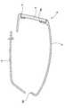
도 3은 그 저면도이고,
도 4는 도 1의 선 A-A를 따라 취한 헤드의 단면도이고,
도 5는 도 1에 도시된 헤드의 분해 사시도이고,
도 6은 본 발명의 다른 실시예에 따른 골프 클럽 헤드의 분해 사시도이고,
도 7은 종래의 골프 클럽 헤드의 단면도이다.1 is a plan view of a reference state of a golf club head according to an embodiment of the present invention,
Fig. 2 is a front view of Fig. 1,
3 is a bottom view thereof,
4 is a cross-sectional view of the head taken along line AA of FIG. 1,
FIG. 5 is an exploded perspective view of the head shown in FIG. 1,
6 is an exploded perspective view of a golf club head according to another embodiment of the present invention,
7 is a cross-sectional view of a conventional golf club head.
이하에서, 본 발명의 실시예를 첨부 도면을 참고로 하여 상세하게 설명한다.Hereinafter, embodiments of the present invention will be described in detail with reference to the accompanying drawings.
도 1 내지 도 4에 있어서, 본 발명의 실시예에 따른 골프 클럽 헤드(1)는 기준 상태로 도시되어 있다.1 to 4, a
여기서, 기준 상태란, 클럽 샤프트(도시 생략)의 축선(CL)이 헤드에 대하여 특정된 라이각(α)으로 경사진 상태로 수직면(VP) 내에 배치되고, 스위트 스폿(SS)에서의 클럽 페이스(2A)가 헤드에 대하여 특정된 로프트각(β)을 형성하도록 수평면(P) 상에 놓여 있는 클럽 헤드의 상태를 의미한다. 클럽 헤드 단독의 경우에는, 클럽 샤프트의 축선(CL) 대신에, 후술하는 샤프트 삽입 구멍(7a)의 중심선이 사용된다. 로프트각(β)은 0°보다 크다. 클럽 페이스 각도는 제로로 설정된다.Herein, the reference state is a state in which the axis CL of the club shaft (not shown) is disposed in the vertical plane VP in a state inclined at a lie angle? Specified with respect to the head, and the
상세한 설명 및 청구범위를 포함한 본 명세서에 있어서, 클럽 헤드와 관련한 치수, 위치 및 방향 등은, 달리 언급하지 않는 한은 클럽 헤드의 기준 상태에서의 것을 의미한다.In the present specification, including the detailed description and the claims, the dimensions, position, direction and the like with respect to the club head means in the reference state of the club head unless otherwise stated.
후술하는 헤드의 전후 방향(TH)은, 수평면(HP)에 투영된 직선(N)과 평행한 방향을 의미하고, 여기서 직선(N)은 클럽 페이스(2A)에 대하여 수직을 이루고, 클럽 헤드의 무게 중심(G)을 통과한다.The forward and backward directions TH of the head to be described later mean directions parallel to the straight line N projected on the horizontal plane HP where the straight line N is perpendicular to the
상기 스위트 스폿(SS)은 클럽 페이스(2A)와 직선(N)의 교점에 대응한다.The sweet spot SS corresponds to the intersection of the straight line N and the
상기 힐 앤드 토우 방향은, 수평면(HP)과 평행하고 전후 방향(TH)에 수직한 방향이다.The heel and toe direction is parallel to the horizontal plane HP and perpendicular to the fore and aft direction TH.
도면에 있어서, 본 발명에 따른 클럽 헤드(1)는, 그 전면(前面)이 볼을 타격하는 클럽 페이스(2A)를 이루는 페이스부(3)와, 페이스부(3)의 상부 가장자리(2a)에 연결되며 클럽 헤드의 상면을 이루는 크라운부(4)와, 페이스부(3)의 하부 가장자리(2b)에 연결되며 클럽 헤드의 바닥면을 이루는 솔부(5)와, 상기 크라운부(4)와 솔부(5) 사이를 연결하고 상기 페이스부(3)의 토우측 가장자리(2c)로부터 헤드의 백페이스(2B)를 통하여 힐측 가장자리(2d)까지 연장되는 사이드부(6)와, 상기 크라운부(4)의 힐측에 위치되고 또한 클럽 샤프트(도시 생략)의 선단이 삽입되는 샤프트 삽입 구멍(7a)을 갖는 관형의 호젤부(7)를 구비한다. 또한, 클럽 헤드(1)는 얇은 벽으로 둘러싸인 중공부(i)를 갖는 중공 구조로 되어 있다.In the figure, the
본 발명은 우드 타입의 골프 클럽 헤드에 적절하게 적용된다. 여기서, "우드 타입"이라는 용어는, 적어도 드라이버(#1 우드), 브러시(#2 우드), 스푼(#3 우드), 버피(#4 우드) 및 크릭(#5 우드)과, 이들과 유사한 형상을 갖는 다른 클럽 헤드를 의미한다.The present invention is suitably applied to a wood type golf club head. Here, the term "wood type" means at least a driver (# 1 wood), a brush (# 2 wood), a spoon (# 3 wood), a buff (# 4 wood) Means another club head having a shape.
클럽 헤드(1)의 체적(V)은 특별히 제한되지 않지만, 골프 스윙의 용이성의 관점에서, 체적(V)은 120 cc 이상, 보다 바람직하게는 130 cc 이상이다. 그러나 클럽 헤드(1)의 체적이 지나치게 크게 되면, 클럽 헤드의 중량이 증가하여, 스윙 밸런스의 악화 및 골프 규칙 위반 등의 문제가 생긴다. 따라서 체적(V)은 460 cc 이하가 바람직하다.The volume V of the
클럽 헤드(1)의 질량은 바람직하게는 170g 이상이고, 보다 바람직하게는 180g 이상이며, 또한 바람직하게는 240g 이하이고, 보다 바람직하게는 230g 이하이다. 질량이 170g 미만이면, 클럽 헤드의 운동 에너지가 작아져, 비거리의 향상을 기대하기 어려운 경향이 있다. 이와 달리, 240g을 넘으면, 스윙이 곤란하여, 타구의 방향 안정성 및 비거리가 악화되는 경향이 있다.The mass of the
도 5에 도시된 바와 같이, 본 실시예의 클럽 헤드(1)는, 페이스부(3)에서 개구되는 페이스 개구부(Of)와 솔부측에서 개구되는 솔 개구부(Os)가 각각 독립적으로 마련된 본체 부재(1A)와, 상기 페이스 개구부(Of)를 덮는 페이스 부재(1B)와, 상기 솔 개구부(Os)를 덮는 솔 부재(1C)를 포함한다.5, the
본 실시예에 있어서의 본체 부재(1A), 페이스 부재(1B) 및 솔 부재(1C)는 각각의 위치에 적합한 서로 상이한 금속 재료로 제조된다.The
본체 부재의 비중(D1)은 페이스 부재의 비중(D2)보다는 크지만, 솔 부재의 비중(D3)보다는 작다(D3>D1>D2). 이로써, 클럽 헤드(1)의 무게 중심이 낮아지고 무게 중심의 깊이가 증가하여, 타구의 방향 안정성 및 비거리를 향상시킬 수 있다.The specific gravity D1 of the body member is larger than the specific gravity D2 of the face member but smaller than the specific gravity D3 of the bristle member (D3> D1> D2). Thereby, the center of gravity of the
페이스 부재(1B)는 브레이징 또는 납땜에 의해 본체 부재에 고착되어 페이스 개구부(Of)를 폐쇄한다. 페이스 부재(1B)는 클럽 페이스의 스위트 스폿(SS)을 포함한다. 페이스 부재(1B)가 클럽 페이스(2A)의 면적의 적어도 60%를 점유하는 것이 바람직하다.The
페이스 부재(1B)의 금속 재료로서는, 비강도(specific strength)가 큰 Ti-15V-6Cr-4Al, Ti-6Al-4V 등의 티탄 합금이 바람직하게 사용된다.As the metal material of the
본 실시예에 있어서는, 도 4에 도시된 바와 같이, 페이스 부재(1B)는 두꺼운 중앙부(1Ba)와 두꺼운 중앙부(1Ba)를 에워싸는 얇은 둘레부(1Bb)를 갖는 판형의 부재이다. 페이스부(3)는 페이스 부재(1B)와, 페이스 개구부(Of)를 둘러싸는 페이스 가장자리부(8)에 의해 형성된다.In this embodiment, as shown in Fig. 4, the
페이스부(3)의 내구성 및 클럽 헤드의 저중량화를 밸런스 좋게 하기 위해서는, 두꺼운 중앙부(1Ba)의 두께(t1)는 바람직하게는 1.5 ㎜ 이상이면서 4.0 ㎜ 이하인 것이 바람직하다. 본 명세서에 있어서, 두께라고 하는 것은, 클럽 페이스(2) 또는 솔부(5)의 표면에 형성된 홈, 펀치 마크 등의 오목부를 매립한 상태에서 측정한 것이다.The thickness t1 of the thick central portion 1Ba is preferably 1.5 mm or more and 4.0 mm or less in order to balance the durability of the
상기 효과를 효율적으로 발휘하기 위해서, 헤드의 외면에 투영된 페이스 부재(1B)의 면적(본 실시예에 있어서, 판형의 페이스 부재의 전면(前面)의 면적과 동일)은 바람직하게는 16 ㎠ 이상, 보다 바람직하게는 17 ㎠ 이상, 또한 바람직하게는 50 ㎠ 이하, 보다 바람직하게는 48 ㎠ 이하로 설정되는 것이 바람직하다.In order to effectively exhibit the above effect, the area of the
본 실시예에 있어서의 본체 부재(1A)는 크라운부(4), 호젤부(7) 및 페이스 가장자리부(8)를 구비한다.The
본 실시예에 있어서의 페이스 개구부(Of)는 페이스부(3) 내에 형성된다. 이로써, 페이스 가장자리부(8)는 페이스 개구부(Of)의 둘레에 환형으로 연속해서 형성된다.In the present embodiment, the face opening portion Of is formed in the
페이스 개구부(Of)의 형상은 특별히 한정되지 않지만, 본 실시예에서와 같이 페이스부(3)의 가장자리(2a-2d)의 윤곽과 거의 평행한 원만한 윤곽을 갖는 형상이 바람직하다.The shape of the face opening portion Of is not particularly limited, but a shape having a smooth outline roughly parallel to the outline of the
페이스 가장자리부(8)는 실질적으로 페이스부의 전면의 둘레부를 형성하는 메인부(8a)와, 메인부(8a)의 외면으로부터 단계적으로 오목하게 되어 페이스 부재(1B)의 내면(1Bi)의 둘레부를 지지하는 수용부(8b)를 구비한다. 본 예에 있어서의 수용부(8b)는 페이스 개구부(Of)의 둘레에 환형으로 연속해서 형성된다.The
도 3 내지 도 5에 도시된 바와 같이, 솔 개구부(Os)는 하부 가장자리(2b)로부터 후방으로 이격되어 있고 솔부(5)로부터 사이드부(6)에 걸쳐 연장된다. 그러나 솔 개구부(Os)가 그러한 형상으로 한정되는 것은 아니다. 솔부(5) 내에 형성되는 솔 개구부(Os)를 채용할 수도 있다.3 to 5, the sole opening Os is spaced rearwardly from the
본체 부재(1A)는, 솔 개구부(Os)의 내주면(또는 전방 가장자리)의 전방부로부터 페이스부를 향해 연장되는 부분을 형성하는 전방 가장자리부(9)[이하에서, 솔 개구부의 전방 가장자리부(9)로 지칭함]와, 솔 개구부의 전방 가장자리부(9)와 페이스부(3) 사이의 부분을 형성하고 솔 개구부의 전방 가장자리부(9)보다 두꺼운 열 차단부(10)를 더 구비한다.The
솔 개구부의 전방 가장자리부(9)의 두께(tA)는 0.5 ㎜ 이상이면서 2.5 ㎜ 미만일 필요가 있다. 두께(tA)가 0.5 ㎜ 미만이면, 클럽 헤드(1)의 내구성이 악화된다. 두께(tA)가 2.5 ㎜ 이상이면, 용접 시간이 증가하여, 용접 중의 열이 페이스 부재(1B)의 필러 금속에 전달되어, 접합 강도가 저하된다. 이러한 이유로, 솔 개구부의 전방 가장자리부(9)의 두께(tA)는, 바람직하게는 0.7 ㎜ 이상, 보다 바람직하게는 0.9 ㎜ 이상이고, 또한 바람직하게는 2.3 ㎜ 이하, 보다 바람직하게는 2.1 ㎜ 이하이다.The thickness tA of the
또한, 열 차단부(10)의 두께(tB)는 2.5 ㎜ 내지 10.0 ㎜의 범위로 설정될 필요가 있다. 두께(tB)가 2.5 ㎜ 미만이면, 클럽 헤드(1)의 강도가 저하되고, 열 차단부(10)의 열용량이 감소하며, 용접 중의 열이 페이스 부재(1B)의 필러 금속에 용이하게 전달된다. 두께(tB)가 10.0 ㎜를 초과하면, 본체 부재(1A)를 가공하기가 어렵게 되어, 생산성이 악화된다. 또한, 클럽 헤드(1)의 질량이 증가하고 스윙이 어렵게 된다. 이러한 이유로, 열 차단부(10)의 두께(tB)는, 바람직하게는 2.7 ㎜ 이상, 보다 바람직하게는 2.9 ㎜ 이상이고, 또한 바람직하게는 8.0 ㎜ 이하, 보다 바람직하게는 7.7 ㎜ 이하이다.In addition, the thickness tB of the
상기 효과를 더욱 효율적으로 발휘하기 위해서, 열 차단부(10)의 두께(tB)는 바람직하게는, 솔 개구부의 전방 가장자리부(9)의 두께(tA)의 1.2배 이상, 보다 바람직하게는 1.7배 이상이고, 또한 바람직하게는 8.0배 이하, 보다 바람직하게는 6.0배 이하이다.The thickness tB of the
본 실시예에 있어서의 솔 개구부의 전방 가장자리부(9)는 실질적으로 동일한 폭(Wa)으로 힐 앤드 토우 방향으로 연장되는 영역으로서 형성된다. 이러한 얇은 솔 개구부의 전방 가장자리부(9)의 폭(Wa)이 증가하면, 클럽 헤드(1)의 강도가 저하되어, 용접 중의 열이 페이스부에 보다 많이 전달되어 필러 금속에 영향을 끼칠 우려가 있다. 이와 달리 폭(Wa)이 감소하면, 열 차단부(10)가 확장되어, 클럽 헤드의 질량이 증가하므로, 스윙이 곤란하게 될 우려가 있다. 이러한 이유로, 솔 개구부의 전방 가장자리부(9)의 길이 방향에 대하여 수직인 방향으로 측정한[또는 솔 개구부의 전방 가장자리에 수직인 방향으로 측정한] 폭(Wa)은 바람직하게는, 5.0 ㎜ 이상, 보다 바람직하게는 6.0 ㎜ 이상이고, 또한 바람직하게는 10.0 ㎜ 이하, 보다 바람직하게는 9.0 ㎜ 이하의 범위로 설정되는 것이 바람직하다.The
상기 효과를 효율적으로 발휘하기 위해서, 힐 앤드 토우 방향(IH)으로 솔 개구부의 전방 가장자리부(9)의 길이(L2)는 힐 앤드 토우 방향(IH)에 있어서의 솔 부재(1C)의 최대 폭(Ls)의 70% 내지 90%의 범위로 설정되는 것이 바람직하다.In order to effectively exhibit the above effect, the length L2 of the
상기 솔 개구부의 전방 가장자리부(9)는, 동일 두께를 갖는 균등 두께 부분(9A)과, 균등 두께 부분(9A)과 열 차단부(10) 사이에 형성되고 두께가 상기 동일 두께로부터 열 차단부(10)의 두께까지 점진적으로 증가하는 점증부(9B)로 구성되는 것이 바람직하다. 여기서, 솔 개구부의 전방 가장자리부(9)의 두께(tA)는 폭(Wa)에 걸친 평균 두께이다. 이러한 점증부(9B)는 비교적 두께가 얇은 균등 두께 부분(9A)에 대한 충격을 저감시키고, 강도 및 내구성을 증가시키는 작용을 한다.The
본체 부재(1A)를 형성하는 금속 재료로서는, 페이스 부재(1B)보다 비중이 큰 재료를 사용하는 것이 바람직하다. 예컨대, 스테인리스강, 마레이징강, 티탄 합금 등을 바람직하게 사용할 수 있다.As the metallic material forming the
본체 부재(1A)는 단조 또는 주조 기술에 의해 제조될 수도 있고, 압연 금속(들)으로 형성된 2회 이상의 굽힘 가공된 가공품을 함께 접합하는 기술에 의해 제조될 수도 있다. 생산성을 향상시키기 위해서는, 모든 부품이 일체로 형성된 하나의 주조품으로서 형성하는 것이 바람직하다.The
솔 부재(1C) 및 본체 부재(1A)의 용접 중에 열이 페이스 부재(1B)에 전달되는 것을 억제하고, 클럽 헤드의 무게 중심을 낮추며, 클럽 헤드의 과도한 질량 증가를 피하기 위하여, 클럽 헤드(1)의 리딩 에지(Le)(기준 상태의 페이스부의 전단 위치)로부터 솔 개구부(Os)까지의 전후 방향(TH)으로 측정한 최단 거리(L1)[즉, 리딩 에지(Le)와 솔 부재의 전방 가장자리부(12)의 전단 사이의 전후 방향의 거리]는, 리딩 에지(Le)와 클럽 헤드의 최후 지점 사이의 전후 방향(TH)으로 측정한 최대 길이인 클럽 헤드 길이(La)의 바람직하게는 15% 이상, 보다 바람직하게는 18% 이상이고, 또한 바람직하게는 40% 이하, 보다 바람직하게는 35% 이하의 범위로 설정된다.In order to prevent the heat from being transferred to the
본 실시예에 있어서의 솔 부재(1C)는, 후방 상부로부터 전방 하부로 비스듬하게 잘려진 컵 모양과 유사한 반컵(semi-cup) 형상을 갖는다. 솔 부재(1C)는 브레이징/땜납 또는 용접(본 실시예에서는, 맞대기 용접)에 의해 본체 부재(1A)에 고착되어 솔 개구부(Os)를 폐쇄한다. 다양한 용접 기술을 채용할 수 있지만, 열 영향 영역을 줄일 수 있다는 관점에서, 레이저 용접이 바람직하다.The
솔 부재(1C)를 형성하는 금속 재료로서는, 본체 부재(1A)보다 비중이 큰 재료를 사용하여 클럽 헤드(1)의 무게 중심을 낮추고 있다. 바람직하게는, 텅스텐 합금, 예컨대 W-Ni 합금 등이 이용된다.As the metal material forming the
도 5에 도시된 바와 같이, 솔 부재(1C)는, 클럽 페이스측을 형성하고 솔 개구부의 전방 가장자리부(9)에 연결된 전방 가장자리부(12)[이하에서는, 솔 부재의 전방 가장자리부(12)라고 칭함]와, 솔 부재의 전방 가장자리부(12)로부터 후방으로 연장되는 백 페이스측을 형성하고 솔 부재의 전방 가장자리부(12)보다 두꺼운 솔 보강부(13)를 구비한다.5, the
솔 부재의 전방 가장자리부(12)의 두께(tC)를 0.5 ㎜ 이상 2.5 ㎜ 미만으로 할 필요가 있다. 두께(tC)가 0.5 ㎜ 미만이면, 클럽 헤드(1)의 내구성이 저하된다. 두께(tC)가 2.5 ㎜ 이상이면, 용접 시간이 증가하여, 용접 중의 열이 페이스 부재(1B)의 필러 금속에 전달되므로, 접합 강도가 저하된다. 이러한 이유로, 솔 부재의 전방 가장자리부(12)의 두께(tC)는, 바람직하게는 0.7 ㎜ 이상, 보다 바람직하게는 0.9 ㎜ 이상으로, 또한 바람직하게는 2.3 ㎜ 이하, 보다 바람직하게는 2.1 ㎜ 이하의 범위로 설정된다.It is necessary to set the thickness tC of the
또한, 솔 보강부(13)의 두께(tD)를 2.5 ㎜ 내지 10.0 ㎜의 범위로 설정할 필요가 있다. 두께(tD)가 2.5 ㎜ 미만이면, 클럽 헤드(1)의 강도가 저하될 뿐 아니라, 무게 중심을 낮추기 어렵고 또한 무게 중심의 깊이를 크게 하기 어렵게 된다. 두께(tD)가 10.0 ㎜를 초과하면, 두께가 과도하게 증가하여, 단조 변형이 커지기 쉬워, 생산성이 저하된다. 이러한 이유로, 솔 보강부(13)의 두께(tD)는, 바람직하게는 2.7 ㎜ 이상, 보다 바람직하게는 2.9 ㎜ 이상으로, 또한 바람직하게는 8.0 ㎜ 이하, 보다 바람직하게는 7.7 ㎜ 이하의 범위로 설정된다.Further, it is necessary to set the thickness tD of the sole reinforcing
클럽 헤드의 저면에서 보았을 때, 상기 솔 부재의 전방 가장자리부(12)의 면적(Sf)은 솔 부재(1C)의 면적(S2)의 10% 내지 30%의 범위로 설정되는 것이 바람직하다. 이러한 솔 부재의 전방 가장자리부(12)는, 용접 시간의 단축과 클럽 페이스의 강도를 밸런스 좋게 확보할 수 있게 한다.It is preferable that the area Sf of the
상기 효과를 발휘하기 위해서, 솔 부재의 전방 가장자리부(12)의 길이 방향에 수직인 방향으로 측정한(또는 솔 부재의 전방 가장자리에 수직인 방향으로 측정한) 솔 부재의 전방 가장자리부(12)의 폭(Wb)은, 클럽 헤드 길이(La)의 6.0% 이상, 보다 바람직하게는 7.0% 이상으로, 또한 15.0% 이하, 보다 바람직하게는 12.0% 이하의 범위로 설정되는 것이 바람직하다.The
솔 부재(1C)의 면적(S2)은 특별히 한정되지 않지만, 클럽 헤드의 무게 중심을 낮추면서 클럽 헤드의 질량의 과도한 증가를 밸런스 좋게 회피한다는 관점에서, 솔 부재(1C)의 면적(S2)은 바람직하게는 40 ㎠ 이상, 보다 바람직하게는 43 ㎠ 이상으로, 또한 바람직하게는 60 ㎠ 이하, 보다 바람직하게는 55 ㎠ 이하의 범위로 설정하는 것이 바람직하다.The area S2 of the
도 3에 도시된 바와 같이, 본 실시예에 있어서의 솔 부재의 전방 가장자리부(12)는, 솔 부재(1C)의 전방 가장자리를 따라 일정한 폭으로 연장되는 영역으로 형성된다. 그러나 솔 부재의 전방 가장자리부(12)가 그러한 형상으로 한정되는 것은 아니며, 다양한 형상을 채용할 수 있다.As shown in Fig. 3, the
이하에서는, 전술한 바와 같이 구성된 클럽 헤드(1)를 제조하는 제조 방법을 설명한다.Hereinafter, a manufacturing method for manufacturing the
본 실시예에 있어서는, 먼저, 본체 부재(1A), 페이스 부재(1B) 및 솔 부재(1C)를 준비하는 공정을 실행한다. 각 부재(1A 내지 1C)는 주조, 단조, 프레스 성형 등의 다양한 방법으로 제조될 수 있다.In this embodiment, first, a step of preparing the
다음으로, 페이스 부재(1B)를 브레이징/납땜에 의해 본체 부재(1A)에 고착하여 페이스 개구부(Of)를 폐쇄하는 페이스 부재 고착 공정을 실행한다.Next, a face member fixing step for fixing the
페이스 부재 고착 공정에 있어서는, 페이스 부재(1B)와 본체 부재(1A)의 접합부에 대응하는 위치에서 클럽 헤드의 내측 및 외측에, 예컨대 페이스트 형태의 필러 금속을 제공하고 가열한다. 이에 의해, 필러 금속이 페이스 부재(1B)와 본체 부재(1A) 사이의 공간으로 흘러 들어가 고화되어, 페이스 부재(1B)를 본체 부재(1A)에 고착한다. 솔 개구부(Os)를 활용함으로써, 필러 금속을 클럽 헤드(1)의 내측에 용이하게 제공할 수 있다.In the face member fixing step, for example, a paste type filler metal is provided and heated at the positions corresponding to the joining portions of the
페이스 부재 고착 공정 후에는, 솔 부재(1C)를 본체 부재(1A)에 용접하여 솔 개구부(Os)를 폐쇄하는 솔 부재 고착 공정을 실행한다. 이 공정에서는, 예컨대 이산화탄소 가스의 레이저를 이용한 레이저 용접 등과 같이 특히 밀도가 높은 에너지를 공급할 수 있는 용접 방법을 채용하는 것이 바람직하다. 이로써, 단시간 내에 용접이 가능하게 되어 필러 금속의 열 변형을 억제할 수 있으므로, 페이스부의 내구성이 향상된다.After the face member affixing step, a sol-member securing step of closing the sol opening Os by welding the sol 1 (1C) to the
전술한 바와 같이, 본 실시예에 있어서의 클럽 헤드(1)가 제작된다.As described above, the
바람직한 실시예를 설명하였지만, 당업자는 이하의 청구범위에서 기술하는 바와 같은 본 발명의 개념의 범위 내에서 다양한 변형이 있을 수 있다는 것을 이해할 것이다.While a preferred embodiment has been described, it will be understood by those skilled in the art that various modifications may be made within the scope of the inventive concept as described in the following claims.
예컨대, 도 6에 도시된 바와 같이, 클럽 헤드(1)는, 전술한 페이스 개구부(Of) 및 솔 개구부(Os)와 크라운부측에서 개구된 추가의 크라운 개구부(Oc)가 각각 독립적으로 마련된 본체 부재(1A)와, 페이스 개구부(Of)를 폐쇄하는 페이스 부재(1B)와, 솔 개구부(Os)를 폐쇄하는 솔 부재(1C)와, 크라운 개구부(Oc)를 폐쇄하는 크라운 부재(1D)를 포함하는 중공 구조를 가질 수도 있다. 이러한 클럽 헤드(1)에 있어서는, 솔 개구부(Os) 및 크라운 개구부(Oc)를 활용하여 페이스 부재(1B)를 브레이징/납땜할 수 있으므로, 클럽 헤드(1)를 더욱 효과적으로 제조할 수 있다. 예컨대, 크라운 부재(1D)는 섬유 보강 플라스틱으로 이루어진 얇은 판형의 부재로서 형성될 수 있다.6, the
비교 테스트Comparison test
본 발명의 효과를 확인하기 위하여, 도 1 내지 도 5에 도시된 구조를 기초로 하여 우드 타입의 골프 클럽 헤드(크릭, 체적: 155cc, 로프트각: 18°, 라이각: 59°)를 시험 제작하고, 클럽 페이스의 내구성을 테스트하였다.In order to confirm the effect of the present invention, a wood type golf club head (creek, volume: 155 cc, loft angle: 18 degrees, lie angle: 59 degrees) was manufactured on the basis of the structure shown in Figs. 1 to 5 , And tested the durability of the clubface.
헤드의 사양은 표 1에 나타낸 것을 제외하고는 동일하게 하였다.The specifications of the head were the same except for those shown in Table 1.
공통적인 주요 사항은 다음과 같다.Common key points are as follows.
본체 부재: 스테인리스강 (비중 7.8)Body member: Stainless steel (specific gravity 7.8)
솔 부재: W-Ni 합금 (비중 8.25)Brass member: W-Ni alloy (specific gravity 8.25)
페이스 부재: Ti 합금 (비중 4.45)Face member: Ti alloy (specific gravity: 4.45)
페이스 부재의 평균 두께: 2.5 ㎜Average thickness of face member: 2.5 mm
<내구성 테스트><Durability test>
클럽 헤드를 동일한 FRP 샤프트(SRI Sports Limited 제조의 "MP600", 플렉스 R)에 장착하여 42 인치의 #5 우드 클럽을 제작하였다. 각 클럽을 Miyamae Co., Ltd. 제조의 스윙 로봇에 장착하고, 47 m/s의 헤드 속도로 클럽 페이스의 스위트 스폿으로 골프공을 반복적으로 타격하였다. 페이스 부재와 본체 부재의 접합부에 어떠한 손상도 야기하지 않으면서 달성되는 타격 횟수를 카운트하였다. 그 결과를 표 1에 나타낸다. 합격 범위는 3000회 이상이다.The club head was mounted on the same FRP shaft ("MP600" manufactured by SRI Sports Limited, Flex R) to produce a 42-
<클럽 헤드의 질량 측정><Mass measurement of club head>
각 클럽 헤드의 질량을 측정하였다. 그 결과를 표 1에 나타낸다. 질량이 과도하게 크면, 클럽을 스윙하기가 곤란하므로, 바람직하지 않다.The mass of each club head was measured. The results are shown in Table 1. If the mass is excessively large, it is not preferable since it is difficult to swing the club.

테스트 결과로부터, 본 발명에 따른 클럽 헤드는, 비교예의 클럽 헤드와 비교하여, 클럽 헤드의 질량을 과도하게 증가시키지 않으면서 내구성이 향상되는 것으로 확인되었다.From the test results, it was confirmed that the club head according to the present invention has improved durability without excessively increasing the mass of the club head, as compared with the club head of the comparative example.
1 골프 클럽 헤드
1A 본체 부재
1B 페이스 부재
1C 솔 부재
2A 클럽 페이스
2B 백 페이스
3 페이스부
5 솔부
Of 페이스 개구부
Os 솔 개구부
9 솔 개구부의 전방 가장자리부
10 열 차단부
12 솔 부재의 전방 가장자리부
13 솔 보강부1 golf club head
1A body member
1B face member
1C brush member
2A club face
2B Backface
3 face portion
5 sole
Offace opening
Os Sol opening
9 The front edge portion of the sole opening
10 heat block
The front end portion of the 12-
13 Brush reinforcement
Claims (14)
Translated fromKorean상기 페이스부의 하부 가장자리로 연장되고 헤드의 바닥면을 형성하는 솔부
를 구비하는 중공 구조의 골프 클럽 헤드로서,
상기 골프 클럽 헤드는, 페이스부에서 개구되는 페이스 개구부와 상기 솔부에서 개구되는 솔 개구부가 각각 독립적으로 마련된 본체 부재와,
상기 본체 부재에 브레이징 또는 납땜에 의해 고착되어 상기 페이스 개구부를 폐쇄하는 페이스 부재와,
상기 본체 부재에 브레이징, 납땜 또는 용접에 의해 고착되어 상기 솔 개구부를 폐쇄하는 솔 부재를 포함하고,
상기 본체 부재는, 상기 솔 개구부의 전방 가장자리로부터 페이스부를 향해 연장되는 부분을 형성하는 솔 개구부의 전방 가장자리부와, 솔 개구부의 전방 가장자리부와 페이스부 사이의 부분을 형성하고 상기 솔 개구부의 전방 가장자리부보다 두꺼운 열 차단부를 구비하고,
상기 솔 부재는, 상기 솔 개구부의 전방 가장자리부에 접속되고 솔 부재의 페이스측 부분을 형성하는 솔 부재의 전방 가장자리부와, 상기 솔 부재의 전방 가장자리부로부터 헤드의 이면측을 향해서 연장되는 부분을 형성하고 솔 부재의 전방 가장자리부보다 두꺼운 솔 보강부를 구비하고,
상기 솔 부재의 전방 가장자리부의 두께와 상기 솔 개구부의 전방 가장자리부의 두께는 0.5 ㎜ 이상 2.5 ㎜ 미만이며,
상기 솔 보강부의 두께 및 상기 열 차단부의 두께는 2.5 ㎜ 내지 10.0 ㎜인 것인 골프 클럽 헤드.A club face hitting the ball is provided with a face portion provided on the front face thereof,
A head portion extending to a lower edge of the face portion and forming a bottom surface of the head,
Wherein the hollow golf club head comprises:
The golf club head includes a body member having a face opening portion opened at the face portion and a sole opening portion opened at the sole portion,
A face member fixed to the body member by brazing or brazing to close the face opening,
And a bristle member secured to the body member by brazing, brazing or welding to close the bristle opening,
Wherein the body member includes a front edge portion of a sole opening portion forming a portion extending from the front edge of the sole opening portion toward the face portion and a front edge portion of the sole opening portion and a front portion of the sole opening portion, And a heat shielding portion thicker than the heat shielding portion,
Wherein the bristle member has a front edge portion of a bristle member connected to the front edge portion of the bristle mouth portion and forming a face side portion of the bristle member and a portion extending from the front edge portion of the bristle member toward the back side of the bristle And a bristle reinforcing portion thicker than the front edge portion of the bristle member,
The thickness of the front edge portion of the bristle member and the thickness of the front edge portion of the bristle mouth portion are not less than 0.5 mm and less than 2.5 mm,
Wherein the thickness of the brush reinforcing portion and the thickness of the heat shielding portion are 2.5 mm to 10.0 mm.
상기 솔 개구부의 전방 가장자리부, 상기 솔 부재의 전방 가장자리부 및 상기 솔 보강부도 상기 원호를 따라 만곡되어 있는 것인 골프 클럽 헤드.13. The apparatus of claim 12, wherein the front edge of the sole opening is curved to draw a convex arc toward the face portion,
Wherein the front edge portion of the sole opening portion, the front edge portion of the bristle member, and the sole reinforcement portion are also curved along the arc.
Applications Claiming Priority (2)
| Application Number | Priority Date | Filing Date | Title |
|---|---|---|---|
| JP2011119507AJP5174214B2 (en) | 2011-05-27 | 2011-05-27 | Golf club head |
| JPJP-P-2011-119507 | 2011-05-27 |
Publications (2)
| Publication Number | Publication Date |
|---|---|
| KR20120132381A KR20120132381A (en) | 2012-12-05 |
| KR101906600B1true KR101906600B1 (en) | 2018-10-10 |
Family
ID=47193465
Family Applications (1)
| Application Number | Title | Priority Date | Filing Date |
|---|---|---|---|
| KR1020120055165AActiveKR101906600B1 (en) | 2011-05-27 | 2012-05-24 | Golf club head |
Country Status (4)
| Country | Link |
|---|---|
| US (1) | US8647217B2 (en) |
| JP (1) | JP5174214B2 (en) |
| KR (1) | KR101906600B1 (en) |
| CN (1) | CN102794004B (en) |
Families Citing this family (36)
| Publication number | Priority date | Publication date | Assignee | Title |
|---|---|---|---|---|
| US9662545B2 (en)* | 2002-11-08 | 2017-05-30 | Taylor Made Golf Company, Inc. | Golf club with coefficient of restitution feature |
| US10080934B2 (en) | 2002-11-08 | 2018-09-25 | Taylor Made Golf Company, Inc. | Golf club with coefficient of restitution feature |
| US9358430B2 (en) | 2010-12-31 | 2016-06-07 | Taylor Made Golf Company, Inc. | High loft, low center-of-gravity golf club heads |
| JP6077819B2 (en)* | 2012-10-17 | 2017-02-08 | ダンロップスポーツ株式会社 | Golf club head |
| JP6181922B2 (en)* | 2012-12-03 | 2017-08-16 | ダンロップスポーツ株式会社 | Golf club head |
| JP6341701B2 (en) | 2013-03-15 | 2018-06-13 | テイラー メイド ゴルフ カンパニー, インコーポレーテッド | Golf club having restitution coefficient mechanism |
| JP6295459B2 (en)* | 2013-08-13 | 2018-03-20 | 住友ゴム工業株式会社 | Iron type golf club head |
| JP6295461B2 (en)* | 2014-03-24 | 2018-03-20 | 住友ゴム工業株式会社 | Golf club head |
| US10918919B2 (en) | 2014-05-15 | 2021-02-16 | Karsten Manufacturing Corporation | Club heads having reinforced club head faces and related methods |
| US10751587B2 (en) | 2014-05-15 | 2020-08-25 | Karsten Manufacturing Corporation | Club heads having reinforced club head faces and related methods |
| US10888743B2 (en)* | 2014-10-24 | 2021-01-12 | Karsten Manufacturing Corporation | Golf club heads with energy storage characteristics |
| US12102892B2 (en) | 2014-05-15 | 2024-10-01 | Karsten Manufacturing Corporation | Club heads having reinforced club head faces and related methods |
| US10258843B2 (en) | 2014-05-15 | 2019-04-16 | Karsten Manufacturing Corporation | Club heads having reinforced club head faces and related methods |
| US10150016B2 (en)* | 2014-07-22 | 2018-12-11 | Taylor Made Golf Company, Inc. | Golf club with modifiable sole and crown features adjacent to leading edge |
| US20190160347A1 (en) | 2014-10-24 | 2019-05-30 | Karsten Manufacturing Corporation | Golf Club Heads with Energy Storage Characteristics |
| US11185747B2 (en) | 2014-10-24 | 2021-11-30 | Karsten Manufacturing Corporation | Golf club head with open back cavity |
| US11819740B2 (en) | 2014-10-24 | 2023-11-21 | Karsten Manufacturing Corporation | Golf club heads with energy storage characteristics |
| TWI636812B (en) | 2014-10-24 | 2018-10-01 | 卡斯登製造公司 | Golf club head with energy storage characteristics and manufacturing method thereof |
| US11130025B2 (en) | 2014-10-24 | 2021-09-28 | Karsten Manufacturing Corporation | Golf club heads with energy storage features |
| US11027177B2 (en) | 2014-10-24 | 2021-06-08 | Karsten Manufacturing Corporation | Golf club heads with energy storage characteristics |
| US11278772B2 (en)* | 2014-10-24 | 2022-03-22 | Karsten Manufacturing Corporation | Golf club heads with energy storage characteristics |
| JP6417213B2 (en)* | 2014-12-25 | 2018-10-31 | 住友ゴム工業株式会社 | Golf club head |
| US20160271462A1 (en)* | 2015-03-17 | 2016-09-22 | Dean L. Knuth | Golf club with low and rearward center of gravity |
| JP5848840B1 (en)* | 2015-06-05 | 2016-01-27 | ダンロップスポーツ株式会社 | Golf club head |
| JP5844934B1 (en)* | 2015-06-05 | 2016-01-20 | ダンロップスポーツ株式会社 | Golf club head |
| US10612109B2 (en)* | 2015-11-19 | 2020-04-07 | Karsten Manufacturing Corporation | Method of relieving stress from face plate welds of a golf club head |
| US20230166167A1 (en)* | 2016-07-26 | 2023-06-01 | Acushnet Company | Golf club having a damping element for ball speed control |
| JP2018064607A (en)* | 2016-10-17 | 2018-04-26 | グローブライド株式会社 | Method of manufacturing golf club head |
| US11618306B2 (en) | 2016-10-27 | 2023-04-04 | Nicholas J. Singer | Skeleton for truck bed and convertible top |
| JP3223387U (en)* | 2018-08-22 | 2019-10-03 | 莊繼舜 | Golf club head that can be made to order |
| TWI657849B (en)* | 2018-09-18 | 2019-05-01 | 明安國際企業股份有限公司 | Golf head |
| JP6645569B1 (en)* | 2018-12-27 | 2020-02-14 | 住友ゴム工業株式会社 | Golf club head |
| KR102431860B1 (en) | 2020-10-07 | 2022-08-10 | 이동현 | Utility golf club for approach |
| JP2023142738A (en)* | 2022-03-25 | 2023-10-05 | ヤマハ株式会社 | Wood type golf club head and wood type golf club |
| USD1040271S1 (en) | 2022-07-08 | 2024-08-27 | Karsten Manufacturing Corporation | Golf club head |
| JP2024010620A (en)* | 2022-07-12 | 2024-01-24 | 住友ゴム工業株式会社 | golf club head |
Citations (12)
| Publication number | Priority date | Publication date | Assignee | Title |
|---|---|---|---|---|
| US20010007837A1 (en) | 1998-01-30 | 2001-07-12 | Yuu Hasebe | Golf club head |
| US20040009830A1 (en) | 2002-06-04 | 2004-01-15 | Masayoshi Nishio | Golf club |
| WO2004078278A1 (en) | 2003-09-11 | 2004-09-16 | Maruman & Co., Ltd. | Golfclub head producing method |
| US20050124436A1 (en) | 2003-12-09 | 2005-06-09 | Sumitomo Rubber Industries, Ltd. | Golf club head |
| US20060287131A1 (en) | 2005-06-20 | 2006-12-21 | Sri Sports Limited | Golf club head and method for manufacturing the same |
| US20070049407A1 (en) | 2005-08-23 | 2007-03-01 | Bridgestone Sports Co., Ltd. | Golf club head |
| US20070049406A1 (en) | 2005-08-23 | 2007-03-01 | Bridgestone Sports Co., Ltd. | Golf club head |
| US20070049405A1 (en) | 2005-08-23 | 2007-03-01 | Bridgestone Sports Co., Ltd. | Golf club head |
| US20070129167A1 (en) | 2005-12-02 | 2007-06-07 | Bridgestone Sports Co., Ltd. | Golf club head |
| US20100203982A1 (en) | 2006-11-17 | 2010-08-12 | Thomas Orrin Bennett | Metal wood club |
| US20110014995A1 (en) | 2009-07-17 | 2011-01-20 | Bridgestone Sports Co., Ltd. | Golf club head |
| US20120322580A1 (en) | 2011-06-15 | 2012-12-20 | Bridgestone Sports Co., Ltd | Golf club head |
Family Cites Families (7)
| Publication number | Priority date | Publication date | Assignee | Title |
|---|---|---|---|---|
| JP2773570B2 (en)* | 1992-09-18 | 1998-07-09 | 株式会社日立製作所 | Laminated panel |
| US6319149B1 (en)* | 1998-08-06 | 2001-11-20 | Michael C. W. Lee | Golf club head |
| JP2002052100A (en) | 2000-08-10 | 2002-02-19 | Mizuno Corp | Golf club head |
| US7351163B2 (en)* | 2002-05-16 | 2008-04-01 | Bridgestone Sports Co., Ltd. | Golf club head |
| JP2004167127A (en)* | 2002-11-22 | 2004-06-17 | Mizuno Corp | Metal golf club head and golf club |
| CN200984423Y (en)* | 2006-11-07 | 2007-12-05 | 复盛股份有限公司 | golf club head construction |
| US7717807B2 (en)* | 2007-09-06 | 2010-05-18 | Callaway Golf Company | Golf club head with tungsten alloy sole applications |
- 2011
- 2011-05-27JPJP2011119507Apatent/JP5174214B2/enactiveActive
- 2012
- 2012-05-24KRKR1020120055165Apatent/KR101906600B1/enactiveActive
- 2012-05-25CNCN201210168895.0Apatent/CN102794004B/enactiveActive
- 2012-05-25USUS13/480,531patent/US8647217B2/enactiveActive
Patent Citations (12)
| Publication number | Priority date | Publication date | Assignee | Title |
|---|---|---|---|---|
| US20010007837A1 (en) | 1998-01-30 | 2001-07-12 | Yuu Hasebe | Golf club head |
| US20040009830A1 (en) | 2002-06-04 | 2004-01-15 | Masayoshi Nishio | Golf club |
| WO2004078278A1 (en) | 2003-09-11 | 2004-09-16 | Maruman & Co., Ltd. | Golfclub head producing method |
| US20050124436A1 (en) | 2003-12-09 | 2005-06-09 | Sumitomo Rubber Industries, Ltd. | Golf club head |
| US20060287131A1 (en) | 2005-06-20 | 2006-12-21 | Sri Sports Limited | Golf club head and method for manufacturing the same |
| US20070049407A1 (en) | 2005-08-23 | 2007-03-01 | Bridgestone Sports Co., Ltd. | Golf club head |
| US20070049406A1 (en) | 2005-08-23 | 2007-03-01 | Bridgestone Sports Co., Ltd. | Golf club head |
| US20070049405A1 (en) | 2005-08-23 | 2007-03-01 | Bridgestone Sports Co., Ltd. | Golf club head |
| US20070129167A1 (en) | 2005-12-02 | 2007-06-07 | Bridgestone Sports Co., Ltd. | Golf club head |
| US20100203982A1 (en) | 2006-11-17 | 2010-08-12 | Thomas Orrin Bennett | Metal wood club |
| US20110014995A1 (en) | 2009-07-17 | 2011-01-20 | Bridgestone Sports Co., Ltd. | Golf club head |
| US20120322580A1 (en) | 2011-06-15 | 2012-12-20 | Bridgestone Sports Co., Ltd | Golf club head |
Also Published As
| Publication number | Publication date |
|---|---|
| KR20120132381A (en) | 2012-12-05 |
| JP5174214B2 (en) | 2013-04-03 |
| US8647217B2 (en) | 2014-02-11 |
| JP2012245169A (en) | 2012-12-13 |
| CN102794004A (en) | 2012-11-28 |
| US20120302368A1 (en) | 2012-11-29 |
| CN102794004B (en) | 2016-09-14 |
Similar Documents
| Publication | Publication Date | Title |
|---|---|---|
| KR101906600B1 (en) | Golf club head | |
| JP7606256B2 (en) | Golf Clubs | |
| JP5989509B2 (en) | Golf club head and golf club | |
| JP4256405B2 (en) | Manufacturing method of golf club head | |
| KR102081048B1 (en) | Golf club head | |
| US7318782B2 (en) | Golf club head | |
| JP5007332B2 (en) | Golf club head, golf club, method of manufacturing golf club head, and method of manufacturing golf club | |
| JP4326562B2 (en) | Golf club head | |
| EP2646123B1 (en) | Golf club heads or other ball striking devices having distributed impact response | |
| JP5135783B2 (en) | Golf club head | |
| JP2010273804A (en) | Golf club head | |
| JP6645569B1 (en) | Golf club head | |
| US7396297B2 (en) | Golf club head | |
| KR20160083894A (en) | Club head with bounded face to body yield strength ratio and related methods | |
| JP2010029358A (en) | Golf club head | |
| JP2008093268A (en) | Golf club head | |
| JP2004041376A (en) | Golf club head | |
| JP5161518B2 (en) | Golf club head | |
| US10369428B2 (en) | Golf club head | |
| JP2018007825A (en) | Golf club head | |
| JP2007216062A (en) | Golf club head | |
| JP4988364B2 (en) | Putter head | |
| JP2020191938A (en) | Golf club head | |
| JP6077819B2 (en) | Golf club head | |
| JP2008246083A (en) | Golf club head |
Legal Events
| Date | Code | Title | Description |
|---|---|---|---|
| PA0109 | Patent application | Patent event code:PA01091R01D Comment text:Patent Application Patent event date:20120524 | |
| PG1501 | Laying open of application | ||
| A201 | Request for examination | ||
| PA0201 | Request for examination | Patent event code:PA02012R01D Patent event date:20170510 Comment text:Request for Examination of Application Patent event code:PA02011R01I Patent event date:20120524 Comment text:Patent Application | |
| E902 | Notification of reason for refusal | ||
| PE0902 | Notice of grounds for rejection | Comment text:Notification of reason for refusal Patent event date:20180402 Patent event code:PE09021S01D | |
| N231 | Notification of change of applicant | ||
| PN2301 | Change of applicant | Patent event date:20180426 Comment text:Notification of Change of Applicant Patent event code:PN23011R01D | |
| E701 | Decision to grant or registration of patent right | ||
| PE0701 | Decision of registration | Patent event code:PE07011S01D Comment text:Decision to Grant Registration Patent event date:20180702 | |
| GRNT | Written decision to grant | ||
| PR0701 | Registration of establishment | Comment text:Registration of Establishment Patent event date:20181002 Patent event code:PR07011E01D | |
| PR1002 | Payment of registration fee | Payment date:20181002 End annual number:3 Start annual number:1 | |
| PG1601 | Publication of registration | ||
| PR1001 | Payment of annual fee | Payment date:20210917 Start annual number:4 End annual number:4 | |
| PR1001 | Payment of annual fee | Payment date:20230919 Start annual number:6 End annual number:6 |