KR101904030B1 - Implant components and methods - Google Patents
Implant components and methodsDownload PDFInfo
- Publication number
- KR101904030B1 KR101904030B1KR1020137000385AKR20137000385AKR101904030B1KR 101904030 B1KR101904030 B1KR 101904030B1KR 1020137000385 AKR1020137000385 AKR 1020137000385AKR 20137000385 AKR20137000385 AKR 20137000385AKR 101904030 B1KR101904030 B1KR 101904030B1
- Authority
- KR
- South Korea
- Prior art keywords
- implant
- porous
- protrusions
- mold
- particles
- Prior art date
- Legal status (The legal status is an assumption and is not a legal conclusion. Google has not performed a legal analysis and makes no representation as to the accuracy of the status listed.)
- Active
Links
Images


Classifications
- A—HUMAN NECESSITIES
- A61—MEDICAL OR VETERINARY SCIENCE; HYGIENE
- A61F—FILTERS IMPLANTABLE INTO BLOOD VESSELS; PROSTHESES; DEVICES PROVIDING PATENCY TO, OR PREVENTING COLLAPSING OF, TUBULAR STRUCTURES OF THE BODY, e.g. STENTS; ORTHOPAEDIC, NURSING OR CONTRACEPTIVE DEVICES; FOMENTATION; TREATMENT OR PROTECTION OF EYES OR EARS; BANDAGES, DRESSINGS OR ABSORBENT PADS; FIRST-AID KITS
- A61F2/00—Filters implantable into blood vessels; Prostheses, i.e. artificial substitutes or replacements for parts of the body; Appliances for connecting them with the body; Devices providing patency to, or preventing collapsing of, tubular structures of the body, e.g. stents
- A61F2/02—Prostheses implantable into the body
- A61F2/30—Joints
- A61F2/32—Joints for the hip
- A61F2/34—Acetabular cups
- A—HUMAN NECESSITIES
- A61—MEDICAL OR VETERINARY SCIENCE; HYGIENE
- A61B—DIAGNOSIS; SURGERY; IDENTIFICATION
- A61B17/00—Surgical instruments, devices or methods
- A61B17/56—Surgical instruments or methods for treatment of bones or joints; Devices specially adapted therefor
- A61B17/58—Surgical instruments or methods for treatment of bones or joints; Devices specially adapted therefor for osteosynthesis, e.g. bone plates, screws or setting implements
- A61B17/68—Internal fixation devices, including fasteners and spinal fixators, even if a part thereof projects from the skin
- A61B17/80—Cortical plates, i.e. bone plates; Instruments for holding or positioning cortical plates, or for compressing bones attached to cortical plates
- A61B17/8061—Cortical plates, i.e. bone plates; Instruments for holding or positioning cortical plates, or for compressing bones attached to cortical plates specially adapted for particular bones
- A61B17/8066—Cortical plates, i.e. bone plates; Instruments for holding or positioning cortical plates, or for compressing bones attached to cortical plates specially adapted for particular bones for pelvic reconstruction
- A—HUMAN NECESSITIES
- A61—MEDICAL OR VETERINARY SCIENCE; HYGIENE
- A61F—FILTERS IMPLANTABLE INTO BLOOD VESSELS; PROSTHESES; DEVICES PROVIDING PATENCY TO, OR PREVENTING COLLAPSING OF, TUBULAR STRUCTURES OF THE BODY, e.g. STENTS; ORTHOPAEDIC, NURSING OR CONTRACEPTIVE DEVICES; FOMENTATION; TREATMENT OR PROTECTION OF EYES OR EARS; BANDAGES, DRESSINGS OR ABSORBENT PADS; FIRST-AID KITS
- A61F2/00—Filters implantable into blood vessels; Prostheses, i.e. artificial substitutes or replacements for parts of the body; Appliances for connecting them with the body; Devices providing patency to, or preventing collapsing of, tubular structures of the body, e.g. stents
- A61F2/02—Prostheses implantable into the body
- A61F2/30—Joints
- A61F2/30721—Accessories
- A61F2/30734—Modular inserts, sleeves or augments, e.g. placed on proximal part of stem for fixation purposes or wedges for bridging a bone defect
- A—HUMAN NECESSITIES
- A61—MEDICAL OR VETERINARY SCIENCE; HYGIENE
- A61F—FILTERS IMPLANTABLE INTO BLOOD VESSELS; PROSTHESES; DEVICES PROVIDING PATENCY TO, OR PREVENTING COLLAPSING OF, TUBULAR STRUCTURES OF THE BODY, e.g. STENTS; ORTHOPAEDIC, NURSING OR CONTRACEPTIVE DEVICES; FOMENTATION; TREATMENT OR PROTECTION OF EYES OR EARS; BANDAGES, DRESSINGS OR ABSORBENT PADS; FIRST-AID KITS
- A61F2/00—Filters implantable into blood vessels; Prostheses, i.e. artificial substitutes or replacements for parts of the body; Appliances for connecting them with the body; Devices providing patency to, or preventing collapsing of, tubular structures of the body, e.g. stents
- A61F2/02—Prostheses implantable into the body
- A61F2/30—Joints
- A61F2/30721—Accessories
- A61F2/30749—Fixation appliances for connecting prostheses to the body
- A—HUMAN NECESSITIES
- A61—MEDICAL OR VETERINARY SCIENCE; HYGIENE
- A61F—FILTERS IMPLANTABLE INTO BLOOD VESSELS; PROSTHESES; DEVICES PROVIDING PATENCY TO, OR PREVENTING COLLAPSING OF, TUBULAR STRUCTURES OF THE BODY, e.g. STENTS; ORTHOPAEDIC, NURSING OR CONTRACEPTIVE DEVICES; FOMENTATION; TREATMENT OR PROTECTION OF EYES OR EARS; BANDAGES, DRESSINGS OR ABSORBENT PADS; FIRST-AID KITS
- A61F2/00—Filters implantable into blood vessels; Prostheses, i.e. artificial substitutes or replacements for parts of the body; Appliances for connecting them with the body; Devices providing patency to, or preventing collapsing of, tubular structures of the body, e.g. stents
- A61F2/02—Prostheses implantable into the body
- A61F2/30—Joints
- A61F2/30767—Special external or bone-contacting surface, e.g. coating for improving bone ingrowth
- A61F2/30771—Special external or bone-contacting surface, e.g. coating for improving bone ingrowth applied in original prostheses, e.g. holes or grooves
- A—HUMAN NECESSITIES
- A61—MEDICAL OR VETERINARY SCIENCE; HYGIENE
- A61F—FILTERS IMPLANTABLE INTO BLOOD VESSELS; PROSTHESES; DEVICES PROVIDING PATENCY TO, OR PREVENTING COLLAPSING OF, TUBULAR STRUCTURES OF THE BODY, e.g. STENTS; ORTHOPAEDIC, NURSING OR CONTRACEPTIVE DEVICES; FOMENTATION; TREATMENT OR PROTECTION OF EYES OR EARS; BANDAGES, DRESSINGS OR ABSORBENT PADS; FIRST-AID KITS
- A61F2/00—Filters implantable into blood vessels; Prostheses, i.e. artificial substitutes or replacements for parts of the body; Appliances for connecting them with the body; Devices providing patency to, or preventing collapsing of, tubular structures of the body, e.g. stents
- A61F2/02—Prostheses implantable into the body
- A61F2/30—Joints
- A61F2/3094—Designing or manufacturing processes
- A61F2/30965—Reinforcing the prosthesis by embedding particles or fibres during moulding or dipping
- A—HUMAN NECESSITIES
- A61—MEDICAL OR VETERINARY SCIENCE; HYGIENE
- A61F—FILTERS IMPLANTABLE INTO BLOOD VESSELS; PROSTHESES; DEVICES PROVIDING PATENCY TO, OR PREVENTING COLLAPSING OF, TUBULAR STRUCTURES OF THE BODY, e.g. STENTS; ORTHOPAEDIC, NURSING OR CONTRACEPTIVE DEVICES; FOMENTATION; TREATMENT OR PROTECTION OF EYES OR EARS; BANDAGES, DRESSINGS OR ABSORBENT PADS; FIRST-AID KITS
- A61F2/00—Filters implantable into blood vessels; Prostheses, i.e. artificial substitutes or replacements for parts of the body; Appliances for connecting them with the body; Devices providing patency to, or preventing collapsing of, tubular structures of the body, e.g. stents
- A61F2/02—Prostheses implantable into the body
- A61F2/30—Joints
- A61F2/46—Special tools for implanting artificial joints
- A61F2/4603—Special tools for implanting artificial joints for insertion or extraction of endoprosthetic joints or of accessories thereof
- A61F2/4609—Special tools for implanting artificial joints for insertion or extraction of endoprosthetic joints or of accessories thereof of acetabular cups
- G—PHYSICS
- G06—COMPUTING OR CALCULATING; COUNTING
- G06F—ELECTRIC DIGITAL DATA PROCESSING
- G06F9/00—Arrangements for program control, e.g. control units
- G06F9/06—Arrangements for program control, e.g. control units using stored programs, i.e. using an internal store of processing equipment to receive or retain programs
- G06F9/44—Arrangements for executing specific programs
- G06F9/455—Emulation; Interpretation; Software simulation, e.g. virtualisation or emulation of application or operating system execution engines
- G06F9/45533—Hypervisors; Virtual machine monitors
- A—HUMAN NECESSITIES
- A61—MEDICAL OR VETERINARY SCIENCE; HYGIENE
- A61B—DIAGNOSIS; SURGERY; IDENTIFICATION
- A61B17/00—Surgical instruments, devices or methods
- A61B17/56—Surgical instruments or methods for treatment of bones or joints; Devices specially adapted therefor
- A61B17/58—Surgical instruments or methods for treatment of bones or joints; Devices specially adapted therefor for osteosynthesis, e.g. bone plates, screws or setting implements
- A61B17/68—Internal fixation devices, including fasteners and spinal fixators, even if a part thereof projects from the skin
- A61B17/82—Internal fixation devices, including fasteners and spinal fixators, even if a part thereof projects from the skin for bone cerclage
- A—HUMAN NECESSITIES
- A61—MEDICAL OR VETERINARY SCIENCE; HYGIENE
- A61B—DIAGNOSIS; SURGERY; IDENTIFICATION
- A61B17/00—Surgical instruments, devices or methods
- A61B17/56—Surgical instruments or methods for treatment of bones or joints; Devices specially adapted therefor
- A61B17/58—Surgical instruments or methods for treatment of bones or joints; Devices specially adapted therefor for osteosynthesis, e.g. bone plates, screws or setting implements
- A61B17/68—Internal fixation devices, including fasteners and spinal fixators, even if a part thereof projects from the skin
- A61B17/84—Fasteners therefor or fasteners being internal fixation devices
- A61B17/86—Pins or screws or threaded wires; nuts therefor
- A61B17/866—Material or manufacture
- A—HUMAN NECESSITIES
- A61—MEDICAL OR VETERINARY SCIENCE; HYGIENE
- A61B—DIAGNOSIS; SURGERY; IDENTIFICATION
- A61B17/00—Surgical instruments, devices or methods
- A61B17/56—Surgical instruments or methods for treatment of bones or joints; Devices specially adapted therefor
- A61B17/58—Surgical instruments or methods for treatment of bones or joints; Devices specially adapted therefor for osteosynthesis, e.g. bone plates, screws or setting implements
- A61B17/68—Internal fixation devices, including fasteners and spinal fixators, even if a part thereof projects from the skin
- A61B17/84—Fasteners therefor or fasteners being internal fixation devices
- A61B17/86—Pins or screws or threaded wires; nuts therefor
- A61B17/8685—Pins or screws or threaded wires; nuts therefor comprising multiple separate parts
- A—HUMAN NECESSITIES
- A61—MEDICAL OR VETERINARY SCIENCE; HYGIENE
- A61F—FILTERS IMPLANTABLE INTO BLOOD VESSELS; PROSTHESES; DEVICES PROVIDING PATENCY TO, OR PREVENTING COLLAPSING OF, TUBULAR STRUCTURES OF THE BODY, e.g. STENTS; ORTHOPAEDIC, NURSING OR CONTRACEPTIVE DEVICES; FOMENTATION; TREATMENT OR PROTECTION OF EYES OR EARS; BANDAGES, DRESSINGS OR ABSORBENT PADS; FIRST-AID KITS
- A61F2/00—Filters implantable into blood vessels; Prostheses, i.e. artificial substitutes or replacements for parts of the body; Appliances for connecting them with the body; Devices providing patency to, or preventing collapsing of, tubular structures of the body, e.g. stents
- A61F2/02—Prostheses implantable into the body
- A61F2/30—Joints
- A61F2/30767—Special external or bone-contacting surface, e.g. coating for improving bone ingrowth
- A61F2/30907—Nets or sleeves applied to surface of prostheses or in cement
- A—HUMAN NECESSITIES
- A61—MEDICAL OR VETERINARY SCIENCE; HYGIENE
- A61F—FILTERS IMPLANTABLE INTO BLOOD VESSELS; PROSTHESES; DEVICES PROVIDING PATENCY TO, OR PREVENTING COLLAPSING OF, TUBULAR STRUCTURES OF THE BODY, e.g. STENTS; ORTHOPAEDIC, NURSING OR CONTRACEPTIVE DEVICES; FOMENTATION; TREATMENT OR PROTECTION OF EYES OR EARS; BANDAGES, DRESSINGS OR ABSORBENT PADS; FIRST-AID KITS
- A61F2/00—Filters implantable into blood vessels; Prostheses, i.e. artificial substitutes or replacements for parts of the body; Appliances for connecting them with the body; Devices providing patency to, or preventing collapsing of, tubular structures of the body, e.g. stents
- A61F2/02—Prostheses implantable into the body
- A61F2/30—Joints
- A61F2/3094—Designing or manufacturing processes
- A61F2/30942—Designing or manufacturing processes for designing or making customized prostheses, e.g. using templates, CT or NMR scans, finite-element analysis or CAD-CAM techniques
- A—HUMAN NECESSITIES
- A61—MEDICAL OR VETERINARY SCIENCE; HYGIENE
- A61F—FILTERS IMPLANTABLE INTO BLOOD VESSELS; PROSTHESES; DEVICES PROVIDING PATENCY TO, OR PREVENTING COLLAPSING OF, TUBULAR STRUCTURES OF THE BODY, e.g. STENTS; ORTHOPAEDIC, NURSING OR CONTRACEPTIVE DEVICES; FOMENTATION; TREATMENT OR PROTECTION OF EYES OR EARS; BANDAGES, DRESSINGS OR ABSORBENT PADS; FIRST-AID KITS
- A61F2/00—Filters implantable into blood vessels; Prostheses, i.e. artificial substitutes or replacements for parts of the body; Appliances for connecting them with the body; Devices providing patency to, or preventing collapsing of, tubular structures of the body, e.g. stents
- A61F2/02—Prostheses implantable into the body
- A61F2/30—Joints
- A61F2002/30001—Additional features of subject-matter classified in A61F2/28, A61F2/30 and subgroups thereof
- A61F2002/30003—Material related properties of the prosthesis or of a coating on the prosthesis
- A61F2002/30004—Material related properties of the prosthesis or of a coating on the prosthesis the prosthesis being made from materials having different values of a given property at different locations within the same prosthesis
- A61F2002/30011—Material related properties of the prosthesis or of a coating on the prosthesis the prosthesis being made from materials having different values of a given property at different locations within the same prosthesis differing in porosity
- A—HUMAN NECESSITIES
- A61—MEDICAL OR VETERINARY SCIENCE; HYGIENE
- A61F—FILTERS IMPLANTABLE INTO BLOOD VESSELS; PROSTHESES; DEVICES PROVIDING PATENCY TO, OR PREVENTING COLLAPSING OF, TUBULAR STRUCTURES OF THE BODY, e.g. STENTS; ORTHOPAEDIC, NURSING OR CONTRACEPTIVE DEVICES; FOMENTATION; TREATMENT OR PROTECTION OF EYES OR EARS; BANDAGES, DRESSINGS OR ABSORBENT PADS; FIRST-AID KITS
- A61F2/00—Filters implantable into blood vessels; Prostheses, i.e. artificial substitutes or replacements for parts of the body; Appliances for connecting them with the body; Devices providing patency to, or preventing collapsing of, tubular structures of the body, e.g. stents
- A61F2/02—Prostheses implantable into the body
- A61F2/30—Joints
- A61F2002/30001—Additional features of subject-matter classified in A61F2/28, A61F2/30 and subgroups thereof
- A61F2002/30108—Shapes
- A61F2002/3011—Cross-sections or two-dimensional shapes
- A61F2002/30159—Concave polygonal shapes
- A61F2002/30169—Pi-shaped
- A—HUMAN NECESSITIES
- A61—MEDICAL OR VETERINARY SCIENCE; HYGIENE
- A61F—FILTERS IMPLANTABLE INTO BLOOD VESSELS; PROSTHESES; DEVICES PROVIDING PATENCY TO, OR PREVENTING COLLAPSING OF, TUBULAR STRUCTURES OF THE BODY, e.g. STENTS; ORTHOPAEDIC, NURSING OR CONTRACEPTIVE DEVICES; FOMENTATION; TREATMENT OR PROTECTION OF EYES OR EARS; BANDAGES, DRESSINGS OR ABSORBENT PADS; FIRST-AID KITS
- A61F2/00—Filters implantable into blood vessels; Prostheses, i.e. artificial substitutes or replacements for parts of the body; Appliances for connecting them with the body; Devices providing patency to, or preventing collapsing of, tubular structures of the body, e.g. stents
- A61F2/02—Prostheses implantable into the body
- A61F2/30—Joints
- A61F2002/30001—Additional features of subject-matter classified in A61F2/28, A61F2/30 and subgroups thereof
- A61F2002/30108—Shapes
- A61F2002/3011—Cross-sections or two-dimensional shapes
- A61F2002/30182—Other shapes
- A61F2002/30189—E-shaped or epsilon-shaped
- A—HUMAN NECESSITIES
- A61—MEDICAL OR VETERINARY SCIENCE; HYGIENE
- A61F—FILTERS IMPLANTABLE INTO BLOOD VESSELS; PROSTHESES; DEVICES PROVIDING PATENCY TO, OR PREVENTING COLLAPSING OF, TUBULAR STRUCTURES OF THE BODY, e.g. STENTS; ORTHOPAEDIC, NURSING OR CONTRACEPTIVE DEVICES; FOMENTATION; TREATMENT OR PROTECTION OF EYES OR EARS; BANDAGES, DRESSINGS OR ABSORBENT PADS; FIRST-AID KITS
- A61F2/00—Filters implantable into blood vessels; Prostheses, i.e. artificial substitutes or replacements for parts of the body; Appliances for connecting them with the body; Devices providing patency to, or preventing collapsing of, tubular structures of the body, e.g. stents
- A61F2/02—Prostheses implantable into the body
- A61F2/30—Joints
- A61F2002/30001—Additional features of subject-matter classified in A61F2/28, A61F2/30 and subgroups thereof
- A61F2002/30316—The prosthesis having different structural features at different locations within the same prosthesis; Connections between prosthetic parts; Special structural features of bone or joint prostheses not otherwise provided for
- A61F2002/30317—The prosthesis having different structural features at different locations within the same prosthesis
- A61F2002/30326—The prosthesis having different structural features at different locations within the same prosthesis differing in height or in length
- A—HUMAN NECESSITIES
- A61—MEDICAL OR VETERINARY SCIENCE; HYGIENE
- A61F—FILTERS IMPLANTABLE INTO BLOOD VESSELS; PROSTHESES; DEVICES PROVIDING PATENCY TO, OR PREVENTING COLLAPSING OF, TUBULAR STRUCTURES OF THE BODY, e.g. STENTS; ORTHOPAEDIC, NURSING OR CONTRACEPTIVE DEVICES; FOMENTATION; TREATMENT OR PROTECTION OF EYES OR EARS; BANDAGES, DRESSINGS OR ABSORBENT PADS; FIRST-AID KITS
- A61F2/00—Filters implantable into blood vessels; Prostheses, i.e. artificial substitutes or replacements for parts of the body; Appliances for connecting them with the body; Devices providing patency to, or preventing collapsing of, tubular structures of the body, e.g. stents
- A61F2/02—Prostheses implantable into the body
- A61F2/30—Joints
- A61F2002/30001—Additional features of subject-matter classified in A61F2/28, A61F2/30 and subgroups thereof
- A61F2002/30316—The prosthesis having different structural features at different locations within the same prosthesis; Connections between prosthetic parts; Special structural features of bone or joint prostheses not otherwise provided for
- A61F2002/30329—Connections or couplings between prosthetic parts, e.g. between modular parts; Connecting elements
- A61F2002/30331—Connections or couplings between prosthetic parts, e.g. between modular parts; Connecting elements made by longitudinally pushing a protrusion into a complementarily-shaped recess, e.g. held by friction fit
- A—HUMAN NECESSITIES
- A61—MEDICAL OR VETERINARY SCIENCE; HYGIENE
- A61F—FILTERS IMPLANTABLE INTO BLOOD VESSELS; PROSTHESES; DEVICES PROVIDING PATENCY TO, OR PREVENTING COLLAPSING OF, TUBULAR STRUCTURES OF THE BODY, e.g. STENTS; ORTHOPAEDIC, NURSING OR CONTRACEPTIVE DEVICES; FOMENTATION; TREATMENT OR PROTECTION OF EYES OR EARS; BANDAGES, DRESSINGS OR ABSORBENT PADS; FIRST-AID KITS
- A61F2/00—Filters implantable into blood vessels; Prostheses, i.e. artificial substitutes or replacements for parts of the body; Appliances for connecting them with the body; Devices providing patency to, or preventing collapsing of, tubular structures of the body, e.g. stents
- A61F2/02—Prostheses implantable into the body
- A61F2/30—Joints
- A61F2002/30001—Additional features of subject-matter classified in A61F2/28, A61F2/30 and subgroups thereof
- A61F2002/30316—The prosthesis having different structural features at different locations within the same prosthesis; Connections between prosthetic parts; Special structural features of bone or joint prostheses not otherwise provided for
- A61F2002/30329—Connections or couplings between prosthetic parts, e.g. between modular parts; Connecting elements
- A61F2002/30383—Connections or couplings between prosthetic parts, e.g. between modular parts; Connecting elements made by laterally inserting a protrusion, e.g. a rib into a complementarily-shaped groove
- A61F2002/30387—Dovetail connection
- A—HUMAN NECESSITIES
- A61—MEDICAL OR VETERINARY SCIENCE; HYGIENE
- A61F—FILTERS IMPLANTABLE INTO BLOOD VESSELS; PROSTHESES; DEVICES PROVIDING PATENCY TO, OR PREVENTING COLLAPSING OF, TUBULAR STRUCTURES OF THE BODY, e.g. STENTS; ORTHOPAEDIC, NURSING OR CONTRACEPTIVE DEVICES; FOMENTATION; TREATMENT OR PROTECTION OF EYES OR EARS; BANDAGES, DRESSINGS OR ABSORBENT PADS; FIRST-AID KITS
- A61F2/00—Filters implantable into blood vessels; Prostheses, i.e. artificial substitutes or replacements for parts of the body; Appliances for connecting them with the body; Devices providing patency to, or preventing collapsing of, tubular structures of the body, e.g. stents
- A61F2/02—Prostheses implantable into the body
- A61F2/30—Joints
- A61F2002/30001—Additional features of subject-matter classified in A61F2/28, A61F2/30 and subgroups thereof
- A61F2002/30316—The prosthesis having different structural features at different locations within the same prosthesis; Connections between prosthetic parts; Special structural features of bone or joint prostheses not otherwise provided for
- A61F2002/30329—Connections or couplings between prosthetic parts, e.g. between modular parts; Connecting elements
- A61F2002/30448—Connections or couplings between prosthetic parts, e.g. between modular parts; Connecting elements using adhesives
- A61F2002/30449—Connections or couplings between prosthetic parts, e.g. between modular parts; Connecting elements using adhesives the adhesive being cement
- A—HUMAN NECESSITIES
- A61—MEDICAL OR VETERINARY SCIENCE; HYGIENE
- A61F—FILTERS IMPLANTABLE INTO BLOOD VESSELS; PROSTHESES; DEVICES PROVIDING PATENCY TO, OR PREVENTING COLLAPSING OF, TUBULAR STRUCTURES OF THE BODY, e.g. STENTS; ORTHOPAEDIC, NURSING OR CONTRACEPTIVE DEVICES; FOMENTATION; TREATMENT OR PROTECTION OF EYES OR EARS; BANDAGES, DRESSINGS OR ABSORBENT PADS; FIRST-AID KITS
- A61F2/00—Filters implantable into blood vessels; Prostheses, i.e. artificial substitutes or replacements for parts of the body; Appliances for connecting them with the body; Devices providing patency to, or preventing collapsing of, tubular structures of the body, e.g. stents
- A61F2/02—Prostheses implantable into the body
- A61F2/30—Joints
- A61F2002/30001—Additional features of subject-matter classified in A61F2/28, A61F2/30 and subgroups thereof
- A61F2002/30316—The prosthesis having different structural features at different locations within the same prosthesis; Connections between prosthetic parts; Special structural features of bone or joint prostheses not otherwise provided for
- A61F2002/30329—Connections or couplings between prosthetic parts, e.g. between modular parts; Connecting elements
- A61F2002/30462—Connections or couplings between prosthetic parts, e.g. between modular parts; Connecting elements retained or tied with a rope, string, thread, wire or cable
- A—HUMAN NECESSITIES
- A61—MEDICAL OR VETERINARY SCIENCE; HYGIENE
- A61F—FILTERS IMPLANTABLE INTO BLOOD VESSELS; PROSTHESES; DEVICES PROVIDING PATENCY TO, OR PREVENTING COLLAPSING OF, TUBULAR STRUCTURES OF THE BODY, e.g. STENTS; ORTHOPAEDIC, NURSING OR CONTRACEPTIVE DEVICES; FOMENTATION; TREATMENT OR PROTECTION OF EYES OR EARS; BANDAGES, DRESSINGS OR ABSORBENT PADS; FIRST-AID KITS
- A61F2/00—Filters implantable into blood vessels; Prostheses, i.e. artificial substitutes or replacements for parts of the body; Appliances for connecting them with the body; Devices providing patency to, or preventing collapsing of, tubular structures of the body, e.g. stents
- A61F2/02—Prostheses implantable into the body
- A61F2/30—Joints
- A61F2002/30001—Additional features of subject-matter classified in A61F2/28, A61F2/30 and subgroups thereof
- A61F2002/30316—The prosthesis having different structural features at different locations within the same prosthesis; Connections between prosthetic parts; Special structural features of bone or joint prostheses not otherwise provided for
- A61F2002/30329—Connections or couplings between prosthetic parts, e.g. between modular parts; Connecting elements
- A61F2002/30471—Connections or couplings between prosthetic parts, e.g. between modular parts; Connecting elements connected by a hinged linkage mechanism, e.g. of the single-bar or multi-bar linkage type
- A—HUMAN NECESSITIES
- A61—MEDICAL OR VETERINARY SCIENCE; HYGIENE
- A61F—FILTERS IMPLANTABLE INTO BLOOD VESSELS; PROSTHESES; DEVICES PROVIDING PATENCY TO, OR PREVENTING COLLAPSING OF, TUBULAR STRUCTURES OF THE BODY, e.g. STENTS; ORTHOPAEDIC, NURSING OR CONTRACEPTIVE DEVICES; FOMENTATION; TREATMENT OR PROTECTION OF EYES OR EARS; BANDAGES, DRESSINGS OR ABSORBENT PADS; FIRST-AID KITS
- A61F2/00—Filters implantable into blood vessels; Prostheses, i.e. artificial substitutes or replacements for parts of the body; Appliances for connecting them with the body; Devices providing patency to, or preventing collapsing of, tubular structures of the body, e.g. stents
- A61F2/02—Prostheses implantable into the body
- A61F2/30—Joints
- A61F2002/30001—Additional features of subject-matter classified in A61F2/28, A61F2/30 and subgroups thereof
- A61F2002/30316—The prosthesis having different structural features at different locations within the same prosthesis; Connections between prosthetic parts; Special structural features of bone or joint prostheses not otherwise provided for
- A61F2002/30329—Connections or couplings between prosthetic parts, e.g. between modular parts; Connecting elements
- A61F2002/30474—Connections or couplings between prosthetic parts, e.g. between modular parts; Connecting elements using an intermediate sleeve interposed between both prosthetic parts to be coupled
- A—HUMAN NECESSITIES
- A61—MEDICAL OR VETERINARY SCIENCE; HYGIENE
- A61F—FILTERS IMPLANTABLE INTO BLOOD VESSELS; PROSTHESES; DEVICES PROVIDING PATENCY TO, OR PREVENTING COLLAPSING OF, TUBULAR STRUCTURES OF THE BODY, e.g. STENTS; ORTHOPAEDIC, NURSING OR CONTRACEPTIVE DEVICES; FOMENTATION; TREATMENT OR PROTECTION OF EYES OR EARS; BANDAGES, DRESSINGS OR ABSORBENT PADS; FIRST-AID KITS
- A61F2/00—Filters implantable into blood vessels; Prostheses, i.e. artificial substitutes or replacements for parts of the body; Appliances for connecting them with the body; Devices providing patency to, or preventing collapsing of, tubular structures of the body, e.g. stents
- A61F2/02—Prostheses implantable into the body
- A61F2/30—Joints
- A61F2002/30001—Additional features of subject-matter classified in A61F2/28, A61F2/30 and subgroups thereof
- A61F2002/30316—The prosthesis having different structural features at different locations within the same prosthesis; Connections between prosthetic parts; Special structural features of bone or joint prostheses not otherwise provided for
- A61F2002/30329—Connections or couplings between prosthetic parts, e.g. between modular parts; Connecting elements
- A61F2002/30476—Connections or couplings between prosthetic parts, e.g. between modular parts; Connecting elements locked by an additional locking mechanism
- A61F2002/30507—Connections or couplings between prosthetic parts, e.g. between modular parts; Connecting elements locked by an additional locking mechanism using a threaded locking member, e.g. a locking screw or a set screw
- A—HUMAN NECESSITIES
- A61—MEDICAL OR VETERINARY SCIENCE; HYGIENE
- A61F—FILTERS IMPLANTABLE INTO BLOOD VESSELS; PROSTHESES; DEVICES PROVIDING PATENCY TO, OR PREVENTING COLLAPSING OF, TUBULAR STRUCTURES OF THE BODY, e.g. STENTS; ORTHOPAEDIC, NURSING OR CONTRACEPTIVE DEVICES; FOMENTATION; TREATMENT OR PROTECTION OF EYES OR EARS; BANDAGES, DRESSINGS OR ABSORBENT PADS; FIRST-AID KITS
- A61F2/00—Filters implantable into blood vessels; Prostheses, i.e. artificial substitutes or replacements for parts of the body; Appliances for connecting them with the body; Devices providing patency to, or preventing collapsing of, tubular structures of the body, e.g. stents
- A61F2/02—Prostheses implantable into the body
- A61F2/30—Joints
- A61F2002/30001—Additional features of subject-matter classified in A61F2/28, A61F2/30 and subgroups thereof
- A61F2002/30316—The prosthesis having different structural features at different locations within the same prosthesis; Connections between prosthetic parts; Special structural features of bone or joint prostheses not otherwise provided for
- A61F2002/30535—Special structural features of bone or joint prostheses not otherwise provided for
- A61F2002/30537—Special structural features of bone or joint prostheses not otherwise provided for adjustable
- A61F2002/30538—Special structural features of bone or joint prostheses not otherwise provided for adjustable for adjusting angular orientation
- A—HUMAN NECESSITIES
- A61—MEDICAL OR VETERINARY SCIENCE; HYGIENE
- A61F—FILTERS IMPLANTABLE INTO BLOOD VESSELS; PROSTHESES; DEVICES PROVIDING PATENCY TO, OR PREVENTING COLLAPSING OF, TUBULAR STRUCTURES OF THE BODY, e.g. STENTS; ORTHOPAEDIC, NURSING OR CONTRACEPTIVE DEVICES; FOMENTATION; TREATMENT OR PROTECTION OF EYES OR EARS; BANDAGES, DRESSINGS OR ABSORBENT PADS; FIRST-AID KITS
- A61F2/00—Filters implantable into blood vessels; Prostheses, i.e. artificial substitutes or replacements for parts of the body; Appliances for connecting them with the body; Devices providing patency to, or preventing collapsing of, tubular structures of the body, e.g. stents
- A61F2/02—Prostheses implantable into the body
- A61F2/30—Joints
- A61F2002/30001—Additional features of subject-matter classified in A61F2/28, A61F2/30 and subgroups thereof
- A61F2002/30316—The prosthesis having different structural features at different locations within the same prosthesis; Connections between prosthetic parts; Special structural features of bone or joint prostheses not otherwise provided for
- A61F2002/30535—Special structural features of bone or joint prostheses not otherwise provided for
- A61F2002/30576—Special structural features of bone or joint prostheses not otherwise provided for with extending fixation tabs
- A61F2002/30578—Special structural features of bone or joint prostheses not otherwise provided for with extending fixation tabs having apertures, e.g. for receiving fixation screws
- A—HUMAN NECESSITIES
- A61—MEDICAL OR VETERINARY SCIENCE; HYGIENE
- A61F—FILTERS IMPLANTABLE INTO BLOOD VESSELS; PROSTHESES; DEVICES PROVIDING PATENCY TO, OR PREVENTING COLLAPSING OF, TUBULAR STRUCTURES OF THE BODY, e.g. STENTS; ORTHOPAEDIC, NURSING OR CONTRACEPTIVE DEVICES; FOMENTATION; TREATMENT OR PROTECTION OF EYES OR EARS; BANDAGES, DRESSINGS OR ABSORBENT PADS; FIRST-AID KITS
- A61F2/00—Filters implantable into blood vessels; Prostheses, i.e. artificial substitutes or replacements for parts of the body; Appliances for connecting them with the body; Devices providing patency to, or preventing collapsing of, tubular structures of the body, e.g. stents
- A61F2/02—Prostheses implantable into the body
- A61F2/30—Joints
- A61F2002/30001—Additional features of subject-matter classified in A61F2/28, A61F2/30 and subgroups thereof
- A61F2002/30316—The prosthesis having different structural features at different locations within the same prosthesis; Connections between prosthetic parts; Special structural features of bone or joint prostheses not otherwise provided for
- A61F2002/30535—Special structural features of bone or joint prostheses not otherwise provided for
- A61F2002/30579—Special structural features of bone or joint prostheses not otherwise provided for with mechanically expandable devices, e.g. fixation devices
- A—HUMAN NECESSITIES
- A61—MEDICAL OR VETERINARY SCIENCE; HYGIENE
- A61F—FILTERS IMPLANTABLE INTO BLOOD VESSELS; PROSTHESES; DEVICES PROVIDING PATENCY TO, OR PREVENTING COLLAPSING OF, TUBULAR STRUCTURES OF THE BODY, e.g. STENTS; ORTHOPAEDIC, NURSING OR CONTRACEPTIVE DEVICES; FOMENTATION; TREATMENT OR PROTECTION OF EYES OR EARS; BANDAGES, DRESSINGS OR ABSORBENT PADS; FIRST-AID KITS
- A61F2/00—Filters implantable into blood vessels; Prostheses, i.e. artificial substitutes or replacements for parts of the body; Appliances for connecting them with the body; Devices providing patency to, or preventing collapsing of, tubular structures of the body, e.g. stents
- A61F2/02—Prostheses implantable into the body
- A61F2/30—Joints
- A61F2002/30001—Additional features of subject-matter classified in A61F2/28, A61F2/30 and subgroups thereof
- A61F2002/30316—The prosthesis having different structural features at different locations within the same prosthesis; Connections between prosthetic parts; Special structural features of bone or joint prostheses not otherwise provided for
- A61F2002/30535—Special structural features of bone or joint prostheses not otherwise provided for
- A61F2002/30604—Special structural features of bone or joint prostheses not otherwise provided for modular
- A—HUMAN NECESSITIES
- A61—MEDICAL OR VETERINARY SCIENCE; HYGIENE
- A61F—FILTERS IMPLANTABLE INTO BLOOD VESSELS; PROSTHESES; DEVICES PROVIDING PATENCY TO, OR PREVENTING COLLAPSING OF, TUBULAR STRUCTURES OF THE BODY, e.g. STENTS; ORTHOPAEDIC, NURSING OR CONTRACEPTIVE DEVICES; FOMENTATION; TREATMENT OR PROTECTION OF EYES OR EARS; BANDAGES, DRESSINGS OR ABSORBENT PADS; FIRST-AID KITS
- A61F2/00—Filters implantable into blood vessels; Prostheses, i.e. artificial substitutes or replacements for parts of the body; Appliances for connecting them with the body; Devices providing patency to, or preventing collapsing of, tubular structures of the body, e.g. stents
- A61F2/02—Prostheses implantable into the body
- A61F2/30—Joints
- A61F2002/30001—Additional features of subject-matter classified in A61F2/28, A61F2/30 and subgroups thereof
- A61F2002/30316—The prosthesis having different structural features at different locations within the same prosthesis; Connections between prosthetic parts; Special structural features of bone or joint prostheses not otherwise provided for
- A61F2002/30535—Special structural features of bone or joint prostheses not otherwise provided for
- A61F2002/30617—Visible markings for adjusting, locating or measuring
- A—HUMAN NECESSITIES
- A61—MEDICAL OR VETERINARY SCIENCE; HYGIENE
- A61F—FILTERS IMPLANTABLE INTO BLOOD VESSELS; PROSTHESES; DEVICES PROVIDING PATENCY TO, OR PREVENTING COLLAPSING OF, TUBULAR STRUCTURES OF THE BODY, e.g. STENTS; ORTHOPAEDIC, NURSING OR CONTRACEPTIVE DEVICES; FOMENTATION; TREATMENT OR PROTECTION OF EYES OR EARS; BANDAGES, DRESSINGS OR ABSORBENT PADS; FIRST-AID KITS
- A61F2/00—Filters implantable into blood vessels; Prostheses, i.e. artificial substitutes or replacements for parts of the body; Appliances for connecting them with the body; Devices providing patency to, or preventing collapsing of, tubular structures of the body, e.g. stents
- A61F2/02—Prostheses implantable into the body
- A61F2/30—Joints
- A61F2/30721—Accessories
- A61F2/30734—Modular inserts, sleeves or augments, e.g. placed on proximal part of stem for fixation purposes or wedges for bridging a bone defect
- A61F2002/30736—Augments or augmentation pieces, e.g. wedges or blocks for bridging a bone defect
- A—HUMAN NECESSITIES
- A61—MEDICAL OR VETERINARY SCIENCE; HYGIENE
- A61F—FILTERS IMPLANTABLE INTO BLOOD VESSELS; PROSTHESES; DEVICES PROVIDING PATENCY TO, OR PREVENTING COLLAPSING OF, TUBULAR STRUCTURES OF THE BODY, e.g. STENTS; ORTHOPAEDIC, NURSING OR CONTRACEPTIVE DEVICES; FOMENTATION; TREATMENT OR PROTECTION OF EYES OR EARS; BANDAGES, DRESSINGS OR ABSORBENT PADS; FIRST-AID KITS
- A61F2/00—Filters implantable into blood vessels; Prostheses, i.e. artificial substitutes or replacements for parts of the body; Appliances for connecting them with the body; Devices providing patency to, or preventing collapsing of, tubular structures of the body, e.g. stents
- A61F2/02—Prostheses implantable into the body
- A61F2/30—Joints
- A61F2/30767—Special external or bone-contacting surface, e.g. coating for improving bone ingrowth
- A61F2/30771—Special external or bone-contacting surface, e.g. coating for improving bone ingrowth applied in original prostheses, e.g. holes or grooves
- A61F2002/3082—Grooves
- A—HUMAN NECESSITIES
- A61—MEDICAL OR VETERINARY SCIENCE; HYGIENE
- A61F—FILTERS IMPLANTABLE INTO BLOOD VESSELS; PROSTHESES; DEVICES PROVIDING PATENCY TO, OR PREVENTING COLLAPSING OF, TUBULAR STRUCTURES OF THE BODY, e.g. STENTS; ORTHOPAEDIC, NURSING OR CONTRACEPTIVE DEVICES; FOMENTATION; TREATMENT OR PROTECTION OF EYES OR EARS; BANDAGES, DRESSINGS OR ABSORBENT PADS; FIRST-AID KITS
- A61F2/00—Filters implantable into blood vessels; Prostheses, i.e. artificial substitutes or replacements for parts of the body; Appliances for connecting them with the body; Devices providing patency to, or preventing collapsing of, tubular structures of the body, e.g. stents
- A61F2/02—Prostheses implantable into the body
- A61F2/30—Joints
- A61F2/30767—Special external or bone-contacting surface, e.g. coating for improving bone ingrowth
- A61F2/30771—Special external or bone-contacting surface, e.g. coating for improving bone ingrowth applied in original prostheses, e.g. holes or grooves
- A61F2002/30841—Sharp anchoring protrusions for impaction into the bone, e.g. sharp pins, spikes
- A—HUMAN NECESSITIES
- A61—MEDICAL OR VETERINARY SCIENCE; HYGIENE
- A61F—FILTERS IMPLANTABLE INTO BLOOD VESSELS; PROSTHESES; DEVICES PROVIDING PATENCY TO, OR PREVENTING COLLAPSING OF, TUBULAR STRUCTURES OF THE BODY, e.g. STENTS; ORTHOPAEDIC, NURSING OR CONTRACEPTIVE DEVICES; FOMENTATION; TREATMENT OR PROTECTION OF EYES OR EARS; BANDAGES, DRESSINGS OR ABSORBENT PADS; FIRST-AID KITS
- A61F2/00—Filters implantable into blood vessels; Prostheses, i.e. artificial substitutes or replacements for parts of the body; Appliances for connecting them with the body; Devices providing patency to, or preventing collapsing of, tubular structures of the body, e.g. stents
- A61F2/02—Prostheses implantable into the body
- A61F2/30—Joints
- A61F2/30767—Special external or bone-contacting surface, e.g. coating for improving bone ingrowth
- A61F2/30771—Special external or bone-contacting surface, e.g. coating for improving bone ingrowth applied in original prostheses, e.g. holes or grooves
- A61F2002/30878—Special external or bone-contacting surface, e.g. coating for improving bone ingrowth applied in original prostheses, e.g. holes or grooves with non-sharp protrusions, for instance contacting the bone for anchoring, e.g. keels, pegs, pins, posts, shanks, stems, struts
- A61F2002/30891—Plurality of protrusions
- A—HUMAN NECESSITIES
- A61—MEDICAL OR VETERINARY SCIENCE; HYGIENE
- A61F—FILTERS IMPLANTABLE INTO BLOOD VESSELS; PROSTHESES; DEVICES PROVIDING PATENCY TO, OR PREVENTING COLLAPSING OF, TUBULAR STRUCTURES OF THE BODY, e.g. STENTS; ORTHOPAEDIC, NURSING OR CONTRACEPTIVE DEVICES; FOMENTATION; TREATMENT OR PROTECTION OF EYES OR EARS; BANDAGES, DRESSINGS OR ABSORBENT PADS; FIRST-AID KITS
- A61F2/00—Filters implantable into blood vessels; Prostheses, i.e. artificial substitutes or replacements for parts of the body; Appliances for connecting them with the body; Devices providing patency to, or preventing collapsing of, tubular structures of the body, e.g. stents
- A61F2/02—Prostheses implantable into the body
- A61F2/30—Joints
- A61F2/30767—Special external or bone-contacting surface, e.g. coating for improving bone ingrowth
- A61F2002/3092—Special external or bone-contacting surface, e.g. coating for improving bone ingrowth having an open-celled or open-pored structure
- A—HUMAN NECESSITIES
- A61—MEDICAL OR VETERINARY SCIENCE; HYGIENE
- A61F—FILTERS IMPLANTABLE INTO BLOOD VESSELS; PROSTHESES; DEVICES PROVIDING PATENCY TO, OR PREVENTING COLLAPSING OF, TUBULAR STRUCTURES OF THE BODY, e.g. STENTS; ORTHOPAEDIC, NURSING OR CONTRACEPTIVE DEVICES; FOMENTATION; TREATMENT OR PROTECTION OF EYES OR EARS; BANDAGES, DRESSINGS OR ABSORBENT PADS; FIRST-AID KITS
- A61F2/00—Filters implantable into blood vessels; Prostheses, i.e. artificial substitutes or replacements for parts of the body; Appliances for connecting them with the body; Devices providing patency to, or preventing collapsing of, tubular structures of the body, e.g. stents
- A61F2/02—Prostheses implantable into the body
- A61F2/30—Joints
- A61F2/30767—Special external or bone-contacting surface, e.g. coating for improving bone ingrowth
- A61F2002/3093—Special external or bone-contacting surface, e.g. coating for improving bone ingrowth for promoting ingrowth of bone tissue
- A—HUMAN NECESSITIES
- A61—MEDICAL OR VETERINARY SCIENCE; HYGIENE
- A61F—FILTERS IMPLANTABLE INTO BLOOD VESSELS; PROSTHESES; DEVICES PROVIDING PATENCY TO, OR PREVENTING COLLAPSING OF, TUBULAR STRUCTURES OF THE BODY, e.g. STENTS; ORTHOPAEDIC, NURSING OR CONTRACEPTIVE DEVICES; FOMENTATION; TREATMENT OR PROTECTION OF EYES OR EARS; BANDAGES, DRESSINGS OR ABSORBENT PADS; FIRST-AID KITS
- A61F2/00—Filters implantable into blood vessels; Prostheses, i.e. artificial substitutes or replacements for parts of the body; Appliances for connecting them with the body; Devices providing patency to, or preventing collapsing of, tubular structures of the body, e.g. stents
- A61F2/02—Prostheses implantable into the body
- A61F2/30—Joints
- A61F2/3094—Designing or manufacturing processes
- A61F2/30942—Designing or manufacturing processes for designing or making customized prostheses, e.g. using templates, CT or NMR scans, finite-element analysis or CAD-CAM techniques
- A61F2002/30952—Designing or manufacturing processes for designing or making customized prostheses, e.g. using templates, CT or NMR scans, finite-element analysis or CAD-CAM techniques using CAD-CAM techniques or NC-techniques
- A—HUMAN NECESSITIES
- A61—MEDICAL OR VETERINARY SCIENCE; HYGIENE
- A61F—FILTERS IMPLANTABLE INTO BLOOD VESSELS; PROSTHESES; DEVICES PROVIDING PATENCY TO, OR PREVENTING COLLAPSING OF, TUBULAR STRUCTURES OF THE BODY, e.g. STENTS; ORTHOPAEDIC, NURSING OR CONTRACEPTIVE DEVICES; FOMENTATION; TREATMENT OR PROTECTION OF EYES OR EARS; BANDAGES, DRESSINGS OR ABSORBENT PADS; FIRST-AID KITS
- A61F2/00—Filters implantable into blood vessels; Prostheses, i.e. artificial substitutes or replacements for parts of the body; Appliances for connecting them with the body; Devices providing patency to, or preventing collapsing of, tubular structures of the body, e.g. stents
- A61F2/02—Prostheses implantable into the body
- A61F2/30—Joints
- A61F2/3094—Designing or manufacturing processes
- A61F2/30942—Designing or manufacturing processes for designing or making customized prostheses, e.g. using templates, CT or NMR scans, finite-element analysis or CAD-CAM techniques
- A61F2002/3096—Designing or manufacturing processes for designing or making customized prostheses, e.g. using templates, CT or NMR scans, finite-element analysis or CAD-CAM techniques trimmed or cut to a customised size
- A—HUMAN NECESSITIES
- A61—MEDICAL OR VETERINARY SCIENCE; HYGIENE
- A61F—FILTERS IMPLANTABLE INTO BLOOD VESSELS; PROSTHESES; DEVICES PROVIDING PATENCY TO, OR PREVENTING COLLAPSING OF, TUBULAR STRUCTURES OF THE BODY, e.g. STENTS; ORTHOPAEDIC, NURSING OR CONTRACEPTIVE DEVICES; FOMENTATION; TREATMENT OR PROTECTION OF EYES OR EARS; BANDAGES, DRESSINGS OR ABSORBENT PADS; FIRST-AID KITS
- A61F2/00—Filters implantable into blood vessels; Prostheses, i.e. artificial substitutes or replacements for parts of the body; Appliances for connecting them with the body; Devices providing patency to, or preventing collapsing of, tubular structures of the body, e.g. stents
- A61F2/02—Prostheses implantable into the body
- A61F2/30—Joints
- A61F2/3094—Designing or manufacturing processes
- A61F2002/30985—Designing or manufacturing processes using three dimensional printing [3DP]
- A—HUMAN NECESSITIES
- A61—MEDICAL OR VETERINARY SCIENCE; HYGIENE
- A61F—FILTERS IMPLANTABLE INTO BLOOD VESSELS; PROSTHESES; DEVICES PROVIDING PATENCY TO, OR PREVENTING COLLAPSING OF, TUBULAR STRUCTURES OF THE BODY, e.g. STENTS; ORTHOPAEDIC, NURSING OR CONTRACEPTIVE DEVICES; FOMENTATION; TREATMENT OR PROTECTION OF EYES OR EARS; BANDAGES, DRESSINGS OR ABSORBENT PADS; FIRST-AID KITS
- A61F2/00—Filters implantable into blood vessels; Prostheses, i.e. artificial substitutes or replacements for parts of the body; Appliances for connecting them with the body; Devices providing patency to, or preventing collapsing of, tubular structures of the body, e.g. stents
- A61F2/02—Prostheses implantable into the body
- A61F2/30—Joints
- A61F2/32—Joints for the hip
- A61F2/34—Acetabular cups
- A61F2002/3412—Acetabular cups with pins or protrusions, e.g. non-sharp pins or protrusions projecting from a shell surface
- A—HUMAN NECESSITIES
- A61—MEDICAL OR VETERINARY SCIENCE; HYGIENE
- A61F—FILTERS IMPLANTABLE INTO BLOOD VESSELS; PROSTHESES; DEVICES PROVIDING PATENCY TO, OR PREVENTING COLLAPSING OF, TUBULAR STRUCTURES OF THE BODY, e.g. STENTS; ORTHOPAEDIC, NURSING OR CONTRACEPTIVE DEVICES; FOMENTATION; TREATMENT OR PROTECTION OF EYES OR EARS; BANDAGES, DRESSINGS OR ABSORBENT PADS; FIRST-AID KITS
- A61F2/00—Filters implantable into blood vessels; Prostheses, i.e. artificial substitutes or replacements for parts of the body; Appliances for connecting them with the body; Devices providing patency to, or preventing collapsing of, tubular structures of the body, e.g. stents
- A61F2/02—Prostheses implantable into the body
- A61F2/30—Joints
- A61F2/32—Joints for the hip
- A61F2/34—Acetabular cups
- A61F2002/3429—Acetabular cups with an integral peripheral collar or flange, e.g. oriented away from the shell centre line
- A—HUMAN NECESSITIES
- A61—MEDICAL OR VETERINARY SCIENCE; HYGIENE
- A61F—FILTERS IMPLANTABLE INTO BLOOD VESSELS; PROSTHESES; DEVICES PROVIDING PATENCY TO, OR PREVENTING COLLAPSING OF, TUBULAR STRUCTURES OF THE BODY, e.g. STENTS; ORTHOPAEDIC, NURSING OR CONTRACEPTIVE DEVICES; FOMENTATION; TREATMENT OR PROTECTION OF EYES OR EARS; BANDAGES, DRESSINGS OR ABSORBENT PADS; FIRST-AID KITS
- A61F2/00—Filters implantable into blood vessels; Prostheses, i.e. artificial substitutes or replacements for parts of the body; Appliances for connecting them with the body; Devices providing patency to, or preventing collapsing of, tubular structures of the body, e.g. stents
- A61F2/02—Prostheses implantable into the body
- A61F2/30—Joints
- A61F2/32—Joints for the hip
- A61F2/34—Acetabular cups
- A61F2002/3441—Acetabular cups the outer shell having an outer surface and an inner insert receiving cavity being angularly inclined with respect to the longitudinal axis of the outer surface
- A—HUMAN NECESSITIES
- A61—MEDICAL OR VETERINARY SCIENCE; HYGIENE
- A61F—FILTERS IMPLANTABLE INTO BLOOD VESSELS; PROSTHESES; DEVICES PROVIDING PATENCY TO, OR PREVENTING COLLAPSING OF, TUBULAR STRUCTURES OF THE BODY, e.g. STENTS; ORTHOPAEDIC, NURSING OR CONTRACEPTIVE DEVICES; FOMENTATION; TREATMENT OR PROTECTION OF EYES OR EARS; BANDAGES, DRESSINGS OR ABSORBENT PADS; FIRST-AID KITS
- A61F2/00—Filters implantable into blood vessels; Prostheses, i.e. artificial substitutes or replacements for parts of the body; Appliances for connecting them with the body; Devices providing patency to, or preventing collapsing of, tubular structures of the body, e.g. stents
- A61F2/02—Prostheses implantable into the body
- A61F2/30—Joints
- A61F2/32—Joints for the hip
- A61F2/34—Acetabular cups
- A61F2002/3445—Acetabular cups having a number of shells different from two
- A61F2002/3448—Multiple cups made of three or more concentric shells fitted or nested into one another
- A—HUMAN NECESSITIES
- A61—MEDICAL OR VETERINARY SCIENCE; HYGIENE
- A61F—FILTERS IMPLANTABLE INTO BLOOD VESSELS; PROSTHESES; DEVICES PROVIDING PATENCY TO, OR PREVENTING COLLAPSING OF, TUBULAR STRUCTURES OF THE BODY, e.g. STENTS; ORTHOPAEDIC, NURSING OR CONTRACEPTIVE DEVICES; FOMENTATION; TREATMENT OR PROTECTION OF EYES OR EARS; BANDAGES, DRESSINGS OR ABSORBENT PADS; FIRST-AID KITS
- A61F2/00—Filters implantable into blood vessels; Prostheses, i.e. artificial substitutes or replacements for parts of the body; Appliances for connecting them with the body; Devices providing patency to, or preventing collapsing of, tubular structures of the body, e.g. stents
- A61F2/02—Prostheses implantable into the body
- A61F2/30—Joints
- A61F2/32—Joints for the hip
- A61F2/34—Acetabular cups
- A61F2002/348—Additional features
- A61F2002/3487—Partial acetabular cups, e.g. strips replacing only partially the natural acetabular cartilage
- A—HUMAN NECESSITIES
- A61—MEDICAL OR VETERINARY SCIENCE; HYGIENE
- A61F—FILTERS IMPLANTABLE INTO BLOOD VESSELS; PROSTHESES; DEVICES PROVIDING PATENCY TO, OR PREVENTING COLLAPSING OF, TUBULAR STRUCTURES OF THE BODY, e.g. STENTS; ORTHOPAEDIC, NURSING OR CONTRACEPTIVE DEVICES; FOMENTATION; TREATMENT OR PROTECTION OF EYES OR EARS; BANDAGES, DRESSINGS OR ABSORBENT PADS; FIRST-AID KITS
- A61F2/00—Filters implantable into blood vessels; Prostheses, i.e. artificial substitutes or replacements for parts of the body; Appliances for connecting them with the body; Devices providing patency to, or preventing collapsing of, tubular structures of the body, e.g. stents
- A61F2/02—Prostheses implantable into the body
- A61F2/30—Joints
- A61F2/46—Special tools for implanting artificial joints
- A61F2/4603—Special tools for implanting artificial joints for insertion or extraction of endoprosthetic joints or of accessories thereof
- A61F2002/4615—Special tools for implanting artificial joints for insertion or extraction of endoprosthetic joints or of accessories thereof of spacers
- A—HUMAN NECESSITIES
- A61—MEDICAL OR VETERINARY SCIENCE; HYGIENE
- A61F—FILTERS IMPLANTABLE INTO BLOOD VESSELS; PROSTHESES; DEVICES PROVIDING PATENCY TO, OR PREVENTING COLLAPSING OF, TUBULAR STRUCTURES OF THE BODY, e.g. STENTS; ORTHOPAEDIC, NURSING OR CONTRACEPTIVE DEVICES; FOMENTATION; TREATMENT OR PROTECTION OF EYES OR EARS; BANDAGES, DRESSINGS OR ABSORBENT PADS; FIRST-AID KITS
- A61F2/00—Filters implantable into blood vessels; Prostheses, i.e. artificial substitutes or replacements for parts of the body; Appliances for connecting them with the body; Devices providing patency to, or preventing collapsing of, tubular structures of the body, e.g. stents
- A61F2/02—Prostheses implantable into the body
- A61F2/30—Joints
- A61F2/46—Special tools for implanting artificial joints
- A61F2/4603—Special tools for implanting artificial joints for insertion or extraction of endoprosthetic joints or of accessories thereof
- A61F2002/4619—Special tools for implanting artificial joints for insertion or extraction of endoprosthetic joints or of accessories thereof for extraction
- B—PERFORMING OPERATIONS; TRANSPORTING
- B33—ADDITIVE MANUFACTURING TECHNOLOGY
- B33Y—ADDITIVE MANUFACTURING, i.e. MANUFACTURING OF THREE-DIMENSIONAL [3-D] OBJECTS BY ADDITIVE DEPOSITION, ADDITIVE AGGLOMERATION OR ADDITIVE LAYERING, e.g. BY 3-D PRINTING, STEREOLITHOGRAPHY OR SELECTIVE LASER SINTERING
- B33Y80/00—Products made by additive manufacturing
Landscapes
- Health & Medical Sciences (AREA)
- Orthopedic Medicine & Surgery (AREA)
- Engineering & Computer Science (AREA)
- Life Sciences & Earth Sciences (AREA)
- Veterinary Medicine (AREA)
- Animal Behavior & Ethology (AREA)
- Biomedical Technology (AREA)
- Heart & Thoracic Surgery (AREA)
- Public Health (AREA)
- General Health & Medical Sciences (AREA)
- Transplantation (AREA)
- Oral & Maxillofacial Surgery (AREA)
- Cardiology (AREA)
- Vascular Medicine (AREA)
- Surgery (AREA)
- Software Systems (AREA)
- Theoretical Computer Science (AREA)
- Neurology (AREA)
- Nuclear Medicine, Radiotherapy & Molecular Imaging (AREA)
- Medical Informatics (AREA)
- Molecular Biology (AREA)
- Manufacturing & Machinery (AREA)
- General Engineering & Computer Science (AREA)
- General Physics & Mathematics (AREA)
- Physics & Mathematics (AREA)
- Physical Education & Sports Medicine (AREA)
- Prostheses (AREA)
- Surgical Instruments (AREA)
- Storage Device Security (AREA)
Abstract
Translated fromKoreanDescription
Translated fromKorean관련 출원의 상호-참조Cross-reference of related application - reference
본 출원은, 그 전문이 본원에 참조로 포함되는 2010년 6월 8일에 출원된 미국 가특허 출원 제61/352,705호, 2010년 6월 8일에 출원된 미국 가출원 제61/352,722호, 2010년 12월 14일에 출원된 미국 가출원 제61/422,903호, 및 2011년 3월 23일에 출원된 미국 가출원 제61/466,817호의 이익에 대한 권리를 주장한다.This application claims the benefit of U.S. Provisional Patent Application No. 61 / 352,705, filed June 8, 2010, which is incorporated herein by reference in its entirety, U.S. Provisional Application No. 61 / 352,722, filed June 8, 2010, U.S. Provisional Application No. 61 / 422,903, filed December 14, 2011, and U.S. Provisional Application No. 61 / 466,817, filed March 23, 2011, all of which are incorporated herein by reference.
관절은 흔히 다양한 이유로 인해 퇴행성 변화를 겪는다. 관절의 퇴행이 진행되거나 돌이킬 수 없게 되는 경우, 천연 관절을 인공보철 관절로 교체할 필요가 있다. 고관절, 어깨 관절, 및 무릎 관절을 비롯한 인공 임플란트가 정형외과 수술에서 광범위하게 이용된다. 특히, 고관절 인공보철물은 흔하다. 인간의 고관절은 구상 관절(ball and socket joint)로서 기계적으로 작용하며, 구 형상의 대퇴골두는 골반의 소켓 형상의 비구 내에 위치한다. 다양한 퇴행성 질환 및 부상으로 인해 고관절 전부 또는 일부를 합성 물질, 일반적으로 금속, 세라믹, 또는 플라스틱을 이용하여 교체해야할 필요가 있을 수 있다.Joints often undergo degenerative changes for a variety of reasons. If the degeneration of the joint progresses or becomes irreversible, it is necessary to replace the natural joint with an artificial prosthetic joint. Artificial implants, including the hip, shoulder, and knee joints, are widely used in orthopedic surgery. In particular, hip prostheses are common. The human hip is mechanically acting as a ball and socket joint, and the spherical femoral head is located in the socket-shaped nacre of the pelvis. Due to various degenerative diseases and injuries, it may be necessary to replace all or part of the hip joint with a synthetic material, usually metal, ceramic, or plastic.
보다 특히, 천연 고관절이 흔히 퇴행성 변화를 겪게 되어, 고관절의 인공보철 관절로의 교체를 필요로 하게 된다. 흔히, 고관절은 대퇴골두와 비구 사이에서 2개의 지지 표면에 의해 교체된다. 제1 지지 표면은, 일반적으로 인공보철 쉘 또는 비구 컵이고, 금속, 세라믹 재료, 또는 다른 원하는 재료로 형성될 수 있다. 이어서, 라이너(통상적으로, 초고분자량 폴리에틸렌과 같은 폴리에틸렌 재료, 세라믹 재료, 또는 일부의 경우에는 심지어 금속 라이너로 형성됨)가, 관절을 형성하는 관계로 인공 대퇴골두를 수용하여 상호작용하는 내부 지지 표면을 제공하도록 쉘 내에 단단히 끼워맞춰져 대퇴골과 비구 사이의 상대적인 움직임을 따르고 수용한다.More particularly, natural hips often undergo degenerative changes, requiring replacement of the hip joint with an artificial prosthetic joint. Often, the hip is replaced by two support surfaces between the femoral head and the acetabulum. The first support surface is generally an artificial prosthesis shell or acetabular cup and may be formed of a metal, a ceramic material, or other desired material. The liner (typically formed of a polyethylene material, such as ultra-high molecular weight polyethylene, a ceramic material, or even a metal liner in some cases) can be used to form an internal supporting surface that receives and interacts with the artificial femoral head Lt; RTI ID = 0.0 > a < / RTI > shell to provide and accommodate relative movement between the femur and the acetabulum.
컵(또는 컵 및 라이너 조립체)은, 일반적으로 컵 내부의 구멍을 통해 나사를 배치함으로써 또는 컵을 접합재(cement)로 고정시킴으로써 고정된다. 일부 경우에는, 환자에게서 불량한 골주(bone stock)로 인하여 단지 라이너만이 접합된다. 다른 경우에는, 다공 표면을 가진 컵이 확공된 비구 표면 내에 압입 끼워맞춤될 수 있다.The cups (or cups and liner assemblies) are secured by placing the screws through holes in the cup, or by fixing the cup with a cement. In some cases, only the liner is joined due to a poor bone stock in the patient. In other cases, a cup with a porous surface can be press fit into an expanded acetabular surface.
인공보철 관절을 (흔히 더 큰) 교체 관절로 교체하기 위해 제2 또는 후속적인 수술을 수행할 필요가 있을 수 있다. 퇴행성 질환의 진행 또는 뼈의 추가적인 퇴행으로 인해 상기 수술이 흔히 필요하게 되고, 뼈를 추가적으로 제거하여 제거된 질환에 걸린 뼈를 더 큰 또는 개선된 인공보철 관절(흔히 교정 인공보철물로서 지칭됨)로 교체할 필요가 있다. 예를 들어, 뼈는 흔히 비구의 테두리 주변에서 손실되는데, 이로 인해 압입 끼워맞춤 컵을 고정 배치하기 위한 테두리 적용범위(coverage)가 더 적게 제공될 수 있다. 이와 같이, 이러한 수술을 교정 수술로 지칭할 수 있다.It may be necessary to perform a second or subsequent operation to replace the artificial prosthesis joint with a (usually larger) replacement joint. Such an operation is often required due to the progression of degenerative diseases or additional degeneration of the bones, and the bone is additionally removed to replace the diseased bone with a larger or improved artificial prosthetic joint (often referred to as a prosthetic prosthesis) Needs to be. For example, bones are often lost around the rim of the acetabulum, which may provide less border coverage for fixing the press fit cup. Thus, such surgery can be referred to as orthodontic surgery.
비구 교정 수술에서, 비구 인공보철물에는, 일반적으로 추가의 장착 요소, 예를 들어 증강재(augment), 플랜지, 후크, 플레이트, 또는 일단 위치한 교체 인공보철물에 추가적인 지지 및/또는 안정성을 제공하는 임의의 다른 부착물 또는 장착 포인트 또는 부재가 포함된다. 손상된 영역(이 경우에는, 고관절)에서의 뼈의 퇴행, 뼈의 손실, 또는 뼈의 결함으로 인해, 이러한 추가의 장착 또는 부착 부재가 흔히 요구된다.In acetabular surgery, an acetabular prosthesis is generally provided with additional mounting elements, such as an augment, flange, hook, plate, or any other prosthesis that provides additional support and / Other attachments or mounting points or members are included. This additional attachment or attachment member is often required due to bone regression in the injured area (in this case, the hip joint), loss of bone, or bone defect.
외과의사가 최적으로 고정시킬 수 있도록 도움을 주기 위해 다양한 유형의 상기 장착 부재(이 용어는 플랜지, 블레이드, 플레이트 및/또는 후크를 포함하나 이를 제한하고자 하는 것은 아님)가 인공보철 시스템과 함께 제공될 수 있고, 이들의 예로는 장골 플랜지(골반의 장골 부위 내부 및 외부에서의 고정 및 고착을 제공함), 좌골뼈(좌골 내부 및 외부에서의 고정 및 고착을 제공함), 및 폐쇄 후크(폐쇄공을 맞물리게 함으로써 내부 고정 및 고착을 제공함)가 포함되나 이에 제한되지는 않는다. 비록, 상기 장착 부착물에 모듈성을 제공하려는 시도가 있어왔으나, 일반적으로 지금까지의 해결방안들은 진정한 모듈성을 제공하기에 부족했다. 대신, 일반적으로 탑재될 부재가 위치할 수 있는 다수의 개별 위치를 제공하는데, 이것은 외과의사에게 폭넓은 의사결정 옵션을 제공하지는 않는다.Various types of such mounting members (including but not limited to flanges, blades, plates and / or hooks) may be provided with the prosthetic prosthesis system to aid the surgeon in an optimal fixation Examples include, but are not limited to, iliac flanges (which provide fixation and fixation within and outside the iliac region of the pelvis), sciatic bones (which provide fixation and fixation within and outside the sciatica), and closure hooks Thereby providing internal fixation and fixation). Although there have been attempts to provide modularity to the mounting attachment, in general, the solutions so far have not been sufficient to provide true modularity. Instead, it typically provides a number of individual positions in which a member to be mounted may be located, which does not provide the surgeon with a wide range of decision options.
또한, 일부 일차 수술에서 및 보다 흔히 교정 수술에서, 비구는, 외과의사가 신규한 쉘을 삽입하기 전에 골이식편을 채워야 하는 뼈의 결함 또는 공동부를 가질 수 있다. 이것은 시간 소비적이고 고가일 수 있으며, 환자가 추가적인 건강상의 위험에 놓이게 될 수 있다. 일부 기술은 쉘의 외면과 결합 또는 다른 방식으로 부착될 수 있는 증강재를 비구 쉘과 함께 이용한다.Also, in some primary operations, and more often in orthopedic surgery, the acetabulum may have bone defects or voids in which the surgeon must fill the bone graft before inserting a new shell. This can be time consuming and expensive, and the patient may be at additional health risks. Some techniques use an enhancement material with the acetabular shell that can be attached or otherwise attached to the outer surface of the shell.
현행 증강재의 경우, 외과의사는 증강재를 뼈에 부착한 다음, 컵을 이식할 수 있다. 그러나, 다수의 비구 쉘이 적절한 고정을 달성하는데 뼈 나사에 의존하고 있고, 증강재는 흔히 나사에 방해가 된다. 요약하자면, 외과의사는 최적의 위치에 자유롭게 나사를 배치할 필요가 있으나, 나사로 인해 증강재를 사용하는 외과의사의 능력이 방해된다. 또한, 현행 시스템의 경우, 부품 배향을 시도하고, 이어서 컵에 대한 양호한 뼈 고정부를 찾는데 수술 시간에서 더 많은 양의 시간이 소요된다. 증강재의 크기를 산정하는 것이 필요한 한편, 외과의사는 흔히 뼈 제거량에 대해 재량권을 갖는다. 뼈가 자주 손실되는 경우, 외과의사는 필요한 것보다 임의로 더 많이 뼈를 제거하는 것을 주저하게 된다.In the case of the current enhancement material, the surgeon can attach the reinforcement material to the bone and then transplant the cup. However, many acetabular shells rely on bone screws to achieve proper fixation, and reinforcements often interfere with the screws. In summary, the surgeon needs to position the screws freely in the optimal position, but the screws will interfere with the surgeon's ability to use the reinforcement. Also, in current systems, more time is required at the operating time to attempt component orientation and then to find a good bone fixture for the cup. While it is necessary to estimate the size of the enhancer, the surgeon often has discretion over the amount of bone removal. If the bones are frequently lost, the surgeon will be reluctant to remove the bone any more than necessary.
다양한 유형의 관절 임플란트를 이용하는 용도 및 응용을 목적으로 하는 수많은 추가의 특징 및 개선된 특징이 또한 본원에 기재되어 있고, 이들의 예로는 개선된 뼈 나사, 개선된 코팅, 및 각종 증강재 제거 및 삽입 옵션이 있다.Numerous additional features and improved features for use and applications utilizing various types of articular implants are also described herein, examples of which include improved bone screws, improved coatings, and various enhancement material removal and insertion Option.
모듈식의 정형외과용 임플란트를 제공하기 위한 시스템, 장치 및 방법이 본원에 개시되어 있다. 상기 임플란트는 기초 부재, 예를 들어 비구 쉘 또는 증강재를 포함할 수 있으며, 기초 부재는 증강재, 플랜지 컵, 장착 부재, 임의의 다른 적합한 정형외과용 부착물, 또는 이들의 임의의 조합과 결합되도록 구성된다. 장착 부재에는, 예를 들어 플랜지, 블레이드, 후크, 및 플레이트가 포함된다. 일부 실시양태에서, 정형외과용 부착물은 기초 부재 또는 다른 부착물에 대해 조정가능하게 위치할 수 있고, 이에 의해 장치의 조립 및 이식에 모듈성을 제공한다. 각종 고정 및/또는 로킹(locking) 메카니즘이 임플란트의 부품들 간에 사용될 수 있다. 특정 실시양태에서는, 정형외과용 부착물이 기초 부재 또는 다른 부품에 제거가능하게 결합된다. 특정 실시양태에서, 정형외과용 부착물은 기초 부재 또는 다른 부품에 일체형으로 제공되나, 여전히 그에 대해 조정가능하게 위치할 수 있다. 일부 실시양태에서는, 팽창성 증강재, 기초 부재, 또는 다른 뼈 충전 장치가 제공된다. 일부 실시양태에서는, 마찰을 발생시키고 환자의 뼈와 임플란트의 경계에서 주위 뼈가 내성장하도록 하는 표면 특징부가 제공된다.Systems, devices and methods for providing modular orthopedic implants are disclosed herein. The implant may comprise a base member, for example, an acetabular shell or an augmenting member, wherein the base member is adapted to be combined with an augmentation material, a flange cup, a mounting member, any other suitable orthopedic attachment, . Mounting members include, for example, flanges, blades, hooks, and plates. In some embodiments, the orthopedic attachment may be adjustably positioned relative to the base member or other attachment, thereby providing modularity for assembly and implantation of the device. Various locking and / or locking mechanisms may be used between the components of the implant. In certain embodiments, the orthopedic attachment is removably coupled to a base member or other component. In certain embodiments, the orthopedic attachment is provided integrally with the base member or other component, but may still be adjustably positioned thereon. In some embodiments, an expandable enhancer, base member, or other bone filler device is provided. In some embodiments, a surface feature is provided that causes friction and allows the surrounding bone to grow inward at the boundary of the patient ' s bones and implants.
본원에 기재된 시스템, 장치, 및 방법은 마찰을 발생시키고 환자의 뼈와 임플란트의 경계에서 주위 뼈가 내성장하도록 하는 임플란트를 제공한다. 특정 실시양태에서, 이식가능 정형외과용 장치는 환자의 관절과 접촉하는 표면을 갖고 그 표면에 연결되고 그 표면 위로 솟은 복수의 돌기부를 갖는 임플란트를 포함한다. 또한, 임플란트는 뼈 계면에서 표면 전체에 분산되는 공극을 포함할 수 있다. 임플란트의 표면에 위치하는 돌기부는 뭉툭하거나, 또는 임의의 다른 적합한 형상 및 구조일 수 있다. 돌기부는 표면으로부터 임의의 적합한 높이, 예컨대 약 50㎛ 내지 약 2000㎛의 높이, 약 100㎛ 내지 1100㎛의 높이, 또는 약 200㎛ 내지 400㎛의 높이로 연장될 수 있다. 돌기부는 임플란트의 표면 상에서 임의의 적합한 집중도(concentration) 또는 밀도로 이격될 수 있다. 또한, 원하는 임플란트 밀도는 환자 특이적일 수 있으며, 부품이 이식되는 본래 뼈의 밀도에 기초하여 결정될 수 있다. 임플란트는 표면 상에 다수의 돌기부 특징부들을 가질 수 있으며, 이들 개개의 특징부 중 하나 이상은 전체 표면 효율에 영향을 끼치지 않고, 원하는 크기 또는 간격(spacing) 범위 밖에 있을 수 있다.The systems, devices, and methods described herein provide an implant that generates friction and allows the surrounding bone to grow inward at the boundary of the patient's bone and implant. In certain embodiments, an implantable orthopedic device includes an implant having a surface in contact with a patient ' s joint and having a plurality of protrusions connected to the surface and rising above the surface. The implant may also include voids dispersed throughout the surface at the bone interface. The protrusions located on the surface of the implant may be blunt, or any other suitable shape and structure. The protrusions may extend from the surface to any suitable height, such as a height of from about 50 占 퐉 to about 2000 占 퐉, a height of from about 100 占 퐉 to 1100 占 퐉, or a height of from about 200 占 퐉 to 400 占 퐉. The protrusions may be spaced apart at any suitable concentration or density on the surface of the implant. In addition, the desired implant density can be patient specific and can be determined based on the density of the original bone to which the part is implanted. The implant may have a plurality of protruding features on the surface, and one or more of these individual features may not be in the desired size or spacing range without affecting the overall surface efficiency.
특정 실시양태에서, 임플란트는 내부 또는 외부 보강(strengthening) 특징부를 포함한다. 다공성 임플란트는 주변 다공성 구조물을 지지하는 내부 또는 외부 보강 리브(rib)를 포함할 수 있다. 또한, 다공성 임플란트는 임플란트에 플랜지를 부착하기 위한 제1 단부 및 주변 뼈 구조물에 플랜지를 부착하기 위한 제2 단부를 갖는 플랜지와 결합될 수 있다. 또한, 다공성 임플란트는 망상(reticulated) 표면 코팅을 포함할 수 있다.In certain embodiments, the implant includes internal or external strengthening features. Porous implants may include internal or external reinforcing ribs that support the surrounding porous structure. The porous implant may also be combined with a flange having a first end for attaching the flange to the implant and a second end for attaching the flange to the peripheral bone structure. The porous implant may also include a reticulated surface coating.
특정 실시양태에서, 이식가능 정형외과용 장치는 다공성 비드형 표면의 음각 압흔(negative impression)을 갖는 몰드를 제공하고, 코팅될 임플란트 기재를 제공함으로써 형성된다. 입자가 임플란트 기재와 몰드 사이에 개재되며, 몰드, 임플란트 기재, 및 입자에 압력 또는 승온이 적용될 수 있다. 제공된 임플란트 기재는 중실형일 수 있거나 또는 다공성일 수 있으며, 임플란트 기재와 몰드 사이에 개재되는 입자는 대칭 또는 비대칭일 수 있다.In certain embodiments, a implantable orthopedic device is formed by providing a mold having a negative impression of a porous beaded surface and providing an implant substrate to be coated. Particles are interposed between the implant substrate and the mold, and pressure or elevated temperature can be applied to the mold, the implant substrate, and the particles. The provided implant substrate may be either solid or porous and the particles interposed between the implant substrate and the mold may be symmetrical or asymmetric.
특정 실시양태에서, 이식가능 정형외과용 장치는 다공성 비드형 임플란트의 외면 프로파일을 시뮬레이션하는 3차원 모델을 생성하고, 임플란트 기재 볼륨(volume)의 3차원 모델을 생성함으로써 형성된다. 다공성 비드형 임플란트의 외면 프로파일을 시뮬레이션하는 모델을 임플란트 기재 볼륨의 모델에 적용하여 예비-성형(pre-form) 볼륨을 생성하고, 예비-성형 볼륨을 원하는 망상 구조물에 충전하도록 알고리즘을 적용하여 다공성 임플란트 모델을 생성한다. 이 다공성 임플란트 모델을 사용하여 임플란트가 형성된다.In certain embodiments, implantable orthopedic devices are formed by creating a three-dimensional model that simulates the external profile of a porous bead implant and creating a three-dimensional model of the implant substrate volume. A model simulating the external profile of a porous bead implant is applied to a model of the implant-based volume to create a pre-form volume and an algorithm is applied to fill the pre-formed volume into the desired network structure, Create a model. The implant is formed using this porous implant model.
특정 실시양태에서, 이식가능 정형외과용 장치는 다공성 비드형 표면의 외면 프로파일 형상(geometry)의 음각 이미지를 모방하는 내면을 갖는 임플란트의 몰드를 제공하고, 몰드 내에 위치되는 복수의 입자를 제공함으로써 형성된다. 몰드 및 입자에는 압력 또는 승온이 적용된다. 몰드 내에 위치된 입자는 대칭 또는 비대칭일 수 있다.In certain embodiments, the implantable orthopedic device is provided by providing a mold of an implant having an internal surface that imitates a depressed image of an external profile geometry of a porous beaded surface, and providing a plurality of particles positioned within the mold do. Pressure or elevated temperature is applied to molds and particles. The particles positioned in the mold may be symmetrical or asymmetric.
특정 실시양태에서, 이식가능 정형외과용 장치는 다공성 비드형 표면의 외면 프로파일 형상의 음각 이미지를 모방하는 내면을 갖는 임플란트의 몰드를 제공하고, 몰드 내에 1종 이상의 발포제를 적재함으로써 형성된다. 다공성 발포체 부품을 다공성 비드형 표면의 외면 프로파일 형상을 모방하는 외면 형상을 갖는 일반적인 형상 또는 크기의 임플란트로 형성한다. 몰드로부터 다공성 발포체 부품을 제거하고, 결합제를 다공성 발포체 부품에 적용한다. 결합제를 갖는 다공성 발포체 부품에 복수의 대칭 또는 비대칭 입자를 적용하고, 다공성 발포체 부품, 결합제, 및 입자를 승온하여 입자를 함께 소결시키고 발포체 부품을 소성(burn out)하여 임상적으로 증명된 다공성 비드형 구조물을 모방하는 외면 프로파일 형상과 함께 조면화된 다공성 텍스쳐를 갖는 임플란트를 형성한다. 다공성 발포체 부품은 고분자일 수 있으며, 폴리우레탄 성분일 수 있다.In certain embodiments, the implantable orthopedic device is formed by providing a mold of an implant having an inner surface that mimics an intaglio image of an outer profile shape of a porous beaded surface, and loading at least one blowing agent within the mold. The porous foam component is formed into an implant of a general shape or size having an outer shape that mimics the profile shape of the outer surface of the porous bead surface. The porous foam component is removed from the mold, and the binder is applied to the porous foam component. Applying a plurality of symmetrical or asymmetric particles to a porous foam component having a binder and heating the porous foam component, binder and particles to sinter the particles together and burning out the foam component to form a clinically proven porous beaded To form an implant having a roughened porous texture with an outer profile shape that mimics the structure. The porous foam component may be a polymer and may be a polyurethane component.
첨부 도면과 함께 하기 상세한 설명을 참조하여 상기 및 다른 목적과 장점들이 명백해질 것이며, 도면에서 동등한 참조 번호는 전체에서 동등한 부품을 지칭한다.
도 1은 예시적인 임플란트 부품의 제1 도를 나타내고;
도 2는 예시적인 임플란트 부품의 제2 도를 나타내고;
도 3은 구형 비드 표면 프로파일을 갖는 예시적인 임플란트 코팅 볼륨을 나타내고;
도 4는 다공성 구조를 갖는 예시적인 단위 셀을 나타내고;
도 5는 구형 비드 프로파일 및 다공성 구조를 갖는 예시적인 코팅 볼륨의 단면도를 나타내고;
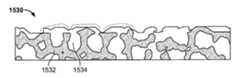
도 6은 다공성 표면의 예시적인 제1 SEM 이미지를 나타내며;
도 7은 다공성 표면의 예시적인 제2 SEM 이미지를 나타낸다.These and other objects and advantages will become apparent with reference to the following detailed description, taken in conjunction with the accompanying drawings, in which like reference numerals refer to like parts throughout.
1 shows a first view of an exemplary implant component;
Figure 2 shows a second view of an exemplary implant component;
Figure 3 shows an exemplary implant coating volume with a spherical bead surface profile;
Figure 4 shows an exemplary unit cell with a porous structure;
Figure 5 shows a cross-sectional view of an exemplary coating volume having a spherical bead profile and a porous structure;
Figure 6 shows an exemplary first SEM image of a porous surface;
Figure 7 shows an exemplary second SEM image of a porous surface.
본원에 기재된 시스템, 장치, 및 방법의 전반적인 이해를 제공하기 위해, 특정한 예시적인 실시양태가 기재될 것이다. 본원에 기재된 실시양태 및 특징은 구체적으로 비구 시스템과 관련된 용도를 기재하지만, 부품, 연결 메카니즘, 조정가능한 시스템, 고정 방법, 제조 방법, 코팅, 및 하기 요약된 다른 특징 모두는 임의의 적합한 방식으로 서로 조합될 수 있고, 다른 외과 절차(척추 관절성형술, 두개-악안면 수술 절차, 무릎 관절성형술, 어깨 관절성형술뿐만 아니라 발, 발목, 손, 및 다른 팔다리 수술 절차를 포함하나 이에 제한되지 않음)에 사용되는 임플란트 및 의료 장치에 채용되고, 적용될 수 있음을 이해해야 한다.In order to provide a thorough understanding of the systems, apparatus, and methods described herein, specific exemplary embodiments will be described. Although the embodiments and features described herein are specifically directed to applications related to acetabular systems, the components, connection mechanisms, adjustable systems, fixation methods, manufacturing methods, coatings, and other features summarized below may be used in any suitable manner Can be combined and used in other surgical procedures including but not limited to spinal arthroplasty, cranio-maxillofacial procedures, knee arthroplasty, shoulder arthroplasty, as well as foot, ankle, hand, and other limb surgical procedures Implants, and medical devices.
이들의 다양한 실시양태에서 본원에 기재된 다수의 임플란트 및 다른 장치가 임의의 적합한 보강 재료와 함께 이용될 수 있고, 보강 재료의 예로는 뼈 접합재, 적합한 고분자, 재흡수가능한 폴리우레탄, 및/또는 폴리노보 바이오머티리얼 리미티드(PolyNovo Biomaterials Limited) 사에 의해 제공되는 임의의 물질, 또는 이들의 임의의 적합한 조합물이 포함되나 이에 제한되지 않는다. 사용될 수 있는 추가의 비제한적인 잠재적 물질의 예가 하기 참고문헌에 기재되어 있다: 미국 특허 출원 공보 제2006/0051394호 "Biodegradable Polyurethane and Polyurethane Ureas", 미국 특허 출원 공보 제2005/0197422호 "Biocompatible Polymer Compositions for Dual or Multi Staged Curing", 미국 특허 출원 공보 제2005/0238683호 "Biodegradable Polyurethane/Urea Compositions", 미국 특허 출원 공보 제2007/0225387호 "Polymer Compositions for Dual or Multi Staged Curing", 미국 특허 출원 공보 제2009/0324675호 "Biocompatible Polymer Compositions", 미국 특허 출원 공보 제2009/0175921호 "Chain Extenders", 및 미국 특허 출원 공보 제2009/0099600호 "High Modulus Polyurethane and Polyurethane/Urea Compositions." 상기 참고문헌 각각은 그 전문이 본원에 참조로 포함된다.In various embodiments of these, a number of implants and other devices described herein can be used with any suitable reinforcing material, and examples of reinforcing materials include bone bonding material, a suitable polymer, a resorbable polyurethane, and / Any material provided by PolyNovo Biomaterials Limited, or any suitable combination thereof. Examples of additional non-limiting potential materials that may be used are described in the following references: U.S. Patent Application Publication No. 2006/0051394 entitled " Biodegradable Polyurethane and Polyurethane Ureas ", U.S. Patent Application Publication No. 2005/0197422 entitled "Biocompatible Polymer Compositions quot; for Dual or Multi Staged Curing ", US Patent Application Publication No. 2005/0238683 entitled " Biodegradable Polyurethane / Urea Compositions ", US Patent Application Publication No. 2007/0225387 entitled " Polymer Compositions for Dual or Multi Staged Curing & 2009/0324675 "Biocompatible Polymer Compositions ", US Patent Application Publication No. 2009/0175921" Chain Extenders ", and U.S. Patent Application Publication No. 2009/0099600 entitled "High Modulus Polyurethane and Polyurethane / Urea Compositions." Each of the above references is incorporated herein by reference in its entirety.
이하 도 1 내지 도 7을 참조하면, 특정 실시양태는 다공성 비드형 코팅을 갖는 부품 및 그의 제조 방법을 제공한다. 임플란트 및 천연 뼈는 통상 상이한 유연도를 갖기 때문에, 불균일 응력 분포가 발생할 수 있다. 결과적으로, 임플란트가 적재될 때, 일반적으로 뼈(보다 유연함)와 임플란트(보다 강직함) 사이의 계면에서는 일부 상대적인 이동이 존재한다. 따라서, 대부분의 임플란트는 뼈 접합재와 같이 상대적 이동량을 감소시키는 중간 재료를 채용한다; 그러나, 무접합재(cementless) 임플란트는 동일한 목적을 달성하기 위해서 상대 조도(relative roughness)에 의존할 수 있다.Referring now to Figures 1 to 7, certain embodiments provide a component having a porous beaded coating and a method of making the same. Because implants and natural bones usually have different degrees of flexibility, non-uniform stress distribution can occur. As a result, when the implant is loaded, there is generally some relative movement at the interface between the bone (more flexible) and the implant (more rigid). Thus, most implants employ an intermediate material that reduces the amount of relative movement, such as a bone joint material; However, cementless implants can rely on relative roughness to achieve the same purpose.
과거 오랫동안, 상대적 이동량 감소에 필요한 마찰력을 발생시키기 위해 작은 구형 비드, 박형 와이어 묶음, 및 용사(thermal-sprayed) 금속이 사용되고 있다. 임의로, 나사 및/또는 압입 끼워맞춤 특징부는 뼈에 대한 임플란트의 고정을 개선할 수 있다. 이러한 기술은 일반적으로 정형외과 전문의 커뮤니티에 의해 수용되고 있다. 그러나, 이들 코팅의 형상 특성은 공극의 위치 및 크기를 제한한다. 새로운 기술, 예컨대 비대칭 비드 또는 금속성 발포체를 채용하는 기술은 공극의 위치 및 크기를 개선하지만, 양호한 표면 텍스쳐를 갖도록 제조하는데 어려움이 있다. (예를 들어, 기계가공을 통해) 이미 다공성인 코팅 표면 내에 해치 선(hatch line)을 넣는 방안도 포함된다. 미시적 수준에서 날카로운 돌기부를 갖는 다른 다공성 표면이 제조되고 있다. 이들 돌기부는 뼈와 임플란트 사이에 상대적 이동량이 적은 경우에도 문제를 일으킬 수 있다. 더 날카로운 돌기부는 뼈 내를 파고들어 뼈 입자를 생성하거나, 또는 임플란트로부터 부러져 분리되고 임플란트-뼈 계면에서 마모된 입자를 생성할 수 있다. 이들 느슨해진 입자는 임플란트와 뼈 사이의 부착을 느슨하게 하는 것 이외에, 유해한 문제를 일으킬 수 있다.In the past, small spherical beads, thin wire bundles, and thermal-sprayed metals have been used to generate the frictional forces needed to reduce relative travel. Optionally, the screw and / or press fit feature can improve fixation of the implant to the bone. These techniques are generally accepted by the orthopedic community. However, the shape properties of these coatings limit the location and size of the voids. Techniques employing new techniques, such as asymmetric beads or metallic foams, improve the position and size of the voids, but have difficulties in manufacturing to have a good surface texture. (For example, through machining) to include a hatch line in a coating surface that is already porous. Other porous surfaces with sharp protrusions at a microscopic level are being fabricated. These protrusions can cause problems even when the relative amount of movement between the bones and the implant is small. Sharp protrusions can dig into the bone to create bone particles, or they can break apart from the implant and create worn particles at the implant-bone interface. These loosened particles can cause harmful problems in addition to loosening the adhesion between the implant and bone.
종전의 다공성 표면의 결함은 거시적 수준에서 다수의 뭉툭한 돌기부를 갖도록 텍스쳐링되는 표면을 갖고 미시적 수준에서 다공성 구조물을 갖는 임플란트를 제공함으로써 다루어진다. 뭉툭한 돌기부는 이식된 부품과 주위 뼈 사이의 상대적 이동량을 감소시키는 마찰을 발생시킨다. 공극은 주위 뼈가 임플란트 내로 성장하도록 하고, 임플란트와 뼈 사이의 상대적 이동량의 결여는 이러한 내성장을 용이하게 한다.Defects of the prior porous surface are addressed by providing an implant having a porous structure at a microscopic level with the surface textured to have a plurality of blunt protrusions at the macroscopic level. The blunt protrusions create friction that reduces the relative amount of movement between the implanted part and the surrounding bone. The pores allow the surrounding bone to grow into the implant, and the lack of relative movement between the implant and bone facilitates this endogenous growth.
뭉툭한 돌기부를 갖는 다공성 임플란트를 설계 및 형성하는데 고려해야 하는 것은 돌기부의 크기 및 밀도이다. 돌기부는 뼈가 처음 임플란트와 접촉하는 영역을 형성한다. 돌기부가 너무 크거나 또는 너무 멀리 이격되는 경우, 돌기부들 사이의 임플란트 표면적의 대부분은 뼈로부터 너무 멀어져 뼈가 임플란트 내로 성장할 수 없을 것이며, 뼈는 임플란트와 함께 중실형 계면을 형성하지 못할 수 있다. 반대로, 돌기부가 너무 작거나 또는 너무 근접하게 위치하는 경우, 이들 효과는 최소화될 것이며, 임플란트는 무른 표면 또는 다수의 집중된 날카로운 돌기부로 구성되는 표면을 갖는 종래 임플란트와 같이 동일한 문제에 직면할 수 있다. 이상적인 표면은 뼈와 임플란트 사이에 필요한 마찰을 발생시키기에 충분히 크고 여전히 다공성 표면으로의 뼈의 내성장도를 높게 하기에 충분히 작은 돌기부를 함유한다. 돌기부는 임의의 적합한 높이일 수 있으며, 바람직하게는 약 50㎛ 내지 약 2000㎛이다. 특정 용도에서, 돌기부의 높이를 200㎛ 내지 400㎛로 제한하는 것이 주위 뼈와의 바람직한 마찰 수준 및 내성장을 달성하기 위해 바람직하다.It is the size and density of the protrusions that must be considered in designing and forming a porous implant having a blunt protrusion. The protrusions form the area where the bone initially contacts the implant. If the protrusions are too large or too far apart, the majority of the implant surface area between the protrusions will be too far from the bone to allow the bone to grow into the implant, and the bone may not form a solid interface with the implant. Conversely, if the protrusions are positioned too small or too close, these effects will be minimized and the implant can face the same problems as conventional implants with surfaces consisting of a loose surface or a plurality of concentrated sharp protrusions. The ideal surface contains protrusions large enough to create the necessary friction between the bone and implant and small enough to still increase the degree of bone growth into the porous surface. The protrusion may be of any suitable height, and is preferably from about 50 [mu] m to about 2000 [mu] m. In certain applications, it is desirable to limit the height of the protrusions to 200 [mu] m to 400 [mu] m to achieve the desired level of friction and ingrowth with the surrounding bone.
이식가능 부품 표면 상의 돌기부는 부품의 일반적인 또는 특정 용도에 바람직한 임의의 적합한 형상 또는 프로파일일 수 있다. 특정 실시양태에서, 각 표면 돌기부는 임플란트 표면 위의 구의 일부로서 요철(bump) 형상화될 수 있다. 또한, 돌기부는 와이어 또는 무접합재 임플란트에 일반적인 특징부를 포함하는 임의의 다른 적합한 특징부와 같이 형상화될 수 있다.The protrusions on the surface of the implantable component may be any suitable shape or profile suitable for general or specific use of the component. In certain embodiments, each surface protrusion may be bump-shaped as part of a sphere on the implant surface. In addition, the protrusions can be shaped like wire or any other suitable feature including features common to non-bonding material implants.
도 1 및 도 2는 개선된 비구 임플란트(1500)의 일부 실시양태를 나타내며, 보강재 전체, 보강재의 일부, 플랜지, 플레이트, 다른 고정 부재, 쉘, 또는 케이지일 수 있다. 개선된 비구 임플란트(1500)는 필요한 내성장 계면의 조도 및 공극률과 함께, 임상적으로 성공적인 다공성 비드의 요철형(bumpy) 외면 형상 및 프로파일을 모방한다. 임플란트(1500)의 표면은 뭉툭한 돌기부(1502)에 의해 텍스쳐링되어 있고, 돌기부는 임플란트(1500)의 표면 상에서 실질적으로 반구형 요철로서 형상화되어 있다. 돌기부(1502)는 주위 뼈가 실질적으로 다공성 돌기부(1502) 및 돌기부들 사이의 다공성 표면적(1504) 내로 성장하도록 하면서, 주위 뼈에 대한 임플란트(1500)의 이동을 감소시키는 바람직한 마찰을 발생시키도록 사이징되고 이격된다. 상기 논의된 돌기부 높이 이외에, 돌기부(1502)의 간격 및 밀도는 생성된 마찰량 및 뼈 내성장에 영향을 끼친다. 임플란트에는 돌기부(1502)의 임의의 적합한 밀도가 사용될 수 있으며, 돌기부는 바람직하게는 약 10% 내지 약 60%의 표면을 점유한다. 돌기부는 약 0.25개의 비드/mm2 내지 약 6개의 비드/mm2의 밀도로 집중될 수 있다.Figures 1 and 2 illustrate some embodiments of the
도 1 및 도 2의 임플란트(1500)와 같은 개선된 비구 임플란트는, 임의의 적합한 접근법에 의해 형성될 수 있으며, 이하 4개의 방법 중 하나를 사용하여 형성될 수 있다.An improved acetabular implant, such as the
제1 방법은 1) 다공성 비드형 표면의 음각 압흔을 갖는 몰드를 제공하는 단계, 2) 중실형 또는 다공성일 수 있는 코팅될 임플란트 기재를 제공하는 단계, 3) 임플란트 기재와 상기 몰드 사이에 작은 비대칭 입자를 개재하는 단계, 및 4) 몰드, 임플란트 기재, 및 작은 비대칭 입자에 압력 및/또는 승온을 가하여 "성형(green)-상태" 임플란트(즉, 완전 소결에 대해 준비됨) 또는 최종 임플란트(소결됨)를 생성하며, 임플란트는 원하는 섬유주 구조물의 조도 및 공극률과 함께 임상적으로 증명된 다공성 비드형 구조물을 모방하는 외면 형상 및 프로파일을 가지며 조면화된 다공성 코팅을 갖는 것인 단계를 포함한다.The first method comprises the steps of 1) providing a mold having intaglio indentations of a porous beaded surface, 2) providing an implantable substrate to be coated, which may be solid or porous, 3) small asymmetry between the implant substrate and the mold (I. E., Prepared for complete sintering) or final implant (sintering) by applying pressure and / or elevated temperature to the mold, implant substrate, and small asymmetric particles, Wherein the implant has a roughened porous coating having an outer shape and profile that mimics a clinically proven porous beaded structure with the desired trabecular meshwork geometry and porosity.
제2 방법은 1) 다공성 비드형 임플란트의 외면 프로파일을 시뮬레이션하는 3D 모델을 생성하는 단계, 2) 임플란트 기재 볼륨의 모델을 생성하는 단계, 3) 다공성 비드형 임플란트의 외면 프로파일을 시뮬레이션하는 3D 모델을 임플란트 기재 볼륨의 3D 모델에 적용하여 요철형 예비-성형 볼륨을 형성하는 단계, 4) 요철형 예비-성형 볼륨에 원하는 상호연결된 다공성 또는 다르게는 망상 구조물을 충전하도록 알고리즘을 적용하여 다공성 임플란트 모델을 생성하는 단계, 및 5) 급속 제조 공정에서 임플란트 모델을 사용하여 임상적으로 증명된 다공성 비드형 구조물을 모방하는 외면 프로파일 형상과 함께 조면화된 다공성 텍스쳐를 갖는 임플란트를 생성하는 단계를 포함한다.The second method comprises the steps of 1) creating a 3D model that simulates the external profile of a porous bead implant, 2) creating a model of the implant-based volume, 3) a 3D model simulating the external profile of the porous bead implant Forming a concave-convex pre-forming volume by applying to the 3D model of the implant substrate volume, 4) applying a algorithm to fill the desired interconnected porous or otherwise networked structures in the irregular pre-forming volume to create a porous implant model And 5) creating an implant having a roughened porous texture with an external profile shape that mimics a clinically proven porous beaded structure using an implant model in a rapid manufacturing process.
제3 방법은 1) 다공성 비드형 표면의 외면 프로파일 형상의 음각 이미지를 모방하는 내면을 갖는 임플란트의 몰드를 제공하는 단계, 2) 복수의 작은 비대칭 입자를 제공하는 단계, 3) 몰드 내에 복수의 작은 비대칭 입자를 넣는 단계, 및 4) 몰드 및/또는 작은 비대칭 입자에 압력 및/또는 승온을 적용하여, 임상적으로 증명된 다공성 비드형 구조물을 모방하는 외면 프로파일 형상과 함께 조면화된 다공성 텍스쳐를 갖는 "성형-상태" 임플란트(즉, 완전 소결에 대해 준비됨) 또는 최종 임플란트(소결됨)를 생성하는 단계를 포함한다.The third method comprises the steps of 1) providing a mold of an implant having an inner surface that mimics an intaglio image of the outer profile profile of a porous beaded surface, 2) providing a plurality of small asymmetric particles, 3) And 4) applying pressure and / or elevated temperature to the mold and / or small asymmetric particles to form a porous texture having a roughened porous texture with an outer profile shape that mimics a clinically proven porous beaded structure To form a "form-state" implant (i. E. Ready for full sintering) or a final implant (sintered).
제4 방법은 금속성 발포체 제조의 선행 단계 동안에 발포체 부품 상에 비드형 표면의 생성을 포함하며, 이 방법은 1) 다공성 비드형 표면의 외면 프로파일 형상의 음각 이미지를 모방하는 내면을 갖는 임플란트의 몰드를 제공하는 단계, 2) 몰드 내에 1종 이상의 발포제를 적재하는 단계, 3) 다공성 비드형 표면의 외면 프로파일 형상을 모방하는 외면 형상을 갖는 상기 임플란트의 일반적인 형상 및/또는 크기로 다공성 발포체 부품 (예를 들어, 고분자, 폴리우레탄)을 형성하는 단계, 4) 몰드로부터 다공성 발포체 부품을 제거하는 단계, 5) 바인더 또는 결합제를 다공성 발포체 부품에 적용하는 단계, 6) 복수의 작은 대칭 또는 비대칭 입자 (또는 이들의 조합)를 상부에 바인더 또는 결합제를 갖는 다공성 발포체 부품에 적용하는 단계, 7) 상부에 바인더 또는 결합제 및 입자를 갖는 다공성 발포체 부품에 승온을 가하여 입자를 함께 소결하고/소결하거나 발포체 부품을 소성하여, 임상적으로 증명된 다공성 비드형 구조물을 모방하는 외면 프로파일 형상과 함께 조면화된 다공성 텍스쳐를 갖는 "성형-상태" 임플란트(즉, 완전 소결에 대해 준비됨) 또는 최종 임플란트(소결됨)를 형성하는 단계를 포함한다. 임플란트는 임상적으로 증명된 다공성-비드형 구조물을 모방하는 요철형 외면 프로파일 및 형상을 갖는다.The fourth method comprises the production of a beaded surface on a foam part during a preceding step of the production of a metallic foam, comprising the steps of: 1) forming a mold of the implant having an inner surface that mimics the engraved image of the outer profile profile of the porous beaded surface (2) loading at least one foaming agent in the mold, and (3) placing the porous foam component (e.g., a foam) into the mold with a general shape and / or size of the implant having an outer shape that mimics the profile profile of the outer surface profile of the porous beaded surface (4) removing the porous foam component from the mold, (5) applying a binder or binder to the porous foam component, (6) applying a plurality of small symmetrical or asymmetric particles To a porous foam component having a binder or binder on top, 7) applying a binder or binder to the top, The porous foam component with the admixture and particles is subjected to an elevated temperature to sinter the particles together / sinter or fuse the foam component to form a porous texture with an outer profile profile that mimics a clinically proven porous bead structure Forming a "shaped-state" implant (i. E. Ready for full sintering) or a final implant (sintered). Implants have an irregular outer profile and shape that mimics clinically proven porous-beaded structures.
임플란트의 적어도 외부를 형성하는 기재는 섬유주 구조와 닮은 벌크 다공성 망상 구조물일 수 있다. 임플란트의 하나 이상의 코어부 또는 외면부는 중실형일 수 있다 (예를 들어, 임플란트의 일부는 다른 임플란트 부품과 뼈 상호결합하도록 구성될 수 있음). 또한, 임플란트는 하나 이상의 중실형 내부를 포함할 수 있다. 예를 들어, 도 1에 나타낸 임플란트(1500)는 임플란트의 내부에 중실형 구조물을 포함할 수 있다. 구조물은 임플란트(1500)의 내부에 단일 중실형 영역 또는 다중 중실형 영역일 수 있으며, 임플란트를 지지하기 위한 일련의 구조적 리브를 제공한다. 중실형 내부 구조물은 콘크리트의 리바(rebar)와 유사한 격자 구조와 같은 임의의 적합한 형상 및 구조를 가질 수 있다. 내부 구조물이 바람직할 수 있는 영역의 예시적이지만 비제한적인 예로는, 나사 구멍 주변 영역, 증강재의 적도 영역, 또는 임의의 다른 적합한 영역이 포함된다. 일부 실시양태에서, 중합체 발포체는 용융 또는 연소되어 비드 형상을 가질 수 있거나 또는 발포체는 비드 형상의 하부 표면 상에서 중합되어 비드 형상의 표면을 갖는 최종 생성물이 형성될 수 있다. 중실형 내부 부품 이외에, 임플란트(1500)는 임플란트에 대한 추가적인 지지를 제공하기 위한 외부 플랜지 또는 다른 고정 부재와 결합할 수 있다. 예를 들어, 임플란트(1500)는 플랜지의 제1 단부에서 임플란트에 부착되고 제2 단부에서 예를 들어, 플랜지의 관통 홀 내에서 고정된 뼈 나사에 의해, 환자의 뼈에 부착되는 플랜지와 함께 이식될 수 있다. 또한, 임플란트(1500)는 임플란트의 다공성 부분에 대한 지지를 제공하기 위한 일반적인 버팀목 및 버팀대 구조물과 유사한 외부 중실형 증강재를 포함할 수 있다.The substrate forming at least the exterior of the implant may be a bulk porous network like a trabecular structure. One or more of the core or outer surface portions of the implant may be solid (e.g., a portion of the implant may be configured to bone-bond with other implant components). The implant may also include one or more solid interior portions. For example, the
급속 제조 기술의 경우는, 비드 표면 형상 및 프로파일을 가상적으로 생성하여 벌크 다공성 개체로부터 차감하거나 또는 가상 비드를 생성하여 다공성 개체와 함께 조합할 수 있다. 최종 생성물이 균질한 실시양태가 일반적으로 의도하는 것이지만, 일부에서 반드시 필수적인 것은 아니다. 임플란트의 다른 실시양태는 금속성 와이어 묶음 또는 열융사 코팅의 피크 및 밸리를 모방하는 표면 프로파일을 포함할 수 있다. 소프트웨어 모델링을 사용하여 원하는 형상의 가상 모델이 생성되면, 임의의 적합한 급속 제조 기술을 사용하여 원하는 표면 프로파일을 갖는 임플란트 부품이 생성될 수 있다. 예를 들어, 다공성 임플란트는 분말화된 금속을 사용하여 모델링된 임플란트에 "인쇄하는" 3D 인쇄 기술을 사용하여 형성될 수 있다. 이러한 접근법에서, 도 1 및 도 2의 돌기부(1502)와 같은 돌기부를 포함하는 표면 프로파일을 갖는 발포체가 생성될 수 있고, 이어서 프로파일링된 발포체는 분말화된 금속으로 내부가 충전되어 표면이 프로파일링된 다공성 미세구조물을 생성할 수 있다. 또한, 돌기부를 포함하지 않는 발포체를 사용하여 분말화된 금속을 갖는 다공성 미세구조물을 생성할 수 있고, 이어서 돌기부를 갖는 원하는 표면 프로파일이 다공성 금속 임플란트의 표면으로 각인(stamp)될 수 있다.In the case of rapid manufacturing techniques, bead surface shapes and profiles can be virtually created and subtracted from bulk porous objects, or virtual beads can be created and combined with porous objects. While homogeneous embodiments of the end products are generally intended, they are not necessarily essential in some instances. Other embodiments of the implant may include a surface profile that mimics the peaks and valleys of the metallic wire bundle or thermal coating. Once the virtual model of the desired shape is created using software modeling, any suitable implantable component with the desired surface profile can be created using the appropriate rapid manufacturing techniques. For example, porous implants can be formed using a 3D printing technique that "prints " implants modeled using powdered metal. In this approach, a foam having a surface profile comprising protrusions, such as the
상기 방식으로 제조된 임플란트의 장점은, 이들이 임상적으로 증명된 다공성 비드의 초기 뼈-결합 표면 프로파일을 갖는 일체형 공극을 함유한다는 것이다. 다시 말해서, 뼈와 임플란트 사이에 필요한 견인력을 제공하는 동일한 특징부들이 강성의 내구성 고정 표면의 내부 및 표면 주위에 뼈가 성장하도록 하는 표면을 제공하는 동일한 특징부들이다. 비제한적인 예로서, 표 A 및 표 B는 잠재적으로 적합한 비드 밀도 (간격), 및 직경의 일부 예를 나타낸다.An advantage of implants manufactured in this manner is that they contain integral voids with an initial bone-binding surface profile of clinically proven porous beads. In other words, the same features that provide the necessary traction between the bone and the implant are the same features that provide a surface that allows bone to grow around the interior and surface of the rigid durable fixation surface. As a non-limiting example, Table A and Table B show some examples of potentially suitable bead density (spacing) and diameter.
[표 A][Table A]
적어도 3개의 시계에서 (일본 제올(Jeol) 사의 SEM) 스미스 앤드 네퓨,인크(Smith & Nephew, Inc.) 사로부터 입수가능한 버밍햄 힙(Birmingham Hip)® 리서페이싱 시스템(Resurfacing system)으로 사용된 쉘 상의 선택 영역에서의 비드의 개수 및 50개의 비드의 비드 직경의 평균 및 표준 편차의 차트.At least three watches (Japan JEOL (Jeol) Inc. SEM) Smith And nepyu, Inc. (Smith & Nephew, Inc.) Birmingham can win heaps obtained from (Birmingham Hip) selected on the shell used riseopeyising® system (Resurfacing system) A chart of the number of beads in a region and the mean and standard deviation of the bead diameters of 50 beads.

[표 B][Table B]
전형적인 뼈 내성장용 비드형 제품에 대한 중실부 퍼센트Solid percent for typical bone-resorbing bead-shaped products
여기서, "중실부 퍼센트"는 그 전문이 본원에 참조로 포함되는 "의료용 임플란트의 다공성 코팅의 입체학적 평가를 위한 표준 시험 방법"이라는 제목의 ASTM F1854에 개시된 시험 방법에 기초하는 전형적인 금속조직학적 기술에 의해 생성된 비드 밀도의 2D 측정값이다.Herein, "Solid Percentage" is a typical metallographic technique based on the test method described in ASTM F1854 entitled " Standard Test Method for Stereological Assessment of Porous Coatings of Medical Implants " Lt; RTI ID = 0.0 > 2D < / RTI >
도 3은 구형 비드 볼륨(1512)이 내부에 배치된 코팅 볼륨(1510)을 나타내며, 여기서 구형 비드 볼륨(1512)은 코팅 볼륨(1510)으로부터 돌출하여 구형 비드 프로파일을 모방하는 제2 코팅 볼륨을 형성한다. 다르게는, 중실형 구형 비드가 다공성 코팅 내에 조합될 수 있다. 코팅 볼륨(1510)을 생성하기 위해서, 2개의 소프트웨어 모델을 생성한 후에 조합하여 프로파일링된 돌기부 표면을 갖는 다공성 볼륨의 최종 모델을 형성할 수 있다. 복수의 비드 볼륨(1512)을 비롯한 볼륨의 거시적 구조의 제1 모델은 소프트웨어 모델링으로 생성될 수 있으며, 도 3에 나타낸 볼륨과 실질적으로 동일하게 보일 수 있다.Figure 3 shows a
도 3에 나타낸 볼륨과 같은 거시적 볼륨에 바람직한 다공성 미시적 구조를 제조하기 위해 제2 소프트웨어 모델이 생성될 수 있다. 도 4는 예시적인 다공성 망상 구조물의 단위 셀(1520)을 나타내며, 구형 비드 프로파일을 모방하는 코팅 볼륨을 충전하도록 구성될 수 있다. 단위 셀(1520)은 버팀대(1512)의 복합 구조물로 구성된다. 버팀대(1512)의 배열은 단위 셀(1520) 내부에서 공동부(1514)를 생성하여, 이에 의해 원하는 다공성 미세구조물이 만들어진다. 버팀대(1512)의 크기 및 배열은 공동부(1514)의 개수 및 크기를 제어하기 위해 달라질 수 있다. 버팀대(1512)의 크기 및 배열을 제어함으로써, 원하는 양 및 프로파일의 다공성 구조물이 달성된다.A second software model may be generated to produce a preferred porous microstructure for a macroscopic volume such as the volume shown in FIG. FIG. 4 shows a
도 5는 (예를 들어, CAS 소프트웨어에서 도 4의 단위 셀(1520)과 같은 반복 단위 셀을 통해, 또는 상기 기재된 4개의 방법 중 임의의 하나를 사용하여) 볼륨을 망상 구조물로 교체한 후에 구형 비드 프로파일을 모방하는 도 3의 코팅 볼륨(1510)에 대응할 수 있는 코팅 볼륨(1530)의 단면도를 나타낸다. 최종 코팅 볼륨(1530)은 프로파일링된 매크로구조물 및 다공성 미세구조물 양자 모두를 보여준다. 도 5에서 점선은 코팅 볼륨(1530)의 표면 프로파일의 윤곽을 나타내고, 이식할 때 뼈와의 마찰을 발생시키는 요철형 표면을 생성하는 돌기부를 나타낸다. 중실형 구조물(1532) 및 공동부(1534)의 조합으로 구성되는 코팅 볼륨(1530)의 미세구조물은, 주위 뼈가 성장하여 공동부(1534)를 충전하고 임플란트와 뼈와의 견고한 접합을 생성하는 다공성 임플란트를 생성한다.Figure 5 illustrates a method of replacing a volume with a network structure (e.g., using CAS software, through a repeating unit cell such as
도 6은 개시된 방법에 의해 제조된 부품의 표면을 25x 배율로 촬영한 SEM 이미지(1540)를 나타낸다. 본 화상에서 표면 토포그래피는 분명하지 않다. 도 7은 개시된 방법에 의해 제조된 구조물을 50x 배율로 촬영한 SEM 이미지(1550)이다. 도 6 및 도 7에서 나타낸 구조물은 코팅 볼륨(1510 및 1530)에 대하여 상기 논의된 다공성 미세구조물을 나타내며, 중실형 매크로구조물과, 도 4에서 단위 셀(1520)과 같은 다공성 미세구조물 모델을 조합함으로써 생성될 수 있다.Figure 6 shows a
또다른 비제한적인 예로서, 이하의 차트는 다양한 실시양태에 유용한 것으로 증명된 몇몇 추가의 예시적인 파라미터를 나타낸다. 이하의 차트에서, MVIL은 평균 공동부 차단 길이(Mean Void Intercept Length)를 지칭하며, 이는 특히 공극 형상 및 크기가 균일하지 않은 구조물에서 평균 공극 크기를 특징짓는 또다른 방법이다. MVIL의 일반적으로 공지된 정의는 "격자선이 기재 계면과 평행하게 배향될 때의 측정값이다. 선이 공극을 차단하는 횟수를 공극 부피율과 함께 사용하여 평균 공극 차단 길이를 산출한다".As another non-limiting example, the following chart illustrates some additional exemplary parameters that have proved useful in various embodiments. In the following chart, MVIL refers to the Mean Void Intercept Length, which is another way of characterizing the average pore size, especially in void geometry and in non-uniform structures. The commonly known definition of MVIL is "the measured value when the grating line is oriented parallel to the substrate interface. &Quot; Calculate the average pore blocking length using the number of times the line breaks the pore with the void volume ratio.

일반적으로 약 60 내지 85%의 공극률을 제공하는 것이 바람직하다. 공극 크기는 일반적으로 약 50 내지 1000 마이크로미터의 범위일 수 있다. 상기 실시예에서, 제시된 최소 공극 크기는 약 300 마이크로미터이고, 최소 윈도우는 최대 직경을 가로질러 약 595 마이크로미터였다. 본 실시예는 비제한적인 것이며, 단지 설명을 목적으로 제공됨을 의도하는 것임을 이해해야 한다.It is generally desirable to provide porosity of about 60 to 85%. The pore size may generally range from about 50 to 1000 micrometers. In the above example, the minimum pore size suggested was about 300 micrometers and the minimum window was about 595 micrometers across the maximum diameter. It is to be understood that the present embodiments are intended to be illustrative, and not restrictive.
프로파일링된 매크로구조물 및 다공성 미세구조물 둘 모두를 갖는 임플란트를 생성하기 위한 본원에 기재된 시스템, 방법, 및 장치는, 전문 의료진이 맞춤형 환자 특이적 임플란트를 이용하도록 할 수 있다. 맞춤형 임플란트는 본원에 개시된 급속 제조 기술을 사용하여 2개 이상의 임플란트 모델을 조합하고 그 후에 모델링된 부품을 인쇄함으로써, 효율적으로 생성될 수 있다. 이에 의해, 정형 외과의사와 같은 전문 의료진이 환자의 신체부위의 결함부 또는 다른 특이 특징부에 임플란트의 크기 및 형태가 맞춰지도록 모델링하는 것을 비롯한 단일 환자에게 특이적인 임플란트를 주문할 수 있다. 또한, 상기 방법은 환자의 신체부위의 뼈를 촬영하거나 또는 다른 이용가능한 의료 화상화 및 모델링 기술을 사용하여 급속 제조에 사용하는 3D 모델을 자동적으로 생성함으로써, 자동화될 수 있다.The systems, methods, and devices described herein for creating implants with both profiled macrostructures and porous microstructures can enable a professional medical practitioner to use customized patient-specific implants. Customized implants can be efficiently created by combining two or more implant models using the rapid manufacturing techniques disclosed herein and then printing the modeled parts. This allows a single patient-specific implant to be ordered, including modeling a professional medical staff, such as an orthopedic surgeon, to match the size and shape of the implant to a defect or other specific feature of the patient's body part. The method may also be automated, such as by taking a bone of a patient's body part or automatically generating a 3D model for use in rapid manufacturing using other available medical imaging and modeling techniques.
또한, 개개의 임플란트를 맞춤화하는 능력은 전문 의료진이 임플란트의 세부적인 매크로구조물 및 미세구조물을 특정 용도의 요건에 맞춰지도록 조정할 수 있게 한다. 예를 들어, 정형 외과의사는 임플란트의 표면 상에서 돌기부의 형상, 높이, 밀도, 또는 다른 특징을 선택함으로써, 임플란트의 매크로구조물을 조정할 수 있다. 또한, 외과의사는 임플란트의 원하는 공극률을 달성하기 위해서 임플란트 내부에서 공동부의 개수 및 크기를 맞춤화할 수 있다. 일부 실시양태에서, 외과의사는 임플란트의 매크로구조물의 구조를 선택할 수도 있다. 강도 및 구조물을 위한 내부 중실형부를 포함하는 임플란트의 경우, 외과의사는 증가된 강도가 필요한 임플란트의 임의의 비균일 영역에서 상기 구조물을 제공하도록 내부 중실형부의 크기 및 위치를 맞춤화할 수 있다. 증가된 강도가 요구될 수 있는 영역의 예시적이지만 비제한적인 예는, 나사 구멍 주변 영역, 증강재의 적도 영역, 증강재의 연결 부위, 다른 곳보다 얇은 증강재 영역, 또는 임의의 다른 적합한 영역이 포함된다. 또한, 임플란트의 표면 프로파일은 임플란트의 상이한 영역에서 상이한 수준의 마찰 또는 뼈 계면에 대한 표면적을 필요로 한다면, 불균일할 수 있다. 외과의사는 임플란트의 임의 영역, 예컨대 더 높은 수준의 응력을 경험하는 영역에서 더 높은 집적도의 표면 돌기부, 및 다른 영역에서는 더 낮은 집적도의 돌기부 또는 돌기부가 전혀 없는 것을 원할 수 있다.In addition, the ability to customize individual implants allows professional caregivers to tailor the detailed macrostructures and microstructures of the implants to meet specific application requirements. For example, an orthopedic surgeon can adjust the macrostructure of an implant by selecting the shape, height, density, or other features of the protrusion on the surface of the implant. The surgeon may also customize the number and size of cavities within the implant to achieve the desired porosity of the implant. In some embodiments, the surgeon may choose the structure of the macrostructure of the implant. In the case of implants that include an internal solid for the strength and structure, the surgeon may customize the size and location of the internal solid to provide the structure in any non-uniform area of the implant that requires increased strength. An illustrative but non-limiting example of an area where increased strength may be required includes an area around the threaded hole, an equatorial area of the reinforcement material, a connecting portion of the reinforcement material, a reinforcement material area thinner than elsewhere, or any other suitable area do. Also, the surface profile of the implant may be nonuniform if it requires different levels of friction or surface area to the bone interface in different areas of the implant. The surgeon may want to have no dents or protrusions of lower density in any area of the implant, e. G., In the area experiencing a higher level of stress, and in other areas, of higher densities.
본원에 기재된 다공성 임플란트는 임플란트가 이식되는 뼈의 품질에 관계없이 양호한 접촉 표면적 및 마찰을 제공하도록 한다. 예를 들어, 연성의 해면형 뼈를 갖는 환자는 더 긴 특징부, 및 이들 특징부의 개수가 더 적은 것을 필요로 할 수 있다. 강성의 치밀형 뼈를 갖는 환자는 더 짧은 특징부를 필요로 하지만, 뼈에서 동일한 고정을 위해서 이들 특징부의 개수가 더 많아야 한다. 환자의 신체부위 및 뼈 품질의 특정 요건은 본원에 기재된 다공성 임플란트에 의해 제공되는 개별화 설계 옵션에 의해 달성될 수 있다.The porous implants described herein allow the implant to provide good contact surface area and friction regardless of the quality of the implanted bone. For example, patients with soft spongiform bones may require longer features, and fewer of these features. Patients with rigid dense bones require shorter features, but the number of these features should be greater for the same fixation in the bones. The specific requirements of the patient's body parts and bone quality can be achieved by the individualized design options provided by the porous implants described herein.
상기 내용은 본 발명의 원리를 단지 예시한 것이며, 본 발명의 시스템, 장치, 및 방법은, 예시의 목적으로 나타낸 것이지 제한하고자 하는 것은 아닌 상기 기재된 실시양태 이외의 것에 의해 수행될 수 있다. 본원에 개시된 시스템, 장치, 및 방법은 비구 시스템에서의 용도에 대해 나타냈으나, 척추 관절성형술, 두개-악안면 수술 절차, 무릎 관절성형술, 어깨 관절성형술뿐만 아니라 발, 발목, 손, 및 팔다리 수술 절차를 포함하나 이에 제한되지 않는 다른 수술 절차에서 사용되는 의료 장치에도 적용될 수 있음을 이해해야 한다.The above description is merely illustrative of the principles of the invention, and the system, apparatus and method of the present invention may be performed by means other than those described above for the purposes of illustration and not limitation. Although the systems, devices, and methods disclosed herein have been described for use in acetabular systems, they are not limited to spinal arthroplasty, craniofacial procedures, knee arthroplasty, shoulder arthroplasty as well as foot, ankle, It should be understood that the invention is also applicable to medical devices used in other surgical procedures including, but not limited to,
본 개시내용을 참고한 후, 당업자에 의해 변형 및 개질이 일어날 것이다. 개시된 특징은 본원에 기재된 하나 이상의 다른 특징과 함께 임의의 조합 및 종속 조합(다수의 인용 조합 및 종속 조합을 포함함)하여 수행될 수 있다. 그의 임의의 부품을 비롯한, 상기 기재되거나 예시된 다수의 특징은 다른 시스템과 조합되거나 통합될 수 있다. 또한, 특정한 특징은 생략되거나 수행되지 않을 수도 있다.After referring to the present disclosure, modifications and modifications will occur to those skilled in the art. The disclosed features may be implemented in any combination and subordinate combination (including multiple citation combinations and dependent combinations) with one or more other features described herein. Many of the features described or illustrated above, including any of its parts, can be combined or integrated with other systems. Also, certain features may be omitted or not performed.
교환, 치환, 및 변경의 예는 본원에 개시된 정보의 범주를 벗어나지 않으면서 당업자에 의해 확인되고, 수행될 수 있다. 본원에 인용된 모든 참고문헌은 그 전문이 참조로 포함되고, 본 출원의 일부를 구성한다.Examples of exchanges, substitutions, and modifications may be ascertained and carried out by one of ordinary skill in the art without departing from the scope of the information disclosed herein. All references cited herein are incorporated by reference in their entirety and form part of the present application.
Claims (18)
Translated fromKorean상기 다공성 제1면은 임플란트 내로 뼈 내성장을 수용하도록 사이징된 복수의 공극을 갖고,
상기 임플란트는, 다공성 제1면과 연결되고 다공성 제1면 위로 200㎛ 내지 400㎛ 솟아있는 복수의 돌기부를 더 포함하고,
복수의 돌기부는, 뼈 표면 내로 연장하지 않으며 복수의 공극 내로의 뼈 내성장에 간섭하지 않고 뼈 표면과 마찰을 생성하도록 구성되는 이식가능 정형외과용 장치.An implant having a porous first surface in contact with an orthopedic joint of a patient,
The porous first side having a plurality of cavities sized to receive intra-osteo-growth into the implant,
Wherein the implant further comprises a plurality of protrusions connected to the porous first surface and overlying the porous first surface by 200 占 퐉 to 400 占 퐉,
Wherein the plurality of protrusions are configured to extend into the bone surface and to create friction with the bone surface without interfering with intra-osseous growth into the plurality of pores.
코팅될 임플란트 기재를 제공하는 단계;
임플란트 기재와 몰드 사이에 입자를 개재시키는 단계; 및
몰드, 임플란트 기재 및 입자에 압력 또는 승온을 적용하는 단계
를 포함하는 제1항에 따른 이식가능 정형외과용 장치의 제조 방법.Providing a mold having a concave indentation of a porous beaded surface;
Providing an implant substrate to be coated;
Interposing particles between the implant substrate and the mold; And
Applying pressure or elevated temperature to the mold, implant substrate and particles
≪ / RTI > The method of claim 1, wherein the implantable orthopedic device further comprises:
임플란트 기재 볼륨의 3차원 모델을 생성하는 단계;
임플란트 기재 볼륨의 3차원 모델에 다공성 비드형 임플란트의 외면 프로파일을 시뮬레이션하는 3차원 모델을 적용하여 예비-성형 볼륨을 생성하는 단계;
예비-성형 볼륨에 원하는 망상 구조물을 충전하여 다공성 임플란트 모델을 생성하는 단계; 및
다공성 임플란트 모델을 사용하여 임플란트를 형성하는 단계
를 포함하는 제1항에 따른 이식가능 정형외과용 장치의 제조 방법.Creating a three-dimensional model that simulates an external profile of a porous bead implant;
Creating a three-dimensional model of the implant substrate volume;
Generating a pre-formed volume by applying a three-dimensional model simulating an outer profile of a porous bead implant to a three-dimensional model of the volume of the implant substrate;
Filling the pre-shaping volume with a desired mesh structure to create a porous implant model; And
The step of forming the implant using the porous implant model
≪ / RTI > The method of claim 1, wherein the implantable orthopedic device further comprises:
복수의 입자를 제공하는 단계;
복수의 입자를 몰드 내에 넣는 단계; 및
몰드에 압력 또는 승온을 적용하는 단계
를 포함하는 제1항에 따른 이식가능 정형외과용 장치의 제조 방법.Providing a mold of an implant having an inner surface that mimics an engraved image of an outer profile profile of a porous beaded surface;
Providing a plurality of particles;
Placing a plurality of particles in a mold; And
Applying pressure or elevated temperature to the mold
≪ / RTI > The method of claim 1, wherein the implantable orthopedic device further comprises:
몰드 내에 1종 이상의 발포제를 적재하는 단계;
다공성 비드형 표면의 외면 프로파일 형상을 모방하는 외면 형상을 갖는 임플란트의 형상 또는 크기로 다공성 발포체 부품을 생성하는 단계;
몰드로부터 다공성 발포체 부품을 제거하는 단계;
다공성 발포체 부품에 결합제를 적용하는 단계;
복수의 대칭 또는 비대칭 입자를, 상부에 결합제를 갖는 다공성 발포체 부품에 적용하는 단계; 및
상부에 결합제 및 입자를 갖는 다공성 발포체 부품에 승온을 적용하여 입자를 함께 소결하고 발포체 부품을 소성하여, 임상적으로 증명된 다공성 비드형 구조물을 모방하는 외면 프로파일 형상과 함께 조면화된 다공성 텍스쳐를 갖는 임플란트를 형성하는 단계
를 포함하는 이식가능 정형외과용 장치의 제조 방법.Providing a mold of an implant having an inner surface that mimics an engraved image of an outer profile profile of a porous beaded surface;
Loading at least one foaming agent in the mold;
Creating a porous foam part in the shape or size of an implant having an outer surface shape that mimics an outer profile profile of a porous beaded surface;
Removing the porous foam component from the mold;
Applying a binder to the porous foam component;
Applying a plurality of symmetrical or asymmetric particles to a porous foam component having a binder thereon; And
Applying a temperature rise to a porous foam component having a binder and particles thereon to sinter the particles together and firing the foam component to form a porous texture having a roughened porous texture with an outer profile shape that mimics a clinically proven porous bead- Step of forming an implant
≪ / RTI >
상기 임플란트는, 다공성 표면으로부터 연장되고 다공성 표면 위로 솟아있는 복수의 돌기부를 더 포함하고,
복수의 돌기부는 제곱 밀리미터당 0.25개의 돌기부 내지 제곱 밀리미터당 6개의 돌기부의 집중도를 갖고,
복수의 돌기부는 복수의 공극 내로의 뼈 내성장에 간섭하지 않고 뼈 표면과 마찰식으로(frictionally) 결합되도록 구성되는 이식가능 정형외과용 장치.An implantable orthopedic device comprising an implant having a porous surface forming a plurality of voids sized to receive intra-osteogenesis into the implant,
Wherein the implant further comprises a plurality of protrusions extending from the porous surface and rising above the porous surface,
The plurality of protrusions has a density of 0.25 protrusions per square millimeter to 6 protrusions per square millimeter,
Wherein the plurality of protrusions are configured to frictionally engage the bone surface without interfering with the intra-osseous growth into the plurality of pores.
Applications Claiming Priority (9)
| Application Number | Priority Date | Filing Date | Title |
|---|---|---|---|
| US35270510P | 2010-06-08 | 2010-06-08 | |
| US35272210P | 2010-06-08 | 2010-06-08 | |
| US61/352,722 | 2010-06-08 | ||
| US61/352,705 | 2010-06-08 | ||
| US42290310P | 2010-12-14 | 2010-12-14 | |
| US61/422,903 | 2010-12-14 | ||
| US201161466817P | 2011-03-23 | 2011-03-23 | |
| US61/466,817 | 2011-03-23 | ||
| PCT/US2011/039658WO2011156510A2 (en) | 2010-06-08 | 2011-06-08 | Implant components and methods |
Publications (2)
| Publication Number | Publication Date |
|---|---|
| KR20140031828A KR20140031828A (en) | 2014-03-13 |
| KR101904030B1true KR101904030B1 (en) | 2018-10-05 |
Family
ID=45098648
Family Applications (2)
| Application Number | Title | Priority Date | Filing Date |
|---|---|---|---|
| KR1020137000385AActiveKR101904030B1 (en) | 2010-06-08 | 2011-06-08 | Implant components and methods |
| KR1020137000339ACeasedKR20140019764A (en) | 2010-06-08 | 2011-06-08 | Implant components and methods |
Family Applications After (1)
| Application Number | Title | Priority Date | Filing Date |
|---|---|---|---|
| KR1020137000339ACeasedKR20140019764A (en) | 2010-06-08 | 2011-06-08 | Implant components and methods |
Country Status (10)
| Country | Link |
|---|---|
| US (17) | US20120089235A1 (en) |
| EP (5) | EP4111991A3 (en) |
| JP (3) | JP5885354B2 (en) |
| KR (2) | KR101904030B1 (en) |
| CN (4) | CN103037812A (en) |
| AU (6) | AU2011264852B2 (en) |
| BR (3) | BR112012031296A2 (en) |
| CA (3) | CA2802101A1 (en) |
| RU (4) | RU2012157129A (en) |
| WO (7) | WO2011156509A2 (en) |
Families Citing this family (160)
| Publication number | Priority date | Publication date | Assignee | Title |
|---|---|---|---|---|
| US20060147332A1 (en) | 2004-12-30 | 2006-07-06 | Howmedica Osteonics Corp. | Laser-produced porous structure |
| AU2003261497B2 (en) | 2002-11-08 | 2009-02-26 | Howmedica Osteonics Corp. | Laser-produced porous surface |
| US8728387B2 (en)* | 2005-12-06 | 2014-05-20 | Howmedica Osteonics Corp. | Laser-produced porous surface |
| US9308300B2 (en)* | 2007-04-19 | 2016-04-12 | Smith & Nephew, Inc. | Prosthetic implants |
| GB0804998D0 (en)* | 2008-03-18 | 2008-04-16 | Depuy Ireland Ltd | A cup component of an orthopaedic joint prosthesis |
| GB0809721D0 (en)* | 2008-05-28 | 2008-07-02 | Univ Bath | Improvements in or relating to joints and/or implants |
| US8383187B2 (en)* | 2009-02-19 | 2013-02-26 | Depuy Products, Inc. | Rough porous constructs |
| CA2753488C (en)* | 2009-02-25 | 2014-04-29 | Mohamed Rashwan Mahfouz | Customized orthopaedic implants and related methods |
| FR2950525B1 (en) | 2009-09-28 | 2013-05-10 | Thomas Gradel | HIP PROTHETIC COTYL WITH EXTERNAL FASTENING |
| IT1398443B1 (en)* | 2010-02-26 | 2013-02-22 | Lima Lto S P A Ora Limacorporate Spa | INTEGRATED PROSTHETIC ELEMENT |
| RU2012157129A (en)* | 2010-06-08 | 2014-07-20 | Смит Энд Нефью, Инк. | IMPLANT AND METHODS OF ITS MANUFACTURE |
| WO2012015945A2 (en) | 2010-07-29 | 2012-02-02 | Mayo Foundation For Medical Education And Research | Acetabular cup prosthesis |
| WO2012021764A2 (en)* | 2010-08-13 | 2012-02-16 | Smith & Nephew, Inc. | Orthopaedic implants and methods |
| SE535187C2 (en)* | 2010-09-10 | 2012-05-15 | Fumex Ab | Joint construction, ventilation arm and ventilation system |
| US9034048B2 (en)* | 2011-01-26 | 2015-05-19 | John A. Choren | Orthopaedic implants and methods of forming implant structures |
| GB201114059D0 (en)* | 2011-08-16 | 2011-09-28 | Depuy Ireland | Attachment mechanism |
| US9132021B2 (en) | 2011-10-07 | 2015-09-15 | Pioneer Surgical Technology, Inc. | Intervertebral implant |
| US8771354B2 (en) | 2011-10-26 | 2014-07-08 | George J. Picha | Hard-tissue implant |
| US10039556B2 (en)* | 2011-11-10 | 2018-08-07 | David Michael Burt | Arthroscopic total shoulder arthroplasty |
| EP3326558B1 (en) | 2011-11-14 | 2025-04-30 | The University of British Columbia | Intramedullary fixation system for management of pelvic and acetabular fractures |
| EP2787929B1 (en)* | 2011-12-07 | 2019-05-15 | Smith&Nephew, Inc. | Orthopedic augments having recessed pockets |
| JP6282596B2 (en) | 2011-12-07 | 2018-02-21 | スミス アンド ネフュー インコーポレイテッド | Orthopedic implant augment |
| GB201121529D0 (en)* | 2011-12-15 | 2012-01-25 | Springer Thorwald | A prosthetic acetabular cup |
| US9005304B2 (en) | 2012-01-18 | 2015-04-14 | George J. Haidukewych | Acetabular prosthetic device |
| US8906108B2 (en)* | 2012-06-18 | 2014-12-09 | DePuy Synthes Products, LLC | Dual modulus hip stem and method of making the same |
| US9918724B2 (en)* | 2012-12-27 | 2018-03-20 | Wright Medical Technology, Inc. | Ankle replacement system and method |
| US9271839B2 (en) | 2013-03-14 | 2016-03-01 | DePuy Synthes Products, Inc. | Femoral component for an implantable hip prosthesis |
| EP2815726B1 (en)* | 2013-06-19 | 2015-08-12 | Arthrex, Inc. | Humerus implant |
| AU2013397940B2 (en)* | 2013-08-15 | 2019-03-14 | George J. Haidukewych | Acetabular prosthetic device |
| AU2014317989A1 (en)* | 2013-09-05 | 2016-03-17 | Smith & Nephew, Inc. | Patient-matched acetabular augment with alignment guide |
| CN106456331A (en)* | 2014-03-04 | 2017-02-22 | 皇家墨尔本理工大学 | Method for producing custom orthopedic implants |
| WO2015134750A1 (en) | 2014-03-06 | 2015-09-11 | University Of British Columbia | Shape adaptable intramedullary fixation device |
| US10524917B2 (en) | 2014-06-05 | 2020-01-07 | Ossis Limited | Implant surfaces |
| JP6389002B2 (en) | 2014-10-14 | 2018-09-12 | ザ ユニヴァーシティ オブ ブリティッシュ コロンビア | System and method for intramedullary bone fixation |
| US10420597B2 (en) | 2014-12-16 | 2019-09-24 | Arthrex, Inc. | Surgical implant with porous region |
| RU2017125255A (en)* | 2014-12-16 | 2019-01-18 | Керамтек Гмбх | INTERDERVERSE CAGES AND INSTALLATION INSTRUMENTS |
| HK1246626A1 (en)* | 2015-01-09 | 2018-09-14 | 孚美公司 | Rigid segmented flexible anchors |
| US10098746B1 (en) | 2015-02-13 | 2018-10-16 | Nextstep Arthropedix, LLC | Medical implants having desired surface features and methods of manufacturing |
| US10363145B2 (en)* | 2015-02-23 | 2019-07-30 | Amendia, Inc. | Lateral plate and spinal implant system and method |
| EP3291767B1 (en)* | 2015-04-29 | 2020-05-06 | Biomet Manufacturing, LLC | Threaded augmentable acetabular shell with augments |
| US10492921B2 (en) | 2015-04-29 | 2019-12-03 | Institute for Musculoskeletal Science and Education, Ltd. | Implant with arched bone contacting elements |
| JP6768001B2 (en) | 2015-04-29 | 2020-10-14 | インスティテュート フォー マスキュロスケレタル サイエンス アンド エジュケイション,リミテッド | Coiled implants and systems and how to make them |
| US10449051B2 (en) | 2015-04-29 | 2019-10-22 | Institute for Musculoskeletal Science and Education, Ltd. | Implant with curved bone contacting elements |
| CN104887361B (en)* | 2015-05-14 | 2017-02-22 | 青岛大学附属医院 | Fabrication template system for custom individual artificial total hip replacement operation acetabulum |
| CN104840278B (en)* | 2015-05-25 | 2017-06-06 | 北京爱康宜诚医疗器材股份有限公司 | Acetabular cup and artificial hip joint |
| EP3111892B1 (en)* | 2015-06-30 | 2018-09-12 | Jossi Holding AG | Implant and method for coating an implant base body |
| ES2758427T3 (en)* | 2015-07-09 | 2020-05-05 | Link Waldemar Gmbh Co | Hollow sleeve augmentation device |
| BR112017028272A2 (en) | 2015-07-09 | 2018-09-04 | Link Waldemar Gmbh Co | hinged joint sleeve augmentation device |
| CN108135703B (en) | 2015-07-27 | 2020-06-23 | 黑普创新技术有限责任公司 | Drill guide for acetabular cup fasteners |
| CN105078620A (en)* | 2015-08-04 | 2015-11-25 | 江苏奥康尼医疗科技发展有限公司 | Artificial shoulder joint prosthesis made from organic polymer materials |
| GB2536520A (en)* | 2015-10-21 | 2016-09-21 | Jri Orthopaedics Ltd | Clamping device |
| US9901002B2 (en) | 2016-02-24 | 2018-02-20 | Microsoft Technology Licensing, Llc | Structures having a molded liner attached to a substrate |
| WO2017192632A1 (en) | 2016-05-03 | 2017-11-09 | Additive Orthopaedics, LLC | Bone fixation device and method of use |
| TWI576033B (en)* | 2016-05-06 | 2017-03-21 | 旭德科技股份有限公司 | Circuit substrate and manufacturing method thereof |
| US11045307B2 (en) | 2016-05-11 | 2021-06-29 | Establishment Labs S.A. | Medical implants and methods of preparation thereof |
| NL2016867B1 (en) | 2016-05-31 | 2017-12-11 | Umc Utrecht Holding Bv | Implant, fitting plate and method for manufacturing an implant and fitting plate |
| WO2017210695A1 (en) | 2016-06-03 | 2017-12-07 | Additive Orthopaedics, LLC | Bone fixation devices |
| US20200000595A1 (en) | 2016-06-07 | 2020-01-02 | HD LifeSciences LLC | High X-Ray Lucency Lattice Structures |
| US11589994B2 (en) | 2016-07-08 | 2023-02-28 | Biomet Manufacturing, Llc | Augments, systems and methods for acetabular implants |
| US10779948B2 (en) | 2016-07-08 | 2020-09-22 | Beijing AK Medical Co., Ltd. | Acetabular defect reconstructive prosthesis |
| US10835383B2 (en) | 2016-07-15 | 2020-11-17 | Encore Medical, L.P. | Glenosphere with flange for augmented fixation and related methods |
| AU2017297403B2 (en) | 2016-07-15 | 2022-04-21 | DJO Global, Inc. | Glenosphere with flange for augmented fixation and related methods |
| US11058468B2 (en) | 2016-07-29 | 2021-07-13 | Additive Orthopaedics, LLC | Bone fixation device and method of use |
| US10456262B2 (en) | 2016-08-02 | 2019-10-29 | Howmedica Osteonics Corp. | Patient-specific implant flanges with bone side porous ridges |
| EP3522803A4 (en) | 2016-10-05 | 2020-05-27 | The University of British Columbia | Intramedullary fixation device with shape locking interface |
| US10478312B2 (en) | 2016-10-25 | 2019-11-19 | Institute for Musculoskeletal Science and Education, Ltd. | Implant with protected fusion zones |
| US11033394B2 (en) | 2016-10-25 | 2021-06-15 | Institute for Musculoskeletal Science and Education, Ltd. | Implant with multi-layer bone interfacing lattice |
| CN106510904B (en)* | 2016-12-12 | 2018-06-01 | 吴栋 | A kind of femoral stem component of artificial hip joint and preparation method thereof |
| CN107252342A (en)* | 2017-01-17 | 2017-10-17 | 吴栋 | A kind of acetabular bone screw and preparation method thereof |
| CA3061043A1 (en) | 2017-02-14 | 2018-08-23 | HD LifeSciences LLC | High x-ray lucency lattice structures and variably x-ray lucent markers |
| US11000378B2 (en)* | 2017-02-14 | 2021-05-11 | Surgical Device Innovations, LLC | Acetabular surgical implant for segmental pelvic defect and methods of use and manufacture |
| EP3592283B1 (en) | 2017-03-10 | 2024-05-08 | Alps Holding Llc | Hard-tissue implant comprising a bulk implant, a face, pillars, slots, and at least one support member |
| WO2018165403A1 (en)* | 2017-03-10 | 2018-09-13 | Applied Medical Research, Inc. | Hard-tissue stem implant comprising a bulk stem implant, a face, pillars for contacting a cancellous portion of a hard tissue, and slots, wherein the pillars are prearranged to match an underlying structure of the cancellous portion |
| US11324606B2 (en) | 2017-03-10 | 2022-05-10 | Gary A. Zwick | Spinal interbody cage comprising a bulk interbody cage, a top face, a bottom face, pillars, and slots |
| US10512549B2 (en) | 2017-03-13 | 2019-12-24 | Institute for Musculoskeletal Science and Education, Ltd. | Implant with structural members arranged around a ring |
| CA3058365A1 (en) | 2017-04-01 | 2018-10-04 | HD LifeSciences LLC | Three-dimensional lattice structures for implants |
| EP3606473A4 (en) | 2017-04-01 | 2020-12-30 | HD Lifesciences LLC | FLUID INTERFACE SYSTEM FOR IMPLANTS |
| US20180318110A1 (en)* | 2017-05-08 | 2018-11-08 | Depuy Ireland Unlimited Company | Trial acetabular liners |
| EP3403617B1 (en) | 2017-05-19 | 2020-03-18 | Tornier | Augment insert, shoulder prosthesis and kit comprising the augment insert |
| EP3415108B1 (en)* | 2017-05-25 | 2024-09-04 | Stryker European Operations Holdings LLC | Fusion cage with integrated fixation and insertion features |
| US12127942B2 (en)* | 2017-05-31 | 2024-10-29 | Zimmer, Inc. | Customizable augments and methods for acetabular implants |
| US11006981B2 (en) | 2017-07-07 | 2021-05-18 | K2M, Inc. | Surgical implant and methods of additive manufacturing |
| WO2019051260A1 (en) | 2017-09-08 | 2019-03-14 | Pioneer Surgical Technology, Inc. | Intervertebral implants, instruments, and methods |
| US10751186B2 (en) | 2017-09-12 | 2020-08-25 | Zimmer, Inc. | Methods for attaching acetabular augments together or to acetabular shells |
| CN107550603B (en)* | 2017-09-29 | 2024-01-23 | 辽宁禾润新材料科技有限公司 | Artificial rib |
| USD907771S1 (en) | 2017-10-09 | 2021-01-12 | Pioneer Surgical Technology, Inc. | Intervertebral implant |
| US10940015B2 (en) | 2017-11-21 | 2021-03-09 | Institute for Musculoskeletal Science and Education, Ltd. | Implant with improved flow characteristics |
| US10744001B2 (en) | 2017-11-21 | 2020-08-18 | Institute for Musculoskeletal Science and Education, Ltd. | Implant with improved bone contact |
| WO2019152893A1 (en)* | 2018-02-01 | 2019-08-08 | Revision Technologies Llc | Acetabular joint prosthesis |
| US10667917B2 (en) | 2018-02-01 | 2020-06-02 | OrbisMV LLC | Acetabular joint prosthesis |
| WO2019153010A1 (en) | 2018-02-05 | 2019-08-08 | OrbisMV LLC | Medical implant surface treatment and method |
| US11147679B2 (en) | 2018-02-05 | 2021-10-19 | Paragon Advanced Technologies, Inc. | Bone fixation device |
| RU2692531C1 (en)* | 2018-02-06 | 2019-06-25 | Александр Иванович Колесник | Reposition-fixation support ring for operative treatment of displaced fractures of cotyloid cavity |
| GB201802109D0 (en)* | 2018-02-09 | 2018-03-28 | Depuy Ireland Ultd Co | Medical implants comprising anti-infective surfaces |
| WO2019191299A1 (en) | 2018-03-27 | 2019-10-03 | San Diego State University | In situ partially degradable separation interface for fabrication of complex near net shape objects by pressure assisted sintering |
| US11278427B2 (en) | 2018-04-10 | 2022-03-22 | Gary A. Zick, Trustee Of The Everest Trust Uta April 20, 2017 | Spinal interbody cage comprising top and bottom faces with mesh structures, pillars and slots |
| KR102115225B1 (en)* | 2018-06-20 | 2020-05-27 | 한국생산기술연구원 | One-step manufacturing method of laminated molding porous component |
| CN112399837A (en) | 2018-07-11 | 2021-02-23 | 史密夫和内修有限公司 | Flexible acetabular implant |
| EP3826582A4 (en) | 2018-07-26 | 2022-05-25 | Nanohive Medical LLC | DYNAMIC IMPLANT FIXATION PLATE |
| CN108969151A (en)* | 2018-07-26 | 2018-12-11 | 肖建林 | Bias acetabular bone mortar cup prosthesis winged |
| RU187804U1 (en)* | 2018-07-31 | 2019-03-19 | Федеральное государственное бюджетное учреждение "Новосибирский научно-исследовательский институт травматологии и ортопедии им. Я.Л. Цивьяна" Министерства здравоохранения Российской Федерации (ФГБУ "ННИИТО им. Я.Л. Цивьяна" Минздрава России) | Device for replacing a bone defect in the acetabulum |
| RU2713519C1 (en)* | 2018-07-31 | 2020-02-05 | Федеральное государственное бюджетное учреждение "Новосибирский научно-исследовательский институт травматологии и ортопедии им. Я.Л. Цивьяна" Министерства здравоохранения Российской Федерации (ФГБУ "ННИИТО им. Я.Л. Цивьяна" Минздрава России) | Device for cotyloid defect replacement in cotyloid cavity |
| RU2692526C1 (en)* | 2018-09-25 | 2019-06-26 | Александр Иванович Колесник | Universal reposition-fixation ring with dynamic compression for surgical treatment of displaced fractures of acetabulum |
| CN112912022A (en) | 2018-10-17 | 2021-06-04 | 不列颠哥伦比亚大学 | Bone fixation device and system |
| US11312071B2 (en) | 2018-11-12 | 2022-04-26 | Ossur Iceland Ehf | Additive manufacturing system, method and corresponding components for making elastomeric structures |
| EP3666228A1 (en)* | 2018-12-14 | 2020-06-17 | Howmedica Osteonics Corp. | Augmented, just-in-time, patient-specific implant manufacture |
| US11376128B2 (en) | 2018-12-31 | 2022-07-05 | Depuy Ireland Unlimited Company | Acetabular orthopaedic prosthesis and method |
| US11497617B2 (en) | 2019-01-16 | 2022-11-15 | Nanohive Medical Llc | Variable depth implants |
| CN113507903A (en)* | 2019-03-25 | 2021-10-15 | 史密夫和内修有限公司 | Acetabular device for hip revision surgery |
| US11083585B2 (en) | 2019-05-09 | 2021-08-10 | Howmedica Osteonics Corp. | Spring retained femoral augment |
| US10974667B2 (en) | 2019-08-04 | 2021-04-13 | Michael McKinney | Apparatus, device and method enabling repeated coupling and decoupling of physical objects |
| JP7335428B2 (en) | 2019-09-11 | 2023-08-29 | アルプス ホールディング エルエルシー | An implant comprising a first set and a second set of pillars for attaching a tendon or ligament to hard tissue |
| US11517441B2 (en)* | 2019-09-13 | 2022-12-06 | Smith & Nephew, Inc. | Acetabular apparatus with dual mobility for hip revision surgery |
| US11534307B2 (en) | 2019-09-16 | 2022-12-27 | K2M, Inc. | 3D printed cervical standalone implant |
| RU2721285C1 (en)* | 2019-10-30 | 2020-05-18 | Федеральное государственное бюджетное учреждение "Национальный медицинский исследовательский центр травматологии и ортопедии имени Н.Н. Приорова" Министерства здравоохранения Российской Федерации (ФГБУ "НМИЦ ТО им. Н.Н. Приорова" Минздрава России) | Method of open reduction and fixation of shifted fractures of cotyloid cavity in experiment |
| EP4057947A1 (en) | 2019-11-12 | 2022-09-21 | Ossur Iceland Ehf | Ventilated prosthetic liner |
| US12171666B2 (en)* | 2019-12-10 | 2024-12-24 | Depuy Ireland Unlimited Company | Metal reinforced acetabular shell liner |
| US11628066B2 (en) | 2019-12-11 | 2023-04-18 | Depuy Ireland Unlimited Company | Ceramic acetabular shell liner with a metal ring having a lead-in surface |
| US11291549B2 (en) | 2019-12-11 | 2022-04-05 | Depuy Ireland Unlimited Company | Ceramic acetabular shell liners with augments |
| RU2738139C1 (en)* | 2019-12-25 | 2020-12-08 | Александр Иванович Колесник | Universal reposition-fixation ring with dynamic compression for surgical treatment of complex shifted fractures of cotyloid cavity |
| CN110909838B (en)* | 2019-12-25 | 2025-02-28 | 宁波大学附属第一医院 | An acceptance device for orthopedic implants |
| RU2723765C1 (en)* | 2019-12-25 | 2020-06-17 | Колесник Александр Иванович | Universal reposition-fixation ring with dynamic compression for surgical treatment of comminuted fractures of cotyloid cavity |
| EP4104771A4 (en)* | 2020-02-10 | 2023-11-01 | Ames Medical Prosthetic Solutions, S.A.U. | PROSTHESIS |
| WO2021202101A1 (en)* | 2020-04-01 | 2021-10-07 | Arthrex, Inc. | Systems and methods of forming orthopaedic implants including printed augments |
| DE102020109617A1 (en)* | 2020-04-07 | 2021-10-07 | Aesculap Ag | Hip socket and revision hip joint endoprosthesis |
| TWI751612B (en)* | 2020-07-17 | 2022-01-01 | 台灣創新材料股份有限公司 | Method for producing porous microstructure |
| US11236184B1 (en) | 2020-07-17 | 2022-02-01 | Tantti Laboratory Inc. | Method for producing porous microstructure |
| RU2752032C1 (en)* | 2020-07-22 | 2021-07-22 | Федеральное государственное бюджетное учреждение "Национальный медицинский исследовательский центр травматологии и ортопедии имени Н.Н. Приорова" Министерства здравоохранения Российской Федерации (ФГБУ "НМИЦ ТО им. Приорова" Минздрава России) | Device for open, sparing reduction of columns and acetabular fragments |
| KR102472323B1 (en) | 2020-08-21 | 2022-12-01 | 주식회사 코렌텍 | Augment Implant |
| CN111870404B (en)* | 2020-09-07 | 2024-11-26 | 北京爱康宜诚医疗器材有限公司 | External cup and hip joint prosthesis having the same |
| RU2756429C1 (en)* | 2020-09-10 | 2021-09-30 | Антон Васильевич Овчаренко | Apparatus for open low-traumatic reposition of acetabular columns and fragments |
| AU2021106303A4 (en)* | 2020-09-24 | 2021-11-04 | Signature Orthopaedics Europe Ltd | Modular acetabular cup augment apparatus |
| US12280540B2 (en) | 2020-09-27 | 2025-04-22 | San Diego State University Research Foundation | In situ partially degradable separation interface for fabrication of complex near net shape objects by pressure assisted sintering |
| RU2751520C1 (en)* | 2020-10-20 | 2021-07-14 | Александр Иванович Колесник | Method for open low-traumatic reposition of pillars and fragments of acetabulum in the experiment |
| KR102413389B1 (en)* | 2020-11-10 | 2022-06-29 | 주식회사 코렌텍 | Modular Augment |
| CN112274305B (en)* | 2020-11-11 | 2024-12-10 | 北京爱康宜诚医疗器材有限公司 | An expandable prosthesis for cancellous bone reconstruction |
| US12121271B2 (en) | 2021-02-09 | 2024-10-22 | Rtg Scientific, Llc | Femoral fixation devices, systems, and methods |
| US11883081B2 (en) | 2020-11-19 | 2024-01-30 | Rtg Scientific, Llc | Fastening devices, systems, and methods |
| KR102269037B1 (en)* | 2020-12-17 | 2021-06-25 | 주식회사 건바이오 | Mutifunctional medical polyurethane film having improved permeability by controlling fine porosity and method of manufacturing the same |
| CN112535554A (en)* | 2020-12-19 | 2021-03-23 | 经纬医疗器材制造(深圳)有限公司 | Three-dimensional metal outer cup and manufacturing method thereof |
| US20220249131A1 (en) | 2021-02-09 | 2022-08-11 | Rtg Scientific, Llc | Fastening devices, systems, and methods |
| US11737883B2 (en)* | 2021-03-02 | 2023-08-29 | Arthrex, Inc. | Orthopaedic implants including breakaway fastener |
| US11918475B2 (en) | 2021-03-31 | 2024-03-05 | DePuy Synthes Products, Inc. | Modular acetabular surgical implant assembly |
| US11819415B2 (en)* | 2021-04-02 | 2023-11-21 | Arthrex, Inc. | Orthopaedic implant systems including internal networks and methods of repair |
| KR102568192B1 (en) | 2021-04-07 | 2023-08-22 | 주식회사 코렌텍 | Augment Implant With Heterogeneous Porous Structure |
| US12376964B2 (en) | 2021-04-30 | 2025-08-05 | Depuy Ireland Unlimited Company | Apparatus and method for locking an acetabular liner to an acetabular cup |
| US12042389B2 (en) | 2021-04-30 | 2024-07-23 | Depuy Ireland Unlimited Company | Apparatus and method for installing an acetabular liner on an acetabular cup |
| US12329629B2 (en) | 2021-06-08 | 2025-06-17 | Howmedica Osteonics Corp. | Additive manufacturing of porous coatings separate from substrate |
| AU2022326436A1 (en) | 2021-08-10 | 2024-02-15 | Rtg Scientific, Llc | Bone fixation devices, systems, methods, and instruments |
| US11944544B2 (en) | 2021-11-19 | 2024-04-02 | Arthrology Consulting, Llc | Expandable augment system for acetabular cup |
| JP2025512388A (en)* | 2022-04-13 | 2025-04-17 | アールティージー サイエンティフィック,リミテッド ライアビリティー カンパニー | Bone implants, systems and methods |
| US20230346561A1 (en)* | 2022-04-29 | 2023-11-02 | Depuy Ireland Unlimited Company | Three-dimensional porous structures for bone ingrowth and methods for producing |
| US12042390B2 (en) | 2022-05-10 | 2024-07-23 | Depuy Ireland Unlimited Company | Acetabular prosthesis with adjustable acetabular cup cages |
| CN115607340A (en)* | 2022-11-02 | 2023-01-17 | 叶树楠 | Acetabular Prosthetics and Acetabular Prosthetic Systems |
| WO2024252425A1 (en)* | 2023-06-07 | 2024-12-12 | Meril Healthcare Pvt. Ltd | Augments for osteo implants |
| WO2025042873A1 (en) | 2023-08-24 | 2025-02-27 | Smith & Nephew, Inc. | Porous augments |
| CN116807694B (en)* | 2023-08-25 | 2023-12-19 | 北京爱康宜诚医疗器材有限公司 | Femoral head prosthetic prosthesis |
| CN118680731B (en)* | 2024-07-15 | 2025-02-28 | 北京力达康科技有限公司 | A 3D printed individualized modular acetabular bone defect reconstruction prosthesis and preparation method thereof |
| CN118557339B (en)* | 2024-08-01 | 2024-10-22 | 吉林大学 | A rigid-flexible coupling pelvic prosthesis with buffering function |
| CN119632733B (en)* | 2025-02-19 | 2025-08-01 | 北京理贝尔生物工程研究所有限公司 | Acetabular prosthesis |
Citations (4)
| Publication number | Priority date | Publication date | Assignee | Title |
|---|---|---|---|---|
| US5906234A (en)* | 1996-10-22 | 1999-05-25 | Johnson & Johnson Professional, Inc. | Investment casting |
| US6209621B1 (en) | 1995-07-07 | 2001-04-03 | Depuy Orthopaedics, Inc. | Implantable prostheses with metallic porous bead preforms applied during casting and method of forming the same |
| JP2006230722A (en) | 2005-02-25 | 2006-09-07 | Takiron Co Ltd | Biomaterial for artificial cartilage |
| JP2009526614A (en) | 2006-02-17 | 2009-07-23 | バイオメト マニファクチャリング コーポレイション | Method and apparatus for forming porous metal implant |
Family Cites Families (264)
| Publication number | Priority date | Publication date | Assignee | Title |
|---|---|---|---|---|
| CH552383A (en) | 1972-04-06 | 1974-08-15 | Oscobal Ag | Femoral head prosthesis. |
| CH555672A (en) | 1972-09-06 | 1974-11-15 | Oscobal Ag | PAN FOR HIP PROSTHESIS. |
| DE2250501C3 (en) | 1972-10-14 | 1975-04-30 | Artur 7241 Tumlingen Fischer | Fixing means for the socket of a hip joint prosthesis |
| US3840904A (en)* | 1973-04-30 | 1974-10-15 | R Tronzo | Acetabular cup prosthesis |
| CH568753A5 (en) | 1973-08-31 | 1975-11-14 | Oscobal Ag | |
| US4141088A (en) | 1977-02-14 | 1979-02-27 | Richards Manufacturing Company, Inc. | Hip joint prosthesis |
| US4274163A (en)* | 1979-07-16 | 1981-06-23 | The Regents Of The University Of California | Prosthetic fixation technique |
| US4260383A (en)* | 1979-08-27 | 1981-04-07 | Ipco Hospital Supply Corporation | Dental retaining splint |
| US4491987A (en)* | 1979-09-24 | 1985-01-08 | Clemson University | Method of orthopedic implantation and implant product |
| GB2068734B (en) | 1980-02-06 | 1983-11-23 | Saratov Nii Travmatol I Ortope | Hip endoprosthesis |
| DE3119130A1 (en)* | 1981-05-14 | 1983-03-24 | Rotthäuser, Roswitha, 5609 Hückeswagen | Acetabulum for hip endoprostheses |
| DE3130732A1 (en)* | 1981-08-03 | 1983-05-26 | Rotthäuser, Roswitha, 5609 Hückeswagen | Endoprosthesis part, e.g. hip socket or anchoring stem of an articular head |
| US4883490A (en) | 1982-01-18 | 1989-11-28 | Indong Oh | Acetabular cup |
| US4437193A (en) | 1982-01-18 | 1984-03-20 | Indong Oh | Protrusio cup |
| US4623352A (en) | 1982-01-18 | 1986-11-18 | Indong Oh | Protrusio cup |
| US4475549A (en) | 1982-01-18 | 1984-10-09 | Indong Oh | Acetabular cup positioner and method |
| US4473068A (en) | 1982-01-18 | 1984-09-25 | Indong Oh | Trochanteric basket |
| US4542539A (en)* | 1982-03-12 | 1985-09-24 | Artech Corp. | Surgical implant having a graded porous coating |
| US4547390A (en)* | 1982-03-12 | 1985-10-15 | Medical Biological Sciences, Inc. | Process of making implantable prosthesis material of modified polymeric acrylic (PMMA) beads coated with PHEMA and barium sulfate |
| FR2537868B3 (en) | 1982-12-20 | 1985-10-11 | Richards France Sarl | PROSTHESIS FOR REPLACING THE HIP JOINT |
| US4589883A (en)* | 1983-06-06 | 1986-05-20 | Pfizer Hospital Products Group, Inc. | Femoral hip prosthesis |
| US4673409A (en) | 1984-04-25 | 1987-06-16 | Minnesota Mining And Manufacturing Company | Implant with attachment surface |
| US4718908A (en) | 1984-06-04 | 1988-01-12 | Richards Medical Company | High-strength, cold-forged type 316L stainless steel for orthopedic implant |
| US4632111A (en) | 1985-03-21 | 1986-12-30 | Minnesota Mining And Manufacturing Company | Acetabular cup positioning apparatus |
| CA1290099C (en)* | 1986-01-21 | 1991-10-08 | Thomas H. Mallory | Porous-coated artificial joints |
| US4695282A (en)* | 1986-01-23 | 1987-09-22 | Osteonics Corp. | Acetabular cup assembly with selective bearing face orientation |
| US4795469A (en) | 1986-07-23 | 1989-01-03 | Indong Oh | Threaded acetabular cup and method |
| US4820159A (en)* | 1987-07-23 | 1989-04-11 | Ipco Corporation | Dental post and core assembly |
| FR2620022A1 (en) | 1987-09-08 | 1989-03-10 | Teinturier Pierre | TOTAL JOINT PROSTHESIS, ESPECIALLY HIP |
| US5217499A (en) | 1988-08-17 | 1993-06-08 | Minnesota Mining And Manufacturing Company | Rim-bearing acetabular component of hip joint prosthesis |
| GB8819588D0 (en) | 1988-08-17 | 1988-09-21 | Minnesota Mining & Mfg | Screw-threaded acetabular component of hip joint prosthesis |
| GB8819589D0 (en) | 1988-08-17 | 1988-09-21 | Minnesota Mining & Mfg | Acetabular component of hip joint prosthesis |
| US4904265A (en)* | 1988-09-09 | 1990-02-27 | Boehringer Mannheim Corporation | Cementless acetabular implant |
| US4990149A (en) | 1989-01-24 | 1991-02-05 | Richards Medical Company | Releasable orthopedic broach handle apparatus |
| US5078746A (en) | 1989-01-25 | 1992-01-07 | Richards Medical Company | Femoral stem distal centralizer |
| US4995883A (en) | 1989-02-08 | 1991-02-26 | Smith & Nephew Richards Inc. | Modular hip prosthesis |
| US5108452A (en) | 1989-02-08 | 1992-04-28 | Smith & Nephew Richards Inc. | Modular hip prosthesis |
| US5047033A (en) | 1989-02-08 | 1991-09-10 | Smith & Nephew Richards Inc. | Mill and guide apparatus for preparation of a hip prosthesis |
| USRE38058E1 (en) | 1989-02-08 | 2003-04-01 | Smith & Nephew, Inc. | Mill and guide apparatus for preparation of a hip prosthesis |
| DE3918970A1 (en)* | 1989-06-12 | 1990-12-13 | Eska Medical Gmbh & Co | IMPLANTATION KIT |
| US5047056A (en)* | 1990-02-16 | 1991-09-10 | Pfizer, Inc. | Canine hip prosthesis |
| US5246530A (en)* | 1990-04-20 | 1993-09-21 | Dynamet Incorporated | Method of producing porous metal surface |
| US5226917A (en) | 1991-02-14 | 1993-07-13 | Smith & Nephew Richards Inc. | Acetabular prosthesis with anchoring pegs |
| US5314487A (en) | 1991-02-14 | 1994-05-24 | Smith & Nephew Richards Inc. | Acetabular prosthesis with anchoring pegs |
| US5176711A (en) | 1991-03-06 | 1993-01-05 | Grimes James B | Acetabular revision system |
| US5236462A (en)* | 1991-04-23 | 1993-08-17 | Mikhail Michael W E | Metal-backed patellar prosthesis |
| US5193679A (en) | 1991-07-10 | 1993-03-16 | Smith & Nephew Richards Inc. | Package for hip prosthesis |
| DE4133433C1 (en) | 1991-10-09 | 1993-05-19 | S + G Implants Gmbh, 2400 Luebeck, De | Hip region pelvic joint prosthesis - has through bores in metal outer shell and coacting intermediate member for anchoring |
| JP3100735B2 (en)* | 1992-01-27 | 2000-10-23 | 哲也 加藤 | Acetabular surgery spacer |
| DE69228531T2 (en)* | 1992-02-20 | 1999-07-29 | Neomedics, Inc., Budd Lake, N.J. | Implantable bone growth stimulator |
| US5236457A (en)* | 1992-02-27 | 1993-08-17 | Zimmer, Inc. | Method of making an implant having a metallic porous surface |
| US5370698A (en)* | 1992-04-16 | 1994-12-06 | Clemson University | Isoelastic implants with improved anchorage means |
| US5405392A (en) | 1992-06-10 | 1995-04-11 | Deckner; Andre G. | Articular prosthetic device |
| US5358532A (en) | 1992-06-16 | 1994-10-25 | Smith & Nephew Richards Inc. | Cementless acetabular cup |
| GB9217639D0 (en)* | 1992-08-19 | 1992-09-30 | Zimmer Limited | Acetabular prosthetic techniques |
| US5326368A (en) | 1992-09-22 | 1994-07-05 | Howmedica, Inc. | Modular acetabular cup |
| US5370693A (en) | 1992-09-28 | 1994-12-06 | Depuy Inc. | Orthopedic implant augmentation and stabilization device |
| DE59208435D1 (en) | 1992-10-07 | 1997-06-05 | Osteo Ag | Acetabular cup support ring |
| US5702485A (en)* | 1992-11-20 | 1997-12-30 | Burke; Dennis W. | Collared prosthetic device with centering fins |
| EP0601223B1 (en) | 1992-12-07 | 1997-11-12 | Plus Endoprothetik Ag | Shaft for femoral hip joint endoprosthesis |
| US5324291A (en) | 1992-12-21 | 1994-06-28 | Smith & Nephew Richards, Inc. | Bone section reattachment apparatus and method |
| US5350381A (en) | 1993-03-11 | 1994-09-27 | Smith & Nephew Richards Inc. | Orthopedic broach handle apparatus |
| US6162234A (en) | 1993-03-23 | 2000-12-19 | Freedland; Yosef | Adjustable button cinch anchor orthopedic fastener |
| EP0737445A3 (en) | 1993-07-06 | 1996-11-06 | Ferdinand Gundolf | Pliers for placing and driving a spike in a bone |
| US5458641A (en)* | 1993-09-08 | 1995-10-17 | Ramirez Jimenez; Juan J. | Vertebral body prosthesis |
| US20010039454A1 (en)* | 1993-11-02 | 2001-11-08 | John Ricci | Orthopedic implants having ordered microgeometric surface patterns |
| US5607480A (en)* | 1993-11-10 | 1997-03-04 | Implant Innovations, Inc. | Surgically implantable prosthetic devices |
| NL9302200A (en) | 1993-12-16 | 1995-07-17 | Endocare Ag | Elliptical acetabulum component for a hip prosthesis. |
| CA2142636C (en)* | 1994-02-18 | 2005-09-20 | Salvatore Caldarise | Implantable articles with as-cast macrotextured surface regions and method of manufacturing the same |
| US5549685A (en) | 1994-02-23 | 1996-08-27 | Zimmer, Inc. | Augmentation for an orthopaedic implant |
| DE4413037C2 (en) | 1994-04-15 | 1998-05-14 | Alphanorm Medizintechnik Gmbh | Bone prosthesis |
| US5658347A (en) | 1994-04-25 | 1997-08-19 | Sarkisian; James S. | Acetabular cup with keel |
| FR2725616B1 (en)* | 1994-10-12 | 1997-03-14 | Prost Didier | COTYLOIDIAN CUP AND PROSTHESIS |
| US5549702A (en) | 1994-10-25 | 1996-08-27 | Smith & Nephew Richards Inc. | Flexible orthopaedic stem apparatus |
| ATE240082T1 (en) | 1994-11-09 | 2003-05-15 | Intraplant Ag | ANCHORING SHAFT FOR A JOINT PROSTHESIS |
| US5458637A (en) | 1994-11-21 | 1995-10-17 | Zimmer, Inc. | Orthopaedic base component with modular augmentation block |
| DE69424946T2 (en)* | 1994-12-13 | 2000-12-07 | Piero Garosi | Anchoring shell of an acetabular cup |
| DE29513694U1 (en)* | 1995-08-25 | 1997-01-02 | Waldemar Link GmbH & Co, 22339 Hamburg | Joint socket for an endoprosthesis |
| US5658338A (en) | 1995-09-29 | 1997-08-19 | Tullos; Hugh S. | Prosthetic modular bone fixation mantle and implant system |
| US5782928A (en) | 1995-11-27 | 1998-07-21 | Smith & Nephew, Inc. | Acetabular cup body prosthesis |
| US5676704A (en) | 1995-11-27 | 1997-10-14 | Smith & Nephew, Inc. | Acetabular cup body prosthesis |
| US5725587A (en) | 1995-12-14 | 1998-03-10 | Zimmer, Inc. | Acetabular cup assembly |
| US6087553A (en)* | 1996-02-26 | 2000-07-11 | Implex Corporation | Implantable metallic open-celled lattice/polyethylene composite material and devices |
| ATE228805T1 (en) | 1996-05-14 | 2002-12-15 | Bruno Balay | CEMENT-FREE ANCHORED HIP JOINT CUP IMPLANT |
| DE19634484C1 (en) | 1996-08-26 | 1998-04-02 | Plus Endoprothetik Ag | Bone cutter |
| EP0827726A3 (en)* | 1996-09-04 | 1999-03-03 | Implantech Medizintechnik Ges.m.b.H. | Implant, especially prosthetic joint implant |
| US5658348A (en)* | 1996-09-09 | 1997-08-19 | Bristol-Myers Squibb Company | Acetabular implant with threaded liner and locking ring |
| US5931870A (en) | 1996-10-09 | 1999-08-03 | Smith & Nephew, Inc. | Acetabular ring prosthesis with reinforcement buttress |
| DE69727953T2 (en) | 1996-10-23 | 2005-03-31 | Smith & Nephew, Inc., Memphis | PAN FOR HIP JOINT PROSTHESIS |
| US5871548A (en)* | 1996-12-07 | 1999-02-16 | Johnson & Johnson Professional, Inc. | Modular acetabular reinforcement system |
| US7468075B2 (en)* | 2001-05-25 | 2008-12-23 | Conformis, Inc. | Methods and compositions for articular repair |
| DE19703987C1 (en) | 1997-02-03 | 1998-07-30 | Endocare Ag | Target device for an implant to treat trochanteric and subtrochanteric fractures |
| GB2323036B (en) | 1997-03-14 | 2001-04-11 | Finsbury | Prosthetic implant and surgical tool |
| WO1998043558A1 (en)* | 1997-04-01 | 1998-10-08 | Cap Biotechnology, Inc. | Calcium phosphate microcarriers and microspheres |
| DE19731442A1 (en) | 1997-07-22 | 1999-02-11 | Plus Endoprothetik Ag | Cup for a joint endoprosthesis |
| US6004353A (en) | 1997-07-30 | 1999-12-21 | Medidea, Llc | Modular acetabular reconstruction plate |
| WO1999022672A2 (en) | 1997-10-31 | 1999-05-14 | Midwest Orthopaedic Research Foundation | Acetabular cup prosthesis with extension for deficient acetabulum |
| ATE190212T1 (en) | 1998-02-11 | 2000-03-15 | Plus Endoprothetik Ag | FEMORAL HIP JOINT PROSTHESIS |
| FR2775586B1 (en)* | 1998-03-03 | 2000-06-30 | Tornier Sa | MODULAR ACETABULAR OR COTYLOID IMPLANT |
| US5989293A (en)* | 1998-07-17 | 1999-11-23 | Bristol-Myers Squibb Co. | Acetabular cup kit for use during hip replacement surgery |
| EP0985387B1 (en) | 1998-09-10 | 2002-02-20 | Plus Endoprothetik Ag | Kit for implanting a cementable endoprosthesis |
| US6500208B1 (en) | 1998-10-16 | 2002-12-31 | Biomet, Inc. | Nonmodular joint prosthesis convertible in vivo to a modular prosthesis |
| US6280476B1 (en) | 1998-10-16 | 2001-08-28 | Biomet Inc. | Hip joint prosthesis convertible in vivo to a modular prosthesis |
| US6270502B1 (en) | 1998-12-11 | 2001-08-07 | Smith & Nephew, Inc. | Methods and instruments for performing radial impacting |
| JP2002537897A (en) | 1999-03-03 | 2002-11-12 | スミス アンド ネフュー インコーポレーテッド | Methods, systems and devices for inserting prosthetic implants |
| US6340370B1 (en) | 1999-03-10 | 2002-01-22 | Sulzer Orthopedics Ltd. | Modular set of an outer shell for an artificial hip joint cup |
| US6416553B1 (en)* | 1999-03-31 | 2002-07-09 | Biomet, Inc. | Method and apparatus for providing a modular acetabular prosthesis |
| ATE418940T1 (en) | 1999-04-07 | 2009-01-15 | Smith & Nephew Orthopaedics Ag | BLADE-LIKE SHAFT OF A HIP JOINT PROSTHESIS FOR ANCHORING IN THE FEMUR |
| DE19928791A1 (en) | 1999-04-13 | 2000-11-02 | Plus Endoprothetik Ag Rotkreuz | Blade-like shaft of a hip joint prosthesis for anchoring in the femur |
| DE19916630A1 (en) | 1999-04-13 | 2000-11-30 | Plus Endoprothetik Ag Rotkreuz | Profile shaft for anchoring a hip prosthesis in the femur |
| WO2000074604A1 (en) | 1999-06-02 | 2000-12-14 | Australian Surgical Design And Manufacture Pty Limited | Acetabular component of total hip replacement assembly |
| DE19928709B4 (en) | 1999-06-23 | 2005-02-03 | Plus-Endoprothetik Ag | Hip endoprosthesis |
| US6991643B2 (en)* | 2000-12-20 | 2006-01-31 | Usgi Medical Inc. | Multi-barbed device for retaining tissue in apposition and methods of use |
| CN2383493Y (en)* | 1999-07-22 | 2000-06-21 | 周袭明 | Bone cement type Jitan series hip joint prosthesis |
| US6368354B2 (en) | 1999-10-07 | 2002-04-09 | Exactech, Inc. | Acetabular bearing assembly for total hip joints |
| FR2801193B1 (en) | 1999-11-19 | 2002-02-15 | Proconcept | DOUBLE MOBILITY EXPANDABLE COTYLOIDAL PROSTHESIS |
| US20040199260A1 (en) | 2000-01-30 | 2004-10-07 | Pope Bill J. | Prosthetic joint component having at least one sintered polycrystalline diamond compact articulation surface and substrate surface topographical features in said polycrystalline diamond compact |
| US7014633B2 (en) | 2000-02-16 | 2006-03-21 | Trans1, Inc. | Methods of performing procedures in the spine |
| JP2003526455A (en) | 2000-03-14 | 2003-09-09 | スミス アンド ネフュー インコーポレーテッド | Acetabular shell liner with variable geometry rim surface |
| US7682398B2 (en) | 2000-03-14 | 2010-03-23 | Smith & Nephew, Inc. | Variable geometry rim surface acetabular shell liner |
| WO2001070136A2 (en) | 2000-03-22 | 2001-09-27 | Synthes (U.S.A) | Plugs for filling bony defects |
| US8114163B2 (en) | 2000-04-10 | 2012-02-14 | Biomet Manufacturing Corp. | Method and apparatus for adjusting height and angle for a radial head |
| US7494510B2 (en) | 2000-04-13 | 2009-02-24 | Smith And Nephew Orthopaedics Ag | Leaflike shaft of a hip-joint prosthesis for anchoring in the femur |
| US6589195B1 (en) | 2000-05-26 | 2003-07-08 | Orthomerica Products, Inc. | Modular adjustable prophylactic hip orthosis and adduction/abduction joint |
| TW537907B (en)* | 2000-08-07 | 2003-06-21 | Matsushita Electric Works Ltd | Artificial joint made from zirconia-alumina composite ceramic |
| US6355045B1 (en)* | 2000-12-28 | 2002-03-12 | Depuy Orthopaedics, Inc. | Method and apparatus for surgically preparing a tibia for implantation of a prosthetic implant component which has an offset stem |
| US20020116068A1 (en) | 2001-01-25 | 2002-08-22 | Mclean Terry | Containment system for constraining a prosthetic component |
| US7291177B2 (en) | 2001-02-23 | 2007-11-06 | Biomet Manufacturing Corp. | Method and apparatus for acetabular reconstruction |
| US7597715B2 (en)* | 2005-04-21 | 2009-10-06 | Biomet Manufacturing Corp. | Method and apparatus for use of porous implants |
| US8123814B2 (en)* | 2001-02-23 | 2012-02-28 | Biomet Manufacturing Corp. | Method and appartus for acetabular reconstruction |
| US6458161B1 (en) | 2001-02-23 | 2002-10-01 | Biomet, Inc. | Method and apparatus for acetabular reconstruction |
| US7713306B2 (en) | 2001-02-23 | 2010-05-11 | Biomet Manufacturing Corp. | Method and apparatus for acetabular reconstruction |
| US6488713B1 (en) | 2001-04-25 | 2002-12-03 | Biomet, Inc. | Hip joint prosthesis with integral bearing extraction member |
| US6840959B2 (en) | 2001-07-05 | 2005-01-11 | Howmedica Ostenics Corp. | Pelvic prosthesis plus methods and tools for implantation |
| US6364910B1 (en)* | 2001-07-11 | 2002-04-02 | Biomet, Inc. | Method and apparatus for use of a glenoid component |
| FR2827503B1 (en) | 2001-07-23 | 2003-10-24 | Macara Frederique | MODULAR RECONSTRUCTION COTYLE |
| WO2003011116A2 (en) | 2001-07-31 | 2003-02-13 | Biomet, Inc. | Method and apparatus for constrained liner |
| US20040162619A1 (en)* | 2001-08-27 | 2004-08-19 | Zimmer Technology, Inc. | Tibial augments for use with knee joint prostheses, method of implanting the tibial augment, and associated tools |
| US20030065397A1 (en) | 2001-08-27 | 2003-04-03 | Hanssen Arlen D. | Prosthetic implant support structure |
| US6679890B2 (en)* | 2001-08-28 | 2004-01-20 | Joseph Y. Margulies | Method and apparatus for augmentation of the femoral neck |
| US7004945B2 (en) | 2001-11-01 | 2006-02-28 | Spinewave, Inc. | Devices and methods for the restoration of a spinal disc |
| US7572295B2 (en)* | 2001-12-04 | 2009-08-11 | Active Implants Corporation | Cushion bearing implants for load bearing applications |
| US6660040B2 (en)* | 2001-12-19 | 2003-12-09 | Depuy Orthopaedics, Inc. | Prosthetic joints having reduced area bearing surfaces and application thereof to a range of sizes of prosthetic joints |
| DE10200690B4 (en) | 2002-01-10 | 2005-03-03 | Intraplant Ag | Aid for implantation of a hip joint endoprosthesis |
| US6908486B2 (en)* | 2002-01-25 | 2005-06-21 | Mayo Foundation For Medical Education And Research | Modular acetabular anti-protrusio cage and porous ingrowth cup combination |
| EP1448360B1 (en) | 2002-01-29 | 2005-12-14 | Paul Smith | Sintering ultrahigh molecular weight polyethylene |
| US20030163202A1 (en) | 2002-02-06 | 2003-08-28 | Lakin Ryan C. | Modular resurfacing prosthetic |
| WO2003068119A2 (en) | 2002-02-14 | 2003-08-21 | Abendschein Walter F | Method and instrumentation for patello-femoral joint replacement |
| GB0207170D0 (en) | 2002-03-26 | 2002-05-08 | Mcminn Derek J W | Hip joint prosthesis |
| US6916342B2 (en) | 2002-04-01 | 2005-07-12 | Smith & Nephew, Inc. | Liner assembly for prosthetic components |
| US6923833B2 (en)* | 2002-04-09 | 2005-08-02 | Ray C. Wasielewski | Biologically reabsorbable acetabular constraining components and materials for use with a hip replacement prosthesis and bioreabsorbable materials to augment hip replacement stability and function |
| US7651501B2 (en) | 2004-03-05 | 2010-01-26 | Wright Medical Technology, Inc. | Instrument for use in minimally invasive hip surgery |
| US20040024471A1 (en)* | 2002-06-27 | 2004-02-05 | Ferree Bret A. | Bone cell covered arthroplasty devices |
| US7599731B2 (en) | 2002-07-16 | 2009-10-06 | Xenogen Corporation | Fluorescent light tomography |
| AU2002950340A0 (en) | 2002-07-23 | 2002-09-12 | Commonwealth Scientific And Industrial Research Organisation | Biodegradable polyurethane/urea compositions |
| CA2400955A1 (en)* | 2002-08-22 | 2004-02-22 | Roger Bacon | Expandable prosthetic cotyle |
| US7250054B2 (en) | 2002-08-28 | 2007-07-31 | Smith & Nephew, Inc. | Systems, methods, and apparatuses for clamping and reclamping an orthopedic surgical cable |
| US7175665B2 (en)* | 2002-09-09 | 2007-02-13 | Depuy Products, Inc. | Universal tibial augment |
| US6986792B2 (en) | 2002-09-13 | 2006-01-17 | Smith & Nephew, Inc. | Prostheses |
| US7179297B2 (en) | 2002-09-17 | 2007-02-20 | Smith & Nephew, Inc. | Combined bipolar and unipolar trials |
| AU2003272710B2 (en)* | 2002-09-26 | 2008-05-15 | Vactronix Scientific, Llc | Implantable materials having engineered surfaces and method of making same |
| CN1728976A (en)* | 2002-10-07 | 2006-02-01 | 康复米斯公司 | Minimally invasive joint implant with 3-dimensional geometry matching the articular surfaces |
| JP2006501977A (en) | 2002-10-07 | 2006-01-19 | コンフォーミス・インコーポレイテッド | Minimally invasive joint implant with a three-dimensional profile that conforms to the joint surface |
| US20040083004A1 (en)* | 2002-10-23 | 2004-04-29 | Wasielewski Ray C. | Use of snap-on semiannular augments to inhibit multi-directional instability after total hip arthroplasty |
| US6926740B2 (en)* | 2002-12-13 | 2005-08-09 | Depuy Products, Inc. | Modular orthopaedic implant apparatus and method |
| US20050043585A1 (en) | 2003-01-03 | 2005-02-24 | Arindam Datta | Reticulated elastomeric matrices, their manufacture and use in implantable devices |
| FR2850010B1 (en) | 2003-01-17 | 2005-12-02 | Tornier Sa | ANCILLARY FOR THE INSTALLATION OF A PROTHETIC COTYL FOR A HIP PROSTHESIS |
| US7160307B2 (en) | 2003-02-10 | 2007-01-09 | Smith & Nephew, Inc. | Hip replacement incision locator |
| WO2004071310A1 (en) | 2003-02-10 | 2004-08-26 | Smith & Nephew, Inc. | Acetabular reamer |
| CN100418493C (en)* | 2003-03-13 | 2008-09-17 | 钱本文 | Natural innominatum devices |
| DE10323079A1 (en)* | 2003-05-22 | 2004-12-09 | Gerber, Thomas, Prof., Dr. | Hydroxyapatite granulate for production of e.g. bone substitutes and bone- growth materials comprises calcium phosphate crystallites embedded in a silicon dioxide xerogel matrix |
| GB0313444D0 (en)* | 2003-06-11 | 2003-07-16 | Midland Medical Technologies L | Modular dysplasia cup |
| US7306629B2 (en)* | 2003-07-03 | 2007-12-11 | Zimmer, Inc. | Femoral head assembly with variable offset |
| EP1648348B1 (en)* | 2003-07-24 | 2015-06-17 | Tecomet Inc. | Assembled non-random foams |
| US7044974B2 (en) | 2003-08-27 | 2006-05-16 | Zimmer Technology, Inc. | Hip prosthesis with a modular acetabular cup assembly |
| US7780667B2 (en) | 2003-09-08 | 2010-08-24 | Smith & Nephew, Inc. | Orthopaedic plate and screw assembly |
| US7547327B2 (en) | 2003-10-03 | 2009-06-16 | Howmedica Osteonics Corp. | Expandable augment trial |
| TWI260196B (en) | 2003-11-14 | 2006-08-11 | Qnx Cooling Systems Inc | Liquid cooling system |
| DE602004023422D1 (en) | 2003-11-18 | 2009-11-12 | Smith & Nephew Inc | OPERATIVE TECHNIQUE AND INSTRUMENTS FOR MINIMAL INCISION HIP ARTHOPLASTY SURGERY |
| US7288115B2 (en) | 2004-01-02 | 2007-10-30 | Zimmer Technology, Inc. | Multipart component for an orthopaedic implant |
| US7534271B2 (en) | 2004-01-22 | 2009-05-19 | Smith + Nephew | Femoral hip prosthesis and method of implantation |
| US7901411B2 (en) | 2004-02-10 | 2011-03-08 | Smith & Nephew, Inc. | Hip replacement incision locator |
| WO2005085313A1 (en) | 2004-03-03 | 2005-09-15 | Commonwealth Scientific And Industrial Research Organisation | Polymer compositions for dual or multi staged curing |
| TW200533385A (en) | 2004-03-03 | 2005-10-16 | Commw Scient Ind Res Org | Biocompatible polymer compositions for dual or multi staged curing |
| EP1722719B1 (en) | 2004-03-11 | 2016-04-27 | Smith & Nephew, Inc | Universal liner assembly for joint replacement |
| WO2005089778A1 (en) | 2004-03-24 | 2005-09-29 | Commonwealth Scientific And Industrial Research Organisation | Biodegradable polyurethane and polyurethane ureas |
| JP4637168B2 (en)* | 2004-03-31 | 2011-02-23 | サイオン オーソピディクス アクチェンゲゼルシャフト | Double shell implant for cementless fixation of artificial joints |
| US20050234561A1 (en)* | 2004-04-20 | 2005-10-20 | Michael Nutt | Surface treatment for implants |
| US7406775B2 (en) | 2004-04-22 | 2008-08-05 | Archus Orthopedics, Inc. | Implantable orthopedic device component selection instrument and methods |
| US7547328B2 (en)* | 2004-05-26 | 2009-06-16 | Sidebotham Christopher G | Canine femoral stem system |
| AU2005249515B2 (en) | 2004-05-28 | 2011-11-10 | Smith & Nephew, Inc. | Fluted intramedullary stem |
| US7892290B2 (en) | 2004-05-28 | 2011-02-22 | Smith & Nephew, Inc. | Fluted sleeve hip prosthesis for modular stem |
| US20050288793A1 (en) | 2004-06-28 | 2005-12-29 | Howmedica Osteonics Corp. | Internal fixation element for hip acetabular shell |
| US7918896B2 (en)* | 2004-09-15 | 2011-04-05 | Wright Medical Technology, Inc. | Unitary acetabular cup prosthesis with extension for deficient acetabulum |
| US7922769B2 (en) | 2004-09-27 | 2011-04-12 | Depuy Products, Inc. | Modular glenoid prosthesis and associated method |
| US7431734B2 (en)* | 2005-02-04 | 2008-10-07 | Intellistem Orthopaedic Innovations, Inc. | Implanted prosthetic device |
| US8021432B2 (en)* | 2005-12-05 | 2011-09-20 | Biomet Manufacturing Corp. | Apparatus for use of porous implants |
| US8066778B2 (en)* | 2005-04-21 | 2011-11-29 | Biomet Manufacturing Corp. | Porous metal cup with cobalt bearing surface |
| US8292967B2 (en) | 2005-04-21 | 2012-10-23 | Biomet Manufacturing Corp. | Method and apparatus for use of porous implants |
| US7749278B2 (en) | 2005-05-09 | 2010-07-06 | Smith & Nephew, Inc. | Method of implanting using a set of femoral prostheses |
| US7179298B2 (en) | 2005-05-27 | 2007-02-20 | Greenlee Wilfred E | Hip prosthesis and the use thereof |
| US20060282166A1 (en)* | 2005-06-09 | 2006-12-14 | Sdgi Holdings, Inc. | Compliant porous coating |
| US7964696B2 (en) | 2005-09-20 | 2011-06-21 | Polynovo Biomaterials Pty Limited | Chain extenders |
| CN2863017Y (en)* | 2005-10-14 | 2007-01-31 | 温大维 | Composition type multi-function artificial acetabulum cup |
| US7766969B2 (en) | 2005-12-05 | 2010-08-03 | Zimmer, Inc. | Modular progressive implant for a joint articulation surface |
| US9241800B2 (en) | 2005-12-21 | 2016-01-26 | Orthopaedic International Inc. | Tibial component with a conversion module for a knee implant |
| US20070162147A1 (en) | 2005-12-21 | 2007-07-12 | Lewis Paul P P | Orthopaedic joint assembly with rigidly locked fastener, kit and associated method |
| US7578851B2 (en)* | 2005-12-23 | 2009-08-25 | Howmedica Osteonics Corp. | Gradient porous implant |
| AU2006335005B2 (en)* | 2006-01-09 | 2009-09-24 | Silesco Pty Ltd | Implantable joint prosthesis |
| US7662183B2 (en)* | 2006-01-24 | 2010-02-16 | Timothy Haines | Dynamic spinal implants incorporating cartilage bearing graft material |
| US20070179629A1 (en) | 2006-01-31 | 2007-08-02 | Murphy Stephen B | Acetabular cup assembly and cup revising method |
| CN105030296A (en) | 2006-02-06 | 2015-11-11 | 康复米斯公司 | Patient selectable joint arthroplasty devices and surgical tools |
| US9327056B2 (en)* | 2006-02-14 | 2016-05-03 | Washington State University | Bone replacement materials |
| US8568487B2 (en) | 2006-02-27 | 2013-10-29 | Biomet Manufacturing, Llc | Patient-specific hip joint devices |
| US8900321B2 (en)* | 2006-03-20 | 2014-12-02 | Zimmer, Inc. | Implant anchoring device |
| JP5296667B2 (en) | 2006-03-20 | 2013-09-25 | スミス アンド ネフュー インコーポレーテッド | Acetabular cup assembly for multiple bearing elements |
| CN101050053B (en)* | 2006-04-07 | 2011-04-06 | 同济大学 | Method for preparing engineering material of bone tissue and application |
| WO2007123861A2 (en)* | 2006-04-18 | 2007-11-01 | University Of Florida | Prosthetic device |
| BRPI0709519B8 (en)* | 2006-04-19 | 2021-06-22 | Brehm Peter | modular hip implant and tool for mounting a modular hip implant |
| US8348978B2 (en)* | 2006-04-28 | 2013-01-08 | Warsaw Orthopedic, Inc. | Interosteotic implant |
| US8163027B2 (en)* | 2006-06-22 | 2012-04-24 | Depuy Products, Inc. | Tibial insert having a reinforced keel |
| US20080021568A1 (en)* | 2006-07-07 | 2008-01-24 | Howmedica Osteonics Corp. | Acetabular cup augment system |
| CN101522788B (en) | 2006-08-02 | 2013-04-10 | 宝利诺沃生物材料有限公司 | Biocompatible polymer compositions |
| TWI317895B (en) | 2006-08-14 | 2009-12-01 | Lee Chia Hoang | A device for controlling a software object and the method for the same |
| US20080065154A1 (en)* | 2006-09-08 | 2008-03-13 | Warsaw Orthopedic, Inc | Surgical staple |
| US7923020B2 (en) | 2006-09-29 | 2011-04-12 | Depuy Products, Inc. | Composite for implantation in the body of an animal and method for making the same |
| KR100770096B1 (en)* | 2006-10-13 | 2007-10-24 | 삼성에스디아이 주식회사 | Plasma display device |
| US20080161927A1 (en)* | 2006-10-18 | 2008-07-03 | Warsaw Orthopedic, Inc. | Intervertebral Implant with Porous Portions |
| US8275594B2 (en)* | 2006-10-30 | 2012-09-25 | The Regents Of The University Of Michigan | Engineered scaffolds for intervertebral disc repair and regeneration and for articulating joint repair and regeneration |
| US8562616B2 (en)* | 2007-10-10 | 2013-10-22 | Biomet Manufacturing, Llc | Knee joint prosthesis system and method for implantation |
| US8043382B2 (en)* | 2007-02-28 | 2011-10-25 | Biomet Manufacturing Corp. | Reinforced medical implants |
| US20080221680A1 (en) | 2007-03-09 | 2008-09-11 | Zimmer Technology, Inc. | Optimized articular geometry |
| WO2008124831A2 (en)* | 2007-04-10 | 2008-10-16 | Lee David M D | Adjustable spine distraction implant |
| US8177849B2 (en) | 2007-05-07 | 2012-05-15 | Zimmer, Inc. | Methods and apparatuses for attaching tissue to orthopaedic implants |
| ITUD20070092A1 (en) | 2007-05-29 | 2008-11-30 | Lima Lto S P A | PROSTHETIC ELEMENT AND RELATIVE PROCEDURE FOR IMPLEMENTATION |
| US7682399B2 (en)* | 2007-06-06 | 2010-03-23 | Howmedica Osteonics Corp. | Acetabular shell |
| WO2009022911A2 (en)* | 2007-08-16 | 2009-02-19 | Cam Implants B.V. | Prosthesis comprising an anti-micromotion bone-interfacing surface and method for the manufacture thereof |
| JP5600062B2 (en) | 2007-10-03 | 2014-10-01 | ポリィノボ バイオマテリアルズ ピーティワイ リミテッド | High modulus polyurethane and polyurethane / urea compositions |
| CN100577218C (en)* | 2007-11-27 | 2010-01-06 | 李鸿宾 | Manufacturing method of artificial bone chip molding implant made of polyethylene plastic |
| US7993408B2 (en)* | 2008-02-12 | 2011-08-09 | Biomet Manufacturing Corp. | Acetabular cup having an adjustable modular augment |
| US8864838B2 (en)* | 2008-03-14 | 2014-10-21 | The Cleveland Clinic Foundation | Acetabular cup buttress |
| US20090240256A1 (en)* | 2008-03-19 | 2009-09-24 | Biomet Manufacturing Corp. | Method And Apparatus For Implanting an Augment |
| US8871142B2 (en)* | 2008-05-22 | 2014-10-28 | DePuy Synthes Products, LLC | Implants with roughened surfaces |
| US7985260B2 (en) | 2008-06-30 | 2011-07-26 | Depuy Products, Inc. | Acetabular prosthesis system |
| FR2935263B1 (en)* | 2008-09-01 | 2012-02-24 | Denis Pichon | JOINT PROTHETIC COTYLE. |
| US8007539B2 (en) | 2008-12-08 | 2011-08-30 | Biomet Manufacturing Corp. | Metal-on-metal modular hybrid liner |
| US8383187B2 (en)* | 2009-02-19 | 2013-02-26 | Depuy Products, Inc. | Rough porous constructs |
| EP2253291B1 (en) | 2009-05-19 | 2016-03-16 | National University of Ireland, Galway | A bone implant with a surface anchoring structure |
| GB2472973B (en)* | 2009-07-28 | 2014-07-09 | Biomet Uk Ltd | A revision acetabular for resurfacing system |
| US20110054628A1 (en) | 2009-08-26 | 2011-03-03 | Banks Stephen A | Reflex fixation geometry revision and reconstruction system reverse articulation |
| FR2949688B1 (en)* | 2009-09-04 | 2012-08-24 | Sofradim Production | FABRIC WITH PICOTS COATED WITH A BIORESORBABLE MICROPOROUS LAYER |
| US20110215930A1 (en)* | 2010-03-05 | 2011-09-08 | Lee Cooper G | Method and system for interpreting medical image data |
| RU2012157129A (en)* | 2010-06-08 | 2014-07-20 | Смит Энд Нефью, Инк. | IMPLANT AND METHODS OF ITS MANUFACTURE |
| WO2012021764A2 (en)* | 2010-08-13 | 2012-02-16 | Smith & Nephew, Inc. | Orthopaedic implants and methods |
| US8709452B2 (en)* | 2011-07-15 | 2014-04-29 | The Regents Of The University Of California | Synthetic bone grafts |
| KR20140113655A (en)* | 2011-11-21 | 2014-09-24 | 바이오미메디카, 인코포레이티드 | Systems, devices, and methods for anchoring orthopaedic implants to bone |
| BR112014019797B1 (en)* | 2012-02-10 | 2019-11-19 | Synthes Gmbh | porous implant materials and related methods |
| FR2986962B1 (en)* | 2012-02-20 | 2014-02-14 | Pierre-Etienne Moreau | ORTHOPEDIC IMPLANT CUP, ORTHOPEDIC IMPLANT COMPRISING SUCH A CUPULE AND METHOD FOR PRODUCING SUCH A CUPULE |
| DE102013004573A1 (en)* | 2013-03-11 | 2014-09-11 | Johnson & Johnson Medical Gmbh | Surgical implant |
| US10111753B2 (en)* | 2014-05-23 | 2018-10-30 | Titan Spine, Inc. | Additive and subtractive manufacturing process for producing implants with homogeneous body substantially free of pores and inclusions |
| DE102015105100A1 (en)* | 2015-04-01 | 2016-10-06 | Aesculap Ag | Joint implant part, joint endoprosthesis and method for producing a joint implant part and a joint endoprosthesis |
| US20170056190A1 (en)* | 2015-08-27 | 2017-03-02 | Wright Medical Technology, Inc. | Subtalar biofoam wedge |
| WO2017123724A1 (en)* | 2016-01-12 | 2017-07-20 | Smed-Ta/Td, Llc | Orthopaedic implants with textured porous surfaces |
| US20190117827A1 (en)* | 2017-10-25 | 2019-04-25 | Mirus Llc | Medical Devices |
- 2011
- 2011-06-08RURU2012157129/14Apatent/RU2012157129A/ennot_activeApplication Discontinuation
- 2011-06-08CACA2802101Apatent/CA2802101A1/ennot_activeAbandoned
- 2011-06-08CACA2801739Apatent/CA2801739A1/ennot_activeAbandoned
- 2011-06-08CNCN2011800393378Apatent/CN103037812A/enactivePending
- 2011-06-08EPEP22175545.7Apatent/EP4111991A3/enactivePending
- 2011-06-08USUS13/156,238patent/US20120089235A1/ennot_activeAbandoned
- 2011-06-08CNCN2011800393382Apatent/CN103096841A/enactivePending
- 2011-06-08EPEP11793107.1Apatent/EP2579817B1/enactiveActive
- 2011-06-08WOPCT/US2011/039657patent/WO2011156509A2/enactiveApplication Filing
- 2011-06-08WOPCT/US2011/039660patent/WO2011156512A2/enactiveApplication Filing
- 2011-06-08BRBR112012031296Apatent/BR112012031296A2/ennot_activeIP Right Cessation
- 2011-06-08WOPCT/US2011/039651patent/WO2011156504A2/enactiveApplication Filing
- 2011-06-08WOPCT/US2011/039658patent/WO2011156510A2/enactiveApplication Filing
- 2011-06-08EPEP11793101.4Apatent/EP2579816B1/enactiveActive
- 2011-06-08WOPCT/US2011/039659patent/WO2011156511A2/enactiveApplication Filing
- 2011-06-08CACA2802099Apatent/CA2802099A1/ennot_activeAbandoned
- 2011-06-08JPJP2013514342Apatent/JP5885354B2/enactiveActive
- 2011-06-08RURU2012158095/14Apatent/RU2012158095A/ennot_activeApplication Discontinuation
- 2011-06-08CNCN201180039345.2Apatent/CN103037809B/enactiveActive
- 2011-06-08EPEP11793105.5Apatent/EP2579819A4/ennot_activeWithdrawn
- 2011-06-08WOPCT/US2011/039656patent/WO2011156508A2/enactiveApplication Filing
- 2011-06-08JPJP2013514343Apatent/JP5885355B2/enactiveActive
- 2011-06-08USUS13/156,242patent/US20120016487A1/ennot_activeAbandoned
- 2011-06-08AUAU2011264852Apatent/AU2011264852B2/enactiveActive
- 2011-06-08USUS13/156,245patent/US8700198B2/enactiveActive
- 2011-06-08USUS13/156,240patent/US20120083895A1/ennot_activeAbandoned
- 2011-06-08USUS13/156,248patent/US8979926B2/enactiveActive
- 2011-06-08KRKR1020137000385Apatent/KR101904030B1/enactiveActive
- 2011-06-08AUAU2011264848Apatent/AU2011264848A1/ennot_activeAbandoned
- 2011-06-08EPEP11793109.7Apatent/EP2579821B1/enactiveActive
- 2011-06-08BRBR112012031446Apatent/BR112012031446A2/ennot_activeIP Right Cessation
- 2011-06-08KRKR1020137000339Apatent/KR20140019764A/ennot_activeCeased
- 2011-06-08AUAU2011264850Apatent/AU2011264850B2/ennot_activeExpired - Fee Related
- 2011-06-08USUS13/156,246patent/US20120016485A1/ennot_activeAbandoned
- 2011-06-08WOPCT/US2011/039654patent/WO2011156506A2/enactiveApplication Filing
- 2011-06-08JPJP2013514341Apatent/JP2013528110A/ennot_activeWithdrawn
- 2011-06-08RURU2012157648/14Apatent/RU2012157648A/ennot_activeApplication Discontinuation
- 2011-06-08BRBR112012031154Apatent/BR112012031154A2/ennot_activeApplication Discontinuation
- 2011-06-08USUS13/156,241patent/US20120016486A1/ennot_activeAbandoned
- 2011-06-08RURU2012157130/14Apatent/RU2012157130A/ennot_activeApplication Discontinuation
- 2011-06-08CNCN2011800393289Apatent/CN103037811A/enactivePending
- 2014
- 2014-02-25USUS14/189,210patent/US9901451B2/enactiveActive
- 2014-02-27USUS14/191,600patent/US9707083B2/enactiveActive
- 2015
- 2015-02-06USUS14/616,525patent/US9468530B2/enactiveActive
- 2015-03-05USUS14/639,508patent/US9949836B2/enactiveActive
- 2016
- 2016-05-09AUAU2016202986Apatent/AU2016202986A1/ennot_activeAbandoned
- 2016-09-20AUAU2016231485Apatent/AU2016231485B2/enactiveActive
- 2017
- 2017-03-29USUS15/472,844patent/US10265177B2/enactiveActive
- 2017-05-16USUS15/596,482patent/US10568741B2/enactiveActive
- 2018
- 2018-01-16USUS15/872,599patent/US20180140427A1/ennot_activeAbandoned
- 2018-02-09AUAU2018200989Apatent/AU2018200989B2/enactiveActive
- 2021
- 2021-10-25USUS17/509,174patent/US20220039961A1/ennot_activeAbandoned
- 2022
- 2022-04-04USUS17/712,906patent/US20220226122A1/enactivePending
- 2025
- 2025-01-31USUS19/042,375patent/US20250195231A1/enactivePending
Patent Citations (4)
| Publication number | Priority date | Publication date | Assignee | Title |
|---|---|---|---|---|
| US6209621B1 (en) | 1995-07-07 | 2001-04-03 | Depuy Orthopaedics, Inc. | Implantable prostheses with metallic porous bead preforms applied during casting and method of forming the same |
| US5906234A (en)* | 1996-10-22 | 1999-05-25 | Johnson & Johnson Professional, Inc. | Investment casting |
| JP2006230722A (en) | 2005-02-25 | 2006-09-07 | Takiron Co Ltd | Biomaterial for artificial cartilage |
| JP2009526614A (en) | 2006-02-17 | 2009-07-23 | バイオメト マニファクチャリング コーポレイション | Method and apparatus for forming porous metal implant |
Also Published As
Similar Documents
| Publication | Publication Date | Title |
|---|---|---|
| KR101904030B1 (en) | Implant components and methods | |
| US11559403B2 (en) | Modular augment component | |
| JP6039024B2 (en) | Prosthesis manufacturing process | |
| EP2731638B1 (en) | Rapid manufacturing of porous metal prostheses | |
| US20060041262A1 (en) | Interlaced wire for implants | |
| EP1890735B1 (en) | Moulded article and mass and method for production thereof | |
| US20160206432A1 (en) | Implant including cartilage plug and porous metal |
Legal Events
| Date | Code | Title | Description |
|---|---|---|---|
| PA0105 | International application | Patent event date:20130107 Patent event code:PA01051R01D Comment text:International Patent Application | |
| PG1501 | Laying open of application | ||
| A201 | Request for examination | ||
| PA0201 | Request for examination | Patent event code:PA02012R01D Patent event date:20160608 Comment text:Request for Examination of Application | |
| E902 | Notification of reason for refusal | ||
| PE0902 | Notice of grounds for rejection | Comment text:Notification of reason for refusal Patent event date:20170822 Patent event code:PE09021S01D | |
| E701 | Decision to grant or registration of patent right | ||
| PE0701 | Decision of registration | Patent event code:PE07011S01D Comment text:Decision to Grant Registration Patent event date:20180621 | |
| PR0701 | Registration of establishment | Comment text:Registration of Establishment Patent event date:20180927 Patent event code:PR07011E01D | |
| PR1002 | Payment of registration fee | Payment date:20180928 End annual number:3 Start annual number:1 | |
| PG1601 | Publication of registration | ||
| PR1001 | Payment of annual fee | Payment date:20210827 Start annual number:4 End annual number:4 | |
| PR1001 | Payment of annual fee | Payment date:20220818 Start annual number:5 End annual number:5 | |
| PR1001 | Payment of annual fee | Payment date:20230822 Start annual number:6 End annual number:6 | |
| PR1001 | Payment of annual fee | Payment date:20240823 Start annual number:7 End annual number:7 |