KR101901621B1 - Coupled hinges and device using the same - Google Patents
Coupled hinges and device using the sameDownload PDFInfo
- Publication number
- KR101901621B1 KR101901621B1KR1020170027642AKR20170027642AKR101901621B1KR 101901621 B1KR101901621 B1KR 101901621B1KR 1020170027642 AKR1020170027642 AKR 1020170027642AKR 20170027642 AKR20170027642 AKR 20170027642AKR 101901621 B1KR101901621 B1KR 101901621B1
- Authority
- KR
- South Korea
- Prior art keywords
- arm
- pair
- sliding
- shaft
- rotatably coupled
- Prior art date
- Legal status (The legal status is an assumption and is not a legal conclusion. Google has not performed a legal analysis and makes no representation as to the accuracy of the status listed.)
- Active
Links
Images


Classifications
- G—PHYSICS
- G09—EDUCATION; CRYPTOGRAPHY; DISPLAY; ADVERTISING; SEALS
- G09F—DISPLAYING; ADVERTISING; SIGNS; LABELS OR NAME-PLATES; SEALS
- G09F9/00—Indicating arrangements for variable information in which the information is built-up on a support by selection or combination of individual elements
- G09F9/30—Indicating arrangements for variable information in which the information is built-up on a support by selection or combination of individual elements in which the desired character or characters are formed by combining individual elements
- G09F9/301—Indicating arrangements for variable information in which the information is built-up on a support by selection or combination of individual elements in which the desired character or characters are formed by combining individual elements flexible foldable or roll-able electronic displays, e.g. thin LCD, OLED
- G—PHYSICS
- G06—COMPUTING OR CALCULATING; COUNTING
- G06F—ELECTRIC DIGITAL DATA PROCESSING
- G06F1/00—Details not covered by groups G06F3/00 - G06F13/00 and G06F21/00
- G06F1/16—Constructional details or arrangements
- G06F1/1613—Constructional details or arrangements for portable computers
- G06F1/1633—Constructional details or arrangements of portable computers not specific to the type of enclosures covered by groups G06F1/1615 - G06F1/1626
- G06F1/1637—Details related to the display arrangement, including those related to the mounting of the display in the housing
- G06F1/1641—Details related to the display arrangement, including those related to the mounting of the display in the housing the display being formed by a plurality of foldable display components
- G—PHYSICS
- G06—COMPUTING OR CALCULATING; COUNTING
- G06F—ELECTRIC DIGITAL DATA PROCESSING
- G06F1/00—Details not covered by groups G06F3/00 - G06F13/00 and G06F21/00
- G06F1/16—Constructional details or arrangements
- G06F1/1613—Constructional details or arrangements for portable computers
- G06F1/1633—Constructional details or arrangements of portable computers not specific to the type of enclosures covered by groups G06F1/1615 - G06F1/1626
- G06F1/1637—Details related to the display arrangement, including those related to the mounting of the display in the housing
- G06F1/1647—Details related to the display arrangement, including those related to the mounting of the display in the housing including at least an additional display
- G—PHYSICS
- G06—COMPUTING OR CALCULATING; COUNTING
- G06F—ELECTRIC DIGITAL DATA PROCESSING
- G06F2203/00—Indexing scheme relating to G06F3/00 - G06F3/048
- G06F2203/041—Indexing scheme relating to G06F3/041 - G06F3/045
- G06F2203/04102—Flexible digitiser, i.e. constructional details for allowing the whole digitising part of a device to be flexed or rolled like a sheet of paper
Landscapes
- Engineering & Computer Science (AREA)
- Theoretical Computer Science (AREA)
- Computer Hardware Design (AREA)
- Physics & Mathematics (AREA)
- General Physics & Mathematics (AREA)
- Human Computer Interaction (AREA)
- General Engineering & Computer Science (AREA)
- Pivots And Pivotal Connections (AREA)
- Telephone Set Structure (AREA)
Abstract
Translated fromKoreanDescription
Translated fromKorean본 발명은 연동형 힌지 및 이를 구비하는 디바이스에 관한 것으로 특히, 구조가 단순하고, 적은 부품으로 구현할 수 있어 경량화 및 작은 부피로 구현이 가능한 연동형 힌지와 이를 이용한 디바이스에 관한 것이다.The present invention relates to an interlocking type hinge and a device having the interlocking type hinge, and more particularly, to an interlocking type hinge that can be realized with a simple structure and a small number of parts, and can be realized with a light weight and a small volume.
최근에는 각종 휴대장치가 이용되고 있다. 이러한 휴대장치에는 웨어러블 디바이스, 스마트 디바이스, 노트북, 멀티미디어 장치와 같은 다양한 장치들이 있으나, 이 중 스마트 폰과 같은 스마트 디바이스들이 가장 많이 이용되고 있는 장치라 할 수 있다. 이러한 스마트 디바이스들은 모바일 폰의 기능 외에도 컴퓨터에 의해 수행되는 기능 대부분이 실행 가능하여 사용자들은 대중교통을 이용한 이동 중, 휴식 시간, 업무시간에 다양한 기능을 실행시켜 활용하고 있다.In recent years, various portable apparatuses have been used. Such portable devices include various devices such as wearable devices, smart devices, notebooks, and multimedia devices, but smart devices such as smart phones are the most used devices. In addition to the functions of the mobile phone, most of the functions performed by the computer can be executed by the smart devices, so that the users can utilize the various functions during traveling, resting time and business hours using the public transportation.
이러한 휴대장치들은 표시장치와 같은 일부 기능들로 인해 휴대성이 제한된다. 예를 들어 스마트 폰 또는 스마트 패드의 경우 디스플레이와 배터리를 제외한 부분은 매우 작은 크기로 구성이 가능하지만, 표시영역의 확보와 배터리 용량 확보를 위해 일정 수준 이상의 크기를 유지하고 있다.These portable devices have limited portability due to some functions such as a display device. For example, a smart phone or a smart pad can be configured in a very small size except for the display and the battery. However, the size of the smartphone or the smart pad is more than a certain level in order to secure the display area and secure the battery capacity.
이러한 문제점을 해소하기 위해 최근에는 플렉서블 디스플레이 장치를 적용하거나, 화면을 둘 이상으로 구성하고 이를 펼쳐 사용하도록 하는 장치들을 이용하여 휴대성을 증가시면서 화면의 크기는 증대시키거나 기존과 동등한 수준을 유지하도록 하기 위한 노력이 계속되고 있다.In order to solve this problem, a flexible display device has been recently applied, or devices having two or more screens configured and expanded to use them have been used to increase the portability and to increase the screen size or to maintain the same level as the existing ones Efforts continue to be made.
특히, 최근에 플렉서블 디스플레이 장치가 접힐 수 있는 형태로 생산이 가능해지면서 이를 이용하려는 시도가 크게 증가하고 있다. 그러나, 이러한 플렉서블 디스플레이 장치는 밴딩 한계 즉, 구부러지는 부분의 곡률반경이 정해진 반경 이하가 되면 파손되는 문제점이 있다. 때문에 이러한 장치에 곡률을 일정하게 유지하면서도 플렉서블 디스플레이 장치를 밴딩시킬 수 있는 연결부재가 마련되었으나, 구조가 복잡하고, 무게가 무거우며, 생산비용이 크게 소요되어 편리성을 저하시키고 제품 자체의 가격을 증가시키는 요인이 되고 있다.Particularly, as the flexible display device can be folded and the production thereof becomes possible, an attempt to use the flexible display device has been greatly increased. However, such a flexible display device is disadvantageous in that the bending limit, that is, the radius of curvature of the bent portion becomes less than a predetermined radius. Therefore, although a connecting member capable of bending a flexible display device is provided in such a device while maintaining a constant curvature, the structure is complicated, the weight is heavy, the production cost is large, Is becoming a factor to increase.
더욱이 이러한 장치는 단순히 완전히 펴고, 완전히 접는 기능만을 제공하여 한정된 공간에 이러한 장치를 이용하기 어려운 문제점이 있다.Moreover, such a device has a problem that it is difficult to use such a device in a limited space by merely fully extending and providing only a completely folding function.
따라서, 본 발명의 목적은 플렉서블 표시장치의 밴딩시 한계 곡률반경을 유지하도록 하여 표시장치의 파손을 방지할 수 있도록 한 연동형 힌지와 이를 이용한 디바이스를 제공하는 것이다.SUMMARY OF THE INVENTION Accordingly, it is an object of the present invention to provide an interlocking type hinge capable of preventing a breakage of a display device by maintaining a limit radius of curvature when bending a flexible display device, and a device using the interlocking type hinge.
또한, 본 발명의 다른 목적은 구조가 단순하고, 적은 부품으로 구현할 수 있어 경량화 및 작은 부피로 구현이 가능한 연동형 힌지와 이를 이용한 디바이스를 제공하는 것이다.Another object of the present invention is to provide an interlocking type hinge which is simple in structure and can be realized with fewer parts and can be realized in a light weight and small volume, and a device using the same.
또한, 본 발명의 다른 목적은 플렉서블 표시장치 이외의 장치에서도 힌지에 의해 연결되는 구성 상호 간의 펼침과 접힘이 대를 이루어야 하는 장치 사용 가능한 연동형 힌지와 이를 이용한 디바이스를 제공하는 것이다.It is another object of the present invention to provide an interlocking type hinge which can be folded and unfolded by a hinge even in a device other than the flexible display device, and a device using the interlocking type hinge.
본 발명에 따른 연동형 힌지는 제1면으로부터 신장되고, 서로 이격되어 형성되는 한 쌍의 메인축을 가지는 베이스 블럭; 한 쌍의 상기 메인축 중 어느 하나에 회전 가능하게 결합되는 제1암; 한 쌍의 상기 메인축 중 나머지 하나에 회전 가능하게 결합되는 제2암; 및 상기 제1암과 상기 제2암을 연결하고, 서로 회전 가능하게 결합되는 한 쌍의 슬라이딩암;을 포함하여 구성되는 것을 특징으로 한다.The interlocking type hinge according to the present invention comprises: a base block having a pair of main axes extending from a first surface and formed to be spaced apart from each other; A first arm rotatably coupled to one of the pair of main axes; A second arm rotatably coupled to the other one of the pair of main axes; And a pair of sliding arms connecting the first arm and the second arm and being rotatably coupled to each other.
한 쌍의 상기 슬라이딩암은 각각 일측 종단이 상기 제1암 또는 상기 제2암에 회동 가능하게 결합되고, 타측 종단은 슬라이딩 축에 회동 가능하게 결합되는 것을 특징으로 한다.One pair of the sliding arms is rotatably coupled to one end of the first arm or the second arm and the other end is rotatably coupled to the sliding axis.
상기 베이스 블럭은 상기 슬라이딩암의 회전시 상기 슬라이딩축의 이동을 안내하기 위한 가이드홈 또는 가이드홀이 형성되는 것을 특징으로 한다.The base block may have a guide groove or a guide hole for guiding the movement of the sliding shaft when the sliding arm rotates.
상기 가이드홈 또는 상기 가이드홀은 한 쌍의 상기 메인축을 잇는 가상의 선에 대해 수직인 방향으로, 일방향으로 길게 형성되는 것을 특징으로 한다.Wherein the guide groove or the guide hole is elongated in one direction in a direction perpendicular to an imaginary line connecting a pair of the main axes.
한 쌍의 상기 메인축 사이에 배치되는 탄성부재를 더 포함하여 구성되는 것을 특징으로 한다.And an elastic member disposed between the pair of main axes.
상기 제1암 또는 상기 제2암은 상기 메인축과 결합되는 부위에 돌부를 가지는 헤드가 형성되고, 상기 탄성부재는 상기 돌부를 가압하는 것을 특징으로 한다.The first arm or the second arm is formed with a head having a protrusion at a portion where the first arm or the second arm is engaged with the main shaft, and the elastic member presses the protrusion.
상기 돌부는 복수의 접촉면을 포함하고, 상기 탄성부재는 상기 제1암 및 상기 제2암의 회전각에 따라 상기 복수의 접촉면 중 어느 한 접촉면을 가압하는 것을 특징으로 한다.The protrusion includes a plurality of contact surfaces, and the elastic member presses one of the plurality of contact surfaces in accordance with the rotation angles of the first arm and the second arm.
본 발명에 따른 연동형 힌지와 이를 이용한 디바이스는 플렉서블 표시장치의 밴딩시 한계 곡률반경을 유지하도록 하여 표시장치의 파손을 방지할 수 있도록 하는 것이 가능하다.The interlocking type hinge and the device using the interlocking type hinge according to the present invention can maintain the limit radius of curvature at the time of bending the flexible display device, thereby preventing breakage of the display device.
또한, 본 발명에 따른 연동형 힌지와 이를 이용한 디바이스는 구조가 단순하고, 적은 부품으로 구현할 수 있어 경량화 및 작은 부피로 구현이 가능하다.Further, the interlocking type hinge according to the present invention and the device using the interlocking type hinge according to the present invention are simple in structure and can be implemented with fewer parts, so that it is possible to realize a light weight and a small volume.
또한, 본 발명에 따른 연동형 힌지와 이를 이용한 디바이스는 플렉서블 표시장치 이외의 장치에서도 힌지에 의해 연결되는 구성 상호 간의 펼침과 접힘이 대를 이루어야 하는 장치에 사용이 가능하다.Further, the interlocking type hinge according to the present invention and the device using the interlocking type hinge according to the present invention can be used in a device other than the flexible display device, in which the expansion and contraction of the components connected to each other by the hinge are made to be opposite.
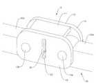
도 1은 본 발명에 따른 연동형 힌지의 예를 도시한 사시도.
도 2는 도 1에 도시된 연동형 힌지의 분해 사시도.
도 3은 암의 형태를 설명하기 위한 예시도로서, 암의 전면(a)과 후면(b)을 도시한 예시도.
도 4는 본 발명에 따른 암의 동기 회전을 설명하기 위한 예시도들.1 is a perspective view showing an example of an interlocking type hinge according to the present invention;
FIG. 2 is an exploded perspective view of the interlocking type hinge shown in FIG. 1; FIG.
Fig. 3 is an exemplary view for explaining the shape of the arm, showing an example of a front surface (a) and a rear surface (b) of the arm;
4 is an exemplary view for explaining the synchronous rotation of the arm according to the present invention;
이하, 본 발명의 바람직한 실시 예를 첨부한 도면을 참조하여 당해 분야의 통상의 지식을 가진 자가 용이하게 실시할 수 있도록 설명하기로 한다. 첨부된 도면들에서 구성에 표기된 도면번호는 다른 도면에서도 동일한 구성을 표기할 때에 가능한 한 동일한 도면번호를 사용하고 있음에 유의해야 한다. 또한, 본 발명을 설명함에 있어서 관련된 공지의 기능 또는 공지의 구성에 대한 구체적인 설명이 본 발명의 요지를 불필요하게 흐릴 수 있다고 판단되는 경우에는 그 상세한 설명을 생략하기로 한다. 그리고 도면에 제시된 어떤 특징들은 설명의 용이함을 위해 확대 또는 축소 또는 단순화된 것이고, 도면 및 그 구성요소들이 반드시 적절한 비율로 도시되어 있지는 않다. 그러나 당업자라면 이러한 상세 사항들을 쉽게 이해할 것이다.Hereinafter, preferred embodiments of the present invention will be described with reference to the accompanying drawings so that those skilled in the art can easily carry out the present invention. It should be noted that the drawings denoted by the same reference numerals in the drawings denote the same reference numerals whenever possible, in other drawings. In the following description of the present invention, a detailed description of known functions and configurations incorporated herein will be omitted when it may make the subject matter of the present invention rather unclear. And certain features shown in the drawings are to be enlarged or reduced or simplified for ease of explanation, and the drawings and their components are not necessarily drawn to scale. However, those skilled in the art will readily understand these details.
도 1은 본 발명에 따른 연동형 힌지의 예를 도시한 사시도이고, 도 2는 도 1에 도시된 연동형 힌지의 분해 사시도이다.FIG. 1 is a perspective view showing an example of an interlocking type hinge according to the present invention, and FIG. 2 is an exploded perspective view of the interlocking type hinge shown in FIG.
도 1 및 도 2를 참조하면 본 발명에 따른 연동형 힌지는 베이스블럭(9), 암(30) 및 탄성부재(40)을 포함하여 구성된다.Referring to FIGS. 1 and 2, the interlocking type hinge according to the present invention includes a
베이스 블럭(9)은 한 쌍으로 구성되는 암(30 : 30a, 30b)를 회동 가능하게 연결하며, 이를 통해 암(30)에 결합된 장치의 프레임(미도시)이 암(30)의 회전에 따라 펼쳐지거나 접혀지게 하는 역할을 한다. 이 베이스블럭(9)은 한 쌍의 암(30)이 이격되어 결합되고, 서로 연동되어 회전할 수 있게 한다. 특히, 이 베이스 블럭(9)은 암(30)의 회전시 회전 각도의 조절이 가능하도록 함과 아울러, 암(30)이 펼침과 접힘 상태를 유지할 수 있도록 탄성부재(40)가 수납된다.The
이를 위해 베이스 블럭(9)은 베이스(10)와 커버(15)를 포함하여 구성된다. 베이스(10)는 베이스면(12)과 베이스면(12)의 가장자리로부터 신장되어 형성되는 벽체(11)로 구성되고, 암(30)의 결합부위에 메인축(13)이 형성된다. 벽체(11)는 암(30)의 가동부위를 제외한 부분에 형성되며, 커버(15)와 베이스(10)의 간격을 유지하고, 내부에 탄성부재(40)를 고정하며, 커버(15)와 베이스(10)의 결합을 위해 형성된다.To this end, the
커버(15)는 도시된 바와 같이 베이스(10)와 결합되어 메인축(13)에 결합된 암(30)의 이탈을 방지하고 암(30)이 메인축(13)을 통해 회전 가능하게 하며, 내부에 탄성부재(40)가 수납 및 고정되도록 하는 역할을 한다. 베이스(10)와 커버(15)는 벽체(11)에 의해 이격되어 결합되며, 커버(15)에는 메인축(13)이 끼워지는 커버홀(17)이 형성된다. 여기서 커버홀(17)이 홀 형태로 형성되는 경우 메인축(13)이 커버홀(17)을 관통하여 노출되도록 하고 이를 고정하기 위한 고정수단을 구비할 수 있다. 또한 커버(15)에 커버홀(17)이 형성되지 않고, 커버(15)와 베이스(10)가 마주보는 면에 메인축(13)과 동상의 홈으로 형성될 수 있으나, 이하에서는 도면과의 일치를 위해 커버홀(17)이 형성된 것으로 가정하여 설명을 진행하기로 한다.The
이러한, 베이스(10)와 커버(15), 메인축(13)은 기계적으로 견고하고, 성형이 용이하며, 부식, 파손이 쉽게 생기지 않는 기계적, 화학적 특성이 우수한 합성수지, 금속과 같은 물질을 이용하여 형성될 수 있으나, 제시된 바에 의해서만 본 발명을 한정하는 것은 아니다.The
암(30)은 장치 프레임에 기계적으로 결합되고, 한 쌍으로 구성되어 베이스 블럭(9)에 회동가능하게 결합됨으로써 장치 프레임(미도시)의 접히거나 펼쳐지게 하는 역할을 한다. 이를 위해 암(30)은 한 쌍으로 구성되고, 각각이 메인축(13 : 13a, 13b)에 끼움결합되어 메인축(13)을 축으로 하여 회전하게 된다. 이러한 암(30)은 상호간에 슬라이딩축(20)과 슬라이딩암(21)에 의해 기계적으로 연결되어, 어느 한 쪽 암(30)의 움직임이 다른쪽 암(30)에 전달되도록 함으로써, 서로 동일한 회전 각도로 회전이 이루어지게 된다.The
특히, 암(30)은 탄성부(40)에 의해 가압되어 회전시 특정 각도를 유지하도록 하거나, 회전의 속도를 조절할 수 있게 되며, 이에 대해서는 하기에서 별도의 도면을 참조하여 좀 더 상세히 설명하기로 한다.In particular, the
암(30)의 종단에는 헤드(34 ; 34a, 34b)가 형성되며, 헤드(34)에는 메인축(13)과의 결합을 위한 축홀(33)이 형성된다. 그리고, 이 헤드(34)의 일측 모서리, 구체적으로 암(30)의 회전시 암(30) 간의 거리가 최소로 유지되는 모서리에는 결합부(39)가 형성된다. 결합부(39)에는 보조축(23)이 형성되고, 보조축(23)에는 슬라이딩암(21)이 회전 가능하게 결합된다.A
이 슬라이딩암(21)의 일측 종단은 보조축(23)에 회전가능하게 결합되고, 타측 종단은 슬라이딩축(20)에 회전가능하게 결합된다. 결합부(29)에 결합된 슬라이딩 암(21)은 슬라이딩축(20) 및 다른 암(30)의 슬라이딩암(21)을 통해 암(30)의 움직임을 전달하여, 한 쌍의 암(30a, 30b) 중 어느 하나의 움직임이 다른 암(30b, 30a)에 전달되도록 하고, 이를 통해 암(30a, 30b) 쌍의 움직임이 동기되어 이루어질 수 있게 하는 역할을 한다. 이때 슬라이딩축(20)은 전술한 바와 같이 가이드홀(16)을 따라 이동함으로써 슬라이딩암(21)가 함께 암 쌍(30a, 30b)의 회전을 동기시키는 역할을 하게 된다.One end of the sliding arm 21 is rotatably coupled to the
탄성부재(40)는 베이스블럭(9) 내부의 암 쌍(30a, 30b)의 사이에 배치되어 암쌍(30a, 30b)에 대해 탄성을 제공하고, 이를 통해 암(30a, 30b)의 회전각을 조절할 수 있게 하거나, 회전 속도를 조절하는 역할을 한다. 구체적으로 탄성부재(40)는 암(30)의 헤드(34)를 가압하며, 이때 헤드(34)에 형성되는 접촉면을 가압한다. 이를 통해 헤드(34)에 형성되는 접촉면의 형태에 따라 암(30)의 회전을 제약함으로써, 암이 접고 펼쳐지는 것뿐만 아니라, 접힘 상태와 펼침 상태의 중간 펼침 상태를 유지할 수 있게 하는 역할을 한다.The
이를 위해 탄성부재(40)는 암쌍(30a, 30b)을 가압하면서도 슬라이딩 축(20)의 움직임을 저해하지 않도록 'ㄷ' 자 형상으로 형성되고, 암(30)의 헤드(24)에 형성되는 접촉면의 가압이 유리하도록 회곡된 판상의 탄성체로 형성된다. 베이스(10)와 커버(15)에는 탄성부재(40)의 고정을 위한 구조물이 형성될 수 있으나, 다양한 형태로 형성이 가능하므로 이에 대한 상세한 설명은 생략하기로 한다. 아울러 탄성부재(40)에 의해 암(30)의 회전각 또는 회전속도를 조절하는 구성에 대해서는 하기의 도면을 참조하여 좀 더 상세히 설명하기로 한다.The
도 3은 암의 형태를 설명하기 위한 예시도로서, 암의 전면(a)과 후면(b)을 도시한 예시도이다.Fig. 3 is an exemplary view for explaining the shape of the arm, showing the front (a) and rear (b) of the arm.
도 3을 참조하면, 암(30)은 한 쌍으로 구성되며, 대를 이루어 베이스블럭(9)에 결합된다. 이러한 암(30)은 도시된 바와 같이 암(30a, 30b)의 일측종단에 헤드(34 : 34a, 34b)가 형성된다.Referring to FIG. 3, the
헤드(34)는 암(30)과 베이스블럭(9)을 결합시키는 결합부의 역할과, 탄성부재(40)와의 접촉에 의해 암(30)의 회전속도 또는 회전각을 조절하는 수단으로서의 역할을 수행한다.The
이를 위해 헤드(34)는 도시된 바와 같이 중앙부분에 축홀(33)이 형성되고, 이 축홀(33)에 메인축(13)이 끼워짐으로써 베이스 블럭(9)에 결합된다. 그리고 이 축홀(33)의 길이방향(또는 메인축과 나란한 방향)의 면에는 돌부(35)가 형성되며, 돌부(35)는 복수의 접촉면(36 내지 38)을 포함한다.To this end, the
돌부(35)는 탄성부재(40)에 의해 가압이 이루어지는 면으로, 회전에 따라 탄성부재(40)와 접촉되는 면이다. 탄성부재(40)는 이 접촉면을 가압함으로써, 암(30)이 펼침상태 또는 접힘상태 또는 펼침과 접힘의 중간상태를 유지할 수 있도록 암(30)을 가압하여 고정하게 된다. 서로 이웃하는 접촉면(36 내지 38)의 경계에는 모서리가 형성되는데, 암(30)이 회전하면서 탄성부재(40)와 모서리가 접촉하는 과정에서 탄성부재(40)가 오므려지게 되고, 다시 접촉면(36 내지 38)을 대하는 경우 복원되어 암(30)을 가압하여 고정하게 된다.The protruding portion 35 is a surface to be pressed by the
이 접촉면(36 내지 38)은 암(30)을 고정하고자하는 각도에 따라 복수의 면의 구성될 수 있다. 일례로 도 3에는 3개의 접촉면(36 내지 38)인 제1 내지 제3접촉면(36, 37, 38)로 구성된 예가 도시되어 있다. 우선, 펼침상태의 각을 유지하기 위해 암(30)의 길이방향 종단에 형성되는 제1접촉면(36), 제1접촉면(36)과 직각을 이루는 제2접촉면(37) 및 제1접촉면(36)과 제2접촉면(37)을 연결하는 경사면인 제3접촉면(38)으로 구성될 수 있다. 제1 및 제2암(30a, 30b)에 형성되는 제1접촉면(36)은 암(30)이 펼쳐진 상태에서 마주보며, 접힘상태에서 평행으로 이루게 된다. 또한, 제1 및 제2암(30a, 30b) 각각에 형성되는 제2접촉면(37)은 암(30)이 펼쳐진 상태에서 평행을 이루며, 접혀진 상태에서 마주 대하여 나란한 상태를 이루게 된다.The contact surfaces 36 to 38 may be formed of a plurality of surfaces depending on the angle at which the
즉, 탄성부재(40)는 암(30)의 회전에 따라 복수의 접촉면(36 내지 28) 중 서로 마주보는 상태의 접촉면(36 내지 38)을 가압하여, 외력이 가해지지 않는 한 암(30)이 회전하지 않고 현재의 각도를 유지하도록 가압하게 된다.That is, the
한편, 헤드(34)에는 결합부(39)가 형성된다. 결합부(39)는 슬라이딩암(21)과 결합기 위해 마련되며, 슬라이딩암(210의 회전을 보장하기 위해 헤드(34)의 일부분에 형성된다. 이 결합부(39)는 보조축923)이 형성되고, 보조축(23)에 슬라이딩암(21)의 일측 종단이 회전가능하게 결합된다.On the other hand, a
슬라이딩암(21)이 슬라이딩축(20)을 통해 다른 슬라이딩암(21)과 결합되기 때문에 결합부(29)의 위치는 헤드(34)의 종단 예를들어 제1접촉면(36)에 인접하여 구성되는 것이 베이스블럭(9)의 크기를 작게하면서도 암(30) 간의 회전이 연동되도록 할 수 있어 유리하지만, 제시된 바에 의해서만 본 발명을 한정하는 것은 아니다.Since the sliding arm 21 is coupled with the other sliding arm 21 through the sliding
일례로, 결합부(29)는 암(30)이 회전하는 경우 제1암(30a)과 제2암(30b)의 거리가 평균적으로 최소가 되는 위치는 즉, 제2접촉면(38)에 대응되는 위치나, 제1접촉면(36)과 제2접촉면(37) 사이의 모서리에 형성되도록 할 수 있다.For example, when the
도 4는 본 발명에 따른 암의 동기 회전을 설명하기 위한 예시도들이다.FIG. 4 is a view for explaining synchronous rotation of the arm according to the present invention. FIG.
도 4를 참조하면, 전술한 바와 같이 본 발명에 따른 힌지의 암(30)은 슬라이딩축(23)과 슬라이딩암(21), 그리고 가이드홀(16)에 의해 제1 및 제2암(30a, 30b)이 동일한 각도로 동기되어 회전하게 되고, 최종적으로 펼침 또는 접힘상태를 유지하게 된다.4, the
우선 (a)와 같은 펼침상태에서 제1암(30a)과 제2암(30b)는 길이방향으로 일직선인 상태를 유지하여 펼침상태가 되며, 이때, 슬라이딩축(20)은 가이드홀(16)의 하단(도면에서 아랫부분)으로 하강한 상태를 유지한다. 이는 제1암(30a)과 제2암(30b)이 펼침상태인경우 슬라이딩암(21)이 결합부(29)에 의해 당겨지게 되고, 이에 따라 슬라이딩축(23)이 슬라이딩암(21)을 따라 이동하게 되어 가이드홀(16)의 하단에 위치하게 된다. 이때, 탄성부재(40)는 제1접촉면(36)을 가압하여 제1암(30a)과 제2암(30b)이 펼침상태를 유지할 수 있게 한다.The first and
(b)와 같이 제1암(30a)과 제2암(30b)이 접히는 방향으로 회전하게 되면, 제1접촉면(36)에 의해 탄성부재(40)가 눌리게 되고, 이 눌림은 제1접촉면(36)과 제3접촉면(388)의 경계 모서리에서 극대화되며, 제3접촉면(38)과 접촉되면서 눌림이 줄어들어 복원된다. 그리고 제3접촉면(38)과 탄성부재(40)의 접촉면적이 최대화될 때, 탄성부재(40)의 복원도 최대화 되어, 탄성부재(40)가 제1암(30a)와 제2암(30b)를 가압하여 제3접촉면(38)과 접촉한 상태의 각도를 유지할 수 있게 한다.when the
이 과정에서 도시된 바와 같이 슬라이딩암(21)이 슬라이딩축(23)을 밀게 되고, 슬라이딩축(23)은 밀림에 의해 가이드홀(16)을 따라 이동하여 상승하게 된다. 이때, 슬라이딩축(23)의 이동은 슬라이딩암(21)과 가이드홀(16)에 의해 직선방향으로만 이동하게 되며, 동일한 슬라이딩암(21)의 길이로 인해 제1암(30a)와 제2암(30b)은 같은 각도로 회전하게 된다.The sliding arm 21 is pushed by the sliding
이때, 외력이 작용하여 접히는 각도로 계속 이동하게 되면 (b)에서 발생된 과정이 반복되어, 슬라이딩 축(23)은 가이드홀(21)의 최상단으로 인동하게 되어 제1암(30a)과 제2암(30b)이 서로 마주보는 평행상태 즉, 접힘이 이루어지게 된다.At this time, when the external force acts to continue to the folding angle, the process of (b) is repeated, so that the sliding
이러한 과정에서 탄성부재는 제3접촉면(38)과 제2접촉면(27) 및 이의 경계가 되는 모서리를 (a)에서 (b)로 넘어가는 과정에서와 같이 가압하게 되고, 접힘상태에서 제2접촉면(27)을 가압함으로써 제1암(30a)과 제2암(30b)이 접힘 상태를 유지할 수 있게 한다.In this process, the elastic member is pressurized as in the process of moving the
이와 같은 방법에 의해 돌부(35)에 복수의 접촉면을 형성하는 경우 접촉면의 수만큼 제1암(30a)과 제2암(30b) 사이의 각도를 조절하여 고정하는 것이 가능하게 된다.When a plurality of contact surfaces are formed on the protrusion 35 by this method, it is possible to adjust the angle between the
이러한 본 발명은 상기한 기재들에서와 같이 제1암(30a)과 제2암(30b)을 동일한 각도로 회전할 수 있도록 동기화시킬 수 있게 됨으로써, 상호 간의 각도 불일치에서 오는 문제점, 예를 들어, 플렉서블 디스플레이 장치의 표시패널 파손이 발생하는 일을 방지할 수 있게 된다.The present invention can synchronize the
이상에서 본 발명의 기술적 사상을 예시하기 위해 구체적인 실시 예로 도시하고 설명하였으나, 본 발명은 상기와 같이 구체적인 실시 예와 동일한 구성 및 작용에만 국한되지 않고, 여러 가지 변형이 본 발명의 범위를 벗어나지 않는 한도 내에서 실시될 수 있다. 따라서 그와 같은 변형도 본 발명의 범위에 속하는 것으로 간주해야 하며, 본 발명의 범위는 후술하는 특허청구범위에 의해 결정되어야 한다.While the present invention has been particularly shown and described with reference to exemplary embodiments thereof, it is to be understood that the invention is not limited to the disclosed exemplary embodiments, but, on the contrary, And the like. Accordingly, such modifications are deemed to be within the scope of the present invention, and the scope of the present invention should be determined by the following claims.
Claims (8)
Translated fromKorean일단에는 접힘/펼침 대상의 제1 프레임이 연결되고, 타단에는 상기 한 쌍의 메인축 중 어느 하나에 회전 가능하게 결합되도록 축홀이 형성되는 제1암;
일단에는 접힘/펼침 대상의 제2 프레임이 연결되고, 타단에는 상기 한 쌍의 메인축 중 나머지 하나에 회전 가능하게 결합되도록 축홀이 형성되는 제2암; 및
상기 베이스 블럭의 메인축을 기준으로 90도 범위에서 각각 회전하는 상기 제1 암과 상기 제2 암이 서로 연동 가능하게 결합되는 한 쌍의 슬라이딩암을 포함하고,
상기 한 쌍의 슬라이딩암 중 어느 하나의 슬라이딩 암은,
일측 종단이 제1암의 보조축에 회전 가능하게 결합되고, 타측 종단이 슬라이딩 축에 회전 가능하게 결합되고,
상기 한 쌍의 슬라이딩암 중 나머지 하나의 슬라이딩 암은,
일측 종단이 제2암의 보조축에 회전 가능하게 결합되고, 타측 종단이 상기 슬라이딩 축에 회전 가능하게 결합되며,
상기 슬라이딩 축은,
상기 제1암 및 상기 제2암의 회전에 따라 변동하는 상기 제1암의 보조축과 상기 제2암의 보조축 간의 이격 거리에 대응하여 상기 베이스 블럭에 형성된 가이드홈 또는 가이드홀을 따라 이동하는 연동형 힌지.A base block extending from the first surface and having a pair of main axes spaced apart from each other;
A first arm having a first frame connected at one end thereof with a first frame to be folded / unfolded and a shaft hole formed at the other end to be rotatably coupled to any one of the pair of main axes;
A second arm connected to a second frame of the folding / unfolding object at one end and having a shaft hole rotatably coupled to the other one of the pair of main shafts at the other end; And
And a pair of sliding arms that are coupled to each other so that the first arm and the second arm rotate in a range of 90 degrees with respect to the main axis of the base block,
Wherein one of the pair of sliding arms includes a sliding arm,
One end of which is rotatably coupled to the auxiliary shaft of the first arm and the other end of which is rotatably coupled to the sliding shaft,
The sliding arm of the other one of the pair of sliding arms,
One end of which is rotatably coupled to the auxiliary shaft of the second arm and the other end of which is rotatably coupled to the sliding shaft,
The sliding shaft
The first arm and the second arm move along a guide groove or a guide hole formed in the base block corresponding to a distance between a sub axis of the first arm and a sub axis of the second arm varying with rotation of the first arm and the second arm Interlocking hinge.
상기 가이드홈 또는 상기 가이드홀은
한 쌍의 상기 메인축을 잇는 가상의 선에 대해 수직인 방향으로, 일방향으로 길게 형성되는 것을 특징으로 하는 연동형 힌지.The method according to claim 1,
The guide groove or the guide hole
Wherein the hinge is elongated in one direction in a direction perpendicular to an imaginary line connecting a pair of the main axes.
한 쌍의 상기 메인축 사이에 배치되는 탄성부재를 더 포함하여 구성되는 것을 특징으로 하는 연동형 힌지.The method according to claim 1,
And an elastic member disposed between a pair of the main shafts.
상기 제1암 또는 상기 제2암은 상기 메인축과 결합되는 부위에 돌부를 가지는 헤드가 형성되고, 상기 탄성부재는 상기 돌부를 가압하는 것을 특징으로 하는 연동형 힌지.6. The method of claim 5,
Wherein the first arm or the second arm is formed with a head having a protrusion at a portion where the first arm or the second arm is coupled to the main shaft, and the elastic member presses the protrusion.
상기 돌부는 복수의 접촉면을 포함하고, 상기 탄성부재는 상기 제1암 및 상기 제2암의 회전각에 따라 상기 복수의 접촉면 중 어느 한 접촉면을 가압하는 것을 특징으로 하는 연동형 힌지.The method according to claim 6,
Wherein the protrusion includes a plurality of contact surfaces, and the elastic member presses one of the plurality of contact surfaces in accordance with the rotation angles of the first arm and the second arm.
Priority Applications (1)
| Application Number | Priority Date | Filing Date | Title |
|---|---|---|---|
| KR1020170027642AKR101901621B1 (en) | 2017-03-03 | 2017-03-03 | Coupled hinges and device using the same |
Applications Claiming Priority (1)
| Application Number | Priority Date | Filing Date | Title |
|---|---|---|---|
| KR1020170027642AKR101901621B1 (en) | 2017-03-03 | 2017-03-03 | Coupled hinges and device using the same |
Publications (2)
| Publication Number | Publication Date |
|---|---|
| KR20180100992A KR20180100992A (en) | 2018-09-12 |
| KR101901621B1true KR101901621B1 (en) | 2018-11-22 |
Family
ID=63592908
Family Applications (1)
| Application Number | Title | Priority Date | Filing Date |
|---|---|---|---|
| KR1020170027642AActiveKR101901621B1 (en) | 2017-03-03 | 2017-03-03 | Coupled hinges and device using the same |
Country Status (1)
| Country | Link |
|---|---|
| KR (1) | KR101901621B1 (en) |
Cited By (1)
| Publication number | Priority date | Publication date | Assignee | Title |
|---|---|---|---|---|
| KR20210009574A (en)* | 2019-07-17 | 2021-01-27 | 주식회사 파인테크닉스 | In-folding type flexible display |
Families Citing this family (2)
| Publication number | Priority date | Publication date | Assignee | Title |
|---|---|---|---|---|
| KR102328398B1 (en)* | 2018-10-25 | 2021-11-18 | 엘지전자 주식회사 | Flexible display device |
| WO2025084542A1 (en)* | 2023-10-16 | 2025-04-24 | 삼성전자 주식회사 | Hinge structure and portable electronic device comprising same |
Citations (1)
| Publication number | Priority date | Publication date | Assignee | Title |
|---|---|---|---|---|
| KR100944104B1 (en)* | 2008-12-03 | 2010-03-02 | 갤럭시아일렉트로닉스(주) | Angle control device and led electric light board with the same |
Family Cites Families (1)
| Publication number | Priority date | Publication date | Assignee | Title |
|---|---|---|---|---|
| KR102210047B1 (en) | 2014-03-05 | 2021-02-01 | 엘지디스플레이 주식회사 | Foldable display apparatus |
- 2017
- 2017-03-03KRKR1020170027642Apatent/KR101901621B1/enactiveActive
Patent Citations (1)
| Publication number | Priority date | Publication date | Assignee | Title |
|---|---|---|---|---|
| KR100944104B1 (en)* | 2008-12-03 | 2010-03-02 | 갤럭시아일렉트로닉스(주) | Angle control device and led electric light board with the same |
Cited By (2)
| Publication number | Priority date | Publication date | Assignee | Title |
|---|---|---|---|---|
| KR20210009574A (en)* | 2019-07-17 | 2021-01-27 | 주식회사 파인테크닉스 | In-folding type flexible display |
| KR102296241B1 (en) | 2019-07-17 | 2021-09-01 | 주식회사 파인테크닉스 | In-folding type flexible display |
Also Published As
| Publication number | Publication date |
|---|---|
| KR20180100992A (en) | 2018-09-12 |
Similar Documents
| Publication | Publication Date | Title |
|---|---|---|
| US11567540B2 (en) | Foldable device | |
| US20230185338A1 (en) | Foldable device | |
| KR101290267B1 (en) | Display device having variable display area | |
| CN106971673B (en) | A flexible display device | |
| KR102108151B1 (en) | Folding Hinge Apparatus and Electronic Device having it | |
| CN205858944U (en) | Rotatable connecting device applied to flexible display screen | |
| RU2481613C2 (en) | Tuckaway keyboard for portable computer | |
| CN108776508B (en) | display system | |
| WO2020156138A1 (en) | Rotary connecting assembly and folding terminal device | |
| KR101901621B1 (en) | Coupled hinges and device using the same | |
| KR20250123724A (en) | Folding type portable device having flexible display | |
| KR20190135159A (en) | Foldable Display Device | |
| CN103228114A (en) | Hinge module for flexible display device | |
| JP2022518987A (en) | Display folding type mobile terminal | |
| KR101754584B1 (en) | Flexible display module and one side folding apparatus with it | |
| CN211375464U (en) | Electronic device | |
| KR20240165395A (en) | Damping mechanism, hinge device and foldable electronic device | |
| CN211857984U (en) | Support structure and foldable display device | |
| US11720148B2 (en) | Portable electronic device having rollable display structure | |
| CN111899649A (en) | Support structure and foldable display device | |
| WO2020156142A1 (en) | Terminal device | |
| CN109618032B (en) | mobile terminal | |
| KR20170142597A (en) | Flexible display module and one side folding apparatus with it | |
| KR102317806B1 (en) | Foldable hinge apparatus | |
| KR102041498B1 (en) | Hinge module for flexible display |
Legal Events
| Date | Code | Title | Description |
|---|---|---|---|
| A201 | Request for examination | ||
| PA0109 | Patent application | St.27 status event code:A-0-1-A10-A12-nap-PA0109 | |
| PA0201 | Request for examination | St.27 status event code:A-1-2-D10-D11-exm-PA0201 | |
| E902 | Notification of reason for refusal | ||
| PE0902 | Notice of grounds for rejection | St.27 status event code:A-1-2-D10-D21-exm-PE0902 | |
| E13-X000 | Pre-grant limitation requested | St.27 status event code:A-2-3-E10-E13-lim-X000 | |
| P11-X000 | Amendment of application requested | St.27 status event code:A-2-2-P10-P11-nap-X000 | |
| P13-X000 | Application amended | St.27 status event code:A-2-2-P10-P13-nap-X000 | |
| PG1501 | Laying open of application | St.27 status event code:A-1-1-Q10-Q12-nap-PG1501 | |
| E701 | Decision to grant or registration of patent right | ||
| PE0701 | Decision of registration | St.27 status event code:A-1-2-D10-D22-exm-PE0701 | |
| GRNT | Written decision to grant | ||
| PR0701 | Registration of establishment | St.27 status event code:A-2-4-F10-F11-exm-PR0701 | |
| PR1002 | Payment of registration fee | St.27 status event code:A-2-2-U10-U11-oth-PR1002 Fee payment year number:1 | |
| PG1601 | Publication of registration | St.27 status event code:A-4-4-Q10-Q13-nap-PG1601 | |
| PR1001 | Payment of annual fee | St.27 status event code:A-4-4-U10-U11-oth-PR1001 Fee payment year number:4 | |
| PR1001 | Payment of annual fee | St.27 status event code:A-4-4-U10-U11-oth-PR1001 Fee payment year number:5 | |
| R18-X000 | Changes to party contact information recorded | St.27 status event code:A-5-5-R10-R18-oth-X000 | |
| PR1001 | Payment of annual fee | St.27 status event code:A-4-4-U10-U11-oth-PR1001 Fee payment year number:6 | |
| PR1001 | Payment of annual fee | St.27 status event code:A-4-4-U10-U11-oth-PR1001 Fee payment year number:7 | |
| PR1001 | Payment of annual fee | St.27 status event code:A-4-4-U10-U11-oth-PR1001 Fee payment year number:8 |