KR101898291B1 - Multi-touch and multi-user detecting device - Google Patents
Multi-touch and multi-user detecting deviceDownload PDFInfo
- Publication number
- KR101898291B1 KR101898291B1KR1020120040288AKR20120040288AKR101898291B1KR 101898291 B1KR101898291 B1KR 101898291B1KR 1020120040288 AKR1020120040288 AKR 1020120040288AKR 20120040288 AKR20120040288 AKR 20120040288AKR 101898291 B1KR101898291 B1KR 101898291B1
- Authority
- KR
- South Korea
- Prior art keywords
- user
- touch
- indicating
- circuit
- signal
- Prior art date
- Legal status (The legal status is an assumption and is not a legal conclusion. Google has not performed a legal analysis and makes no representation as to the accuracy of the status listed.)
- Active
Links
Images


Classifications
- G—PHYSICS
- G06—COMPUTING OR CALCULATING; COUNTING
- G06F—ELECTRIC DIGITAL DATA PROCESSING
- G06F3/00—Input arrangements for transferring data to be processed into a form capable of being handled by the computer; Output arrangements for transferring data from processing unit to output unit, e.g. interface arrangements
- G06F3/01—Input arrangements or combined input and output arrangements for interaction between user and computer
- G06F3/03—Arrangements for converting the position or the displacement of a member into a coded form
- G06F3/041—Digitisers, e.g. for touch screens or touch pads, characterised by the transducing means
- G06F3/044—Digitisers, e.g. for touch screens or touch pads, characterised by the transducing means by capacitive means
- G06F3/0446—Digitisers, e.g. for touch screens or touch pads, characterised by the transducing means by capacitive means using a grid-like structure of electrodes in at least two directions, e.g. using row and column electrodes
- G—PHYSICS
- G06—COMPUTING OR CALCULATING; COUNTING
- G06F—ELECTRIC DIGITAL DATA PROCESSING
- G06F3/00—Input arrangements for transferring data to be processed into a form capable of being handled by the computer; Output arrangements for transferring data from processing unit to output unit, e.g. interface arrangements
- G06F3/01—Input arrangements or combined input and output arrangements for interaction between user and computer
- G06F3/03—Arrangements for converting the position or the displacement of a member into a coded form
- G06F3/041—Digitisers, e.g. for touch screens or touch pads, characterised by the transducing means
- G06F3/0412—Digitisers structurally integrated in a display
- G—PHYSICS
- G06—COMPUTING OR CALCULATING; COUNTING
- G06F—ELECTRIC DIGITAL DATA PROCESSING
- G06F3/00—Input arrangements for transferring data to be processed into a form capable of being handled by the computer; Output arrangements for transferring data from processing unit to output unit, e.g. interface arrangements
- G06F3/01—Input arrangements or combined input and output arrangements for interaction between user and computer
- G06F3/03—Arrangements for converting the position or the displacement of a member into a coded form
- G06F3/041—Digitisers, e.g. for touch screens or touch pads, characterised by the transducing means
- G—PHYSICS
- G01—MEASURING; TESTING
- G01R—MEASURING ELECTRIC VARIABLES; MEASURING MAGNETIC VARIABLES
- G01R27/00—Arrangements for measuring resistance, reactance, impedance, or electric characteristics derived therefrom
- G01R27/02—Measuring real or complex resistance, reactance, impedance, or other two-pole characteristics derived therefrom, e.g. time constant
- G01R27/26—Measuring inductance or capacitance; Measuring quality factor, e.g. by using the resonance method; Measuring loss factor; Measuring dielectric constants ; Measuring impedance or related variables
- G01R27/2605—Measuring capacitance
- G—PHYSICS
- G01—MEASURING; TESTING
- G01R—MEASURING ELECTRIC VARIABLES; MEASURING MAGNETIC VARIABLES
- G01R27/00—Arrangements for measuring resistance, reactance, impedance, or electric characteristics derived therefrom
- G01R27/02—Measuring real or complex resistance, reactance, impedance, or other two-pole characteristics derived therefrom, e.g. time constant
- G01R27/26—Measuring inductance or capacitance; Measuring quality factor, e.g. by using the resonance method; Measuring loss factor; Measuring dielectric constants ; Measuring impedance or related variables
- G01R27/2611—Measuring inductance
- G—PHYSICS
- G06—COMPUTING OR CALCULATING; COUNTING
- G06F—ELECTRIC DIGITAL DATA PROCESSING
- G06F3/00—Input arrangements for transferring data to be processed into a form capable of being handled by the computer; Output arrangements for transferring data from processing unit to output unit, e.g. interface arrangements
- G06F3/01—Input arrangements or combined input and output arrangements for interaction between user and computer
- G06F3/03—Arrangements for converting the position or the displacement of a member into a coded form
- G06F3/041—Digitisers, e.g. for touch screens or touch pads, characterised by the transducing means
- G06F3/0416—Control or interface arrangements specially adapted for digitisers
- G—PHYSICS
- G06—COMPUTING OR CALCULATING; COUNTING
- G06F—ELECTRIC DIGITAL DATA PROCESSING
- G06F3/00—Input arrangements for transferring data to be processed into a form capable of being handled by the computer; Output arrangements for transferring data from processing unit to output unit, e.g. interface arrangements
- G06F3/01—Input arrangements or combined input and output arrangements for interaction between user and computer
- G06F3/03—Arrangements for converting the position or the displacement of a member into a coded form
- G06F3/041—Digitisers, e.g. for touch screens or touch pads, characterised by the transducing means
- G06F3/045—Digitisers, e.g. for touch screens or touch pads, characterised by the transducing means using resistive elements, e.g. a single continuous surface or two parallel surfaces put in contact
- G—PHYSICS
- G06—COMPUTING OR CALCULATING; COUNTING
- G06F—ELECTRIC DIGITAL DATA PROCESSING
- G06F3/00—Input arrangements for transferring data to be processed into a form capable of being handled by the computer; Output arrangements for transferring data from processing unit to output unit, e.g. interface arrangements
- G06F3/01—Input arrangements or combined input and output arrangements for interaction between user and computer
- G06F3/03—Arrangements for converting the position or the displacement of a member into a coded form
- G06F3/041—Digitisers, e.g. for touch screens or touch pads, characterised by the transducing means
- G06F3/046—Digitisers, e.g. for touch screens or touch pads, characterised by the transducing means by electromagnetic means
- G—PHYSICS
- G06—COMPUTING OR CALCULATING; COUNTING
- G06F—ELECTRIC DIGITAL DATA PROCESSING
- G06F3/00—Input arrangements for transferring data to be processed into a form capable of being handled by the computer; Output arrangements for transferring data from processing unit to output unit, e.g. interface arrangements
- G06F3/01—Input arrangements or combined input and output arrangements for interaction between user and computer
- G06F3/048—Interaction techniques based on graphical user interfaces [GUI]
- G06F3/0487—Interaction techniques based on graphical user interfaces [GUI] using specific features provided by the input device, e.g. functions controlled by the rotation of a mouse with dual sensing arrangements, or of the nature of the input device, e.g. tap gestures based on pressure sensed by a digitiser
- G06F3/0488—Interaction techniques based on graphical user interfaces [GUI] using specific features provided by the input device, e.g. functions controlled by the rotation of a mouse with dual sensing arrangements, or of the nature of the input device, e.g. tap gestures based on pressure sensed by a digitiser using a touch-screen or digitiser, e.g. input of commands through traced gestures
- G—PHYSICS
- G06—COMPUTING OR CALCULATING; COUNTING
- G06F—ELECTRIC DIGITAL DATA PROCESSING
- G06F2203/00—Indexing scheme relating to G06F3/00 - G06F3/048
- G06F2203/041—Indexing scheme relating to G06F3/041 - G06F3/045
- G06F2203/04104—Multi-touch detection in digitiser, i.e. details about the simultaneous detection of a plurality of touching locations, e.g. multiple fingers or pen and finger
Landscapes
- Engineering & Computer Science (AREA)
- General Engineering & Computer Science (AREA)
- Theoretical Computer Science (AREA)
- Physics & Mathematics (AREA)
- General Physics & Mathematics (AREA)
- Human Computer Interaction (AREA)
- Electromagnetism (AREA)
- Position Input By Displaying (AREA)
- User Interface Of Digital Computer (AREA)
- Electronic Switches (AREA)
Abstract
Translated fromKoreanDescription
Translated fromKorean본 발명은 복수의 유저가 펜이나 손가락 등의 복수의 지시체(摯示體)를 이용하여 동시에 정보의 입력을 가능하게 하기 위해서, 당해 복수의 지시체가 근접 또는 접촉하는 위치의 각각을, 유저마다 검출 가능한 멀티 터치·멀티 유저 검출 장치에 관한 것이다.In order to allow a plurality of users to input information at the same time using a plurality of indicating objects such as a pen or a finger, each position of the plurality of indicating objects is approximated or contacted is detected for each user And a multi-touch multi-user detecting device.
터치 패널 등의 지시체 검출 장치가 넓게 이용되게 되어, 지시체 검출 장치에 관한 다양한 발명이 이루어지고 있다. 본원의 발명자 등은 먼저, 손가락 등의 복수의 지시체에 의한 복수의 지시 위치의 검출(다점 검출)을 가능하게 한 크로스 포인트형 정전 결합 방식의 지시체 검출 장치에 관한 발명을 행하여, 본원의 출원인에 의해서 이미 출원되어 있다.A pointing device detecting device such as a touch panel is widely used, and various inventions concerning the pointing device detecting device have been made. The inventors of the present application first carried out the invention relating to a pointing type electrostatic coupling type indicating body detecting device capable of detecting a plurality of pointing positions (multi-point detecting) by a plurality of pointing bodies such as fingers, Have already been filed.
도 11의 지시체 검출 장치(1X)는 크로스 포인트형 정전 결합 방식의 지시체 검출 장치의 구성예를 나타내고 있다. 지시체 검출 장치(1X)는 센서부(100)를 가지고 있다. 당해 센서부(100)는 하층측으로부터 순서대로 송신 도체군(11), 절연층, 수신 도체군(12)을 적층하여 형성된 것이다. 송신 도체군(11)은 도 11에 있어서, X축 방향으로 연장한 선(線) 모양의 복수의 송신 도체(11Y1, 11Y2, …)를 서로 소정 간극 이격시켜 병렬 배치한 것이다. 또, 수신 도체군(12)은 송신 도체(11Y1, 11Y2, …)에 대해서 교차하는 방향(도 11의 Y축 방향)으로 연장한 선 모양의 복수의 수신 도체(12X1, 12X2, …)를 서로 소정 간극 이격시켜 병렬 배치한 것이다.The indicator detection device 1X in Fig. 11 shows a configuration example of a cross point type electrostatic coupling type indicator detection device. The indicator detecting device 1X has a sensor unit 100. [ The sensor unit 100 is formed by laminating the
지시체 검출 장치(1X)에서는 송신 신호 공급 회로(21)가 제어 회로(40)의 제어에 따라서, 클럭 신호 발생 회로(22)로부터의 클럭 신호에 따른 타이밍으로, 송신 도체(11Y1, 11Y2, …)의 각각에 다른 소정 신호를 공급한다. 구체적으로, 송신 신호 공급 회로(21)는 송신 도체마다 다른 주파수 신호를 공급하거나(주파수 다중 방식), 소정의 부호화 패턴의 신호로부터 송신 도체마다 위상 시프트시킨 신호를 생성해 공급하거나(위상 시프트 방식), 송신 도체마다 다른 부호 패턴의 신호를 공급하거나(부호 다중 방식) 할 수 있는 것이다.In the indicator device 1X, the transmission
그리고 수신부(300)에 있어서, 송신 도체(11Y1, 11Y2, …) 각각과 수신 도체(12X1, 12X2, …) 각각과의 교차점(크로스 포인트)에 흐르는 전류의 변화를 각 크로스 포인트에서 검출한다. 이 경우, 센서부(100) 위에 있어서, 손가락 등의 지시체가 놓여진 위치에서는, 전류가 지시체를 통해서 분류됨으로써 전류가 변화한다. 이 때문에, 전류가 변화하는 크로스 포인트를 검출함으로써, 지시체에 의해 지시된 센서부(100) 위의 위치를 검출할 수 있는 것이다.In the
구체적으로, 수신부(300)에 있어서는, 도 11에 도시된 바와 같이, 각 수신 도체(12X1, 12X2, …)의 신호를 증폭 회로(31)에서 증폭하고, A/D 변환 회로(32)에서 디지털 신호로 변환하여 연산 처리 회로(33)에 공급한다. 연산 처리 회로(33)는 제어부(40)의 제어에 따라서 A/D 변환 회로(32)로부터의 디지털 신호에 대해, 송신 도체(11Y1, 11Y2, …) 각각에 공급된 소정 신호에 따른 연산 처리를 행하므로써, 각 크로스 포인트에서의 전류 변화를 검출한다.11, the amplifying
예를 들면, 송신 신호 공급 회로(21)가 주파수 다중 방식의 것이면, 연산 처리 회로(33)는 송신 신호 공급 회로(21)로부터 각 송신 도체(11Y1, 11Y2, …)에 공급된 신호와 동일한 주파수 신호를 이용한 동기 검파 연산을 행함으로써, 목적으로 하는 주파수 신호를 검출한다. 이 목적으로 하는 주파수 신호의 레벨에 따라서, 위치 검출 회로(34)가 제어부(40)의 제어에 따라서 동작하여 지시체에 의한 지시 위치가 검출된다.For example, if the transmission
또, 송신 신호 공급 회로(21)가 위상 시프트 방식이나 부호 다중 방식의 것이면, 연산 처리 회로(33)는 송신 신호 공급 회로(21)로부터 각 송신 도체(11Y1, 11Y2, …)에 공급된 부호에 대응한 부호를 이용한 상관 연산을 행함으로써, 목적으로 하는 부호에 대응한 상관 연산값을 산출한다. 위치 검출 회로(34)는 제어부(40)의 제어에 따라서 동작하고, 산출된 상관 연산값에 기초하여 지시체에 의한 지시 위치가 검출된다.If the transmission
그리고 크로스 포인트형 정전 결합 방식의 지시체 검출 장치의 경우, 상술한 것처럼, 센서부(100) 위에 복수의 크로스 포인트가 마련되는 구성을 가지므로, 복수의 지시체에 의한 지시 위치의 검출(다점 검출)이 가능해진다.In the case of the pointing device of the cross-point type electrostatic coupling type, since a plurality of cross points are provided on the sensor unit 100 as described above, the detection of the pointed position by the plurality of pointing devices It becomes possible.
또한, 주파수 다중 방식을 이용한 크로스 포인트형 정전 결합 방식의 지시체 검출 장치에 대한 발명은, 후에 기재하는 특허 문헌 1에 개시되어 있고, 위상 시프트 방식을 이용한 크로스 포인트형 정전 결합 방식의 지시체 검출 장치에 대한 발명은, 후에 기재하는 특허 문헌 2에 개시되어 있다. 또, 부호 다중 방식을 이용한 크로스 포인트형 정전 결합 방식의 지시체 검출 장치에 대한 발명은 2009년 12월 18일자로 출원한 특원 2009-288273의 출원 서류에 기재되어 있다.The invention of a cross point type electrostatic coupling type indicator indicating apparatus using a frequency multiplexing method is disclosed in
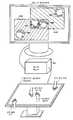
또, 후에 기재하는 특허 문헌 3 및 특허 문헌 4에는 복수의 유저가 동시에 터치 표면에 접촉한 경우에, 유저마다의 터치 표면 위의 접촉 위치를 검출하는 멀티 유저 터치 시스템에 관한 발명이 개시되어 있다. 예를 들면, 인용 문헌 3에 기재된 멀티 유저 터치 시스템은, 도 12에 도시된 바와 같이, 디스플레이 유니트(T200), 투명 기판(410), 접촉 검출 엘리먼트(420), 투명 도전층(450), 전극(EA~ED)을 구비한 테이블형의 것이다. 또한, 도 12에는 도시하지 않았지만, 투명 도전층(450)에는 소정 신호를 투명 도전층(450)에 공급하는 송신기가 접속되고, 또 테이블 탑(T100) 위의 4개 전극(EA~ED) 각각에는, 각각마다 수신기가 접속되어 있다.Patent Literature 3 and Patent Document 4 described later disclose an invention related to a multi-user touch system that detects a contact position on a touch surface for each user when a plurality of users touch the touch surface at the same time. 12, the multi-user touch system described in Reference Document 3 includes a display unit T200, a transparent substrate 410, a contact detection element 420, a transparent conductive layer 450, (EA to ED). Although not shown in FIG. 12, a transmitter for supplying a predetermined signal to the transparent conductive layer 450 is connected to the transparent conductive layer 450, and four electrodes EA to ED on the table top T100 A receiver is connected to each of them.
그리고 도 12에 도시된 바와 같이, 유저(UA, UB) 각각이 한쪽 손의 손가락을 디스플레이 유니트(T200)의 표시 화면 위의 투명 도전층(450)에 접촉시킴과 아울러, 다른 쪽 손의 손가락을 자신 가까이에 있는 전극(EA, EB)에 접촉시킨다. 이 경우, 투명 도전층(450)에 접속된 송신기로부터의 신호가, 당해 투명 도전층(450) 및 유저(UA, UB)의 신체를 통해서, 전극(EA, EB)에 공급되어 추가로 전극(EA, EB)의 각각에 접속된 수신기에 공급된다.12, each of the users UA and UB touches the finger of one hand to the transparent conductive layer 450 on the display screen of the display unit T200, and the finger of the other hand To contact the electrodes (EA, EB) near themselves. In this case, a signal from the transmitter connected to the transparent conductive layer 450 is supplied to the electrodes EA and EB via the body of the transparent conductive layer 450 and the users UA and UB, EA, EB).
이것에 의해, 전극(EA~ED) 각각마다 미리 유저를 할당해 둠으로써, 전극 (EA~EB) 각각에 접속된 수신기의 수신 결과에 기초하여 어느 유저가 디스플레이 유니트의 표시 화면 위의 투명 도전층(450)에 손가락 등을 접촉시키고 있는지를 검지할 수 있다. 또한, 접촉 검출 엘리먼트(420)를 통해서 접촉 검출 엘리먼트상의 유저의 접촉 위치도 검출할 수 있다.Thus, by assigning users to each of the electrodes EA to ED in advance, it is possible to determine which user is the transparent conductive layer on the display screen of the display unit, based on the reception result of the receiver connected to each of the electrodes EA to EB, It is possible to detect whether or not a finger or the like is brought into contact with the finger 450. The contact position of the user on the contact detection element can also be detected through the contact detection element 420. [
또, 이것과는 반대의 구성으로 할 수도 있다. 즉, 전극(EA~ED) 각각마다 다른 신호를 발생시키는 송신기를 접속하고, 투명 도전층(450)에는 수신기를 접속해 두도록 한다. 그리고 도 12에 도시된 것처럼, 유저(UA, UB) 각각이 한쪽 손의 손가락을 자신 가까이에 있는 전극(EA, EB)에 접촉시킴과 아울러, 다른 쪽 손의 손가락을 디스플레이 유니트(T200)의 표시 화면 위의 투명 도전층(450)에 접촉시킨다. 이 경우, 전극(EA)에 접속된 송신기로부터의 신호가 유저(UA)의 신체를 통해서 투명 도전층(450)에 공급되고, 추가로 투명 도전층을 통해서 수신기에 공급된다. 마찬가지로, 전극(EB)에 접속된 송신기로부터의 신호가 유저(UB)의 신체를 통해서 투명 도전층(450)에 공급되고, 추가로 투명 도전층을 통해서 수신기에 공급된다.It is also possible to adopt a configuration opposite to this. That is, a transmitter that generates different signals for each of the electrodes EA to ED is connected, and a receiver is connected to the transparent conductive layer 450. 12, each of the users UA and UB is brought into contact with the electrodes EA and EB near one finger of the one hand and the finger of the other hand is brought into contact with the display of the display unit T200 And is brought into contact with the transparent conductive layer 450 on the screen. In this case, a signal from a transmitter connected to the electrode EA is supplied to the transparent conductive layer 450 through the body of the user UA, and further supplied to the receiver through the transparent conductive layer. Similarly, a signal from the transmitter connected to the electrode EB is supplied to the transparent conductive layer 450 through the body of the user UB, and further supplied to the receiver through the transparent conductive layer.
이것에 의해, 이 경우에는 접촉 검출 엘리먼트(420)를 통해서 유저(UA, UB)의 접촉 위치를 검출할 수 있다. 그리고 각 전극(EA~ED)의 각각에 접속된 송신기마다 미리 유저를 할당해 둠으로써, 투명 도전층(450)을 통해서 수신기가 수신한 신호에 따라서, 어느 유저가 디스플레이 유니트의 표시 화면 위의 투명 도전층(450)에 손가락 등을 접촉시키고 있는지를 검지할 수 있게 된다.Thus, in this case, the contact position of the users UA and UB can be detected through the contact detection element 420. [ By assigning a user in advance to each transmitter connected to each of the electrodes EA to ED, a user can be transparently displayed on the display screen of the display unit in accordance with a signal received by the receiver through the transparent conductive layer 450 It is possible to detect whether or not a finger or the like is brought into contact with the conductive layer 450.
최근에, 터치 패널 등의 지시체 검출 장치와 비교적 큰 표시 화면을 가지는 디스플레이 장치를 조합시킴으로써, 종래에 없는 전자 칠판이나 게임기 등을 실현하는 것이 생각되고 있다. 이와 같은 전자 칠판이나 게임기의 경우, 보다 유연한 조작성을 실현함과 아울러 조작과 표시의 공조도 유연하게 실시하도록 하는 것이 바람직하다.Recently, it has been considered to realize an electronic blackboard, a game machine, and the like which are not conventionally used by combining a pointing device detecting device such as a touch panel and a display device having a relatively large display screen. In the case of such an electronic board or a game machine, it is preferable to realize more flexible operability and to smoothly perform the operation and the display.
이를 위해서, 우선, 복수의 유저가 복수의 지시체를 이용하여 동시에 터치 패널 등의 지시체 검출 장치의 센서부 위의 위치를 지시하도록 한 경우에, 유저마다 그 지시 위치 각각을 파악할 수 있도록 하는 것이 바람직하다. 또한, 각 유저를 위한 각 지시 위치에, 표시시키는 정보를 제어할 수 있는 등의 것도 바람직하다.To this end, it is preferable that a plurality of users simultaneously use the plurality of indicating bodies to indicate the position on the sensor portion of the indicating body detecting device such as a touch panel at the same time, so that each of the directing positions can be grasped for each user . It is also preferable that information to be displayed can be controlled at each indication position for each user.
그렇지만, 상술한 특허 문헌 1, 2 등에 기재된 크로스 포인트형 정전 결합 방식을 이용한 지시체 검출 장치 발명의 경우에는, 복수의 유저에 의한 동시 사용을 상정하고 있지 않기 때문에, 다점 검출은 할 수 있어도, 유저 판별까지는 할 수 없다. 또, 상술한 특허 문헌 3, 4에 기재된 멀티 유저 터치 시스템 발명의 경우에는, 복수의 유저가 동시에 복수의 지시체를 이용하는 것을 상정하고 있지 않기 때문에, 유저의 검출은 할 수 있어도, 유저마다의 다점 검출(멀티 터치의 검출)을 행하는 것은 할 수 없거나, 또는 유저마다의 다점 검출(멀티 터치의 검출)을 높은 정밀도로 행할 수 없는 것이다.However, in the case of the invention of the pointing device using the cross-point type electrostatic coupling system described in the above-mentioned
우선, 특허 문헌 3에 기재된 멀티 유저 터치 시스템 발명의 경우, 유저의 한쪽 손은 테이블 탑(T100) 위에 마련된 전극(EA~ED) 중 어느 하나에 접촉시켜야만 하기 때문에, 양손을 이용한 조작 입력을 행할 수 없다. 따라서 유연한 조작성을 실현한다고 하는 관점에서는 어려움이 있다.First, in the case of the multi-user touch system disclosed in Patent Document 3, since one hand of the user must be in contact with any one of the electrodes EA to ED provided on the table top T100, none. Therefore, it is difficult from the viewpoint of realizing flexible operability.
또, 전술한 특허 문헌 4에 기재된 멀티 유저 터치 시스템 발명의 경우에는, 단락 [0025]에 기재되어 있는 것처럼, 유저에 의한 각 지시 위치 지시의 타이밍 정보도 고려하지 않으면, 유저마다의 다점 검출은 할 수 없다. 이 경우, 당해 타이밍 정보를 정확하게 취득할 수 없으면, 유저마다의 다점 검출의 검출 정밀도가 저하해 버린다고 하는 문제가 있다.In addition, in the case of the multi-user touch system invention described in the above-mentioned Patent Document 4, as described in paragraph [0025], if the timing information of each instruction position instruction by the user is not taken into consideration, I can not. In this case, if the timing information can not be accurately obtained, there is a problem that the detection accuracy of multipoint detection for each user is lowered.
따라서 다점 검출이 가능한 특허 문헌 1, 2에 기재된 기술과 멀티 유저 검출이 가능한 특허 문헌 3, 4에 기재된 기술을 간단하게 조합시킨다 하더라도, 구성이 복잡하게 될 뿐, 다점 검출(멀티 터치의 검출)과 유저의 검출(멀티 유저의 검출) 양쪽 모두를 높은 정밀도로 행할 수 없다. 이 때문에, 복수의 유저 각각이 복수의 손가락 등의 지시체를 이용하여 동시에 조작한 경우, 유저마다의 조작과 표시를 공조시키는 것도 어렵다.Therefore, even if the techniques described in
이상의 것을 감안하여, 본 발명은 복수의 유저가 복수의 지시체를 이용하여 동시에 조작한 경우더라도, 다점 검출(멀티 터치의 검출)과 유저의 검출(멀티 유저의 검출) 양쪽 모두를 높은 정밀도로 행할 수 있도록 함과 아울러, 조작과 표시의 공조도 유연하게 행할 수 있도록 하는 것을 목적으로 한다.In view of the above, the present invention is capable of performing both multi-point detection (multi-touch detection) and user detection (multi-user detection) with high accuracy even when a plurality of users simultaneously operate using a plurality of directors The present invention also aims to make it possible to flexibly perform an operation and a display.
상기 과제를 해결하기 위해, 본 발명의 제1 실시 형태에 의한 멀티 터치·멀티 유저 검출 장치는 제1 방향으로 배치된 복수의 제1 도체와, 상기 제1 방향에 대해서 교차하는 제2 방향으로 배치된 복수의 제2 도체로 이루어진 센서 도체와, 상기 제1 방향으로 배치된 복수의 제1 도체에 소정 신호를 공급하기 위한 신호 송신 회로와, 상기 제2 방향으로 배치된 복수의 제2 도체로부터의 신호를 수신하는 신호 수신 회로와, 상기 신호 수신 회로로부터 출력된 신호에 기초하여, 상기 센서 도체에 대해서 복수의 지시체가 지시하는 위치를 검출하는 지시 위치 검출 회로와, 상기 센서 도체로부터의 신호를 수신하고, 상기 신호 송신 회로에 의해서 상기 제1 방향으로 배치된 복수의 제1 도체에 공급되는 신호와는 식별 가능한 지시체 식별 정보를 검출하는 제1 지시체 식별 정보 검출 회로와, 상기 지시 위치 검출 회로로부터 출력된 위치 정보와 상기 제1 지시체 식별 정보 검출 회로로부터 출력된 지시체 식별 정보에 기초하여, 복수의 지시체에 의해서 지시된 위치가 어느 지시체에 의한 지시인지의 대응 관계를 특정하기 위한 대응 관계 특정 회로를 구비함으로써, 상기 센서 도체에 대해서 상기 복수의 지시체가 지시하는 각각의 위치와 상기 복수의 지시체의 대응 관계를 특정할 수 있도록 한 것을 특징으로 한다.According to a first aspect of the present invention, there is provided a multi-touch multi-user detecting apparatus including a plurality of first conductors arranged in a first direction and a plurality of second conductors arranged in a second direction crossing the first direction A signal transmission circuit for supplying a predetermined signal to a plurality of first conductors arranged in the first direction, and a signal transmission circuit for supplying a predetermined signal from the plurality of second conductors arranged in the second direction An instruction position detecting circuit for detecting a position indicated by a plurality of indicating bodies with respect to the sensor conductor based on a signal outputted from the signal receiving circuit; And a first indicating body for detecting the indicating body identification information distinguishable from the signal supplied to the plurality of first conductors arranged in the first direction by the signal transmitting circuit, Based on the positional information outputted from the indicated position detection circuit and the indicator identification information outputted from the first indicator-identification-information detection circuit, whether the position indicated by the plurality of indicators is the indicator And a correspondence relation specifying circuit for specifying a correspondence relationship between the plurality of indicating objects and the plurality of indicating objects to be specified by the plurality of indicating objects with respect to the sensor conductor.
이 본 발명의 제1 실시 형태에 의한 멀티 터치·멀티 유저 검출 장치에 의하면, 센서 도체는 복수의 제1 도체와 복수의 제2 도체가 교차하도록 배치되어 복수의 제1 도체와 복수의 제2 도체에 의해 복수의 교차점(크로스 포인트)이 형성된다. 복수의 제1 도체와 복수의 제2 도체는 정전 결합하고 있어, 복수의 제1 도체에 신호 송신 회로로부터의 소정 신호가 공급되면, 이것에 따라서 제2 도체에 신호가 유기되어 이 신호가 신호 수신 회로에 의해 수신된다.According to the multi-touch multi-user detection apparatus of the first embodiment of the present invention, the sensor conductor is arranged so that the plurality of first conductors and the plurality of second conductors cross each other, and the plurality of first conductors and the plurality of second conductors A plurality of intersection points (cross points) are formed. A plurality of first conductors and a plurality of second conductors are electrostatically coupled to each other. When a predetermined signal is supplied from a signal transmission circuit to a plurality of first conductors, a signal is induced to the second conductor according to the predetermined signal, Circuit.
그리고 신호 수신 회로로부터의 신호에 기초하여, 지시 위치 검출 회로에 의해, 센서 도체에 대해서 복수의 지시체 각각이 지시하는 위치가 검출된다. 또, 센서 도체로부터의 신호에 기초하여, 신호 송신 회로에 의해 제1 도체에 공급되는 신호와는 식별 가능한 지시체 식별 정보가 지시체 식별 정보 검출 회로에 의해 검출된다. 그리고 지시 위치 검출 회로로부터의 위치 정보와 지시체 식별 정보 검출 회로로부터의 지시체 식별 정보에 기초하여, 대응 관계 특정 회로에 의해 복수의 지시체가 지시하는 각각의 위치와 지시체의 대응 관계가 특정된다.Based on the signal from the signal receiving circuit, the indicated position detecting circuit detects the position indicated by each of the plurality of indicating bodies with respect to the sensor conductor. Also, on the basis of the signal from the sensor conductor, the indicating body identification information which can be distinguished from the signal supplied to the first conductor by the signal transmitting circuit is detected by the indicating body identifying information detecting circuit. Based on the positional information from the indicated position detecting circuit and the indicating body identification information from the indicating body identifying information detecting circuit, the correspondence relationship between each position indicated by the plurality of indicating bodies and the indicating body is specified by the corresponding relationship specifying circuit.
이것에 의해, 복수의 지시체에 의해서 지시된 각각의 위치 검출(멀티 터치의 검출)과 각 지시체를 이용한 유저의 검출(멀티 유저의 검출)의 양쪽 모두를, 복잡한 처리를 행하는 일 없이, 간단하고 또한 높은 정밀도로 행할 수 있게 된다.Thereby, both of the position detection (multi-touch detection) indicated by the plurality of indicating bodies and the detection of the user using each indicating body (multi-user detecting) can be performed simply and without complicated processing And can be performed with high accuracy.
본 발명에 의하면, 복수의 유저가 복수의 지시체를 이용하여 동시에 조작한 경우더라도, 다점 검출(멀티 터치의 검출)과 유저의 검출(멀티 유저의 검출)의 양쪽 모두를 높은 정밀도로 행할 수 있다. 이것에 의해, 조작과 표시의 공조도 유연하게 행할 수 있다.According to the present invention, even when a plurality of users simultaneously operate using a plurality of indicating bodies, it is possible to perform both the multi-point detection (multi-touch detection) and the user detection (multi-user detection) with high precision. Thereby, it is possible to flexibly perform the cooperation between the operation and the display.
도 1은 본 발명의 일 실시 형태가 적용되어 구성된 멀티 터치·멀티 유저 검출 장치의 개요에 대해서 설명하기 위한 도면이다.
도 2는 실시 형태의 멀티 터치·멀티 유저 검출 장치(1)의 구성예를 설명하기 위한 블록도이다.
도 3은 도 2에 도시된 멀티 터치·멀티 유저 검출 장치(1)의 유저 및 위치 식별 회로(33A)의 구성예를 설명하기 위한 블록도이다.
도 4는 멀티 터치·멀티 유저 검출 장치(1)가 이용되어 형성된 정보 처리 장치의 이용 양태의 일례를 설명하기 위한 도면이다.
도 5는 유저 조작 영역간의 입력 정보의 카피 처리를 설명하기 위한 도면이다.
도 6은 유저(A,B) 각각의 유저 조작 영역의 일부가 중복하도록 된 경우에 대해서 설명하기 위한 도면이다.
도 7은 멀티 터치·멀티 유저 검출 장치와 디스플레이 장치를 별체(別體)로 한 정보 처리 장치의 예를 설명하기 위한 도면이다.
도 8은 멀티 유저의 검출을 행하는 회로 부분을 마련하는 개소(箇所)에 대한 변형예를 설명하기 위한 블록도이다.
도 9는 수신부(300A)와 Y축 방향 유저 ID 검출부(500)를 가지는 멀티 터치·멀티 유저 검출 장치의 경우의 각 부의 동작 기간을 설명하기 위한 도면이다.
도 10은 신호 발생기(2)의 실시 양태를 설명하기 위한 도면이다.
도 11은 크로스 포인트형 정전 결합 방식의 지시체 검출 장치의 종래의 구성예를 나타내는 블록도이다.
도 12는 종래의 멀티 유저 터치 시스템의 예를 설명하기 위한 도면이다.Fig. 1 is a diagram for explaining an outline of a multi-touch multi-user detecting apparatus configured by applying one embodiment of the present invention.
Fig. 2 is a block diagram for explaining a configuration example of the multi-touch multi-user detecting
Fig. 3 is a block diagram for explaining a configuration example of the user and
Fig. 4 is a view for explaining an example of the use of the information processing apparatus formed by using the multi-touch multi-user detecting
5 is a diagram for explaining copy processing of input information between user operation areas.
6 is a diagram for explaining a case where a part of the user operation area of each of the users A and B is made to overlap.
7 is a diagram for explaining an example of an information processing apparatus in which a multi-touch multi-user detecting apparatus and a display apparatus are separately provided.
Fig. 8 is a block diagram for explaining a modified example of a portion where a circuit portion for detecting a multi-user is provided.
9 is a diagram for explaining the operation period of each part in the case of a multi-touch multi-user detecting device having a receiving
Fig. 10 is a diagram for explaining an embodiment of the signal generator 2. Fig.
11 is a block diagram showing a conventional configuration example of a cross point type electrostatic coupling type indicator indicating device.
12 is a diagram for explaining an example of a conventional multi-user touch system.
이하, 도면을 참조하면서, 본 발명에 의한 멀티 터치·멀티 유저 검출 장치의 일 실시 형태에 대해서 설명한다.Hereinafter, an embodiment of a multi-touch multi-user detecting device according to the present invention will be described with reference to the drawings.
[멀티 터치·멀티 유저 검출 장치의 개요][Outline of multi-touch multi-user detection device]
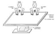
도 1은 본 발명의 일 실시 형태가 적용되어 구성된 멀티 터치·멀티 유저 검출 장치의 개요에 대해서 설명하기 위한 도면이다. 도 1에 도시된 바와 같이, 이 실시 형태의 멀티 터치·멀티 유저 검출 장치(1)는 디스플레이 장치(3)의 표시 화면 위에 적층되도록 배치되고, 디스플레이 장치(3)와 일체가 되어서 이용되도록 된다.Fig. 1 is a diagram for explaining an outline of a multi-touch multi-user detecting apparatus configured by applying one embodiment of the present invention. As shown in Fig. 1, the multi-touch multi-user detecting
즉, 멀티 터치·멀티 유저 검출 장치(1)의 조작면과 디스플레이 장치(3)의 표시 화면은 그 크기, 형상이 거의 일치하고 있는 것이다. 그리고 멀티 터치·멀티 유저 검출 장치(1)의 조작면 위의 위치와 디스플레이 장치(3)의 표시 화면 위의 위치는 1대1로 대응하게 되어 있다.That is, the operation surface of the multi-touch
이 때문에, 멀티 터치·멀티 유저 검출 장치(1)는 투과성을 가지고, 멀티 터치·멀티 유저 검출 장치(1)를 통해서 디스플레이 장치(3)의 표시 화면에 표시된 화상을 높은 시인성(視認性)으로 관시(觀視)할 수 있게 되어 있다. 또한, 디스플레이 장치(3)는 LCD(Liquid Crystal Display), 유기 EL 디스플레이(organic electroluminescence display), PDP(Plasma Display Panel) 등의 박(薄)형 표시 소자가 적용될 수 있다. 또, CRT(cathode Ray Tube)를 이용할 수도 있다.Therefore, the multi-touch
또, 멀티 터치·멀티 유저 검출 장치(1)와 디스플레이 장치(3)는 표시 제어 장치(4)에 접속된다. 이 표시 제어 장치(4)는 컴퓨터 장치이며, 멀티 터치·멀티 유저 검출 장치(1)로부터의 검출 출력에 따라서, 디스플레이 장치(3)의 표시 화면에 표시하는 표시 정보나 표시 양태를 제어한다.In addition, the multi-touch multi-user detecting
이와 같이, 이 실시 형태에 있어서는, 도 1에 도시된 것처럼, 멀티 터치·멀티 유저 검출 장치(1)와, 디스플레이 장치(3)와, 표시 제어 장치(4)에 의해, 이른바 테이블형의 구성으로 된 정보 처리 장치를 형성하고 있다.1, the multi-touch
그리고 이 실시 형태의 멀티 터치·멀티 유저 검출 장치(1)는 자세한 것은 후술하지만, 크로스 포인트형 정전 결합 방식을 채용함으로써 다점 검출(멀티 터치의 검출)을 행할 수 있는 것이다. 상술한 것처럼, 크로스 포인트형 정전 결합 방식에는 주파수 다중 방식과, 위상 시프트 방식과, 부호 다중 방식 등이 있다. 이 실시 형태에 있어서 설명을 간단하게 하기 위해서, 송신 도체마다 다른 주파수 신호를 공급하는 주파수 다중 방식을 이용하는 경우를 예로서 설명한다.The multi-touch
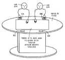
또한, 이 실시 형태의 멀티 터치·멀티 유저 검출 장치(1)는 도 1에 있어서 유저(A,B)가 동시에 지시 조작을 행하고 있는 경우를 나타내고 있는 것처럼, 복수의 유저로부터의 지시 조작을 동시에 수신하는 것이 가능한, 비교적으로 넓은 조작 영역을 가지는 것이다. 이 때문에, 이 실시 형태의 멀티 터치·멀티 유저 검출 장치(1)에 있어서는, 복수의 유저가 동시에 지시 조작을 행한 경우더라도, 각 지시 위치가 어느 유저에 의해서 지시되었는지의 검출(멀티 유저의 검출)도 할 수 있도록 하고 있다.The multi-touch
구체적으로, 멀티 유저의 검출을 실현하기 위해서, 멀티 터치·멀티 유저 검출 장치(1)에 대해서 지시 조작을 실행하는 유저 각각은, 유저마다 고유 신호를 발생시키는 신호 발생기를 몸에 부착하고 있다. 도 1에 있어서는, 유저(A)는 신호 발생기(2A)를 몸에 부착하고, 유저(B)는 신호 발생기(2B)를 몸에 부착하고 있는 경우를 나타내고 있다. 그리고 신호 발생기(2A,2B)로부터의 신호가 유저(A,B)의 신체 및 지시체를 통해서 멀티 터치·멀티 유저 검출 장치(1)에 공급됨으로써, 지시체에 의해 지시된 지시 위치가 어느 유저에 의해서 지시되었는지의 식별(검출)이 행해진다.Specifically, in order to realize multi-user detection, each user who performs the instruction operation with respect to the multi-touch
유저가 사용하는 신호 발생기(2A,2B)도, 또, 유저마다 다른 주파수 신호를 출력하거나, 유저마다 다른 부호 패턴의 신호를 출력하거나 하는 것으로서 실현된다. 또한, 이 실시 형태에 대한 설명을 간단하게 하기 위하여, 신호 발생기(2A,2B)는 유저마다 다른 주파수 신호를 출력하는 것인 경우를 예로서 설명한다.The
단, 이 실시 형태의 멀티 터치·멀티 유저 검출 장치(1)는 상술한 것처럼, 멀티 터치의 검출도 실현되는 것이다. 이 때문에, 주파수 다중 방식을 채용하는 경우에는, 신호 발생기(2A,2B) 각각은 멀티 터치·멀티 유저 검출 장치(1)의 복수의 송신 도체 각각에 공급되는 송신 신호와는 다른 주파수 신호로서, 또한 유저마다 다른 주파수 신호를 출력하는 것이다.However, as described above, the multi-touch multi-user detecting
또한, 유저가 이용하는 각각의 신호 발생기(2A,2B)는 기본적으로 서로 같은 구성을 가지는 것이다. 이 때문에, 이하에 있어서는 특히 구별하여 나타내는 경우를 제외하고, 유저가 이용하는 신호 발생기(2A,2B)를 총칭하여 신호 발생기(2)라고 한다. 또, 신호 발생기(2)는 발진기에 의해서 목적으로 하는 주파수 신호를 발신시키고, 목적으로 하는 전압 레벨까지 승압하여 유저의 신체로 전반(傳搬) 가능한 여러 가지의 구성을 채용할 수 있다.Each of the
이와 같이, 이 실시 형태의 멀티 터치·멀티 유저 검출 장치(1)는 다점 검출(멀티 터치의 검출)과 동시에, 각 지시 위치는 어느 유저에 의해서 지시된 것인지에 대한 검출(멀티 유저의 검출)도 행할 수 있는 것이다. 그리고 상술한 것처럼, 멀티 터치·멀티 유저 검출 장치(1)로부터의 검출 출력에 기초하여, 표시 제어 장치(4)가 디스플레이 장치(3)의 표시 화면에 표시하는 표시 정보나 표시 양태를 제어할 수 있도록 하고 있다.As described above, the multi-touch
또한, 멀티 터치·멀티 유저 검출 장치(1)에 대해서 지시 조작을 행하는 지시체는 유저의 손가락 등 외에, 유저마다 1이상의 터치 펜을 이용하는 것도 가능하다. 그러나 이 실시 형태에 있어서는, 설명을 간단하게 하기 위해서, 지시체는 유저의 손가락인 경우를 예로서 설명한다.It is also possible to use at least one touch pen for each user in addition to the user's finger or the like as a pointing device for performing the pointing operation with respect to the multi-touch multi-user detecting
[멀티 터치·멀티 유저 검출 장치(1)의 구성예][Configuration Example of Multi-Touch Multi-User Detection Apparatus 1]
다음으로, 멀티 터치·멀티 유저 검출 장치(1)의 구성예에 대해서 설명한다. 도 2는 이 실시 형태의 멀티 터치·멀티 유저 검출 장치(1)의 구성예를 설명하기 위한 블록도이다. 도 2에 도시된 바와 같이, 이 실시 형태의 멀티 터치·멀티 유저 검출 장치(1)는 터치 센서(검출 센서)를 구비하는 센서부(100)와, 송신부(200)와, 수신부(300A)와, 이러한 동작을 제어하는 제어부(40)로 이루어진다. 제어 회로(40)는 이 실시 형태의 멀티 터치·멀티 유저 검출 장치(1)의 각 부를 제어하기 위한 회로이며, 예를 들면 마이크로 컴퓨터를 탑재하여 구성되어 있다.Next, a configuration example of the multi-touch
센서부(100)는 도 11에 도시된 종래의 크로스 포인트형 정전 결합 방식의 지시체 검출 장치의 센서부(100)와 같게 구성되는 부분이다. 즉, 센서부(100)는 송신부(200)에 접속되는 복수의 제1 도체와, 수신부(300A)에 접속되는 복수의 제2 도체를 구비한다. 이하의 설명에서는, 예를 들면 64개의 송신 도체(11Y1~11Y64)로 이루어진 제1 도체가 송신 도체이며, 송신 도체군(11)을 구성한다. 또, 예를 들면, 64개의 수신 도체(12X1~12X64)로 이루어진 제2 도체는 수신 도체이며, 수신 도체군(12)을 구성한다. 또한, 송신 도체군(11)을 구성하는 송신 도체의 개수, 수신 도체군(12)을 구성하는 수신 도체의 개수, 배열 간격 등은 지시 입력면(100S)의 사이즈 등 실시 양태에 따라서 적당하게 설정된다.The sensor unit 100 is the same as the sensor unit 100 of the prior art cross point type electrostatic coupling type indicator device shown in FIG. That is, the sensor unit 100 includes a plurality of first conductors connected to the transmitting
송신 도체군(11)을 구성하는 64개의 송신 도체 각각은, 센서부(100)의 X축 방향(도 2의 횡방향)으로 연장하여 배치된 직선 모양의 도체이다. 수신 도체군(12)을 구성하는 64개의 수신 도체 각각은, 센서부(100)의 Y축 방향(도 2의 종방향)으로 연장하여 배치된 직선 모양의 도체이다. 송신 도체군(11)과 수신 도체군(12)은 절연재를 사이에 두고 대향 배치되어 있다. 송신 도체와 수신 도체가 교차하는 점이 크로스 포인트로 칭해진다.Each of the 64 transmission conductors constituting the
송신 도체(11Y) 및 수신 도체(12X)는, 예를 들면 은패턴이나 ITO(Indium Tin Oxide:산화 인듐 주석) 막으로 이루어진 투명 전극막 또는 동박 등으로 형성된다. 또한, 도시하지 않았지만, 이 예의 센서부(100)는 하측으로부터 순서대로(Z축 방향으로), 하측 기판, 송신 도체군(11), 절연재, 수신 도체군(12), 상측 기판의 순서대로 적층되어 형성되어 있다. 또, 하측 기판 및 상측 기판은, 예를 들면 투명한 합성 수지 등으로 이루어진 시트 모양(필름 모양)의 것 또는 유리 기판이나 동박 패턴 기판으로 구성된다.The
수신 도체군(12)측(상측 기판측)이, 도 2에 도시된 것처럼, 유저에 의해서 손가락 등의 지시체가 이용되어 지시 조작 입력이 행해지는 지시 입력면(100S)으로 된다. 그리고 이 실시 형태의 멀티 터치·멀티 유저 검출 장치(1)는 도 1에 도시된 것처럼, 예를 들면 액정 패널 등의 디스플레이 장치(3)와 일체 구성된다. 이 경우, 멀티 터치·멀티 유저 검출 장치(1)의 센서부(100)가 디스플레이 장치(3)의 표시 화면 위에 겹쳐서 마련된다.As shown in Fig. 2, the receiving conductor group 12 side (upper substrate side) serves as an
송신부(200)도 또, 도 11에 도시된 종래의 크로스 포인트형 정전 결합 방식의 지시체 검출 장치의 송신부(200)와 같게 구성되는 부분이다. 즉, 송신부(200)는 센서부(100)의 지시 입력면(100S)에 대한 지시체에 의한 지시 위치의 검출을 가능하게 하기 위한 신호를, 송신 도체군(11)의 각 송신 도체에 공급한다. 송신부(200)는 도 2에 도시된 것처럼, 송신 신호 공급 회로(21)와 클럭 발생 회로(22)를 구비하고 있다. 송신 신호 공급 회로(21)는 제어부(40)로부터의 제어에 따라서, 클럭 발생 회로(22)로부터의 클럭 신호 CLK의 타이밍으로, 송신 도체(11Y1~11Y64) 각각에 대해서 다른 주파수 신호(주기 신호)를 동시 공급(다중 송신)한다. 이와 같은 신호의 공급 형태를 「주파수 다중 방식」이라고 칭하고, 공급되는 복수의 주기 신호를 총칭하여 「다주파 신호」라고 한다.The transmitting
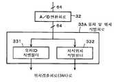
수신부(300A)는 수신 도체군(12)을 구성하는 각 수신 도체로부터 얻어진 수신 신호(전류 신호)에 대해서 신호 처리를 함으로써, 지시체에 의한 지시 입력면(100S) 위의 지시 위치의 검출(식별)과, 지시체 마다의 유저 검출(식별)을 행하기 위한 것이다. 그리고 수신부(300A)는, 도 2에 도시된 바와 같이, 증폭 회로(31)와, A/D(Analog/Digital) 변환 회로(32)와, 유저 및 위치 식별 회로(33A)와, 위치 검출 회로(34A)를 구비하고 있다.The receiving
증폭 회로(31)는 수신 도체군을 구성하는 각 수신 도체로부터 얻어진 수신 신호를 증폭하여 A/D 변환 회로(32)에 공급하는 것이다. A/D 변환 회로(32)는 증폭 회로(31)에 있어서 증폭된 각 수신 도체로부터의 수신 신호를 디지털 신호로 변환하여, 이것들을 유저 및 위치 식별 회로(33A)에 공급하는 것이다.The
유저 및 위치 식별 회로(33A)는 센서부(100)에 대해서 지시체를 이용하여 지시 조작이 행해진 경우에, 지시체에 의해 지시된 지시 위치의 검출(식별)과 각 지시 위치를 지시한 유저의 검출(식별)을 행한다. 이 경우, 손가락 등의 복수의 지시체가 동시에 이용된 경우에는, 복수의 지시체 각각의 지시 위치를 식별할 수 있고, 또, 복수의 유저가 동시에 지시 조작을 행한 경우에는, 각 지시 위치는 어느 유저에 의해서 지시되었는지를 식별할 수 있도록 하고 있다. 즉, 유저 및 위치 식별 회로(33A)는 멀티 터치의 검출과 멀티 유저의 검출 양쪽 모두를 실현하는 것이다.The user and
도 3은 유저 및 위치 식별 회로(33A)의 구성예를 설명하기 위한 블록도이다. 도 3에 도시된 바와 같이, 유저 및 위치 식별 회로(33A)는 각 수신 도체에 대해서, 유저 ID 식별 필터(331)와 지시 위치 식별 필터(332)가 마련된 것이다. 그리고 유저 ID 식별 필터(331)가 멀티 유저의 검출을 실현하는 부분이고, 지시 위치 식별 필터(332)가 멀티 터치의 검출을 실현하는 부분이다.3 is a block diagram for explaining a configuration example of the user and
유저 ID 식별 필터(331)는 A/D 변환 회로(32)를 통해서 공급되는 각 수신 도체로부터의 디지털화된 수신 신호 각각에 대해서, 각 유저가 구비하는 신호 발생기(2)로부터의 신호와 동일한 주파수 신호를 이용하여 동기 검파 연산을 행한다. 이것에 의해서, 지시 조작을 행한 유저가 있을 때는, 지시체를 이용하여 지시 조작을 행한 유저를 유저 ID 식별 필터(331)를 통해서 수신 도체마다 식별(검출)할 수 있다.The user
구체적으로는, 유저 ID 식별 필터(331)는 수신 도체마다 DCT 연산을 이용한 동기 검파 처리를 행한 연산 회로가, 동시에 조작이 가능하게 되는 유저의 수만큼 병렬로 마련된다. 각 연산 회로에는 유저마다 주파수가 다르게 되는 신호 발생기(2)로 발생시키는 신호와 동일한 주파수 신호가 1대1로 대응하도록 할당된다.Concretely, the user
그리고 유저 ID 식별 필터(331)에 병렬로 마련되는 각 연산 회로 각각에서는 디지털 신호에 변환된 소정의 수신 도체로부터의 신호에 대해서, 자신의 회로에 할당된 소정의 주파수 신호를 곱셈하여 적분한다. 이 경우에, 각 연산 회로 각각은, 예를 들면, 당해 소정의 주파수 신호가 존재하는 경우에는 하이 레벨이 되고, 존재하지 않는 경우에는 로우 레벨이 되는 신호를 출력한다. 이것에 의해, 각 연산 회로에 있어서 자신의 회로에 할당된 주파수 신호를 검출할 수 있었던 경우에는, 처리 대상 신호의 공급원의 수신 도체에 대해서, 그 주파수 신호를 발생시키고 있는 신호 발생기(2)를 이용하고 있는 유저가 지시체를 이용하여 지시 입력을 행하고 있는 것으로 판별할 수 있다.Each of the arithmetic circuits provided in parallel to the user
이와 같이, 이 실시 형태에 있어서, 유저가 구비하는 신호 발생기(2)로부터의 신호의 주파수가 유저를 식별하기 위한 ID 정보가 되어 있다. 그리고 유저 ID 식별 필터(331)는 상술한 것처럼, 어느 수신 도체에 대해서 어느 유저가 지시체를 이용하여 지시 입력을 행하고 있는지를 나타내는 정보를 출력할 수 있도록 되어 있다.Thus, in this embodiment, the frequency of the signal from the signal generator 2 provided by the user is ID information for identifying the user. As described above, the user
한편, 지시 위치 식별 필터(332)는 A/D 변환 회로(32)를 통해서 공급되는 각 수신 도체로부터의 디지털화된 수신 신호의 각각에 대해서, 송신 도체군(11)의 각 송신 도체에 공급된 신호와 동일한 주파수 신호를 이용한 동기 검파 연산을 행한다. 이것에 의해, 지시 위치 식별 필터(332)는 각 크로스 포인트에 있어서의 전류 변화를 검출한다. 또한, 이 전류 변화는 전압의 변화로 변환하여 검출할 수도 있다.On the other hand, for each of the digitized reception signals from the respective reception conductors supplied through the A /
구체적으로는, 지시 위치 식별 필터(332)는 수신 도체마다, DCT 연산을 이용한 동기 검파 처리를 행한 연산 회로가 송신 도체의 수와 동일한 64개 마련된다. 그리고 수신 도체마다 마련되는 각 연산 회로에는 송신 도체마다 주파수가 다르도록 되는 각 송신 도체에 공급된 신호와 동일한 주파수 신호가 1대1로 대응하도록 할당된다.Specifically, the indicated
이와 같이, 지시 위치 식별 필터(332)에는 64개의 수신 도체마다 64개의 송신 도체에 대응하여 64개의 연산 회로가 마련된다. 다시 말하면, 지시 위치 식별 필터(332)에 마련되는 각 연산 회로는 지시 입력면(100S) 위의 64개×64개의 크로스 포인트에 대응하도록 마련되어 있다.As described above, the indicating
그리고 지시 위치 식별 필터(332)에 있어서, 수신 도체마다 마련되는 64개의 연산 회로 각각에 있어서는, 대응하는 수신 도체로부터의 디지털 신호로 된 신호에 대해서, 자신의 회로에 할당된 소정의 주파수 신호를 곱셈하여 적분한다. 이것에 의해, 수신 도체마다 마련되는 64개의 연산 회로의 각각에 있어서, 수신 신호의 공급원인 수신 도체와 각 송신 도체가 형성하는 크로스 포인트에 있어서의 전류 변화가 검출된다.In each of the 64 arithmetic circuits provided for each receiving conductor in the pointing
상술한 것처럼, 송신 도체군(11)의 각 송신 도체에는, 송신 신호 공급 회로(21)에 의해 송신 도체마다 다른 주파수 신호가 공급되고 있다. 따라서 지시체인 유저의 손가락이 센서부(100)의 지시 입력면(100S)에 접촉 또는 근접하면, 이웃하는 크로스 포인트에서는 송신 도체로부터의 송신 신호가 지시체로도 흘러들어, 송신 도체로부터 수신 도체로 흘러드는 전류가 감소한다.As described above, a frequency signal different for each transmission conductor is supplied to each of the transmission conductors of the
이 때문에, 지시 위치 식별 필터(332)에 있어서, 각 크로스 포인트로 대응하여 마련되는 연산 회로는, 대응하는 크로스 포인트에 지시체가 접촉 또는 근접하고 있는 경우에는 지시체가 접촉도 근접도 하고 있지 않는 통상 레벨보다도 낮은 레벨의 검출 신호를 출력한다. 이것에 의해, 지시 위치 식별 필터(332)의 각 연산 회로로부터의 검출 출력에 기초하여, 지시체가 접촉 또는 근접하고 있는 크로스 포인트를 식별(검출)할 수 있다. 그리고 크로스 포인트는 상술한 것처럼 수신 도체와 송신 도체의 교차점이므로, 지시 입력면(100S) 위에 있어서의 지시체의 접촉 위치 또는 근접 위치를, 지시 입력면(100S) 위의 크로스 포인트에서 파악할 수 있다.For this reason, in the instruction
이와 같이, 지시 위치 식별 필터(332)는 지시 입력면(100S) 위의 어느 크로스 포인트에 대해서 지시체에 의해 지시 조작이 행해지고 있는지를 나타내는 정보를 출력할 수 있게 된다.As described above, the indicated
그리고 수신부(300A)의 위치 검출 회로(34A)는 유저 ID 식별 필터(331)로부터의, 어느 수신 도체에 대해서 어느 유저가 지시체를 이용하여 지시 입력을 행하고 있는지를 나타내는 정보의 제공을 받는다. 또, 위치 검출 회로(34A)는 지시 위치 식별 필터(332)로부터 지시 입력면(100S) 위의 어느 크로스 포인트에 대해서 지시체에 의해 지시 조작이 행해지고 있는지를 나타내는 정보의 제공을 받는다.The
위치 검출 회로(34A)는 유저 ID 식별 필터(331)로부터의 정보와 지시 위치 식별 필터(332)로부터의 정보에 기초하여 1이상의 지시체에 의한 지시 위치 각각을 검출함과 아울러, 각 지시 위치는 어느 유저에 의해서 지시되었는지를 검출하여 출력한다. 즉, 위치 검출 회로(34A)는 지시 입력면(100S) 위의 지시체에 의한 지시 위치를 나타내는 2차원 좌표 데이터(X축 데이터와 Y축 데이터)와 유저 식별 정보가 대응지어진 정보를 출력한다.The
구체적으로는, 예를 들면, 도 2에 나타낸 것처럼, 센서부(100) 위의 수신 도체(12X6)와 송신 도체(11Y61)가 교차하는 크로스 포인트에, 유저(A)가 손가락(지시체)을 접촉시키고 있었다고 한다. 이 경우, 상술한 지시 위치 식별 필터(332)의 기능에 의해, 수신 도체(12X6)와 송신 도체(11Y61)가 교차하는 크로스 포인트가 지시체에 의해 지시받고 있는 것이 식별된다. 동시에, 상술한 유저 ID 식별 필터(331)의 기능에 의해, 수신 도체(12X6)를 유저(A)가 지시체에 의해 지시하고 있는 것이 식별된다. 이러한 식별 결과는 수신 도체(12X)에 의해 대응지을(묶을)수 있다.Specifically, for example, as shown in Figure 2, the cross-point sensor section 100, reception conductor (12X6) and the transmission conductor (11Y61) above the crossing, the user (A) is a finger (pointing device) . In this case, it is identified that the cross point at which the
따라서 이 예의 경우, 위치 검출 회로(34A)는 지시체의 지시 위치를 나타내는 2차원 좌표 데이터(수신 도체(12X6), 송신 도체(11Y61))와 유저 식별 정보(유저(A)의 유저 ID)를 대응지은, 예를 들면, (수신 도체(12X6), 송신 도체(11Y61), 유저(A))라는 정보를 형성하여 출력한다. 그리고 복수의 유저가 양쪽 손의 5개 손가락의 모두를 지시체로서 이용하고, 센서부(100)에 대해서 지시 조작을 행하여도, 유저 및 위치 식별 회로(33A)의 기능에 의해, 지시체마다 그 지시 위치(크로스 포인트)와 그 지시체를 사용한 유저를 파악할 수 있다. 이 때문에, 위치 검출 회로(34A)는 지시체마다 지시체의 지시 위치를 나타내는 2차원 좌표 데이터와 유저 식별 정보를 대응지은 정보를 형성하여 출력할 수 있다. 또, 유저(B)의 손가락이 센서부(100) 위의 위치를 지시하고 있던 경우에도, 마찬가지로 하여 지시체의 지시 위치를 나타내는 2차원 좌표 데이터와 유저 식별 정보를 대응지은 정보를 출력할 수 있다.As a result, (the user ID of the user (A)) For this example, the position detection circuit (34A) is a two-dimensional coordinate data indicating the pointed position of the pointing device (reception conductor (12X6), the transmission conductor (11Y61)) and identify the user information the corresponding built, for example, and outputs the form information of (reception conductor (12X6), the transmission conductor (11Y61), the user (a)). Even if a plurality of users use all of the five fingers of both hands as a pointing member and perform an instruction operation on the sensor unit 100, the function of the user and the
위치 검출 회로(34A)로부터의 출력 정보는, 도 1에 도시된 표시 제어 장치(4)에 공급된다. 이것에 의해, 표시 제어 장치(4)는 이하에 구체적으로 설명하는 것처럼, 유저마다의 지시 위치에 따른 디스플레이 장치(3)의 표시 화면 위의 대응하는 위치에, 각 유저를 식별 가능한 양태로 정보를 표시하는 등을 할 수 있게 된다.The output information from the
[멀티 터치·멀티 유저 검출 장치(1)를 가지는 정보 처리 장치의 이용 양태][Usage of Information Processing Apparatus Having Multi-Touch Multi-User Detection Apparatus 1]
다음으로, 이 실시 형태의 멀티 터치·멀티 유저 검출 장치(1)가 이용되어 형성된 도 1에 도시된 정보 처리 장치의 이용 양태에 대해서 구체적으로 설명한다.Next, the use of the information processing apparatus shown in Fig. 1 in which the multi-touch multi-user detecting
도 4는 이 실시 형태의 멀티 터치·멀티 유저 검출 장치(1)가 이용되어 형성된 정보 처리 장치의 이용 양태의 일 예를 설명하기 위한 도면이고, 멀티 터치·멀티 유저 검출 장치(1)의 지시 입력면(조작면: 100S)의 상방에서 보았을 경우를 나타내고 있다. 도 4에 도시된 예에 있어서는, 유저(A,B)는 멀티 터치·멀티 유저 검출 장치(1)의 지시 입력면(100S)을 사이에 두고, 비스듬하게 서로 마주 보도록 위치하고 있다.Fig. 4 is a view for explaining an example of the usage of the information processing apparatus formed by using the multi-touch multi-user detecting
그리고 도 4에 도시된 바와 같이, 유저(A,B) 각각이, 소정의 사각형의 대각선상의 2점을 지시하도록, 지시 입력면(100S)에 대해서 자기의 양손을 접촉 또는 근접시키도록 했다고 한다. 멀티 터치·멀티 유저 검출 장치(1)는 상술한 것처럼, 멀티 터치의 검출과 멀티 유저의 검출을 행하고, 그 검출 출력을 표시 제어 장치(4)에 대해서 공급한다.As shown in Fig. 4, it is assumed that each of the users A and B is brought into contact with or close to both hands of the
이와 같이, 지시 입력면(100S)에 대해서, 유저가 대각선상의 2점을 동시에 지시하는 조작이 행해진 경우에는, 표시 제어 장치(4)는 유저 조작 영역의 설정 지시가 행해졌다고 판별한다. 그리고 표시 제어 장치(4)는 지시된 2점을 연결하는 직선을 대각선으로 하는 사각형의 영역을 유저 조작 영역으로서 설정한다. 그리고 표시 제어 장치(4)는 지시된 영역 부분에 대응하는 디스플레이 장치(3)의 표시 화면 위의 영역 부분에 테두리 선(frame line)을 표시하거나, 표시 화면 위의 당해 영역 부분을 반전 표시함으로써, 유저에 의해 지시된 유저 조작 영역을 인식할 수 있도록 한다.As described above, when the user instructs the
도 4에 도시된 예의 경우에는, 멀티 터치·멀티 유저 검출 장치(1)의 지시 입력면(100S)의 좌측에 유저(A)가 지정한 유저 조작 영역(ArA)이 설정되고, 지시 입력면(100S)의 우측에 유저(B)가 지정한 유저 조작 영역(ArB)이 설정된 경우를 나타내고 있다. 그리고 유저 조작 영역에 대해서는, 유저가 지시체를 이용하여 직접 문자, 기호, 그림, 도형 등을 그리도록 함으로써, 표시 제어 장치(4)가 당해 입력 정보를 인식한다. 그리고 표시 제어 장치(4)는 인식한 입력 정보를 입력 조작이 행해진 당해 유저 조작 영역에 일치하는 디스플레이 장치(3)의 표시 화면의 표시 영역에 표시할 수 있다.4, the user operation area ArA specified by the user A is set to the left of the
또, 정보의 다른 입력 방법으로서, 이른바 소프트웨어 키보드 등의 표시 정보를 통해서 행하는 방법이 있다. 구체적으로는, 표시 제어 장치(4)의 제어에 의해, 유저 조작 영역에 대해서 숫자 키, 알파벳 키(50음 문자 키), 기호 키 등으로 이루어진 소프트웨어 키보드를 표시하고, 당해 소프트웨어 키보드에 대해서 유저가 지시체를 통해서 지시 조작을 행한다. 그리고 표시 제어 장치(4)가 유저가 지시한 위치에 대응하는 소프트웨어 키보드의 표시 정보를 인식함으로써, 유저에 의해서 지시된 문자 등의 정보 입력을 수신할 수 있게 된다. 이 경우에도, 표시 제어 장치(4)는 인식한 입력 정보를 입력 조작이 행해진 당해 유저 조작 영역에 일치하는 디스플레이 장치(3)의 표시 화면의 표시 영역의 소정 위치에 표시할 수 있다.Another method of inputting information is through a so-called display information of a software keyboard or the like. More specifically, a software keyboard composed of numeric keys, alphabetic keys (50-note character keys), symbol keys, and the like is displayed on the user operation area under the control of the display control device 4, Performs instruction operation through the indicator. Then, the display control device 4 recognizes the display information of the software keyboard corresponding to the position indicated by the user, so that it is possible to receive the input of the information such as the character designated by the user. Also in this case, the display control device 4 can display the recognized input information at a predetermined position in the display area of the display screen of the display device 3 that matches the user operation area in which the input operation is performed.
그리고 표시 제어 장치(4)는 멀티 터치·멀티 유저 검출 장치(1)로부터의 검출 출력에 기초하여 유저 조작 영역(ArA)은 유저(A)에 의해 설정되고, 유저 조작 영역(ArB)은 유저(B)에 의해 설정된 것을 인식하고, 이것을 관리할 수 있다. 이 때문에, 유저 조작 영역(ArA)에 대해서는 유저(A)로부터의 조작 입력을 유효하게 하고, 유저 조작 영역(ArB)에 대해서는 유저(B)로부터의 조작 입력을 유효하게 한다.The user operation area ArA is set by the user A based on the detection output from the multitouch
그리고 표시 제어 장치(4)는 각 유저 조작 영역에 대해서 입력된 정보를 자기(自機)에 내장하는 반도체 메모리나 하드 디스크 등의 기록 매체나 자기에 접속되는 기록 장치의 기록 매체에, 유저마다(유저 조작 영역마다) 파일을 나누어 기록하여 유지할 수 있다. 예를 들면, 유저 조작 영역(ArA)에 대해서 입력된 정보는 파일 A에 기록하고, 유저 조작 영역(ArB)에 대해서 입력된 정보는 파일 B에 기록할 수 있다.Then, the display control device 4 displays, on a recording medium such as a semiconductor memory or a hard disk, or a recording device connected to the magnetic recording medium in which the information inputted for each user operation area is stored in its own device, File for each user operation area) can be separately recorded and retained. For example, the information input to the user operation area ArA can be recorded in the file A, and the information input to the user operation area ArB can be recorded in the file B.
또, 유저는 자기의 유저 조작 영역의 대각선상의 2점을, 양손을 이용하여 지시하여 좁히거나 넓히는 조작을 행함으로써, 유저 조작 영역의 크기를 조정할 수 있다. 또, 유저는 자기의 유저 조작 영역 내에 손가락을 접촉시키고, 그 손가락의 접촉 상태를 유지한 채로 손가락을 끄는 것처럼 하는 이른바 드래그 조작을 행함으로써, 지시 입력면(100S) 위에 있어서 당해 유저 조작 영역의 형성 위치를 이동시킬 수도 있다. 이 경우, 디스플레이 장치(3)의 표시 화면 위의 표시 영역도 유저 조작 영역의 이동에 대응해서 이동한다. 따라서 유저 조작 영역과 대응하는 표시 영역이 어긋날 일은 없다.In addition, the user can adjust the size of the user operation area by performing two operations on the diagonal line of the user's operation area by using two hands to instruct the user to narrow or widen the two points. The user performs a so-called dragging operation in which the user touches a finger in his / her user manipulation area and holds the finger while keeping the contact state of the finger, so that the formation of the user manipulation area The position can also be moved. In this case, the display area on the display screen of the display device 3 also moves in accordance with the movement of the user operation area. Therefore, the display area corresponding to the user operation area is not displaced.
또, 유저 조작 영역에 입력된 정보를 다른 유저 조작 영역에 카피할 수도 있다. 도 5는 유저 조작 영역 간의 입력 정보의 카피 처리를 설명하기 위한 도면이다. 도 5 (A)에 도시된 바와 같이, 지시 입력면(100S) 위에, 유저(A)가 형성하도록 한 유저 조작 영역(ArA)과, 유저(B)가 형성하도록 한 유저 조작 영역(ArB)이 마련되어 있다고 한다. 그리고 유저 조작 영역(ArB)에는, 유저(B)에 의해서 정보 「○○△○○」이 입력되고, 이것이 디스플레이 장치(3)의 표시 화면 위의 유저 조작 영역(ArB)에 대응하는 표시 영역에 표시되고 있다고 한다.It is also possible to copy the information input in the user operation area to another user operation area. 5 is a diagram for explaining copy processing of input information between user operation areas. A user operation area ArA in which the user A is formed and a user operation area ArB in which the user B is formed are provided on the
그리고 유저 조작 영역(ArB)에 표시되고 있는 정보 「○○△○○」을 유저 조작 영역(ArA)에 카피할 필요가 생겼다고 한다. 이 경우에는, 유저 조작 영역(ArB)에, 예를 들면 유저(B)가 손가락을 접촉시켜 드래그 조작을 행함으로써, 도 5 (B)에 도시된 바와 같이 유저 조작 영역(ArB)의 지시 입력면(100S) 위의 형성 위치를 변경시킨다. 그리고 유저 조작 영역(ArA)의 일부에, 유저 조작 영역(ArB)의 일부를 겹쳐 놓아지도록 한다.And it is necessary to copy the information "OOXOX" displayed in the user operation area ArB to the user operation area ArA. In this case, for example, the user B touches the user operation area ArB to perform a drag operation with a finger, thereby to display the instruction input face (the face) of the user operation area ArB as shown in Fig. 5 (B) (100S). Then, a part of the user operation area ArB is superimposed on a part of the user operation area ArA.
이와 같이, 유저에 의한 지시 조작에 의해서, 유저 조작 영역(ArA)의 일부에, 유저 조작 영역(ArB)의 일부가 겹쳐 놓아지게 된 경우에, 표시 제어 장치(4)는 유저 조작 영역(ArB)으로부터 유저 표시 영역(ArA)으로의 정보의 카피가 지시되었다고 판별한다. 그리고 표시 제어 장치(4)는, 도 5 (B)에 도시된 바와 같이, 유저 조작 영역(ArB)에 표시되고 있는 정보 「○○△○○」을 유저(B)가 지시체에 의해서 유저 조작 영역(ArA)으로 이동 조작함으로써, 유저 조작 영역(ArA)에 대응하는 표시 영역에도 표시시킨다. 이것에 의해, 유저 조작 영역(ArB)에 표시되고 있는 정보는, 유저 조작 영역(ArA)에 카피된다.In this way, when a part of the user operation area ArB is overlapped on a part of the user operation area ArA by the instruction operation by the user, the display control device 4 displays the user operation area ArB, To the user display area ArA is instructed to copy the information. 5B, the display control device 4 displays the information "XXXX" displayed on the user operation area ArB by the user B in the user operation area (ArA) so that the display area corresponding to the user operation area ArA is also displayed. Thus, the information displayed in the user operation area ArB is copied to the user operation area ArA.
또한, 유저 조작 영역에는 여러 가지의 정보가 다수 입력되고, 이것들이 대응하는 표시 영역에 표시되고 있는 경우에, 그 중의 일부 정보만을 다른 유저 조작 영역에 카피되게 하고 싶은 경우도 있다. 이와 같은 경우에는, 우선 유저가 자기의 유저 조작 영역에 있어서, 카피하고 싶은 정보가 표시되고 있는 표시 영역 위의 부분을, 손가락 등을 이용하여 드래그하는 등 카피 대상의 정보를 지정한다.In addition, when a large number of pieces of information are inputted into the user operation area and these pieces of information are displayed in the corresponding display area, there are cases where only some of them is to be copied in another user operation area. In such a case, first, the user designates the information to be copied, such as dragging a portion on the display area where information to be copied is displayed, using a finger or the like, in the user's operation area of the user.
이 후, 상술한 것처럼, 예를 들면 유저(B)가 손가락을 접촉시켜 드래그 조작을 행함으로써, 도 5 (B)에 도시된 것처럼, 카피원(copy source)의 유저 조작 영역의 표시 위치를 이동시켜, 카피처(copy destination)의 유저 조작 영역의 일부에, 카피원의 유저 조작 영역의 일부를 겹쳐 놓아지도록 한다. 이것에 의해, 카피원의 유저 조작 영역의 지시한 부분의 정보를, 카피처의 유저 조작 영역에 카피할 수 있다.Thereafter, as described above, for example, when the user B touches the finger and performs the drag operation, the display position of the user operation area of the copy source is shifted as shown in Fig. 5 (B) , So that a part of the user operation area of the copy source is superimposed on a part of the user operation area of the copy destination. This makes it possible to copy the information of the portion indicated by the user operation area of the copy source to the user operation area of the copy destination.
또한, 정보의 카피뿐만이 아니라, 카피의 경우와 마찬가지로 하여 정보의 이동을 행할 수도 있다. 이 경우에는, 카피하고 싶은 정보나 이동하고 싶은 정보를 지정한 후에, 아이콘 등을 통해서 카피할지 이동할지를 선택할 수 있도록 해 두면 좋다. 그리고 이동하는 것이 선택된 경우에는, 이동원(movement source)의 표시 영역으로부터 당해 정보가 소거되고, 이동처(movement destination)의 표시 영역에 당해 정보가 표시하도록 되게 된다.Further, not only the copy of information but also the information can be moved in the same manner as in the case of copy. In this case, after specifying the information to be copied or information to be moved, it is preferable to select whether to copy or move the icon through the icon or the like. When moving is selected, the information is erased from the display area of the movement source, and the information is displayed in the display area of the movement destination.
또, 다른 조작에 의해 입력 정보의 카피나 이동을 행하도록 할 수도 있다. 예를 들면, 카피원이나 이동원의 유저 조작 영역에 대응하는 표시 영역에 표시되고 있는 정보 중, 카피나 이동의 대상이 되는 정보를 그 표시 위치를 그리는(드래그 조작) 하는 등 하여 지정한다. 이 후, 당해 정보의 지정을 행한 유저가, 카피처나 이동처의 유저 조작 영역의 목적으로 하는 위치에 손가락 등을 접촉시켜서 카피 위치나 이동 위치를 지시함으로써, 정보의 카피나 이동을 행하도록 할 수도 있다.Alternatively, the input information may be copied or moved by another operation. For example, information to be copied or moved among information displayed in the display area corresponding to the user operation area of the copy source or transfer source is specified by drawing the display position (drag operation) or the like. Thereafter, the user who designates the information may be allowed to copy or move the information by pointing the copy position or the movement position by bringing a finger or the like into contact with the target position of the copy destination or the user operation area of the transfer destination have.
이 외, 유저 영역 내에 있고, 카피나 이동을 행하는 정보를 선택한 후, 카피 위치나 이동 위치를 지시하는 조작을 행함으로써, 유저 영역 내에 있어서의 정보의 카피나 이동을 행할 수도 있다. 유저 영역 내에 있어서, 삭제하는 정보를 선택한 후, 소정의 삭제 실행을 지시하는 조작을 행함으로써, 유저 영역 내에 있어서의 정보 삭제를 행할 수도 있다. 물론, 목적으로 하는 정보를 변경하거나 목적으로 하는 위치에 정보를 추가할 수도 있다. 이와 같이, 각 유저는 멀티 터치·멀티 유저 검출 장치(1)의 지시 입력면(100S)에 대해서, 여러 가지의 지시 조작을 행함으로써 목적으로 하는 다양한 처리를 행하도록 할 수 있다.In addition, it is also possible to copy or move information in the user area by performing an operation to select a copy position or a movement position after selecting information to be copied or moved in the user area. It is also possible to delete information in the user area by performing an operation of instructing execution of predetermined deletion after selecting the information to be deleted in the user area. Of course, it is also possible to change the target information or add information to the target location. As described above, each user can perform various desired processes by performing various instruction operations on the
그런데, 도 4에 도시된 것처럼, 복수의 유저의 유저 조작 영역 각각이, 다른 유저의 유저 조작 영역과 중복하는 일 없이 설정되는 경우, 각 유저는 자신의 유저 조작 영역을 적절하게 인식하고, 지시 입력면(100S) 위의 자신의 지시 위치도 적확(的確)하게 인식할 수 있다. 그러나 복수의 유저의 지시 위치가 서로 섞인 경우도 있다. 이와 같은 경우더라도, 이 실시 형태의 멀티 터치·멀티 유저 검출 장치(1)를 이용한 정보 처리 장치에 있어서는, 각 유저의 지시 위치를 명확하게 나타낼 수 있도록 하고 있다.4, when each of the user operation areas of a plurality of users is set without overlapping with the user operation area of another user, each user appropriately recognizes his / her user operation area, It is possible to accurately recognize the position indicated by the user on the
도 6은 유저(A,B)의 멀티 터치·멀티 유저 검출 장치(1)의 지시 입력면(100S)에 대한 지시 위치가 서로 섞이기 때문에, 각각의 유저 조작 영역의 일부가 중복되도록 된 경우에 대해서 설명하기 위한 도면이다. 도 6에 도시된 바와 같이, 유저(A,B) 각각이 멀티 터치·멀티 유저 검출 장치(1)의 지시 입력면(100S) 위에 있어서, 양손을 이용하여 대각선상의 2점을 지시하여 자기의 유저 조작 영역을 설정하는 조작을 행하도록 했다고 한다.6 shows a case where the indication positions of the user A and the user B on the
이 경우에, 도 6에 도시된 바와 같이, 유저(A,B) 각각의 오른손이 지시 입력면(100S) 위의 근접하는 위치를 지시한 경우, 유저(A,B) 각각이 자기의 오른손의 지시 위치를 잘못 보는 등의 문제점을 일으키는 경우가 있다고 생각된다. 이와 같은 문제점은 멀티 터치·멀티 유저 검출 장치(1)에 대해서 동시에 조작을 행하는 유저가 많아짐으로써, 발생할 가능성이 높아진다.In this case, when the right hand of each of the users A and B indicates a position close to the pointing
이에, 이 실시 형태의 멀티 터치·멀티 유저 검출 장치(1)를 이용한 정보 처리 장치에서는 유저마다의 지시 위치를 유저마다 다른 마크(터치 마크)를 이용하여 표시함으로써, 유저의 지시 위치의 오인식을 방지하도록 하고 있다. 이 실시 형태의 멀티 터치·멀티 유저 검출 장치(1)는 상술한 것처럼, 지시 입력면(100S) 위의 지시 위치와, 각 지시 위치는 어느 유저에 의해서 지시되었는지를 검출하여 표시 제어 장치(4)에 통지할 수 있다.Therefore, in the information processing apparatus using the multi-touch multi-user detecting
이에, 표시 제어 장치(4)는 지시 입력면(100S) 위의 지시 위치에 대응하는 디스플레이 장치(3)의 표시 화면 위의 위치에 유저마다 다른 양태의 마크(터치 마크)를 표시함으로써, 각 유저의 지시 위치를 서로 식별 가능하게 명확하게 나타낼 수 있도록 하고 있다. 도 6에 도시된 예에 있어서는, 유저(A)의 지시 위치에 대응하는 디스플레이 장치(3)의 표시 화면 위의 위치에는 사각형의 터치 마크(MA)를 표시하도록 하고 있다. 또, 도 6에 도시된 예에 있어서는, 유저(B)의 지시 위치에 대응하는 디스플레이 장치(3)의 표시 화면 위의 위치에는 원형의 터치 마크(MB)를 표시하도록 하고 있다.Thus, the display control device 4 displays marks (touch marks) of different modes for each user at positions on the display screen of the display device 3 corresponding to the indicated positions on the
이것에 의해, 각 유저는 지시체로서 이용한 자신의 손가락의 지시 위치에 표시되는 터치 마크(MA,MB)에 의해서, 자신의 손가락에 의한 지시 위치를 명확하게 인식할 수 있게 된다. 또한, 여기에서는, 지시체에 의한 지시 위치를 유저마다 모양이 다른 터치 마크를 이용하여 나타내도록 했지만, 이것에 한정하는 것은 아니다. 지시체에 의한 지시 위치를 유저마다 다른 색의 표시에 의해 나타내도록 해도 좋다. 이 경우, 색을 다르게 하는 부분의 형상은 유저마다 다르게 해도 좋고, 공통의 형상으로 하도록 해도 좋다.As a result, each user can clearly recognize the pointed position of his / her finger by the touch marks MA and MB displayed at the pointed position of his / her finger used as the pointing body. In this case, although the indication position by the indicating body is shown using the touch marks having different shapes for each user, the present invention is not limited to this. And the pointing position by the pointing device may be indicated by the display of different colors for each user. In this case, the shape of the portion that makes the color different may be different for each user or may be a common shape.
또, 도 6에 있어서, 유저(A,B) 각각의 손바닥을 둘러싸도록 원형(圓形)으로 도시된 부분(각 유저 손의 복수의 손가락에 의해서 지시된 부분)을 유저마다 다른 색으로 나타나도록 해도 좋다. 당해 부분은 유저마다 다른 형상으로 하여도 좋고, 공통의 형상으로 하여도 좋다. 이와 같이, 지시체에 의한 지시 위치를 유저마다 다른 양태로 나타냄으로써, 유저마다의 지시 위치를 명확하게 나타낼 수 있다.In FIG. 6, a part (indicated by a plurality of fingers of each user's hand) shown as a circle so as to surround the palms of the users A and B is displayed in a different color for each user Maybe. This portion may be formed in a different shape for each user, or may be formed in a common shape. In this manner, by indicating the pointing position by the pointing device in different modes for each user, the pointing position for each user can be clearly indicated.
또, 도 6에 도시된 예의 경우에는, 유저(A)에 의해 유저 조작 영역(ArA)이 형성되게 되고, 유저(B)에 의해 유저 조작 영역(ArB)이 형성되게 된 경우를 나타내고 있다. 그리고 이 유저 조작 영역에 대해서도, 어느 영역이 어느 유저의 영역인지를 명확하게 하기 위해서, 유저 조작 영역(ArA)을 둘러싸도록 표시되는 테두리 선과 유저 조작 영역(ArB)을 둘러싸도록 표시되는 테두리 선으로, 표시색이나 테두리 선의 종류를 바꾸도록 할 수도 있다.In the case of the example shown in Fig. 6, the user operation area ArA is formed by the user A, and the user operation area ArB is formed by the user B. In order to clarify which area is the user's area, a border line displayed to surround the user operation area ArA and a border line displayed so as to surround the user operation area ArB are also displayed in this user operation area, The display color or the type of the border line may be changed.
또, 유저 조작 영역(ArA)과 유저 조작 영역(ArB)에서, 배경색을 다르게 하도록 할 수도 있다. 예를 들면, 유저 조작 영역(ArA)의 배경색을 백색으로 하고, 유저 조작 영역(ArB)의 배경색을 흑색으로 하며, 양 영역이 서로 겹치는 부분을 회색으로 함으로써, 각 유저 조작 영역을 명확하게 나타낼 수 있음과 아울러, 양 영역이 중복하는 부분에 대해서도 명확하게 나타낼 수 있다.It is also possible to make the background color different in the user operation area ArA and the user operation area ArB. For example, by making the background color of the user operation area ArA white, the background color of the user operation area ArB black, and the areas where the two areas overlap each other, the respective user operation areas can be clearly displayed In addition, it is possible to clearly show the overlapping portions of both regions.
또, 지시 입력면(100S)을 통해서 입력된 정보를 유저마다 다른 색으로 표시하도록 하거나, 유저마다 반전 표시와 비반전 표시를 다르게 하도록 하는 등 여러 가지 다른 양태로 표시할 수도 있다. 또, 지시 입력면(100S) 위의 지시 위치의 궤적(軌跡)을 유저마다 다른 색으로 표시하거나, 궤적을 나타내는 선종(線種)을 다르게 하는 등 여러 가지 다른 양태로 표시할 수도 있다.It is also possible to display information inputted through the
[멀티 터치·멀티 유저 검출 장치(1)를 이용한 정보 처리 장치의 다른 예][Another Example of Information Processing Apparatus Using Multi-Touch Multi-User Detection Apparatus 1]
도 1에 도시된 것처럼, 상술한 실시 형태의 정보 처리 장치는 멀티 터치·멀티 유저 검출 장치(1)를 디스플레이 장치(3)의 표시 화면 위에 적층하여 일체로 형성한 것이다. 그러나 멀티 터치·멀티 유저 검출 장치와 디스플레이 장치를 별체로 한 정보 처리 장치를 구성할 수도 있다.As shown in Fig. 1, the information processing apparatus of the above-described embodiment is formed by integrally forming a multi-touch multi-user detecting
도 7은 멀티 터치·멀티 유저 검출 장치와 디스플레이 장치를 별체로 한 정보 처리 장치의 예를 설명하기 위한 도면이다. 도 7에 나타내는 것처럼, 이 예의 정보 처리 장치는 멀티 터치·멀티 유저 검출 장치(1)와, 퍼스널 컴퓨터(4A), 디스플레이 장치(3A)가 각각 별체인 것으로 해서 마련된 것이다.7 is a diagram for explaining an example of an information processing apparatus in which a multi-touch multi-user detecting apparatus and a display apparatus are separately provided. As shown in Fig. 7, the information processing apparatus of this example is provided such that the multi-touch
도 7에 있어서, 멀티 터치·멀티 유저 검출 장치(1)는 도 2, 도 3을 이용하여 설명한 것과 같게 구성된 것이다. 그러나 도 7에 도시된 예의 경우에는, 멀티 터치·멀티 유저 검출 장치(1)와 디스플레이 장치는 별체이다. 이 때문에, 멀티 터치·멀티 유저 검출 장치(1)의 센서부(100)는 투과성을 가질 필요는 없다.In Fig. 7, the multi-touch
또, 도 7에 있어서, 퍼스널 컴퓨터(4A)는, 도 1에 도시된 정보 처리 장치에 있어서의 표시 제어 장치(4)와 같은 기능을 실현하는 것이다. 즉, 퍼스널 컴퓨터(4A)는 멀티 터치·멀티 유저 검출 장치(1)로부터의 검출 출력에 따라서, 디스플레이 장치(3A)의 표시 화면에 여러 가지의 정보를 표시할 수 있는 것이다. 또, 도 7에 있어서, 디스플레이 장치(3A)는 LCD, 유기 EL 디스플레이, PDP 등의 박형 표시 소자나 CRT를 적용할 수 있다.In Fig. 7, the
그리고 도 7에 도시된 예의 경우에도, 멀티 터치·멀티 유저 검출 장치(1)는 1이상의 지시체에 의한 지시 위치 각각을 검출함과 아울러, 각 지시 위치는 어느 유저에 의해서 지시되었는지를 검출하여 퍼스널 컴퓨터(4A)에 통지한다. 구체적으로, 멀티 터치·멀티 유저 검출 장치(1)는 지시 입력면(100S) 위의 지시체에 의한 지시 위치를 나타내는 2차원 좌표 데이터(X축 데이터와 Y축 데이터)와 유저 식별 정보를 대응지은 정보를 퍼스널 컴퓨터(4A)에 공급한다.7, the multi-touch
퍼스널 컴퓨터(4A)는 멀티 터치·멀티 유저 검출 장치(1)로부터의 검출 출력에 따라서, 지시체에 의한 지시 위치에 대응하는 디스플레이 장치(3A)의 표시 화면 위의 위치에, 유저마다 다른 양태의 표시를 행하는 등을 할 수 있게 된다. 도 7에 도시된 예에서는, 도 6의 경우와 마찬가지로 유저(A)에 의한 지시 위치를 사각형의 터치 마크(MA)로 나타내고, 유저(B)에 의한 지시 위치를 원형의 터치 마크(MB)로 나타내고 있다.In accordance with the detection output from the multi-touch
또, 도 7에 있어서, 유저(A)가 손가락을 지시체로서 이용하여 지시한 부분을 사각형 표시를 이용하여 표시하거나, 유저(B)가 손가락을 지시체로서 이용하여 지시한 부분을 원형 표시를 이용하여 나타낼 수도 있게 된다. 이러한 부분에 유저마다 다른 색을 첨부하도록 할 수도 있다. 또, 유저(A)가 설정하도록 한 유저 조작 영역(ArA)과, 유저(B)가 설정하도록 한 유저 조작 영역(ArB)의 구별에 대해서도, 도 6을 이용하여 설명한 경우와 마찬가지로 테두리 선이나 배경색을 다르게 하도록 하여 명확하게 나타나도록 할 수도 있다.In Fig. 7, a portion indicated by the user A using the finger as a pointing device is displayed using a rectangular display, or a portion indicated by the user B using the finger as a pointing device is displayed using circular display . It is also possible to attach a different color to each of these areas. The distinction between the user operation area ArA set by the user A and the user operation area ArB set by the user B is the same as the case described with reference to Fig. So that it can be clearly displayed.
이 외, 도 7에 도시된 것처럼, 각 장치가 별체로 된 정보 처리 장치의 경우더라도, 도 1에 도시된 일체형의 정보 처리 장치의 경우와 마찬가지로, 유저로부터의 지시 조작을 수신하고, 이것에 따라서 표시 제어 처리를 행할 수 있다. 그리고 도 7에 도시된 별체형 정보 처리 장치의 경우에는, 유저의 손 등의 지시체가 디스플레이 장치(3A)의 표시 화면 위에 위치하는 일은 없다. 이 때문에, 도 7에 도시된 별체형 정보 처리 장치의 경우에는, 멀티 터치·멀티 유저 검출 장치(1)에 대해서 지시 조작을 행하면서, 디스플레이 장치(3A)의 표시 화면의 전체를 확인할 수 있다.In addition, as shown in Fig. 7, even when each device is a separate information processing device, similarly to the case of the integrated information processing device shown in Fig. 1, an instruction operation from the user is received, Display control processing can be performed. In the case of the separate information processing apparatus shown in Fig. 7, the indicating body such as the hand of the user is not located on the display screen of the display device 3A. Therefore, in the case of the separate type information processing apparatus shown in Fig. 7, the entire display screen of the display device 3A can be confirmed while performing the instruction operation with respect to the multi-touch
[멀티 터치·멀티 유저 검출 장치(1)의 구성의 변형예][Modification of Configuration of Multi-Touch Multi-User Detection Apparatus 1]
멀티 터치·멀티 유저 검출 장치(1)는 도 2, 도 3을 이용하여 설명한 것처럼, 수신부(300A)의 유저 및 위치 식별 회로(33A)에 있어서, 멀티 유저의 검출(식별)과 멀티 터치의 검출(식별)을 행하도록 했다. 그러나 이것에 한정하는 것은 아니다. 예를 들면, 수신 도체군(12)의 각 수신 도체로부터의 신호에 기초하여 멀티 유저의 검출을 행하는 회로 부분을, 수신부(300A)에 마련하지 않는 구성으로 할 수도 있다. 또, 송신 도체군(11)의 각 송신 도체로부터의 신호에 기초하여 멀티 유저의 검출을 행하는 회로 부분을 마련하도록 할 수도 있다.The multi-touch
도 8은 멀티 유저의 검출을 행하는 회로 부분을 마련하는 개소에 대한 변형예를 설명하기 위한 블록도이다. 도 8에 있어서, 센서부(100) 및 송신부(200)는 도 2를 이용하여 설명한 것과 같게 구성된 부분이다. 또, 수신부(300)는 도 11을 이용하여 설명한 것처럼, 종래의 크로스 포인트형 정전 결합 방식의 지시체 검출 장치의 경우와 마찬가지로, 멀티 터치의 검출(다점 검출)만을 행하는 부분으로서 구성된 부분으로, 도 11에 도시된 것처럼, 증폭 회로(31), A/D 변환 회로(32), 연산 처리 회로(33), 위치 검출 회로(34)로 이루어진 부분이다. 또한, 연산 처리 회로(33)는 도 3에 도시된 지시 위치 식별 필터(332)와 같게 구성되는 것이다.Fig. 8 is a block diagram for explaining a modified example of a portion provided with a circuit portion for detecting multi-users. Fig. In Fig. 8, the sensor unit 100 and the
그리고 X축 방향 유저 ID 검출부(400)가 수신부(300)에 대해서 병렬로 마련되도록 된, 수신 도체군(12)의 각 수신 도체로부터의 신호에 기초하여 멀티 유저의 검출을 행하는 회로 부분이다. 구체적으로, X축 방향 유저 ID 검출부(400)는 도시하지 않았지만, 증폭 회로와, A/D 변환 회로와, 유저 ID 식별 필터와, 유저 검출 회로로 이루어지는 부분이다.Axis user
여기서, X축 방향 유저 ID 검출부(400)의 증폭 회로는 수신부(300)의 증폭 회로(31)와 같게 구성된 부분이며, X축 방향 유저 ID 검출부(400)의 A/D 변환 회로는 수신부(300)의 A/D 변환 회로(32)와 같게 구성된 부분이다. 또, X축 방향 유저 ID 검출부(400)의 유저 ID 식별 필터는 도 2를 이용하여 설명한 유저 ID 식별 필터와 같게 구성된 부분이다. 또, X축 방향 유저 ID 검출부(400)의 유저 검출 회로는 유저 ID 식별 필터로부터의 검출 출력에 기초하여, 어느 수신 도체에 대해서 어느 유저가 지시를 행하고 있는지를 나타내는 정보를 출력하여 표시 제어 장치에 공급하도록 하는 것이다.Here, the amplification circuit of the X-axis direction user
이와 같이 하면, 센서부(100)와, 송신부(200)와, 수신부(300)로 이루어지는 종래의 크로스 포인트형 정전 결합 방식의 지시체 검출 장치에 대해서, X축 방향 유저 ID 검출부(400)를 마련함으로써, 본 발명의 멀티 터치·멀티 유저 검출 장치(1)를 실현할 수 있다.In this way, the X-axis direction user
또, 멀티 유저의 검출을 송신 도체군(11)을 구성하는 송신 도체를 통해서 행하도록 할 수도 있다. 즉, 멀티 유저의 검출은 각 유저의 지시체를 통해서 센서부(100)에 공급되는 각 유저가 구비하는 신호 발생기(2)로부터의 신호를 검출함으로써 행할 수 있다. 이 때문에, 송신 도체군(11)을 구성하는 각 송신 도체에 공급되는 각 유저의 신호 발생기(2)로부터의 신호를 검출함으로써, 멀티 유저의 검출을 행할 수 있다.It is also possible to detect the multi-users through the transmission conductors constituting the
이에, 도 8에 도시된 바와 같이, 송신 도체군(11)을 구성하는 각 송신 도체로부터의 신호의 공급을 수신하는 Y축 방향 유저 ID 검출부(500)를 마련하고, 여기서 멀티 유저의 검출을 행하도록 한다. 이 Y축 방향 유저 ID 검출부(500)의 구체적인 구성은 입력 신호가 다를 뿐, 기본적으로는 X축 방향 유저 ID 검출부(400)와 같게 구성할 수 있다. 즉, Y축 방향 유저 ID 검출부(500)는 도시하지 않았지만, 증폭 회로와, A/D 변환 회로와, 유저 ID 식별 필터와, 유저 검출 회로로 이루어진다.8, a Y-axis direction user
그리고 Y축 방향 유저 ID 검출부(500)의 증폭 회로도 또, 수신부(300)의 증폭 회로(31)와 같게 구성되는 부분이고, Y축 방향 유저 ID 검출부(500)의 A/D 변환 회로는 수신부(300)의 A/D 변환 회로(32)와 같게 구성되는 부분이다. 또, Y축 방향 유저 ID 검출부(500)의 유저 ID 식별 필터도 또, 도 2를 이용하여 설명한 유저 ID 식별 필터와 같게 구성되는 부분이다. 그리고 Y축 방향 유저 ID 검출부(500)의 유저 검출 회로는 유저 ID 식별 필터로부터의 검출 출력에 기초하여, 어느 송신 도체에 대해서 어느 유저가 지시를 행하고 있는지를 나타내는 정보를 출력하여 표시 제어 장치에 공급하도록 하는 것이다.The amplification circuit of the Y-axis direction user
이와 같은 구성의 Y축 방향 유저 ID 검출부(500)를 구비함으로써, 송신 도체군(11)을 구성하는 어느 송신 도체에 대해서, 어느 유저가 지시체를 이용하여 지시 조작을 행하고 있는지를 검출할 수 있다. 그리고 멀티 터치의 검출은 수신부(300)에서 행할 수 있으므로, 수신부(300)의 검출 출력과 Y축 방향 유저 ID 검출부(500)의 검출 출력에 기초하여, 각 지시 위치는 어느 유저에 의한 지시인지를 파악할 수 있게 된다.With the provision of the Y-axis direction user
또한, 상술한 것처럼, 송신 도체군(11)을 구성하는 각 송신 도체에 대해서는 멀티 터치의 검출(다점 검출)을 실현하기 위해서, 송신 도체마다 다른 주파수 신호(다주파 신호)가 공급된다. 이 때문에, 다주파 신호가 공급되고 있는 각 송신 도체로부터, 각 유저의 신호 발생기(2)로부터 공급되는 신호를 검출하는 것은 어렵다.As described above, in order to realize multi-touch detection (multi-point detection) for each of the transmission conductors constituting the
이에, 송신 도체군(11)의 각 송신 도체에 공급하는 다주파 신호의 주파수 대역과, 각 유저의 신호 발생기(2)가 발생시키는 신호의 주파수 대역을 어느 정도 떨어진 대역이 되도록 한다. 그리고 Y축 방향 유저 ID 검출부(500)의 전단(前段)에 각 송신 도체로부터 각 유저의 신호 발생기(2)가 발생시키는 신호의 주파수 대역의 신호를 통과시키는 대역 필터를 마련함으로써, 각 송신 도체에 공급되는 다주파 신호의 영향을 제거하고, Y축 방향의 멀티 유저의 검출을 행할 수 있다.The frequency band of the multi-frequency signal to be supplied to each of the transmission conductors of the
또, 다른 방법으로서 송신 도체군(11)의 각 송신 도체에 대해서 다주파 신호를 공급하는 기간과, Y축 방향 유저 ID 검출부(500)에 의해 각 송신 도체로부터 유저가 구비하는 신호 발생기(2)로부터의 신호를 검출하는 기간을 나누도록 하여도 좋다. 이 경우, 각 송신 도체에 대해서 다주파 신호를 공급하는 기간에 있어서, 수신부(300)에 있어서의 멀티 터치의 검출이 행해지게 된다.As another method, a period in which a multi-frequency signal is supplied to each of the transmission conductors of the
이와 같이 시분할 처리를 행함으로써, 멀티 터치의 검출과 Y축 방향에 있어서의 멀티 유저의 검출을 높은 정밀도로 행하도록 할 수 있다. 그리고 이 경우에도, 센서부(100)와, 송신부(200)와, 수신부(300)로 이루어지는 종래의 크로스 포인트형 정전 결합 방식의 지시체 검출 장치에 대해서, Y축 방향 유저 ID 검출부(500)를 마련하여도, 본 발명의 멀티 터치·멀티 유저 검출 장치(1)를 실현할 수 있다.By performing the time division processing in this manner, it is possible to detect multi-touch and detect multi-users in the Y-axis direction with high accuracy. Also in this case, the Y-axis direction user
또한, 상술한 것처럼, X축 방향 유저 ID 검출부(400)는 어느 수신 도체에 대해서, 어느 유저가 지시 조작을 행하고 있는지를 검출한다. 이것에 대해서, Y축 방향 유저 ID 검출부(500)는 어느 송신 도체에 대해서 어느 유저가 지시 조작을 행하고 있는지를 검출한다. 그리고 수신부(300)에서는 크로스 포인트형 정전 결합 방식에 의해, 복수의 지시체 각각에 의한 지시 입력면(100S) 위의 지시 위치를 검출할 수 있다. 이 때문에, X축 방향 유저 ID 검출부(400)나 Y축 방향 유저 ID 검출부(500)의 멀티 유저의 검출 결과에 더하여, 수신부(300)의 멀티 터치의 검출 결과를 고려함으로써, 어느 유저가 지시 입력면(100S)의 어디를 지시하고 있는지를 특정할 수 있다.In addition, as described above, the X-axis direction user
예를 들면, 도 8에 도시된 바와 같이, 센서부(100) 위의 수신 도체(12X6)와 송신 도체(11Y61)가 교차하는 크로스 포인트에, 유저(A)가 손가락(지시체)을 접촉시키고 있었다고 한다. 이 경우, 수신부(300)에 있어서, 수신 도체(12X6)와 송신 도체(11Y61)가 교차하는 크로스 포인트에 지시체가 접촉되어 있는 것이 검출된다. 또, X축 방향 유저 ID 검출부(400)에 의해, 수신 도체(12X6)에는 유저(A)가 지시체를 이용하여 접촉하고 있는 것이 검출된다. 이것에 의해, 수신 도체(12X6)와 송신 도체(11Y61)가 교차하는 크로스 포인트에는, 유저(A)가 지시체를 이용하여 지시하고 있는 것을 파악할 수 있다.For example, contacting the sensor unit 100 to the cross point of the cross-reception conductor (12X6) and the transmission conductor (11Y61) above, the user (A) is a finger (pointing device), as shown in FIG. 8 I was told. In this case, in the receiving
또, 마찬가지의 경우에, X축 방향 유저 ID 검출부(400)로 바꾸어, Y축 방향 유저 ID 검출부(500)를 이용하도록 했다고 한다. 이 경우에는, 수신부(300)에 있어서, 수신 도체(12X6)와 송신 도체(11Y61)가 교차하는 크로스 포인트에 지시체가 접촉되어 있는 것이 검출된다. 또, Y축 방향 유저 ID 검출부(500)에 의해, 송신 도체(11Y61)에는 유저(A)가 지시체를 이용하여 접촉하고 있는 것이 검출된다. 이것에 의해, 수신 도체(12X6)와 송신 도체(11Y61)가 교차하는 크로스 포인트에는 유저(A)가 지시체를 이용하여 지시하고 있는 것을 파악할 수 있다.In the same case, it is assumed that the Y-axis direction user
그런데, 멀티 터치·멀티 유저 검출 장치(1)를, 도 2 및 도 3을 이용하여 설명한 구성으로 했을 경우, 동일한 수신 도체에 대해서 복수의 유저가 동시에 지시 조작을 행하도록 했을 때에는, 지시 위치와 유저를 정확하게 대응지을 수 없다. 유저 ID 식별 필터(331)에 있어서는, 어느 수신 도체에 대해서 어느 유저가 지시 조작을 행하고 있는지를 검출할 수 있을 뿐, 수신 도체상의 Y축 방향의 지시 위치는 검출할 수 없기 때문이다. 멀티 터치·멀티 유저 검출 장치(1)를, 도 8에 도시된 것처럼, 센서부(100)와, 송신부(200)와, 수신부(300)와, X축 방향 유저 ID 검출부(400)를 가지는 구성으로 했을 경우에도 마찬가지이다.When the multi-touch multi-user detecting
또, 멀티 터치·멀티 유저 검출 장치(1)를, 도 8에 도시된 것처럼, 센서부(100)와, 송신부(200)와, 수신부(300)와, Y축 방향 유저 ID 검출부(500)로 이루어지는 구성으로 했을 경우에도 같은 문제가 생긴다. 즉, Y축 방향 유저 ID 검출부(500)에 있어서는, 어느 송신 도체에 대해서 어느 유저가 지시 조작을 행하고 있는지를 검출하는 것이 가능할 뿐, 송신 도체상의 X축 방향의 지시 위치는 검출할 수 없기 때문이다.The multi-touch
이와 같은 문제에 대처하려면, 수신 도체(X축 방향)와 송신 도체(Y축 방향)의 쌍방에 있어서, 멀티 유저의 검출을 행하여 그 양쪽 모두의 결과를 고려하도록 하면 좋다. 구체적으로는, 도 2 및 도 3을 이용하여 설명한 구성의 멀티 터치·멀티 유저 검출 장치(1)의 경우에는, 추가로 도 8을 이용하여 설명한 Y축 방향 유저 ID 검출부(500)를 마련한다. 그리고 어느 수신 도체에 대해서 어느 유저가 지시 조작을 행하고 있는지의 검출 결과에 더하여, 어느 송신 도체에 대해서 어느 유저가 지시 조작을 행하고 있는지의 검출 결과도 고려함으로써, 각 지시체에 의한 각 지시 위치가 어느 유저에 의한 것인지를 판별한다.In order to cope with such a problem, it is preferable to perform multi-user detection in both of the receiving conductor (X-axis direction) and the transmitting conductor (Y-axis direction) to take into account the results of both. Specifically, in the case of the multi-touch
또, 도 8을 이용하여 설명한 것처럼, 수신부(300)와 X축 방향 유저 ID 검출부(400)를 마련하는 구성으로 하는 경우에는, 추가로 Y축 방향 유저 ID 검출부(500)도 마련하도록 한다. 반대로, 수신부(300)와 Y축 방향 유저 ID 검출부(500)를 마련하는 구성으로 하는 경우에는, 추가로 X축 방향 유저 ID 검출부(400)도 마련하는 구성으로 한다. 이와 같이 함으로써, 어느 수신 도체와 어느 송신 도체에 대해서, 어느 유저가 지시 조작을 행하고 있는지를 검출할 수 있으므로, 각 지시체에 의한 각 지시 위치가 어느 유저에 의한 것인지를 적절하게 판별할 수 있다.8, when the
예를 들면, 도 8에 도시된 바와 같이, 센서부(100) 위의 수신 도체(12X6)와 송신 도체(11Y61)가 교차하는 크로스 포인트에 유저(A)가 손가락(지시체)을 접촉시키고 있었다고 한다. 또, 센서부(100) 위의 수신 도체(12X6)와 송신 도체(11Y5)가 교차하는 크로스 포인트에 유저(B)가 손가락(지시체)을 접촉시키고 있었다고 한다. 이 경우, 수신부(300)에서는 수신 도체(12X6)와 송신 도체(11Y61)가 교차하는 크로스 포인트와, 수신 도체(12X6)와 송신 도체(11Y5)가 교차하는 크로스 포인트가 지시체에 의해 지시받고 있는 것이 검출(식별)된다. 또, X축 방향 유저 ID 검출부(400)에 의해, 수신 도체(12X6)에 대해서 유저(A)와 유저(B)가 지시체를 이용하여 지시하고 있는 것이 검출(식별)된다.For instance, as shown in Figure 8, and the user (A) a cross-point where the sensor unit 100 receives a conductor (12X6) and the transmission conductor (11Y61) above the intersection and contact finger (pointing device) It was said. It is also assumed that the user B is in contact with a finger (indicating body) at a cross point where the receiving
그러나 여기까지의 식별 결과만으로는, 수신 도체(12X6)와 송신 도체(11Y61)가 교차하는 크로스 포인트와, 수신 도체(12X6)와 송신 도체(11Y5)가 교차하는 크로스 포인트 각각은, 유저(A), 유저(B) 중 어느 쪽에 의해 지시받고 있는지를 식별할 수 없다. 이에, Y축 방향 유저 ID 검출부(500)의 검출(식별) 결과를 이용한다. 이 예의 경우, Y축 방향 유저 ID 검출부(500)에 의해, 송신 도체(11Y61)에 대해서 유저(A)가 지시체를 이용하여 지시하고 있는 것이 검출(식별)되고, 송신 도체(11Y5)에 대해서 유저(B)가 지시체를 이용하여 지시하고 있는 것이 검출(식별)된다.However, only the identification result up to this, the reception conductor (12X6) and the transmission conductor (11Y61) has a cross-point crossing, reception conductor (12X6) and the transmission conductor cross-points (11Y5) intersect each user (A) or the user (B). Therefore, the detection (identification) result of the Y-axis direction user
이 Y축 방향 유저 ID 검출부(500)의 검출(식별) 결과를 고려함으로써, 수신 도체(12X6)와 송신 도체(11Y61)가 교차하는 크로스 포인트는 유저(A)에 의해 지시받고 있는 것을 특정할 수 있다. 마찬가지로 하여, 수신 도체(12X6)와 송신 도체(11Y5)가 교차하는 크로스 포인트는 유저(B)에 의해 지시되고 있는 것을 특정할 수 있다. 따라서 센서부(100) 위에 있어서의 복수의 지시체에 의한 각 지시 위치(각 크로스 포인트)는 어느 유저에 의해 지시받고 있는지를 정확하게 파악할 수 있게 된다.The cross point at which the receiving
또한, 상술하였지만, 송신 도체군(11)의 각 송신 도체에는 송신 도체마다 주파수가 다르도록 된 다주파 신호가 공급된다. 이 때문에, 각 송신 도체에 다주파 신호가 공급된 상태에서는, 각 유저의 신호 발생기(2)로부터 송신 도체에 공급되는 신호를 검출하기가 어려워진다. 이에, X축 방향의 멀티 유저의 검출 및 멀티 터치의 검출을 행하는 기간과, Y축 방향의 멀티 유저의 검출을 행하는 기간을 교대로 마련하는 시분할 처리를 행한다.Further, as described above, each of the transmission conductors of the
도 9는 수신부(300A)와 Y축 방향 유저 ID 검출부(500)를 가지는 멀티 터치·멀티 유저 검출 장치 경우의 각 부의 동작 기간을 설명하기 위한 도면이다. 도 9에 도시된 바와 같이, 송신부(200) 및 수신부(300A)를 동작시킴과 아울러 Y축 방향 유저 ID 검출부(500)를 정지시키는 기간과 송신부(200) 및 수신부(300A)를 정지시킴과 아울러 Y축 방향 유저 ID 검출부(500)를 동작시키는 기간을 교대로 마련한다. 당해 제어는, 제어부(40)가 각 부를 제어함으로써 행할 수 있다.9 is a diagram for explaining an operation period of each unit in the case of a multi-touch multi-user detection device having a receiving
이와 같이 하면, 송신부(200)와 수신부(300A)가 동작하는 기간에서는, X축 방향의 멀티 유저의 검출과 멀티 터치의 검출을 확실하게 실행할 수 있다. 그리고 Y축 방향 유저 ID 검출부(500)가 동작하는 기간에서는, 다주파 신호가 방해가 되는 일 없이 Y축 방향의 멀티 유저의 검출을 정확하게 행할 수 있다.In this way, it is possible to reliably detect multi-users in the X-axis direction and multi-touch detection during the period in which the
또, 도 8을 이용하여 설명한 수신부(300)와, X축 방향 유저 ID 검출부(400)와, Y축 방향 유저 ID 검출부(500)를 마련하는 구성인 경우에도, 같은 제어를 실행하도록 하면 좋다. 즉, 송신부(200)를 동작시킴과 아울러 Y축 방향 유저 ID 검출부(500)를 정지시키는 기간과, 송신부(200)를 정지시킴과 아울러 Y축 방향 유저 ID 검출부(500)를 동작시키는 기간을 교대로 마련하도록 하면 좋다. 이 경우, 송신부(200)를 동작시키는 기간에서는, 수신부(300)와 X축 방향 유저 ID 검출부(400)에 대해서도 동작시켜고, 송신부(200)를 정지시키는 기간에서는, 수신부(300)와 X축 방향 유저 ID 검출부(400)에 대해서도 정지시킨다.It should be noted that the same control may be performed in the case of the configuration including the receiving
이와 같이 하면, 송신부(200)와, 수신부(300)와, X축 방향 유저 ID 검출부(400)가 동작하는 기간에서는, X축 방향의 멀티 유저의 검출과 멀티 터치의 검출을 확실히 행할 수 있다. 그리고 Y축 방향 유저 ID 검출부(500)가 동작하는 기간에서는, 다주파 신호가 방해가 되는 일 없이, Y축 방향의 멀티 유저의 검출을 정확하게 행할 수 있다.In this way, in the period during which the
또, 도 8을 이용하여 설명한 것처럼, X축 방향 유저 ID 검출부(400)와 Y축 방향 유저 ID 검출부(500)의 기능을, 도 2, 도 3을 이용하여 설명한 수신부(300A)에 의해서 실현할 수도 있다. 즉, 상술한 것처럼, X축 방향 유저 ID 검출부(400)의 유저 ID 식별 필터와 Y축 방향 유저 ID 검출부(500)의 유저 ID 식별 필터는, 도 3을 이용하여 설명한 유저 ID 식별 필터(331)과 마찬가지로 구성할 수 있는 것이다.8, the functions of the X-axis direction user
이 때문에, 수신부(300A)의 유저 및 위치 식별 회로(33A)의 유저 ID 식별 필터(331)를 X축 방향의 멀티 유저의 검출과 Y축 방향의 멀티 유저의 검출로 겸용한다. 이 때문에, 도 2에 도시된 멀티 터치·멀티 유저 검출 장치(1)에 있어서, 증폭 회로(31)의 전단에, 수신 도체군(12)의 각 수신 도체로부터의 신호와 송신 도체군(11)의 각 송신 도체로부터의 신호 중 어느 쪽을 증폭 회로(31)에 공급할지를 절환하는 절환 회로를 마련한다.For this reason, the user
그리고 송신부(200)를 동작시키는 기간과 정지시키는 기간을 마련하도록 한다. 이 경우, 수신부(300A)는 상시 동작 상태로 된다. 그리고 송신부(200)를 동작시키는 기간에서는, 수신 도체군(12)을 구성하는 각 수신 도체로부터의 신호를 증폭 회로(31)에 공급하고, 송신부(200)를 정지시키는 기간에서는, 송신 도체군(11)을 구성하는 각 송신 도체로부터의 신호를 증폭 회로(31)에 공급하도록 당해 절환 회로를 절환하도록 한다.A period for operating the
이것에 의해, 송신부(200)를 동작시키는 기간에서는, 수신부(300A)에 있어서, X축 방향의 멀티 유저의 검출과 멀티 터치의 검출을 행할 수 있다. 한편, 송신부(200)를 정지시키는 기간에서는, 수신부(300A)에 있어서, Y축 방향의 멀티 유저의 검출을 행할 수 있다. 이와 같이 하면, X축 방향 유저 ID 검출부(400)와 Y축 방향 유저 ID 검출부(500)를 마련하는 일 없이, 이것들을 마련했을 경우와 같은 검출 결과를 수신부(300A)에 의해서 얻을 수 있게 된다.Thereby, in the period during which the
또, 도 2를 이용하여 설명한 수신부(300A)와 도 8에 도시된 Y축 방향 유저 ID 검출부(500)를 마련하는 경우, 수신부(300A)에 있어서 복수의 유저에 의한 위치 지시 조작이 검출되었을 때에는, Y축 방향 유저 ID 검출부(500)를 동작시키도록 하면 좋다. 즉, 수신부(300A)의 유저 및 위치 식별 회로(33A)의 검출 결과에 기초하여, 위치 검출 회로(33A)에 있어서, 복수의 유저에 의해 위치 지시 조작이 행해진 것을 검출했을 경우에, 당해 검출 결과에 기초하여 제어부(40)가 Y축 방향 유저 ID 검출부(500)를 동작시킨다.When the receiving
이것에 의해, 복수의 유저가 위치 지시 조작을 행한 경우에게만, Y축 방향 유저 ID 검출부(500)를 동작시켜서, 각 유저의 지시를 정확하게 검출할 수 있다. 다시 말하면, 1명의 유저밖에 위치 지시 조작을 행하고 있지 않는 경우에는, Y축 방향 유저 ID 검출부(500)를 동작시킬 필요도 없고, 각 지시체에 의해 지시된 위치는 누구에 의해 지시되었는지는 분명하다. 이와 같은 경우에까지, 불필요하게 Y축 방향 유저 ID 검출부(500)를 동작시키는 일도 없게 된다.Thus, the Y-axis direction user
마찬가지로, 도 8을 이용하여 설명한 것처럼, 수신부(300)와, X축 방향 유저 ID 검출부(400)와, Y축 방향 유저 ID 검출부(500)를 마련한 구성으로 하는 경우에도 같은 것을 말할 수 있다. 이 경우에는, X축 방향 유저 ID 검출부(400)의 유저 ID 식별 필터에 의한 유저 ID의 검출 결과에 기초하여, X축 방향 유저 ID 검출부(400)의 유저 검출 회로에 있어서, 복수의 유저에 의해 위치 지시 조작이 행해진 것을 검출한 경우에, 당해 검출 결과에 기초하여 제어부(40)가 Y축 방향 유저 ID 검출부(500)를 동작시킨다.Similarly, the same can be said of the case where the receiving
이것에 의해, 복수의 유저가 위치 지시 조작을 행한 경우에만, Y축 방향 유저 ID 검출부(500)를 동작시켜서, 각 유저의 지시를 정확하게 검출할 수 있다. 다시 말하면, 1명의 유저밖에 위치 지시 조작을 행하고 있지 않는 경우에는, Y축 방향 유저 ID 검출부(500)를 동작시킬 필요도 없고, 각 지시체에 의해 지시된 위치는 누구에 의해 지시되었는지는 분명하다. 이와 같은 경우에까지, 불필요하게 Y축 방향 유저 ID 검출부(500)를 동작시킬 일도 없게 된다.Thus, the Y-axis direction user
이와 같이, 도 2에 도시된 수신부(300A)의 위치 검출 회로(34A)는 유저 및 위치 식별 회로(33A)의 검출 결과에 기초하여, 멀티 유저에 의한 조작 상태에 있는지 단일 유저에 의한 조작 상태에 있는지 여부를 나타내는 정보를 생성하여, 제어부(40)에 통지할 수 있도록 한다. 또, 도 8에 도시된 X축 방향 유저 ID 검출부(400)의 유저 검출 회로는 유저 ID 식별 필터에 의한 유저 ID의 검출 결과에 기초하여, 멀티 유저에 의한 조작 상태에 있는지 단일 유저에 의한 조작 상태에 있는지 여부를 나타내는 정보를 생성하여, 제어부(40)에 통지할 수 있도록 한다. 이와 같이 하면, 불필요하게 Y축 방향 유저 ID 검출부(500)를 동작시킬 일도 없게 할 수 있다.As described above, the
[신호 발생기(2)의 실시 양태][Embodiment of Signal Generator (2)] [
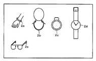
상술한 것처럼, 이 실시 형태의 멀티 터치·멀티 유저 검출 장치(1)에 대해서 지시 조작을 행하는 각 유저는 멀티 유저의 검출을 가능하게 하기 때문에, 유저마다 다른 주파수 신호를 발생시키는 신호 발생기(2)를 구비한다. 이 신호 발생기(2)는 소정 전압 레벨 이상의 신호를 발생시킬 수 있으면 좋으므로, 다양한 형태로 실현될 수 있다.As described above, since each user who performs the instruction operation with respect to the multi-touch
도 10은 신호 발생기(2)의 실시 양태를 설명하기 위한 도면이다. 신호 발생기(2)는 유저가 몸에 걸침으로써, 유저의 신체 및 지시체를 통해서, 멀티 터치·멀티 유저 검출 장치(1)에 대해서 유저마다 다른 주파수 신호를 공급하는 것이다. 이 때문에, 신호 발생기(2)는 도 10에 도시된 바와 같이, 유저의 팔에 착용되는 팔찌(2a)의 구성으로 하거나, 유저의 목에 착용되는 목걸이(2b)나 펜던트의 구성으로 하거나, 유저의 손가락에 착용되는 반지(2c)의 구성으로 할 수 있다. 또, 신호 발생기(2)는 도 10에 도시된 바와 같이, 유저의 팔에 작용되는 손목시계(2d)의 구성으로 하거나, 유저의 안면부에 착용되는 안경(2e)의 구성으로 할 수도 있다.Fig. 10 is a diagram for explaining an embodiment of the signal generator 2. Fig. The signal generator 2 feeds a frequency signal different for each user to the multi-touch multi-user detecting
이 외, 도시하지 않았지만, 신호 발생기(2)는 명함 보관함이나 수첩 사이즈의 상형(箱型)의 것으로 하여, 이것을 유저의 의복 주머니 등에 넣어 이용하는 구성으로 하는 등도 가능하다. 또, 신호 발생기(2) 자체는 멀티 터치·멀티 유저 검출 장치(1)가 마련되는 정보 처리 장치측에 마련되어, 이 정보 처리 장치측에 마련된 신호 발생기(2)로부터의 신호를 케이블 등을 통해서 유저에게 공급하고, 당해 유저의 신체 및 지시체를 통해서 멀티 터치·멀티 유저 검출 장치(1)에 공급하는 구성으로 하는 것도 가능하다.In addition, although not shown, the signal generator 2 may be configured as a business card storage box or a pocket-sized box type, and may be used by putting it in a user's clothes pocket or the like. The signal generator 2 itself is provided on the information processing apparatus side provided with the multi-touch
[변형예등][Modifications]
[기본적인 구성] [Basic configuration]
상술한 실시 형태에 있어서는, 도 2, 도 3을 이용하여 설명한 것처럼, 복수의 제1 도체에 소정 신호를 공급하고, 복수의 제2 도체로부터의 신호를 수신하여, 복수의 지시 위치와 지시체 식별 정보를 검출하고, 어느 위치가 어느 지시체에 의해 지시되었는지를 검출했다. 이 경우, 증폭 회로(31)나 A/D 변환 회로(32)를 가지는 수신부(300A)에 있어서, 지시체 식별 정보(유저 ID)를 검출할 수 있도록 했다. 또, 복수의 제1 도체에는 주파수가 다른 신호를 공급함과 아울러, 이것들과는 다른 주파수 신호를 각 지시체로부터 공급하도록 하여, 멀티 터치와 멀티 유저의 검출을 가능하게 했다.In the above-described embodiment, as described with reference to Figs. 2 and 3, a predetermined signal is supplied to a plurality of first conductors, a signal from the plurality of second conductors is received, And it was detected which position indicated by which indicator. In this case, the receiving
[부호 다중 방식, 위상 시프트 방식의 이용] [Use of code multiplexing method, phase shift method]
그러나 이것에 한정하는 것은 아니다. 복수의 제1 도체에 공급하는 신호나 각 지시체로부터 제2 도체에 공급되는 신호는 주파수가 다른 신호로 바뀌고, 코드 패턴이 다른 복수의 코드를 사용하도록 할 수도 있다. 여기서, 코드 패턴이 다른 복수의 코드의 예로서는, 다른 PN(Pseudorandom Noise)부호 등의 확산 부호를 이용하도록 하거나, 동일한 코드 패턴으로 서로 위상이 다른 복수의 코드를 이용하도록 할 수도 있다. 이와 같이 코드 패턴이 다른 복수의 코드를 이용하도록 하는 경우, 멀티 터치나 멀티 유저의 검출은 사용하는 코드에 대응한 코드와의 상관값을 검출하는 것에 의해 행하는 것이 가능하다.However, it is not limited to this. A signal to be supplied to the plurality of first conductors or a signal supplied to the second conductor from each indicator may be changed to a signal having a different frequency and a plurality of codes having different code patterns may be used. Here, as an example of a plurality of codes having different code patterns, a spread code such as another PN (Pseudorandom Noise) code may be used, or a plurality of codes having the same code pattern and different phases from each other may be used. When a plurality of codes having different code patterns are used as described above, the multi-touch or multi-user detection can be performed by detecting a correlation value with a code corresponding to the code to be used.
보다 구체적으로는, 상술한 것처럼, 부호 다중 방식을 이용한 크로스 포인트형 정전 결합 방식의 지시체 검출 장치에 대한 출원인 특원 2009-288273의 출원 서류나, 위상 시프트 방식을 이용한 크로스 포인트형 정전 결합 방식의 지시체 검출 장치에 대한 출원의 공개 공보인 특허 문헌 2(특개 2011-3036호 공보)에 상세하게 개시되어 있다. 그리고 멀티 유저의 검출에 대해서도, 멀티 터치의 검출과 같게 하여 행할 수 있다.More specifically, as described above, the application documents of the applicant's patent application 2009-288273 to the cross point type electrostatic coupling type indicator device using the code multiplexing method and the pointing device detection of the cross point type electrostatic coupling method using the phase shift method (Patent Document 2) (Japanese Patent Application Laid-Open No. 2011-3036), which is an open publication of the application for the apparatus. The multi-user detection can be performed in the same manner as the multi-touch detection.
또, 상술한 것처럼, 복수의 제1 도체 각각 마다, 주파수가 다른 신호나 코드 패턴이 다른 신호를 공급하도록 해도 좋지만, 이것에 한정하는 것은 아니다. 복수의 제1 도체와 복수의 제2 도체 각각에 대해서, 소정 수의 도체마다 그룹화한다. 그리고 복수의 제1 도체에 대해서는, 그룹마다 다른 신호를 이용하도록 하여, 당해 신호를 공급하는 제1 도체를 차례로 절환하도록 한다. 또, 복수의 제2 도체에 대해서도, 그룹마다 수신한 신호를 출력하는 도체를 절환하여 수신한 신호의 검출을 도체마다 차례로 행하도록 한다.Also, as described above, signals having different frequencies or different code patterns may be supplied to each of the plurality of first conductors, but the present invention is not limited thereto. The plurality of first conductors and the plurality of second conductors are grouped for each predetermined number of conductors. For the plurality of first conductors, different signals are used for each group, and the first conductors for supplying the signals are sequentially switched. Also, with respect to a plurality of second conductors, conductors for outputting signals received for each group are switched, and the received signals are sequentially detected for each conductor.
이와 같이, 제1, 제2 도체를 그룹화하고, 그룹 단위로 처리를 행하도록 함으로써, 제1 도체에 공급해야 할 신호의 종류를 줄일 수 있고, 또 회로 구성의 단순화를 도모할 수 있게 된다. 또한, 그룹화의 구체적인 수법에 대해서도, 상술한 특허 문헌 1, 2, 및, 특원 2009-288273의 출원 서류에 개시되어 있는 방식을 이용하도록 할 수 있다.As described above, by grouping the first and second conductors and performing the processing in units of groups, it is possible to reduce the kinds of signals to be supplied to the first conductor, and simplify the circuit configuration. Also, with respect to the specific method of grouping, the methods disclosed in the above-mentioned
[센서 도체의 일면측에 표시 장치를 배치, EMR 방식의 사용][Placement of display device on one side of sensor conductor, use of EMR method]
또, 도 7을 이용하여 설명한 것처럼, 디스플레이 장치(표시 장치: 3A)를 멀티 터치·멀티 유저 검출 장치(1)의 센서 도체의 일면측, 구체적으로는 지시체가 위치를 지시하는 측과 동일한 측에 마련하도록 할 수 있다. 이 경우, 디스플레이 장치(3A)의 표시면측과는 반대로 위치하는 이면(裏面)측에 멀티 터치·멀티 유저 검출 장치(1)를 마련할 수 있으므로, 멀티 터치·멀티 유저 검출 장치(1)로서는 EMR(Electro Magnetic Resonator) 방식의 것을 이용할 수 있다.7, the display device (display device 3A) is disposed on one side of the sensor conductor of the multi-touch
여기서, EMR 방식의 검출 장치는 잘 알려져 있는 것처럼, 지시체로서의 전자 펜에 의해서 지시되는 위치를 검출하는 센서 보드와 컨트롤 보드에 의해 구성되는 것이다. 센서 보드는 종횡 방향으로 다수의 루프 코일이 배치된 얇은 필름 형상을 하고 있다. 센서 보드의 배면(背面)에는 메인 보드 등의 다른 기판이나 회로로부터의 노이즈를 차폐(遮蔽)하는 쉴드판이 마련되어 있다. 또, 컨트롤 보드는 센서 보드에 배치된 루프 코일을 차례로 절환하여 교류 전류를 흘릴 수 있는 것이다. 이것에 의해, 루프 코일로부터 자계가 발생하고, 이 자계 가운데를 지시체로서의 전자 펜이 통과하면 당해 전자 펜의 공진 회로에 의해 당해 전자 펜에 에너지를 축적할 수 있다.Here, as is well known, the detection device of the EMR system is constituted by a sensor board and a control board which detect the position indicated by the electronic pen as a pointing device. The sensor board has a thin film shape in which a plurality of loop coils are arranged in the longitudinal and transverse directions. The back surface of the sensor board is provided with a shield plate for shielding noise from other boards or circuits such as a main board. In addition, the control board is capable of alternately switching the loop coils disposed on the sensor board to flow alternating current. As a result, when a magnetic field is generated from the loop coil and the electronic pen as a pointing object passes through the magnetic field, energy can be accumulated in the electronic pen by the resonance circuit of the electronic pen.
다음으로, 컨트롤 보드는 루프 코일로의 전류 공급을 정지하고, 루프 코일을 수신 회로에 접속한다. 그러면, 전자 펜의 공진 회로의 자유 진동에 의해, 전자 펜에 축적된 에너지가 펜 끝의 코일로부터 센서 보드로 되돌려 보내진다. 전자 펜으로부터의 에너지는 센서 보드에 의해 수신되고 수신 회로를 경유해서 A/D 변환되어 정보로서 검출된다. 컨트롤 보드는 센서 보드 위의 루프 코일을 차례로 절환하여 검출 신호를 계산함으로써, 센서 보드 위의 전자 펜의 좌표값을 높은 정밀도로산출하여 특정할 수 있다.Next, the control board stops supplying the current to the loop coil, and connects the loop coil to the receiving circuit. Then, by the free vibration of the resonance circuit of the electronic pen, the energy stored in the electronic pen is returned from the coil of the pen tip to the sensor board. The energy from the electronic pen is received by the sensor board and A / D converted via the receiving circuit to be detected as information. The control board calculates the detection signal by sequentially switching the loop coil on the sensor board, so that the coordinate value of the electronic pen on the sensor board can be calculated and specified with high precision.
그리고 이 EMR 방식을 이용하여 멀티 터치, 멀티 유저 검출 장치를 구성한 경우, 전자 펜으로부터 센서 보드에 되돌려 보내는 신호를, 전자 펜마다 다르게 함으로써, 지시 위치뿐만 아니라 전자 펜마다의 식별도 행할 수 있다. 즉, EMR 방식의 검출 방식을 이용하는 것에 의해서도, 본 발명의 멀티 터치, 멀티 유저 검출 장치를 실현할 수 있다. 또한, EMR 방식의 좌표 입력 장치에 관한 기본적인 기술은, 예를 들면 특개소 64-53223호 공보 등에 개시되어 있다.When the multi-touch or multi-user detection device is configured by using this EMR method, the signal sent back from the electronic pen to the sensor board is different for each electronic pen, so that not only the pointed position but also each electronic pen can be identified. That is, the multi-touch and multi-user detection device of the present invention can be realized by using the EMR detection method. A basic technique related to the coordinate input device of the EMR system is disclosed in, for example, Japanese Patent Application Laid-Open No. 64-53223.
[검출 장치와 표시 장치의 적층] [Lamination of Detection Apparatus and Display Apparatus]
또, 도 1을 이용하여 설명한 것처럼, 멀티 터치·멀티 유저 검출 장치(1)의 센서 도체의 일면측에 지시체가 대향하고, 타면측에 표시 장치를 배치할 수도 있다. 간단하게는, 멀티 터치·멀티 유저 검출 장치(1)의 하측에 디스플레이 장치(표시 장치: 3)를 마련한 중첩 구조로 할 수 있다.1, the indicator may face the one surface of the sensor conductor of the multi-touch
[정전 방식, 저항막 방식의 이용] [Use of electrostatic method, resistive method]
이 경우에, 멀티 터치·멀티 유저 검출 장치(1)로서는, 상술한 크로스 포인트형 정전 결합 방식 등의 이른바 정전 방식을 이용하는 것 외에, 투과성을 가지는 검출 장치로서 저항막 방식을 이용하여 멀티 터치·멀티 유저 검출 장치를 실현할 수도 있다.In this case, as the multi-touch multi-user detecting
여기서, 저항막 방식의 터치 센서는, 간단하게는 베이스가 되는 유리면의 표면에 매우 작은 스페이스(수㎛(마이크로 미터))를 사이에 두고, 그 표면에 유연한 필름(200㎛정도)을 부착하여 구성한다. 당해 유리와 당해 필름이 서로 마주 보는 면에는, 예를 들면 ITO(Indium Tin Oxide)의 투명한 전극 격자(복수의 제1, 제2 도체)가 마련된다.Here, the resistance film type touch sensor is constituted by attaching a flexible film (about 200 占 퐉) to the surface of a glass surface to be a base, with a very small space (several micrometers) do. A transparent electrode grid (a plurality of first and second conductors) of, for example, ITO (Indium Tin Oxide) is provided on the surface where the glass and the film face each other.
이와 같이 구성되는 저항막 방식의 터치 센서에 있어서는, 지시체에 의해 터치되고 있지 않은 상태에서는, 미소한 스페이스에 의해, 대향하는 전극은 접촉하고 있지 않기 때문에 전류는 흐르지 않는다. 그러나 필름면을 손가락 등의 지시체에 의해 터치하면 압력에 의해 필름이 휘어서, 대향하는 전극이 접촉하여 전류가 흐른다. 그리고 유리면 및 필름면 각각의 투명 전극의 저항에 의한 분압비를 측정함으로써 지시체의 접촉 위치를 검출할 수 있게 된다.In the resistive film type touch sensor constructed as described above, no current flows because the opposing electrodes are not in contact with each other due to a small space in a state where the touching is not performed by the indicating body. However, when the film surface is touched by a pointing device such as a finger or the like, the film is bent by the pressure, and the opposing electrodes come into contact with each other and a current flows. Then, the contact position of the pointing device can be detected by measuring the partial pressure ratio due to the resistance of each transparent electrode on the glass surface and the film surface.
이 경우에, 지시체로부터 지시체마다 다른 신호(주파수나 코드 패턴이 다른 신호)를 공급하여, 이것을 격자 모양으로 배치되는 전극에 대응하여 검출하면, 지시 위치마다 지시체의 식별도 행할 수 있다. 즉, 저항막 방식의 검출 방식을 이용하는 것에 의해서도, 본 발명의 멀티 터치, 멀티 유저 검출 장치를 실현할 수 있다.In this case, if a different signal (a signal having a different frequency or a different code pattern) is supplied from the indicating body to each of the indicating bodies and the detected signal is detected corresponding to the electrodes arranged in a lattice pattern, the indicating body can be identified for each indicating position. That is, the multi-touch and multi-user detection device of the present invention can be realized by using the resistance film type detection method.
[제2 지시체 식별 정보 검출 회로의 이용][Use of Second Indicator Identification Information Detection Circuit]
또, 도 8, 도 9를 이용하여 설명한 것처럼, Y축 방향 유저 ID 검출부(500)를 마련하고, 당해 Y축 방향 유저 ID 검출부(500)로의 검출 처리를 행하는 기간에 있어서는, 제1 도체에는 신호를 공급하지 않게 하는 것을 설명했다. 이 경우, 제1 도체에 신호를 공급하는 기간과, 제1 도체로의 신호 공급을 정지하고, Y축 방향 유저 ID 검출부(500)로 검출 처리를 실행하는 기간은, 반드시 동일한 시간 기간으로 할 필요는 없다. Y축 방향 유저 ID 검출부(500)의 동작 기간보다도, 제1 도체에 신호를 공급하여 수신부(300A)나 수신부(300) 및 X축 방향 유저 ID 검출부(400)를 동작시키는 기간을 길게 하거나, 또 그 반대로 할 수도 있다.As described with reference to Figs. 8 and 9, in the period in which the Y-axis direction user
제1 도체에 신호를 공급하는 기간은 수신부(300A), 또는 수신부(300A) 및 X축 방향 유저 ID 검출부(400)로의 처리가 적정하게 실행 가능한 기간으로 하면 좋다. 또, 제1 도체에 신호를 공급하지 않는 기간은, Y축 방향 유저 ID 검출부(500)로의 처리가 적정하게 실행 가능한 기간으로 하면 좋다.The period during which the signal is supplied to the first conductor may be a period in which the processing by the receiving
[제1, 제2 지시체 식별 정보 검출 회로의 이용] [Use of First and Second Indicator Identification Information Detection Circuit]
또, 상술한 것처럼, 수신부(300A)와 Y축 방향 유저 ID 검출부(500)를 상시 함께 이용하도록 하거나, 수신부(300) 및 X축 방향 유저 ID 검출부(400)와 Y축 방향 유저 ID 검출부(500)를 상시 함께 이용하도록 하는 것도 가능하다. 또, 수신부(300A) 또는 X축 방향 유저 ID 검출부(400)에 있어서, 복수의 유저가 지시체를 이용한 지시 조작을 행하고 있는 것을 검출했을 경우에, Y축 방향 유저 ID 검출부(500)를 기능시키도록 할 수도 있다.As described above, the receiving
[지시 위치의 형상, 색에 의한 식별] [Shape of indication position, identification by color]
또, 도 6, 도 7을 이용하여 설명한 것처럼, 지시 위치를 지시체마다 형상, 색에 의해서 서로 식별할 수 있도록 할 수 있다. 이 경우, 형상은 사각형이나 원형 외, 성(星)형, 삼각형 이상의 다각형 등을 이용할 수 있고, 색도 디스플레이 장치(3,3A)가 표현 가능한 다양한 색을 이용하는 것이 가능하다.As described with reference to Figs. 6 and 7, it is possible to identify the pointing position from each other by shape and color for each pointing body. In this case, the shape can be a rectangular or non-circular shape, a star shape, a polygonal shape larger than a triangle, or the like, and it is possible to use various colors capable of being expressed by the chromaticity display device 3, 3A.
[영역의 테두리 선, 배경색에 의한 식별][Identification by area border line, background color]
또, 지시체에 의해 조작이 행해진 영역을 테두리 선이나 배경색을 바꾸는 것으로서 나타내도록 할 수도 있다. 이 경우, 테두리 선의 선종이나 배경색도, 디스플레이(3,3A)에 있어서 표시 가능한 여러 가지의 것을 이용할 수 있다.In addition, the area where the operation is performed by the indicating body may be represented by changing the border line or the background color. In this case, various types of display lines 3, 3A can be used for the line type of the border line and the background color.
[영역의 이동, 정보의 카피, 이동 등] [Movement of area, copy of information, movement, etc.]
또, 유저에 의해서 설정되는 표시 영역 자체를 디스플레이 장치(3, 3A)의 표시 화면에 있어서 적당한 위치로 이동시키도록 하거나, 표시 영역에 표시되고 있는 정보의 다른 표시 영역으로의 카피, 이동 외, 추가나 삭제 등, 여러 가지의 편집 작업을 행할 수 있도록 하는 것도 가능하다. 당해 처리는 멀티 터치·멀티 유저 검출 장치(1)로의 유저의 조작 입력에 기초하여, 표시 제어 장치(퍼스널 컴퓨터: 4,4A)가 실현한다.It is also possible to move the display area itself set by the user to a suitable position on the display screen of the display device 3 or 3A or to add information other than copying, It is also possible to perform various editing operations such as deletion. This process is realized by the display control device (personal computer: 4, 4A) based on the user's operation input to the multi-touch
[멀티 유저인지 단일 유저인지의 검출 출력] [Multi-user or single-user detection output]
또, 상술한 것처럼, 수신부(300)나 X축 방향 유저 ID 검출부(400)에 있어서는, 각 지시체를 이용하고 있는 유저의 검출이 가능하다. 이 때문에, 수신부(300)나 X축 방향 유저 ID 검출부(400)는, 지시체를 이용하여 조작 입력을 행하고 있는 대상이 단독 유저인지 복수 유저인지의 구별을 출력하도록 하거나, 지시체를 이용하여 조작 입력을 행하고 있는 유저의 수를 출력할 수 있다.As described above, in the receiving
[제1, 제2 도체의 다른 구성예] [Other Configuration Examples of the First and Second Conductors]
또한, 직선 모양으로 형성된 송신 도체(11Y)와 수신 도체(12X)를 직교하도록 배치한 경우를 예시하여 설명했지만, 송신 도체(11Y) 및 수신 도체(12X)의 형상은 실시 양태에 따라 적당하게 설정된다. 또, 송신 도체(11Y)와 수신 도체(12X)는 직교 이외의 각도, 예를 들면, 송신 도체(11Y)와 수신 도체(12X)가 비스듬하게 교차하는 구성으로 하여도 좋다.The
또, 전기 특성상, 수신 도체(12X)의 폭은 송신 도체(11Y)의 폭보다 가늘게 형성하면 좋다. 부유 용량이 줄어듦으로써, 수신 도체(12X)에 혼입하는 노이즈를 저감할 수 있기 때문이다.In addition, due to the electrical characteristics, the width of the
또, 송신 도체(11Y) 및 수신 도체(12X)의 적어도 한쪽은 곡선 모양 또는 동심원 모양으로 형성한 도체로 구성해도 좋다. 예를 들면 복수의 송신 도체(11Y)를 각각 지름이 다른 원형 모양으로 형성하고, 이것을 동심원 모양으로 배치함과 아울러, 복수의 수신 도체(12X)를 상기 동심원의 중심으로부터 방사 모양으로 연장한 직선 형상의 복수의 도체에 의해 형성하고, 그 복수의 직선 형상의 도체를 주(周)방향으로 등각(等角) 간격으로 배치하도록 해도 좋다.At least one of the
즉, 송신 도체(11Y) 및 수신 도체(12X)의 구성은, 예를 들면, 특개 2011-3035 공보의 도 15 ~ 도 20에 개시되어 있는 것과 같은 여러 가지의 것으로 하는 것이 가능하다.That is, the structures of the transmitting
[그 외] [etc]
또한, 상술한 실시 형태에 있어서는, 유저마다 신호 발생기(2)를 마련하는 것으로서 설명했다. 이 경우, 1명의 유저가 자신의 복수의 손가락을 지시체로서 이용하여 동시에 센서부(100)에 접촉한 경우더라도, 동일한 유저가 다른 손가락에 의해서 지시된 지시 위치는 동일한 유저에 의해서 지시된 지시 위치로서 검출할 수 있다.In the above-described embodiment, the signal generator 2 is provided for each user. In this case, even when one user contacts his / her sensor unit 100 simultaneously using his / her plurality of fingers as a pointing member, the pointed position pointed by the other finger of the same user is indicated as the pointed position pointed by the same user Can be detected.
또, 예를 들면, 터치 펜 등의 지시체마다 발진 회로를 마련하도록 한 경우에는, 동일한 유저가 다른 지시체를 이용하여 지시 입력을 행하면, 각각의 지시체마다 지시 위치를 구별해서 검출할 수 있다. 즉, 1명의 유저가 다른 지시체(터치 펜)를 이용하여 지시 입력을 실시한 경우에는, 유저마다가 아니고 지시체마다 지시 위치를 특정할 수 있다.Further, for example, when an oscillation circuit is provided for each indicating body such as a touch pen, when the same user performs instruction input using another indicating body, the indication position can be detected for each indicating body separately. That is, when one user performs an instruction input using another indicating body (touch pen), the indication position can be specified for each indicating body, not for each user.
1: 멀티 터치·멀티 유저 검출 장치100: 센서부
100S: 지시 입력면11: 송신 도체군
11Y1~ 11Y64: 송신 도체12: 수신 도체군
12X1 ~ 12X64: 수신 도체200: 송신부
21: 송신 신호 공급 회로22: 클럭 생성 회로
300: 수신부31: 증폭 회로
32: A/D 변환 회로33A: 유저 및 위치 식별 회로
331: 유저 ID 식별 필터332: 지시 위치 식별 필터
34A: 위치 검출 회로40: 제어 회로
2, 2A, 2B: 신호 발생기
3, 3A: 디스플레이 장치(표시 장치)
4, 4A: 표시 제어 장치300: 수신부
400: X축 방향 유저 ID 검출부500: Y축 방향 유저 ID 검출부1: Multi-touch multi-user detecting device 100: Sensor part
100S: Instruction input surface 11: Transmission conductor group
11Y1 ~ 11Y64 : transmitting conductor 12: receiving conductor group
12X1 to 12X64 : receiving conductor 200:
21: Transmission signal supply circuit 22: Clock generation circuit
300: receiving section 31: amplifying circuit
32: A /
331: User ID identification filter 332: Indicated position identification filter
34A: position detection circuit 40: control circuit
2, 2A, 2B: Signal generator
3, 3A: Display device (display device)
4, 4A: display control device 300:
400: X axis direction user ID detection unit 500: Y axis direction user ID detection unit
Claims (17)
Translated fromKorean상기 제1 방향으로 배치된 복수의 제1 도체에 소정 신호를 공급하기 위한 신호 송신 회로와,
상기 제2 방향으로 배치된 복수의 제2 도체로부터의 신호를 수신하는 신호 수신 회로와,
상기 신호 수신 회로로부터 출력된 신호에 기초하여, 상기 센서 도체에 대해서 복수의 지시체가 지시하는 위치를 검출하는 지시 위치 검출 회로와,
상기 지시체가 지시하는 위치에 대응하여 상기 센서 도체로부터 수신된 신호로부터, 상기 신호 송신 회로에 의해서 상기 제1 방향으로 배치된 복수의 제1 도체에 공급되는 신호와 식별 가능한 지시체 식별 정보를 검출하는 제1 지시체 식별 정보 검출 회로와,
상기 지시 위치 검출 회로로부터 출력된 위치 정보와 상기 제1 지시체 식별 정보 검출 회로로부터 출력된 지시체 식별 정보에 기초하여, 복수의 지시체에 의해서 지시된 위치가 어느 지시체에 의한 지시인지의 대응 관계를 특정하기 위한 대응 관계 특정 회로를 구비함으로써,
상기 센서 도체에 대해서 상기 복수의 지시체가 지시하는 각각의 위치와 상기 복수의 지시체의 대응 관계를 특정할 수 있도록 한 것을 특징으로 하는 멀티 터치·멀티 유저 검출 장치.A sensor conductor comprising a plurality of first conductors arranged in a first direction and a plurality of second conductors arranged in a second direction crossing the first direction,
A signal transmission circuit for supplying a predetermined signal to a plurality of first conductors arranged in the first direction,
A signal receiving circuit for receiving signals from a plurality of second conductors arranged in the second direction,
An indication position detecting circuit for detecting a position indicated by a plurality of indicating bodies with respect to the sensor conductor based on the signal outputted from the signal receiving circuit;
A signal detecting circuit for detecting from a signal received from the sensor conductor corresponding to a position pointed by the indicating body a signal to be supplied to the plurality of first conductors arranged in the first direction by the signal transmitting circuit, 1 indicating body identification information detecting circuit,
The correspondence relationship between the indication indicated by the plurality of indication bodies and the indication by which indication body is specified is determined based on the position information outputted from the indication position detection circuit and the indicator body identification information outputted from the first indicator body identification information detection circuit By providing a correspondence relationship specifying circuit for the above-
Wherein the sensor conductor is capable of specifying respective positions indicated by the plurality of indicating bodies and a corresponding relationship between the plurality of indicating bodies with respect to the sensor conductor.
Applications Claiming Priority (2)
| Application Number | Priority Date | Filing Date | Title |
|---|---|---|---|
| JPJP-P-2011-100348 | 2011-04-28 | ||
| JP2011100348AJP5743198B2 (en) | 2011-04-28 | 2011-04-28 | Multi-touch multi-user detection device |
Publications (2)
| Publication Number | Publication Date |
|---|---|
| KR20120122900A KR20120122900A (en) | 2012-11-07 |
| KR101898291B1true KR101898291B1 (en) | 2018-09-12 |
Family
ID=46027628
Family Applications (1)
| Application Number | Title | Priority Date | Filing Date |
|---|---|---|---|
| KR1020120040288AActiveKR101898291B1 (en) | 2011-04-28 | 2012-04-18 | Multi-touch and multi-user detecting device |
Country Status (7)
| Country | Link |
|---|---|
| US (2) | US9081437B2 (en) |
| EP (1) | EP2518603B1 (en) |
| JP (1) | JP5743198B2 (en) |
| KR (1) | KR101898291B1 (en) |
| CN (2) | CN102760007B (en) |
| IL (1) | IL218563A (en) |
| TW (1) | TWI563421B (en) |
Cited By (1)
| Publication number | Priority date | Publication date | Assignee | Title |
|---|---|---|---|---|
| US12373056B2 (en) | 2023-08-29 | 2025-07-29 | Samsung Display Co., Ltd. | Multi-user touch detection circuit and display device including the same |
Families Citing this family (120)
| Publication number | Priority date | Publication date | Assignee | Title |
|---|---|---|---|---|
| JP5929572B2 (en)* | 2012-07-09 | 2016-06-08 | コニカミノルタ株式会社 | Operation display device and program |
| US20140043277A1 (en)* | 2012-08-09 | 2014-02-13 | Nokia Corporation | Apparatus and associated methods |
| KR20140021899A (en)* | 2012-08-13 | 2014-02-21 | 삼성전자주식회사 | Method for moving contents and an electronic device thereof |
| TWI485610B (en)* | 2012-12-28 | 2015-05-21 | Egalax Empia Technology Inc | Method and device for detecting touch or proximity |
| CN103838414B (en)* | 2012-11-27 | 2018-10-12 | 联想(北京)有限公司 | A kind of recognition methods and a kind of electronic equipment |
| CN103870041B (en)* | 2012-12-14 | 2017-09-22 | 联想(北京)有限公司 | terminal device and its user identification method |
| JP2014160415A (en)* | 2013-02-20 | 2014-09-04 | Fuji Xerox Co Ltd | Browsing device, browsing system, information processing apparatus, and program |
| JP2014178790A (en)* | 2013-03-14 | 2014-09-25 | Ricoh Co Ltd | Projection system, projection device, projection program, and projection method |
| EP2972701A4 (en)* | 2013-03-15 | 2017-01-25 | Tactual Labs Co. | Fast multi-touch sensor with user identification techniques |
| JP6443942B2 (en)* | 2013-03-15 | 2018-12-26 | タクチュアル ラブズ シーオー. | High-speed multi-touch sensor with user identification technology |
| US9507464B2 (en) | 2013-03-15 | 2016-11-29 | Elo Touch Solutions, Inc. | Acoustic touch apparatus and methods using touch sensitive lamb waves |
| SG11201506843PA (en)* | 2013-03-15 | 2015-09-29 | Tactual Labs Co | Fast multi-touch noise reduction |
| US9830015B2 (en)* | 2013-03-15 | 2017-11-28 | Tactual Labs Co. | Orthogonal frequency scan scheme in touch system |
| KR102138512B1 (en)* | 2013-03-26 | 2020-07-28 | 엘지전자 주식회사 | Display Device And Controlling Method Thereof |
| CN103218075B (en)* | 2013-03-26 | 2016-12-28 | 深圳市金立通信设备有限公司 | The touch-control monitoring method of a kind of Touch Screen and terminal |
| US9182867B2 (en)* | 2013-04-25 | 2015-11-10 | Anapass Inc. | Apparatus and method for detecting adjacent object and method of driving electronic device |
| KR102131257B1 (en) | 2013-07-02 | 2020-07-07 | 삼성전자주식회사 | Electronic device and method for controlling multi- window in the electronic device |
| JP5882270B2 (en)* | 2013-08-29 | 2016-03-09 | 東芝テック株式会社 | Information processing apparatus and program |
| US11409379B2 (en) | 2013-11-08 | 2022-08-09 | Egalax_Empia Technology Inc. | Stylus and operating method thereof for transmitting electrical signals carrying pressure information |
| US10503318B2 (en)* | 2015-06-16 | 2019-12-10 | Egalax_Empia Technology Inc. | Touch sensitive processing apparatus and system for despreading and method thereof |
| US10895921B2 (en) | 2013-11-08 | 2021-01-19 | Egalax_Empia Technology Inc. | Touch sensitive processing apparatus, system and operating method thereof for receiving electrical signals carrying pressure information |
| US10890987B2 (en) | 2013-11-08 | 2021-01-12 | Egalax_Empia Technology Inc. | Stylus and operating method thereof for transmitting electrical signals carrying pressure information |
| US11392221B2 (en) | 2013-11-08 | 2022-07-19 | Egalax_Empia Technology Inc. | Touch sensitive processing apparatus, system and operating method thereof for receiving electrical signals carrying pressure information |
| KR101460104B1 (en)* | 2014-01-24 | 2014-11-20 | 주식회사 아나패스 | Method for Driving an Electronic Device having A Touch Panel |
| CN106062618B (en)* | 2014-02-28 | 2019-04-16 | 凸版印刷株式会社 | Liquid crystal display device |
| JP6269227B2 (en) | 2014-03-25 | 2018-01-31 | セイコーエプソン株式会社 | Display device, projector, and display control method |
| TWI641986B (en)* | 2014-06-01 | 2018-11-21 | 美商英特爾公司 | Method, electronic device and computer readable medium for determining the number of users and their respective positions relative to a device |
| US10867149B2 (en) | 2014-06-12 | 2020-12-15 | Verizon Media Inc. | User identification through an external device on a per touch basis on touch sensitive devices |
| US9396378B2 (en)* | 2014-06-12 | 2016-07-19 | Yahoo! | User identification on a per touch basis on touch sensitive devices |
| KR101538791B1 (en)* | 2014-06-18 | 2015-07-24 | 한국산업은행 | Interactive white board |
| EP3907590A3 (en)* | 2014-06-24 | 2022-02-09 | Sony Group Corporation | Information processing device, information processing method, and computer program |
| FR3027126B1 (en)* | 2014-10-10 | 2017-12-01 | Thales Sa | IDENTIFICATION AND DATA EXCHANGE SYSTEM COMPRISING A PORTABLE CAPACITIVE DEVICE AND A CAPACITIVE TOUCH SCREEN |
| US9720539B2 (en)* | 2014-11-25 | 2017-08-01 | Robert Dennis Kennedy | Tablet computer screen and mobile phone screen to digital I/O converter |
| JP6350261B2 (en)* | 2014-12-17 | 2018-07-04 | コニカミノルタ株式会社 | Object operation system, object operation control program, and object operation control method |
| CN104598071B (en)* | 2014-12-29 | 2018-04-27 | 联想(北京)有限公司 | A kind of information processing method and electronic equipment |
| EP3254178A4 (en)* | 2015-02-02 | 2018-08-15 | Tangiamo Touch Technology AB | Multi-touch user interface for an electronic device |
| EP3267293B1 (en)* | 2015-03-02 | 2019-09-18 | Wacom Co., Ltd. | Active capacitive stylus, sensor controller, system comprising these, and method executed by these |
| US11269455B1 (en) | 2020-10-23 | 2022-03-08 | Sigmasense, Llc. | Enhanced mutual capacitance touch screen display with noise compensation and methods for use therewith |
| US10664098B2 (en) | 2015-06-22 | 2020-05-26 | Sigmasense, Llc. | Channel driver circuit |
| CN107077264B (en) | 2015-06-22 | 2020-06-16 | 西格玛森斯科技有限公司 | Multi-touch sensor and electrostatic pen digitizer system utilizing simultaneous functionality to achieve improved performance |
| US11397492B2 (en) | 2015-06-22 | 2022-07-26 | Sigmasense, Llc. | Enhanced mutual capacitance touch screen display with shape detection and methods for use therewith |
| US11907484B2 (en) | 2015-06-22 | 2024-02-20 | Sigmasense, Llc. | Function and orientation identification for input/output (I/O) operative touch sensor device (TSD) |
| CN106716314B (en) | 2015-07-06 | 2020-02-28 | 3轴数据有限责任公司 | Pen system with internal pressure inclined rotation |
| JP2017102894A (en)* | 2015-10-30 | 2017-06-08 | パナソニックIpマネジメント株式会社 | Detection device |
| JP6426639B2 (en)* | 2016-02-25 | 2018-11-21 | ファナック株式会社 | Data transmission system, touch panel device, and data transmission method |
| KR102523154B1 (en) | 2016-04-22 | 2023-04-21 | 삼성전자주식회사 | Display apparatus, input device and control method thereof |
| US20180049671A1 (en) | 2016-08-18 | 2018-02-22 | Timothy W. Markison | Wireless in-shoe physical activity monitoring dongle |
| US12207703B2 (en) | 2016-08-18 | 2025-01-28 | Sigmasense, Llc. | Shoe to shoe communication within a foot force detection system |
| US12225979B2 (en) | 2016-08-18 | 2025-02-18 | Sigmasense, Llc. | Variable sampling rate within a foot force detection system |
| US12181352B2 (en) | 2021-06-03 | 2024-12-31 | Sigmasense, Llc. | Insole XYZ force detection system |
| US12194344B2 (en) | 2016-08-18 | 2025-01-14 | Sigmasense, Llc. | Plurality of layers of pressure sensors within a foot force detection system |
| US12226674B2 (en) | 2016-08-18 | 2025-02-18 | Sigmasense, Llc. | Power harvesting in a foot force detection system |
| US12121773B2 (en) | 2016-08-18 | 2024-10-22 | Sigmasense, Llc. | Personal athlete monitoring system |
| US10871896B2 (en)* | 2016-12-07 | 2020-12-22 | Bby Solutions, Inc. | Touchscreen with three-handed gestures system and method |
| KR102318808B1 (en)* | 2017-05-26 | 2021-10-28 | 삼성전자주식회사 | Method for using various type of electronic pen and electronic device thereof |
| CN107479820B (en)* | 2017-08-24 | 2021-01-08 | 深圳恒远智信科技有限公司 | Touch device identification method, terminal device and server |
| US10838530B2 (en) | 2017-09-15 | 2020-11-17 | Sigmasense, Llc. | Touchscreen display with concurrent touch and display operations |
| WO2020023640A1 (en) | 2018-07-24 | 2020-01-30 | Shapirten Laboratories Llc | Power efficient stylus for an electronic device |
| US12007421B2 (en) | 2018-08-27 | 2024-06-11 | Sigmasense, Llc. | Load sensing circuit employing sink and sense configuration |
| US11429226B2 (en) | 2018-08-27 | 2022-08-30 | Sigmasense, Llc. | Analog-digital drive sense circuit |
| US11635396B2 (en) | 2018-08-27 | 2023-04-25 | Sigmasense, Llc. | Sensing device with drive sense circuit and particle sensor and methods for use therewith |
| US10895867B2 (en) | 2018-08-27 | 2021-01-19 | Sigmasense, Llc. | Analog world interfacing for automated systems |
| US11513543B2 (en) | 2018-08-27 | 2022-11-29 | Sigmasense, Llc. | Impedance detect drive sense circuit |
| US11822358B2 (en) | 2018-08-27 | 2023-11-21 | Sigmasense, Llc. | Drive-sense circuit to determine effects of different electrical characteristics on load |
| US11550426B2 (en) | 2018-08-27 | 2023-01-10 | Sigmasense, Llc. | Sensor monitoring system |
| US11644860B2 (en) | 2018-08-27 | 2023-05-09 | Sigmasense, Llc. | Configuring a programmable drive sense unit |
| US11099032B2 (en) | 2018-08-27 | 2021-08-24 | Sigmasense, Llc. | Drive sense circuit with drive-sense line |
| US11914812B2 (en) | 2018-08-27 | 2024-02-27 | Sigmasense, Llc. | Current reference operative drive-sense circuit (DSC) |
| US10845985B2 (en) | 2018-09-14 | 2020-11-24 | Sigmasense, Llc. | Identification in touch systems |
| US11875005B2 (en) | 2018-09-14 | 2024-01-16 | Sigmasense, Llc. | Touch screen display with touchless indications and methods for use therewith |
| US11789555B2 (en) | 2018-09-14 | 2023-10-17 | Sigmasense, Llc. | Touch sense control circuit with noise suppression |
| US10908718B2 (en) | 2018-09-14 | 2021-02-02 | Sigmasense, Llc. | Large touch screen display with integrated electrodes |
| US11899867B2 (en) | 2018-09-14 | 2024-02-13 | Sigmasense, Llc. | Touch screen display with touchless gestures and methods for use therewith |
| US11372510B2 (en) | 2018-11-02 | 2022-06-28 | Sigmasense, Llc. | Multi-conductor touch system |
| US10852857B2 (en) | 2018-11-19 | 2020-12-01 | Sigmasense, Llc. | Frequency diverse e-pen for touch sensor and e-pen systems |
| US10935585B2 (en) | 2018-11-19 | 2021-03-02 | Sigmasense, Llc. | Drive sense circuit with transient suppression |
| US10884967B2 (en) | 2019-01-14 | 2021-01-05 | Sigmasense, Llc. | Low voltage drive circuit with variable frequency characteristics and methods for use therewith |
| US12046214B2 (en) | 2019-03-22 | 2024-07-23 | Sigmasense, Llc. | Display controller with row enable based on drive settle detection |
| JP7152979B2 (en)* | 2019-03-28 | 2022-10-13 | シャープ株式会社 | Information processing equipment |
| US11029782B2 (en) | 2019-05-03 | 2021-06-08 | Sigmasense, Llc. | Light emitting diode (LED) touch display circuit |
| US11131714B2 (en) | 2019-05-31 | 2021-09-28 | Sigmasense, Llc. | Battery monitoring and characterization during charging |
| US11029769B2 (en) | 2019-06-10 | 2021-06-08 | Sigmasense, Llc. | Pen for use with a touch screen |
| US11054920B2 (en) | 2019-06-10 | 2021-07-06 | Sigmasense, Llc. | Pen for use with a touch screen |
| US11126297B2 (en) | 2019-06-10 | 2021-09-21 | Sigmasense, Llc. | Electronic pen with ring-back and other functionalities |
| US11221709B2 (en) | 2019-06-10 | 2022-01-11 | Sigmasense, Llc. | Electronic writing apparatus with ring-back and other functionalities |
| US11216133B2 (en) | 2019-06-10 | 2022-01-04 | Sigmasense, Llc. | Device for use with a touch screen |
| US11555687B2 (en) | 2019-08-08 | 2023-01-17 | Sigmasense, Llc. | Capacitive imaging glove |
| US10908641B1 (en) | 2019-10-09 | 2021-02-02 | Sigmasense, Llc. | Display generated data transmission from user device to touchscreen via user |
| US11216109B2 (en) | 2020-01-07 | 2022-01-04 | Sigmasense, Llc. | Drive-sense control for extended sensor panels |
| US11221704B2 (en) | 2020-02-05 | 2022-01-11 | Sigmasense, Llc. | Screen-to-screen communication via touch sense elements |
| TWI727662B (en)* | 2020-02-14 | 2021-05-11 | 李尚禮 | Resistive touch device and resistive touch-sensing method |
| US11079888B1 (en) | 2020-02-18 | 2021-08-03 | Sigmasense, Llc. | Sensitivity region of interest processing (ROIP) for input/output (I/O) operative touch sensor device (TSD) |
| US11144160B1 (en) | 2020-03-30 | 2021-10-12 | Sigmasense, Llc. | Three-dimensional data reduction method and system |
| CN115552361A (en) | 2020-03-31 | 2022-12-30 | 夏皮滕实验室有限责任公司 | Electrostatic discharge protection for high-efficiency stylus for electronic devices |
| US11182038B2 (en) | 2020-04-08 | 2021-11-23 | Sigmasense, Llc. | Encoded data pattern touchscreen sensing system |
| US11340995B2 (en) | 2020-05-21 | 2022-05-24 | Sigmasense, Llc. | Integrated circuit with programmable input/output module |
| WO2022014441A1 (en)* | 2020-07-16 | 2022-01-20 | ソニーグループ株式会社 | Display device, display method, and program |
| US11304002B2 (en) | 2020-08-12 | 2022-04-12 | Sigmasense, Llc. | Single transducer audio in/out device |
| EP4204933A1 (en) | 2020-08-27 | 2023-07-05 | Shapirten Laboratories Llc | Mechanically sensitive power efficient stylus for an electronic device |
| US11997777B2 (en) | 2020-09-24 | 2024-05-28 | Apple Inc. | Electrostatic discharge robust design for input device |
| US11287926B1 (en)* | 2020-09-25 | 2022-03-29 | Apple Inc. | System and machine learning method for detecting input device distance from touch sensitive surfaces |
| US11374587B1 (en) | 2021-02-25 | 2022-06-28 | Sigmasense, Llc. | Batteryless wireless sensor system |
| US11989378B2 (en)* | 2021-04-23 | 2024-05-21 | Sigmasense, Llc. | Passive pen with variable capacitor for pressure indication |
| US11575850B2 (en) | 2021-05-28 | 2023-02-07 | Sigmasense, Llc. | Imaging device with drive-sense circuit(s) and methods for use therewith |
| US11575851B2 (en) | 2021-05-28 | 2023-02-07 | Sigmasense, Llc. | Handheld communication device with drive-sense circuit based imaging array and methods for use therewith |
| US12360641B2 (en) | 2021-06-28 | 2025-07-15 | Sigmasense, Llc. | System for detecting and validating multiuser interaction with interface elements via perimeter sensors |
| US12373070B2 (en) | 2021-06-28 | 2025-07-29 | Sigmasense, Llc. | System for detecting and validating multiuser interaction with interface elements via signaling through users bodies |
| US11679678B2 (en) | 2021-06-28 | 2023-06-20 | Sigmasense, Llc. | Vehicle system for detecting and visually conveying vehicle button interaction |
| US20220413596A1 (en)* | 2021-06-28 | 2022-12-29 | Sigmasense, Llc. | Vehicle sensor system |
| US11556298B1 (en) | 2021-07-30 | 2023-01-17 | Sigmasense, Llc | Generation and communication of user notation data via an interactive display device |
| US11592874B1 (en) | 2021-08-04 | 2023-02-28 | Sigmasense, Llc. | Touch sensing in a flexible/foldable touch screen display |
| US11797139B2 (en) | 2021-09-21 | 2023-10-24 | Sigmasense, Llc. | Fingerprint scanning device incorporating drive-sense circuitry |
| US11709563B2 (en) | 2021-10-26 | 2023-07-25 | Sigmasense, Llc. | Touch-based device with interlaced electrode grids |
| US12271550B2 (en) | 2022-04-28 | 2025-04-08 | Sigmasense, Llc. | Multi-frequency character transmission and detection |
| US12360630B2 (en) | 2022-06-03 | 2025-07-15 | Sigmasense, Llc. | Touch sensor device with differentiated priority sensing region |
| US11740752B1 (en) | 2022-07-13 | 2023-08-29 | Sigmasense, Llc. | Device with signal generator |
| US12175039B2 (en) | 2022-07-13 | 2024-12-24 | Sigmasense, Llc. | Touch icon offset based on touch data samples |
| US12242695B1 (en) | 2022-09-06 | 2025-03-04 | Apple Inc. | System and method for stylus detection |
| US12050740B2 (en) | 2022-11-29 | 2024-07-30 | Sigmasense, Llc. | Passive device with compressible pressure assembly for Z-direction capacitance detection |
| US12135852B1 (en) | 2023-04-28 | 2024-11-05 | Sigmasense, Llc. | Spatial filtering a touch signal of a touch screen display |
Citations (2)
| Publication number | Priority date | Publication date | Assignee | Title |
|---|---|---|---|---|
| JP2000148396A (en)* | 1998-11-06 | 2000-05-26 | Canon Inc | Information input device and method |
| US20110037724A1 (en)* | 2009-08-12 | 2011-02-17 | Paulsen Keith L | Synchronous timed orthogonal measurement pattern for multi-touch sensing on a touchpad |
Family Cites Families (27)
| Publication number | Priority date | Publication date | Assignee | Title |
|---|---|---|---|---|
| JP2608895B2 (en) | 1987-08-24 | 1997-05-14 | 株式会社ワコム | Coordinate input method and device |
| US5236199A (en)* | 1991-06-13 | 1993-08-17 | Thompson Jr John W | Interactive media system and telecomputing method using telephone keypad signalling |
| JPH05233127A (en)* | 1992-02-21 | 1993-09-10 | Graphtec Corp | Cordless digitizer |
| JP3225716B2 (en)* | 1993-10-28 | 2001-11-05 | ぺんてる株式会社 | Information input device |
| JPH0822355A (en)* | 1994-07-08 | 1996-01-23 | Sharp Corp | Signal transmission method of coordinate input device |
| US6777922B2 (en)* | 2001-05-14 | 2004-08-17 | Sony Corporation | Information processing apparatus for inputting a signal, and method therefor |
| US6498590B1 (en)* | 2001-05-24 | 2002-12-24 | Mitsubishi Electric Research Laboratories, Inc. | Multi-user touch surface |
| US8125459B2 (en)* | 2007-10-01 | 2012-02-28 | Igt | Multi-user input systems and processing techniques for serving multiple users |
| US20070139371A1 (en)* | 2005-04-04 | 2007-06-21 | Harsham Bret A | Control system and method for differentiating multiple users utilizing multi-view display devices |
| JP2006302046A (en)* | 2005-04-21 | 2006-11-02 | Fuji Xerox Co Ltd | Electronic white board system, information processing program, information processing device, and information processing method |
| US8970502B2 (en) | 2006-05-26 | 2015-03-03 | Touchtable Ab | User identification for multi-user touch screens |
| US8686964B2 (en)* | 2006-07-13 | 2014-04-01 | N-Trig Ltd. | User specific recognition of intended user interaction with a digitizer |
| TW200937268A (en)* | 2008-02-26 | 2009-09-01 | Egalax Empia Technology Inc | Touch panel device capable of being used by multiple persons at the same time and its control device and method |
| CN101576770B (en)* | 2008-05-07 | 2011-09-21 | 联想(北京)有限公司 | System and method for multi-contact interaction |
| CN102084326A (en)* | 2008-05-14 | 2011-06-01 | 3M创新有限公司 | Systems and methods for assessing locations of multiple touch inputs |
| JP5137690B2 (en) | 2008-05-27 | 2013-02-06 | 株式会社ジャパンディスプレイウェスト | Electro-optical device and electronic apparatus equipped with the same |
| US20100083109A1 (en)* | 2008-09-29 | 2010-04-01 | Smart Technologies Ulc | Method for handling interactions with multiple users of an interactive input system, and interactive input system executing the method |
| US8683390B2 (en)* | 2008-10-01 | 2014-03-25 | Microsoft Corporation | Manipulation of objects on multi-touch user interface |
| US8477103B2 (en)* | 2008-10-26 | 2013-07-02 | Microsoft Corporation | Multi-touch object inertia simulation |
| CN101441539B (en)* | 2008-12-30 | 2013-06-12 | 华为终端有限公司 | Electronic white board system, input device, processing device and processing method |
| TW201030568A (en)* | 2009-02-10 | 2010-08-16 | Taipei Nat University Of The Arts | Multi-person, multi-point touch-control stepping interactive system |
| JP5396167B2 (en) | 2009-06-18 | 2014-01-22 | 株式会社ワコム | Indicator detection apparatus and indicator detection method |
| JP5295008B2 (en) | 2009-06-18 | 2013-09-18 | 株式会社ワコム | Indicator detection device |
| WO2011036710A1 (en)* | 2009-09-24 | 2011-03-31 | 株式会社 東芝 | Touch-type input device |
| JP5295090B2 (en) | 2009-12-18 | 2013-09-18 | 株式会社ワコム | Indicator detection device |
| CN101763198B (en)* | 2009-12-25 | 2012-03-28 | 中国船舶重工集团公司第七○九研究所 | Back projection type multi-point touch positioning method |
| JP2012022543A (en) | 2010-07-15 | 2012-02-02 | Panasonic Corp | Touch panel system |
- 2011
- 2011-04-28JPJP2011100348Apatent/JP5743198B2/enactiveActive
- 2012
- 2012-03-08ILIL218563Apatent/IL218563A/enactiveIP Right Grant
- 2012-03-13USUS13/419,107patent/US9081437B2/enactiveActive
- 2012-03-22TWTW101109848Apatent/TWI563421B/ennot_activeIP Right Cessation
- 2012-04-11EPEP12163728.4Apatent/EP2518603B1/enactiveActive
- 2012-04-18KRKR1020120040288Apatent/KR101898291B1/enactiveActive
- 2012-04-28CNCN201210132306.3Apatent/CN102760007B/enactiveActive
- 2012-04-28CNCN201610902141.1Apatent/CN107015681B/enactiveActive
- 2015
- 2015-06-05USUS14/732,405patent/US10031634B2/enactiveActive
Patent Citations (2)
| Publication number | Priority date | Publication date | Assignee | Title |
|---|---|---|---|---|
| JP2000148396A (en)* | 1998-11-06 | 2000-05-26 | Canon Inc | Information input device and method |
| US20110037724A1 (en)* | 2009-08-12 | 2011-02-17 | Paulsen Keith L | Synchronous timed orthogonal measurement pattern for multi-touch sensing on a touchpad |
Cited By (1)
| Publication number | Priority date | Publication date | Assignee | Title |
|---|---|---|---|---|
| US12373056B2 (en) | 2023-08-29 | 2025-07-29 | Samsung Display Co., Ltd. | Multi-user touch detection circuit and display device including the same |
Also Published As
| Publication number | Publication date |
|---|---|
| CN107015681B (en) | 2020-03-20 |
| JP5743198B2 (en) | 2015-07-01 |
| IL218563A (en) | 2015-10-29 |
| TW201308151A (en) | 2013-02-16 |
| EP2518603A3 (en) | 2017-08-09 |
| KR20120122900A (en) | 2012-11-07 |
| US9081437B2 (en) | 2015-07-14 |
| US20150268769A1 (en) | 2015-09-24 |
| US20120278031A1 (en) | 2012-11-01 |
| TWI563421B (en) | 2016-12-21 |
| EP2518603B1 (en) | 2021-04-07 |
| EP2518603A2 (en) | 2012-10-31 |
| CN107015681A (en) | 2017-08-04 |
| CN102760007A (en) | 2012-10-31 |
| JP2012234230A (en) | 2012-11-29 |
| IL218563A0 (en) | 2012-07-31 |
| US10031634B2 (en) | 2018-07-24 |
| CN102760007B (en) | 2016-12-07 |
Similar Documents
| Publication | Publication Date | Title |
|---|---|---|
| KR101898291B1 (en) | Multi-touch and multi-user detecting device | |
| KR101924131B1 (en) | Electrical device having multi-functional human interface | |
| US7843438B2 (en) | Notebook-sized computer and input system of notebook-sized computer | |
| US11586299B2 (en) | Electronic device having multi-functional human interface | |
| KR102450301B1 (en) | Device and method for force and proximity sensing employing an intermediate shielding electrode layer | |
| JP5427070B2 (en) | Position detection device | |
| TWI557627B (en) | Input apparatus | |
| WO2016006272A1 (en) | Position indicator, position detection device, and input control method for position detection device | |
| US20160041677A1 (en) | Position detecting unit | |
| KR20170040076A (en) | Touch screen, touch panel and eletronic deivce having the same | |
| KR102502603B1 (en) | Electronic device having multi functional human interface and method for controlling the same | |
| EP2835726B1 (en) | Input device and electronic device including the same and method for determining an input position | |
| US20170255316A1 (en) | Specified position detection unit | |
| KR102015309B1 (en) | Electronic device having multi functional human interface and method for controlling the same | |
| KR20190025471A (en) | Electronic device having multi functional human interface and method for controlling the same | |
| KR20190047848A (en) | Digitizer and Display Device Including the Same | |
| KR20150054489A (en) | Structure of circuit pattern for digitizer sensor | |
| CN104281251A (en) | Three-dimensional input equipment and input method thereof |
Legal Events
| Date | Code | Title | Description |
|---|---|---|---|
| PA0109 | Patent application | Patent event code:PA01091R01D Comment text:Patent Application Patent event date:20120418 | |
| PG1501 | Laying open of application | ||
| PA0201 | Request for examination | Patent event code:PA02012R01D Patent event date:20170414 Comment text:Request for Examination of Application Patent event code:PA02011R01I Patent event date:20120418 Comment text:Patent Application | |
| E902 | Notification of reason for refusal | ||
| PE0902 | Notice of grounds for rejection | Comment text:Notification of reason for refusal Patent event date:20180312 Patent event code:PE09021S01D | |
| E701 | Decision to grant or registration of patent right | ||
| PE0701 | Decision of registration | Patent event code:PE07011S01D Comment text:Decision to Grant Registration Patent event date:20180820 | |
| GRNT | Written decision to grant | ||
| PR0701 | Registration of establishment | Comment text:Registration of Establishment Patent event date:20180906 Patent event code:PR07011E01D | |
| PR1002 | Payment of registration fee | Payment date:20180906 End annual number:3 Start annual number:1 | |
| PG1601 | Publication of registration | ||
| PR1001 | Payment of annual fee | Payment date:20210827 Start annual number:4 End annual number:4 | |
| PR1001 | Payment of annual fee | Payment date:20220826 Start annual number:5 End annual number:5 |