KR101895719B1 - Simultaneous Measurement Apparatus of Current and Voltage - Google Patents
Simultaneous Measurement Apparatus of Current and VoltageDownload PDFInfo
- Publication number
- KR101895719B1 KR101895719B1KR1020170059189AKR20170059189AKR101895719B1KR 101895719 B1KR101895719 B1KR 101895719B1KR 1020170059189 AKR1020170059189 AKR 1020170059189AKR 20170059189 AKR20170059189 AKR 20170059189AKR 101895719 B1KR101895719 B1KR 101895719B1
- Authority
- KR
- South Korea
- Prior art keywords
- low
- hook
- voltage
- voltage line
- main body
- Prior art date
- Legal status (The legal status is an assumption and is not a legal conclusion. Google has not performed a legal analysis and makes no representation as to the accuracy of the status listed.)
- Expired - Fee Related
Links
Images


Classifications
- G—PHYSICS
- G01—MEASURING; TESTING
- G01R—MEASURING ELECTRIC VARIABLES; MEASURING MAGNETIC VARIABLES
- G01R15/00—Details of measuring arrangements of the types provided for in groups G01R17/00 - G01R29/00, G01R33/00 - G01R33/26 or G01R35/00
- G01R15/14—Adaptations providing voltage or current isolation, e.g. for high-voltage or high-current networks
- G01R15/142—Arrangements for simultaneous measurements of several parameters employing techniques covered by groups G01R15/14 - G01R15/26
- G—PHYSICS
- G01—MEASURING; TESTING
- G01R—MEASURING ELECTRIC VARIABLES; MEASURING MAGNETIC VARIABLES
- G01R15/00—Details of measuring arrangements of the types provided for in groups G01R17/00 - G01R29/00, G01R33/00 - G01R33/26 or G01R35/00
- G01R15/14—Adaptations providing voltage or current isolation, e.g. for high-voltage or high-current networks
- G01R15/18—Adaptations providing voltage or current isolation, e.g. for high-voltage or high-current networks using inductive devices, e.g. transformers
- G01R15/186—Adaptations providing voltage or current isolation, e.g. for high-voltage or high-current networks using inductive devices, e.g. transformers using current transformers with a core consisting of two or more parts, e.g. clamp-on type
- E—FIXED CONSTRUCTIONS
- E05—LOCKS; KEYS; WINDOW OR DOOR FITTINGS; SAFES
- E05B—LOCKS; ACCESSORIES THEREFOR; HANDCUFFS
- E05B15/00—Other details of locks; Parts for engagement by bolts of fastening devices
- E05B15/0046—Ratchet mechanisms
- G—PHYSICS
- G01—MEASURING; TESTING
- G01R—MEASURING ELECTRIC VARIABLES; MEASURING MAGNETIC VARIABLES
- G01R1/00—Details of instruments or arrangements of the types included in groups G01R5/00 - G01R13/00 and G01R31/00
- G01R1/02—General constructional details
- G01R1/06—Measuring leads; Measuring probes
- G01R1/067—Measuring probes
- G01R1/06705—Apparatus for holding or moving single probes
- G—PHYSICS
- G01—MEASURING; TESTING
- G01R—MEASURING ELECTRIC VARIABLES; MEASURING MAGNETIC VARIABLES
- G01R1/00—Details of instruments or arrangements of the types included in groups G01R5/00 - G01R13/00 and G01R31/00
- G01R1/02—General constructional details
- G01R1/06—Measuring leads; Measuring probes
- G01R1/067—Measuring probes
- G01R1/06794—Devices for sensing when probes are in contact, or in position to contact, with measured object
- G—PHYSICS
- G01—MEASURING; TESTING
- G01R—MEASURING ELECTRIC VARIABLES; MEASURING MAGNETIC VARIABLES
- G01R15/00—Details of measuring arrangements of the types provided for in groups G01R17/00 - G01R29/00, G01R33/00 - G01R33/26 or G01R35/00
- G01R15/14—Adaptations providing voltage or current isolation, e.g. for high-voltage or high-current networks
- G01R15/18—Adaptations providing voltage or current isolation, e.g. for high-voltage or high-current networks using inductive devices, e.g. transformers
- G01R15/181—Adaptations providing voltage or current isolation, e.g. for high-voltage or high-current networks using inductive devices, e.g. transformers using coils without a magnetic core, e.g. Rogowski coils
Landscapes
- Physics & Mathematics (AREA)
- General Physics & Mathematics (AREA)
- Engineering & Computer Science (AREA)
- Power Engineering (AREA)
- Measuring Instrument Details And Bridges, And Automatic Balancing Devices (AREA)
Abstract
Translated fromKoreanDescription
Translated fromKorean본 발명은 전압 및 전류를 측정하기 위한 저압선의 결합 및 분리가 용이하도록 함으로써 측정시간을 줄일 수 있도록 하는 전류 및 전압 동시 측정장치에 관한 것이다.The present invention relates to an apparatus for simultaneous measurement of current and voltage, which enables a measurement time to be shortened by facilitating coupling and separation of a low-voltage line for measuring voltage and current.
종래로부터 사용되어 오고 있는 배전 저압선의 전압/전류 측정용 프로브는 여러가지가 제안되어 있으나, 이들 대부분의 배전 저압선의 전압/전류 측정용 프로브는 배전 저압선에 인가된 전압을 측정하는 측정센서와 배전 저압선에 흐르는 전류를 측정하는 측정센서가 별도의 유닛으로 분리되어 있어서, 취급이 사용이 불편할 뿐만 아니라, 구조가 복잡하고, 또한 구조가 복잡하여 배전 저압선의 전압/전류를 정밀하게 측정할 수 없다는 등의 여러가지 문제점이 있었다.Various probes for voltage / current measurement of distribution low-voltage lines, which have been conventionally used, have been proposed. However, most of these probes for voltage / current measurement of low-voltage distribution lines are provided with a measurement sensor for measuring the voltage applied to the distribution low- The measurement sensor for measuring the flowing current is separated into separate units, which makes handling uncomfortable, complicated in structure, complicated in structure, and can not accurately measure the voltage / current of the distribution low-voltage line There was a problem.
이러한 문제점을 개선하기 위한 배전 저압선의 전압/전류 측정용 프로브는 한국공개특허 제10-2002-0068453호(발명의 명칭: 배전 저압선의 전압/전류 측정용 프로브)가 개시된 바 있다.Korean Patent Laid-Open No. 10-2002-0068453 (entitled "Voltage / Current Measurement Probe for Distribution Low-voltage Line") has been disclosed as a probe for voltage / current measurement of a distribution low-voltage line to solve such a problem.
상기 배전 저압선의 전압/전류 측정용 프로브는 배전 저압선(12)을 수용하도록 상부를 향해서 개구된 홈(13)이 형성되며, 상기 홈(13)의 둘레에 U 자형상의 수용홈(14)이 형성된 절연재의 본체(10)와, 상기 본체(10)의 수용홈(14)내에 감입되는 U자형상의 하부코어(20)와, 상기 하부코어(20)에 절연재를 개재하여 권회되어 배전 저압선(12)을 흐르는 전류에 의해 유도전류를 검출하는 코일(30)과, 상기 코일(30)에 대해 병렬로 접속되며, 상기 코일(30)의 양단 인출라인(L1,L2)에 병렬로 접속되어 노이즈를 필터링하는 캐패시터(C1)와, 상기 코일(30)의 양단의 인출라인(L1,L2)에 접속되며 상기 캐패시터(C1)에 병렬로 접속되어 있는 출력저항(R1)과, 상기 하부코어(20)에 일측이 전기적으로 접속된 접지라인(L3)과, 상기 배전 저압선(12)에 전기적으로 접속되어 배전 저압선(12)에 걸리는 전압을 검출하는 전압검출단자(40)와, 상기 전압검출단자(40)에 의해 검출한 전압을 인출하는 인출라인(L4)과, 상기 코일(30)의 양단 인출라인 (L1,L2), 접지라인(L3) 및 인출라인(L4)의 출력측에 접속되는 콘넥터(50)와, 상기 본체(10)에 형성된 홈(13)과 대체로 같은 형상을 이루는 홈(63)이 형성되며 상기 본체(10)의 수용홈(14)내에 설치된 코일(30)을 덮음과 동시에, 상기 전압검출단자 (40)에 나합되는 너트(44)를 수용하는 대체로 U자 형상의 수용홈(62)이 형성되며, 상기 본체(10)의 수용홈(14)측을 덮는 측면 덮개(60)와, 상기 본체(10)에 고정설치된 회전중심축(15) 및 시건핀(16)에 결합되는 너트(17)에 의해 상기 본체(10) 및 상기 측면덮개(60)의 상부를 덮는 상부덮개(70)와, 상기 본체(10)에 설치된 상기 하부코어(20)에 대향해서 상기 상부덮개(70)내에 설치되는 상부코어(80)로 구성되어 있는 것을 특징으로 한다.The probe for voltage / current measurement of the distribution low-voltage line has a
상기 배전 저압선의 전압/전류 측정용 프로브는 본체(10)에 형성된 상부를 향해서 개구된 홈(13)에 배전 저압선(12)을 수용되도록 하고, 배전 저압선(12)에 걸리는 전압을 검출하는 전압검출단자(40)를 회전시켜 배전 저압선(12)을 천공하는 선단부(41)가 전진시킴으로써 상기 배전 저압선(12)에 전기적으로 접속되도록 하여 전압을 검출하도록 하고 있다. 또한, 배전 저압선(12)을 흐르는 전류에 의해 발생되는 유도전류를 검출함으로써 배전 저압선(12)을 흐르는 전류를 검출하게 되는데, 본체(10)에 구비된 코일(30)과 연결되는 상기 본체(10) 내에 구비되는 U자형상의 하부코어(20)와, 하부코어(20)와 대향해서 상부덮개(70) 내에 구비되는 상부코어(80)를 연결하도록 하여 코어들이 배전 저압선(12)의 외부를 감싸는 형태로 되어 배전 저압선(12)을 흐르는 전류를 측정하도록 하고 있다.The voltage / current measuring probe of the distribution low-voltage line is configured to allow the distribution low-voltage line 12 to be received in the
이때, 코일(30)과 연결되는 코어들이 배전 저압선(12)의 외부를 감싸는 형태로 되도록 하기 위해서는 U자형상의 하부코어(20)가 구비된 본체(10)와 상부코어(80)가 구비된 상부덮개(70)를 결합시켜야만 하는데, 상부덮개(70)를 본체(10)에 결합시키기 위서는 본체(10)에 구비된 회전중심축(15) 및 시건핀(16)에 상부덮개(70)를 결합시킨 후에 회전중심축(15) 및 시건핀(16)에 각각 너트(17)를 체결하여 상부덮개(70)를 본체(10)에 고정되도록 한다.In order to make the cores connected to the
아울러, 또 다른 배전 저압선(12)의 전압 및 전류를 측정하기 위해서는 너트(17)를 회전중심축(15) 및 시건핀(16)으로부터 분리시켜 본체(10)로부터 상부덮개(70)를 분리시키고, 전압검출단자(40)를 회전시켜 배전 저압선(12)을 천공하는 선단부(41)가 후진시킴으로써 배전 저압선(12)을 본체(10)로부터 분리시킨 다음, 다른 배전 저압선(12)을 본체(10)의 개구된 홈(13)에 수용되도록 한 다음 전술한 전압검출단자(40)의 회전 및 본체(10)에 상부덮개(70)를 결합시키는 과정을 수행하여야 한다.In order to measure the voltage and current of another distribution low-voltage line 12, the
이와 같이, 너트(17)를 회전중심축(15) 및 시건핀(16)으로부터 분리시켜 본체(10)로부터 상부덮개(70)를 분리시킨 다음, 전압검출단자(40)의 회전 및 본체(10)에 상부덮개(70)를 결합시키는 과정을 수행하게 되므로 배전 저압선(12)의 전압 및 전류를 측정하는데 시간이 많게 소요되는 문제점이 있다.The
아울러, 배전 저압선(12)을 수용하기 위한 본체(10)에 형성된 개구된 홈(13)의 크기가 일정하므로 개구된 홈(13)의 폭보다 작은 직경을 갖는 배전 저압선(12)은 개구된 홈(13)에 고정하기가 어렵고, 개구된 홈(13)의 폭보다 큰 직경을 갖는 배전 저압선(12)의 경우에는 측정이 불가한 문제점이 있다.Since the size of the
상기 배전 저압선의 전압/전류 측정용 프로브에서 각각 너트(17)를 체결하여 상부덮개(70)를 본체(10)에 고정되도록 하여 측정함으로써 너트(17)를 이용하여 본체(10)로부터 상부덮개(70)를 분리 및 결합하여야 하는 문제점을 개선하기 위해 한국실용등록 제20-0359221호(발명의 명칭: 전압, 전류 및 온도 측정 프로브)가 개시된 바 있다.The
상기 전압, 전류 및 온도 측정 프로브는, 각 상별 전압과 전류, 시스템 본체의 내부온도 및 주상변압의 외부온도를 실시간으로 감시할 수 있는 부하감시시스템 내의 전압, 전류 및 온도를 측정하는 프로브에 있어서, 전선이 삽입되는 홈이 형성된 하부브라켓(402); 일단이 상기 하부브라켓(402)의 상부 일측에 힌지(405)연결되고, 타단에 걸림돌기(403)가 형성되며, 홈에 삽입된 전선을 눌러주는 상부브라켓(401); 상기 홈에 삽입되는 전선을 측부에서 누르고, 동편과 전기적으로 연결된 스크류핀(406); 상기 하부브라켓에 형성되고, 상기 걸림돌기에 걸어 상부브라켓을 고정하는 걸이쇠(404a)와 개폐기(404b)로 구성되는 걸이쇠 개폐기(404)를 포함하는 것을 특징으로 한다.The probe for measuring voltage, current and temperature in a load monitoring system capable of monitoring in real time the voltage, current and temperature measurement probe of each phase, the internal temperature of the system body, and the external temperature of the pillar pressure, A
상기 전압, 전류 및 온도 측정 프로브는 너트를 이용하여 고정하거나 분리하는 종래 많은 과정을 거쳐 전선을 고정하였던 부하감시용 프로브를 재구성하여 간단하게 전선을 고정시킬 수 있는 장점이 있다.The voltage, current, and temperature measurement probes can be easily fixed by reconfiguring a load monitoring probe that fixes or separates the voltage, current, and temperature using a nut.
하지만, 이 경우에도 전술한 상기 배전 저압선의 전압/전류 측정용 프로브와 마찬가지로, 하부브라켓(402)에 형성된 전선이 삽입되는 홈의 크기가 일정하므로 홈의 폭보다 작은 직경을 갖는 전선은 홈에 고정하기가 어렵고, 홈의 폭보다 큰 직경을 갖는 전선의 경우에는 측정이 불가한 문제점이 있다.However, in this case as well, like the above-mentioned probe for voltage / current measurement of the distribution low-voltage line, since the size of the groove into which the electric wire formed in the
본 발명은 상기와 같은 문제점을 해결하기 위하여 안출된 것으로서, 본 발명의 목적은, 전압 및 전류를 측정하기 위한 저압선의 결합 및 분리가 용이하도록 함으로써 측정시간을 줄일 수 있도록 하는 전류 및 전압 동시 측정장치를 제공하는 것이다.SUMMARY OF THE INVENTION It is an object of the present invention to provide a current and voltage simultaneous measurement device capable of reducing the measurement time by facilitating the coupling and separation of low voltage lines for measuring voltage and current, .
본 발명의 다른 목적은 저압선의 직경이 작더라도 고정이 용이하며 저압선의 직경이 크더라도 측정이 가능하도록 하는 전류 및 전압 동시 측정장치를 제공하는 것이다.It is another object of the present invention to provide an apparatus for simultaneous measurement of current and voltage that enables easy measurement even if the diameter of the low-voltage line is small and the diameter of the low-voltage line is large.
상기의 목적을 달성하기 위한 본 발명의 전류 및 전압 동시 측정장치는, 일측면에 저압선(101)의 외주연 일측과 접하여 수용되도록 하며 외측으로 갈수록 폭이 점점 더 넓은 U자형으로 개구된 저압선 수용홈(111)이 형성된 본체(110); 상기 본체(110)의 상기 저압선 수용홈(111)의 중앙에 저압선(101)의 길이방향과 수직되게 돌출되게 구비되며 상기 저압선 수용홈(111)에 수용되는 저압선을 천공되도록 하는 탐침(120); 일측단부가 상기 저압선 수용홈(111)을 기준으로 상기 본체(110)의 일측 상부에 힌지결합되고, 상기 저압선(101)의 외주연 타측과 접하여 상기 저압선 수용홈(111)에 수용된 저압선(101)이 상기 탐침(120)에 천공되도록 회동에 의해 조이도록 하며, 타측 외부에는 다수의 톱니(131)가 형성되고, U자형상으로 된 후크(130); 일측단부가 상기 저압선 수용홈(111)을 기준으로 상기 본체(110)의 타측 상부에 회전가능하게 구비되고 상기 후크(130)의 톱니(131)와 치합되며 상기 후크(130)의 회동에 의한 조임시 회전되는 톱니기어(140); 상기 후크(130)의 회동된 상태를 유지하거나 상기 후크(130)의 회동이 가능하도록 해정시키는 후크용 잠금 및 해정수단(150); 상기 본체(110)의 상부에 결합되며 상기 후크(130), 상기 톱니기어(140) 및 상기 후크용 잠금 및 해정수단(150)이 수용되도록 커버하는 커버(160); 상기 본체(110) 내부에 구비되며 저압선(101)에 흐르는 전류에 의해 유도전류를 검출하는 코일; 상기 코일의 일측과 연결되며 상기 본체(110)의 일측면 외부로 연장되고 단부에 커넥터(171)가 구비되며 상기 코일와 함께 저압선(101)을 감싸도록 하는 플렉시블한 코어(170); 상기 코일의 타측과 연결되며 상기 본체(110)의 타측면에 구비되고 상기 코어(170)의 커넥터(171)와 결합되는 코어 결합부(180); 상기 본체(110)에 구비되며 상기 코일과 상기 탐침(120)과 연결되어 검출된 유도전류 및 전압을 인출하는 케이블(102)이 결합되는 케이블 결합부(190); 를 포함하여 이루어지는 것을 특징으로 한다.In order to accomplish the above object, there is provided an apparatus for simultaneously measuring a current and a voltage, comprising: a low voltage line accommodating groove formed on one side of the low voltage line to be accommodated in contact with an outer circumferential side of the low voltage line and having a U- A
또한, 상기 후크용 잠금 및 해정수단(150)은, 상기 톱니기어(140)와 인접하도록 설치되며, 중앙부위에 상기 본체(110)의 상부에 회동가능하게 결합되는 힌지결합부(151)가 구비되고, 내측단부에는 상기 후크(130)의 회동에 의한 저압선(101) 조임시 상기 톱니(131)에 걸려 상기 후크(130)의 회동에 의한 저압선(101) 조임을 유지하는 걸림부(152)가 구비되고, 타측단부에는 상기 본체(110) 외부로 돌출되며 회동에 의해 상기 후크(130)의 상기 톱니(131)로부터 상기 걸림부(152)가 이격되도록 하여 상기 후크(130)의 회동이 가능하도록 해정시키는 해정손잡이부(153)가 구비된 것을 특징으로 한다.The hook locking and unlocking means 150 is provided adjacent to the
아울러, 상기 후크용 잠금 및 해정수단(150)은, 상기 톱니(131)에 상기 걸림부(152)가 걸린 상태를 유지시키도록 탄지시키는 탄지스프링(154)이 더 구비된 것을 특징으로 한다.The hook locking and unlocking means 150 may further include a
또, 상기 톱니기어(140)의 상부에는 상기 커버(160) 외부로 노출되도록 형성되며 공구에 의해 상기 톱니기어(140)를 회전시킴으로써 상기 후크(130)에 의한 저압선(101)의 조임력을 부가시키는 톱니기어 회전용 돌기(141)가 구비된 것을 특징으로 한다.The
상기와 같은 구성에 의한 본 발명의 전류 및 전압 동시 측정장치는, 본체(10)와 상부덮개(70)의 결합 및 분리되도록 하여 측정하는 종래의 장치와는 달리, 저압선을 고정하는 후크를 회동식으로 구비하고 전압측정탐침을 회전시키지 않고 후크를 타이트하게 고정되도록 하여 전압측정탐침이 저압선을 천공되도록 하므로 저압선의 전압측정을 위한 설치가 매우 용이한 장점이 있다.Unlike the conventional device in which the
아울러, 후크로 저압선을 타이트하게 본체에 고정시키는 것만으로 전압측정을 위한 세팅이 완료되므로 측정시간을 줄일 수 있게 된다.In addition, since the setting for the voltage measurement is completed by fixing the low-voltage line tightly to the main body with the hook, the measurement time can be reduced.
또한, 상부덮개에 구비되는 상부코어를 너트를 이용하여 본체에 결합되도록 하는 종래의 장치와는 달리, 코어를 플렉시블한 전선형태로 구비하고 코어의 단부를 분리가능한 커넥터형태로 구비하여 코어를 구부려 단부를 본체에 간단한 삽입결합으로 코어가 저압선을 감싸도록 설치하게 되므로 전류 측정을 위한 설치가 매우 용이하므로 측정시간을 단축할 수 있게 된다.Unlike the conventional device in which the upper core provided on the upper cover is coupled to the main body by using a nut, the core is provided in a flexible wire form and the end portion of the core is removable, Since the core is installed so as to surround the low-voltage line by simple insertion of the main body into the main body, the measurement time can be shortened because the installation for measuring the current is very easy.
또한, 저압선의 직경에 제한이 있는 종래의 장치와는 달리 후크로 고정할 수 있는 저압선의 직경의 크기가 크므로 저압선의 직경이 크더라도 측정이 가능한 장점이 있다.In addition, unlike the conventional apparatus having a limited diameter of the low-voltage line, since the diameter of the low-voltage line fixed by the hook is large, measurement is possible even if the diameter of the low-voltage line is large.
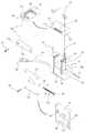
도 1과 도 2는 종래의 전류 및 전압 동시 측정장치를 나타낸 도면이다.
도 3은 본 발명의 전류 및 전압 동시 측정장치를 나타낸 분해사시도이다.
도 4는 본 발명의 전류 및 전압 동시 측정장치를 나타낸 배면사시도이다.
도 5와 도 6은 본 발명의 전류 및 전압 동시 측정장치의 저압선 측정을 위한 작동도이다.FIG. 1 and FIG. 2 are views showing a conventional device for simultaneously measuring a current and a voltage.
3 is an exploded perspective view showing a current and voltage simultaneous measurement apparatus of the present invention.
4 is a rear perspective view showing an apparatus for simultaneously measuring current and voltage of the present invention.
5 and 6 are operational diagrams for low voltage measurement of the current and voltage simultaneous measurement device of the present invention.
이하, 본 발명의 전류 및 전압 동시 측정장치를 도면을 참조하여 상세히 설명한다.Hereinafter, an apparatus for simultaneously measuring a current and a voltage will be described in detail with reference to the drawings.
도 3은 본 발명의 전류 및 전압 동시 측정장치를 나타낸 분해사시도이고, 도 4는 본 발명의 전류 및 전압 동시 측정장치를 나타낸 배면사시도이며, 도 5와 도 6은 본 발명의 전류 및 전압 동시 측정장치의 저압선 측정을 위한 작동도이다.FIG. 3 is an exploded perspective view showing a current and voltage simultaneous measurement apparatus of the present invention, FIG. 4 is a rear perspective view showing a current and voltage simultaneous measurement apparatus of the present invention, and FIGS. 5 and 6 are cross- Fig. 5 is an operation diagram for low-voltage measurement of the device.
본 발명에 의한 전류 및 전압 동시 측정장치(100)는, 본체(110); 탐침(120); 후크(130); 톱니기어(140); 후크용 잠금 및 해정수단(150); 커버(160); 코일; 코어(170); 코어 결합부(180); 케이블 결합부(190); 를 포함하여 이루어진다.An apparatus 100 for simultaneously measuring current and voltage according to the present invention includes a
상기 본체(110)는, 일측면에 저압선(101)의 외주연 일측과 접하여 수용되도록 하며 외측으로 갈수록 폭이 점점 더 넓은 U자형으로 개구된 저압선 수용홈(111)이 형성된다. 상기 본체(110)에는 상기 탐침(120)과 후크(130)와, 톱니기어(140)와, 후크용 잠금 및 해정수단(150) 및 코어(170)가 결합되며, 상기 본체(110)의 내부에는 코일(미도시됨)이 구비되고, 외측에는 코어 결합부(180) 및 케이블 결합부(190)가 구비된다.The
상기 탐침(120)은 상기 본체(110)의 상기 저압선 수용홈(111)의 중앙에 저압선(101)의 길이방향과 수직되게 돌출되게 구비되며 저압선 수용홈(111)에 수용되는 저압선을 천공되도록 하는 역할을 한다. 상기 탐침(120)은 상기 저압선 수용홈(111)에 수용된 저압선(101)을 천공되도록 하여 전기적으로 연결됨으로써 전압을 측정하는데 이용된다.The
상기 후크(130)는, 일측단부가 상기 저압선 수용홈(111)을 기준으로 상기 본체(110)의 일측 상부에 힌지결합되고, 상기 저압선(101)의 외주연 타측과 접하여 상기 저압선 수용홈(111)에 수용된 저압선(101)이 상기 탐침(120)에 천공되도록 회동에 의해 조이도록 하며, 타측 외부에는 다수의 톱니(131)가 형성되고, 상기 저압선 수용홈(111)과 대향되는 U자형상으로 되어 상기 저압선 수용홈(111)과 함께 저압선(101)을 고정되도록 하는 역할을 한다.One end of the
상기 톱니기어(140)는, 일측단부가 상기 저압선 수용홈(111)을 기준으로 상기 본체(110)의 타측 상부에 회전가능하게 구비되고 상기 후크(130)의 톱니(131)와 치합되며 상기 후크(130)의 회동에 의한 조임시 회전되는 역할을 한다. 즉, 상기 톱니기어(140)가 회전되면 상기 톱니기어(140)와 치합되는 상기 후크(130)의 톱니(131)를 이동시켜 상기 후크(130)를 회동시킴으로써 상기 저압선 수용홈(111)에 수용된 저압선을 조이도록 하는 역할을 하게 되는 것이다.The
상기 후크용 잠금 및 해정수단(150)은 상기 후크(130)의 회동된 상태를 유지하거나 상기 후크(130)의 회동이 가능하도록 해정시키는 역할을 한다.The hook locking and unlocking means 150 serves to hold the
상기 후크용 잠금 및 해정수단(150)은 상기 저압선 수용홈(111)에 수용된 저압선(101)이 상기 후크(130)의 회동에 의해 조이게 되는 상태를 잠금으로써 저압선(101)을 고정시키게 된다. 측정이 완료된 후에 상기 후크(130)에 의해 조여진 저압선을 분리시키기 위해서는 상기 후크용 잠금 및 해정수단(150)을 해정시켜 상기 후크(130)를 반대로 회동시킴으로써 저압선(101)의 분리가 가능하게 된다.The hook locking and unlocking means 150 locks the
상기 커버(160)는 상기 본체(110)의 상부에 결합되며 상기 후크(130), 상기 톱니기어(140) 및 상기 후크용 잠금 및 해정수단(150)이 수용되도록 커버하는 역할을 한다.The
상기 코일은 상기 본체(110) 내부에 구비되며 저압선(101)에 흐르는 전류에 의해 유도전류를 검출하는 역할을 한다. 상기 코일은 저압선(101)을 감싸도록 설치되는 후술할 코어(170)로부터 저압선(101)에 흐르는 전류에 비례하는 전압이 유기되게 되며, 유기된 전압은 후술할 케이블(102)로 인출되어 측정되게 된다.The coil is provided inside the
측정원리를 설명하면, 저압선(101)에 전류가 흐르게 되면 자속이 발생되고 발생된 자속이 코어(170)에 유도되게 되며, 코어(170)와 쇄교하여 발생한 상호인덕턴스에 의해 상기 저압선(101)에 흐르는 전류에 비례하는 전압이 코어(170)에 유기되게 된다. 상기 코어(170)에 유기된 전압은 코일을 통해 케이블(102)로 인출되어 전압측정으로 인해 전류가 측정되는 것으로 로고스키(Rogowski) 코일의 원리를 이용하는 것이다.When a current flows through the low-
상기 코어(170)는 상기 코일의 일측과 연결되며 상기 본체(110)의 일측면 외부로 연장되고 단부에 커넥터(171)가 구비되며 상기 코일와 함께 저압선(101)을 감싸도록 하는 것으로, 플렉시블한 형태로 되며 상기 코일의 타측 단부에는 커넥터(171)가 구비된다. 상기 커넥터(171)는 양측에 길이방향으로 길게 형성된 돌기(171a)가 구비된다.The
상기 코어 결합부(180)는 상기 본체(110)의 타측면에 구비되고, 상기 코일의 타측 단부에 구비된 커넥터(171)와 연결되어 상기 코어(170)가 저압선(101)을 감싸는 형태가 되도록 한다. 상기 코어 결합부(180)의 내주연에는 상기 커넥터(171)에 구비된 돌기(171a)가 삽입결합되는 돌기삽입홈(미도시됨)이 구비된다.The
상기 코어 결합부(180)의 돌기삽입홈에 상기 커넥터(171)에 구비된 돌기(171a)가 삽입됨으로써 상기 코어 결합부(180)에 상기 커넥터(171)가 삽입되어 상기 코어(170)가 결합되게 된다.The
이때, 상기 코어 결합부(180)에 결합된 상기 코어(170)가 결합된 상태로 고정되도록 하기 위해, 상기 코어 결합부(180)의 외주연에는 커넥터 고정부(185)가 구비된다.At this time, the
상기 커넥터 고정부(185)는 상기 코어 결합부(180)의 외주연에 일정각도 회전가능하게 결합되며 회전에 의해 삽입된 돌기(171a)가 걸려 커넥터(171)가 상기 코어 결합부(180)로부터 분리되는 것을 방지하는 역할을 하게 된다.The
상기 케이블 결합부(190)는, 상기 본체(110)에 구비되며 상기 코일과 상기 탐침(120)과 연결되어 검출된 유도전류 및 전압을 인출하는 케이블(102)이 결합된다. 상기 케이블(102)은 분석기(미도시됨)와 연결되어 저압선에 흐르는 전류 및 전압을 분석하여 표시하게 된다.The
상기와 같은 구성으로 된 본 발명의 전류 및 전압 동시 측정장치의 전류 및 전압측정을 위해 다음과 같이 저압선을 본체에 고정시키게 된다.In order to measure the current and voltage of the apparatus for simultaneously measuring current and voltage of the present invention having the above-described configuration, a low-voltage line is fixed to a main body as follows.
먼저, 저압선(101)을 상기 본체(110)의 저압선 수용홈(111)에 도 5에서와 같이 거치시키고 상기 후크(130)를 회동시켜 도 6과 같은 상태로 한 다음, 톱니기어(140)의 톱니기어 회전용 돌기(141)에 공구를 삽입하여 회전시키게 되면 후크(130)가 저압선 수용홈(111)에 근접됨으로써 상기 후크(130)가 저압선 수용홈(111)에 수용된 저압선(101)의 외측을 조이게 됨으로써 저압선(101)이 저압선 수용홈(111)과 후크(130)에 의해 고정되게 된다.5, the low-
또한, 코어(170)의 타측 단부에 구비된 커넥터(171)를 코어 결합부(180)에 삽입하여 코어(170)가 저압선(101)을 감싸는 형태가 되도록 하면 전류 및 전압 측정을 위한 세팅이 완료되게 된다.When the
이와 같이 본 발명은, 본체와 상부덮개의 결합 및 분리되도록 하여 측정하는 종래의 장치와는 달리, 저압선을 고정하는 후크를 회동식으로 구비하고 탐침을 회전시키지 않고 후크를 타이트하게 고정되도록 하여 탐침이 저압선을 천공되도록 하므로 저압선의 전압측정을 위한 설치가 매우 용이한 장점이 있다. 아울러, 후크로 저압선을 타이트하게 본체에 고정시키는 것만으로 전압측정을 위한 세팅이 완료되므로 측정시간을 줄일 수 있게 된다.As described above, unlike the conventional apparatus in which the main body and the upper cover are combined and separated, the hook is fixed on the hook for fixing the low-tension wire, and the hook is tightly fixed without rotating the probe, Since the low-voltage line is perforated, it is very easy to install for measuring the voltage of the low-voltage line. In addition, since the setting for the voltage measurement is completed by fixing the low-voltage line tightly to the main body with the hook, the measurement time can be reduced.
또한, 상부덮개에 구비되는 상부코어를 너트를 이용하여 본체에 결합되도록 하는 종래의 장치와는 달리, 코어를 플렉시블한 전선형태로 구비하고 코어의 단부를 분리가능한 커넥터형태로 구비하여 코어를 구부려 단부를 본체에 간단한 삽입결합으로 코어가 저압선을 감싸도록 설치하게 되므로 전류 측정을 위한 설치가 매우 용이하므로 측정시간을 단축할 수 있게 된다.Unlike the conventional device in which the upper core provided on the upper cover is coupled to the main body by using a nut, the core is provided in a flexible wire form and the end portion of the core is removable, Since the core is installed so as to surround the low-voltage line by simple insertion of the main body into the main body, the measurement time can be shortened because the installation for measuring the current is very easy.
또한, 저압선의 직경에 제한이 있는 종래의 장치와는 달리 후크로 고정할 수 있는 저압선의 직경의 크기가 크므로 저압선의 직경이 크더라도 측정이 가능한 장점이 있다.In addition, unlike the conventional apparatus having a limited diameter of the low-voltage line, since the diameter of the low-voltage line fixed by the hook is large, measurement is possible even if the diameter of the low-voltage line is large.
본 발명의 상기 후크용 잠금 및 해정수단(150)은, 상기 톱니기어(140)와 인접하도록 설치되며, 힌지결합부(151)와 걸림부(152) 및 해정손잡이부(153)로 이루어진다.The hook locking and unlocking means 150 of the present invention is installed adjacent to the
상기 힌지결합부(151)는 중앙부위에 상기 본체(110)의 상부에 회동가능하게 결합된다.The hinge engaging portion 151 is rotatably coupled to an upper portion of the
상기 걸림부(152)는 내측단부에 구비되며 상기 후크(130)의 회동에 의한 저압선(101) 조임시 상기 톱니(131)에 걸려 상기 후크(130)의 회동에 의한 저압선(101) 조임을 유지하는 역할을 한다.The hook portion 152 is provided at the inner end portion and is engaged with the
상기 해정손잡이부(153)는 타측단부에 구비되고 상기 본체(110) 외부로 돌출되며 회동에 의해 상기 후크(130)의 상기 톱니(131)로부터 상기 걸림부(152)가 이격되도록 하여 상기 후크(130)의 회동이 가능하도록 해정시키는 역할을 한다.The
아울러, 상기 후크용 잠금 및 해정수단(150)은, 상기 톱니(131)에 상기 걸림부(152)가 걸린 상태를 유지시키도록 탄지시키는 탄지스프링(154)이 더 구비된 것이 바람직하다.It is preferable that the hook locking and unlocking means 150 further include a
상기 탄지스프링(154)은 상기 톱니(131)에 상기 걸림부(152)가 걸린 상태를 유지시키도록 탄지되어 상기 후크용 잠금 및 해정수단(150)이 잠김상태를 유지하게 된다.The
또한, 상기 톱니기어(140)의 상부에는 상기 커버(160) 외부로 노출되도록 형성되며 공구에 의해 상기 톱니기어(140)를 회전시킴으로써 상기 후크(130)에 의한 저압선(101)의 조임력을 부가시키는 톱니기어 회전용 돌기(141)가 구비된 것이 바람직하다.The
상기 톱니기어 회전용 돌기(141)는 상기 톱니기어(140)를 회전시키기 위한 것으로 상기 톱니기어(140)를 회전시킴으로써 상기 톱니기어(140)와 치합되는 상기 후크(130)에 구비된 톱니(131)를 이동시킴으로써 상기 후크(130)가 회동되어 상기 후크(130)가 상기 저압선 수용홈(111)과 함께 저압선(101)을 고정시키게 되는 것이다.The toothed gear rotation protrusion 141 is for rotating the
상기 커버(160)에는 상기 커버(160)의 상부로 상기 톱니기어 회전용 돌기(141)가 노출되도록 하기 위한 돌기 노출공(161)이 형성된다.The
본 발명의 상기한 실시예에 한정하여 기술적 사상을 해석해서는 안된다. 적용범위가 다양함은 물론이고, 청구범위에서 청구하는 본 발명의 요지를 벗어남이 없이 당업자의 수준에서 다양한 변형 실시가 가능하다. 따라서 이러한 개량 및 변경은 당업자에게 자명한 것인 한 본 발명의 보호범위에 속하게 된다.The technical idea should not be interpreted as being limited to the above-described embodiment of the present invention. It will be understood by those skilled in the art that various changes in form and details may be made therein without departing from the spirit and scope of the invention as defined by the appended claims. Accordingly, such modifications and changes are within the scope of protection of the present invention as long as it is obvious to those skilled in the art.
101 : 저압선110 : 본체111 : 저압선 수용홈
120 : 탐침130 : 후크131 : 톱니
140 : 톱니기어141 : 톱니기어 회전용 돌기
150 : 후크용 잠금 및 해정수단151 : 힌지결합부
152 : 걸림부153 : 해정손잡이부154 : 탄지스프링
160 : 커버161 : 돌기 노출공170 : 코어
171 : 커넥터180 : 코어 결합부190 : 케이블 결합부101: low-voltage line 110: main body 111: low-
120: probe 130: hook 131: tooth
140: Toothed gear 141: Toothed gear rotation projection
150: locking and unlocking means for the hook 151:
152: engaging part 153: unlocking grip part 154:
160: Cover 161: Projection exposure hole 170: Core
171: connector 180: core coupling portion 190: cable coupling portion
Claims (4)
Translated fromKorean상기 본체(110)의 상기 저압선 수용홈(111)의 중앙에 저압선(101)의 길이방향과 수직되게 돌출되게 구비되며 상기 저압선 수용홈(111)에 수용되는 저압선을 천공되도록 하는 탐침(120);
일측단부가 상기 저압선 수용홈(111)을 기준으로 상기 본체(110)의 일측 상부에 힌지결합되고, 상기 저압선(101)의 외주연 타측과 접하여 상기 저압선 수용홈(111)에 수용된 저압선(101)이 상기 탐침(120)에 천공되도록 회동에 의해 조이도록 하며, 타측 외부에는 다수의 톱니(131)가 형성되고, U자형상으로 된 후크(130);
일측단부가 상기 저압선 수용홈(111)을 기준으로 상기 본체(110)의 타측 상부에 회전가능하게 구비되고 상기 후크(130)의 톱니(131)와 치합되며 상기 후크(130)의 회동에 의한 조임시 회전되는 톱니기어(140);
상기 후크(130)의 회동된 상태를 유지하거나 상기 후크(130)의 회동이 가능하도록 해정시키는 후크용 잠금 및 해정수단(150);
상기 본체(110)의 상부에 결합되며 상기 후크(130), 상기 톱니기어(140) 및 상기 후크용 잠금 및 해정수단(150)이 수용되도록 커버하는 커버(160);
상기 본체(110) 내부에 구비되며 저압선(101)에 흐르는 전류에 의해 유도전류를 검출하는 코일;
상기 코일의 일측과 연결되며 상기 본체(110)의 일측면 외부로 연장되고 단부에 커넥터(171)가 구비되며 상기 코일와 함께 저압선(101)을 감싸도록 하는 플렉시블한 코어(170);
상기 코일의 타측과 연결되며 상기 본체(110)의 타측면에 구비되고 상기 코어(170)의 커넥터(171)와 결합되는 코어 결합부(180);
상기 본체(110)에 구비되며 상기 코일과 상기 탐침(120)과 연결되어 검출된 유도전류 및 전압을 인출하는 케이블(102)이 결합되는 케이블 결합부(190);
를 포함하여 이루어지는 것을 특징으로 하는 전류 및 전압 동시 측정장치.A main body 110 formed on one side thereof with a low-voltage line receiving groove 111 opened to be received in contact with the outer peripheral side of the low-voltage line 101 and having a U-shaped opening gradually wider toward the outside;
A probe 120 protruding from a center of the low-voltage line receiving groove 111 of the main body 110 so as to be perpendicular to a longitudinal direction of the low-voltage line 101 and penetrating a low-voltage line received in the low-voltage line receiving groove 111;
A low voltage line 101 housed in the low voltage line receiving groove 111 and hinged to an upper portion of one side of the main body 110 with one end of the low voltage line receiving groove 111 as a reference, A plurality of teeth 131 are formed on the outer side of the probe 120 to pierce the probe 120 by pivoting, and a U-shaped hook 130 is formed.
One end of which is rotatably provided on the other side of the other side of the main body 110 with respect to the low-voltage wire receiving groove 111, is engaged with the teeth 131 of the hook 130, and fastened by the rotation of the hook 130 A toothed gear 140 rotated at a time;
A hook locking and unlocking means (150) for holding the hooked state of the hook (130) or allowing the hook (130) to pivot;
A cover 160 coupled to an upper portion of the main body 110 to cover the hook 130, the gear 140, and the locking and unlocking means 150 for the hook.
A coil provided inside the body 110 and detecting an induced current by a current flowing in the low-voltage line 101;
A flexible core 170 connected to one side of the coil and extending outwardly from one side of the main body 110 and having a connector 171 at its end and surrounding the low-voltage line 101 with the coil;
A core coupling portion 180 connected to the other side of the coil and disposed on the other side of the main body 110 and coupled to the connector 171 of the core 170;
A cable coupling part 190 provided in the main body 110 and connected to the coil and the probe 120 to couple a cable 102 for extracting a detected induced current and voltage;
And a voltage measuring unit for measuring a voltage of the current and voltage.
상기 후크용 잠금 및 해정수단(150)은,
상기 톱니기어(140)와 인접하도록 설치되며, 중앙부위에 상기 본체(110)의 상부에 회동가능하게 결합되는 힌지결합부(151)가 구비되고, 내측단부에는 상기 후크(130)의 회동에 의한 저압선(101) 조임시 상기 톱니(131)에 걸려 상기 후크(130)의 회동에 의한 저압선(101) 조임을 유지하는 걸림부(152)가 구비되고, 타측단부에는 상기 본체(110) 외부로 돌출되며 회동에 의해 상기 후크(130)의 상기 톱니(131)로부터 상기 걸림부(152)가 이격되도록 하여 상기 후크(130)의 회동이 가능하도록 해정시키는 해정손잡이부(153)가 구비된 것을 특징으로 하는 전류 및 전압 동시 측정장치.The method according to claim 1,
The hook locking and unlocking means (150)
And a hinge engaging portion 151 which is installed adjacent to the gear 140 and is rotatably coupled to the upper portion of the main body 110 at a central portion thereof. A hook portion 152 for hooking the sawtooth 131 when the low-tension wire 101 is fastened and for holding the low-tension wire 101 by the rotation of the hook 130 is provided, and at the other end, And a release handle 153 for releasing the hook 130 from the teeth 131 of the hook 130 by rotating the hook 130 so that the hook 130 can be rotated. A device for simultaneous measurement of current and voltage.
상기 후크용 잠금 및 해정수단(150)은, 상기 톱니(131)에 상기 걸림부(152)가 걸린 상태를 유지시키도록 탄지시키는 탄지스프링(154)이 더 구비된 것을 특징으로 하는 전류 및 전압 동시 측정장치.3. The method of claim 2,
Wherein the hook locking and unlocking means (150) further comprises a tangential spring (154) for urging the toothed portion (131) to retain the engagement portion (152) Measuring device.
상기 톱니기어(140)의 상부에는 상기 커버(160) 외부로 노출되도록 형성되며 공구에 의해 상기 톱니기어(140)를 회전시킴으로써 상기 후크(130)에 의한 저압선(101)의 조임력을 부가시키는 톱니기어 회전용 돌기(141)가 구비된 것을 특징으로 하는 전류 및 전압 동시 측정장치.The method according to claim 1,
The saw gear 140 is formed to be exposed to the outside of the cover 160 and rotates the toothed gear 140 by means of a tool to thereby apply a tightening force of the low- And a rotation protrusion (141) is provided on the surface of the rotating body.
Priority Applications (1)
| Application Number | Priority Date | Filing Date | Title |
|---|---|---|---|
| KR1020170059189AKR101895719B1 (en) | 2017-05-12 | 2017-05-12 | Simultaneous Measurement Apparatus of Current and Voltage |
Applications Claiming Priority (1)
| Application Number | Priority Date | Filing Date | Title |
|---|---|---|---|
| KR1020170059189AKR101895719B1 (en) | 2017-05-12 | 2017-05-12 | Simultaneous Measurement Apparatus of Current and Voltage |
Publications (1)
| Publication Number | Publication Date |
|---|---|
| KR101895719B1true KR101895719B1 (en) | 2018-09-05 |
Family
ID=63594550
Family Applications (1)
| Application Number | Title | Priority Date | Filing Date |
|---|---|---|---|
| KR1020170059189AExpired - Fee RelatedKR101895719B1 (en) | 2017-05-12 | 2017-05-12 | Simultaneous Measurement Apparatus of Current and Voltage |
Country Status (1)
| Country | Link |
|---|---|
| KR (1) | KR101895719B1 (en) |
Cited By (4)
| Publication number | Priority date | Publication date | Assignee | Title |
|---|---|---|---|---|
| CN109813940A (en)* | 2019-02-20 | 2019-05-28 | 山东元星电子有限公司 | Openable clamping support of flexible Roche coil and opening and closing method thereof |
| CN114341654A (en)* | 2019-08-20 | 2022-04-12 | 莱姆国际股份有限公司 | ROGOWSKI current sensor |
| US20230402825A1 (en)* | 2020-10-08 | 2023-12-14 | Ubicquia, Inc. | Apparatus for positioning and retaining a cable-styled device around an object |
| EP4145141B1 (en)* | 2021-09-02 | 2024-10-30 | Fluke Corporation | Sensor probe with combined non-contact sensor and a rogowski coil |
Citations (4)
| Publication number | Priority date | Publication date | Assignee | Title |
|---|---|---|---|---|
| KR20040081585A (en)* | 2003-03-14 | 2004-09-22 | 주식회사 포러스테크놀로지 | The electric power voltage/current measuring probe for low voltage distribution power line |
| KR20110000017U (en)* | 2009-06-26 | 2011-01-03 | 손정아 | The electric voltage measuring probe |
| KR101256654B1 (en)* | 2012-02-06 | 2013-04-19 | 주식회사 아이바 | Probe for load measurement |
| KR101468887B1 (en)* | 2013-09-13 | 2014-12-05 | 오찬배 | Probe for measuring electric power load |
- 2017
- 2017-05-12KRKR1020170059189Apatent/KR101895719B1/ennot_activeExpired - Fee Related
Patent Citations (4)
| Publication number | Priority date | Publication date | Assignee | Title |
|---|---|---|---|---|
| KR20040081585A (en)* | 2003-03-14 | 2004-09-22 | 주식회사 포러스테크놀로지 | The electric power voltage/current measuring probe for low voltage distribution power line |
| KR20110000017U (en)* | 2009-06-26 | 2011-01-03 | 손정아 | The electric voltage measuring probe |
| KR101256654B1 (en)* | 2012-02-06 | 2013-04-19 | 주식회사 아이바 | Probe for load measurement |
| KR101468887B1 (en)* | 2013-09-13 | 2014-12-05 | 오찬배 | Probe for measuring electric power load |
Cited By (5)
| Publication number | Priority date | Publication date | Assignee | Title |
|---|---|---|---|---|
| CN109813940A (en)* | 2019-02-20 | 2019-05-28 | 山东元星电子有限公司 | Openable clamping support of flexible Roche coil and opening and closing method thereof |
| CN114341654A (en)* | 2019-08-20 | 2022-04-12 | 莱姆国际股份有限公司 | ROGOWSKI current sensor |
| CN114341654B (en)* | 2019-08-20 | 2024-02-06 | 莱姆国际股份有限公司 | ROGOWSKI current sensor |
| US20230402825A1 (en)* | 2020-10-08 | 2023-12-14 | Ubicquia, Inc. | Apparatus for positioning and retaining a cable-styled device around an object |
| EP4145141B1 (en)* | 2021-09-02 | 2024-10-30 | Fluke Corporation | Sensor probe with combined non-contact sensor and a rogowski coil |
Similar Documents
| Publication | Publication Date | Title |
|---|---|---|
| KR101895719B1 (en) | Simultaneous Measurement Apparatus of Current and Voltage | |
| JP7657858B2 (en) | Electrical parameter sensor probe and method for detecting an electrical parameter in an insulated conductor - Patents.com | |
| JP7159106B2 (en) | Clamp probe for non-contact electrical parameter measurement | |
| JP5039778B2 (en) | Electrical measuring instrument with detachable current clamp | |
| US5180972A (en) | Housing including biasing springs extending between clamp arms for cable mounted power line monitoring device | |
| JPH087614Y2 (en) | Wire cap | |
| US6043433A (en) | Cable clamp with universal positioning | |
| US20210239740A1 (en) | Non-contact voltage measurement with adjustable size rogowski coil | |
| JP5756607B2 (en) | Current measuring device and method for detecting conversion rate of current sensor | |
| JPH09318674A (en) | Simple photocurrent meter | |
| US20050127895A1 (en) | Current sensor wire clamp | |
| CN218445716U (en) | Novel ground resistance tester | |
| JP4551629B2 (en) | Current sensor | |
| CN207817046U (en) | A kind of cable termination earth current measuring device | |
| CN209913074U (en) | Jointing clamp | |
| CN213302307U (en) | Direct current method detector for wiring of main transformer bushing current transformer | |
| JP5366365B2 (en) | Probe storage device that can be attached to an insulation resistance measuring instrument | |
| JP4721636B2 (en) | Attaching and removing the high-voltage hot-wire ammeter | |
| CN112484602B (en) | Check out test set is used in cable conductor manufacturing | |
| CN115343522A (en) | Clamp on ammeter | |
| JP4164259B2 (en) | Clamp on sensor | |
| JP2536668Y2 (en) | Clamp type measuring instrument | |
| JP3769383B2 (en) | Test lead rod holding structure in clamp-type ammeter | |
| JPH0575982B2 (en) |
Legal Events
| Date | Code | Title | Description |
|---|---|---|---|
| PA0109 | Patent application | St.27 status event code:A-0-1-A10-A12-nap-PA0109 | |
| PA0201 | Request for examination | St.27 status event code:A-1-2-D10-D11-exm-PA0201 | |
| P11-X000 | Amendment of application requested | St.27 status event code:A-2-2-P10-P11-nap-X000 | |
| P13-X000 | Application amended | St.27 status event code:A-2-2-P10-P13-nap-X000 | |
| D13-X000 | Search requested | St.27 status event code:A-1-2-D10-D13-srh-X000 | |
| D14-X000 | Search report completed | St.27 status event code:A-1-2-D10-D14-srh-X000 | |
| PE0902 | Notice of grounds for rejection | St.27 status event code:A-1-2-D10-D21-exm-PE0902 | |
| P11-X000 | Amendment of application requested | St.27 status event code:A-2-2-P10-P11-nap-X000 | |
| P13-X000 | Application amended | St.27 status event code:A-2-2-P10-P13-nap-X000 | |
| PE0701 | Decision of registration | St.27 status event code:A-1-2-D10-D22-exm-PE0701 | |
| GRNT | Written decision to grant | ||
| PR0701 | Registration of establishment | St.27 status event code:A-2-4-F10-F11-exm-PR0701 | |
| PR1002 | Payment of registration fee | St.27 status event code:A-2-2-U10-U11-oth-PR1002 Fee payment year number:1 | |
| PG1601 | Publication of registration | St.27 status event code:A-4-4-Q10-Q13-nap-PG1601 | |
| PR1001 | Payment of annual fee | St.27 status event code:A-4-4-U10-U11-oth-PR1001 Fee payment year number:4 | |
| PC1903 | Unpaid annual fee | St.27 status event code:A-4-4-U10-U13-oth-PC1903 Not in force date:20220831 Payment event data comment text:Termination Category : DEFAULT_OF_REGISTRATION_FEE | |
| PC1903 | Unpaid annual fee | St.27 status event code:N-4-6-H10-H13-oth-PC1903 Ip right cessation event data comment text:Termination Category : DEFAULT_OF_REGISTRATION_FEE Not in force date:20220831 |