KR101893665B1 - Wiring harness for an aerial vehicle - Google Patents
Wiring harness for an aerial vehicleDownload PDFInfo
- Publication number
- KR101893665B1 KR101893665B1KR1020167017188AKR20167017188AKR101893665B1KR 101893665 B1KR101893665 B1KR 101893665B1KR 1020167017188 AKR1020167017188 AKR 1020167017188AKR 20167017188 AKR20167017188 AKR 20167017188AKR 101893665 B1KR101893665 B1KR 101893665B1
- Authority
- KR
- South Korea
- Prior art keywords
- connector
- wing
- wire
- wiring harness
- Prior art date
- Legal status (The legal status is an assumption and is not a legal conclusion. Google has not performed a legal analysis and makes no representation as to the accuracy of the status listed.)
- Expired - Fee Related
Links
Images


Classifications
- B—PERFORMING OPERATIONS; TRANSPORTING
- B64—AIRCRAFT; AVIATION; COSMONAUTICS
- B64C—AEROPLANES; HELICOPTERS
- B64C39/00—Aircraft not otherwise provided for
- B64C39/02—Aircraft not otherwise provided for characterised by special use
- B—PERFORMING OPERATIONS; TRANSPORTING
- B64—AIRCRAFT; AVIATION; COSMONAUTICS
- B64U—UNMANNED AERIAL VEHICLES [UAV]; EQUIPMENT THEREFOR
- B64U10/00—Type of UAV
- B64U10/60—Tethered aircraft
- B—PERFORMING OPERATIONS; TRANSPORTING
- B64—AIRCRAFT; AVIATION; COSMONAUTICS
- B64C—AEROPLANES; HELICOPTERS
- B64C3/00—Wings
- B64C3/26—Construction, shape, or attachment of separate skins, e.g. panels
- B—PERFORMING OPERATIONS; TRANSPORTING
- B64—AIRCRAFT; AVIATION; COSMONAUTICS
- B64C—AEROPLANES; HELICOPTERS
- B64C39/00—Aircraft not otherwise provided for
- B64C39/02—Aircraft not otherwise provided for characterised by special use
- B64C39/022—Tethered aircraft
- B—PERFORMING OPERATIONS; TRANSPORTING
- B64—AIRCRAFT; AVIATION; COSMONAUTICS
- B64U—UNMANNED AERIAL VEHICLES [UAV]; EQUIPMENT THEREFOR
- B64U10/00—Type of UAV
- B64U10/25—Fixed-wing aircraft
- B—PERFORMING OPERATIONS; TRANSPORTING
- B64—AIRCRAFT; AVIATION; COSMONAUTICS
- B64U—UNMANNED AERIAL VEHICLES [UAV]; EQUIPMENT THEREFOR
- B64U30/00—Means for producing lift; Empennages; Arrangements thereof
- B64U30/10—Wings
- B—PERFORMING OPERATIONS; TRANSPORTING
- B64—AIRCRAFT; AVIATION; COSMONAUTICS
- B64U—UNMANNED AERIAL VEHICLES [UAV]; EQUIPMENT THEREFOR
- B64U50/00—Propulsion; Power supply
- B64U50/10—Propulsion
- B64U50/13—Propulsion using external fans or propellers
- B—PERFORMING OPERATIONS; TRANSPORTING
- B64—AIRCRAFT; AVIATION; COSMONAUTICS
- B64U—UNMANNED AERIAL VEHICLES [UAV]; EQUIPMENT THEREFOR
- B64U50/00—Propulsion; Power supply
- B64U50/30—Supply or distribution of electrical power
- B64U50/34—In-flight charging
- B64U50/36—In-flight charging by wind turbines, e.g. ram air turbines [RAT]
- F—MECHANICAL ENGINEERING; LIGHTING; HEATING; WEAPONS; BLASTING
- F03—MACHINES OR ENGINES FOR LIQUIDS; WIND, SPRING, OR WEIGHT MOTORS; PRODUCING MECHANICAL POWER OR A REACTIVE PROPULSIVE THRUST, NOT OTHERWISE PROVIDED FOR
- F03D—WIND MOTORS
- F03D5/00—Other wind motors
- H—ELECTRICITY
- H01—ELECTRIC ELEMENTS
- H01R—ELECTRICALLY-CONDUCTIVE CONNECTIONS; STRUCTURAL ASSOCIATIONS OF A PLURALITY OF MUTUALLY-INSULATED ELECTRICAL CONNECTING ELEMENTS; COUPLING DEVICES; CURRENT COLLECTORS
- H01R43/00—Apparatus or processes specially adapted for manufacturing, assembling, maintaining, or repairing of line connectors or current collectors or for joining electric conductors
- H01R43/02—Apparatus or processes specially adapted for manufacturing, assembling, maintaining, or repairing of line connectors or current collectors or for joining electric conductors for soldered or welded connections
- H—ELECTRICITY
- H01—ELECTRIC ELEMENTS
- H01R—ELECTRICALLY-CONDUCTIVE CONNECTIONS; STRUCTURAL ASSOCIATIONS OF A PLURALITY OF MUTUALLY-INSULATED ELECTRICAL CONNECTING ELEMENTS; COUPLING DEVICES; CURRENT COLLECTORS
- H01R43/00—Apparatus or processes specially adapted for manufacturing, assembling, maintaining, or repairing of line connectors or current collectors or for joining electric conductors
- H01R43/04—Apparatus or processes specially adapted for manufacturing, assembling, maintaining, or repairing of line connectors or current collectors or for joining electric conductors for forming connections by deformation, e.g. crimping tool
- H—ELECTRICITY
- H01—ELECTRIC ELEMENTS
- H01R—ELECTRICALLY-CONDUCTIVE CONNECTIONS; STRUCTURAL ASSOCIATIONS OF A PLURALITY OF MUTUALLY-INSULATED ELECTRICAL CONNECTING ELEMENTS; COUPLING DEVICES; CURRENT COLLECTORS
- H01R43/00—Apparatus or processes specially adapted for manufacturing, assembling, maintaining, or repairing of line connectors or current collectors or for joining electric conductors
- H01R43/20—Apparatus or processes specially adapted for manufacturing, assembling, maintaining, or repairing of line connectors or current collectors or for joining electric conductors for assembling or disassembling contact members with insulating base, case or sleeve
- H—ELECTRICITY
- H02—GENERATION; CONVERSION OR DISTRIBUTION OF ELECTRIC POWER
- H02G—INSTALLATION OF ELECTRIC CABLES OR LINES, OR OF COMBINED OPTICAL AND ELECTRIC CABLES OR LINES
- H02G3/00—Installations of electric cables or lines or protective tubing therefor in or on buildings, equivalent structures or vehicles
- H02G3/02—Details
- H02G3/04—Protective tubing or conduits, e.g. cable ladders or cable troughs
- H02G3/0406—Details thereof
- B—PERFORMING OPERATIONS; TRANSPORTING
- B64—AIRCRAFT; AVIATION; COSMONAUTICS
- B64U—UNMANNED AERIAL VEHICLES [UAV]; EQUIPMENT THEREFOR
- B64U2101/00—UAVs specially adapted for particular uses or applications
- B64U2101/10—UAVs specially adapted for particular uses or applications for generating power to be supplied to a remote station, e.g. UAVs with solar panels
- B—PERFORMING OPERATIONS; TRANSPORTING
- B64—AIRCRAFT; AVIATION; COSMONAUTICS
- B64U—UNMANNED AERIAL VEHICLES [UAV]; EQUIPMENT THEREFOR
- B64U2201/00—UAVs characterised by their flight controls
- B64U2201/20—Remote controls
- B64U2201/202—Remote controls using tethers for connecting to ground station
- F—MECHANICAL ENGINEERING; LIGHTING; HEATING; WEAPONS; BLASTING
- F05—INDEXING SCHEMES RELATING TO ENGINES OR PUMPS IN VARIOUS SUBCLASSES OF CLASSES F01-F04
- F05B—INDEXING SCHEME RELATING TO WIND, SPRING, WEIGHT, INERTIA OR LIKE MOTORS, TO MACHINES OR ENGINES FOR LIQUIDS COVERED BY SUBCLASSES F03B, F03D AND F03G
- F05B2240/00—Components
- F05B2240/90—Mounting on supporting structures or systems
- F05B2240/91—Mounting on supporting structures or systems on a stationary structure
- F05B2240/917—Mounting on supporting structures or systems on a stationary structure attached to cables
- F—MECHANICAL ENGINEERING; LIGHTING; HEATING; WEAPONS; BLASTING
- F05—INDEXING SCHEMES RELATING TO ENGINES OR PUMPS IN VARIOUS SUBCLASSES OF CLASSES F01-F04
- F05B—INDEXING SCHEME RELATING TO WIND, SPRING, WEIGHT, INERTIA OR LIKE MOTORS, TO MACHINES OR ENGINES FOR LIQUIDS COVERED BY SUBCLASSES F03B, F03D AND F03G
- F05B2240/00—Components
- F05B2240/90—Mounting on supporting structures or systems
- F05B2240/92—Mounting on supporting structures or systems on an airbourne structure
- F05B2240/921—Mounting on supporting structures or systems on an airbourne structure kept aloft due to aerodynamic effects
- Y—GENERAL TAGGING OF NEW TECHNOLOGICAL DEVELOPMENTS; GENERAL TAGGING OF CROSS-SECTIONAL TECHNOLOGIES SPANNING OVER SEVERAL SECTIONS OF THE IPC; TECHNICAL SUBJECTS COVERED BY FORMER USPC CROSS-REFERENCE ART COLLECTIONS [XRACs] AND DIGESTS
- Y02—TECHNOLOGIES OR APPLICATIONS FOR MITIGATION OR ADAPTATION AGAINST CLIMATE CHANGE
- Y02E—REDUCTION OF GREENHOUSE GAS [GHG] EMISSIONS, RELATED TO ENERGY GENERATION, TRANSMISSION OR DISTRIBUTION
- Y02E10/00—Energy generation through renewable energy sources
- Y02E10/70—Wind energy
- Y02E10/72—Wind turbines with rotation axis in wind direction
- Y—GENERAL TAGGING OF NEW TECHNOLOGICAL DEVELOPMENTS; GENERAL TAGGING OF CROSS-SECTIONAL TECHNOLOGIES SPANNING OVER SEVERAL SECTIONS OF THE IPC; TECHNICAL SUBJECTS COVERED BY FORMER USPC CROSS-REFERENCE ART COLLECTIONS [XRACs] AND DIGESTS
- Y02—TECHNOLOGIES OR APPLICATIONS FOR MITIGATION OR ADAPTATION AGAINST CLIMATE CHANGE
- Y02E—REDUCTION OF GREENHOUSE GAS [GHG] EMISSIONS, RELATED TO ENERGY GENERATION, TRANSMISSION OR DISTRIBUTION
- Y02E10/00—Energy generation through renewable energy sources
- Y02E10/70—Wind energy
- Y02E10/728—Onshore wind turbines
- Y—GENERAL TAGGING OF NEW TECHNOLOGICAL DEVELOPMENTS; GENERAL TAGGING OF CROSS-SECTIONAL TECHNOLOGIES SPANNING OVER SEVERAL SECTIONS OF THE IPC; TECHNICAL SUBJECTS COVERED BY FORMER USPC CROSS-REFERENCE ART COLLECTIONS [XRACs] AND DIGESTS
- Y10—TECHNICAL SUBJECTS COVERED BY FORMER USPC
- Y10T—TECHNICAL SUBJECTS COVERED BY FORMER US CLASSIFICATION
- Y10T29/00—Metal working
- Y10T29/49—Method of mechanical manufacture
- Y10T29/49002—Electrical device making
- Y10T29/49117—Conductor or circuit manufacturing
- Y10T29/49174—Assembling terminal to elongated conductor
- Y10T29/49176—Assembling terminal to elongated conductor with molding of electrically insulating material
Landscapes
- Engineering & Computer Science (AREA)
- Aviation & Aerospace Engineering (AREA)
- Mechanical Engineering (AREA)
- Chemical & Material Sciences (AREA)
- Combustion & Propulsion (AREA)
- Life Sciences & Earth Sciences (AREA)
- Sustainable Development (AREA)
- Sustainable Energy (AREA)
- Remote Sensing (AREA)
- Manufacturing & Machinery (AREA)
- General Engineering & Computer Science (AREA)
- Structural Engineering (AREA)
- Civil Engineering (AREA)
- Architecture (AREA)
- Wind Motors (AREA)
- Insulated Conductors (AREA)
- Communication Cables (AREA)
Abstract
Translated fromKoreanDescription
Translated fromKorean관련 출원의 상호 참조Cross reference of related application
본원은 2013년 12월 30일자로 출원된 미국 특허 출원 제14/143,543호에 대해 우선권을 주장하며, 따라서 그 전체가 참고로 포함된다.Priority is claimed on U.S. Patent Application No. 14 / 143,543, filed December 30, 2013, which is hereby incorporated by reference in its entirety.
본 명세서에서 달리 표시되지 않는 한, 본 섹션에서 설명되는 내용들은 본 명세서의 청구항들에 대한 종래 기술이 아니며, 본 섹션의 포함에 의해 종래 기술인 것으로 인정되지 않는다.Unless otherwise indicated herein, the contents set forth in this section are not prior art to the claims of this specification and are not to be construed as prior art by the inclusion of this section.
풍력은 재생 가능 에너지의 소스이다. 전통적으로, 풍력 에너지는 돛의 사용을 통해 워터크래프트 또는 랜드 크래프트를 견인하는 데 사용되어 왔다. 그러나, 돛은 통상적으로 지면에 가깝게 배치되며, 더 높은 고도에서 더 강한 풍력을 이용하지 못한다. 비행체들이 그러한 더 높은 고도에서 풍력으로부터 전력을 추출하여 발전기를 돌리는 데 사용될 수 있다. 그러한 비행체들은 전력을 다양한 컴포넌트들로 전달하기 위한 회로를 갖는 하나 이상의 날개를 포함한다.Wind power is the source of renewable energy. Traditionally, wind energy has been used to tow watercrafts or landcrafts through the use of sails. However, the sails are typically placed close to the ground and do not utilize stronger wind forces at higher altitudes. Air vehicles can be used to extract power from wind power at such a higher altitude and drive the generator. Such air vehicles include one or more vanes having circuitry for delivering power to the various components.
발명의 요약SUMMARY OF THE INVENTION
본 명세서에서는 비행체용 와이어링 하니스를 제공하기 위한 시스템들 및 방법들이 설명된다. 본 명세서에서 설명되는 실시예들은 비행체의 날개에 부착된 하니스 상의 컴포넌트들에 급전하기 위한 와이어링을 제공한다. 날개의 보호 외부층을 통해 구멍 등을 형성할 필요를 없앰으로써, 그러한 하니스는 날개의 무결성을 유지하고, 따라서 날개의 유효 수명을 연장할 수 있다.Systems and methods for providing a wiring harness for aviation are described herein. The embodiments described herein provide wiring for feeding components on a harness attached to a wing of a vehicle. By eliminating the need to form holes or the like through the protective outer layer of the wings, such harnesses can maintain the integrity of the wings and thus extend the useful life of the wings.
일 실시예에서, 비행체의 날개에 부착 가능한 와이어링 하니스가 제공된다. 와이어링 하니스는 보디, 보디 내의 케이블 내에 내장된 하나 이상의 와이어, 및 하나 이상의 와이어와 통신하고 보디 내에 부분적으로 내장된 하나 이상의 커넥터를 포함한다. 커넥터들은 파일론들 및/또는 다양한 컴포넌트들에 부착되어, 컴포넌트들에 급전할 수 있다.In one embodiment, a wiring harness is provided that is attachable to the wing of the air vehicle. The wiring harness includes a body, at least one wire embedded within the cable in the body, and at least one connector in communication with the at least one wire and partially embedded within the body. Connectors may be attached to the pylons and / or various components to power the components.
다른 실시예에서, 날개 및 날개에 부착된 와이어링 하니스를 갖는 비행체를 포함하는 시스템이 제공될 수 있다. 날개는 와이어링 하니스의 삽입을 위한 포켓을 포함할 수 있다. 포켓은 날개의 리세싱된 부분으로서 형성될 수 있다.In another embodiment, a system can be provided that includes a flying body having a wing and a wiring harness attached to the wing. The wings may include pockets for insertion of the wiring harness. The pocket may be formed as a recessed portion of the wing.
일 양태에서, 방법은 그러한 와이어링 하니스를 제조하는 단계를 포함할 수 있다. 방법은 하나 이상의 와이어의 세그먼트로부터 절연층을 벗기는 단계, 하나 이상의 와이어의 벗겨진 세그먼트를 커넥터에 부착하는 단계, 커넥터의 일부 위에 보호층을 형성하는 단계, 하나 이상의 와이어 및 커넥터 주위에 하니스 보디를 몰딩하는 단계, 및 보호층을 제거하여 커넥터의 일부를 노출시키는 단계를 포함할 수 있다.In an aspect, the method may comprise fabricating such a wiring harness. The method includes removing an insulating layer from a segment of the at least one wire, attaching a stripped segment of the at least one wire to the connector, forming a protective layer over the portion of the connector, molding the harness body around the at least one wire and the connector And removing the protective layer to expose a portion of the connector.
이들은 물론, 다른 양태들, 장점들 및 대안들은 적절한 경우에 첨부 도면들을 참조하여 아래의 상세한 설명을 읽음으로써 이 분야의 통상의 기술자들에게 명백해질 것이다.These and, of course, other aspects, advantages and alternatives will, where appropriate, be apparent to one of ordinary skill in the art upon reading the following detailed description with reference to the accompanying drawings.
도 1은 일 실시예에 따른 공중 풍력 터빈(AWT)을 도시한다.
도 2는 일 실시예에 따른 AWT의 컴포넌트들을 예시하는 간이 블록도이다.
도 3은 일 실시예에 따른, 와이어링 하니스를 갖는 날개의 단면도를 나타낸다.
도 4a는 일 실시예에 따른 도 3의 와이어링 하니스의 상세도를 나타낸다.
도 4b는 일 실시예에 따른 와이어링 하니스의 접합의 단면도를 나타낸다.
도 4c는 일 실시예에 따른 와이어링 하니스의 커넥터의 단면 평면도를 나타낸다.
도 4d는 일 실시예에 따른 도 4c의 커넥터의 측면도를 나타낸다.
도 4e는 일 실시예에 따른 도 4c의 커넥터의 정면도를 나타낸다.
도 5는 일 실시예에 따른, 컴포넌트에 전력을 제공하기 위한 시스템을 나타낸다.
도 6은 일 실시예에 따른, 와이어링 하니스를 제조하는 방법이다.1 shows an aerial wind turbine (AWT) according to one embodiment.
2 is a simplified block diagram illustrating components of an AWT in accordance with one embodiment.
3 shows a cross-sectional view of a wing with a wiring harness, according to one embodiment.
4A shows a detail view of the wiring harness of FIG. 3 according to one embodiment.
Figure 4b shows a cross-sectional view of a junction of a wiring harness according to one embodiment.
4C shows a cross-sectional top view of the connector of the wiring harness according to one embodiment.
Figure 4d shows a side view of the connector of Figure 4c according to one embodiment.
Figure 4E illustrates a front view of the connector of Figure 4C in accordance with one embodiment.
5 illustrates a system for providing power to a component, according to one embodiment.
6 is a method of manufacturing a wiring harness according to one embodiment.
본 명세서에서는 예시적인 방법들 및 시스템들이 설명된다. 단어 "예시적"은 본 명세서에서 "예, 사례 또는 예시의 역할을 하는"을 의미하도록 사용됨을 이해해야 한다. "전형적" 또는 "예시적"으로서 본 명세서에 설명되는 임의의 실시예 또는 특징은 반드시 다른 실시예들 또는 특징들에 비해 선호되거나 또는 유리한 것으로 해석될 필요는 없다. 보다 일반적으로, 본 명세서에 설명되는 실시예들은 제한적인 것을 의미하지 않는다. 개시된 방법들 및 시스템들의 소정 양태들은 매우 다양한 상이한 구성들로 배열되고 조합될 수 있으며, 그 모두가 본 명세서에서 고려됨을 쉽게 이해할 것이다.Exemplary methods and systems are described herein. It is to be understood that the word "exemplary" is used herein to mean "serving as an example, instance, or illustration. &Quot; Any embodiment or feature described herein as "exemplary" or "exemplary" is not necessarily to be construed as preferred or advantageous over other embodiments or features. More generally, the embodiments described herein are not meant to be limiting. It will be readily appreciated that certain aspects of the disclosed methods and systems may be arranged and combined in a wide variety of different configurations, all of which are contemplated herein.
Ⅰ.Ⅰ.개요summary
실시예들은 공중 풍력 터빈(AWT)과 같은 풍력 에너지 시스템에서 사용될 수 있는 비행체들과 관련된다. 구체적으로, 실시예들은 비행체에 부착될 수 있는 와이어링 하니스와 관련되거나 그의 형태를 취할 수 있다.Embodiments relate to air vehicles that can be used in wind energy systems such as airborne wind turbines (AWTs). In particular, embodiments may take the form of or related to a wiring harness that may be attached to a vehicle.
배경으로서, AWT는 풍력 운동 에너지를 전기 에너지로 변환하기 위해, 예를 들어 실질적인 원형 경로와 같은 경로에서 비행하는 비행체를 포함할 수 있다. 하나의 구현 예에서, 비행체는 테더(tether)를 통해 지상국에 연결될 수 있다. 테더링되는 동안, 비행체는, (i) 고도의 범위에서 실질적으로 경로에 따라 비행하고, 지상으로 복귀하며, (ii) 전기 에너지를 테더를 통해 지상국에 전송한다. (일부 구현들에서는, 지상국이 이륙 및/또는 착륙을 위해 전기를 비행체에 전송할 수 있다.)As a background, the AWT may include a flying body that flies in the same path as, for example, a substantially circular path, to convert wind kinetic energy into electrical energy. In one embodiment, the air vehicle may be connected to a ground station via a tether. During tethering, the aircraft will (i) fly substantially along a path in a high degree of range, return to the ground, and (ii) transmit electrical energy to ground stations via the tether. (In some implementations, the ground station may send electricity to the aircraft for takeoff and / or landing.)
AWT에서, 비행체는 풍력이 전력을 생성할 수 없을 때 지상국(또는 퍼치) 안에 그리고/또는 상에 정지해 있을 수 있다. 풍력이 전력을 생성할 수 있을 때, 예로서 풍속이 200 미터(m)의 고도에서 초당 3.5 미터(3.5 m/s)일 때, 지상국은 비행체를 전개(또는 발진)할 수 있다. 게다가, 비행체가 전개되고, 풍력이 전력을 생성할 수 없을 때, 비행체는 지상국으로 복귀할 수 있다.In the AWT, the aircraft may be stationary in and / or on the ground station (or perch) when wind power can not generate power. When wind power can generate power, for example, when the wind speed is 3.5 meters per second (3.5 m / s) at an altitude of 200 meters (m), the ground station can deploy (or oscillate) the aircraft. In addition, when the aircraft is deployed and the wind can not generate power, the aircraft can return to the ground station.
AWT들은 항공기 및 풍력 터빈들 양자와 유사성을 갖는다. 항공기와 같이, AWT들은 상당한 와이어링 요구들을 갖는다. 게다가, AWT들은 풍력 터빈들과 유사하게 재료 피로 환경에서도 동작해야 한다. 따라서, 항공기는 통상적으로 와이어링을 설치하기 위해 날개 내에 구멍들을 갖지만, 그러한 구멍들은 재료 피로를 유발하는 고피로 환경에 취약할 수 있다.AWTs have similarities to both aircraft and wind turbines. Like aircraft, AWTs have considerable wiring requirements. In addition, AWTs must operate in a material fatigue environment similar to wind turbines. Thus, an aircraft typically has holes in the wing to provide wiring, but such holes may be vulnerable to high fatigue environments that cause material fatigue.
날개의 무결성을 지키기 위해, AWT 날개 내의 구멍들은 통상적으로 각각의 구멍에 대한 시일들(seals)을 갖거나, 와이어들을 날개 내에 영구적으로 라미네이트한다. 그러나, 이러한 선택 사항들은 구멍을 갖지 않거나 밀봉되거나 거의 밀봉된 날개 구조를 유지하는 것만큼 양호하지는 않다. 본 명세서에서 설명되는 실시예들은 재료 고피로 환경에서 동작할 수 있고 날개 내의 구멍을 필요로 하지 않는 AWT의 날개를 위한 와이어링 하니스의 제공과 관련된다. 예로서, 일부 구현들은 도체들 및 광섬유 라인들과 같은 내장 와이어들을 갖는 와이어링 하니스를 날개 내의 포켓에 부착함으로써 날개 내에 구멍을 필요로 하지 않고서 필요한 회로를 제공하는 것을 포함할 수 있다.To maintain the integrity of the wings, holes in the AWT wings typically have seals for each hole or permanently laminate the wires within the wing. However, these options are not as good as maintaining a wedge structure that does not have a hole or is sealed or nearly sealed. The embodiments described herein relate to providing a wiring harness for a wing of an AWT that can operate in a material high fatigue environment and does not require holes in the wing. By way of example, some implementations may include providing the necessary circuitry without the need for holes in the wings by attaching a wiring harness having built-in wires, such as conductors and fiber optic lines, to the pockets in the wings.
Ⅱ.Ⅱ.예시적 시스템들Exemplary systems
A. 공중 풍력 터빈(A. Air Wind Turbine (AWTAWT))
도 1은 일 실시예에 따르는 AWT(100)를 도시한다. 특히, AWT(100)는 지상국(110), 테더(120) 및 비행체(130)를 포함한다. 도 1에 도시된 바와 같이, 비행체(130)는 테더(120)에 연결될 수 있고, 테더(120)는 지상국(110)에 연결될 수 있다. 본 예에서, 테더(120)는 지상국(110) 상의 하나의 위치에서 지상국(110)에 부착될 수 있고, 비행체(130) 상의 2개의 위치에서 비행체(130)에 부착될 수 있다. 그러나 다른 예들에서, 테더(120)는 다수의 위치에서 지상국(110) 및/또는 비행체(130)의 임의의 부분에 부착될 수 있다.Figure 1 illustrates an AWT 100 in accordance with one embodiment. In particular, the AWT 100 includes a
지상국(110)은 비행체(130)가 조작 모드에 있을 때까지 이를 유지하고/유지하거나 지지하는데 사용될 수 있다. 지상국(110)은 또한 장치의 전개가 가능하도록 비행체(130)의 재배치를 허용하기 위해 구성될 수 있다. 더욱이, 지상국(110)은 또한, 착륙 동안 비행체(130)를 수용하도록 구성될 수 있다. 지상국(110)은 선회 비행, 전방 비행, 측풍 비행 동안 비행체(130)를 적절히 지상국에 부착되고/부착되거나 고정되게 유지할 수 있는 임의의 재료로 형성될 수 있다. 일부 구현들에서, 지상국(110)은 육상에서의 사용을 위해 구성될 수 있다. 추가 구현들에서, 지상국은 수역에서의 사용을 위해 구성될 수 있으며, 예로서 부유 해양 플랫폼 또는 보트로서 구성되거나 그와 관련하여 사용될 수 있다.The
게다가, 지상국(110)은 테더(120)의 길이를 변하게 할 수 있는, 윈치(winch)와 같은 하나 이상의 컴포넌트(도시 생략)를 포함할 수 있다. 예를 들어, 비행체(130)가 전개될 때, 하나 이상의 컴포넌트는 테더(120)를 풀어주고(pay out)/풀어주거나 풀도록(reel out) 구성될 수 있다. 일부 구현들에서, 하나 이상의 컴포넌트는 미리 결정된 길이로 테더(120)를 풀어주고/풀어주거나 풀도록 구성될 수 있다. 예들로서, 미리 결정된 길이는 테더(120)의 최대 길이 이하일 수 있다. 또한, 비행체(130)가 지상국(110)에 착륙할 때, 하나 이상의 컴포넌트는 테더(120)를 감도록 구성될 수 있다.In addition, the
테더(120)는 비행체(130)에 의해 생성된 전기 에너지를 지상국(110)에 전송할 수 있다. 게다가, 테더(120)는 이륙, 착륙, 선회 비행 및/또는 전방 비행을 위해 비행체(130)에 전력을 공급하기 위해서 전기를 비행체(130)에 전송할 수 있다. 테더(120)는 비행체(130)에 의해 생성되는 전기 에너지의 전송, 전달 및/또는 활용, 및/또는 비행체(130)로의 전기의 전송을 허용할 수 있는 임의의 재료를 이용하여 임의의 형태로 구성될 수 있다. 테더(120)는 또한 비행체(130)가 조작 모드에 있을 때 비행체(130)의 하나 이상의 힘을 견디도록 구성될 수 있다. 예를 들어, 테더(120)는 비행체(130)가 선회 비행, 전방 비행 및/또는 측풍 비행에 있을 때 비행체(130)의 하나 이상의 힘을 견디도록 구성되는 코어를 포함할 수 있다. 코어는 임의의 높은 강도 파이버들로 구성될 수 있다. 일부 예들에서, 테더(120)는 고정 길이 및/또는 가변 길이를 가질 수 있다. 예를 들어, 적어도 하나의 그런 예에서, 테더(120)는 140미터의 길이를 가질 수 있다. 테더는 날개 형상 단면을 포함하는 페어드 테더(faired tether)일 수 있거나, 원형 단면을 포함할 수 있다.The
비행체(130)는 전기 에너지를 생성하기 위해 실질적으로 경로(150)를 따라 비행하도록 구성될 수 있다. 본 개시 내용에 사용되는 "실질적으로 따르는" 용어는 본 명세서에 설명된 전기 에너지의 생성, 및/또는 본 명세서에 설명된 소정 비행 모드들 사이에서 비행체의 천이에 크게 영향을 미치지 않는 것을 따르는 것을 정확히 지칭하고/지칭하거나 이로부터의 하나 이상의 편차를 지칭한다.The
비행체(130)는 다른 가능성들 중에서 특히, 연(kite), 헬리콥터, 날개 및/또는 비행기와 같은, 여러 유형의 장치들의 형태를 포함하거나 취할 수 있다. 비행체(130)는 금속, 플라스틱 및/또는 다른 폴리머들의 고체 구조들로 형성될 수 있다. 비행체(130)는 유틸리티 애플리케이션들에 사용될 수 있는, 전기 에너지의 생성과 높은 추력-대-중량 비를 허용하는 임의의 재료로 형성될 수 있다. 또한, 재료들은 풍속 및 풍향에서 크고/크거나 급격한 시프트들을 다룰 수 있는, 번개와 같은 경화, 중복 및/또는 고장 허용 설계를 허용하도록 선택될 수 있다. 다른 재료들도 가능할 수 있다.The
경로(150)는 다양한 상이한 실시예들에서 다양한 상이한 형상들일 수 있다. 예를 들어, 경로(150)는 실질적으로 원형일 수 있다. 적어도 하나의 그런 예에서, 경로(150)는 최대 265미터의 반경을 가질 수 있다. 본 명세서에 사용되는 바와 같은 "실질적으로 원형"이라는 용어는 본 명세서에 설명된 전기 에너지의 생성에 크게 영향을 미치지 않는 원형을 정확히 지칭하고/지칭하거나 이로부터의 하나 이상의 편차를 지칭한다. 경로(150)에 대한 다른 형상들은 타원, 젤리 빈의 형상, 8의 수의 형상 등과 같은 타원형일 수 있다.The
도 1에 도시된 바와 같이, 비행체(130)는 주 날개(131), 전면부(132), 로터 커넥터들(133A-B), 로터들(134A-D), 테일 붐(tail boom)(135), 꼬리 날개(136) 및 수직 안정판(vertical stabilizer)(137)을 포함할 수 있다. 이들 컴포넌트는 어느 것이나 양력의 성분들을 사용하여 중력에 견디고/견디거나 비행체(130)를 전방으로 이동시키는 것을 허용하는 임의의 형태로 형성될 수 있다.1, the
주 날개(131)는 기본 양력을 비행체(130)에 제공할 수 있다. 주 날개(131)는 하나 이상의 경질 또는 연성 에어 포일(flexible air foil)들일 수 있고, 윙릿(winglet)들, 플랩(flap)들, 러더(rudder)들, 엘리베이터들 등과 같은 다양한 제어 표면들을 포함할 수 있다. 제어 표면들은 비행체(130)를 안정화시키고/안정화시키거나 선회 비행, 전방 비행 및/또는 측풍 비행 동안 비행체(130)에 대한 항력을 감소시키는데 사용될 수 있다.The
주 날개(131)는 비행체(130)가 선회 비행, 전방 비행 및/또는 측풍 비행에 관여하기 위한 임의의 적절한 재료일 수 있다. 예를 들어, 주 날개(131)는 탄소 섬유 및/또는 e-글래스를 포함할 수 있다. 더욱이, 주 날개(131)는 다양한 치수를 가질 수 있다. 예를 들어, 주 날개(131)는 종래의 풍력 터빈 블레이드에 대응하는 하나 이상의 치수를 가질 수 있다. 또 다른 예로서, 주 날개(131)는 8미터의 스팬, 4 제곱미터의 넓이, 및 15의 종횡비를 가질 수 있다. 전면부(132)는 비행 동안 비행체(130)에 대한 항력을 감소시키기 위해, 노즈(nose)와 같은 하나 이상의 컴포넌트를 포함할 수 있다. 주 날개(131)는 후술하는 바와 같이 와이어링을 포함하는 하니스의 삽입을 위한 포켓 또는 리세싱된 채널부를 더 포함할 수 있다.The
로터 커넥터들(133A-B)은 로터들(134A-D)을 주 날개(131)에 연결할 수 있다. 일부 예들에서, 로터 커넥터들(133A-B)은 하나 이상의 파일론(pylon)의 형태를 취하거나 이와 형태가 유사할 수 있다. 본 예에서, 로터 커넥터들(133A-B)은 로터들(134A-D)이 주 날개(131) 사이에서 이격되도록 배열된다. 일부 예들에서, 대응하는 로터들 사이(예를 들어, 로터(134A)와 로터(134B) 사이, 또는 로터(134C)와 로터(134D) 사이)의 수직 간격은 0.9미터일 수 있다.The
로터들(134A-D)은 전기 에너지를 생성할 목적으로 하나 이상의 발전기를 구동하도록 구성될 수 있다. 본 예에서, 로터들(134A-D)은 각각 하나 이상의 블레이드, 예를 들어 3개의 블레이드를 포함할 수 있다. 하나 이상의 로터 블레이드는 바람과 상호작용을 통해 회전할 수 있으며, 이는 하나 이상의 발전기를 구동하는데 사용될 수 있다. 게다가, 로터들(134A-D)은 또한 비행 동안 추력을 비행체(130)에 제공하기 위해 구성될 수 있다. 이 배열로 인해, 로터들(134A-D)은 프로펠러와 같은 하나 이상의 추진 유닛으로서 작용할 수 있다. 로터들(134A-D)이 본 예에서 4개의 로터로 도시되어 있지만, 다른 예들에서 비행체(130)는 4개 미만의 로터들 또는 4개보다 많은 로터들과 같은, 임의의 수의 로터들을 포함할 수 있다.The
테일 붐(135)은 주 날개(131)를 꼬리 날개(136)에 연결할 수 있다. 테일 붐(135)은 다양한 치수들을 가질 수 있다. 예를 들어, 테일 붐(135)은 2 미터의 길이를 가질 수 있다. 더욱이, 일부 구현들에서, 테일 붐(135)은 비행체(130)의 바디 및/또는 동체의 형태를 취할 수 있다. 그런 구현들에서, 테일 붐(135)은 페이로드를 운반할 수 있다.The tail boom 135 may connect the
꼬리 날개(136) 및/또는 수직 안정판(137)은 선회 비행, 전방 비행 및/또는 측풍 비행 동안 비행체를 안정화시키고/안정화시키거나 비행체(130)에 대한 항력을 감소시키는데 사용될 수 있다. 예를 들어, 꼬리 날개(136) 및/또는 수직 안정판(137)은 선회 비행, 전방 비행 및/또는 측풍 비행 동안 비행체(130)의 피치를 유지하는데 사용될 수 있다. 본 예에서, 수직 안정판(137)은 테일 붐(135)에 부착될 수 있고, 꼬리 날개(136)는 수직 안정판(137)의 상부에 위치한다. 꼬리 날개(136)는 다양한 치수들을 가질 수 있다. 예를 들어, 꼬리 날개(136)는 2미터의 길이를 가질 수 있다. 더욱이, 일부 예들에서, 꼬리 날개(136)는 0.45 제곱미터의 표면 넓이를 가질 수 있다. 또한, 일부 예들에서, 꼬리 날개(136)는 비행체(130)의 무게 중심 1미터 위에 위치할 수 있다.The
비행체(130)가 위에 설명되었다 할지라도, 본 명세서에 설명된 방법들과 시스템들이 테더(120)와 같은 테더에 연결되는 임의의 적절한 비행체를 포함할 수 있다는 것을 이해해야 한다.It should be appreciated that although the
B.B.AWT의AWT 예시적 컴포넌트들 Exemplary Components
도 2는 AWT(200)의 컴포넌트들을 예시하는 단순 블록도이다. AWT(200)는 AWT(100)의 형태를 취하거나 이와 형태가 유사할 수 있다. 특히, AWT(200)는 지상국(210), 테더(220) 및 비행체(230)를 포함한다. 지상국(210)은 지상국(110)의 형태를 취하거나 이와 형태가 유사할 수 있고, 테더(220)는 테더(120)의 형태를 취하거나 이와 형태가 유사할 수 있고, 비행체(230)는 비행체(130)의 형태를 취하거나 이와 형태가 유사할 수 있다.FIG. 2 is a simplified block diagram illustrating components of the
도 2에 도시된 바와 같이, 지상국(210)은 하나 이상의 프로세서(212), 데이터 저장소(214) 및 프로그램 명령어들(216)을 포함할 수 있다. 프로세서(212)는 범용 프로세서 또는 특수 목적 프로세서(예를 들어, 디지털 신호 프로세서들, 주문형 집적 회로들 등)일 수 있다. 하나 이상의 프로세서(212)는 데이터 저장소(214)에 저장되고 본 명세서에 설명된 기능 중 적어도 일부를 제공하도록 실행 가능한 컴퓨터 판독 가능 프로그램 명령어들(216)을 실행하도록 구성될 수 있다.As shown in FIG. 2, the ground station 210 may include one or more processors 212, a data store 214, and
데이터 저장소(214)는 적어도 하나의 프로세서(212)에 의해 판독되거나 액세스될 수 있는 하나 이상의 컴퓨터 판독 가능 저장 매체를 포함하거나 그 형태를 취할 수 있다. 하나 이상의 컴퓨터 판독 가능 저장 매체는 휘발성 및/또는 비휘발성 저장 컴포넌트들, 예를 들어 하나 이상의 프로세서(212) 중 적어도 하나와 전체적으로 또는 부분적으로 일체화될 수 있는 광, 자기, 유기, 또는 다른 메모리 또는 디스크 저장소를 포함할 수 있다. 일부 실시예들에서 데이터 저장소(214)는 단일 물리적 장치(예를 들어, 하나의 광, 자기, 유기, 또는 다른 메모리 또는 디스크 저장 유닛)을 이용하여 구현될 수 있는 반면, 다른 실시예에서 데이터 저장소(214)는 2개 이상의 물리적 장치를 이용하여 구현될 수 있다.The data store 214 may include or be embodied in one or more computer-readable storage medium (s) that can be read or accessed by at least one processor 212. One or more computer-readable storage medium (s) may be any type of optical, magnetic, organic, or other memory or disk that may be integrated in whole or in part with at least one of volatile and / or nonvolatile storage components, It can contain repositories. In some embodiments, the data store 214 may be implemented using a single physical device (e.g., one optical, magnetic, organic, or other memory or disk storage unit), while in other embodiments, 0.0 > 214 < / RTI > may be implemented using two or more physical devices.
언급한 바와 같이, 데이터 저장소(214)는 컴퓨터 판독 가능 프로그램 명령어들(216)과, 지상국(210)의 진단 데이터와 같은 아마도 추가 데이터를 포함할 수 있다. 이와 같이, 데이터 저장소(214)는 본 명세서에 설명되는 일부 또는 모든 기능을 수행하거나 용이하게 하기 위한 프로그램 명령어들을 포함할 수 있다.As mentioned, the data store 214 may include additional data, such as computer
추가 양상에서, 지상국(210)은 통신 시스템(218)을 포함할 수 있다. 통신 시스템(218)은 하나 이상의 무선 인터페이스 및/또는 하나 이상의 유선 인터페이스를 포함할 수 있고, 이들은 지상국(210)이 하나 이상의 네트워크를 통해 통신하게 한다. 이런 무선 인터페이스들은 블루투스, WiFi(예를 들어, IEEE 802.11 프로토콜), 롱-텀 에볼루션(LTE)(Long-Term Evolution), WiMAX(예를 들어, IEEE 802.16 표준), 무선 주파수 ID(RFID)(Radio Frequency ID) 프로토콜, 근거리 통신(NFC)(Near Field Communication) 및/또는 다른 무선 통신 프로토콜들과 같은, 하나 이상의 무선 통신 프로토콜 하에서 통신을 제공할 수 있다. 이런 유선 인터페이스들은 이더넷 인터페이스, 범용 직렬 버스(USB)(Universal Serial Bus) 인터페이스, 또는 와이어, 연선(twisted pair of wires), 동축 케이블, 광 링크, 광섬유 링크, 또는 유선 네트워크와의 다른 물리적 연결을 포함할 수 있다. 지상국(210)은 통신 시스템(218)을 통해 비행체(230), 다른 지상국들 및/또는 다른 엔티티들(예를 들어, 명령 센터)과 통신할 수 있다.In a further aspect, the ground station 210 may include a communication system 218. The communication system 218 may include one or more wireless interfaces and / or one or more wired interfaces, which allow the ground station 210 to communicate over one or more networks. Such wireless interfaces may include Bluetooth, WiFi (e.g., IEEE 802.11 protocol), Long-Term Evolution (LTE), WiMAX (e.g., IEEE 802.16 standard), Radio Frequency ID Frequency ID) protocol, Near Field Communication (NFC), and / or other wireless communication protocols. These wired interfaces include an Ethernet interface, a Universal Serial Bus (USB) interface, or other physical connection to a wire, twisted pair of wires, coaxial cable, optical link, fiber optic link, can do. The ground station 210 may communicate with the air vehicle 230, other ground stations and / or other entities (e.g., an instruction center) via the communication system 218.
일 실시예에서, 지상국(210)은 단거리 통신 및 장거리 통신 양자를 허용할 수 있는 통신 시스템들(218)을 포함할 수 있다. 예를 들어, 지상국(210)은 블루투스를 이용하는 단거리 통신을 위해 그리고 CDMA 프로토콜 하의 장거리 통신을 위해 구성될 수 있다. 그러한 실시예에서, 지상국(210)은 "핫 스폿"으로서: 환언하면, 원격 지지 장치(예를 들어, 테더(220), 비행체(230), 및 다른 지상국들)과, 셀룰러 네트워크 및/또는 인터넷과 같은 하나 이상의 데이터 네트워크 사이의 게이트웨이 또는 프록시로서 작용하도록 구성될 수 있다. 이와 같이 구성되어, 지상국(210)은 원격 지지 장치가 그렇지 않으면 수행할 수 없을 데이터 통신을 용이하게 할 수 있다.In one embodiment, the ground station 210 may include communication systems 218 that may allow both short-range and long-range communications. For example, the ground station 210 may be configured for short range communication using Bluetooth and long range communication under CDMA protocol. In such an embodiment, the ground station 210 may be connected to a remote support device (e.g., a tether 220, a vehicle 230, and other ground stations) as well as a cellular network and / Or as a gateway or proxy between one or more data networks such as < RTI ID = 0.0 > a < / RTI > In this manner, the ground station 210 can facilitate data communication that the remote support device can not otherwise perform.
예를 들어, 지상국(210)은 WiFi 연결을 원격 장치에 제공하고 셀룰러 서비스 제공자의 데이터 네트워크에 대한 프록시 또는 게이트웨이로서 작용할 수 있으며, 지상국(210)은 예를 들어, LTE 또는 3G 프로토콜 하에서 이런 셀룰러 서비스 제공자의 데이터 네트워크에 연결할 수 있다. 지상국(210)은 또한 다른 지상국들 또는 명령국에 대한 프록시 또는 게이트웨이로서 작용할 수 있으며, 그렇지 않으면 원격 장치는 이들에게 액세스할 수 없을 수 있다.For example, the ground station 210 may provide a WiFi connection to a remote device and act as a proxy or gateway to a cellular service provider's data network, and the ground station 210 may be a cellular service provider, for example, under the LTE or 3G protocol, It is possible to connect to the provider's data network. The ground station 210 may also act as a proxy or gateway to other ground stations or command stations, or the remote device may not be able to access them.
더욱이, 도 2에 도시된 바와 같이, 테더(220)는 전송 컴포넌트들(222)과 통신 링크(224)를 포함할 수 있다. 전송 컴포넌트들(222)은 비행체(230)로부터의 전기 에너지를 지상국(210)에 전송하고/하거나 지상국(210)으로부터의 전기 에너지를 비행체(230)에 전송하도록 구성될 수 있다. 전송 컴포넌트들(222)은 다양한 상이한 실시예들에서 다양한 상이한 형태들을 취할 수 있다. 예를 들어, 전송 컴포넌트들(222)은 전기를 전송하도록 구성되는 하나 이상의 도체를 포함할 수 있다. 적어도 하나의 그런 예에서, 하나 이상의 도체는 알루미늄, 및/또는 전류의 전도를 허용하는 임의의 재료를 포함할 수 있다. 더욱이, 일부 구현들에서, 전송 컴포넌트들(222)은 테더(220)의 코어(도시 생략)를 둘러쌀 수 있다.2, tether 220 may include
지상국(210)은 통신 링크(224)를 통해 비행체(230)와 통신할 수 있다. 통신 링크(224)는 양방향일 수 있고, 하나 이상의 유선 및/또는 무선 인터페이스를 포함할 수 있다. 또한, 하나 이상의 라우터, 스위치, 및/또는 통신 링크(224)의 적어도 일부를 구성하는 다른 장치들 또는 네트워크들이 있을 수 있다.The ground station 210 may communicate with the air vehicle 230 via the
또한, 도 2에 도시된 바와 같이, 비행체(230)는 하나 이상의 센서(232), 전력 시스템(234), 전력 생성/변환 컴포넌트들(236), 통신 시스템(238), 하나 이상의 프로세서(242), 데이터 저장소(244), 프로그램 명령어들(246), 및 제어 시스템(248)을 포함할 수 있다.2, the air vehicle 230 includes one or more sensors 232, a power system 234, power generation /
센서들(232)은 다양한 상이한 실시예들에서 다양한 상이한 센서들을 포함할 수 있다. 예를 들어, 센서들(232)은 GPS(Global Positioning System) 수신기를 포함할 수 있다. GPS 수신기는 비행체(230)의 GPS 좌표들과 같은, 잘 알려진 GPS 시스템들(GNNS(Global Navigation Satellite System)로서 지칭될 수 있음)에 전형적인 데이터를 제공하도록 구성될 수 있다. 그런 GPS 데이터는 본 명세서에 설명되는 다양한 기능들을 제공하기 위해 AWT(200)에 의해 이용될 수 있다.The sensors 232 may include a variety of different sensors in a variety of different embodiments. For example, the sensors 232 may include a Global Positioning System (GPS) receiver. The GPS receiver may be configured to provide typical data to well known GPS systems (which may be referred to as Global Navigation Satellite System (GNNS)), such as the GPS coordinates of the flight body 230. Such GPS data may be used by the
다른 예로서, 센서들(232)은 하나 이상의 피토 튜브(pitot tube)와 같은 하나 이상의 풍속 센서를 포함할 수 있다. 하나 이상의 풍속 센서는 겉보기 바람(apparent wind) 및/또는 상대 바람(relative wind)을 검출하도록 구성될 수 있다. 이런 바람 데이터는 본 명세서에 설명되는 다양한 기능들을 제공하기 위해 AWT(200)에 의해 이용될 수 있다.As another example, sensors 232 may include one or more wind speed sensors, such as one or more pitot tubes. One or more wind speed sensors may be configured to detect an apparent wind and / or a relative wind. Such wind data may be used by the
또 다른 예로서, 센서들(232)은 관성 측정 유닛(IMU)(Inertial Measurement Unit)을 포함할 수 있다. IMU는 비행체(230)의 방향을 결정하기 위해 함께 이용될 수 있는, 가속도계 및 자이로스코프 양자를 포함할 수 있다. 특히, 가속도계는 지상에 대한 비행체(230)의 방향을 측정할 수 있고, 반면에 자이로스코프는 비행체(230)의 중심선과 같은 축 주위의 회전률을 측정한다. IMU들은 저비용, 저전력 패키지들로 상업적으로 구입 가능하다. 예를 들어, IMU는 초소형 미세전자기계시스템(MEMS)(MicroElectroMechanical System) 또는 나노전자기계시스템(NEMS)(NanoElectroMechanical System)의 형태를 취하거나 이를 포함할 수 있다. 다른 유형의 IMU들도 이용될 수 있다. IMU는 가속도계들 및 자이로스코프들뿐만 아니라, 위치를 더 잘 결정하는데 도움이 될 수 있는 다른 센서들을 포함할 수 있다. 이런 센서들의 2가지 예들은 자력계들과 압력 센서들이다. 다른 예들도 가능하다.As another example, the sensors 232 may include an inertial measurement unit (IMU). The IMU may include both an accelerometer and a gyroscope, which may be used together to determine the orientation of the flight body 230. In particular, the accelerometer can measure the direction of the flight body 230 relative to the ground, while the gyroscope measures the rotation rate around the axis, such as the centerline of the flight body 230. IMUs are commercially available in low-cost, low-power packages. For example, the IMU may take the form of, or include, a microelectromechanical system (MEMS) or a Nano Electromechanical System (NEMS). Other types of IMUs may be used. The IMU may include accelerometers and gyroscopes, as well as other sensors that may be helpful in better determining the location. Two examples of such sensors are magnetometers and pressure sensors. Other examples are possible.
가속도계와 자이로스코프가 비행체(230)의 방향을 결정하는데 효과적일 수 있지만, 측정의 경미한 오차들이 시간의 경과에 따라 섞여서 더 큰 오차를 야기할 수 있다. 그러나 예시적 비행체(230)는 방향을 측정하기 위해 자력계를 이용하여 그런 오차들을 완화하거나 감소시킬 수 있다. 자력계의 한 예는 저전력, 디지털 3축 자력계이고, 이것은 정확한 기수 방위(heading) 정보를 위한 방향 독립 전자식 나침반을 구현하는데 사용될 수 있다. 그러나 다른 유형의 자력계들도 물론 이용될 수 있다.While the accelerometer and gyroscope may be effective in determining the orientation of the flight 230, slight variations in the measurements may blend over time, resulting in greater errors. However, the exemplary air vehicle 230 may use a magnetometer to measure or reduce such errors. An example of a magnetometer is a low-power, digital three-axis magnetometer, which can be used to implement a directionally-independent electronic compass for accurate heading information. Other types of magnetometers, however, can of course be used.
비행체(230)는 또한 압력 센서 또는 기압계를 포함할 수 있고, 이것은 비행체(230)의 고도를 결정하는데 사용될 수 있다. 대안적으로, 음향 고도계들 또는 레이더 고도계들과 같은 다른 센서들은 고도의 표시를 제공하는데 사용될 수 있고, 이것은 IMU의 정확도를 향상하고/향상하거나 드리프트를 방지하는데 도움이 될 수 있다.The flight body 230 may also include a pressure sensor or barometer, which may be used to determine the altitude of the flight body 230. [ Alternatively, other sensors such as acoustic altimeters or radar altimeters can be used to provide a high level of indication, which can help improve the IMU's accuracy and / or prevent drift.
언급된 바와 같이, 비행체(230)는 전력 시스템(234)을 포함할 수 있다. 전력 시스템(234)은 다양한 상이한 실시예들에서 다양한 상이한 형태들을 취할 수 있다. 예를 들어, 전력 시스템(234)은 전력을 비행체(230)에 제공하기 위해 하나 이상의 배터리를 포함할 수 있다. 일부 구현들에서, 하나 이상의 배터리는 재충전 가능하고, 각각의 배터리는 배터리와 전원 사이의 유선 연결들, 및/또는 무선 충전 시스템, 예를 들어 외부 시변 자계를 내부 배터리에 인가하는 유도성 충전 시스템 및/또는 하나 이상의 태양 전지판에서 수집되는 에너지를 이용하는 충전 시스템을 통해 재충전될 수 있다.As noted, the air vehicle 230 may include a power system 234. The power system 234 may take a variety of different forms in a variety of different embodiments. For example, the power system 234 may include one or more batteries to provide power to the air body 230. In some implementations, the one or more batteries are rechargeable, and each battery includes wired connections between the battery and the power source, and / or a wireless charging system, e.g., an inductive charging system that applies an external time varying magnetic field to the internal battery, / RTI > and / or through a charging system that utilizes energy collected from one or more solar panels.
또 다른 예로서, 전력 시스템(234)은 전력을 비행체(230)에 제공하기 위한 하나 이상의 모터 또는 엔진을 포함할 수 있다. 일부 구현들에서, 하나 이상의 모터 또는 엔진은 탄화수소계 연료와 같은 연료에 의해 전력이 공급될 수 있다. 그런 구현들에서, 연료는 비행체(230)에 저장되고 파이핑(piping)과 같은 하나 이상의 유체 도관을 통해 하나 이상의 모터 또는 엔진에 전달될 수 있다. 일부 구현들에서, 전력 시스템(234)은 지상국(210)의 전체 또는 일부에 구현될 수 있다.As another example, the power system 234 may include one or more motors or engines to provide power to the air vehicle 230. [ In some implementations, the one or more motors or engines may be powered by a fuel, such as a hydrocarbon-based fuel. In such embodiments, the fuel is stored in the air body 230 and can be delivered to one or more motors or engines via one or more fluid conduits, such as piping. In some implementations, the power system 234 may be implemented in all or part of the ground station 210.
언급된 바와 같이, 비행체(230)는 전력 생성/변환 컴포넌트들(236)을 포함할 수 있다. 전력 생성/변환 컴포넌트들(326)은 다양한 상이한 실시예들에서 다양한 상이한 형태들을 취할 수 있다. 예를 들어, 전력 생성/변환 컴포넌트들(236)은 고속 직접 구동 발전기와 같은 하나 이상의 발전기를 포함할 수 있다. 이런 배열로 인해, 하나 이상의 발전기는 로터들(134A-D)과 같은 하나 이상의 로터에 의해 구동될 수 있다. 적어도 하나의 이런 예에서, 하나 이상의 발전기는 60퍼센트를 초과할 수 있는 커패시티 팩터(capacity factor)에서 초당 11.5미터의 정격 풍력 속도로 동작할 수 있고, 하나 이상의 발전기는 40킬로와트와 600메가와트 사이의 전력을 생성할 수 있다.As noted, the air vehicle 230 may include power generation /
더욱이, 언급한 바와 같이, 비행체(230)는 통신 시스템(238)을 포함할 수 있다. 통신 시스템(238)은 통신 시스템(218)의 형태를 취하거나 이와 형태가 유사할 수 있다. 비행체(230)는 통신 시스템(238)을 통해 지상국(210), 다른 비행체들 및/또는 다른 엔티티들(예를 들어, 명령 센터)과 통신할 수 있다.Furthermore, as noted, the flight body 230 may include a
일부 구현들에서, 비행체(230)는 "핫 스폿"으로서: 환언하면, 원격 지지 장치(예를 들어, 지상국(210), 테더(220), 및 다른 비행체들)과, 셀룰러 네트워크 및/또는 인터넷과 같은 하나 이상의 데이터 네트워크 사이의 게이트웨이 또는 프록시로서 작용하도록 구성될 수 있다. 이와 같이 구성되어, 비행체(230)는 원격 지지 장치가 그렇지 않으면 그 자신에 의해 수행될 수 없을 데이터 통신을 용이하게 할 수 있다.In some implementations, the air vehicle 230 may communicate with a remote support device (e.g., ground station 210, tether 220, and other air vehicles) and / or a cellular network and / Or as a gateway or proxy between one or more data networks such as < RTI ID = 0.0 > a < / RTI > With this configuration, the flight body 230 can facilitate data communication in which the remote support device can not otherwise be performed by itself.
예를 들어, 비행체(230)는 WiFi 연결을 원격 장치에 제공하고 셀룰러 서비스 제공자의 데이터 네트워크에 대한 프록시 또는 게이트웨이로서 작용할 수 있으며, 비행체(230)는 예를 들어, LTE 또는 3G 프로토콜 하에서 이런 셀룰러 서비스 제공자의 데이터 네트워크에 연결할 수 있다. 비행체(230)는 또한 다른 비행체들 또는 명령국에 대한 프록시 또는 게이트웨이로서 작용할 수 있으며, 그렇지 않으면 원격 장치는 이들에게 액세스할 수 없을 수 있다.For example, the air vehicle 230 may provide a WiFi connection to a remote device and act as a proxy or gateway to the cellular service provider's data network, and the air vehicle 230 may communicate with the cellular service provider, for example, under the LTE or 3G protocol, It is possible to connect to the provider's data network. The flight body 230 may also act as a proxy or gateway to other air vehicles or command stations, or the remote device may not be able to access them.
언급된 바와 같이, 비행체(230)는 하나 이상의 프로세서(242), 프로그램 명령어들(244), 및 데이터 저장소(246)를 포함할 수 있다. 하나 이상의 프로세서(242)는 데이터 저장소(244)에 저장되고 본 명세서에 설명된 기능 중 적어도 일부를 제공하도록 실행 가능한 컴퓨터 판독 가능 프로그램 명령어들(246)을 실행하도록 구성될 수 있다. 하나 이상의 프로세서(242)는 하나 이상의 프로세서(212)의 형태를 취하거나 이와 형태가 유사할 수 있으며, 데이터 저장소(244)는 데이터 저장소(214)의 형태를 취하거나 이와 형태가 유사할 수 있으며, 프로그램 명령어들(246)은 프로그램 명령어들(216)의 형태를 취하거나 이와 형태가 유사할 수 있다.As noted, the flight body 230 may include one or more processors 242,
더욱이, 언급된 바와 같이, 비행체(230)는 제어 시스템(248)을 포함할 수 있다. 일부 구현들에서, 제어 시스템(248)은 본 명세서에 설명되는 하나 이상의 기능을 수행하도록 구성될 수 있다. 제어 시스템(248)은 기계적 시스템들, 및/또는 하드웨어, 펌웨어 및/또는 소프트웨어로 구현될 수도 있다. 일례로서, 제어 시스템(248)은 비일시적 컴퓨터 판독가능 매체상에 저장되는 프로그램 명령어들과 명령어들을 실행하는 프로세서의 형태를 취할 수 있다. 제어 시스템(248)은 비행체(230), 및/또는 지상국(210)과 같은, 비행체(230)로부터 원격에 위치하는 적어도 하나의 엔티티 상에 전체 또는 일부로 구현될 수 있다. 일반적으로, 제어 시스템(248)이 구현되는 방식은 특정한 애플리케이션에 따라 변할 수 있다.Moreover, as noted, the air vehicle 230 may include a control system 248. [ In some implementations, the control system 248 may be configured to perform one or more of the functions described herein. The control system 248 may be implemented as mechanical systems, and / or hardware, firmware, and / or software. As an example, control system 248 may take the form of a processor that executes program instructions and instructions stored on non-volatile computer-readable media. The control system 248 may be implemented in whole or in part on at least one entity remotely located from the air vehicle 230, such as the air vehicle 230, and / or the ground station 210. In general, the manner in which the control system 248 is implemented may vary depending on the particular application.
비행체(230)가 위에 설명되었지만, 본 명세서에 설명되는 방법들과 시스템들이 테더(230) 및/또는 테더(120)와 같은 테더에 연결되는 임의의 적절한 비행체를 포함할 수 있다는 것을 이해해야 한다.Although the vehicle 230 is described above, it should be understood that the methods and systems described herein may include any suitable vehicle coupled to a tether such as the tether 230 and / or the
C. 와이어링 하니스 및 날개의 예시적인 컴포넌트C. Exemplary components of the wiring harness and wings들field
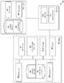
도 3은 일 실시예에 따른, 와이어링 하니스(310)를 갖는 날개(300)의 단면도를 나타낸다. 날개(300)는 비행체(130 또는 230)와 같은 비행체의 날개의 형태를 취하거나 그와 유사할 수 있다.3 illustrates a cross-sectional view of a
도 3에 도시된 바와 같이, 날개(300)는 리딩 에지(322), 상단부(323), 트레일링 에지(324), 하단부(325), 내부 스킨(326), 외부 스킨(327) 및 복수의 스파(328)를 포함할 수 있다. 포켓(329)이 날개 안에 하단부(325)에 또는 그 근처에 파일 수 있다.3, the
리딩 에지(322)는 바람과 처음 접촉하는 날개(300)의 부분이다. 바람은 날개(300)의 표면을 따라 이동하여, 트레일링 에지(324)에서 떠난다.Leading
외부 스킨(327)은 날개(300)의 외면을 형성하도록 날개(300)를 커버할 수 있는 재료의 층이다. 도 3에 도시된 바와 같이, 외부 스킨(327)은 포켓(329) 위에도 형성되어, 날개(300) 상에 외부 스킨(327)의 연속 층을 제공한다. 일부 실시예들에서, 외부 스킨(327)은 섬유 유리, 탄소 섬유 및/또는 수지와 같은 합성물을 포함할 수 있다. 그러한 재료는 스트레스를 잘 처리하지 못하는 날개(300)의 코어에 스트레스를 주지 않고서 내부 스킨(326)의 직접 압축을 가능하게 한다. 날개의 외면을 형성함으로써, 외부 스킨(327)은 일반적으로 환경에 노출될 때 날개(300)의 무결성을 유지하는, 예로서 부식 등에 저항하는 재료로 형성된다.The
내부 스킨(326)은 외부 스킨(327)에 인접하는 날개의 내부 안에 형성되는 재료의 층을 포함할 수 있다. 도 3의 단면도에 도시된 바와 같이, 일 실시예에서, 내부 스킨(326)은 포켓(329)의 위치에서 날개(300)의 내부 주위에 연장하여, 날개(300) 주위의 외부 스킨(327) 아래에서 내부 스킨(326)의 연속층을 제공할 수 있다. 따라서, 내부 스킨(326)은 포켓에서 외부 스킨(327)의 일부에 인접하게 그리고 그 주위에 형성될 수 있다.The
이 실시예에서, 내부 스킨(326)은 포켓(329) 위에 있지 않은 내부 스킨(326)의 다른 부분들로부터 포켓(329)의 위치에서 오프셋되며, 따라서 내부 스킨(326)의 일부는 날개의 코어의 일부가 제거된 포켓(329)의 세그먼트에 형성된다. 내부 스킨(326)은 스킨의 2개의 층 내에서 부하를 줄이기 위해 오프셋의 포인트들에서 오버랩들(321)로 보강될 수 있다. 오프셋의 포인트들은 포켓(329)의 에지들(332)을 포함할 수 있다. 내부 스킨(326)의 연속층을 제공하는 것은 포켓을 포함하는 세그먼트의 비틀림 저항 및 선형 강도를 보전한다. 일부 실시예들에서, 내부 스킨(326)은 EPS(expanded polystyrene) 또는 EPP(expanded polypropylene)와 같은 거품을 포함할 수 있다. 내부 스킨을 위한 다른 재료들도 상상될 수 있다.In this embodiment, the
스파들(328)은 날개(300)에 대한 구조적 지지를 제공하여 날개의 무게를 지탱한다. 스파들(328)은 단단한 재료로 형성될 수 있다. 일부 실시예들에서, 스파들(328)은 거품 코어를 포함할 수 있다. "L" 또는 "T" 형상의 스파 캡들(331)이 각각의 스파(328)의 상부 및 하부에 웰딩 또는 리벳팅되어, 부하 인가에 따른 비틀림을 방지할 수 있다.
포켓(329)은 날개의 하단부(325)에서 또는 그 근처에서 날개(300)의 외부로부터 안쪽으로 오프셋된 공간을 포함한다. 코어의 적어도 일부를 제거하여 포켓(329)을 형성할 수 있다. 포켓(329)은 와이어링 하니스를 수용하도록 크기가 조절되고 성형되며, 이는 아래에서 더 상세히 설명된다. 일부 실시예들에서, 포켓(329)은 날개(300) 내에 리세싱된 채널을 포함하는 것으로 설명될 수 있다. 포켓(329)은 와이어링 하니스(310)의 대응하는 스프링(313)을 유지하기 위해 그의 에지들(332)에 립(lip)(333)을 포함할 수 있다. 포켓(329)은 날개(300)를 제조하기 위한 몰딩 프로세스 동안 형성될 수 있다. 일부 실시예들에서, 포켓(329)은 대체로 사다리 형상 또는 직사각 형상을 포함할 수 있다. 포켓에 대한 다른 형상들도 상상될 수 있으며; 포켓의 형상은 와이어링 하니스(310)의 형상에 대응하고 그를 수용하도록 설계될 수 있다.The
포켓(329)이 날개(300)의 외부의 임의의 위치에 형성될 수 있지만, 날개(300)의 하단부(325)에 또는 그 근처에 포켓(329)을 형성하는 것이 유리할 수 있는데, 이는 하단부(325)가 내부 및 외부 스킨들(326, 327) 상의 낮은 스트레스의 포인트이기 때문이다. 날개 표면에서의 스트레스 집중도는 일반적으로 하단부(325)에서 부하들의 조사를 통해 가장 낮다. 하단부(325)는 플랩형 휨(flapwise bending)에 관한 중립축은 물론 코드형 휨(chordwise bending)에 관한 중립축에 가까우므로 날개(300) 상의 다른 위치들에 비해 낮은 스트레스의 포인트이다. 이와 달리, 상단부(323)은 일반적으로 리프트가 발생하는 곳이며, 따라서 상단부(323)는 양축(예로서, Z축 및 Y축)을 따라 휨을 겪는다.It may be advantageous to form
커버(340)는 외부 스킨(327)에 고정될 수 있다. 닫힌 위치에서, 커버(340)는 포켓(329)에 걸치거나 가로질러 포켓을 커버하고, 따라서 포켓(329) 안의 내용물(예로서, 와이어링 하니스(310))을 보호할 수 있다. 일부 실시예들에서, 커버(340)는 날개(300)의 적어도 일부 위에 본딩되는 해치 커버이며, 이는 포켓(329) 내의 와이어링 하니스(310)를 커버하기 위해 포켓(329)을 가로질러 닫을 수 있다. 그러한 커버는 예로서 수분이 와이어링 하니스(310)에 도달하는 것을 방지하는 데 도움이 될 수 있다. 그러나, 일부 실시예들에서는 커버가 존재하지 않을 수 있다. 예로서, 와이어링 하니스(310)가 수분 흡수에 둔감한 경우, 커버가 환경 내의 수분으로부터 와이어링 하니스를 보호할 필요가 없을 수 있다.The
와이어링 하니스(310)는 전술한 바와 같이 포켓(329) 안에 맞춰지도록 크기가 조절되고 성형될 수 있으며, 포켓(329)을 라이닝하는 외부 스킨(327)의 일부에 고정될 수 있다. 일부 실시예들에서, 와이어링 하니스(310)는 외부 스킨(327)에 제거 가능하게 부착될 수 있다. 와이어링 하니스(310)는 곡선 형상을 포함하는 하나 이상의 스프링(313)을 포함할 수 있다. 스프링들(313)은 와이어링 하니스(310)의 일측에 존재할 수 있으며, 와이어링 하니스(310)를 포켓(329) 내의 적소에 유지하기 위해 포켓(329)의 립(333)의 상부에 놓이도록 압축될 수 있다. 일부 실시예들에서, 와이어링 하니스(310)는 전력 도체들(312) 및/또는 섬유 및 저전압 접속들(314)과 같은 와이어링을 포함할 수 있다. 와이어링 하니스는 아래에서 더 상세히 설명되는 바와 같이 파일론들에 대한 부착을 위해 커넥터들 및 플러그들도 포함할 수 있다.The
도 3에 도시된 바와 같은 와이어링 하니스(310)는 단일 피스(piece)를 포함한다. 그러나, 일부 실시예들에서, 와이어링 하니스(310)는 2개의 피스를 포함할 수 있다(예를 들어, 하나의 피스는 고전압 접속을 위한 것일 수 있고, 제2 피스는 LV 및 통신을 위한 것일 수 있다). 와이어링 하니스가 2개의 피스를 포함하는 실시예에서, 스프링들(313)과 같은 스프링을 포함하는 커버가 2개의 피스의 상부에 스냅핑하거나 맞춰질 수 있다. 그러한 커버는 몰딩된 커버를 포함할 수 있다. 다른 실시예들에서, 커버 대신, 와이어링 하니스 피스들을 캡슐화하고 사용하는 몰딩된 커버와 다른 테이프(예로서, 스트레치 형성 테이프 또는 플랫 테이프) 또는 쉬라우드(shroud)가 사용될 수 있다.The
일부 실시예들에서, 와이어링 하니스(310)는 인젝션 몰딩 프로세스를 이용하여 고무로 제조될 수 있다. 그러한 인젝션 몰딩 프로세스 동안, 와이어링 및 다른 접속들이 와이어링 하니스(310) 내에 몰딩되고, 따라서 임의의 플라잉 리드들이 하니스 상에 형성되는 것을 방지할 수 있다. 일부 실시예들에서, 와이어링 하니스(310)는 날개(300)의 통합 부분이고 그로부터 제거될 수 없도록 날개(300)와 함께 공동 몰딩될 수 있다. 다른 실시예들에서, 와이어링 하니스(310)는 날개(300)와 별개로 형성될 수 있으며, 따라서 와이어링 하니스(310)는 날개(300)로부터 후속적으로 제거될 수 있다. 와이어링 하니스(310)의 제거 가능성은 현재 부착된 와이어링 하니스가 와이어들 또는 접속들 중 하나 이상에서 피로의 징후를 보일 경우에 다른 와이어링 하니스로의 교체를 제공할 수 있다. 날개로부터 결함 있는 와이어링 하니스를 교체하는 것은 날개 전체를 교체하는 것보다 아마도 싸다.In some embodiments, the
다른 실시예들에서, 와이어링 하니스는 압출 프로세스를 이용하여 제조될 수 있으며, 이 경우에 접속들이 와이어링 하니스 상에 스플라이싱(splicing)될 수 있다.In other embodiments, the wiring harness may be fabricated using an extrusion process, in which case the connections may be spliced onto the wiring harness.
전술한 바와 같이, AWT들은 와이어링 요구들을 가질 뿐만 아니라, 고피로 환경에서 동작한다. 통상적으로, 와이어링이 통과할 구멍들이 날개 내의 층들을 통해 형성된다. 그러한 구멍들은 수분을 모으고 유지하는 것을 가능하게 한다. 날개가 터빈 블레이드와 같이 동작하는 고열 환경에서, 그러한 구멍들로부터의 수분 모음은 날개의 합성 재료를 약화시키며, 이는 구멍을 둘러싸는 영역에서 피로를 유발할 수 있다. 그러한 피로는 날개의 무결성 및 수명을 저하시킬 수 있다. 도 3의 날개(300) 및 와이어링 하니스(310)는 날개(300)와 관련된 컴포넌트들에 급전하는 데 충분한 와이어링 및 접속들을 제공하면서, 시종 외부 스킨(327)을 연속적이고 구멍 없이 유지한다.As described above, AWTs have wiring requirements as well as operate in a high fatigue environment. Typically, holes through which the wiring will pass are formed through the layers in the wing. Such holes make it possible to collect and retain moisture. In a high temperature environment where the wings act like a turbine blade, the collection of moisture from such holes weakens the composite material of the wings, which can cause fatigue in the area surrounding the holes. Such fatigue can reduce the integrity and life of the wing. The
도 4a는 일 실시예에 따른, 도 3의 와이어링 하니스(310)의 상세 단면도를 나타낸다. 도 4a에 도시된 바와 같이, 와이어링 하니스(310)는 고무 보드(311) 및 와이어링을 포함할 수 있다. 와이어링은 일 실시예에서 와이어 절연(313)에 의해 둘러싸인 하나 이상의 전력 도체(312), 및 와이어 절연(315)에 의해 또한 둘러싸일 수 있는 하나 이상의 광섬유 라인(314)을 포함할 수 있다. 본 명세서에서 사용되는 바와 같은 광섬유 라인이라는 용어는 광섬유 라인만을 설명하는 데 사용될 수 있거나, (예로서, 와이어 절연(315)과 같은) 절연 또는 다수의 다른 보호층에 의해 둘러싸인 광섬유 라인을 포함할 수 있다. 광섬유 라인들은 섬유의 2개의 단부 사이에서 광을 전송하기 위한 도파관으로서 기능하는 유리 또는 플라스틱 섬유들의 가닥들을 포함할 수 있다. 와이어 절연들(313, 315)은 두께가 다를 수 있으며, 일부 실시예들에서는 더 얇은 층이 적용될 수 있는데, 이는 전력 도체들(312) 및 광섬유 라인들(314)을 내장하는 와이어링 하니스가 소정의 보호도 제공하기 때문이다. 4개의 도체(312) 및 4개의 광섬유 라인(314)이 도 4a에 도시되지만, 더 많거나 적은 각각이 와이어링 하니스(310)의 일부로서 형성될 수 있다. 도 4a에 도시된 실시예에서, 모든 와이어링은 1개 또는 2개의 케이블을 통해 연장한다. 케이블들은 플랫 리본 케이블을 포함할 수 있다. 2개의 케이블이 와이어링 하니스(310)를 위해 사용되는 경우, 일 실시예에서 하나의 케이블은 HV 케이블을 포함할 수 있고, 다른 케이블은 LV 케이블을 포함할 수 있다. 와이어링은 스트레치를 허용하기 위해 가닥 구리 또는 알루미늄 재료와 같은 얕은 피치 각도의 고신장 재료로 형성될 수 있거나, 비직선 경로, 예로서 미리 휘어진 지그재그 형태로 와이어링 재킷 내에 삽입될 수 있다. 날개가 펼쳐짐에 따라 와이어링 또한 펼쳐질 수 있다.FIG. 4A shows a detailed cross-sectional view of the
도 4b는 일 실시예에 따른, 도 3의 와이어링 하니스(310) 내에 존재할 수 있는 접합(410)을 나타내다. 와이어링(420)은 하니스(310)를 통해 연장하는 것으로 도시된다. 와이어링(420)은 전력 도체들(312) 및 광섬유 라인들(314)과 같은 형태를 취하거나 이들과 유사할 수 있는 전력 도체들 및 광섬유 라인들을 포함할 수 있다. 와이어링은 커넥터(430) 내로 공급될 수 있다. 커넥터(430)는 일부 실시예들에서 솔더 또는 크림프로 제조될 수 있다. 도 4b에 도시된 바와 같이, 커넥터(430)는 커넥터(430)에 국지적인 스트레인 완화를 제공하기 위해 와이어링의 직각 세그먼트들(422)을 이용하여 제조될 수 있다.Figure 4B illustrates a
그러한 접합(410)은 접합(410)의 격리를 유지하기 위해 와이어링 하니스(310) 내에 내장될 수 있다. 이롭게도, 그러한 접합들(410)은 예로서 날개(300)의 중심과 같은 특정 위치에 모든 또는 상당한 수의 커넥터가 형성됨으로 인해 와이어링 런들의 반복을 방지한다.Such a
도 4c-e는 일 실시예에 따른, 도 3의 와이어링 하니스(310)와 같은 와이어링 하니스 내에 존재할 수 있는 플러그 또는 커넥터 구성(450)의 도면들을 나타낸다. 도 4c에 도시된 평면도에서, 커넥터(452)가 존재하고, 절연층(456)에 의해 둘러싸인다. 커넥터(452)는 일부 실시예들에서 HV 밴드 플러그를 포함할 수 있고, 파일론을 수용하도록 구성될 수 있다. 절연(459) 내에 커버된 (도 4d-e에 와이어(458)로 도시된) 와이어가 커넥터(452) 내로 공급된다.4c-e illustrate views of a plug or
접합(450)의 측면도가 도 4d에 도시된다. 도 4d에 도시된 바와 같이, 절연(459)은 와이어의 세그먼트 위에서 와이어(458)로부터 벗겨질 수 있고, 따라서 커넥터(452) 내로 공급되는 와이어(458)의 세그먼트가 노출될 수 있다.A side view of the
도 4e는 커넥터(452), 절연층(456) 및 와이어(458)의 배치를 나타내는, 도 4c의 단면 A-A에서의 접합(450)의 정면도를 나타낸다. 와이어(458)의 일부 주위의 절연(459)도 도시된다.4E shows a front view of the
커넥터(452)는 와이어링 하니스(310)가 인젝션 몰딩되는 실시예에서 와이어링 하니스(310)의 몰딩 전에 와이어(458) 상에 솔더링 또는 크림핑될 수 있다. 몰딩 프로세스 동안, 커넥터(452)의 적어도 일부가 캡 또는 필러로 커버되어, 커넥터(452) 전체의 오버몰딩을 방지할 수 있다. 커넥터는 와이어링 하니스(310)의 몰딩 재료와의 양호한 본드를 제공하도록 사전 처리될 수 있다. 따라서, 커넥터는 와이어링 하니스 내에 형성될 수 있고, 이는 유리할 수 있다. 커넥터(452)의 대부분을 와이어링 하니스(310) 내로 리세싱함으로써, 커넥터(452)는 더 강건하고 단단하며, 이는 예로서 부착 프로세스 동안의 커넥터의 기계적 조작으로 인해 와이어링 하니스를 교체할 필요성을 줄일 수 있다.The
D. 전력을 제공하기 위한 시스템들D. Systems to Provide Power
도 5는 컴포넌트에 전력을 제공하기 위한 예시적인 시스템(500)을 나타낸다. 시스템(500)은 적어도 하나의 플러그(530)를 포함하는 와이어링 하니스(520)를 갖는 날개(510)를 포함하며, 플러그(530)는 파일론(540)을 통해 컴포넌트(550)에 부착된다.FIG. 5 shows an
날개(510)는 비행체(130 또는 230)와 같은 비행체의 일부일 수 있다. 날개(510)는 비행체의 주 날개일 수 있으며, 도 3의 날개(300)의 형태를 취하거나 그와 형태가 유사할 수 있고, 와이어링 하니스(520)의 삽입을 위한 포켓(512)을 포함할 수 있다.The
도 5의 실시예에서, 플러그 또는 커넥터(530)는 고전압 접속들 및 응용들을 위해 구성된다. 그러나, 동일 또는 유사한 커넥터 구성이 더 낮은 전압을 요구하는 광섬유 또는 다른 접속들을 위해 사용될 수 있다. 커넥터(530)는 도 4c-e의 실시예에서 설명된 바와 같이 와이어링 하니스(520) 내에 형성될 수 있고, 따라서 그와 통합될 수 있다.In the embodiment of FIG. 5, the plug or
파일론(540)은 예로서 AWT 상에 외부적으로 컴포넌트(550)와 같은 장비를 탑재하는 데 사용되는 다수의 구조 중 임의의 구조를 포함할 수 있다. 파일론(540)은 커넥터(530)와 결합하도록 구성된다. 파일론(540)은 일부 실시예들에서 주 날개의 트레일링 에지 플랩들을 유지하는 파울러 파일론을 포함할 수 있다. 다른 실시예들에서, 파일론(540)은 모터들 및 프로펠러들을 부착할 수 있는 모터 파일론을 포함할 수 있다. 파일론(540)은 날개(510) 상에 볼팅될 수 있다. 와이어링 하니스(520)는 파일론(540)에 대한 전력 및 통신을 접속할 수 있다.The
컴포넌트(550)는 날개에 부착되고 그에 의해 급전되는 다수의 컴포넌트 중 임의의 컴포넌트를 포함할 수 있으며, 전술한 바와 같이, 파일론(540)에 부착될 수 있다. 컴포넌트는 플랜지를 포함할 수 있고, 플랜지 상에 또는 그 주위에 날개(510)에 부착되는 볼트들을 갖는다.The
도 5의 시스템은 몰딩 프로세스 동안 커넥터(530)를 와이어링 하니스(520) 내에 내장하는 것의 다른 장점을 나타내며: 그렇게 함으로써, 커넥터(530)는 와이어링 하니스(520) 상의 위치에 정밀하게 배치될 수 있다. 커넥터(530)를 와이어링 하니스(520) 내에 정밀하게 몰딩하기 위한 능력은 2-단계 설치 프로세스 없이 기계적 접속이 행해질 때 전기적 접속이 행해지는 것을 가능하게 한다. 일부 실시예들에서, 전기 커넥터가 아니라 기계적 정렬을 이용하여 부착을 위한 기계 볼트 구멍들을 배치할 수 있다. 다른 실시예들에서는, 전기 접속이 기계 볼트 구멍들을 배치하는 데 사용될 수 있다. (커넥터(530)에 부착되는) 파일론(540)은 날개(510) 위에 배치될 수 있으며, 이 경우에 볼트들은 또한 날개(510) 안으로 들어갈 것이다. 동시적인 기계 및 전기 접속들이 이루어질 수 있으므로, 기계 또는 전기 접속들이 행해지지만 둘 다 행해지지는 않는 사례들과 같은 유지보수 실패 사례들이 방지될 수 있다.The system of Figure 5 represents another advantage of embedding the
E. 와이어링 하니스E. Wiring Harness를To 제조하기 위한 방법 Method for manufacturing
도 6은 일 실시예에 따른 방법(600)을 나타내는 흐름도이다. 방법(600)은 와이어링 하니스를 제조하는 데 사용될 수 있다.6 is a flow diagram illustrating a
블록 602에 도시된 바와 같이, 방법(600)은 하나 이상의 와이어의 세그먼트로부터 절연층을 벗기는 단계를 포함한다. 와이어들은 전력 도체들(312) 및 광섬유 라인들(314)과 같은 형태를 취하거나 이들과 유사할 수 있는 전력 도체들 및 광섬유 라인들을 포함할 수 있다.As shown in
블록 604에서, 방법(600)은 하나 이상의 와이어의 벗겨진 세그먼트를 커넥터에 부착하는 단계를 포함한다. 커넥터는 커넥터(452)의 형태를 취하거나 그와 형태가 유사할 수 있다. 벗겨진 세그먼트의 부착은 도 4c-e를 참조하여 설명되고 도시된 바와 같이 수행될 수 있다.At
블록 606에서, 방법(600)은 커넥터의 일부 위에 보호층을 형성하는 단계를 포함한다. 보호층은 캡 또는 필러와 같은 커버를 포함할 수 있다. 커넥터는 와이어링 하니스의 몰딩 재료와의 양호한 본드를 제공하도록 사전 처리될 수 있다.At
블록 608에서, 방법(600)은 하나 이상의 와이어 및 커넥터 주위에 하니스 보디를 몰딩하는 단계를 포함한다. 보호층은 몰딩 프로세스 동안 커넥터 전체의 오버몰딩을 방지할 수 있다.At
방법(600)은 블록 610에서 보호층을 제거하여 커넥터의 일부를 노출시키는 단계를 더 포함한다. 노출된 커넥터는 파일론 또는 컴포넌트를 수용할 수 있다.The
III.III.결론conclusion
도면에 도시되는 특정 배열들은 제한하기 위한 것으로 보지 말아야 한다. 다른 실시예들이 주어진 도면에 도시되는 각각의 요소의 대부분을 포함할 수 있음을 이해해야 한다. 더욱이, 예시된 요소들 중 일부는 결합되거나 생략될 수 있다. 또 다른 일 실시예는 도면에 예시되지 않는 요소들을 포함할 수 있다.The particular arrangements shown in the drawings should not be construed as limiting. It is to be understood that other embodiments may include most of the elements illustrated in the figures. Moreover, some of the illustrated elements may be combined or omitted. Still another embodiment may include elements not illustrated in the figures.
게다가, 본 명세서에 다양한 양태들 및 실시예들이 개시되었지만, 본 기술의 통상의 기술자에게는 다른 양태들 및 실시예들이 자명할 것이다. 본 명세서에 개시된 다양한 양태들 및 실시예들은 예시를 목적으로 한 것이고 제한적인 것으로 의도된 것이 아니며, 그 진정한 범주 및 사상은 하기 청구범위에 의해 나타나 있다. 본 명세서에 제시된 발명 대상의 사상 또는 범주로부터 벗어나지 않는 한, 다른 실시예들이 활용될 수도 있고 다른 변경들이 이루어질 수도 있다. 본 명세서에 일반적으로 설명되고 도면들에 예시된 바와 같은 본 개시 내용의 양태들은 매우 다양한 상이한 구성들로 배열되고, 치환되고, 조합되고, 분리되고, 설계될 수 있으며, 그 모두가 본 명세서에서 고려됨을 쉽게 이해할 것이다.In addition, while various aspects and embodiments have been disclosed herein, other aspects and embodiments will be apparent to those of ordinary skill in the art. The various aspects and embodiments disclosed herein are for the purpose of illustration and not of limitation, the true scope and spirit of which is set forth in the following claims. Other embodiments may be utilized and other modifications may be made without departing from the spirit or scope of the inventive subject matter presented herein. Aspects of the present disclosure, as generally described herein and illustrated in the drawings, may be arranged, substituted, combined, separated, and designed in a wide variety of different configurations, all of which are contemplated herein Will be easy to understand.
Claims (19)
Translated fromKorean보디;
상기 보디 내의 케이블 내에 내장된 하나 이상의 와이어; 및
상기 보디 내에 부분적으로 내장되고, 상기 하나 이상의 와이어와 통신하는 하나 이상의 커넥터
를 포함하는 와이어링 하니스.As a wiring harness that can be attached to a wing of a flight vehicle,
Body;
One or more wires embedded within the cable within the body; And
At least one connector that is partially embedded in the body and is in communication with the at least one wire
And a wire harness.
상기 하나 이상의 와이어는 절연층에 의해 각자 둘러싸이는 도체들 및 광섬유 라인들을 포함하는 와이어링 하니스.The method according to claim 1,
Wherein the at least one wire comprises conductors and fiber optic lines that are each surrounded by an insulating layer.
상기 하나 이상의 와이어는 몰딩된 케이블 내에 더 삽입되어, 상기 하나 이상의 와이어와 접지 사이에 2개 이상의 절연층이 제공되는 와이어링 하니스.3. The method of claim 2,
Wherein the at least one wire is further inserted into the molded cable such that at least two insulating layers are provided between the at least one wire and the ground.
상기 보디는 상기 하나 이상의 와이어 및 상기 하나 이상의 커넥터 중 적어도 일부 주위에 몰딩된 고무를 포함하고, 상기 하나 이상의 커넥터는 파일론(pylon)을 수용하도록 구성되는 와이어링 하니스.The method according to claim 1,
Wherein the body includes rubber molded around the at least one wire and at least a portion of the at least one connector, the at least one connector configured to receive a pylon.
상기 내장된 하나 이상의 와이어는 비직선 경로를 따르며, 신장(elongation)이 가능한 재료를 포함하는 와이어링 하니스.The method according to claim 1,
Wherein the embedded one or more wires follow a non-linear path and include a material capable of elongation.
상기 하나 이상의 와이어는 90도의 각도로 휘고, 접합을 형성하도록 크림핑(crimping)되며, 상기 접합은 상기 보디 내에 내장되는 와이어링 하니스.The method according to claim 1,
Wherein the at least one wire is crimped at an angle of 90 degrees to form a bond, the bond being embedded within the body.
상기 하나 이상의 와이어는 절연층을 더 포함하는 와이어링 하니스.The method according to claim 1,
Wherein the at least one wire further comprises an insulating layer.
상기 하나 이상의 커넥터 중 하나는 상기 하나 이상의 와이어 중 하나에 상기 절연층이 벗겨진 상기 와이어의 세그먼트에서 부착되는 와이어링 하니스.8. The method of claim 7,
Wherein one of the one or more connectors is attached to one of the one or more wires in a segment of the wire stripped of the insulating layer.
날개를 포함하는 비행체 - 상기 날개는 포켓을 포함함 -; 및
상기 포켓 내에 제공된 하니스
를 포함하고,
상기 하니스는
보디;
상기 보디 내의 케이블 내에 내장된 하나 이상의 와이어; 및
상기 보디 내에 부분적으로 내장된 하나 이상의 커넥터
를 포함하는 시스템.As a system,
A flying body comprising a wing, said wing including a pocket; And
The harness
Lt; / RTI >
The harness
Body;
One or more wires embedded within the cable within the body; And
At least one connector partially embedded in the body
/ RTI >
상기 포켓은 상기 날개의 리세싱된 부분(recessed section)으로서 형성되는 시스템.10. The method of claim 9,
Wherein the pocket is formed as a recessed section of the vane.
합성물로 형성된 외부층 - 상기 외부층은 포켓을 포함하는, 상기 날개의 외면을 형성함 -;
상기 외부층에 인접하게 상기 날개의 내부 안에 형성된 내부층; 및
상기 내부층에 인접하게 상기 내부 안에 형성된 내부 코어
를 더 포함하고,
상기 내부층은 상기 포켓에서 상기 외부층의 일부 주위에 형성되는 시스템.11. The method of claim 10,
An outer layer formed of a composite, said outer layer comprising a pocket, said outer layer defining an outer surface of said wing;
An inner layer formed in the interior of the vane adjacent the outer layer; And
An inner core formed in the interior adjacent the inner layer,
Further comprising:
Wherein the inner layer is formed around a portion of the outer layer in the pocket.
상기 내부 코어의 적어도 일부는 상기 포켓을 형성하도록 제거되며,
상기 시스템은
상기 내부 코어의 상기 일부가 제거된 상기 포켓의 세그먼트에 형성된 상기 내부층의 일부; 및
상기 내부층이 상기 포켓에 의해 중단되지 않도록 상기 날개 주위의 연속층을 형성하는, 상기 포켓의 에지들 주위의 상기 내부층의 오버랩핑 부분
을 더 포함하는 시스템.12. The method of claim 11,
Wherein at least a portion of the inner core is removed to form the pocket,
The system
A portion of the inner layer formed in a segment of the pocket from which the portion of the inner core is removed; And
Forming a continuous layer around the vane such that the inner layer is not interrupted by the pocket, the overlapping portion of the inner layer about the edges of the pocket
≪ / RTI >
상기 포켓 내에 제공된 상기 하니스는 상기 외부층에 배치되는 시스템.12. The method of claim 11,
Wherein the harness provided in the pocket is disposed in the outer layer.
상기 포켓의 에지들은 립(lip)을 더 포함하고, 상기 하니스는 상기 하니스가 상기 포켓 내에 있을 때 상기 립의 상부에 압축된 형태로 배치되도록 스프링을 더 포함하는 시스템.10. The method of claim 9,
Wherein the edges of the pocket further comprise a lip and wherein the harness further comprises a spring to be disposed in a compressed form on top of the lip when the harness is in the pocket.
상기 포켓은 상기 날개들의 다른 부분들에 비해 스트레스 집중도가 더 낮은, 상기 날개의 외부층의 저신장 포인트(low elongation point)에 형성되는 시스템.10. The method of claim 9,
Wherein the pocket is formed at a low elongation point of the outer layer of the wing, the stress concentration of which is lower than that of the other portions of the wings.
상기 날개는 닫힌 위치에서 상기 포켓에 걸치는 커버를 더 포함하는 시스템.10. The method of claim 9,
Wherein the wings further include a cover that spans the pocket in a closed position.
하나 이상의 와이어의 세그먼트로부터 절연층을 벗기는 단계;
상기 하나 이상의 와이어의 상기 벗겨진 세그먼트를 커넥터에 부착하는 단계;
상기 커넥터의 일부 위에 보호층을 형성하는 단계;
상기 하나 이상의 와이어 및 상기 커넥터 주위에 하니스 보디를 몰딩하는 단계; 및
상기 보호층을 제거하여 상기 커넥터의 상기 일부를 노출시키는 단계
를 포함하는 방법.A method for manufacturing a wiring harness,
Stripping the insulating layer from a segment of the at least one wire;
Attaching the stripped segments of the at least one wire to a connector;
Forming a protective layer over a portion of the connector;
Molding the harness body around the at least one wire and the connector; And
Removing the protective layer to expose the portion of the connector
≪ / RTI >
상기 벗겨진 세그먼트를 상기 커넥터에 부착하는 단계는 상기 벗겨진 세그먼트를 상기 커넥터에 솔더링하는 단계를 포함하는 방법.18. The method of claim 17,
Wherein attaching the stripped segment to the connector comprises soldering the stripped segment to the connector.
상기 벗겨진 세그먼트를 상기 커넥터에 부착하는 단계는 상기 벗겨진 세그먼트를 상기 커넥터에 크림핑하는 단계를 포함하는 방법.18. The method of claim 17,
Wherein attaching the stripped segment to the connector comprises crimping the stripped segment to the connector.
Applications Claiming Priority (3)
| Application Number | Priority Date | Filing Date | Title |
|---|---|---|---|
| US14/143,543US9205920B2 (en) | 2013-12-30 | 2013-12-30 | Wiring harness for an aerial vehicle |
| US14/143,543 | 2013-12-30 | ||
| PCT/US2014/071902WO2015103000A1 (en) | 2013-12-30 | 2014-12-22 | Wiring harness for an aerial vehicle |
Publications (2)
| Publication Number | Publication Date |
|---|---|
| KR20160091405A KR20160091405A (en) | 2016-08-02 |
| KR101893665B1true KR101893665B1 (en) | 2018-08-30 |
Family
ID=53480907
Family Applications (1)
| Application Number | Title | Priority Date | Filing Date |
|---|---|---|---|
| KR1020167017188AExpired - Fee RelatedKR101893665B1 (en) | 2013-12-30 | 2014-12-22 | Wiring harness for an aerial vehicle |
Country Status (7)
| Country | Link |
|---|---|
| US (2) | US9205920B2 (en) |
| EP (1) | EP3090173A4 (en) |
| JP (1) | JP6215491B2 (en) |
| KR (1) | KR101893665B1 (en) |
| CN (1) | CN105814308B (en) |
| AU (1) | AU2014374074B2 (en) |
| WO (1) | WO2015103000A1 (en) |
Families Citing this family (12)
| Publication number | Priority date | Publication date | Assignee | Title |
|---|---|---|---|---|
| ITTO20120299A1 (en)* | 2012-04-05 | 2013-10-06 | Oto Melara Spa | DEVICE AND METHOD FOR THE AUTOMATIC CONTROL OF A WINCH AND VEHICLE DEVICE TO WHICH THIS DEVICE IS APPLIED. |
| US9879655B1 (en)* | 2014-06-30 | 2018-01-30 | X Development Llc | Attachment apparatus for an aerial vehicle |
| US10643290B2 (en)* | 2015-10-23 | 2020-05-05 | Bell Helicopter Textron Inc. | Identification tags for tracking manufacturing of aircraft parts |
| CN106785800B (en)* | 2017-02-16 | 2023-03-21 | 天津东驰机电设备有限公司 | Automobile wire harness guiding and inserting device |
| WO2018206064A1 (en)* | 2017-05-11 | 2018-11-15 | Vestas Wind Systems A/S | A wind turbine and an airborne wind energy system sharing yaw system |
| CN109533363A (en)* | 2018-11-09 | 2019-03-29 | 中国直升机设计研究所 | A kind of unmanned helicopter electrical harness interacted system |
| US11211184B2 (en) | 2019-01-23 | 2021-12-28 | Pratt & Whitney Canada Corp. | System of harness and engine case for aircraft engine |
| CN111942188B (en)* | 2020-08-11 | 2022-04-12 | 北京京东乾石科技有限公司 | Unmanned aerial vehicle aerial charging system, charging method, device, equipment and medium |
| US12338008B2 (en)* | 2021-09-17 | 2025-06-24 | Singapore University Of Technology And Design | Monocopter |
| CN114019631A (en)* | 2021-10-22 | 2022-02-08 | 中国空空导弹研究院 | External communication hybrid cable of small airborne vehicle |
| CN113886402B (en)* | 2021-12-08 | 2022-03-15 | 成都飞机工业(集团)有限责任公司 | Aviation wire harness information integration method based on branches and readable storage medium |
| FR3140446B1 (en)* | 2022-09-30 | 2024-10-25 | Safran Helicopter Engines | Device for measuring the rotation speed of an aircraft propeller |
Citations (3)
| Publication number | Priority date | Publication date | Assignee | Title |
|---|---|---|---|---|
| JP2011243318A (en) | 2010-05-14 | 2011-12-01 | Sumitomo Electric Ind Ltd | Optoelectronic composite cable |
| US20120103685A1 (en) | 2010-10-29 | 2012-05-03 | Airbus Operations Limited | Aircraft cable routing harness |
| US20120325553A1 (en) | 2010-03-15 | 2012-12-27 | Yazaki Corporation | Method for manufacturing circuit body and wire harness |
Family Cites Families (19)
| Publication number | Priority date | Publication date | Assignee | Title |
|---|---|---|---|---|
| US3182280A (en)* | 1963-04-19 | 1965-05-04 | Francis X Daut | Protection of electrical connector contact pins |
| JPH0224295A (en)* | 1988-07-09 | 1990-01-26 | Kiyoshi Tada | Air flying body connected to ground by wire |
| US5308264A (en) | 1993-04-15 | 1994-05-03 | United Technologies Corporation | Modular backshell interface system |
| DK173460B2 (en) | 1998-09-09 | 2004-08-30 | Lm Glasfiber As | Windmill wing with lightning conductor |
| DE10259680B4 (en)* | 2002-12-18 | 2005-08-25 | Aloys Wobben | Rotor blade of a wind turbine |
| US7234667B1 (en)* | 2003-12-11 | 2007-06-26 | Talmage Jr Robert N | Modular aerospace plane |
| DK178207B1 (en) | 2004-01-23 | 2015-08-17 | Lm Wind Power As | Wing for a wind power plant comprising segmented lightning conductors and method of manufacturing them |
| ES2310958B1 (en) | 2006-09-15 | 2009-11-10 | GAMESA INNOVATION & TECHNOLOGY, S.L. | OPTIMIZED AEROGENERATOR SHOVEL. |
| US7765695B2 (en)* | 2007-05-29 | 2010-08-03 | Channell Commercial Corporation | Method and process for manufacturing a terminal block |
| EP2110552B2 (en) | 2008-04-15 | 2018-12-26 | Siemens Aktiengesellschaft | Wind turbine blade with an integrated lightning conductor and method for manufacturing the same |
| US8256715B2 (en)* | 2008-11-18 | 2012-09-04 | Mavg, Llc | Devices, systems and methods for modular payload integration for unmanned aerial vehicles |
| EP2226497A1 (en) | 2009-03-06 | 2010-09-08 | Lm Glasfiber A/S | Wind turbine blade with a lightning protection system |
| WO2011077970A1 (en) | 2009-12-24 | 2011-06-30 | 三菱重工業株式会社 | Wind wheel blade and wind-driven electricity generation device with same |
| DE102011105228B3 (en) | 2011-06-10 | 2012-09-20 | Nordex Energy Gmbh | Wind turbine component with an electrical cable embedded in a laminate |
| US8834117B2 (en) | 2011-09-09 | 2014-09-16 | General Electric Company | Integrated lightning receptor system and trailing edge noise reducer for a wind turbine rotor blade |
| JP5884134B2 (en)* | 2011-11-25 | 2016-03-15 | 矢崎総業株式会社 | Manufacturing method of wire harness |
| US9478896B2 (en)* | 2011-12-22 | 2016-10-25 | Rolls-Royce Plc | Electrical connectors |
| GB2498006B (en)* | 2011-12-22 | 2014-07-09 | Rolls Royce Plc | Gas turbine engine systems |
| JP5906544B2 (en)* | 2012-04-17 | 2016-04-20 | 矢崎総業株式会社 | Wire harness |
- 2013
- 2013-12-30USUS14/143,543patent/US9205920B2/ennot_activeExpired - Fee Related
- 2014
- 2014-12-22CNCN201480068115.2Apatent/CN105814308B/ennot_activeExpired - Fee Related
- 2014-12-22JPJP2016561593Apatent/JP6215491B2/ennot_activeExpired - Fee Related
- 2014-12-22WOPCT/US2014/071902patent/WO2015103000A1/enactiveApplication Filing
- 2014-12-22KRKR1020167017188Apatent/KR101893665B1/ennot_activeExpired - Fee Related
- 2014-12-22EPEP14875921.0Apatent/EP3090173A4/ennot_activeWithdrawn
- 2014-12-22AUAU2014374074Apatent/AU2014374074B2/ennot_activeCeased
- 2015
- 2015-11-05USUS14/933,765patent/US9828091B2/ennot_activeExpired - Fee Related
Patent Citations (3)
| Publication number | Priority date | Publication date | Assignee | Title |
|---|---|---|---|---|
| US20120325553A1 (en) | 2010-03-15 | 2012-12-27 | Yazaki Corporation | Method for manufacturing circuit body and wire harness |
| JP2011243318A (en) | 2010-05-14 | 2011-12-01 | Sumitomo Electric Ind Ltd | Optoelectronic composite cable |
| US20120103685A1 (en) | 2010-10-29 | 2012-05-03 | Airbus Operations Limited | Aircraft cable routing harness |
Also Published As
| Publication number | Publication date |
|---|---|
| US20150183515A1 (en) | 2015-07-02 |
| JP6215491B2 (en) | 2017-10-18 |
| US9205920B2 (en) | 2015-12-08 |
| US20160052629A1 (en) | 2016-02-25 |
| JP2017504762A (en) | 2017-02-09 |
| EP3090173A4 (en) | 2017-08-02 |
| CN105814308A (en) | 2016-07-27 |
| AU2014374074A1 (en) | 2016-05-19 |
| EP3090173A1 (en) | 2016-11-09 |
| WO2015103000A1 (en) | 2015-07-09 |
| AU2014374074B2 (en) | 2017-09-28 |
| KR20160091405A (en) | 2016-08-02 |
| CN105814308B (en) | 2018-11-13 |
| US9828091B2 (en) | 2017-11-28 |
Similar Documents
| Publication | Publication Date | Title |
|---|---|---|
| KR101893665B1 (en) | Wiring harness for an aerial vehicle | |
| US9884692B2 (en) | Systems and methods for controlling rotation and twist of a tether | |
| US20150180186A1 (en) | Systems and Apparatus for Cable Management | |
| KR101737751B1 (en) | Path based power generation control for an aerial vehicle | |
| KR101680687B1 (en) | Methods and systems for transitioning an aerial vehicle between hover flight and crosswind flight | |
| TWI679344B (en) | Electro-mechanical bridles for energy kites | |
| KR20160043093A (en) | Methods and systems for transitioning an aerial vehicle between crosswind flight and hover flight | |
| US9899127B2 (en) | Tethers for airborne wind turbines | |
| US20160355259A1 (en) | Hardpoint Strain Reliefs | |
| US9947434B2 (en) | Tethers for airborne wind turbines using electrical conductor bundles | |
| US9352930B2 (en) | Methods and systems for winding a tether | |
| US20180094993A1 (en) | Torsion Relieving Power Cable | |
| US10311998B2 (en) | High-elongation tensile cable with undulating transmission cable | |
| US10323353B2 (en) | Faired tether systems with internal support structure in the faired tether | |
| US20190100305A1 (en) | Faired Tether Systems with Tail Span Sections |
Legal Events
| Date | Code | Title | Description |
|---|---|---|---|
| A201 | Request for examination | ||
| P11-X000 | Amendment of application requested | St.27 status event code:A-2-2-P10-P11-nap-X000 | |
| P13-X000 | Application amended | St.27 status event code:A-2-2-P10-P13-nap-X000 | |
| PA0105 | International application | St.27 status event code:A-0-1-A10-A15-nap-PA0105 | |
| PA0201 | Request for examination | St.27 status event code:A-1-2-D10-D11-exm-PA0201 | |
| PG1501 | Laying open of application | St.27 status event code:A-1-1-Q10-Q12-nap-PG1501 | |
| N231 | Notification of change of applicant | ||
| PN2301 | Change of applicant | St.27 status event code:A-3-3-R10-R13-asn-PN2301 St.27 status event code:A-3-3-R10-R11-asn-PN2301 | |
| E902 | Notification of reason for refusal | ||
| PE0902 | Notice of grounds for rejection | St.27 status event code:A-1-2-D10-D21-exm-PE0902 | |
| P11-X000 | Amendment of application requested | St.27 status event code:A-2-2-P10-P11-nap-X000 | |
| P13-X000 | Application amended | St.27 status event code:A-2-2-P10-P13-nap-X000 | |
| E701 | Decision to grant or registration of patent right | ||
| PE0701 | Decision of registration | St.27 status event code:A-1-2-D10-D22-exm-PE0701 | |
| PR0701 | Registration of establishment | St.27 status event code:A-2-4-F10-F11-exm-PR0701 | |
| PR1002 | Payment of registration fee | St.27 status event code:A-2-2-U10-U12-oth-PR1002 Fee payment year number:1 | |
| PG1601 | Publication of registration | St.27 status event code:A-4-4-Q10-Q13-nap-PG1601 | |
| PN2301 | Change of applicant | St.27 status event code:A-5-5-R10-R11-asn-PN2301 | |
| PN2301 | Change of applicant | St.27 status event code:A-5-5-R10-R14-asn-PN2301 | |
| PC1903 | Unpaid annual fee | St.27 status event code:A-4-4-U10-U13-oth-PC1903 Not in force date:20210825 Payment event data comment text:Termination Category : DEFAULT_OF_REGISTRATION_FEE | |
| PC1903 | Unpaid annual fee | St.27 status event code:N-4-6-H10-H13-oth-PC1903 Ip right cessation event data comment text:Termination Category : DEFAULT_OF_REGISTRATION_FEE Not in force date:20210825 | |
| P22-X000 | Classification modified | St.27 status event code:A-4-4-P10-P22-nap-X000 |