KR101893347B1 - Fire door - Google Patents
Fire doorDownload PDFInfo
- Publication number
- KR101893347B1 KR101893347B1KR1020180056890AKR20180056890AKR101893347B1KR 101893347 B1KR101893347 B1KR 101893347B1KR 1020180056890 AKR1020180056890 AKR 1020180056890AKR 20180056890 AKR20180056890 AKR 20180056890AKR 101893347 B1KR101893347 B1KR 101893347B1
- Authority
- KR
- South Korea
- Prior art keywords
- door
- sealing
- differential pressure
- upper frame
- closed
- Prior art date
- Legal status (The legal status is an assumption and is not a legal conclusion. Google has not performed a legal analysis and makes no representation as to the accuracy of the status listed.)
- Active
Links
Images


Classifications
- E—FIXED CONSTRUCTIONS
- E06—DOORS, WINDOWS, SHUTTERS, OR ROLLER BLINDS IN GENERAL; LADDERS
- E06B—FIXED OR MOVABLE CLOSURES FOR OPENINGS IN BUILDINGS, VEHICLES, FENCES OR LIKE ENCLOSURES IN GENERAL, e.g. DOORS, WINDOWS, BLINDS, GATES
- E06B5/00—Doors, windows, or like closures for special purposes; Border constructions therefor
- E06B5/10—Doors, windows, or like closures for special purposes; Border constructions therefor for protection against air-raid or other war-like action; for other protective purposes
- E06B5/16—Fireproof doors or similar closures; Adaptations of fixed constructions therefor
- E06B5/162—Fireproof doors having windows or other openings, e.g. for permitting ventilation or escape
- E—FIXED CONSTRUCTIONS
- E06—DOORS, WINDOWS, SHUTTERS, OR ROLLER BLINDS IN GENERAL; LADDERS
- E06B—FIXED OR MOVABLE CLOSURES FOR OPENINGS IN BUILDINGS, VEHICLES, FENCES OR LIKE ENCLOSURES IN GENERAL, e.g. DOORS, WINDOWS, BLINDS, GATES
- E06B9/00—Screening or protective devices for wall or similar openings, with or without operating or securing mechanisms; Closures of similar construction
- E06B9/52—Devices affording protection against insects, e.g. fly screens; Mesh windows for other purposes
Landscapes
- Engineering & Computer Science (AREA)
- Structural Engineering (AREA)
- Civil Engineering (AREA)
- Life Sciences & Earth Sciences (AREA)
- Insects & Arthropods (AREA)
- Pest Control & Pesticides (AREA)
- Architecture (AREA)
- Special Wing (AREA)
Abstract
Translated fromKoreanDescription
Translated fromKorean본 발명은 방화문에 관한 것으로, 더욱 상세하게는 화재 발생시 제연구역과 비제연구역을 구획하여 화염, 연기, 유독가스가 다른 곳으로 확산되는 것을 방지할 수 있음과 동시에 차압의 해소를 통해 방화문의 개폐가 용이한 방화문에 관한 것이다.More particularly, the present invention relates to a fire door, and more particularly, to a fire door that divides a smoke and a non-fire area to prevent flames, smoke, and toxic gases from spreading to other places, The present invention relates to a fire door which is easy to use.
일반적으로, 고층빌딩, 아파트, 병원 등지에는 현행법상 제연설비가 필수적으로 설치되며, 제연설비는 최초화재 발생시 화재 감지기에 의해 종합 방제실에 화재발생 신호가 전달되면, 급기댐퍼의 송풍이 이루어져 비제연구역과 제연구역과의 압력차이를 자동으로 유지함으로써, 화재의 확산을 방지함과 아울러 비상계단 등의 대피통로를 안정되게 확보하도록 하고 있다.In general, smoke-free facilities are installed in high-rise buildings, apartments, hospitals, etc. In case of fire, when the fire signal is transmitted to the general control room by fire detector in the first fire, air supply damper is blown, By automatically maintaining the pressure difference between the station and the research station, it is possible to prevent the spread of the fire and secure the escape passage such as the emergency stairs.
그리고, 상기 제연구역과 비제연구역 사이에는 방화문이 설치되며, 이 방화문은 화재 발생시 제연구역과 비제연구역 사이를 구획하기 위해 자동으로 닫혀지게 되는데, 여기서 상기 방화문은 자동클로저를 통해 폐쇄력을 제공 받아서 닫혀지게 된다.In addition, a fire door is installed between the smoke-free zone and the non-fire-fighting station, and the fire door is automatically closed to partition between the smoke-free zone and the non-fire station when a fire occurs, It is received and closed.
당 분야에서는 급기댐퍼에 의한 제연구역과 비제연구역 사이의 압력차를 고려하여, 도어클로저 자체의 폐쇄력을 아주 강하게 설정하거나, 도어클로저에 보조장치를 마련하여 방화문의 폐쇄력을 높게 설정함으로써, 제연구역과 비제연 구역 사이의 압력차를 극복하여 방화문의 안정적인 폐쇄가 이루어지도록 하고 있다.The closing force of the door closure itself is set very strong or the closing force of the door is set high by providing an auxiliary device to the door closure in consideration of the pressure difference between the ventilation area and the non-treatment area by the air supply damper, The pressure difference between the smoke-free zone and the non-smoke-free zone is overcome, so that the fire door can be stably closed.
그러나, 상기와 같이 방화문의 폐쇄력을 강하게 설정하면, 급기댐퍼의 송풍이 이루어지는 화재시에는 급기댐퍼의 송풍압에 의해 사용자는 많은 힘을 들여야만 방화문을 개방할 수 있으며 특히 어린이나 노약자 등 상대적으로 체력이 약한 사용자의 경우 방화문의 개방이 어렵고, 또 일반인들도 방화문의 개방에 따른 어려움이 존재하는 문제점이 있다.However, if the closing force of the fire door is set to be strong as described above, when the air supply damper is blown, the user can open the fire door due to the wind pressure of the air supply damper, In the case of a user with weak physical strength, it is difficult to open the fire door, and the public also has difficulties in opening the fire door.
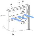
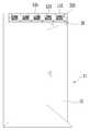
도 1은 종래기술의 방화문을 보여주는 도면이다. 도 2는 종래기술의 방화문에서 방화문이 닫힌 상태에서 통풍도어에 유동압력이 가해지는 상태를 보여주는 도면이다.1 is a view showing a conventional fire door. 2 is a view showing a state in which a flow pressure is applied to a ventilation door in a state in which a fire door is closed in a fire door of a related art.
한편, 상기와 같은 문제점을 해소하기 위해 제안된 기술로 한국등록특허 제10-1826906호(이하 '종래기술'로 지칭)가 제안된 바 있다. 이때, 종래기술은 방화문의 상측에 추가적으로 설치되는 배연구(21)와 배연구(21) 내에 설치되는 통풍도어(20)를 설치한 구조를 제안하고 있다.Meanwhile, Korean Patent No. 10-1826906 (hereinafter referred to as "prior art") has been proposed as a proposed technique to solve the above problems. At this time, the prior art has proposed a structure in which a
구체적으로, 도 1 및 2를 참고하면, 종래기술의 통풍도어(20)는 급기댐퍼(1)에 의해 송풍이 이루어지는 경우 계단실(A: 제연구역)과 복도(비제연구역) 간의 압력차이로 인해 상기 방화문의 도어(10)가 완벽하게 닫히지 않는 현상이 발생하는 것을 방지하기 위해 도어(10)이 닫히기 전에 계단실의 공기가 통풍도어(20)를 복도로 유동되도록 함으로써 도어(10)가 닫히도록 한다. 그리고 도어(10)가 닫히면 통풍도어가 닫히도록 한다.1 and 2, the
그러나, 이러한 구조를 갖는 종래의 방화문은 다음과 같은 문제점이 있다.However, the conventional fire door having such a structure has the following problems.
첫째로, 종래기술은 복도와 계단실을 구획하는 벽에 설치되는 방화문에 적용되는 경우에 통풍도어(20)는 화재 상황에서 폐쇄 작동이 상당히 어려운 문제가 있다.First, when the prior art is applied to a fire door installed on a wall partitioning a hallway and a staircase, the
보다 상세히 설명하면, 복도 측의 화재 발생 시, 계단실측을 제연구역으로 형성하기 위해 계단실 측에 위치된 급기댐퍼(1)가 가동하면, 종래기술에서 언급하고 있는 바와 같이 계단실과 복도의 압력차에 의해 도어(10)가 완벽히 닫히지 않는 상황이 발생될 수 있다. 이때, 도어가 완벽히 닫히지 못하는 이유는 압력차 즉, 급기댐퍼(1)에 의해 계단실에 존재하는 공기의 압력이 높고 이 압력에 의해 공기가 도어(10)의 개방공간인 도어(10)와 도어프레임(11) 사이로 유동되고 이에 유동되는 공기에 의해 상대적으로 도어(10)가 열리는 방향으로 힘(=공기의 유동압력)을 받고 있는 상태가 되기 때문이다.More specifically, if the air supply damper (1) located on the staircase side is operated to form the stepped room side at the staircase side when a fire occurs in the hallway side, as described in the related art, the pressure difference between the staircase and the hallway A situation may occur in which the
이러한 상태에서 통풍도어(20)를 개방하면 완벽이 닫히지 않은 도어(10) 틈을 통해 유동되는 공기가 유출면적이 상대적으로 넓은 배연구(21)를 통해 대부분 유동됨에 따라 도어(10)어와 도어프레임(11) 사이를 통해 유동하는 공기의 유동량이 낮아지고, 이에 따른 유동압력이 저하됨으로써 도어(10)가 닫힐 수 있게 된다.In this state, when the
그러나, 도 2를 기준으로 도어(10)가 완벽히 닫히지 못할 정도의 압력차가 발생되는 상황, 즉, 도어(10)가 완벽히 닫히지 못할 정도의 계단실에서 복도로의 공기의 유동에 따른 유동압력이 발생된 상황에서 통풍도어(20)를 개방한 후, 도어(10)를 닫으면, 다시 제연구역의 차압은 상승하게 된다. 그리고, 이러한 차압에 따른 공기 유동은 배연구(21)를 통해 빠져나감에 따라 배연구(21)에 유동압력이 가해지게 되고 통풍도어(20) 폐쇄 방향은 이러한 유동압력이 방향과 정 반대임에 따라 통풍도어(20)의 폐쇄 시에는 배연구(21)를 통과하는 공기에 의한 유동압력을 이겨내야만 가능하다. 또한, 도어(10)의 닫힘과 동시에 제연구역이 차압이 급격히 높아지지 않더라도, 통풍도어(20)가 닫히는 과정에서 배연구의 틈(면적)이 작아지는 만큼 제연구역의 차압은 점차적으로 상승하게 됨에 따라 통풍도어(20)에 가해지는 유동압력을 이겨내지 않는 한, 차압에 의해 도어(10)가 닫히지 않는 이전 상황이 똑같이 재연될 수 있다.However, when a pressure difference is generated such that the
따라서, 통풍도어(20)를 통해 유동되는 공기의 유동압력을 이겨내고 통풍도어(20)가 폐쇄되기 위해서는 상당한 힘을 발생시키는 구동장치가 적용되어야 함으로써 구동장치의 비용이 높아지게 되어 효율적이지 못한 문제점이 있다.Therefore, a driving device that generates a considerable force is required to overcome the flow pressure of the air flowing through the
둘째로는, 통풍도어(20)에 의한 배연구(21)의 밀폐성능이 완벽하지 못한 문제점이다. 구체적으로, 상기에서 언급한 바와 같이 복도에서 화재가 발생되어 방화문이 닫히지 못할 정도의 차압이 발생되는 상황에서 도어(10)가 닫힌 경우, 계단실에 형성된 차압은 통풍도어(20)에 작용한다. 이때, 통풍도어(20)가 폐쇄된 상태라면 차압에 의해 통풍도어(20)가 개방되는 방향으로 지속적인 힘을 받게 되고, 통풍도어(20)는 단순 개폐암(22)에 의해 일측이 지지되는 구조임에 따라 개폐암(22)에 의해 지지되는 반대지점 및 통풍도어(20)의 하측 등은 개방되는 방향으로의 이동을 방지하기 위한 별도의 고정구조가 없어 통풍도어(20)가 개방되거나, 완전히 개방되지 않더라도 틈이 발생될 가능성이 존재한다. 따라서, 통풍도어(20)에 틈이 발생 되면, 발생된 틈을 통해 공기가 빠져나가 계단실에 기준 차압이 형성되지 않아 화염, 연기 및 유동가스 등이 유입될 수 있어 방화문의 기능이 무력화될 수 있다. Secondly, the sealing performance of the ventilation door (20) is not perfect. Specifically, as described above, when the
셋째로는 종래기술의 가장 큰 문제점으로 방화문의 설치 시, 통풍도어(20)의 설치를 위한 설치 면적을 확보해야 한다는 것이다. 일반적으로 계단실과 복도 사이에 설치되는 방화문 설치면적은 대부분 건물의 각 층의 형성 높이에 맞도록 설계되며, 이에 맞게 방화문이 제작 및 설치된다. 이는 방화문의 면적을 층간 높이에 근접하게 하여 사람 또는 화물(짐)의 이동이 용이하게 이루질 수 있도록 하기 위함이다. 그러나, 종래기술의 경우 방화문의 상측으로 배연구(21) 및 통풍도어(20)를 설치해야 함에 따라 부가적인 면적이 요구되며, 이에 방화문의 면적(크기)가 작아질 수 밖에 없는 문제가 있기 때문에 종래기술의 방화문의 경우 그 적용성에 한계가 있으며, 기존 설치된 일반적인 방화문에 적용하기 위해서는 그 설치비용 또한 상당히 소요되는 문제점이 있다.Thirdly, the biggest problem of the prior art is that the installation area for installation of the
넷째로는 도어 및 통풍도어가 닫히면 계단실의 차압이 기준치 이상으로 급격히 상승한다는 것이다. 즉, 제연설비인 급기댐퍼에는 비제연구역인 계단실의 차압이 40Pa ~ 60Pa 이내가 되도록 함으로써 제연구역에 연기 및 가스가 유입되지 못하도록 하는 것이나, 방화문의 도어 및 통풍도어가 모두 닫히면 계단실 또는 전실이 밀폐공간이 되어 내부의 압력이 짧은 시간(약 2~3초 사이)에 급격히 높아지게 된다. 이때, 계단실에 형성되는 방화문은 복도에서 계단실로 들어올 수 있는 방화문(복도와 계단실 사이에 형성 이하 '제 1 방화문')과 계단실에서 계단이 형성된 비상통로 나가는 방화문(계단실과 계비상통로 사이에 형성 이하 '제 2 방화문')이 있는데 이 두 방화문의 도어가 열리는 방향은 동일하게 형성하게 된다. 따라서 제연구역인 계단실에 사람이 존재한 상황에서 제 1 방화문의 도어 및 통풍도어가 닫히게 되면 제 2 방화문의 도어는 계단실의 차압에 의해 열지 못하게 되는 문제점이 있다. 이러한 문제점과 관련하여 종래기술에서는 도어에 형성된 레버나, 근접식 센서에 의해 통풍도어를 개방시킬 수 있는 것으로 개시하고 있으나 구체적인 개시가 없으며, 근본적으로 레버나 근접식 센서와 통풍도어를 개방시키기 위한 피난인의 별도의 조작이 요구된다는 점에서 그 실효성에 의구심이 발생되며, 전반적으로 레버의 연동 또는 센서설치 시 구조적 설계가 복잡해지는 단점이 있다.Fourth, when the door and the ventilation door are closed, the differential pressure in the staircase rises sharply above the reference value. That is, in order to prevent smoke and gas from entering the ventilation area by allowing the pressure difference of the staircase to be within the range of 40 Pa to 60 Pa in the air supply damper, which is a ventilation facility, the ventilation damper or the doors and ventilation doors of the fire doors are closed, And the internal pressure rapidly increases in a short time (about 2 to 3 seconds). At this time, a fire door formed in the staircase is formed between a fire door (a first fire door formed between the hall and the staircase) that can enter the staircase from the hallway, and an escape passage with a staircase formed in the staircase 'Second fire door'), and the doors of these two fire doors are formed in the same direction. Therefore, when the door of the first fire door and the vent door are closed in a situation where a person is present in the staircase which is a smoke-free zone, the door of the second fire door may not be opened due to the differential pressure of the staircase. In connection with such a problem, in the prior art, it has been disclosed that the ventilation door can be opened by a lever or a proximity sensor formed on the door, but there is no specific disclosure, and fundamentally there is no evacuation for opening the lever, the proximity sensor, There is a disadvantage in that the structural design is complicated when the lever is interlocked or the sensor is installed.
본 발명은 상기에서 언급한 문제점을 해소하기 위해 안출된 것으로, 복도와 계단실을 연결하는 전실상에 설치되는 방화문에 있어서 화재에 따른 차압 발생 시, 차압을 해소하여 방화문의 안정적인 개폐가 이루어질 수 있음과 동시에 완벽한 기밀을 유지하여 가스 및 연기가 제연구역으로 유입되지 않으며, 제연구역인 계단실의 차압이 자동적으로 항상 일정한 범위로 유지될 수 있도록 하는 방화문을 제공하고자 한다.The present invention has been devised to overcome the above-mentioned problems, and it is an object of the present invention to provide a fire door provided on a front passenger seat that connects a hall and a staircase to reliably open a fire door by eliminating a pressure difference, At the same time, it is intended to provide a fire door that maintains perfect airtightness so that gas and smoke do not flow into the smoking area, and the pressure difference in the staircase, which is the smoking area, is automatically maintained in a constant range.
본 발명에 따르면, 내부에 공간을 갖는 중공형의 사각프레임으로 상기 벽체에 설치되는 도어 프레임; 자동클로저 장치에 의해 개폐가 가능하도록 상기 도어프레임에 설치되는 도어; 및 상기 도어프레임의 상측 프레임 내부에 설치되는 차압조절장치;를 포함하여 형성되되, 상기 상측 프레임에는 제연구역을 향하는 일 측면이 개폐 가능하도록 하는 커버와, 상기 커버 및 상기 커버와 대향되는 타측면에 길이방향을 따라 일정간격 이격되어 형성되는 복수개의 유동홀과, 상기 상측 프레임 내측의 유동홀의 테두리를 따라 수직하게 연장되는 형태의 밀폐부가 형성되고, 상기 차압조절장치는, 상기 상측 프레임의 내측에 길이방향으로 배치되는 회전축과, 라운드지게 절곡 가공된 평판형의 플레이트로 상기 각 밀폐부와 대응되는 지점에서 회전축과 연결바에 의해 연결되어 상기 회전축의 회전에 의해 상기 밀폐부를 개방 및 폐쇄하는 밀폐판으로 형성되는 차단부와, 상기 상측 프레임의 내부 일측에 배치되어 상기 회전축과 연결되는 기어박스와, 상기 상측 프레임에 설치되어 기어박스와 연결되는 모터와, 상기 커버에 설치되어 계단실의 차압을 측정하는 차압감지센서, 및 상기 상측 프레임 내부에 설치되고, 상측 프레임의 저면을 통해 노출되어 도어 폐쇄 시, 도어의 상면과 접촉되는 구동 스위치가 일체로 형성되며, 상기 차압감지센서 및 상기 모터와 전기적으로 연결되어 상기 구동 스위치의 눌림 및 차압감지센서에 의한 값에 의해 상기 모터의 구동을 제어하여 상기 차단부에 의한 밀폐부의 밀폐 정도를 선택적으로 조절하는 컨트롤 박스를 포함하여 구성되는 것을 특징으로 하는 방화문이 제공될 수 있다.According to the present invention, there is provided a door frame comprising: a hollow rectangular frame having a space therein; A door installed in the door frame so as to be opened and closed by an automatic closing device; And a differential pressure regulating device installed inside the upper frame of the door frame, wherein the upper frame is provided with a cover for opening and closing one side of the upper frame toward the smoke inducing section, A plurality of flow holes formed at predetermined intervals along the longitudinal direction and a sealing portion extending vertically along the rim of the flow hole at the inside of the upper frame are formed in the inside of the upper frame, And a sealing plate which is connected to the rotary shaft by a connecting bar at a position corresponding to each of the sealing portions and is opened and closed by rotation of the rotary shaft by a rotation of the rotary shaft A frame disposed at one side of the upper frame and connected to the rotation shaft, A motor mounted on the upper frame and connected to the gear box, a differential pressure sensor installed on the cover and measuring a differential pressure of the staircase, and a sensor installed in the upper frame, And a drive switch which is in contact with the upper surface of the door when the motor is closed, and the drive of the motor is controlled by the pressure difference sensor and the motor, And a control box for selectively controlling the degree of sealing of the hermetically sealed portion by the blocking portion.
본 발명에 따른 방화문은 화재의 발생 시, 비제연구역과 제연구역인 복도와 계단실을 구획하는 방화문이 압력차이(차압)에 따라 완벽히 닫히지 않거나 열지지 않는 경우 방화문의 상측 프레임 내에 설치된 차압조절장치에 의해 도어에 가해지는 차압을 해소함으로써 도어의 완벽한 닫힘 또는 개방이 용이하게 이루어질 수 있는 효과가 있다.The fire door according to the present invention is characterized in that, when a fire occurs, the fire door, which separates the non-fire area and the smoking halls from the corridor and the staircase, is not completely closed or opened due to a pressure difference (differential pressure) There is an effect that the door can be completely closed or opened easily by eliminating the differential pressure applied to the door.
또한, 차압조절장치는 제연구역의 밀폐를 위해 닫힌 상태에서 비제연구역과 제연구역의 압력차이가 크게 발생하는 경우 및 지속적인 압력차가 유지되는 동안도 차압 해소를 위한 통로인 유동홀의 밀폐력의 저하가 방지됨에 따라 급격히 상승하는 차압에 의해 유동홀의 틈 발생 등에 의해 화염, 연기, 유독가스가 유출되어 다른 층으로 확산되는 것이 원천적으로 방지되는 효과가 있다.In addition, the differential pressure regulating device prevents the lowering of the sealing force of the flow hole, which is the passage for solving differential pressure, when the pressure difference between the non-reactor station and the smoke-removing zone is large and the continuous pressure difference is maintained. There is an effect that the flame, smoke, and toxic gas are flown out due to the occurrence of a gap in the flow hole due to a suddenly increasing differential pressure and are prevented from diffusing to other layers.
또한, 제연구역의 차압이 급격히 높아지는 경우, 차압감지센서가 이를 감지하고 이를 기반으로 차압조절장치를 작동시켜 설정 범위의 차압이 형성되도록 함으로써 피난인의 별도의 조작 없이도 제연구역의 차압이 항상 일정한 수준으로 유지될 수 있기 때문에 긴급한 상황에서의 피난민에 의한 도어의 개방 및 폐쇄가 즉시 이루어질 수 있다.Further, when the differential pressure in the smoke-inducing zone is suddenly increased, the differential pressure sensor senses it and operates the differential pressure regulator based on the differential pressure sensor to generate a differential pressure in the set range, so that the differential pressure in the smoke- It is possible to immediately open and close the door by the refugee in an emergency situation.
아울러, 차압조절장치는 방화문을 형성하는 도어프레임의 상측 프레임에만 설치됨에 따라 비교적 적은 설치면적이 요구되며, 기존에 설치된 일반적인 방화문에 적용하기 위해서는 도어프레임의 상측 프레임만 교체 또는 부분 시공을 통해 적용하면 됨에 따라 전반적인 시공 비용 및 시간 또한 절감될 수 있어 그 적용성이 높은 장점이 있다.In addition, since the differential pressure regulating device is installed only on the upper frame of the door frame forming the fire door, a comparatively small installation area is required. In order to apply to the conventional fire door, the upper frame of the door frame is only replaced or partially applied The overall construction cost and time can be reduced, which is advantageous in its applicability.
도 1은 종래기술의 방화문을 보여주는 도면이다.
도 2는 종래기술의 방화문에서 방화문이 닫힌 상태에서 통풍도어에 유동압력이 가해지는 상태를 보여주는 도면이다.
도 3은 본 발명에 따른 방화문을 보여주는 도면이다.
도 4는 본 발명에 따른 방화문의 상측 프레임 및 차압조절장치를 보여주는 도면이다.
도 5는 본 발명에 따른 밀폐부를 보여주는 도면이다.
도 6은 본 발명에 따른 차압조절장치의 작동 예시를 보여주는 도면이다.
도 7은 본 발명에 따른 차압조절장치가 설치되는 상측 프레임에 구동 스위치가 노출되어 설치된 상태를 보여주는 도면이다.1 is a view showing a conventional fire door.
2 is a view showing a state in which a flow pressure is applied to a ventilation door in a state in which a fire door is closed in a fire door of a related art.
3 is a view showing a fire door according to the present invention.
4 is a view showing an upper frame and a differential pressure control device of a fire door according to the present invention.
FIG. 5 is a view showing an enclosure according to the present invention.
6 is a view showing an operation example of the differential pressure regulating device according to the present invention.
7 is a view showing a state in which a drive switch is exposed to an upper frame on which a differential pressure regulating device according to the present invention is installed.
본 발명의 이점 및 특징, 그리고 그것들을 달성하는 방법은 첨부되는 도면과 함께 상세하게 후술되어 있는 실시예들을 참조하면 명확해질 것이다.BRIEF DESCRIPTION OF THE DRAWINGS The advantages and features of the present invention, and the manner of achieving them, will be apparent from and elucidated with reference to the embodiments described hereinafter in conjunction with the accompanying drawings.
그러나 본 발명은 이하에서 개시되는 실시예들에 한정되는 것이 아니라 서로 다른 다양한 형태로 구현될 수 있으며, 단지 본 실시예들은 본 발명의 개시가 완전하도록 하고, 본 발명이 속하는 기술분야에서 통상의 지식을 가진 자에게 발명의 범주를 완전하게 알려주기 위해 제공되는 것이며, 본 발명은 청구항의 범주에 의해 정의될 뿐이다. 명세서 전체에 걸쳐 동일 참조 부호는 동일 구성 요소를 지칭한다.The present invention may, however, be embodied in many different forms and should not be construed as limited to the embodiments set forth herein. Rather, these embodiments are provided so that this disclosure will be thorough and complete, and will fully convey the scope of the invention to those skilled in the art. To fully disclose the scope of the invention to those skilled in the art, and the invention is only defined by the scope of the claims. Like reference numerals refer to like elements throughout the specification.
이하, 본 발명이 속하는 기술 분야에서 통상의 지식을 가진 자가 용이하게 실시할 수 있도록 본 발명의 실시예에 대하여 첨부한 도면을 참고로 하여 상세히 설명한다. 그러나 본 발명은 여러 가지 상이한 형태로 구현될 수 있으며 여기에서 설명하는 실시예에 한정되지 않는다. 명세서 전체를 통하여 유사한 부분에 대해서는 동일한 도면 부호를 부가하며, 종래기술의 기술요소와 동일하거나 일반적인 기술요소에 대해서는 그 설명을 생략하거나 간략화 하였다.Hereinafter, embodiments of the present invention will be described in detail with reference to the accompanying drawings so that those skilled in the art can easily carry out the present invention. The present invention may, however, be embodied in many different forms and should not be construed as limited to the embodiments set forth herein. Throughout the specification, like parts are denoted by like reference numerals, and description of the same or common technical elements as those of the prior art is omitted or simplified.
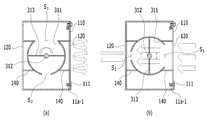
도 3은 본 발명에 따른 방화문을 보여주는 도면이다. 도 4는 본 발명에 따른 방화문의 상측 프레임(11a) 및 차압조절장치(300)를 보여주는 도면이다. 도 5는 본 발명에 따른 밀폐부(140)를 보여주는 도면이다.3 is a view showing a fire door according to the present invention. 4 is a view showing an
도 3 내지 5를 참고하면, 본 발명에 따른 방화문은 아파트, 공동주택, 병원과 같은 건축물에 화재가 발생할 경우, 화염, 연기, 유독가스 등이 다른 곳으로 확산되는 것을 방지하는 것으로, 도어(10), 도어프레임(11), 차압조절장치(300)를 포함한다.3 to 5, the fire door according to the present invention prevents fire, smoke, and toxic gas from diffusing to other places when a fire occurs in a building such as an apartment, a residence, a hospital,
상기 도어(10)는 건축물의 복도와 계단실(=전실)을 구획 및 연결하는 벽체 또는 계단실(=전실)과 비상통로를 구획하는 벽체에 설치되는 것으로 내화성이 우수한 공지의 재료로 제작될 수 있으며, 세트로 제작되는 도어프레임(11)에 그 일측이 경첩을 통해 결합되어 회전 각도에 따라 비상구의 일부 또는 전체를 개방하거나 폐쇄한다. 아울러, 상기 도어(10)의 중앙부분에는 일반적인 도어(10)와 같이 내부로 인입되거나 외부로 인입되는 구조의 도어래치가 형성된다. 이러한 도어(10)는 공지된 자동클로저(30) 장치를 통해 비상구를 자동으로 개폐할 수 있다.The
상기 도어프레임(11)은 상/하측 프레임과 좌/우측 프레임으로 구성되는 공지된 구조의 일방적인 도어프레임(11)으로, 좌/우 프레임 중 어느 하나의 프레임의 중앙부분에는 도어(10) 가 완전히 닫힐 경우 상기 도어래치가 인입되는 걸림홈이 형성된다.The
다만, 본 발명은 공지된 도어프레임(11)과 비교하여 도어프레임(11)의 상측에 배치되는 상측 프레임(11a)에 있어서 기술적 특징이 있는 바, 상측 프레임(11a)에 대해서 중점적으로 설명하기로 한다.The
상기 상측 프레임(11a)은 내부에 차압조절장치(300)가 수용될 수 있도록 공간을 갖는 중공형의 사각 프레임으로 형성되며, 커버(110)와, 유동홀(120) 및 밀폐부(140)가 형성된다.The
먼저, 상측 프레임(11a)은 기본적으로 중공형의 사각프레임 형태로 이루어지되, 제연구역인 계단실을 향하는 일 측면은 길이방향을 따라 소정 부분이 개방되도록 절개 형성된다. 그리고 이 절개 형성된 테두리 부분에는 내측으로 절곡 연장된 밀폐리브(11a-1)들이 형성되고 밀폐리브(11a-1) 주변으로는 일정간격으로 제 1 볼트홀(11a-2)이 형성된다.First, the
상기 커버(110)는 상측 프레임(11a)의 개방된 일 측면에 힌지 결합되어 상측 프레임(11a)의 개방된 일 측면을 개방 및 폐쇄하는 것으로, 내측면에는 닫힘 시 밀폐리브(11a-1)와 접촉되는 제 1 밀폐부재(111)가 형성되며 이때 제 1 밀폐부재(111)는 고무 패킹일 수 있다. 또한, 커버(110)와 상측 프레임(11a) 일측과의 힌지 결합되는 측면을 제외하고, 상기 제 1 밀폐부재(111)의 외측 주변에는 상기 제 1 볼트홀(11a-2)과 대응되는 위치에 제 2 볼트홀(112)이 형성된다. 따라서, 커버(110)가 닫히는 경우 제 1 밀폐부재(111)는 밀폐리브(11a-1)에 접하며, 상호 일치되는 제 1 및 2 볼트홀(11a-1, 112)에 볼트(B) 등의 결합부재를 통해 결합함으로써, 상측 프레임(11a) 내부가 밀폐되도록 커버(110)의 개폐가 이루어질 수 있다. 또한, 커버(110)에는 추가적으로 차압감지센서(350)가 설치될 수 있는 차압센서 설치홀(113)이 형성되고 이 차압센서 설치홀(113)에는 후술된 차압감지센서(350)가 설치된다. The
상기 유동홀(120)은 사각형의 홀 구조로, 상측 프레임(11a)의 계단실과 복도방향으로 각각 노출되는 양 측면 즉, 상측 프레임(11a)의 일 측면인 커버(110)와, 커버와 대향된 타측면에 길이방향을 따라 일정간격으로 이격되어 형성되며, 상측 프레임(11a)의 양 측면에 형성된 유동홀(120)은 상호 상측 프레임(11a)의 폭방향으로 동일선상의 위치되도록 복수개가 가공(관통) 형성된다. 이러한 유동홀(120)은 차압을 해소하기 위한 공기 유입구 및 유출구로 적용되며, 각 유동홀(120)에는 이물질의 유입 및 내부에 설치되는 차압조절장치(300)의 보호를 위해 보호망이 설치된다.The
상기 밀폐부(140)는 상기 유동홀(120)에 형성되어 유입 또는 유출되는 공기의 유동통로로 적용되는 것으로, 도 5로 도시된 바와 같이 상측 프레임(11a) 내측의 유동홀(120)의 테두리를 따라 수직하게 연장 형성되는 복수의 플레이트에 의해 이루어진다. 구체적으로, 밀폐부(140)는 유동홀(120)의 상측 및 하측을 따라 수평하게 배치되는 상/하측 플레이트(141, 142)와 유동홀(120)의 좌/우측을 따라 수직하게 배치되어 상/하 플레이트(141, 142)의 끝단과 연결되는 좌/우측 플레이트(143, 144)로 구성된다. 이때, 상/하/좌/우 플레이트(141~144)는 전반적으로 소정의 두께를 가지고 상측 프레임(11a)의 내부 중앙을 향하는 각 플레이트의 일단의 접촉면(141a~144a)은 밀폐판(311)의 외면과 기밀하게 접할 수 있도록 라운드지게 가공 된다.5, the hermetically sealed
또한 밀폐부(140)의 라운드지게 가공된 각 플레이트(141~144) 일단의 각 접촉면(141a~144a)에는 길이방향을 따라 제 2 밀폐부재(146)가 삽입되어 고정될 수 있는 밀폐부재 고정홈(145)이 가공 형성된다.The
이때, 제 2 밀폐부재(146)는 각 접촉면(141a~144a)과 밀폐판(311)과 접촉 시, 접촉지점의 기밀상태가 유지되도록 하기 위한 구성으로, 각 접촉면(141a~144a)의 면적과 대응되는 면적을 갖는 편평한 베이스(146a)와, 상기 베이스(146a)의 후면에 길이방향을 따라 형성되어 상기 밀폐부재 고정홈(145)에 견고하게 삽입되는 고정리브(146b)와, 상기 베이스(146a)의 전면에 베이스(146a)의 길이방향을 따라 형성되고 폭방향으로 일정 간격 이격되어 돌출 형성되는 복수개의 접촉리브(146c)로 이루어진다.The
이때, 고정리브(146c)는 각 접촉면(141a~144a)에 형성된 밀폐리브 고정홈(145)에 단순 끼움방식으로 결합됨에 따라 제 2 밀폐리브(146)의 설치, 보수를 위한 교체가 용이한 장점이 있다.Since the fixed
또한, 접촉리브(146c)에 있어서, 밀폐판(311)과의 접촉 시, 밀폐부(140)와의 밀폐력을 향상시키기 위한 구조이며, 구체적으로 밀폐판(311)은 밀폐부(140) 일단의 접촉면(141a~144a)에 형성된 제 2 밀폐부재(146)와 접촉된 상태로 회전되는데, 접촉리브(146c)가 없는 상태에서는 밀폐판(311)과 제 2 밀폐부재(146)는 면접촉 한 상태가 되고, 제 2 밀폐부재(146)가 고무와 같은 재질로 이루어짐에 따라 밀폐판(311)의 회전 시, 마찰 저항이 크게 작용된다. 그러나, 복수개의 접촉리브(146c)를 형성하면, 밀폐판(311)과 제 2 밀폐부재(146)가 선접촉이 이루어짐에 따라 마찰저항이 감소되고, 각 접촉리브(146c)의 형성 수만큼 중첩(리브가 2~4개 형성 시, 2 ~4 중 밀폐)되는 만큼 밀폐력 또한 보장될 수 있다. 또한, 접촉리브(146c) 중 어느 하나가 손상되더라도 다른 접촉리브(146c)에 밀폐력이 유지될 수 있음에 따라 제 2 밀폐부재(146)의 사용 기간(내구성) 또한 증대될 수 있다.The sealing
이러한, 밀폐부(140)는 각 유동홀(120)로부터 상측 프레임(11a)의 중심 방향으로 돌출되는 구조를 취하게 됨으로써 상측 프레임(11a)의 일 측면에 형성된 유동홀(120)을 통해 유입된 공기는 상측 프레임의 폭방향으로 위치된 동일선상의 밀폐부(140)들을 순차적으로 지나 타 측면에 위치된 유동홀(120)을 통해 배출되는 구조를 가지게 된다.The hermetically sealed
아울러, 밀폐부(140)는 밀폐부(140) 없이 밀폐판(311)이 단순히 유동홀(120)에 접촉하는 구조와 비교하여 상대적으로 유동홀(120)의 형성 면적을 확장할 수 있는 효과가 있다. 즉, 밀폐부(140)가 생략된 경우, 곡선형태로 가공된 밀폐판(311)과 상측 프레임(11a)의 내면은 선접촉으로 접하게 되어 유동홀(120)을 완벽한 밀폐를 위해서는 유동홀(120)의 면적이 상대적으로 작게 형성될 수 밖에 없다. 이에 밀폐부(140)를 적용함으로써 유동홀(120)의 면적을 넓게 형성할 수 있고, 따라서, 유동홀(120)을 통한 공기 유동량의 증가에 따른 차압 하강이 빠르게 이루어질 수 있다.The sealing
또한, 방화문의 사이즈에 따라 도어프레임(11)이 적용됨에 따라 상측 프레임 폭 또한 다양한 사이즈로 변경될 수 있음을 감안할 때, 일률적인 구조 및 사이즈의 차압해소장치(30)를 적용한 상태에서 밀폐부(140)만을 변경적용함으로써 다양한 규격의 사이즈를 갖는 방화문에도 차압 해소 기능을 갖도록 할 수 있다.In addition, considering that the upper frame width can be changed to various sizes as the
상기 차압조절장치(300)는 앞서 언급된 바와 같이 상측 프레임(11a) 내부에 장착되어 상기 밀폐부(140)를 선택적으로 개방 및 폐쇄함으로써 유동홀(120)과 밀폐부(140)를 통한 공기의 유동을 제어하는 장치이다. 이러한 차압조절장치(300)는 차단부(310), 기어박스(320), 모터(330), 컨트롤 박스(340) 및 차압감지센서(350)로 구성된다.The differential
차단부(310)는 상측 프레임(11a)의 폭방향으로 상호 대칭되어 배치되는 밀폐부(140)에 접하여 회전에 의해 각 밀폐부(140)를 선택적으로 개폐하는 구성으로, 밀폐판(311), 회전축(312) 및 연결바(313)로 이루어진다.The blocking
상기 밀폐판(311)은 밀폐부(140)의 각 플레이트(141~144)의 일 단에 접하는 것으로, 밀폐부(140)의 면적 이상의 면적으로 형성되며, 라운드지게 가공된 플레이트 구조를 취한다. 이때, 밀폐판(311)의 라운드진 정도는 밀폐부(140)의 각 플레이트(141~144)의 라운드지게 가공된 일단의 접촉면(141a~144a) 곡률과 대응된다. 이러한 밀폐판(311)은 밀폐부(140)의 접촉면(141a~144a)과 접하여 선택적으로 밀폐부(140)를 폐쇄하거나 개방되도록 하기 위해 상측 프레임(11a)의 폭방향으로 각각 한 쌍이 배치되며, 상측 프레임(11a)의 길이방향을 따라 유동홀(120)의 수만큼 형성된다.The sealing
또한, 상기 밀폐판(311)은 상호 이격되어 회전축(312)을 중심으로 상호 대칭되게 배치되어 연결바(313)에 의해 연결되며, 연결바(313)를 기준으로 대칭되어 배치되는 밀폐판(311) 사이의 공간(S1, S2)을 통해 공기가 유동될 수 있게 된다.The sealing
이때, 연결바(313)를 중심으로 상호 대칭되게 배치되는 밀폐판(311) 사이의 공간에 있어서, 계단실측 방향(도 4 기준 우측 방향)의 공간(S1)은 복도측 방향(도 4 기준 좌측 방향)의 공간(S2)에 비해 상대적으로 크게 형성된다. 즉, 밀폐판(311)이 연결바(313)를 통해 회전축(312)에 연결 시, 밀폐판(311)의 중심에 연결되지 않고 일측으로 치우친 위치에 형성됨으로써 연결바(313)를 중심으로 대칭되게 형성되는 양측의 공간(S1, S2)의 크기가 다르게 형성된다.At this time, in the space between the sealing
이렇게 연결바(313)를 중심으로 대칭되게 형성되는 양측의 공간(S1, S2)의 크기가 다르도록 하는 점은 복도측으로 유출되는 공기의 속도를 증가시키기 위함이다. 즉, 차단부(310)의 회전에 의해 밀폐판(311) 사이의 공간(S1, S2)이 밀폐부(140)와 동일선상이 되도록 하여 밀폐부(140)가 개방되도록 하면 차압에 의해 계단실에서 복도 방향으로 공기가 유동하게 된다. 이때, 상대적으로 복도측 밀폐판(311) 사이의 공간(S2)이 좁음으로써 유출 속도가 증가되어 배출되게 된다. 따라서, 도어(10)의 상측 지점인 상측 프레임(11a)을 통해 배출되는 공기의 속도가 증가되어 마치 에어커튼과 같은 기능을 하게 되고 복도의 천정에 존재하는 연기 등이 방화문이 설치된 벽체를 타고 순환하여 방화문을 가리는 것이 방지되도록 할 수 있다.The difference in size of the spaces S1 and S2 on both sides symmetrically formed around the connecting
상기 회전축(312)은 상기 밀폐판(311)을 일괄적으로 회전시키기 위한 것으로, 상측 프레임(11a)의 길이 방향으로 배치되고, 일단 측은 상측 프레임(11a)의 내측에서 베어링 등에 의해 회동 가능하도록 단순 지지되고, 타단 측은 기어박스(320)에 연결된다.The
상기 기어박스(320)는 모터(330)와 회전축(312)을 연결 시켜주는 것으로, 상측 프레임(11a)의 공간 사용 효율상 베벨 기어박스일 수 있다. 기어박스(320)는 별도의 케이스에 의해 밀폐형으로 형성되어 있음에 따라 내부의 안정적인 윤활물질이 존재하도록 하고, 화재 시, 열에 의한 윤활물질의 연소(소모)를 최소화시킬 수 있음과 동시에 이물질의 투입이 원천적으로 방지됨으로써 전반으로 작동성 및 내구성이 증대될 수 있다. 또한, 방화문의 사이즈에 따른 차압조절장치(300)의 규격에 따라 다양한 규격의 기어박스가 변경되어 적용될 수 있다. 따라서, 차압조절장치(300)별 규격이 다른 경우 상대적으로 가격이 비싼 모터의 변경대신 기어비가 다른 기어박스(320)를 변경적용 함으로써 전반적인 방화문의 제조 원가가 절감될 수 있다.The
상기 모터(330)는 통상적인 공지의 모터가 적용될 수 있는 바, 구체적인 설명은 생략하기로 한다.The
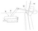
상기 컨트롤 박스(340)는 상기 모터(330)와 전기적으로 접속되어 모터의 가동을 제어하는 것으로, 상측 프레임(11a) 내부의 기어박스(320) 주변에 배치된다. 또한, 컨트롤 박스(340)의 저면에는 구동 스위치(341)가 형성되어 있으며, 이 구동 스위치(341)는 상측 프레임(11a) 저면을 통해 외부로 노출된다. 이러한 구동 스위치는 도어(10)가 닫히는 과정 중에 도어(10)의 상면과 구동 스위치가 접촉하게 되어 구동 스위치가 눌리게 되면 컨트롤 박스(340)가 모터(330)를 작동시키게 된다. 이때, 구동 스위치(341)는 종래기술에도 개시되어 있는 구성으로 그 기능 및 목적 측면에서는 상당히 유사한 측면이 있으나, 구동 스위치(341)가 컨트롤 박스(340)에 형성되어 도어(10)의 상면과 접촉되는 점에서, 컨트롤 박스(340)와의 연결을 위한 배선작업이 불필요하고, 구동 스위치(341)의 설치를 위한 좌/우측 중 어느 하나의 프레임의 구동 스위치(341) 형성 공간과 같은 추가적인 가공이 요구되지 않는 점에서 종래기술과 차별회된 장점이 있다. 또한, 구동 스위치(341)가 상측 프레임(11a)에 설치되어 있음에 따라 중력에 의해 구동 스위치(341)가 노출되도록 돌출됨으로써 종래기술과 같이 구동 스위치(341)가 항상 돌출되도록 하기 위한 탄성부재가 반드시 적용되지 않아도 됨에 따라 구조의 단순화가 가능하고 비용적인 측면에서 절감되는 효과가 있다.The
상기 차압감지센서(350)는, 제연구역인 계단실의 차압을 측정하는 것으로, 상측 프레임(11a)의 일면에 컨트롤 박스(340)와 전기적으로 연결되도록 설치된다. 이러한 차압감지센서(350)는 제연구역인 계단실의 차압을 지속적으로 모니터링하여 급기댐퍼에 의한 계단실의 과도한 차압 형성 시, 측정된 차압의 값을 컨트롤 박스(340)에 전달하고 컨트롤 박스(340)는 전달받은 차압값의 수치에 따라 설정된 만큼의 범위로 모터(330)를 구동시켜 차단부(310)에 의한 밀폐부(140)의 폐쇄 상태를 해제한다. 즉, 일 예로, 계단실이 밀폐되어 계단실의 차압이 급격하게 높아지게 되며, 계단실의 차입이 높아지는 경우, 차압감지센서(350)가 이를 감지하여 컨트롤 박스(340)에 전달하고, 컨트롤 박스(340)는 모터(330)를 작동시켜 밀폐부(140)가 완전히 개방되도록 함으로써 급격히 계단실의 차압을 낮추게 된다. 이후 밀폐부(140)의 개방에 의해 차압이 낮아진 상태에서 차압 값은 지속적으로 차압감지센서(350)에 의해 모니터링 되고 있음에 따라 측정되는 차압 값에 대응하여 밀폐부(140)를 폐쇄하도록 모터(330)를 작동시킴으로써 차압이 설정치가 되는 시점에는 차단부(310)에 의해 밀폐부(140)가 완벽히 밀폐되게 된다.The
이하에서는, 본 발명에 따른 방화문의 작동 및 그 과정에서 나타나는 효과에 대해 설명한다.Hereinafter, the operation of the fire door according to the present invention and the effects of the fire door will be described.
도 6은 본 발명에 따른 차압조절장치(300)의 작동을 보여주는 도면이다. 도 7은 본 발명에 따른 차압조절장치(300)가 설치되는 상측 프레임(11a)에 구동 스위치가 노출되어 설치된 상태를 보여주는 도면이다.6 is a view showing the operation of the differential
이때, 건물의 화재는 방화문을 기준으로, 계단실에서 발생되는 경우와, 실내를 포함한 복도에서 발생될 수 있다. 이에, 이하에서는 화재가 실내를 포함한 복도에서 발생되는 것을 일예로 하고, 이에 비제연구역과 제연구역은 각각 복도와 계단실로 가정하기로 한다.At this time, the fire in a building can be generated in a staircase based on a fire door, or in a hall including an interior. Hereinafter, an example in which a fire occurs in a hall including a room, and a non-smoking area and a smoking area are assumed to be a hall and a staircase, respectively.
최초 건축물의 실내 및 복도에서 화재가 발생할 경우, 화재감지센서 등의 감지장치(미도시)가 이를 신속하게 센싱하여 중앙 제어부(미도시)에 전달하고, 상기 중앙 제어부는 전실의 벽면에 설치된 급기댐퍼를 작동시킨다.When a fire occurs in the interior and the hall of the first building, a sensing device (not shown) such as a fire detection sensor quickly senses the fire and transmits it to a central control unit (not shown). The central control unit includes a supply damper .
이때, 상기 급기댐퍼는 일반적으로 종래기술에도 개시된 공지된 구성이므로 구체적인 설명은 생략한다.At this time, since the air supply damper has a known structure generally disclosed in the prior art, a detailed description thereof will be omitted.
계속해서, 상기 제연구역인 계단실에 설치된 급기댐퍼에 의해 송풍이 이루어질 경우, 상기 급기댐퍼는 약 40Pa ~ 60Pa로 급기 가압을 하게 되는데, 이러한 경우 방화문을 사이에 두고 계단실과 복도간의 압력차이(차압)로 인해 상기 방화문의 도어(10)가 약 10˚~17˚ 사이에서 멈춤으로써 완벽하게 닫히지 않아 화염, 연기, 유독가스가 계단실로 유입되어 비상통로를 통해 다른 층으로 확산됨으로써, 막대한 인명피해와 재산피해를 초래하는 문제가 발생될 우려가 있다.When the air supply damper is installed in the staircase, the air supply damper pressurizes the air supply damper to a pressure of about 40 Pa to 60 Pa. In this case, the pressure difference (differential pressure) between the staircase and the corridor, The
그러나, 본 발명은 상기 방화문의 도어(10)가 완전히 닫히기 전, 즉 도어(10)가 최초 개방된 상태에서부터 도어프레임(11)과 가까워지는 방향으로 닫힘 동작 과정에서 도어(10)의 상면이 구동 스위치(341)에 슬라이드 방식으로 접촉되어 구동 스위치(341)가 눌려지고, 이로 인해 컨트롤 박스(340)가 모터(330)를 작동시키게 된다.However, according to the present invention, the upper surface of the
그리고 모터(330)의 작동과 동시에 회전축(312)이 약 90˚가까이 회전하게 되면 회전축(312)의 회전과 동시에 밀폐판(311)이 회전하여 밀폐부(140) 및 유동홀(120)을 개방하게 됨으로써 계단실의 공기가 상측 프레임(11a)을 통해 복도로 유동되어 도어(10)에 가해지는 압력을 상측 프레임(11a)으로 전가함으로써 도어(10)에 가해지는 압력이 해소되고 이에 따라 도어(10)가 완벽히 닫히도록 할 수 있다.When the
이후, 도어(10)가 완벽히 닫히면 도어(10)의 도어래치가 도어프레임(11) 의 걸림홈에 인입되어 위치되고 컨트롤 박스(340)에 전기적으로 연결된 폐쇄용 스위치(미도시)에 접촉된다. 이에, 도어래치가 폐쇄용 스위치에 접촉됨과 동시에 컨트롤 박스(340)를 통해 모터(330)를 다시 구동시켜 회전축을 다시 최초위치로 90˚ 회전시켜 밀폐판(311)이 밀폐부(140)를 폐쇄하도록 한다.Then, when the
이때, 밀폐판(311)이 밀폐부(140)를 폐쇄하는 동작에 있어서, 밀폐판(311)은 회전에 의해 밀폐부(140)와 접촉하여 밀폐부(140)를 폐쇄하는데 이렇게 밀폐부(140)를 폐쇄하기 위한 밀폐판(311)의 이동 방향은 유동홀(120)을 통해 유입되는 공기의 유동 방향과 반대되지 않음으로써 종래기술과 비교하여 비교적 적은 힘(모터의 힘 또는 성능)으로도 가능하게 된다.At this time, in the closing operation of the
그리고, 상기 밀폐판(311)의 회전에 의해 밀폐부(140)가 폐쇄된 경우, 방화문에 의해 계단실과 복도가 완벽히 구획되면 급기댐퍼에 의해 발생되는 차압은 유동홀(120)과 밀폐부(140)를 통해 밀폐판(311)에 가해지게 되는데 이때, 밀폐판(311)은 상측 프레임(11a) 폭방향으로 배치된 유동홀(120)들과 수평방향으로 위치되어 있음에 따라 유출구에 해당하는 유동홀(120)의 밀폐부(140)에 접촉된 밀폐판(311)은 회전축이 기계적 결합구조에 따라 미세하게나마 유출구 측의 유동홀(120)방향으로 밀리는 경우 오히려 유출구에 해당하는 유동홀(120)측 과의 기밀성이 더 향상될 수 있음으로써 연기 또는 가스의 유입이 더욱더 방지되다. 즉, 일예로 도 6의 (a)를 참고하여 설명하면, 도 6의 (a) 기준 우측이 계단실이고, 좌측이 복도로 가정한 상태에서 밀폐판(311)에 의해 양측의 밀폐부(140)가 폐쇄되어 있는 상태라면, 우측 계단실측에 압력이 상승하고 이 압력에 의해 공기가 우측 유입구에 해당되는 유동홀(120a)을 통해 좌측으로 이동되려는 상태가 된다. 이에, 밀폐판(311) 전체가 압력에 의해 밀려 좌측으로 이동되더라도 유출구 측에 해당되는 유동홀(120b)의 밀폐부(140b)에 접한 밀폐판(311)이 더욱더 밀폐부(140b)에 밀착됨으로써 유출구측의 유동홀(120) 측이 더욱더 완벽히 차단되게 된다.When the staircase and the corridor are completely separated by the fire door when the sealing
한편, 도어(10) 및 밀폐부(140)가 완벽히 폐쇄된 상태에서 계단실의 차압이 급격히 상승하는 경우, 차압감지센서(350)에 의해 측정된 차압값을 기준으로 컨트롤 박스(340)가 모터(330)를 구동시켜 차단부(310)를 회전시킴으로써 밀폐부(140)의 밀폐 정도를 조절한다. 즉, 기준치를 초과한 차압값에 따라 모터(330)의 구동에 따른 차단부(310)의 회전정도 조절하여 차단부(310)에 의한 밀폐부(140)의 밀폐정도를 조절할 함으로써 계단실의 차압이 조절될 수 있게 됨과 동시에 계단실 내의 차압이 기준치로 유지되도록 한다.On the other hand, when the differential pressure in the staircase rises sharply in the state where the
더욱이, 도어가 닫히는 과정중에 차압 해소를 위해 계단실로부터 빠져나가는 공기가 도어의 상측 프레임을 통해 빠르게 분사되어 마치 에어커튼과 같은 효과를 불러옴에 따라 복도 천정에 정체된 연기 또는 가스가 벽체를 타고 도어와 도어프레임 사이의 틈을 통해 유입되는 것을 방지할 수 있다.Further, during the closing process of the door, the air escaping from the staircase is discharged quickly through the upper frame of the door to relieve the differential pressure. As a result, the smoke or gas stagnant in the hallway ceiling gets in the door And can be prevented from flowing through the gap between the door frames.
이상에서 설명한 바와 같은 본 발명에 따른 방화문은 화재의 발생 시, 비제연구역과 제연구역인 복도와 계단실을 구획하는 방화문이 압력차이(차압)에 따라 완벽히 닫히지 않거나 열지지 않는 경우 방화문의 상측 프레임(11a) 내에 설치된 차압조절장치(300)에 의해 도어(10)에 가해지는 차압을 해소함으로써 도어(10)의 완벽한 닫힘 또는 개방이 용이하게 이루어질 수 있는 효과가 있다.As described above, according to the present invention, when a fire occurs, when a fire door separating a non-application region, a hall and a stairway is not completely closed or opened due to a pressure difference (differential pressure), the
또한, 차압조절장치(300)는 차압 해소를 위해 공기가 유동되는 유동홀(120)이 폐쇄된 상태에서 급기댐퍼에 의해 계단실의 압력이 증가하는 경우, 밀폐판(311)이 형성된 회전축이 기계적 결합구조에 따라 미세하게나마 유출구 측의 유동홀(120)방향으로 밀리더라도 더욱더 유출 방향 측의 밀폐부(140)과의 밀폐력이 상승됨에 따라 밀폐부(140)와 밀폐판(311) 사이의 틈 발생 등에 의해 화염, 연기, 유독가스가 계단실로 유입되어 비상통로 또는 다른 층으로 확산되는 것이 원천적으로 방지되는 효과가 있다.In the
그리고, 차압조절장치(300)는 방화문을 형성하는 도어프레임(11)의 상측 프레임(11a)에만 설치됨에 따라 비교적 적은 설치면적이 요구되며, 기존에 설치된 일반적인 방화문에 적용하기 위해서는 도어프레임(11)의 상측 프레임(11a)만 교체 또는 부분 시공을 통해 적용하면 됨에 따라 전반적인 시공 비용 및 시간 또한 절감될 수 있어 그 적용성이 높은 장점이 있다.Since the differential
아울러, 컨트롤 박스(340)가 차압감지센서(350)에 의해 계단실 내부의 차압값을 바탕으로 차단부를 구동하여 계단실 내부에 과도한 차압이 형성되지 않고 항상 기준 범위에 해당하는 차압이 형성되도록 함으로써 피난인의 별도의 조작 없이도 제연구역의 차압이 항상 일정한 수준으로 유지됨에 따라 긴급한 상황에서의 피난민에 의한 도어의 개방 및 폐쇄가 용이하게 이루어질 수 있다.In addition, the
이상에서 설명한 본 발명은, 본 발명이 속하는 기술분야에서 통상의 지식을 가진 자에 있어 본 발명의 기술적 사상을 벗어나지 않는 범위 내에서 여러 가지 치환, 변형 및 변경이 가능하므로 전술한 실시 예 및 첨부된 도면에 의해 한정되는 것이 아니라, 다양한 변형이 이루어질 수 있도록 각 실시 예들의 전부 또는 일부가 선택적으로 조합되어 구성될 수 있다.It will be apparent to those skilled in the art that various modifications and variations can be made in the present invention without departing from the spirit or scope of the invention. The present invention is not limited to the drawings, and all or some of the embodiments may be selectively combined so that various modifications may be made.
10: 도어
11: 도어 프레임
11a: 상측 프레임110: 커버
120: 유동홀111: 제 1 밀폐부재
112: 제 2 볼트홀113: 센서 설치홀
140: 밀폐부
141~144: 상,하,좌,우측 플레이트
145: 밀폐부재 고정홈146: 제 2 밀폐부재
300: 차압조절장치
310: 차단부311: 밀폐판
312: 회전축313: 연결바
320: 기어박스330: 모터
340: 컨트롤 박스341: 구동스위치
350: 차압감지센서10: Door
11: Door frame
11a: upper frame 110: cover
120: flow hole 111: first sealing member
112: second bolt hole 113: sensor mounting hole
140:
141 to 144: Top, Bottom, Left, Right Plate
145: sealing member fixing groove 146: second sealing member
300: Differential pressure regulator
310: blocking portion 311: sealing plate
312: rotating shaft 313: connecting bar
320: gear box 330: motor
340: control box 341: drive switch
350: Differential pressure sensor
Claims (5)
Translated fromKorean내부에 공간을 갖는 중공형의 사각프레임으로 상기 벽체에 설치되는 도어 프레임;
자동클로저 장치에 의해 개폐가 가능하도록 상기 도어프레임에 설치되는 도어; 및
상기 도어프레임의 상측 프레임 내부에 설치되는 차압조절장치;를 포함하여 형성되되,
상기 상측 프레임에는 제연구역을 향하는 일 측면이 개폐 가능하도록 하는 커버와, 상기 커버 및 상기 커버와 대향되는 타측면에 길이방향을 따라 일정간격 이격되어 형성되는 복수개의 유동홀과, 상기 상측 프레임 내측의 유동홀의 테두리를 따라 수직하게 연장되는 형태의 밀폐부가 형성되고,
상기 차압조절장치는,
상기 상측 프레임의 내측에 길이방향으로 배치되는 회전축과, 라운드지게 절곡 가공된 평판형의 플레이트로 상기 각 밀폐부와 대응되는 지점에서 회전축과 연결바에 의해 연결되어 상기 회전축의 회전에 의해 상기 밀폐부를 개방 및 폐쇄하는 밀폐판으로 형성되는 차단부와,
상기 상측 프레임의 내부 일측에 배치되어 상기 회전축과 연결되는 기어박스와,
상기 상측 프레임에 설치되어 기어박스와 연결되는 모터와,
상기 커버에 설치되어 계단실의 차압을 측정하는 차압감지센서, 및
상기 상측 프레임 내부에 설치되고, 상측 프레임의 저면을 통해 노출되어 도어 폐쇄 시, 도어의 상면과 접촉되는 구동 스위치가 일체로 형성되며, 상기 차압감지센서 및 상기 모터와 전기적으로 연결되어 상기 구동 스위치의 눌림 및 차압감지센서에 의한 값에 의해 상기 모터의 구동을 제어하여 상기 차단부에 의한 밀폐부의 밀폐 정도를 선택적으로 조절하는 컨트롤 박스를 포함하여 구성되는 것을 특징으로 하는 방화문.A fire door provided on a wall separating a smoking area and a non-smoking area,
A door frame installed on the wall by a rectangular square frame having a space therein;
A door installed in the door frame so as to be opened and closed by an automatic closing device; And
And a differential pressure regulating device installed inside the upper frame of the door frame,
A plurality of flow holes formed on the other side of the upper frame opposite to the cover and spaced apart from each other by a predetermined distance along a longitudinal direction of the upper frame, A sealing portion of a shape extending perpendicularly along the rim of the flow hole is formed,
The differential pressure regulating device includes:
A rotary shaft disposed in the longitudinal direction of the upper frame, a flat plate bent and rounded and connected to the rotary shaft by a connecting bar at a position corresponding to each of the closed portions, And a blocking portion formed of a sealing plate to be closed,
A gear box disposed at an inner side of the upper frame and connected to the rotation shaft,
A motor installed in the upper frame and connected to the gear box,
A differential pressure sensor installed on the cover for measuring a differential pressure of the staircase, and
A drive switch installed inside the upper frame and exposed through a bottom surface of the upper frame to be in contact with an upper surface of the door when the door is closed, the lower switch being electrically connected to the differential pressure sensor and the motor, And a control box for selectively controlling the degree of sealing of the sealing portion by the blocking portion by controlling the driving of the motor by the value of the pressing and differential pressure detecting sensor.
상기 상측 프레임에는
내부로 이물질이 유입되는 것을 방지되도록 각 유동홀에 형성되는 보호망과,
상기 커버가 형성되는 측면 테두리를 따라 내측으로 절곡 형성되는 밀폐리브, 및
상기 커버의 내측 테두리를 따라 형성되어 커버의 닫힘 시, 상기 밀폐리브와 접하여 상측 프레임의 내부가 밀폐되도록 하는 제 1 밀폐부재가 더 형성되는 것을 특징으로 하는 방화문.The method according to claim 1,
In the upper frame
A protection net formed in each flow hole to prevent foreign matter from entering into the inside,
A sealing rib bent inward along a side edge of the cover,
Wherein the first sealing member is formed along the inner rim of the cover to close the inside of the upper frame when the cover is closed.
상기 차단부는,
상기 회전축을 중심으로 상호 대칭되게 배치되어 원주방향으로의 한 쌍의 밀폐판 사이의 공간의 크기는 비제연구역측 방향의 밀폐부와 접하는 측이 더 좁게 형성되는 것을 특징으로 하는 방화문.The method according to claim 1,
The cut-
Wherein a space between the pair of sealing plates in a circumferential direction is formed to be symmetrical with respect to the rotation axis, and a size of the space between the pair of sealing plates in the circumferential direction is narrower on the side in contact with the sealing portion in the reverse side of the non-cleaning process.
상기 밀폐부는
복수의 플레이트로 구성되고, 각 플레이트 일단의 접촉면은 상기 밀폐판의 곡률과 대응되는 곡률로 가공 형성되어 상기 밀폐판과 기밀하게 접촉하며,
상기 각 플레이트의 일단 접촉면에는 밀폐부재 고정홈이 형성되고, 상기 밀폐부재 고정홈에는 상기 밀폐판과의 접촉지점의 기밀을 유지하기 위한 제 2 밀폐부재가 삽입 설치되는 것을 특징으로 하는 방화문.The method according to claim 1,
The enclosure
Wherein a contact surface at one end of each plate is processed and formed in a curved shape corresponding to a curvature of the sealing plate so as to be in airtight contact with the sealing plate,
Wherein a sealing member fixing groove is formed at one end of each plate, and a second sealing member is inserted in the sealing member fixing groove to maintain the airtightness at a point of contact with the sealing plate.
상기 제 2 밀폐부재는
상기 밀폐부의 각 플레이트의 일단의 면적과 대응되는 면적을 갖는 편평한 베이스와,
상기 베이스의 후면 중앙에 길이방향을 따라 돌출 형성되어 상기 밀폐부재 고정홈에 기밀하게 결합 가능한 고정리브, 및
상기 베이스의 전면에 길이방향을 따라 형성되고, 폭방향으로 일정간격 이격되어 복수개가 돌출 형성되어 상기 밀폐판과 직접적으로 접촉하는 접촉리브로 형성되는 것을 특징으로 하는 방화문.The method of claim 4,
The second sealing member
A flat base having an area corresponding to an area of one end of each plate of the closed portion,
A fixed rib protruding along the longitudinal direction at the rear center of the base and hermetically coupled to the sealing member fixing groove,
Wherein a plurality of protrusions are formed on the front surface of the base in the longitudinal direction and are spaced apart from each other by a predetermined distance in the width direction and are formed as contact ribs directly contacting the sealing plate.
Priority Applications (1)
| Application Number | Priority Date | Filing Date | Title |
|---|---|---|---|
| KR1020180056890AKR101893347B1 (en) | 2018-05-18 | 2018-05-18 | Fire door |
Applications Claiming Priority (1)
| Application Number | Priority Date | Filing Date | Title |
|---|---|---|---|
| KR1020180056890AKR101893347B1 (en) | 2018-05-18 | 2018-05-18 | Fire door |
Publications (1)
| Publication Number | Publication Date |
|---|---|
| KR101893347B1true KR101893347B1 (en) | 2018-08-30 |
Family
ID=63453452
Family Applications (1)
| Application Number | Title | Priority Date | Filing Date |
|---|---|---|---|
| KR1020180056890AActiveKR101893347B1 (en) | 2018-05-18 | 2018-05-18 | Fire door |
Country Status (1)
| Country | Link |
|---|---|
| KR (1) | KR101893347B1 (en) |
Cited By (1)
| Publication number | Priority date | Publication date | Assignee | Title |
|---|---|---|---|---|
| CN119489343A (en)* | 2024-11-26 | 2025-02-21 | 江苏丰实智能门窗科技有限公司 | A pressure self-adjusting fireproof door panel processing equipment and method |
Citations (5)
| Publication number | Priority date | Publication date | Assignee | Title |
|---|---|---|---|---|
| KR200244242Y1 (en) | 1999-04-01 | 2001-09-13 | 이계안 | air vent damper of air conditioning for automobile |
| KR200413556Y1 (en) | 2006-01-18 | 2006-04-07 | 김기현 | Ventilation structure of the door |
| KR200437361Y1 (en) | 2006-10-31 | 2007-11-26 | 유병규 | Air supply damper |
| KR101386725B1 (en) | 2013-12-30 | 2014-04-29 | 씨원건설(주) | Door for clean room |
| KR101581239B1 (en) | 2014-12-09 | 2015-12-31 | (주)태성이엠씨 | Damper unit for selecting flow path, and air conditioning system using the damper unit |
- 2018
- 2018-05-18KRKR1020180056890Apatent/KR101893347B1/enactiveActive
Patent Citations (5)
| Publication number | Priority date | Publication date | Assignee | Title |
|---|---|---|---|---|
| KR200244242Y1 (en) | 1999-04-01 | 2001-09-13 | 이계안 | air vent damper of air conditioning for automobile |
| KR200413556Y1 (en) | 2006-01-18 | 2006-04-07 | 김기현 | Ventilation structure of the door |
| KR200437361Y1 (en) | 2006-10-31 | 2007-11-26 | 유병규 | Air supply damper |
| KR101386725B1 (en) | 2013-12-30 | 2014-04-29 | 씨원건설(주) | Door for clean room |
| KR101581239B1 (en) | 2014-12-09 | 2015-12-31 | (주)태성이엠씨 | Damper unit for selecting flow path, and air conditioning system using the damper unit |
Cited By (1)
| Publication number | Priority date | Publication date | Assignee | Title |
|---|---|---|---|---|
| CN119489343A (en)* | 2024-11-26 | 2025-02-21 | 江苏丰实智能门窗科技有限公司 | A pressure self-adjusting fireproof door panel processing equipment and method |
Similar Documents
| Publication | Publication Date | Title |
|---|---|---|
| KR101932622B1 (en) | Fire door | |
| KR101932620B1 (en) | Fire door with differential pressure adjustment function | |
| KR100995220B1 (en) | A fire escape for an emergency staircase | |
| KR102082664B1 (en) | Integrated smoke control system | |
| KR102263178B1 (en) | Apparatus And Method for Shelter for the Old and the Infirm | |
| KR101497963B1 (en) | Window system with a fireproof partition function | |
| KR102622256B1 (en) | Automatic differential pressure supply damper and its system | |
| KR200437361Y1 (en) | Air supply damper | |
| KR101893347B1 (en) | Fire door | |
| KR20180028297A (en) | apparatus for smoke-proof of building | |
| JP6475951B2 (en) | Damper device having pressure adjusting function and fire door provided with damper device having pressure adjusting function | |
| KR101893348B1 (en) | Fire door with The Development of a Functional Pressure Controller | |
| KR100932628B1 (en) | How to smoke in high-rise buildings | |
| KR20110077895A (en) | Forced exhaust system in case of fire | |
| JP2017223103A (en) | Differential pressure relaxation type quick operation double hinged door | |
| KR101549219B1 (en) | air curtain for exhausting smoke equipped side guide | |
| KR20200003989A (en) | Rechargeable smoke exhaust system for fire fighting | |
| KR200433050Y1 (en) | Firefighting equipment equipped with smoke generator | |
| KR100421806B1 (en) | smoke control damper for high building | |
| KR101826906B1 (en) | Fire ventilation open and close apparatus | |
| KR102080793B1 (en) | Lever damper for smoke control of building and integrated smoke control system using it | |
| KR102816019B1 (en) | A fire damper for bathroom installation and Fire damper system | |
| KR101543341B1 (en) | Emergency exit door with opening force securing apparatus, and overpressure exhaust damper system having the same | |
| KR20060069785A (en) | High-rise building stack prevention device and method | |
| KR20190079830A (en) | Smoke damper |
Legal Events
| Date | Code | Title | Description |
|---|---|---|---|
| PA0109 | Patent application | St.27 status event code:A-0-1-A10-A12-nap-PA0109 | |
| PA0201 | Request for examination | St.27 status event code:A-1-2-D10-D11-exm-PA0201 | |
| PA0302 | Request for accelerated examination | St.27 status event code:A-1-2-D10-D17-exm-PA0302 St.27 status event code:A-1-2-D10-D16-exm-PA0302 | |
| D13-X000 | Search requested | St.27 status event code:A-1-2-D10-D13-srh-X000 | |
| D14-X000 | Search report completed | St.27 status event code:A-1-2-D10-D14-srh-X000 | |
| E701 | Decision to grant or registration of patent right | ||
| PE0701 | Decision of registration | St.27 status event code:A-1-2-D10-D22-exm-PE0701 | |
| GRNT | Written decision to grant | ||
| PR0701 | Registration of establishment | St.27 status event code:A-2-4-F10-F11-exm-PR0701 | |
| PR1002 | Payment of registration fee | St.27 status event code:A-2-2-U10-U11-oth-PR1002 Fee payment year number:1 | |
| PG1601 | Publication of registration | St.27 status event code:A-4-4-Q10-Q13-nap-PG1601 | |
| PN2301 | Change of applicant | St.27 status event code:A-5-5-R10-R11-asn-PN2301 | |
| PN2301 | Change of applicant | St.27 status event code:A-5-5-R10-R14-asn-PN2301 | |
| P14-X000 | Amendment of ip right document requested | St.27 status event code:A-5-5-P10-P14-nap-X000 | |
| P16-X000 | Ip right document amended | St.27 status event code:A-5-5-P10-P16-nap-X000 | |
| Q16-X000 | A copy of ip right certificate issued | St.27 status event code:A-4-4-Q10-Q16-nap-X000 | |
| R18-X000 | Changes to party contact information recorded | St.27 status event code:A-5-5-R10-R18-oth-X000 | |
| R18-X000 | Changes to party contact information recorded | St.27 status event code:A-5-5-R10-R18-oth-X000 | |
| R18-X000 | Changes to party contact information recorded | St.27 status event code:A-5-5-R10-R18-oth-X000 | |
| PR1001 | Payment of annual fee | St.27 status event code:A-4-4-U10-U11-oth-PR1001 Fee payment year number:4 | |
| R18-X000 | Changes to party contact information recorded | St.27 status event code:A-5-5-R10-R18-oth-X000 | |
| PR1001 | Payment of annual fee | St.27 status event code:A-4-4-U10-U11-oth-PR1001 Fee payment year number:5 | |
| PR1001 | Payment of annual fee | St.27 status event code:A-4-4-U10-U11-oth-PR1001 Fee payment year number:6 | |
| R18-X000 | Changes to party contact information recorded | St.27 status event code:A-5-5-R10-R18-oth-X000 | |
| PR1001 | Payment of annual fee | St.27 status event code:A-4-4-U10-U11-oth-PR1001 Fee payment year number:7 | |
| PR1001 | Payment of annual fee | St.27 status event code:A-4-4-U10-U11-oth-PR1001 Fee payment year number:8 |