KR101893078B1 - 3D Image Drawing System for Processing Measured Numerical Data - Google Patents
3D Image Drawing System for Processing Measured Numerical DataDownload PDFInfo
- Publication number
- KR101893078B1 KR101893078B1KR1020180050667AKR20180050667AKR101893078B1KR 101893078 B1KR101893078 B1KR 101893078B1KR 1020180050667 AKR1020180050667 AKR 1020180050667AKR 20180050667 AKR20180050667 AKR 20180050667AKR 101893078 B1KR101893078 B1KR 101893078B1
- Authority
- KR
- South Korea
- Prior art keywords
- housing
- coupled
- image
- unit
- transmitters
- Prior art date
- Legal status (The legal status is an assumption and is not a legal conclusion. Google has not performed a legal analysis and makes no representation as to the accuracy of the status listed.)
- Active
Links
Images


Classifications
- G—PHYSICS
- G06—COMPUTING OR CALCULATING; COUNTING
- G06T—IMAGE DATA PROCESSING OR GENERATION, IN GENERAL
- G06T17/00—Three dimensional [3D] modelling, e.g. data description of 3D objects
- G06T17/05—Geographic models
- G—PHYSICS
- G03—PHOTOGRAPHY; CINEMATOGRAPHY; ANALOGOUS TECHNIQUES USING WAVES OTHER THAN OPTICAL WAVES; ELECTROGRAPHY; HOLOGRAPHY
- G03B—APPARATUS OR ARRANGEMENTS FOR TAKING PHOTOGRAPHS OR FOR PROJECTING OR VIEWING THEM; APPARATUS OR ARRANGEMENTS EMPLOYING ANALOGOUS TECHNIQUES USING WAVES OTHER THAN OPTICAL WAVES; ACCESSORIES THEREFOR
- G03B15/00—Special procedures for taking photographs; Apparatus therefor
- G03B15/006—Apparatus mounted on flying objects
- G—PHYSICS
- G09—EDUCATION; CRYPTOGRAPHY; DISPLAY; ADVERTISING; SEALS
- G09B—EDUCATIONAL OR DEMONSTRATION APPLIANCES; APPLIANCES FOR TEACHING, OR COMMUNICATING WITH, THE BLIND, DEAF OR MUTE; MODELS; PLANETARIA; GLOBES; MAPS; DIAGRAMS
- G09B29/00—Maps; Plans; Charts; Diagrams, e.g. route diagram
- G09B29/003—Maps
- G—PHYSICS
- G06—COMPUTING OR CALCULATING; COUNTING
- G06T—IMAGE DATA PROCESSING OR GENERATION, IN GENERAL
- G06T2207/00—Indexing scheme for image analysis or image enhancement
- G06T2207/10—Image acquisition modality
- G06T2207/10032—Satellite or aerial image; Remote sensing
Landscapes
- Physics & Mathematics (AREA)
- Engineering & Computer Science (AREA)
- General Physics & Mathematics (AREA)
- Theoretical Computer Science (AREA)
- Software Systems (AREA)
- Geometry (AREA)
- Educational Administration (AREA)
- Educational Technology (AREA)
- Business, Economics & Management (AREA)
- Remote Sensing (AREA)
- Mathematical Physics (AREA)
- Computer Graphics (AREA)
- Studio Devices (AREA)
Abstract
Translated fromKoreanDescription
Translated fromKorean본 발명은 공간영상도화 기술 분야 중 3차원 공간영상도화시스템에 관한 것으로 더욱 상세하게는 항공촬영 시 비행기를 이용하는 대신에 주기적인 촬영이 가능한 드론을 이용하여 도심지에 집중된 지형물인 각종 건물의 지형물이미지를 실제 지형물을 도화해서 도화이미지 내 정확한 위치에 적용할 수 있도록 하고, 여러 가지 촬영 각도에서도 수평을 유지하거나 원하는 촬영 각도를 조정하여 정확하고 신뢰도 있는 도화이미지를 완성할 수 있도록 하는 측정된 수치정보데이터를 처리하는 3차원 공간영상도화시스템에 관한 것이다.The present invention relates to a three-dimensional spatial image display system in the field of spatial image display, and more particularly, to a system and method for displaying a three-dimensional spatial image, Which can be applied to the exact position in the picture image and to maintain the horizontal angle at various photographing angles or to adjust the desired photographing angle to complete an accurate and reliable picture image And more particularly to a three-dimensional spatial image display system for processing data.
일반적으로 수치지도를 작성하기 위해서는 항공사진을 촬영한 후, 항공사진에 도시된 지형지물의 좌표를 수치화하고, 확보된 수치정보를 바탕으로 각종 정보를 추가적으로 입력하여 완성한다.Generally, in order to create a digital map, the aerial photograph is taken, the coordinates of the feature shown in the aerial photograph are digitized, and various information is additionally inputted based on the secured numerical information.
또한, 최근에는 단순한 평면이 아니라, 각 지형지물의 고도데이터를 포함하는 3차원 공간영상도화를 이용하여 3차원 정보를 제공할 수 있는 수치지도가 개발되어 널리 사용되고 있다.Also, in recent years, a numerical map capable of providing three-dimensional information using a three-dimensional spatial image drawing including altitude data of each feature has been developed and widely used instead of a simple plane.
그러나 고도정보가 포함된 3차원 공간영상도화를 제작하기 위해서는 평면의 수치지도를 제작한 후, 다양한 종류의 측량장치를 이용하여 각 지형지물의 고도를 측량하고, 도화장치를 이용하여 측량된 고도데이터를 추가하여 3차원 공간영상도화를 제작하여야 한다.However, in order to produce a three-dimensional spatial image map including altitude information, a digital map of a flat surface is prepared, the altitude of each feature is measured using various kinds of measuring devices, and the altitude data In addition, 3-D spatial imaging should be made.
도 1은 종래 기술에 따른 도화된 이미지를 나타낸 도면이다.BRIEF DESCRIPTION OF THE DRAWINGS Fig. 1 is a diagram showing a schematic image according to the prior art; Fig.
도 1의 (a)는 지형 정보를 최대한 단순화시킨 도화이미지이고, 도 1의 (b)는 실제 지형의 모습을 보인 도화이미지이다.FIG. 1 (a) is a view image in which the terrain information is simplified to the greatest extent, and FIG. 1 (b) is a view image showing a real terrain.
도 1에 도시된 바와 같이, 도 1의 (a)는 해당 지형의 도로 상태와 지형물이미지(B)의 배치 모습 등이 이용자에 의해 쉽고 빠르게 이해될 수 있을 것이나, 실제 현장에서 해당 도화이미지와 지형을 비교할 경우, 서로 상이한 지형물이미지(B, B')와 지형물 간의 모습으로 인해 이용자가 실제 현장과 도화이미지의 동일성 여부에 혼란을 느낄 것이다.As shown in FIG. 1, the road state of the terrain and the arrangement of the terrain image B can be easily and quickly understood by the user. However, in the actual scene, When the terrain is compared, the user will be confused about whether the actual scene and the figure image are the same due to the appearance of the terrain image (B, B ') and the terrain which are different from each other.
3차원공간영상 도화시스템은 현장의 실제 지형물에 위치측정기를 설치해서 지형물의 이미지를 확인하고, GPS에서 위치측정기의 좌표값과 위치정보를 별도로 수집하며, 영상도화기는 이렇게 확인된 지형물의 이미지와, 별도로 측정된 좌표값 및 위치정보를 서로 결합시켜서 수치지도DB에 저장되어 있던 기존 도화이미지를 갱신한다.The 3D spatial imaging system checks the image of the terrain by installing a positioner on the actual terrain of the site, collects coordinate values and position information of the positioner separately from the GPS, And the coordinate values and positional information separately measured are combined with each other to update the existing picture image stored in the digital map DB.
3차원공간영상 도화시스템에 사용되는 위치측정기는 현장에서 GPS와 결합된 상태로 작업이 진행되므로, 각종 지형물에 의한 가림이 없는 광야 또는 상대적으로 한적한 도외지 전용으로 제작되었다.Since the position measuring device used in the 3D spatial imaging system is in the process of being combined with the GPS in the field, it is made for the wilderness without cover by various terrains or for the relatively outdoors.
따라서, 고층건물이 집중된 도심에서는 GPS 위성과의 통신이 곤란하고, 수많은 방해 전파가 범람하며, 이로 인한 각종 센서의 오작동 발생이 빈번한 도심지에서는 지형물에 대한 정확한 위치 측정이 불가능했다.Therefore, in urban areas where high-rise buildings are concentrated, communication with GPS satellites is difficult, and numerous jamming waves are flooded, and it is impossible to accurately measure the terrain in urban areas where frequent malfunctions of various sensors occur.
이러한 문제점을 해결하기 위하여 수치지도를 작성하기 위한 항공 촬영을 수행하게 되는데, 항공 촬영은 고도에 따라 그 촬영 면적이 한정되므로 넓은 범위에 대한 지도제작을 위해서 동일 구간에 대한 복수 개의 항공촬영이미지를 확보하고, 항공촬영이미지를 잇는 별도의 편집 및 도화업무를 진행해야 한다.In order to solve this problem, the aerial photographing is performed to create a digital map. Since the photographing area of the aerial photographing is limited according to the altitude, a plurality of aerial photograph images for the same section are secured , And perform separate editing and drawing tasks that link aerial shot images.
그런데, 항공촬영이미지는 지상으로부터 일정한 고도에 위치한 항공기에서 촬영된 것이므로 항공기의 연직 방향에 위치한 지상물을 제외하곤 이와 인접하는 다른 지상물들은 측면이 포함돼 촬영될 수밖에 없다.However, since the aerial photographed image is photographed from an aircraft located at a certain altitude from the ground, except for the ground surface located in the vertical direction of the aircraft, the other ground adjacent thereto must be photographed including the side surface.
한편, 지도 제작을 위해서는 전술한 바와 같이 복수 개의 항공촬영이미지를 서로 연결해 잇는 작업을 해야 하는데, 이러한 과정에서 다른 위치에서 촬영된 항공촬영이미지를 부분적으로 적용한다.On the other hand, in order to produce a map, a plurality of aerial photographing images must be connected to each other as described above. In this process, an aerial photographing image photographed at another location is partially applied.
결국, 종래 지도 제작방법을 통해 제작된 지도는 동일한 지도임에도 불구하고 인접하는 3개의 건물이 전혀 다른 방향으로 기울어져 보이게 된다.As a result, the maps produced by the conventional mapping method are displayed on the same map but three adjacent buildings are inclined in different directions.
따라서, 사용자는 낯선 지역에 대한 지도 해석에 어려움을 겪게 되고, 이를 통해 지도 이용에 불편을 느끼게 된다.Therefore, the user has difficulty in interpreting the map of an unfamiliar area, and thus, it becomes inconvenient to use the map.
특히, 항공기에 부착된 카메라는 완전히 고정된 상태로만 유지되기 때문에 간섭체 출현시 이를 회피할 수 없는 한계를 가진다.Particularly, since the camera attached to the aircraft is kept in a completely fixed state, it can not be avoided when an interferer appears.
항공 촬영은 비용이 많이 들기 때문에 주기적으로 반복해서 자주 촬영할 수 없어 수시로 변화되는 지형지물의 형상 특성을 신속하게 반영하기 어렵다는 한계가 있다.Since aerial photographing is costly, it can not be repeatedly photographed repeatedly periodically, so that it is difficult to quickly reflect the shape characteristics of the landform which changes frequently.
항공 촬영은 항공기가 촬영지점을 고속으로 지나가 버리기 때문에 촬영지역에 머무를 수 없어 필요하다면 항공기를 선회시켜 매번 재촬영해야 하는 번거로움, 그에 따른 시간상, 비용상 매우 큰 낭비가 초래되는 한계를 가지고 있다.The aerial photographing has a limitation in that it can not stay in the shooting area because the airplane passes through the photographing point at a high speed, so that it is necessary to take the photograph again every time when the airplane is turned, resulting in a great waste of time and cost.
항공 촬영 시 카메라는 수평 자세를 유지하기 어려우며, 지상물을 여러 각도와 방향으로 촬영해야 하므로 카메라의 자유로운 각도 조절이나 이동이 어려운 문제점이 있다.It is difficult to maintain the horizontal posture of the camera in the aerial photographing, and since the ground water is to be photographed in various angles and directions, it is difficult to adjust or move the camera freely.
이와 같은 종래기술의 문제점과 필요성을 해결하기 위하여, 본 발명은 항공촬영 시 비행기를 이용하는 대신에 주기적인 촬영이 가능한 드론을 이용하여 도심지에 집중된 지형물인 각종 건물의 지형물이미지를 실제 지형물을 도화해서 도화이미지 내 정확한 위치에 적용할 수 있도록 하고, 여러 가지 촬영 각도에서도 수평을 유지하거나 원하는 촬영 각도를 조정하여 정확하고 신뢰도 있는 도화이미지를 완성할 수 있도록 하는 측정된 수치정보데이터를 처리하는 3차원 공간영상도화시스템을 제공하는데 그 목적이 있다.In order to solve the problems and necessity of the related art, in order to solve the problems and necessity of the related art, the present invention uses a dron which can take a periodic photographing instead of using an airplane during aerial photographing to photograph an image of a terrain of various buildings, Which can be applied to the exact position in the picture image and to maintain the horizontal position at various photographing angles or adjust the desired photographing angle to complete an accurate and reliable picture image, And an object of the present invention is to provide a spatial image display system.
상기 목적을 달성하기 위한 본 발명의 측정된 수치정보데이터를 처리하는 3차원 공간영상도화시스템은, 좌표기준점 기능을 수행하도록 RF 발신기(R1,R2,R3)와 GPS 수신기(G1,G2,G3)를 탑재한 적어도 3대의 이동가능한 차량(100,102,104)과, 상기 RF 발신기(R1,R2,R3)로부터 수신된 RF를 통해 각 RF발신기(R1,R2,R3)를 식별하고 GPS 수신기(G1,G2,G3)로부터 수신된 좌표정보를 촬영존에 맞춰 RF 발신기(R1,R2,R3) 별로 코딩한 촬영이미지를 생성하는 드론(200), 상기 드론(200)이 생성한 촬영이미지를 수신하여 도화를 수행하는 도화모듈(310)을 갖춘 관리서버(300)를 포함하는 지형지물에 의한 영상이미지를 도화하는 공간영상도화 시스템으로서, 상기 차량(100,102,104)은 메모리가 실장된 차량제어기(110)를 포함하며, 상기 차량제어기(110)의 제어신호에 따라 RF를 발신하는 RF 발신기(R1,R2,R2)가 각 차량에 하나씩 설치되고, 상기 차량(100,102,104) 각각에는 상기 차량제어기(110)의 제어신호하에 위성과 통신하여 차량(100,102,104)의 각 위치정보를 확인하는 GPS 수신기(G1,G2,G3)를 구비하며, 상기 드론(200)은 상기 관리서버(300) 및 상기 차량(100,102,104)과의 무선통신을 제어하는 제어부(210)를 탑재하며, 상기 제어부(210)는 촬영존의 촬영을 위한 카메라부(253)와, RF 발신기(R1,R2,R3)로부터 발신된 신호를 수신하는 RF 수신부(212)와, 드론(200)이 위치한 고도를 측정하는 고도계(213)와, 위성과의 통신을 통해 드론(200)이 현재 위치한 지점의 지피에스 좌표를 확인하는 좌표계(214)와, RF 수신부(212)가 수신한 RF 신호와 좌표계(214)가 확인한 위치정보 및 고도계(213)에서 확인된 고도정보를 이용하여 각 RF 발신기(R1,R2,R3)까지의 지면상 거리를 산출하는 연산부(215)와, 상기 연산부(215)가 연산한 거리정보와 좌표계(214)가 확인한 위치정보를 확인하여 촬영존의 촬영이미지 상에 위치정보를 합성하는 위치정보합성부(216)와, 합성된 영상이미지를 저장하는 저장부(217)를 포함하고, 상기 드론(200)은 육면체 형태의 드론제어본체(201)와, 상기 드론제어본체(201)에 결합된 복수의 프로펠러(202, 203, 204, 205)와, 상기 드론제어본체(201)의 하부에 결합되고, 하면 테두리를 따라 제1 랙기어(222)가 형성되고, 상기 제1 랙기어(222)에 기어 맞물려 결합되는 제1 피니언 기어(223)를 구비한 육면체 형태의 제1 하우징(225)을 구비한 원호 형태로 형성된 드론몸체(220)를 포함하며, 상기 제1 하우징(225)의 내부에는 제1 피니언 기어(223)에 제1 구동모터(224)가 결합되고, 상기 제1 하우징(225)의 하부면에 하부 방향으로 일정한 길이의 제2 랙기어(230)가 수직 세워지고, 상기 제2 랙기어(230)는 제2 피니언 기어(232)가 기어 맞물려 결합되고, 상기 제2 피니언 기어(232)가 포함된 육면체 형태의 제2 하우징(234)을 상하 방향으로 관통하여 결합되고, 상기 제2 하우징(234)의 내부에는 제2 피니언 기어(232)에 제2 구동모터(233)가 결합되고, 상기 제2 하우징(234)은 일측면에 제1 회전모터(235)와 제1 회전대(236)가 일체로 결합되고, 'ㄷ' 형태로 절곡된 제1 거치대(237a)와 제2 거치대(237b)를 구비한 거치대(237)가 제1 회전대(236)에 결합되며, 상기 거치대(237)의 일측에 상기 카메라부(253)가 결합되며, 상기 제어부(210)는 상기 제1 구동모터(224)을 구동시켜 상기 제1 하우징(225)이 상기 제1 랙기어(222)을 따라 원호 방향으로 좌우 이동하고, 상기 제2 구동모터(233)을 구동시켜 상기 제2 하우징(234)이 상기 제2 랙기어(230)를 따라 상하 방향으로 이동하며, 상기 제1 회전모터(235)를 구동시켜 상기 카메라부(253)를 회전시키는 것을 특징으로 한다.In order to accomplish the above object, the present invention provides a three-dimensional spatial image display system for processing measured numerical information data, comprising: RF transmitters (R1, R2, R3) and GPS receivers (G1, G2, G3) R2 and R3 through the RF received from the RF transmitters R1, R2 and R3 and to the GPS receivers G1, G2 and R3 by means of at least three
상기와 같은 구성의 본 발명은 항공촬영 시 비행기를 이용하는 대신에 주기적인 촬영이 가능한 드론을 이용하여 항공기를 선회시켜 매번 재촬영해야 하는 번거로움을 줄이며, 이에 따른 시간과, 비용을 크게 절약할 수 있는 효과가 있다.The present invention having the above-described structure can reduce the time and cost required for re-shooting every time the aircraft is turned by using a drone capable of periodic shooting instead of using an airplane in aerial photographing There is an effect.
본 발명은 항공 촬영 시 카메라의 수평 자세를 유지할 수 있으며, 지상물을 여러 각도와 방향으로 촬영할 수 있어 정확하고 신뢰도 있는 도화이미지를 완성할 수 있는 효과가 있다.The present invention is capable of maintaining the horizontal posture of the camera during aerial photographing and allowing the ground water to be photographed in various angles and directions, thereby achieving an accurate and reliable picture image.
도 1은 종래 기술에 따른 도화된 이미지를 나타낸 도면이다.
도 2는 본 발명의 실시예에 따른 측정된 수치정보데이터를 처리하는 3차원 공간영상도화시스템의 구성을 간략하게 나타낸 도면이다.
도 3은 본 발명의 실시예에 따른 측정된 수치정보데이터를 처리하는 3차원 공간영상도화시스템을 구성하는 차량의 일례를 나타낸 도면이다.
도 4는 본 발명의 실시예에 따른 측정된 수치정보데이터를 처리하는 3차원 공간영상도화시스템을 구성하는 연산부의 연산례를 나타낸 도면이다.
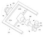
도 5는 본 발명의 실시예에 따른 측정된 수치정보데이터를 처리하는 3차원 공간영상도화시스템을 구성하는 드론의 구성을 나타낸 사시도이다.
도 6은 본 발명의 실시예에 따른 드론의 카메라부가 설치된 모습을 나타낸 도면이다.
도 7은 본 발명의 실시예에 따른 드론의 카메라부의 수평 유지 각도를 조절하는 모습을 나타낸 도면이다.
그리고
도 8은 본 발명의 실시예에 따른 드론의 충격흡수부재의 단면을 나타낸 도면이다.BRIEF DESCRIPTION OF THE DRAWINGS Fig. 1 is a diagram showing a schematic image according to the prior art; Fig.
FIG. 2 is a diagram schematically illustrating a configuration of a three-dimensional spatial image display system for processing measured numerical information data according to an embodiment of the present invention.
3 is a view showing an example of a vehicle constituting a three-dimensional spatial imaging system for processing measured numerical information data according to an embodiment of the present invention.
4 is a view showing an operation example of an operation unit constituting a three-dimensional spatial image display system for processing measured numerical information data according to an embodiment of the present invention.
FIG. 5 is a perspective view showing the configuration of a dron constituting a three-dimensional spatial image display system for processing measured numerical information data according to an embodiment of the present invention.
6 is a view illustrating a state in which a drones are installed in a camera unit according to an embodiment of the present invention.
7 is a view showing a state in which the horizontal holding angle of the camera unit of the drones is adjusted according to the embodiment of the present invention.
And
8 is a cross-sectional view of an impact absorbing member of a drone according to an embodiment of the present invention.
아래에서는 첨부한 도면을 참고로 하여 본 발명의 실시예에 대하여 본 발명이 속하는 기술 분야에서 통상의 지식을 가진 자가 용이하게 실시할 수 있도록 상세히 설명한다. 그러나 본 발명은 여러 가지 상이한 형태로 구현될 수 있으며 여기에서 설명하는 실시예에 한정되지 않는다. 그리고 도면에서 본 발명을 명확하게 설명하기 위해서 설명과 관계없는 부분은 생략하였으며, 명세서 전체를 통하여 유사한 부분에 대해서는 유사한 도면 부호를 붙였다.Hereinafter, embodiments of the present invention will be described in detail with reference to the accompanying drawings so that those skilled in the art can easily carry out the present invention. The present invention may, however, be embodied in many different forms and should not be construed as limited to the embodiments set forth herein. In order to clearly illustrate the present invention, parts not related to the description are omitted, and similar parts are denoted by like reference characters throughout the specification.
명세서 전체에서, 어떤 부분이 어떤 구성요소를 "포함"한다고 할 때, 이는 특별히 반대되는 기재가 없는 한 다른 구성요소를 제외하는 것이 아니라 다른 구성요소를 더 포함할 수 있는 것을 의미한다.Throughout the specification, when an element is referred to as "comprising ", it means that it can include other elements as well, without excluding other elements unless specifically stated otherwise.
종래의 공간영상도화시스템에서의 항공 촬영은 비용이 많이 들기 때문에 주기적으로 반복해서 자주 촬영할 수 없어 수시로 변화되는 지형지물의 형상 특성을 신속하게 반영하기 어려우며, 항공 촬영 시 카메라는 수평 자세를 유지하기 어려우며, 지상물을 여러 각도와 방향으로 촬영해야 하므로 카메라의 자유로운 각도 조절이나 이동이 어려운 문제점이 있다.Since the aerial photographing in the conventional spatial image visualization system is costly, it is difficult to repeatedly photograph frequently and repeatedly so that it is difficult to quickly reflect the shape characteristics of the landform which changes frequently, and it is difficult to maintain the horizontal posture in the aerial photographing, There is a problem that it is difficult to adjust the angle of the camera or to move the camera freely.
본 발명은 항공촬영 시 비행기를 이용하는 대신에 주기적인 촬영이 가능한 드론을 이용하고 여러 가지 촬영 각도에서도 수평을 유지하거나 원하는 촬영 각도를 조정하여 정확하고 신뢰도 있는 도화이미지를 완성하는 측정된 수치정보데이터를 처리하는 3차원 공간영상도화시스템을 제공한다.The present invention relates to a method and an apparatus for measuring numerical information data, which uses a drone capable of periodic photographing instead of using an airplane in aerial photographing, and maintains a horizontal angle at various photographing angles or adjusts a desired photographing angle, Dimensional spatial image display system.
도 2는 본 발명의 실시예에 따른 측정된 수치정보데이터를 처리하는 3차원 공간영상도화시스템의 구성을 간략하게 나타낸 도면이고, 도 3은 본 발명의 실시예에 따른 측정된 수치정보데이터를 처리하는 3차원 공간영상도화시스템을 구성하는 차량의 일례를 나타낸 도면이고, 도 4는 본 발명의 실시예에 따른 측정된 수치정보데이터를 처리하는 3차원 공간영상도화시스템을 구성하는 연산부의 연산례를 나타낸 도면이다.FIG. 2 is a simplified view of the configuration of a three-dimensional spatial imaging system for processing measured numerical information data according to an embodiment of the present invention. FIG. 3 is a block diagram of a three- FIG. 4 is a view showing an example of an operation of a calculation unit constituting a three-dimensional spatial image drawing system for processing measured numerical information data according to an embodiment of the present invention. Fig.
본 발명의 실시예에 따른 3차원 공간영상도화시스템은 좌표기준점 기능을 수행하도록 RF 발신기(R1,R2,R3)와 GPS 수신기(G1,G2,G3)를 탑재한 적어도 3대의 이동가능한 차량(100,102,104)과, 상기 RF 발신기(R1,R2,R3)로부터 수신된 RF를 통해 각 RF 발신기(R1,R2,R3)를 식별하고, GPS 수신기(G1,G2,G3)로부터 수신된 좌표정보를 촬영존에 맞춰 RF 발신기(R1,R2,R3) 별로 코딩한 촬영이미지를 생성하는 드론(200)과, 상기 드론(200)이 생성한 촬영이미지를 수신하여 도화를 수행하는 도화모듈(330)을 구비한 관리서버(300)를 포함한다.The three-dimensional spatial image-drawing system according to the embodiment of the present invention includes at least three
이때, 상기 차량(100,102,104)은 도 3에 도시된 바와 같이, 메모리가 실장된 차량제어기(110)를 포함하며, 상기 차량제어기(110)의 제어신호에 따라 RF를 발신하는 RF 발신기(R1,R2,R2)가 각 차량에 하나씩 설치된다.3, the
또한, 상기 차량(100,102,104)에는 상기 차량제어기(110)의 제어신호에 위성과 통신하여 위치정보, 즉 좌표정보를 확인하는 GPS 수신기(G1,G2,G3)도 구비된다.The
차량(100,102,104)의 지붕에는 차량용 스테레오카메라(120)가 더 설치되어 입체 영상이미지를 촬영할 수 있도록 구비되는데, 이는 높이가 높은 건물의 경우 그 직상방에서 드론(200)이 촬영할 경우 측면 이미지가 제대로 나타나지 않을 수 있으므로 측면 이미지를 입체 영상이미지로 획득한 후 평면 이미지와 합성함으로써 전체적인 외관이미지를 3차원 입체 이미지로 변환시킬 수 있다.A
RF 발신기(R1,R2,R3)는 RF를 발진시켜 드론(200)이 수신할 수 있도록 하는 것으로, 발진된 신호는 RF 발신기(R1,R2,R3) 별로 서로 다른 주파수 대역을 갖는 고유한 RF를 포함한다.RF oscillators R1, R2 and R3 oscillate RF so that the
드론(200)은 수신한 RF를 통해 당해 RF를 발진한 RF 발신기(R1,R2,R3)를 식별할 수 있다.The
RF 발신기(R1,R2,R3)는 드론(200)이 촬영대상 지면(즉, 촬영존)에 진입하면 각 차량(100,102,104)에 설치된 차량제어기(110)에 의해 각각 제어되어 단발 또는 일정 간격을 두고 연발로 지속해서 발신하도록 제어될 수 있다The RF transmitters R1, R2 and R3 are controlled by the
한편, 상기 드론(200)은 관리서버(300) 및 차량(100,102,104)과의 무선통신을 비롯한 기능 구현에 필요한 제어를 위해 제어부(210)를 탑재한다.Meanwhile, the
상기 제어부(210)는 촬영존의 촬영을 위한 카메라부(253)와, RF 발신기(R1,R2,R3)로부터 발신된 신호를 수신하는 RF 수신부(212)와, 드론(200)이 위치한 고도를 측정하는 고도계(213)와, 위성과의 통신을 통해 드론(200)이 현재 위치한 지점의 지피에스 좌표를 확인하는 좌표계(214)와, RF 수신부(212)가 수신한 위치정보와 좌표계(214)가 확인한 위치정보 및 고도계(213)에서 확인된 고도정보를 이용하여 각 RF 발신기(R1,R2,R3)까지의 지면상 거리를 산출하는 연산부(215)와, 상기 연산부(215)가 연산한 거리정보와 RF 수신기(212)가 수신한 위치정보를 확인하여 촬영존의 촬영이미지 상에 위치정보를 합성하는 위치정보합성부(216)와, 합성된 영상이미지를 저장하는 저장부(217)를 포함한다.The
이때, 상기 카메라부(253)은 촬영존의 촬영을 위한 일반적인 카메라로, 아날로그 방식 또는 디지털 방식이 적용될 수 있지만, 특히 바람직하기로는 입체영상 이미지 확보를 위해 드론용 스테레오카메라를 사용한다.At this time, the
그리고 상기 RF 수신부(212)는 RF 발신기(R1,R2,R3)가 발신한 서로 다른 주파수 대역에 대응하여 발진 신호에 포함된 RF를 확인하여 구별하며, 구별 정보는 제어부(210)가 인식한다.The
상기 연산부(215)는 도 4에 도시된 바와 같이, 촬영존의 둘레 중 적어도 3곳에 배치된 RF 발신기(R1,R2,R3)와 GPS 수신기(G1,G2,G3)를 탑재한 차량(100,102,104)과, 촬영존 내의 상부 일정 높이에서 호버링하고 있는 드론(200)이 제공하는 정보를 통해 촬영존, 즉 드론(200)에 장착된 카메라부(253)가 한번에 촬영할 수 있는 단위 공간의 크기에 대한 영상이미지에 좌표값, 다시 말해 위치정보를 삽입하여 도화모듈(330)이 도화할 때 정확한 도화가 가능하도록 차량(100,102,104)의 위치정보를 정확히 하기 위해 드론(200)을 기준으로 얼마만큼 떨어져 있는지를 계산하기 위한 것이다. 드론(200)의 위치는 좌표계(214)를 통해 알고 있다.As shown in FIG. 4, the
또한, 촬영존의 드론(200) 직하방 지면 지점은 고도계(213)를 통해 알고 있다. 각 RF발신기(R1,R2,R3)까지의 거리는 RF의 속도와 RF 수신부(212)가 수신한 시간을 통해 알 수 있다. 촬영존 내의 드론(200) 직하방 지면 지점으로부터 각 RF 발신기(R1,R2,R3)까지의 거리는 직각 삼각형을 형성하므로 피타고라스의 정리에 의해 산출되게 된다.Further, a point directly below the
이렇게, 촬영존 내의 드론(200) 직하방 지면 지점을 기준으로 각 GPS 수신기(G1,G2,G3)가 획득한 좌표값과, 기준점으로부터 RF 발신기(R1,R2,R3)까지의 거리정보를 알기 때문에 결국 촬영된 촬영존의 영상이미지에 RF 발신기(R1,R2,R3)의 위치정보를 표시할 수 있고, 이를 통해 촬영존의 영상이미지를 도화할 때 각 위치정보를 기반으로 도화하게 되면 정확한 도화가 가능하게 된다.In this way, the coordinate values obtained by the GPS receivers G1, G2, and G3 and the distance information from the reference point to the RF transmitters R1, R2, and R3 are obtained based on the points immediately below the
그리고 상기 저장부(217)는 위치정보가 합성된 촬영이미지를 저장물 형태로 기록한 후 제어부(210)의 제어 신호에 따라 도화모듈(330)로 전송하게 된다.The
한편, 상기 드론(200)은 장시간, 이를 테면 적어도 6시간 이상 비행할 수 있도록 부력상승 기능을 갖는 구조로 이루어진다.On the other hand, the
도 5는 본 발명의 실시예에 따른 측정된 수치정보데이터를 처리하는 3차원 공간영상도화시스템을 구성하는 드론의 구성을 나타낸 사시도이고, 도 6은 본 발명의 실시예에 따른 드론의 카메라부가 설치된 모습을 나타낸 도면이고, 도 7은 본 발명의 실시예에 따른 드론의 카메라부의 수평 유지 각도를 조절하는 모습을 나타낸 도면이고, 도 8은 본 발명의 실시예에 따른 드론의 충격흡수부재의 단면을 나타낸 도면이다.FIG. 5 is a perspective view illustrating a configuration of a dron constituting a three-dimensional spatial image display system for processing measured numerical information data according to an embodiment of the present invention. 7 is a view illustrating a state in which the horizontal holding angle of the camera unit of the dron according to the embodiment of the present invention is adjusted, and FIG. 8 is a cross- sectional view of the impact absorbing member of the dron according to the embodiment of the present invention. Fig.
본 발명의 실시예에 따른 드론(200)은 육면체 형태의 드론제어본체(201)와, 상기 드론제어본체(201)에 결합된 복수의 프로펠러(202, 203, 204, 205)와, 상기 드론제어본체(201)의 하부에 결합된 드론몸체(220)를 포함한다.A
드론제어본체(201)와 드론모터부(202a, 203a, 204a, 205a)는 가볍고 내구성이 좋은 알루미늄 합금강으로 제조하고, 드론모터부(202a, 203a, 204a, 205a)의 상부면에 프로펠러(202, 203, 204, 205)가 각각 장착된다.The
프로펠러(202, 203, 204, 205)는 일정 형상의 프로펠러를 포함할 수 있으며, 프로펠러(202, 203, 204, 205)의 동작에 의해서 아래 방향으로의 기류가 발생되게 되며, 이로 인해 드론(100)이 비행할 수 있도록 하는 양력이 발생하게 된다.The
드론모터부(202a, 203a, 204a, 205a)는 비행로봇 제어부(미도시)의 자세제어와 위치제어에 따라 호버링, 추력, 롤운동, 피치운동을 하면서 특정 위치까지 공중 부양되어 드론제어본체(201)를 정위치시키는 역할을 한다 이외에 드론(200)은 종래 기술의 비행로봇으로 비행에 필요한 드론암, 드론로터, 드론로터모터 등의 상세 구성요소의 설명을 생략한다.The
드론몸체(220)는 원호 형태로 형성되어 드론(200)이 비행, 착륙 등을 수행할 때 드론제어본체(201)를 보호하도록 구성된다.The
드론몸체(220)는 일측 끝단과 타측 끝단에 직각 방향으로 제1 지지봉(221a)와 제2 지지봉(221b)을 결합한다.The
드론몸체(220)는 하면 테두리를 따라 제1 랙기어(222)가 형성되고, 상기 제1 랙기어(222)에 기어 맞물려 결합되는 제1 피니언 기어(223)를 구비한 육면체 형태의 제1 하우징(225)을 포함한다.The
제1 하우징(225)의 내부에는 제1 피니언 기어(223)에 제1 구동모터(224)가 결합되어 제1 피니언 기어(223)의 구동력을 제공한다.A
제1 하우징(225)의 하부면에는 하부 방향으로 일정한 길이의 제2 랙기어(230)가 수직 세워진다.On the lower surface of the
제1 구동모터(224)가 구동되면, 제1 피니언 기어(223)가 회전하고, 이에 따라 제1 하우징(225)은 제1 피니언기어(223)에 맞물려 있는 제1 랙기어(222)를 따라 원호 방향으로 좌우 이동된다.When the
상기 제2 랙기어(230)는 제2 피니언 기어(232)가 기어 맞물려 결합되고, 상기 제2 피니언 기어(232)가 포함된 육면체 형태의 제2 하우징(234)을 상하 방향으로 관통하여 결합된다.The
제2 하우징(234)의 내부에는 제2 피니언 기어(232)에 제2 구동모터(233)가 결합되어 제2 피니언 기어(232)의 구동력을 제공한다.A
제2 구동모터(233)가 구동되면, 제2 피니언 기어(232)가 회전하고, 이에 따라 제2 하우징(234)은 제2 피니언기어(232)에 맞물려 있는 제2 랙기어(230)를 따라 상하 방향으로 이동된다.When the
제2 하우징(234)은 일측면에 제1 회전모터(235)와 제1 회전대(236)가 일체로 결합되고, 'ㄷ' 형태로 절곡된 제1 거치대(237a)와 제2 거치대(237b)를 구비한 거치대(237)가 제1 회전대(236)에 결합된다.The
제1 거치대(237a)와 제2 거치대(237b)의 사이에는 길이 방향의 볼스크루부재(238)가 결합되고, 상기 볼스크류부재(238)는 일측 끝단이 제2 거치대(237b)를 관통하여 제2 구동모터(238a)가 결합된다.A
이동블록부(239)는 육면체 형상으로 중심 부분을 상기 볼스크류부재(238)가 관통되어 결합되고, 볼스크류부재(238)의 외주면 나사산에 각각 맞물리는 나사선을 내측면에 형성하고 있다.The
이동블록부(239)는 제2 구동모터(238a)의 구동력에 의해 볼스크류부재(238)의 회전에 따라 볼스크류부재(238)의 축방향으로 직선 이동하게 된다.The moving
이동블록부(239)의 상부면에는 충격을 흡수하거나 저감시키는 충격흡수부재(240)를 수직으로 세워져 결합된다.On the upper surface of the
충격흡수부재(240)는 상부면에 제2 회전모터(250)가 결합되고, 상기 제2 회전모터(250)의 전면에 'ㄴ' 형태의 제2 회전대(252)가 결합된다.The
상기 제2 회전대(252)에는 카메라부(253)가 탑재되어 항공사진을 촬영한다.A
충격흡수부재(240)는 제2 회전모터(250)의 하부면에 원통 형상으로 일정한 길이의 제1 원통로드(241)가 결합되고, 상기 제1 원통로드(241)의 하부 일부가 관통되도록 내부의 일정 공간부를 구비한 제1 케이스(243)가 형성된다.The
제1 케이스(243)의 내부에는 상기 제1 원통로드(241)의 하부 끝단에 수직 방향으로 결합된 제1 피스톤(242)과, 상기 제1 피스톤(242)의 하부면과 제1 케이스의(243)의 바닥면 사이에 제1 스프링부재(244)가 결합되며, 제1 케이스(243)의 내부 공간에 충격을 흡수하는 제1 충격완충물질(245)이 충진되어 채워져 있다.A
제1 피스톤(242)의 하부면에는 제2 원통로드(241a)가 수직으로 세워져 결합되고, 상기 제2 원통로드(241a)의 하부 일부가 관통되도록 내부의 일정 공간부를 구비한 제2 케이스(247)가 형성된다.A second cylindrical rod 241a is vertically coupled to the lower surface of the
제2 케이스(247)의 내부에는 상기 제2 원통로드(241a)의 하부 끝단에 수직 방향으로 결합된 제2 피스톤(246)과, 상기 제2 피스톤(246)의 하부면과 제2 케이스의(247)의 바닥면 사이에 제2 스프링부재(248)가 결합되며, 제2 케이스(247)의 내부 공간에 충격을 흡수하는 제2 충격완충물질(249)이 충진되어 채워져 있다.A
제어부(210)는 제1 구동모터(224)를 구동시켜 제1 하우징(225)의 제1 피니언기어(223)를 회전시켜 제1 하우징(225)이 제1 랙기어(222)를 따라 곡선 방향으로 이동된다.The
제어부(210)는 제2 구동모터(233)를 구동시켜 제2 하우징(234)의 제2 피니언기어(232)를 회전시켜 제2 하우징(234)이 제2 랙기어(230)를 따라 상하 방향으로 이동된다.The
제어부(210)는 기울기센서(218)로부터 드론제어본체(201)의 기울어진 각도 정보를 수신하는 경우, 상기 수신한 각도 정보를 기준으로 카메라부(253)의 수평 유지 각도를 계산하며, 계산된 수평 유지 각도를 제1 회전모터(235), 제2 회전모터(250) 중 하나 또는 모두를 제어하여 구현한다.The
제어부(210)는 제1 회전모터(235)를 구동시켜 제1 회전대(236)를 일정 각도로 회전시키거나, 제2 구동모터(238a)를 구동시켜 볼스크류부재(238)의 회전에 따라 이동블록부(239)를 볼스크류부재(238)의 축방향으로 직선 이동하거나, 제2 회전모터(250)를 구동시켜 제2 회전대(252)를 일정 각도로 회전시키는 등 필요에 따라 카메라부(253)의 촬영 위치를 다양하게 설정할 수 있다.The
이상에서 설명한 본 발명의 실시예는 장치 및/또는 방법을 통해서만 구현이 되는 것은 아니며, 본 발명의 실시예의 구성에 대응하는 기능을 실현하기 위한 프로그램, 그 프로그램이 기록된 기록 매체 등을 통해 구현될 수도 있으며, 이러한 구현은 앞서 설명한 실시예의 기재로부터 본 발명이 속하는 기술분야의 전문가라면 쉽게 구현할 수 있는 것이다.The embodiments of the present invention described above are not implemented only by the apparatus and / or method, but may be implemented through a program for realizing functions corresponding to the configuration of the embodiment of the present invention, a recording medium on which the program is recorded And such an embodiment can be easily implemented by those skilled in the art from the description of the embodiments described above.
이상에서 본 발명의 실시예에 대하여 상세하게 설명하였지만 본 발명의 권리범위는 이에 한정되는 것은 아니고 다음의 청구범위에서 정의하고 있는 본 발명의 기본 개념을 이용한 당업자의 여러 변형 및 개량 형태 또한 본 발명의 권리범위에 속하는 것이다.While the present invention has been particularly shown and described with reference to exemplary embodiments thereof, it is to be understood that the invention is not limited to the disclosed exemplary embodiments, It belongs to the scope of right.
100, 102, 104: 차량110: 차량제어기
200: 드론201: 드론제어본체
202, 203, 204, 205: 프로펠러300: 관리서버
202a, 203a, 204a, 205a: 드론모터부100, 102, 104: vehicle 110: vehicle controller
200: Drone 201: Drone control body
202, 203, 204, 205: propeller 300: management server
202a, 203a, 204a, and 205a:
Claims (1)
Translated fromKorean상기 차량(100,102,104)은 메모리가 실장된 차량제어기(110)를 포함하며, 상기 차량제어기(110)의 제어신호에 따라 RF를 발신하는 RF 발신기(R1,R2,R2)가 각 차량에 하나씩 설치되고, 상기 차량(100,102,104) 각각에는 상기 차량제어기(110)의 제어신호하에 위성과 통신하여 차량(100,102,104)의 각 제1 위치정보를 확인하는 GPS 수신기(G1,G2,G3)를 구비하며,
상기 드론(200)은 상기 관리서버(300) 및 상기 차량(100,102,104)과의 무선통신을 제어하는 제어부(210)를 탑재하며,
상기 제어부(210)는 촬영존의 촬영을 위한 카메라부(253)와, RF 발신기(R1,R2,R3)로부터 발신된 신호를 수신하는 RF 수신부(212)와, 드론(200)이 위치한 고도를 측정하는 고도계(213)와, 위성과의 통신을 통해 드론(200)이 현재 위치한 지점의 지피에스 좌표를 확인하는 좌표계(214)와, RF 수신부(212)가 수신한 RF 신호와 좌표계(214)가 확인한 제2 위치정보 및 고도계(213)에서 확인된 고도정보를 이용하여 각 RF 발신기(R1,R2,R3)까지의 지면상 거리를 산출하는 연산부(215)와, 상기 연산부(215)가 연산한 거리정보와 좌표계(214)가 확인한 제2 위치정보를 확인하여 촬영존의 촬영이미지 상에 상기 제2 위치정보를 합성하는 위치정보합성부(216)와, 합성된 영상이미지를 저장하는 저장부(217)를 포함하고,
상기 드론(200)은 육면체 형태의 드론제어본체(201)와, 상기 드론제어본체(201)에 결합된 복수의 프로펠러(202, 203, 204, 205)와, 상기 드론제어본체(201)의 하부에 결합되고, 드론몸체(220)의 하면 테두리를 따라 제1 랙기어(222)가 형성되고, 상기 제1 랙기어(222)에 기어 맞물려 결합되는 제1 피니언 기어(223)를 구비한 육면체 형태의 제1 하우징(225)을 구비한 원호 형태로 형성된 드론몸체(220)를 포함하며, 상기 제1 하우징(225)의 내부에는 제1 피니언 기어(223)에 제1 구동모터(224)가 결합되고, 상기 제1 하우징(225)의 하부면에 하부 방향으로 일정한 길이의 제2 랙기어(230)가 상기 제1 하우징(225)의 수평면을 기준으로 수직으로 세워지고,
상기 제2 랙기어(230)는 제2 피니언 기어(232)가 기어 맞물려 결합되고, 상기 제2 피니언 기어(232)가 포함된 육면체 형태의 제2 하우징(234)을 상하 방향으로 관통하여 결합되고, 상기 제2 하우징(234)의 내부에는 제2 피니언 기어(232)에 제2 구동모터(233)가 결합되고,
상기 제2 하우징(234)은 일측면에 제1 회전모터(235)와 제1 회전대(236)가 일체로 결합되고, 'ㄷ' 형태로 절곡된 제1 거치대(237a)와 제2 거치대(237b)를 구비한 거치대(237)가 제1 회전대(236)에 결합되며, 상기 거치대(237)의 일측에 상기 카메라부(253)가 결합되며,
상기 제어부(210)는 상기 제1 구동모터(224)을 구동시켜 상기 제1 하우징(225)이 상기 제1 랙기어(222)을 따라 원호 방향으로 좌우 이동하고, 상기 제2 구동모터(233)을 구동시켜 상기 제2 하우징(234)이 상기 제2 랙기어(230)를 따라 상하 방향으로 이동하며, 상기 제1 회전모터(235)를 구동시켜 상기 카메라부(253)를 회전시키는 것을 특징으로 하는 측정된 수치정보데이터를 처리하는 3차원 공간영상도화시스템.
At least three movable vehicles 100, 102, 104 mounted with RF transmitters R1, R2, R3 and GPS receivers G1, G2, G3 to perform a coordinate reference point function; R2, and R3 by using the received RF, and the coordinate information received from the GPS receivers (G1, G2, G3) is coded for each of the RF transmitters (R1, R2, R3) 1. A spatial image drawing system comprising a drones (200) for generating images, and a management server (300) for receiving the photographed images generated by the drones (200) and performing drawing,
Each of the vehicles 100, 102 and 104 includes a vehicle controller 110 in which a memory is mounted and RF transmitters R1, R2 and R2 which emit RF according to a control signal of the vehicle controller 110 are installed one by one in each vehicle And GPS receivers G1, G2 and G3 for communicating with the satellites under the control signal of the vehicle controller 110 to confirm respective first position information of the vehicles 100, 102 and 104,
The dron 200 is equipped with a control unit 210 for controlling wireless communication with the management server 300 and the vehicles 100, 102 and 104,
The control unit 210 includes a camera unit 253 for capturing an image capturing zone, an RF receiving unit 212 for receiving signals transmitted from the RF transmitters R1, R2 and R3, A coordinate system 214 for confirming the geoS coordinates of the point at which the drone 200 is currently located through communication with the satellite and an RF signal received by the RF receiving unit 212 and a coordinate system 214 An arithmetic operation unit 215 for calculating a distance on the ground to each of the RF transmitters R1, R2 and R3 using the verified second position information and the altitude information confirmed by the altimeter 213; A position information synthesizing unit 216 for synthesizing the second position information on the photographed image of the photographing zone by confirming the distance information and the second position information confirmed by the coordinate system 214 and a storage unit 217)
The dron 200 comprises a hexahedral dron control body 201, a plurality of propellers 202, 203, 204, 205 coupled to the dron control body 201, A first rack gear 222 is formed along the bottom edge of the drone body 220 and a first pinion gear 223 is coupled to the first rack gear 222 in a gear- And a first driving motor 224 is coupled to the first pinion gear 223 within the first housing 225. The first housing 225 is coupled to the first housing 225, A second rack gear 230 having a predetermined length in a downward direction is vertically erected on a horizontal plane of the first housing 225 on the lower surface of the first housing 225,
The second rack gear 230 is engaged with the second pinion gear 232 in a gear engagement manner and vertically penetrates the second housing 234 having a hexahedral shape including the second pinion gear 232 A second drive motor 233 is coupled to the second pinion gear 232 in the second housing 234,
The second housing 234 is integrally formed with a first rotation motor 235 and a first rotation table 236 on one side thereof and includes a first cradle 237a and a second cradle 237b And the camera unit 253 is coupled to one side of the cradle 237. The camera unit 253 is coupled to the first cradle 236,
The controller 210 drives the first driving motor 224 so that the first housing 225 moves left and right in the circular arc direction along the first rack gear 222, The second housing 234 moves up and down along the second rack gear 230 and drives the first rotation motor 235 to rotate the camera unit 253. [ Dimensional spatial image display system for processing the measured numerical information data.
Priority Applications (1)
| Application Number | Priority Date | Filing Date | Title |
|---|---|---|---|
| KR1020180050667AKR101893078B1 (en) | 2018-05-02 | 2018-05-02 | 3D Image Drawing System for Processing Measured Numerical Data |
Applications Claiming Priority (1)
| Application Number | Priority Date | Filing Date | Title |
|---|---|---|---|
| KR1020180050667AKR101893078B1 (en) | 2018-05-02 | 2018-05-02 | 3D Image Drawing System for Processing Measured Numerical Data |
Publications (1)
| Publication Number | Publication Date |
|---|---|
| KR101893078B1true KR101893078B1 (en) | 2018-08-29 |
Family
ID=63434813
Family Applications (1)
| Application Number | Title | Priority Date | Filing Date |
|---|---|---|---|
| KR1020180050667AActiveKR101893078B1 (en) | 2018-05-02 | 2018-05-02 | 3D Image Drawing System for Processing Measured Numerical Data |
Country Status (1)
| Country | Link |
|---|---|
| KR (1) | KR101893078B1 (en) |
Cited By (7)
| Publication number | Priority date | Publication date | Assignee | Title |
|---|---|---|---|---|
| KR102101333B1 (en)* | 2019-12-30 | 2020-04-17 | (주)지오투정보기술 | Image processing system to improve the accuracy of captured images |
| KR20200059443A (en) | 2018-11-21 | 2020-05-29 | 한국항공우주연구원 | Method and system for acquiring 3-D shape information of target object |
| KR102182341B1 (en)* | 2020-05-11 | 2020-11-24 | (주)스페이스 | Spatial imaging system with upgraded aerial photography |
| KR102332300B1 (en) | 2021-05-10 | 2021-12-01 | 육지영 | Electric pole for extra-high voltage distribution line |
| KR102391362B1 (en)* | 2021-10-20 | 2022-04-26 | 강병삼 | An apparatus of protection transmission tower |
| KR20220128213A (en)* | 2021-03-12 | 2022-09-20 | 주식회사 에이엔에이치시스템즈 | Bundle type dropping equipment for a drone |
| KR20240116130A (en)* | 2023-01-20 | 2024-07-29 | 지오랩스(주) | Photoflight system for maintaining vertical direction of camera |
Citations (8)
| Publication number | Priority date | Publication date | Assignee | Title |
|---|---|---|---|---|
| KR101018078B1 (en) | 2010-10-01 | 2011-03-02 | 주식회사 우리강산시스템 | Image Mapping Synthesis System for Drawing Image Images of Features |
| KR101545665B1 (en)* | 2014-07-29 | 2015-08-24 | 한국종합설계 주식회사 | Image Expression Mapping System Using Space Image and Numeric Information |
| JP2016501161A (en)* | 2012-12-14 | 2016-01-18 | カレカー、レイモンド ジョージCARREKER,Raymond George | Direct stereo vector rotor (DOVER) |
| US9630713B1 (en)* | 2015-12-17 | 2017-04-25 | Qualcomm Incorporated | Unmanned aerial vehicle with adjustable aiming component |
| KR101815260B1 (en)* | 2017-10-13 | 2018-01-30 | (주)태영정보시스템 | Spatial image-drawing system applying reference point location and topographic information |
| KR101845887B1 (en)* | 2018-02-23 | 2018-04-06 | 중앙항업(주) | Spatial image drawing system of video image by reference point of feature |
| KR101846519B1 (en)* | 2017-10-30 | 2018-04-09 | (주)국토해양기술 | Compensation System for Spatial Image Dissipation of Setting the base point of the feature |
| KR101835516B1 (en)* | 2017-10-12 | 2018-04-19 | 주식회사 유성 | A spatial image-drawing system for visualizing image by feature |
- 2018
- 2018-05-02KRKR1020180050667Apatent/KR101893078B1/enactiveActive
Patent Citations (8)
| Publication number | Priority date | Publication date | Assignee | Title |
|---|---|---|---|---|
| KR101018078B1 (en) | 2010-10-01 | 2011-03-02 | 주식회사 우리강산시스템 | Image Mapping Synthesis System for Drawing Image Images of Features |
| JP2016501161A (en)* | 2012-12-14 | 2016-01-18 | カレカー、レイモンド ジョージCARREKER,Raymond George | Direct stereo vector rotor (DOVER) |
| KR101545665B1 (en)* | 2014-07-29 | 2015-08-24 | 한국종합설계 주식회사 | Image Expression Mapping System Using Space Image and Numeric Information |
| US9630713B1 (en)* | 2015-12-17 | 2017-04-25 | Qualcomm Incorporated | Unmanned aerial vehicle with adjustable aiming component |
| KR101835516B1 (en)* | 2017-10-12 | 2018-04-19 | 주식회사 유성 | A spatial image-drawing system for visualizing image by feature |
| KR101815260B1 (en)* | 2017-10-13 | 2018-01-30 | (주)태영정보시스템 | Spatial image-drawing system applying reference point location and topographic information |
| KR101846519B1 (en)* | 2017-10-30 | 2018-04-09 | (주)국토해양기술 | Compensation System for Spatial Image Dissipation of Setting the base point of the feature |
| KR101845887B1 (en)* | 2018-02-23 | 2018-04-06 | 중앙항업(주) | Spatial image drawing system of video image by reference point of feature |
Cited By (9)
| Publication number | Priority date | Publication date | Assignee | Title |
|---|---|---|---|---|
| KR20200059443A (en) | 2018-11-21 | 2020-05-29 | 한국항공우주연구원 | Method and system for acquiring 3-D shape information of target object |
| KR102101333B1 (en)* | 2019-12-30 | 2020-04-17 | (주)지오투정보기술 | Image processing system to improve the accuracy of captured images |
| KR102182341B1 (en)* | 2020-05-11 | 2020-11-24 | (주)스페이스 | Spatial imaging system with upgraded aerial photography |
| KR20220128213A (en)* | 2021-03-12 | 2022-09-20 | 주식회사 에이엔에이치시스템즈 | Bundle type dropping equipment for a drone |
| KR102537597B1 (en)* | 2021-03-12 | 2023-05-26 | 주식회사 에이엔에이치시스템즈 | Bundle type dropping equipment for a drone |
| KR102332300B1 (en) | 2021-05-10 | 2021-12-01 | 육지영 | Electric pole for extra-high voltage distribution line |
| KR102391362B1 (en)* | 2021-10-20 | 2022-04-26 | 강병삼 | An apparatus of protection transmission tower |
| KR20240116130A (en)* | 2023-01-20 | 2024-07-29 | 지오랩스(주) | Photoflight system for maintaining vertical direction of camera |
| KR102731372B1 (en) | 2023-01-20 | 2024-11-18 | 지오랩스(주) | Photoflight system for maintaining vertical direction of camera |
Similar Documents
| Publication | Publication Date | Title |
|---|---|---|
| KR101893078B1 (en) | 3D Image Drawing System for Processing Measured Numerical Data | |
| US11914369B2 (en) | Multi-sensor environmental mapping | |
| US11949992B2 (en) | UAV panoramic imaging | |
| AU2018355491B2 (en) | Method for configuring navigation chart, obstacle avoidance method and device, terminal, unmanned aerial vehicle | |
| US10447912B2 (en) | Systems, methods, and devices for setting camera parameters | |
| EP2772725B1 (en) | Aerial Photographing System | |
| US11310412B2 (en) | Autofocusing camera and systems | |
| KR102174827B1 (en) | Photoflight system for acquiring precise image using gps and ins | |
| WO2017131838A2 (en) | Sonar sensor fusion and model based virtual and augmented reality systems and methods | |
| KR101835516B1 (en) | A spatial image-drawing system for visualizing image by feature | |
| US10983535B2 (en) | System and method for positioning a movable object | |
| JP6812667B2 (en) | Unmanned aerial vehicle control system, unmanned aerial vehicle control method and unmanned aerial vehicle | |
| KR101929846B1 (en) | Photoflight device for acquiring precise image using gps and ins | |
| WO2018146803A1 (en) | Position processing device, flight vehicle, position processing system, flight system, position processing method, flight control method, program, and recording medium | |
| CN113820709B (en) | Through-wall radar detection system and detection method based on unmanned aerial vehicle | |
| KR101815260B1 (en) | Spatial image-drawing system applying reference point location and topographic information | |
| JP2020191523A (en) | Unmanned mobile | |
| JP2021113005A (en) | Unmanned aerial vehicle system and flight control method | |
| KR101349148B1 (en) | Air shooting unit by using auto shooting system | |
| JP2010276772A (en) | Autonomous imaging device | |
| KR102584476B1 (en) | Photoflight device using gnss and ins | |
| KR102870149B1 (en) | Spatial image drawing system for improving drawing precision using drone and image | |
| JP2024074362A (en) | Unmanned Aerial Vehicle Landing System | |
| JP2024021143A (en) | 3D data generation system and 3D data generation method | |
| WO2023139628A1 (en) | Area setting system and area setting method |
Legal Events
| Date | Code | Title | Description |
|---|---|---|---|
| PA0109 | Patent application | St.27 status event code:A-0-1-A10-A12-nap-PA0109 | |
| PA0201 | Request for examination | St.27 status event code:A-1-2-D10-D11-exm-PA0201 | |
| PA0302 | Request for accelerated examination | St.27 status event code:A-1-2-D10-D17-exm-PA0302 St.27 status event code:A-1-2-D10-D16-exm-PA0302 | |
| PE0902 | Notice of grounds for rejection | St.27 status event code:A-1-2-D10-D21-exm-PE0902 | |
| P11-X000 | Amendment of application requested | St.27 status event code:A-2-2-P10-P11-nap-X000 | |
| P13-X000 | Application amended | St.27 status event code:A-2-2-P10-P13-nap-X000 | |
| E701 | Decision to grant or registration of patent right | ||
| PE0701 | Decision of registration | St.27 status event code:A-1-2-D10-D22-exm-PE0701 | |
| GRNT | Written decision to grant | ||
| PR0701 | Registration of establishment | St.27 status event code:A-2-4-F10-F11-exm-PR0701 | |
| PR1002 | Payment of registration fee | St.27 status event code:A-2-2-U10-U11-oth-PR1002 Fee payment year number:1 | |
| PG1601 | Publication of registration | St.27 status event code:A-4-4-Q10-Q13-nap-PG1601 | |
| PN2301 | Change of applicant | St.27 status event code:A-5-5-R10-R13-asn-PN2301 St.27 status event code:A-5-5-R10-R11-asn-PN2301 | |
| PR1001 | Payment of annual fee | St.27 status event code:A-4-4-U10-U11-oth-PR1001 Fee payment year number:4 | |
| P22-X000 | Classification modified | St.27 status event code:A-4-4-P10-P22-nap-X000 | |
| PR1001 | Payment of annual fee | St.27 status event code:A-4-4-U10-U11-oth-PR1001 Fee payment year number:5 | |
| PR1001 | Payment of annual fee | St.27 status event code:A-4-4-U10-U11-oth-PR1001 Fee payment year number:6 | |
| PR1001 | Payment of annual fee | St.27 status event code:A-4-4-U10-U11-oth-PR1001 Fee payment year number:7 | |
| R18-X000 | Changes to party contact information recorded | St.27 status event code:A-5-5-R10-R18-oth-X000 | |
| PR1001 | Payment of annual fee | St.27 status event code:A-4-4-U10-U11-oth-PR1001 Fee payment year number:8 |