KR101891902B1 - Reverse knee prosthesis - Google Patents
Reverse knee prosthesisDownload PDFInfo
- Publication number
- KR101891902B1 KR101891902B1KR1020167009291AKR20167009291AKR101891902B1KR 101891902 B1KR101891902 B1KR 101891902B1KR 1020167009291 AKR1020167009291 AKR 1020167009291AKR 20167009291 AKR20167009291 AKR 20167009291AKR 101891902 B1KR101891902 B1KR 101891902B1
- Authority
- KR
- South Korea
- Prior art keywords
- femoral
- knee
- pulley element
- lining
- cup
- Prior art date
- Legal status (The legal status is an assumption and is not a legal conclusion. Google has not performed a legal analysis and makes no representation as to the accuracy of the status listed.)
- Active
Links
Images


Classifications
- A—HUMAN NECESSITIES
- A61—MEDICAL OR VETERINARY SCIENCE; HYGIENE
- A61F—FILTERS IMPLANTABLE INTO BLOOD VESSELS; PROSTHESES; DEVICES PROVIDING PATENCY TO, OR PREVENTING COLLAPSING OF, TUBULAR STRUCTURES OF THE BODY, e.g. STENTS; ORTHOPAEDIC, NURSING OR CONTRACEPTIVE DEVICES; FOMENTATION; TREATMENT OR PROTECTION OF EYES OR EARS; BANDAGES, DRESSINGS OR ABSORBENT PADS; FIRST-AID KITS
- A61F2/00—Filters implantable into blood vessels; Prostheses, i.e. artificial substitutes or replacements for parts of the body; Appliances for connecting them with the body; Devices providing patency to, or preventing collapsing of, tubular structures of the body, e.g. stents
- A61F2/02—Prostheses implantable into the body
- A61F2/30—Joints
- A61F2/38—Joints for elbows or knees
- A61F2/3836—Special connection between upper and lower leg, e.g. constrained
- A61F2/3854—Special connection between upper and lower leg, e.g. constrained with ball and socket joint
- A—HUMAN NECESSITIES
- A61—MEDICAL OR VETERINARY SCIENCE; HYGIENE
- A61F—FILTERS IMPLANTABLE INTO BLOOD VESSELS; PROSTHESES; DEVICES PROVIDING PATENCY TO, OR PREVENTING COLLAPSING OF, TUBULAR STRUCTURES OF THE BODY, e.g. STENTS; ORTHOPAEDIC, NURSING OR CONTRACEPTIVE DEVICES; FOMENTATION; TREATMENT OR PROTECTION OF EYES OR EARS; BANDAGES, DRESSINGS OR ABSORBENT PADS; FIRST-AID KITS
- A61F2/00—Filters implantable into blood vessels; Prostheses, i.e. artificial substitutes or replacements for parts of the body; Appliances for connecting them with the body; Devices providing patency to, or preventing collapsing of, tubular structures of the body, e.g. stents
- A61F2/02—Prostheses implantable into the body
- A61F2/30—Joints
- A61F2/38—Joints for elbows or knees
- A61F2/3886—Joints for elbows or knees for stabilising knees against anterior or lateral dislocations
- A—HUMAN NECESSITIES
- A61—MEDICAL OR VETERINARY SCIENCE; HYGIENE
- A61L—METHODS OR APPARATUS FOR STERILISING MATERIALS OR OBJECTS IN GENERAL; DISINFECTION, STERILISATION OR DEODORISATION OF AIR; CHEMICAL ASPECTS OF BANDAGES, DRESSINGS, ABSORBENT PADS OR SURGICAL ARTICLES; MATERIALS FOR BANDAGES, DRESSINGS, ABSORBENT PADS OR SURGICAL ARTICLES
- A61L27/00—Materials for grafts or prostheses or for coating grafts or prostheses
- A61L27/14—Macromolecular materials
- A61L27/16—Macromolecular materials obtained by reactions only involving carbon-to-carbon unsaturated bonds
- A—HUMAN NECESSITIES
- A61—MEDICAL OR VETERINARY SCIENCE; HYGIENE
- A61F—FILTERS IMPLANTABLE INTO BLOOD VESSELS; PROSTHESES; DEVICES PROVIDING PATENCY TO, OR PREVENTING COLLAPSING OF, TUBULAR STRUCTURES OF THE BODY, e.g. STENTS; ORTHOPAEDIC, NURSING OR CONTRACEPTIVE DEVICES; FOMENTATION; TREATMENT OR PROTECTION OF EYES OR EARS; BANDAGES, DRESSINGS OR ABSORBENT PADS; FIRST-AID KITS
- A61F2/00—Filters implantable into blood vessels; Prostheses, i.e. artificial substitutes or replacements for parts of the body; Appliances for connecting them with the body; Devices providing patency to, or preventing collapsing of, tubular structures of the body, e.g. stents
- A61F2/02—Prostheses implantable into the body
- A61F2/30—Joints
- A61F2/46—Special tools for implanting artificial joints
- A61F2/4684—Trial or dummy prostheses
- A—HUMAN NECESSITIES
- A61—MEDICAL OR VETERINARY SCIENCE; HYGIENE
- A61F—FILTERS IMPLANTABLE INTO BLOOD VESSELS; PROSTHESES; DEVICES PROVIDING PATENCY TO, OR PREVENTING COLLAPSING OF, TUBULAR STRUCTURES OF THE BODY, e.g. STENTS; ORTHOPAEDIC, NURSING OR CONTRACEPTIVE DEVICES; FOMENTATION; TREATMENT OR PROTECTION OF EYES OR EARS; BANDAGES, DRESSINGS OR ABSORBENT PADS; FIRST-AID KITS
- A61F2/00—Filters implantable into blood vessels; Prostheses, i.e. artificial substitutes or replacements for parts of the body; Appliances for connecting them with the body; Devices providing patency to, or preventing collapsing of, tubular structures of the body, e.g. stents
- A61F2/02—Prostheses implantable into the body
- A61F2/30—Joints
- A61F2002/30001—Additional features of subject-matter classified in A61F2/28, A61F2/30 and subgroups thereof
- A61F2002/30108—Shapes
- A61F2002/30199—Three-dimensional shapes
- A61F2002/30301—Three-dimensional shapes saddle-shaped
- A—HUMAN NECESSITIES
- A61—MEDICAL OR VETERINARY SCIENCE; HYGIENE
- A61F—FILTERS IMPLANTABLE INTO BLOOD VESSELS; PROSTHESES; DEVICES PROVIDING PATENCY TO, OR PREVENTING COLLAPSING OF, TUBULAR STRUCTURES OF THE BODY, e.g. STENTS; ORTHOPAEDIC, NURSING OR CONTRACEPTIVE DEVICES; FOMENTATION; TREATMENT OR PROTECTION OF EYES OR EARS; BANDAGES, DRESSINGS OR ABSORBENT PADS; FIRST-AID KITS
- A61F2/00—Filters implantable into blood vessels; Prostheses, i.e. artificial substitutes or replacements for parts of the body; Appliances for connecting them with the body; Devices providing patency to, or preventing collapsing of, tubular structures of the body, e.g. stents
- A61F2/02—Prostheses implantable into the body
- A61F2/30—Joints
- A61F2002/30001—Additional features of subject-matter classified in A61F2/28, A61F2/30 and subgroups thereof
- A61F2002/30316—The prosthesis having different structural features at different locations within the same prosthesis; Connections between prosthetic parts; Special structural features of bone or joint prostheses not otherwise provided for
- A61F2002/30329—Connections or couplings between prosthetic parts, e.g. between modular parts; Connecting elements
- A61F2002/30331—Connections or couplings between prosthetic parts, e.g. between modular parts; Connecting elements made by longitudinally pushing a protrusion into a complementarily-shaped recess, e.g. held by friction fit
- A—HUMAN NECESSITIES
- A61—MEDICAL OR VETERINARY SCIENCE; HYGIENE
- A61F—FILTERS IMPLANTABLE INTO BLOOD VESSELS; PROSTHESES; DEVICES PROVIDING PATENCY TO, OR PREVENTING COLLAPSING OF, TUBULAR STRUCTURES OF THE BODY, e.g. STENTS; ORTHOPAEDIC, NURSING OR CONTRACEPTIVE DEVICES; FOMENTATION; TREATMENT OR PROTECTION OF EYES OR EARS; BANDAGES, DRESSINGS OR ABSORBENT PADS; FIRST-AID KITS
- A61F2/00—Filters implantable into blood vessels; Prostheses, i.e. artificial substitutes or replacements for parts of the body; Appliances for connecting them with the body; Devices providing patency to, or preventing collapsing of, tubular structures of the body, e.g. stents
- A61F2/02—Prostheses implantable into the body
- A61F2/30—Joints
- A61F2002/30001—Additional features of subject-matter classified in A61F2/28, A61F2/30 and subgroups thereof
- A61F2002/30316—The prosthesis having different structural features at different locations within the same prosthesis; Connections between prosthetic parts; Special structural features of bone or joint prostheses not otherwise provided for
- A61F2002/30329—Connections or couplings between prosthetic parts, e.g. between modular parts; Connecting elements
- A61F2002/30383—Connections or couplings between prosthetic parts, e.g. between modular parts; Connecting elements made by laterally inserting a protrusion, e.g. a rib into a complementarily-shaped groove
- A61F2002/30387—Dovetail connection
- A—HUMAN NECESSITIES
- A61—MEDICAL OR VETERINARY SCIENCE; HYGIENE
- A61F—FILTERS IMPLANTABLE INTO BLOOD VESSELS; PROSTHESES; DEVICES PROVIDING PATENCY TO, OR PREVENTING COLLAPSING OF, TUBULAR STRUCTURES OF THE BODY, e.g. STENTS; ORTHOPAEDIC, NURSING OR CONTRACEPTIVE DEVICES; FOMENTATION; TREATMENT OR PROTECTION OF EYES OR EARS; BANDAGES, DRESSINGS OR ABSORBENT PADS; FIRST-AID KITS
- A61F2/00—Filters implantable into blood vessels; Prostheses, i.e. artificial substitutes or replacements for parts of the body; Appliances for connecting them with the body; Devices providing patency to, or preventing collapsing of, tubular structures of the body, e.g. stents
- A61F2/02—Prostheses implantable into the body
- A61F2/30—Joints
- A61F2002/30001—Additional features of subject-matter classified in A61F2/28, A61F2/30 and subgroups thereof
- A61F2002/30316—The prosthesis having different structural features at different locations within the same prosthesis; Connections between prosthetic parts; Special structural features of bone or joint prostheses not otherwise provided for
- A61F2002/30329—Connections or couplings between prosthetic parts, e.g. between modular parts; Connecting elements
- A61F2002/30476—Connections or couplings between prosthetic parts, e.g. between modular parts; Connecting elements locked by an additional locking mechanism
- A61F2002/305—Snap connection
- A—HUMAN NECESSITIES
- A61—MEDICAL OR VETERINARY SCIENCE; HYGIENE
- A61F—FILTERS IMPLANTABLE INTO BLOOD VESSELS; PROSTHESES; DEVICES PROVIDING PATENCY TO, OR PREVENTING COLLAPSING OF, TUBULAR STRUCTURES OF THE BODY, e.g. STENTS; ORTHOPAEDIC, NURSING OR CONTRACEPTIVE DEVICES; FOMENTATION; TREATMENT OR PROTECTION OF EYES OR EARS; BANDAGES, DRESSINGS OR ABSORBENT PADS; FIRST-AID KITS
- A61F2/00—Filters implantable into blood vessels; Prostheses, i.e. artificial substitutes or replacements for parts of the body; Appliances for connecting them with the body; Devices providing patency to, or preventing collapsing of, tubular structures of the body, e.g. stents
- A61F2/02—Prostheses implantable into the body
- A61F2/30—Joints
- A61F2/30767—Special external or bone-contacting surface, e.g. coating for improving bone ingrowth
- A61F2/30771—Special external or bone-contacting surface, e.g. coating for improving bone ingrowth applied in original prostheses, e.g. holes or grooves
- A61F2002/30878—Special external or bone-contacting surface, e.g. coating for improving bone ingrowth applied in original prostheses, e.g. holes or grooves with non-sharp protrusions, for instance contacting the bone for anchoring, e.g. keels, pegs, pins, posts, shanks, stems, struts
- A61F2002/30884—Fins or wings, e.g. longitudinal wings for preventing rotation within the bone cavity
- A—HUMAN NECESSITIES
- A61—MEDICAL OR VETERINARY SCIENCE; HYGIENE
- A61F—FILTERS IMPLANTABLE INTO BLOOD VESSELS; PROSTHESES; DEVICES PROVIDING PATENCY TO, OR PREVENTING COLLAPSING OF, TUBULAR STRUCTURES OF THE BODY, e.g. STENTS; ORTHOPAEDIC, NURSING OR CONTRACEPTIVE DEVICES; FOMENTATION; TREATMENT OR PROTECTION OF EYES OR EARS; BANDAGES, DRESSINGS OR ABSORBENT PADS; FIRST-AID KITS
- A61F2/00—Filters implantable into blood vessels; Prostheses, i.e. artificial substitutes or replacements for parts of the body; Appliances for connecting them with the body; Devices providing patency to, or preventing collapsing of, tubular structures of the body, e.g. stents
- A61F2/02—Prostheses implantable into the body
- A61F2/30—Joints
- A61F2/30767—Special external or bone-contacting surface, e.g. coating for improving bone ingrowth
- A61F2002/30934—Special articulating surfaces
Landscapes
- Health & Medical Sciences (AREA)
- Orthopedic Medicine & Surgery (AREA)
- Transplantation (AREA)
- General Health & Medical Sciences (AREA)
- Veterinary Medicine (AREA)
- Oral & Maxillofacial Surgery (AREA)
- Public Health (AREA)
- Animal Behavior & Ethology (AREA)
- Life Sciences & Earth Sciences (AREA)
- Physical Education & Sports Medicine (AREA)
- Cardiology (AREA)
- Engineering & Computer Science (AREA)
- Biomedical Technology (AREA)
- Heart & Thoracic Surgery (AREA)
- Vascular Medicine (AREA)
- Chemical & Material Sciences (AREA)
- Epidemiology (AREA)
- Dermatology (AREA)
- Medicinal Chemistry (AREA)
- Chemical Kinetics & Catalysis (AREA)
- Prostheses (AREA)
Abstract
Translated fromKoreanDescription
Translated fromKorean본 발명은 일반적으로 무릎(슬관절) 재포장(resurfacing) 보철물에 관한 것으로, 보다 구체적으로 무릎 재포장을 위한 무릎 임플란트(Implant) 보철물에 관한 것이다.The present invention relates generally to knee (resurfacing) prostheses, and more particularly to knee implant prostheses for knee resurfacing.
본 발명은 2013.09.27 자에 출원된 미국 가출원번호 6/883,226호를 우선권으로 하는 비-가출원이다.The present invention is a non-provisional application having priority to U.S. Provisional Application No. 6 / 883,226, filed on September 23, 2017.
무릎 재포장 보철물이 외상 후유증으로 관절염(arthritis) 또는 병리 과정에 의해 파손된 관절 표면을 치료하기 위해 오랫동안 사용되어 온 것은 다행스러운 일이다. 기본적으로, 자연 무릎 관절(knee joint)은 2개의 관절돌기면(condylar surfaces)을 갖는 상부 대퇴(femoral) 관절면(articulating surface)과 상부 대퇴 관절돌기와 원활히 관절로 이어지는 2개의 빨판(cupule) 모양의 경골(tibial) 관절돌기를 포함하는 하부 경골 고원부(plateau)를 포함한다.It is fortunate that the knee repacking prosthesis has been used for a long time to treat joint surfaces that have been damaged by arthritis or pathology due to trauma sequelae. Basically, a natural knee joint consists of an upper femoral articulating surface with two condylar surfaces and two cupule-shaped joints leading to the joints of the upper femur joints smoothly And a lower tibia plateau including a tibial articular process.
종래에, 무릎 치환 보철물은 몇 가지 종류의 보철물로 구성되고, 무릎의 관절 요소가 제거되고 금속과 폴리에틸렌 요소로 치환된다.Conventionally, knee replacement prostheses are made up of several types of prostheses, with knee joint elements removed and replaced with metal and polyethylene elements.
종래의 장치는 자연 관절면의 기하학적 구조를 복사하려 시도했고, 이에 따라서, 대퇴골 요소는 미국 특허 번호 4,224,898에 묘사된 바와 같이, 반원형의 C 형상으로 디자인되었다. 두-관절돌기의 디자인은 에프. 부철(F. Buechel)과 파파스(Pappas)가 제안한 종래 특허인 미국 특허 번호 4,309,778과 4,470,158에 유사하게 제안되었다. 보다 최근의 두-관절돌기 디자인이 미국 특허 번호 D 473,307S와 6,197,064 B1에 개시되었다. 종래 기술은 대퇴 무릎골(patellar) 관절을 위한 중간 무릎골 홈(grooves)을 갖는 두 관절돌기 보철물을 개시한다. 다른 무릎 임플란트(Implant) 기구가 미국 특허 번호 7,141,053과 6,726,724에 설명된 단-관절돌기 보철물 등과 같은 오직 한 개의 대퇴골 관절돌기를 재포장 하기 위해 사용되었다. 또한, 힌지(hinged) 임플란트의 다중 디자인이 기본적으로 교정 수술과 뼈가 소실되거나 종래의 임플란트의 사용이 배제된 불안정 상태의 경우에 사용된다고 개시되어 있다. 본 발명의 디자인은 힌지가 아니다. 그리고, 본 발명의 디자인은 힌지 디자인과는 달리, 경골과 대퇴골의 두 개의 관절면이 웅크림(squatting) 또는 달리는 동안과 같은 움직임이 큰 동작에서 미세하게 분리되도록 설계되어 있다.Conventional devices attempted to copy the geometry of the natural articular surface, and accordingly, the femoral component was designed in a semicircular C-shape, as described in U.S. Patent No. 4,224,898. The design of the two-joint protrusion is F. US Pat. Nos. 4,309,778 and 4,470,158 proposed by F. Buechel and Pappas. More recent two-joint protrusion designs have been disclosed in U.S. Patent Nos. D 473,307S and 6,197,064 B1. The prior art discloses two articulating prostheses with intermediate knee grooves for the femoral patellar joint. Other knee implant devices have been used to repackage only one femoral articular process, such as the single-articular prosthesis described in U.S. Patent Nos. 7,141,053 and 6,726,724. It has also been disclosed that multiple designs of hinged implants are used basically in the case of unstable conditions where correction surgery and bones are lost or the use of conventional implants is excluded. The design of the present invention is not a hinge. And, unlike the hinge design, the design of the present invention is designed such that the two articulating surfaces of the tibia and femur are minutely separated in motion with large motion such as squatting or running.
이러한 점에서, 본 발명에 따른 역행성 무릎 재포장 보철물은 실질적으로 종래 기술의 디자인과 종래의 개념에서 벗어난 것이고, 본 발명은 무릎 보철물의 대퇴골 요소가 빨판 모양을 갖고, 경골 요소의 바람직한 실시예는 그 중간 부분에 홈을 갖는 활차(trochlea), 원통 또는 곡면의(curved) 모양을 갖는, 역 기하학적 구조를 이용하여 대퇴골과 경골의 관절면을 재포장 하는 것을 목적으로 개발된 장치를 제공한다. 본 발명의 역행 기하학적 구조는 이렇게 함으로써 이전에 알려진 무릎 임플란트보다 기계적 그리고 해부학적으로 중요한 장점을 제공한다. 기계적인 장점으로는 경골과 대퇴골 사이의 접촉면을 대폭 확대하여 압력을 줄이고 결과적으로 마모를 감소시킨다.In this respect, the retrograde knee pavement prosthesis according to the present invention is substantially deviated from the prior art design and conventional concept, and the present invention is characterized in that the femoral component of the knee prosthesis has a sucker shape and the preferred embodiment of the tibial component There is provided a device developed for the purpose of repackaging the joint surface of the femur and tibia using an inverted geometric structure having a trochlea, a cylinder, or a curved shape with a groove in the middle portion thereof. The retrograde geometry of the present invention thus provides significant mechanical and anatomical advantages over previously known knee implants. Mechanical advantages include greatly enlarging the contact surface between the tibia and the femur, thereby reducing pressure and consequently reducing wear.
종래의 알려진 임플란트에서는, 곡면의 대퇴골 임플란트 면이 평평한 경골 관절 면과 아주 작은 면 영역에서 접촉함으로써, 결과적으로 압력 부하가 체중의 3~4배를 넘어설 수 있다. 이러한 응력 집중(stress concentration)은 폴리에틸렌 경골 트레이(tray)의 마모를 증가시키고 임플란트의 효능과 수명을 단축시킨다. 본 역행성 무릎 임플란트에서는, 접촉면이 대퇴 컵(cup)의 오목면(concave surface)을 둘러쌓아서, 압력 하중을 넓은 면적에 걸쳐 분산시키고 마모를 최소화한다.In conventional known implants, the femoral implant surface of the curved surface is in contact with the flat tibial articular surface in a very small area, resulting in pressure loads exceeding 3 to 4 times the body weight. This stress concentration increases the wear of the polyethylene tibial tray and reduces the efficacy and lifespan of the implant. In this retrograde knee implant, the contact surface surrounds the concave surface of the femoral cup, distributing the pressure load over a large area and minimizing wear.
본 발명의 해부학적인 장점으로는 본 발명의 역행 기하학적 구조와 전순(an terior lip) 부위가 십자 인대(cruciate ligaments)의 사용을 필요 없게 했다는 점이다. 본 발명의 대퇴 컵의 형상은 전-후방 평면에서 상당한 안정감을 제공하고 대퇴골의 전방 미끄러짐을 방지한다. 보행의 입각기(stance phase) 및 유각기(swing phase) 동안에, 대퇴 컵의 전순과 후순(posterior lips)의 구속 기하학적 구조는 전후방 십자 인대의 기계적 효과를 대신한다.The anatomical advantages of the present invention are that the retrograde geometry of the present invention and an anterior lip site do not require the use of cruciate ligaments. The shape of the femoral cup of the present invention provides a considerable sense of stability in the anterior-posterior plane and prevents forward sliding of the femur. During the stance phase and swing phase of the gait, the restraint geometry of the posterior lips of the femoral cup replaces the mechanical effects of the anterior and posterior cruciate ligaments.
본 발명은 종래 기술에서 이전에 알려진 무릎 재포장 보철물이 내재하는 상기 단점을 고려하여, 무릎 재포장 수술에 사용되는 새로운 역행성 무릎 재포장 보철물을 제공한다. 본 발명의 보철물은 향상된 운동 범위와 개선된 안정성 및 실질적인 마모 감소를 제공한다.The present invention provides a new retrograde knee re-packing prosthesis for use in knee re-packing surgery, taking into consideration the disadvantages inherent in the knee re-packing prosthesis previously known in the prior art. The prostheses of the present invention provide improved range of motion, improved stability and substantial wear reduction.
본 발명은 무릎 보철물의 대퇴골 요소가 빨판 모양을 갖고, 경골 요소의 바람직한 실시예는 그 중간 부분에 홈을 갖는 활차(trochlea), 원통 또는 곡면의(curved) 모양을 갖는, 역 기하학적 구조를 이용하여 대퇴골과 경골의 관절면을 재포장 하는 것을 목적으로 개발된 장치를 제공한다.The present invention utilizes an inverted geometric structure having a trochlea, a cylinder or a curved shape with a groove in the middle portion of the femoral component of the knee prosthesis having a sucker shape and a preferred embodiment of the tibial component And a device developed for repackaging the joint surface of the femur and tibia.
본 발명의 역행 기하학적 무릎 보철물은 이전에 알려진 무릎 임플란트보다 기계적 그리고 해부학적으로 중요한 장점을 제공한다. 기계적인 장점으로는 경골과 대퇴골 사이의 접촉면을 대폭 확대하여 압력을 줄이고 결과적으로 마모를 감소시킨다. 본 발명의 해부학적인 장점으로는 본 발명의 역행 기하학적 구조와 전순 부위가 십자 인대의 사용을 필요 없게 했다는 점이다.The retrograde geometrical knee prosthesis of the present invention provides mechanical and anatomically significant advantages over previously known knee implants. Mechanical advantages include greatly enlarging the contact surface between the tibia and the femur, thereby reducing pressure and consequently reducing wear. The anatomical advantages of the present invention are that the retrograde geometry of the present invention and the prefrontal region do not require the use of cruciate ligaments.
본 발명의 다양한 목적, 특징 및 수반되는 장점은 첨부 도면을 함께 고려하여 용이하게 이해될 수 있을 것이다. 도면에서 동일 참조 부호는 동일 또는 유사한 부품을 나타낸다.
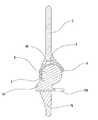
도 1은 보철물의 측 단면도이다.
도 1a는 도 1의 폴리에틸렌 라이닝(liner)과 대퇴 컵을 상세히 나타내는 부분 분해 단면도이다.
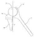
도 2는 대퇴골과 경골의 단면을 보여주는 이식된 보철물의 정면 입면도이다. 여기서, 대퇴골 요소는 대퇴골에 안착되고 경골 요소는 경골에 안착된다.
도 2a와 2b는 도 2의 대퇴 스템(stem)과 대퇴 컵의 2가지 실시예의 단면도이다.
도 3은 대퇴 컵의 사시도이다.
도 4는 활차 요소와 경골 트레이를 포함하는 경골 요소의 정면 사시도이다.
도 4a는 도 4의 경골 트레이의 평면도이다.
도 4b는 도 4A의 정면 입면도이다.
도 4c는 도 4A에 도시된 A-A를 따라 절단한 단면도이다.
도 4d는 나사 단면이 추가된 도 4의 활차 요소의 입면도이다.
도 4e는 도 4d의 저면도이다.
도 5는 활차 요소와 후방 리세스(posterior recess)를 보여주는 경골 요소의 배면도이다.
도 6은 후순이 후방 리세스에 위치하여 최대 굽힘을 허락하는 보철물의 측 입면도이다.
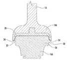
도 7은 본 발명의 대체 실시예의 단면도이다.The various objects, features, and attendant advantages of the present invention will be readily understood with reference to the accompanying drawings. In the drawings, the same reference numerals denote the same or similar parts.
1 is a side cross-sectional view of a prosthesis.
FIG. 1A is a partially exploded cross-sectional view showing the polyethylene liner and the femoral cup of FIG. 1 in detail. FIG.
2 is a front elevational view of an implanted prosthesis showing a cross-section of the femur and tibia; Here, the femoral component rests on the femur and the tibial component rests on the tibia.
Figures 2a and 2b are cross-sectional views of two embodiments of the stem and femoral cup of Figure 2;
3 is a perspective view of the femoral cup.
4 is a front perspective view of a tibia component including a pulley element and a tibial tray.
4A is a plan view of the tibia tray of FIG.
4B is a front elevational view of FIG. 4A.
4C is a cross-sectional view taken along line AA shown in FIG. 4A.
Figure 4d is an elevational view of the pulley element of Figure 4 with a threaded cross section added.
Fig. 4E is a bottom view of Fig. 4D. Fig.
Figure 5 is a rear view of a tibial component showing a pulley element and a posterior recess.
Fig. 6 is a side elevation view of the prosthesis that permits maximum bending in the backward position in the rear recess.
7 is a cross-sectional view of an alternate embodiment of the present invention.
도면을 참조하면, 본 발명은 일반적으로 대퇴골에 삽입되어 부착되는 스템(stem)(1 또는 1A)과 대퇴 컵(14)을 포함하는 대퇴골 요소를 포함한다. 조개 모양의 라이닝(lining)(2 또는 2A)이 대퇴 컵(14)의 오목면에 단단히 고정된다. 라이닝은 폴리에틸렌으로 구성되는 것이 바람직하지만 폴리에틸렌 외에 다른 물질도 종래 기술에 알려진 것처럼 라이닝으로 사용될 수 있다. 라이닝은 앞쪽으로부터 뒤쪽으로 배향된 릿지(ridge)(20)를 포함한다. 릿지(20)는 활차 요소(3)의 중앙 홈(21)에 관절로 이어진다. 라이닝은 가이드(Guide)(18)와 라이닝 잠금 탭(liner locking tabs)(24)에 의해 대퇴 컵에 단단히 고정된다. 분해 단면도 1A에 도시된 것처럼, 가이드(18)는 리세스(recess)(26)에 맞는 크기를 가진다. 리세스(26)는 측벽에 라이닝 잠금 리세스(27)를 갖는다. 가이드(18)가 리세스(26) 안으로 눌려짐에 따라, 라이닝 잠금 탭(24)이 가이드(18)의 측벽 방향으로 눌려지고, 가이드(18)가 완전히 리세스(26) 안으로 눌렸을 때 탈칵 소리를 내며 라이닝 잠금 리세스(27) 안으로 펴져서 라이닝(2)을 대퇴 컵(14)에 잠근다.Referring to the drawings, the present invention generally includes a femoral component including a stem (1 or 1A) and a femoral cup (14) inserted and attached to the femur. A shell-like lining (2 or 2A) is firmly secured to the concave surface of the femoral cup (14). The lining is preferably composed of polyethylene, but other materials besides polyethylene may also be used in the lining as is known in the art. The lining includes a
대퇴 컵은 후순(4 또는 4A)과 전순(5)을 포함한다. 전순(5)은 십자인대가 필요 없도록 후순(4 또는 4A)보다 길어야 한다.The femoral cup contains a posterior (4 or 4A) and anterior (5). The order (5) should be longer than the order (4 or 4A) so that the cruciate ligament is not necessary.
도면 4와 5를 참조하면, 활차 요소(3)는 좁아진 허리(21)를 갖는 횡 방향 굽은 몸체를 포함한다. 상기 활차 요소(3)는 고도로 연마된 표면을 갖고, 라이닝을 댄 대퇴 컵에 관절로 이어질 수 있다. 활차 요소는 목(16)에 의해 경골 트레이(19 또는 19A)에 부착된다. 후방에서 보면 (도 5), 목(16)과 활차 요소(3)는 최대 굽힘 시 대퇴 컵의 후순(4)을 수용하는 중앙 후방 리세스(23)를 제공한다 (도 5 참조).Referring to Figures 4 and 5, the pulley element 3 comprises a transversely curved body with a
경골 요소를 경골에 단단히 고정하는 다양한 방법이 있다는 것은 본 발명을 바탕으로 당업자들에게 명백할 것이다. 본 발명에서 2개의 경골 요소 실시예가 논의된다. 도 4에서, 경골에 이식되는 안정 기둥(posts)(22)을 구비한 경골 트레이(19)가 제공된다. 도 1, 2, 5, 6에서, 경골에 이식되는 리브(rib)(7A)을 갖는 안정 핀(Fin)(7)을 구비한 경골 트레이(19A)가 제공된다. 경골 트레이(19 또는 19A)는 도 4c에 단면도로 도시된 나사(31)와 같은 나사를 이용하여 경골에 더욱 단단하게 고정될 수 있다.It will be apparent to those skilled in the art based on the present invention that there are various ways to securely fix the tibial component to the tibia. Two tibial component embodiments are discussed in the present invention. In Fig. 4, a
경골 트레이가 경골에 단단히 고정된 후, 활차 요소(3)는 경골 트레이(19)에 단단히 고정된다. 이는 활차 요소(3)를 경골 트레이(19 또는 19A)의 슬롯(slot) 부분에 슬라이딩시켜서 달성된다. 경골 트레이는 라이닝 잠금 탭(24)과 같은 방식으로 기능하는 트레이 잠금 탭(17)을 포함한다. 활차 요소(3)가 경골 트레이로 슬라이드(slide) 될 때, 트레이 잠금 탭(17)이 슬롯(17A)이 트레이 잠금 탭(17) 위에 위치할 때까지 아래 방향으로 눌려지고, 그 후 탭(17)이 튀어 올라 활차 요소(3)를 제 위치에 잠근다.After the tibial tray is firmly fixed to the tibia, the pulley element 3 is firmly fixed to the
도 4a, b, c는 도 4의 경골 트레이(19)를 보다 자세히 도시한다. 경골 트레이(19)의 실시예는 안정 기둥(22), 슬롯 부분(6), 후방 노치(notch)(25), 선택적 나사 구멍(30)을 포함한다. 도 4c는 선택적 나사 구멍(30) 중 하나에 삽입된 편평머리나사(31)의 단면도를 도시한다. 경골 트레이는 나사, 핀, 시멘트, 또는 이들의 조합 등 당해 기술분야에 잘 알려진 다양한 수단으로 경골에 부착될 수 있다. 도 4의 경골 트레이(19)의 구조는, 경골 트레이(19A)가 안정 핀(7)을 포함하고, 경골 트레이(19)가 안정 기둥(22)을 포함한다는 차이점을 제외하고, 도 1, 2, 5 및 6의 경골 트레이(19A)의 구조와 동일하다.Figures 4a, b and c show the
도 4d는 도 4의 활차 요소(3)의 입면도이다. 활차 요소(3)는 중앙 홈(21), 목(16), 탭(32)을 포함한다. 도 4e는 도 4d의 저면도이다. 활차 요소(3)는 상기 설명된 바와 같이 탭(32)을 슬롯(6)으로 슬라이딩시키고 제자리에 잠금하여 경골 트레이(19)에 고정된다.Figure 4d is an elevation view of the pulley element 3 of Figure 4; The pulley element 3 includes a
상기 경골 트레이(19)는 최대 굽힘이 가능하도록 반원형 노치(25) (도 4a 및 5)을 포함한다.The
본 발명의 무릎 치환 보철물의 구성 부품을 포함하는 키트(Kit)는 다른 크기를 갖는 2개 이상의 시험용 플라스틱 임플란트와 시험용 플라스틱 임플란트와 동일한 크기를 갖는 2개 이상의 본 발명의 보철물을 포함한다. 따라서, 시험용 플라스틱 임플란트는 각각 스템과 대퇴 컵, 활차 요소 및 경골 요소를 포함한다. 또한, 다른 두께를 가진 2개 이상의 영구 라이닝이 2개 이상의 시험용 플라스틱 라이닝과 함께 키트에 포함되고, 각각의 시험용 플라스틱 라이닝은 영구 라이닝의 두께와 대응되는 두께를 가진다. 적당한 두께를 가진 폴리에틸렌 라이닝과 같은 영구 라이닝은 환자에게 가장 잘 맞는 보철물을 만들기 위하여 시험용 임플란트와 라이닝을 사용하여 수술 중에 선택된다. 시험용 플라스틱 라이닝의 구조는 가이드(18)가 잠금 탭(24)을 포함하지 않는다는 점에서 영구 라이닝과 다르다. 이것이 외과의사가 각각의 시험용 플라스틱 임플란트에서 다른 두께를 갖는 시험용 플라스틱 라이닝을 테스트할 수 있도록 한다.A kit comprising components of a knee replacement prosthesis of the present invention comprises two or more test plastic implants of different sizes and two or more inventive prostheses of the same size as the test plastic implants. Thus, the test plastic implants each include a stem and a femoral cup, a pulley element and a tibia element. Also, two or more permanent lining having different thicknesses are included in the kit with two or more test plastic lining, each of the test plastic lining having a thickness corresponding to the thickness of the permanent lining. Permanent lining, such as a polyethylene lining with a reasonable thickness, is selected during surgery using test implants and linings to create the prosthesis that best fits the patient. The construction of the test plastic lining differs from that of the permanent lining in that the
본 발명의 보철물 이식을 위한 수술 방법에서, 외과의사는 먼저 전방 중간선 절개를 시행할 것이다. 그 후, 무릎골이 측면으로 탈구되고, 무릎이 구부려진다. 다음으로, 우선 대퇴골이 골수내(intramedullary) 가이드 막대(rod)를 삽입함으로써 준비되고, 이어서 절개 가이드를 사용하여 적절한 원위(distal) 대퇴골 절개를 만든다. 이어서 절개 가이드를 사용하여 적절한 절개를 만들어서 경골이 준비된다. 다음, 시험용 플라스틱 임플란트가 임시로 환자에게 이식되고, 시험용 플라스틱 라이닝이 테스트된다. 그 후, 무릎의 운동 범위가 안정성이 있는지 점검한다. 안정성이 만족되면, 시험용 플라스틱 이식 요소를 제거하고, 시험용 임플란트 및 라이닝과 동일 크기를 가진 영구 보철물 및 라이닝으로 대체된다. 따라서, 경골 트레이가 제자리에 부착되고 대퇴 스템이 충격에 의하여 대퇴골에 부착된다. 무릎이 굽혀진 동안, 라이닝은 제자리에 잠겨진다. 그 후, 활차 요소는 경골 트레이에 부착된다. 무릎골은 무릎골의 관절 표면의 부상 정도에 따라 재포장이 필요하거나 필요 없을 수도 있다.In the surgical method for prosthetic implant of the present invention, the surgeon will first perform an anterior midline incision. Thereafter, the knee bone is dislocated to the side, and the knee is bent. Next, the femur is first prepared by inserting an intramedullary guide rod, and then using an incision guide to make an appropriate distal femoral incision. The tibia is then prepared by making an appropriate incision using an incision guide. Next, the test plastic implant is temporarily implanted in the patient and the test plastic lining is tested. After that, check whether the range of motion of the knee is stable. Once the stability is met, the test plastic implant is removed and replaced with a permanent prosthesis and lining of the same size as the test implant and lining. Thus, the tibial tray is attached in place and the femoral stem is attached to the femur by impact. While the knee is bent, the lining is locked in place. The pulley element is then attached to the tibial tray. The knee bone may or may not be repackaged depending on the degree of injury of the joint surface of the knee.
다음 사항은 개별적으로 또는 함께 결합하여 본 발명의 상기 실시예의 대안으로 고려될 수 있다.The following may be considered as alternatives to the above embodiments of the invention, either individually or in combination.
● 경골 및 대퇴골 요소는 티타늄과 같은 금속 또는 코발트 크롬과 같은 금속 합금으로 구성될 수 있다. 또한, 알루미나, 실리콘 나이트라이드(nitride) 등과 같은 세라믹 또는 의도한 목적을 위해 충분한 강도를 가진 생체적합 (biocompatible) 물질로 제작될 수 있다.The tibia and femoral component may be composed of a metal such as titanium or a metal alloy such as cobalt chromium. In addition, it can be made of ceramics such as alumina, silicon nitride, or the like or biocompatible material having sufficient strength for the intended purpose.
● 도 2에 도시된 고랑(trough)(15)은 대퇴골과 활차 요소(3) 사이의 공간이다. 활차가 대퇴 컵에 대하여 약간의 회전을 할 수 있도록 더 넓게 만들어질 수 있다.The
경골 요소가 활차 형상을 갖는 것 대신에, 중간 부분에 홈이 없는 곡면을 가질 수 있고, 대퇴 컵의 오목면은 바람직하지 않은 측면 움직임을 방지하는 구조에 적합한 모양을 가질 수 있다. 이 실시예의 단면도가 도 7에 도시되어 있다. 스템(1A)은 도 1의 스템(1)과 동일하지만, 대퇴 컵(14A)이 활차 요소(3A)의 단부에 걸쳐 연장되는 측면 부분을 가져서 활차 요소에 대한 대퇴 컵의 측면 운동을 제한하기 때문에, 대퇴 컵(14A)은 대퇴 컵(14)과 다르다. 목(16A)는 기본적으로 목(16) 구조와 동일하다. 폴리에틸렌 라이닝(2B)은 활차 요소(3A)의 상면에 관절로 이어지고, 폴리에틸렌 라이닝(2B)의 측면 부분(34)은 활차 요소(3A)의 단부(33)에 관절로 이어질 수 있다.Instead of having a tibial element having a pulley shape, the tibia element may have a groove-free surface in the middle portion, and the concave surface of the femoral cup may have a shape suitable for a structure that prevents undesirable lateral movement. A cross-sectional view of this embodiment is shown in Fig. The
Claims (13)
Translated fromKorean상기 대퇴골 요소는 근위 단부에 형성된 대퇴 컵과 원위 단부에 형성된 대퇴 스템을 갖고,
상기 대퇴 컵은 활차 요소의 관절에 대응하는 크기를 갖는 오목 접촉면을 포함하고, 제1 길이를 갖는 후순과 제1 길이보다 긴 제2 길이를 갖는 전순을 더 포함하고,
상기 활차 요소는 몸체의 두 말단 사이에 좁아진 허리를 갖는 굽은 몸체를 갖고, 최대 굽힘 시 후순을 수용하는 후방 리세스를 더 포함하고, 경골 트레이에 견고하게 부착되고,
상기 대퇴 컵의 오목 접촉면은 대퇴 컵의 오목면을 둘러쌓아서, 대퇴골 요소 및 활차 요소 사이의 압력 하중을 분산시키고, 바깥쪽으로 연장되고 활차 요소의 좁아진 허리 상에 관절로 이어지는 크기를 갖는 릿지를 갖는 것을 특징으로 하는,
무릎 보철물.A knee prosthesis including a femoral component, a pulley element, and a tibial tray,
The femoral component has a femoral cup formed at the proximal end and a femoral stem formed at the distal end,
Wherein the femoral cup further comprises an engaging surface having a dimension corresponding to the joint of the pulley element and having a second length greater than the first length and a rear having a first length,
The pulley element having a curved body having a waist narrowed between the two ends of the body and further comprising a rear recess for receiving a rear row at maximum bending,
The concave contact surface of the femoral cup has a ridge surrounding the concave surface of the femoral cup to disperse the pressure load between the femoral component and the pulley element and to extend outward and to the joint on the narrowed waist of the pulley element Features,
Knee prostheses.
상기 각각의 대퇴 컵은 활차 요소의 관절에 대응되는 크기를 갖는 오목면을 포함하고, 대퇴 컵의 오목면은 바깥쪽으로 연장되고 좁은 허리에 관절 연결될 수 있는 크기를 가진 릿지를 갖고,
상기 대퇴 컵은 제1 길이를 갖는 후순과 제1 길이보다 긴 제2 길이를 갖는 전순을 더 포함하고, 각각의 활차 요소는 최대 굽힘 시 후순을 수용하는 후방 리세스를 포함하고,
다른 두께를 갖는 2개 이상의 시험용 플라스틱 라이닝과, 그리고 1개 이상의 시험용 플라스틱 경골 트레이를 더 포함하고,
2개 이상의 청구항 1의 무릎 보철물과 2개 이상의 라이닝을 더 포함하고,
2개 이상의 청구항 1의 무릎 보철물 각각은 시험용 플라스틱 임플란트(Implant)의 크기와 대응되는 크기를 갖고, 2개 이상의 라이닝 각각은 시험용 플라스틱 라이닝의 두께에 대응되는 두께를 갖는 것을 특징으로 하는,
무릎 치환 수술에 사용되는 키트(Kit).Two or more test plastic femoral components of different sizes each having a femoral cup formed at the proximal end and a femoral stem formed at the distal end; And a curved body having a waist that is narrowed between two ends of the body, each body comprising two or more test plastic pulley elements of different sizes;
Each of the femoral cups including a concave surface having a size corresponding to the joint of the pulley element, the concave surface of the femoral cup having a ridge extending outward and sized to be articulated to the narrow waist,
The femoral cup further comprising a front row having a rear row having a first length and a second row having a second length greater than the first length, each of the row rolling elements including a rear recess for receiving a rear row at maximum bending,
Two or more test plastic lining having different thicknesses, and one or more test plastic tibial trays,
Claims 1. A knee prosthesis comprising two or more lap prostheses of claim 1 and two or more linings,
Each of the two or more knee prostheses according to claim 1 has a size corresponding to the size of the test plastic implant and each of the two or more lining has a thickness corresponding to the thickness of the test plastic lining.
Kits for knee replacement surgery.
상기 대퇴골 요소는 근위 단부에 형성된 대퇴 컵과 원위 단부에 형성된 대퇴 스템을 갖고, 대퇴 컵은 활차 요소의 관절에 대응되는 크기를 갖는 가진 오목면과 활차 요소의 말단 부분에 걸쳐 연장되는 크기를 가진 측면 부분을 포함하고,
상기 대퇴 컵은 제1 길이를 갖는 후순과 제1 길이보다 긴 제2 길이를 갖는 전순을 더 포함하고,
상기 활차 요소는 몸체의 두 말단 사이에 굽은 몸체를 갖고, 최대 굽힘 시 후순을 수용하는 후방 리세스를 더 포함하고, 경골 트레이에 견고하게 부착되는 것을 특징으로 하는,
무릎 보철물.A knee prosthesis including a femoral component, a pulley element, and a tibial tray,
Wherein the femoral component has a femoral cup formed at the proximal end and a femoral stem formed at the distal end, the femur cup having an engaging surface having a size corresponding to the joint of the pulley element, ≪ / RTI >
The femoral cup further comprising a folding sequence having a rear length having a first length and a second length longer than the first length,
Characterized in that the pulley element has a curved body between the two ends of the body and further comprises a rear recess for receiving a rear sequence at maximum bending and is rigidly attached to the tibial tray.
Knee prostheses.
13. The knee prosthesis of claim 12, wherein the lining is comprised of polyethylene.
Applications Claiming Priority (3)
| Application Number | Priority Date | Filing Date | Title |
|---|---|---|---|
| US201361883226P | 2013-09-27 | 2013-09-27 | |
| US61/883,226 | 2013-09-27 | ||
| PCT/US2014/057433WO2015048273A1 (en) | 2013-09-27 | 2014-09-25 | Reverse knee prosthesis |
Publications (2)
| Publication Number | Publication Date |
|---|---|
| KR20160078342A KR20160078342A (en) | 2016-07-04 |
| KR101891902B1true KR101891902B1 (en) | 2018-08-24 |
Family
ID=52744452
Family Applications (1)
| Application Number | Title | Priority Date | Filing Date |
|---|---|---|---|
| KR1020167009291AActiveKR101891902B1 (en) | 2013-09-27 | 2014-09-25 | Reverse knee prosthesis |
Country Status (12)
| Country | Link |
|---|---|
| US (1) | US9861485B2 (en) |
| EP (1) | EP3049027B1 (en) |
| JP (1) | JP6584389B2 (en) |
| KR (1) | KR101891902B1 (en) |
| CN (2) | CN105636554A (en) |
| BR (1) | BR112016006674B1 (en) |
| CA (1) | CA2924694C (en) |
| ES (1) | ES2723354T3 (en) |
| HK (1) | HK1223812A1 (en) |
| TR (1) | TR201905582T4 (en) |
| WO (1) | WO2015048273A1 (en) |
| ZA (1) | ZA201601995B (en) |
Families Citing this family (5)
| Publication number | Priority date | Publication date | Assignee | Title |
|---|---|---|---|---|
| US11071635B2 (en) | 2013-03-08 | 2021-07-27 | Mayo Foundation For Medical Education And Research | Shoulder prosthesis with variable inclination humeral head component |
| AU2017372734A1 (en)* | 2016-12-06 | 2019-06-27 | Mayo Foundation For Medical Education And Research | Shoulder prosthesis with variable inclination, offset, and version of humeral component |
| CN109464226B (en)* | 2017-09-08 | 2021-09-17 | 苏州黑桃医疗科技有限公司 | Silicon nitride ceramic artificial knee joint |
| US10595886B2 (en) | 2018-03-04 | 2020-03-24 | Joint Innovation Technology, Llc | Arthroscopic shoulder arthroplasty and method thereof |
| CN108836576A (en)* | 2018-07-18 | 2018-11-20 | 北京爱康宜诚医疗器材有限公司 | replacement prosthesis |
Citations (4)
| Publication number | Priority date | Publication date | Assignee | Title |
|---|---|---|---|---|
| US3840905A (en) | 1972-09-18 | 1974-10-15 | Nat Res Dev | Endoprosthetic knee joint |
| US4134158A (en) | 1977-08-22 | 1979-01-16 | Laure Prosthetics, Inc. | Knee joint prosthesis |
| US4249270A (en)* | 1978-10-06 | 1981-02-10 | Sulzer Brothers Limited | Endoprosthesis for a knee joint |
| US20040220675A1 (en)* | 2003-04-30 | 2004-11-04 | Lewis Ralph Harrison | Total elbow replacement for dogs |
Family Cites Families (27)
| Publication number | Priority date | Publication date | Assignee | Title |
|---|---|---|---|---|
| FR2076838A5 (en)* | 1970-01-30 | 1971-10-15 | Lyon Ass Arts Et Metiers | |
| US3694821A (en)* | 1970-11-02 | 1972-10-03 | Walter D Moritz | Artificial skeletal joint |
| US3868730A (en)* | 1973-09-24 | 1975-03-04 | Howmedica | Knee or elbow prosthesis |
| US3916451A (en)* | 1974-10-25 | 1975-11-04 | Frederick F Buechel | Floating center prosthetic joint |
| DE2522377A1 (en)* | 1975-05-21 | 1976-11-25 | Garlepp Hans Ewald Dr Med | Knee joint endoprosthesis with guide elements - limiting max. rotational movement of ball end in socket |
| US4470158A (en) | 1978-03-10 | 1984-09-11 | Biomedical Engineering Corp. | Joint endoprosthesis |
| US4224696A (en) | 1978-09-08 | 1980-09-30 | Hexcel Corporation | Prosthetic knee |
| US4309778A (en) | 1979-07-02 | 1982-01-12 | Biomedical Engineering Corp. | New Jersey meniscal bearing knee replacement |
| US5147405A (en)* | 1990-02-07 | 1992-09-15 | Boehringer Mannheim Corporation | Knee prosthesis |
| US6117175A (en)* | 1994-08-22 | 2000-09-12 | Bosredon; Jean | Spherical knee joint prosthesis |
| US5755803A (en) | 1994-09-02 | 1998-05-26 | Hudson Surgical Design | Prosthetic implant |
| IT1277091B1 (en)* | 1994-12-30 | 1997-11-04 | Jbs Sa | STABILIZED RECOVERY PROSTHESIS FROM BEHIND BY KNEE ARTICULATION |
| US5609642A (en)* | 1995-02-15 | 1997-03-11 | Smith & Nephew Richards Inc. | Tibial trial prosthesis and bone preparation system |
| US5776201A (en)* | 1995-10-02 | 1998-07-07 | Johnson & Johnson Professional, Inc. | Modular femoral trial system |
| US8545569B2 (en)* | 2001-05-25 | 2013-10-01 | Conformis, Inc. | Patient selectable knee arthroplasty devices |
| JP3002672B1 (en) | 1998-10-02 | 2000-01-24 | 真崎 修 | Artificial elbow joint member |
| FR2793404B1 (en) | 1999-05-14 | 2001-09-14 | Tornier Sa | ELBOW PROSTHESIS |
| US6503280B2 (en) | 2000-12-26 | 2003-01-07 | John A. Repicci | Prosthetic knee and method of inserting |
| US7141053B2 (en) | 2001-11-28 | 2006-11-28 | Wright Medical Technology, Inc. | Methods of minimally invasive unicompartmental knee replacement |
| USD473307S1 (en) | 2001-12-19 | 2003-04-15 | T. Derek V. Cooke | Knee prosthesis |
| ES2465090T3 (en)* | 2002-12-20 | 2014-06-05 | Smith & Nephew, Inc. | High performance knee prostheses |
| US8535383B2 (en)* | 2004-01-12 | 2013-09-17 | DePuy Synthes Products, LLC | Systems and methods for compartmental replacement in a knee |
| US8152815B2 (en)* | 2006-10-30 | 2012-04-10 | Wright Medical Technology, Inc. | Constrained acetabular trialing system |
| GB0812631D0 (en)* | 2008-07-10 | 2008-08-20 | Imp Innovations Ltd | Modular knee implants |
| CA2753488C (en)* | 2009-02-25 | 2014-04-29 | Mohamed Rashwan Mahfouz | Customized orthopaedic implants and related methods |
| CN102497837B (en)* | 2009-07-27 | 2015-12-02 | 托马斯·P·安瑞尔基 | Knee joint replacement system |
| US8496704B2 (en)* | 2010-04-13 | 2013-07-30 | Smith & Nephew, Inc. | Systems and methods for tensioning ligaments and other soft tissues |
- 2014
- 2014-09-25WOPCT/US2014/057433patent/WO2015048273A1/enactiveApplication Filing
- 2014-09-25USUS15/024,369patent/US9861485B2/enactiveActive
- 2014-09-25CNCN201480053061.2Apatent/CN105636554A/enactivePending
- 2014-09-25TRTR2019/05582Tpatent/TR201905582T4/enunknown
- 2014-09-25JPJP2016515380Apatent/JP6584389B2/ennot_activeExpired - Fee Related
- 2014-09-25KRKR1020167009291Apatent/KR101891902B1/enactiveActive
- 2014-09-25CNCN202010156167.2Apatent/CN111281618A/enactivePending
- 2014-09-25ESES14847813Tpatent/ES2723354T3/enactiveActive
- 2014-09-25EPEP14847813.4Apatent/EP3049027B1/enactiveActive
- 2014-09-25HKHK16112176.3Apatent/HK1223812A1/enunknown
- 2014-09-25BRBR112016006674-0Apatent/BR112016006674B1/enactiveIP Right Grant
- 2014-09-25CACA2924694Apatent/CA2924694C/enactiveActive
- 2016
- 2016-03-23ZAZA2016/01995Apatent/ZA201601995B/enunknown
Patent Citations (4)
| Publication number | Priority date | Publication date | Assignee | Title |
|---|---|---|---|---|
| US3840905A (en) | 1972-09-18 | 1974-10-15 | Nat Res Dev | Endoprosthetic knee joint |
| US4134158A (en) | 1977-08-22 | 1979-01-16 | Laure Prosthetics, Inc. | Knee joint prosthesis |
| US4249270A (en)* | 1978-10-06 | 1981-02-10 | Sulzer Brothers Limited | Endoprosthesis for a knee joint |
| US20040220675A1 (en)* | 2003-04-30 | 2004-11-04 | Lewis Ralph Harrison | Total elbow replacement for dogs |
Also Published As
| Publication number | Publication date |
|---|---|
| US9861485B2 (en) | 2018-01-09 |
| CN111281618A (en) | 2020-06-16 |
| JP6584389B2 (en) | 2019-10-02 |
| CN105636554A (en) | 2016-06-01 |
| EP3049027B1 (en) | 2019-02-06 |
| KR20160078342A (en) | 2016-07-04 |
| EP3049027A4 (en) | 2017-03-15 |
| US20160235540A1 (en) | 2016-08-18 |
| TR201905582T4 (en) | 2019-05-21 |
| WO2015048273A1 (en) | 2015-04-02 |
| EP3049027A1 (en) | 2016-08-03 |
| ZA201601995B (en) | 2020-05-27 |
| BR112016006674A2 (en) | 2017-08-01 |
| CA2924694A1 (en) | 2015-04-02 |
| JP2016531599A (en) | 2016-10-13 |
| HK1223812A1 (en) | 2017-08-11 |
| BR112016006674B1 (en) | 2021-12-14 |
| CA2924694C (en) | 2019-03-26 |
| ES2723354T3 (en) | 2019-08-26 |
Similar Documents
| Publication | Publication Date | Title |
|---|---|---|
| US6916341B2 (en) | Device and method for bicompartmental arthroplasty | |
| US9414926B2 (en) | Implant for restoring normal range flexion and kinematics of the knee | |
| AU2004208653B2 (en) | Prosthetic knee with removable stop pin for limiting anterior sliding movement of bearing | |
| CA2542619C (en) | High flexion articular insert | |
| JP2004113803A (en) | Joint part, rammer, method for providing shoulder arthroplasty, and kit for the same | |
| US20050102032A1 (en) | Knee joint prosthesis with a femoral component which links the tibiofemoral axis of rotation with the patellofemoral axis of rotation | |
| US11432932B2 (en) | Knee joint prosthesis and tibial component thereof | |
| JP2008253771A (en) | Mobile bearing assembly | |
| EA012197B1 (en) | Endoprosthetic elements for an ankle joint | |
| KR101891902B1 (en) | Reverse knee prosthesis | |
| US11344420B2 (en) | Modular knee prosthesis | |
| US9795489B2 (en) | System for a knee prosthetic | |
| GB2429648A (en) | Partial knee prosthesis |
Legal Events
| Date | Code | Title | Description |
|---|---|---|---|
| PA0105 | International application | Patent event date:20160408 Patent event code:PA01051R01D Comment text:International Patent Application | |
| PG1501 | Laying open of application | ||
| A201 | Request for examination | ||
| PA0201 | Request for examination | Patent event code:PA02012R01D Patent event date:20160727 Comment text:Request for Examination of Application | |
| E902 | Notification of reason for refusal | ||
| PE0902 | Notice of grounds for rejection | Comment text:Notification of reason for refusal Patent event date:20170630 Patent event code:PE09021S01D | |
| E90F | Notification of reason for final refusal | ||
| PE0902 | Notice of grounds for rejection | Comment text:Final Notice of Reason for Refusal Patent event date:20180226 Patent event code:PE09021S02D | |
| E701 | Decision to grant or registration of patent right | ||
| PE0701 | Decision of registration | Patent event code:PE07011S01D Comment text:Decision to Grant Registration Patent event date:20180521 | |
| GRNT | Written decision to grant | ||
| PR0701 | Registration of establishment | Comment text:Registration of Establishment Patent event date:20180820 Patent event code:PR07011E01D | |
| PR1002 | Payment of registration fee | Payment date:20180820 End annual number:3 Start annual number:1 | |
| PG1601 | Publication of registration | ||
| PR1001 | Payment of annual fee | Payment date:20210818 Start annual number:4 End annual number:4 | |
| PR1001 | Payment of annual fee | Payment date:20220718 Start annual number:5 End annual number:5 | |
| PR1001 | Payment of annual fee | Payment date:20230705 Start annual number:6 End annual number:6 | |
| PR1001 | Payment of annual fee | Payment date:20241204 Start annual number:7 End annual number:7 |