KR101891568B1 - Coupled hinges and flexible display device using the same - Google Patents
Coupled hinges and flexible display device using the sameDownload PDFInfo
- Publication number
- KR101891568B1 KR101891568B1KR1020160162806AKR20160162806AKR101891568B1KR 101891568 B1KR101891568 B1KR 101891568B1KR 1020160162806 AKR1020160162806 AKR 1020160162806AKR 20160162806 AKR20160162806 AKR 20160162806AKR 101891568 B1KR101891568 B1KR 101891568B1
- Authority
- KR
- South Korea
- Prior art keywords
- hinge body
- arm
- hinge
- arms
- state
- Prior art date
- Legal status (The legal status is an assumption and is not a legal conclusion. Google has not performed a legal analysis and makes no representation as to the accuracy of the status listed.)
- Active
Links
Images


Classifications
- G—PHYSICS
- G09—EDUCATION; CRYPTOGRAPHY; DISPLAY; ADVERTISING; SEALS
- G09F—DISPLAYING; ADVERTISING; SIGNS; LABELS OR NAME-PLATES; SEALS
- G09F9/00—Indicating arrangements for variable information in which the information is built-up on a support by selection or combination of individual elements
- G09F9/30—Indicating arrangements for variable information in which the information is built-up on a support by selection or combination of individual elements in which the desired character or characters are formed by combining individual elements
- G09F9/301—Indicating arrangements for variable information in which the information is built-up on a support by selection or combination of individual elements in which the desired character or characters are formed by combining individual elements flexible foldable or roll-able electronic displays, e.g. thin LCD, OLED
- G—PHYSICS
- G06—COMPUTING OR CALCULATING; COUNTING
- G06F—ELECTRIC DIGITAL DATA PROCESSING
- G06F1/00—Details not covered by groups G06F3/00 - G06F13/00 and G06F21/00
- G06F1/16—Constructional details or arrangements
- G06F1/1613—Constructional details or arrangements for portable computers
- G06F1/1633—Constructional details or arrangements of portable computers not specific to the type of enclosures covered by groups G06F1/1615 - G06F1/1626
- G06F1/1637—Details related to the display arrangement, including those related to the mounting of the display in the housing
- G06F1/1641—Details related to the display arrangement, including those related to the mounting of the display in the housing the display being formed by a plurality of foldable display components
- G—PHYSICS
- G06—COMPUTING OR CALCULATING; COUNTING
- G06F—ELECTRIC DIGITAL DATA PROCESSING
- G06F1/00—Details not covered by groups G06F3/00 - G06F13/00 and G06F21/00
- G06F1/16—Constructional details or arrangements
- G06F1/1613—Constructional details or arrangements for portable computers
- G06F1/1633—Constructional details or arrangements of portable computers not specific to the type of enclosures covered by groups G06F1/1615 - G06F1/1626
- G06F1/1637—Details related to the display arrangement, including those related to the mounting of the display in the housing
- G06F1/1652—Details related to the display arrangement, including those related to the mounting of the display in the housing the display being flexible, e.g. mimicking a sheet of paper, or rollable
- G—PHYSICS
- G06—COMPUTING OR CALCULATING; COUNTING
- G06F—ELECTRIC DIGITAL DATA PROCESSING
- G06F2203/00—Indexing scheme relating to G06F3/00 - G06F3/048
- G06F2203/041—Indexing scheme relating to G06F3/041 - G06F3/045
- G06F2203/04102—Flexible digitiser, i.e. constructional details for allowing the whole digitising part of a device to be flexed or rolled like a sheet of paper
Landscapes
- Engineering & Computer Science (AREA)
- Theoretical Computer Science (AREA)
- Computer Hardware Design (AREA)
- Physics & Mathematics (AREA)
- General Physics & Mathematics (AREA)
- Human Computer Interaction (AREA)
- General Engineering & Computer Science (AREA)
- Devices For Indicating Variable Information By Combining Individual Elements (AREA)
Abstract
Translated fromKoreanDescription
Translated fromKorean본 발명은 연동형 힌지와 이를 구비하는 플렉서블 디스플레이 디바이스에 관한 것으로 특히, 플렉서블 패널의 밴딩시 한계 곡률반경을 유지하도록 하여 플렉서블 패널의 파손을 방지할 수 있도록 한 연동형 힌지와 이를 이용한 플렉서블 디스플레이 디바이스에 관한 것이다.BACKGROUND OF THE INVENTION 1. Field of the Invention The present invention relates to an interlocking type hinge and a flexible display device having the interlocking type hinge. More particularly, the present invention relates to an interlocking type hinge for maintaining the limit radius of curvature during bending of the flexible panel to prevent breakage of the flexible panel, .
최근에는 각종 디스플레이 장치에 LCD(Liquid Crystal Display device), LED(Light Emitting Diode)와 같은 평판표시장치가 주로 이용되고 있다. 이러한 평판표시장치들은 얇은 두께, 가벼운 무게가 장점으로 최근에는 고화질 영상의 출력이 가능하게 되어 더 많은 분야의 디스플레이 장치에 이용되고 있다.
더욱이 최근에는 이러한 평판표시장치를 통해 실현하려 했던 기술 중 가장 중요한 기술인 플렉서블 기술 및 곡면화 기술이 진일보하여 이와 관련된 평판표시장치들의 개발이 활발히 이루어지고 있으며, 일부 제품은 상용화되어 출시되고 있다.
곡면화기 술은 생산기술의 발달로 대면적화 되는 평판표시장치를 사용하는 경우 사용자들의 몰입감을 높이고, 화면 전체의 시청효율을 높이기 위해 일정한 곡률로 만곡된 표시장치를 생산하고, 이러한 표시장치에서 왜곡 없이 영상을 표현하기 위한 기술을 의미한다. 이러한 곡면화 기술이 적용된 표시장치들은 130cm 급 화면을 가지는 표시장치의 생산에 적용되어 이미 일부 사용자들이 이용하고 있다.
또한, 플렉서블 기술은 과거에 비해 표시화면의 밴딩시 곡률의 한계점인 곡률반경이 크게 줄어들었으며, 구부림과 펼침의 반복에도 표시장치의 패널이 손상되지 않도록 하는 것이 가능해지고 있다. 이러한 플렉서블 기술을 통해 접이식 또는 롤식 디스플레이 장치를 제공하는 것이 가능해지며, 사용자의 편의에 따라 간편하게 화면의 면적을 자유자재로 조정하여 이용할 수 있는 환경이 마련되고 있다.
그러나 플렉서블 기술이 적용된 디스플레이 장치라 할지라도, 구부림의 한계 즉, 한계 곡률반경을 가지며, 한계 곡률반경 이상으로 구부러지는 경우 디스플레이장치가 파손되는 문제점이 있다. 이러한 문제를 해소하기 위해 디스플레이 장치의 특정 부분만이 구부러지도록 하고, 밴딩시 곡률한계를 보장하기 위한 장치를 사용하고 있으나, 종래의 곡률한계 보장을 위한 장치들은 구조가 복잡하여 생산이 어렵거나, 많은 부품으로 인해 무게가 무겁거나 부피가 큰 문제점이 있다.In recent years, flat panel display devices such as LCD (Liquid Crystal Display device) and LED (Light Emitting Diode) are mainly used for various display devices. These flat panel display devices have advantages of thin thickness and light weight, and recently, high-quality image output has become possible, and thus they are used in display devices of many fields.
In addition, in recent years, the flexible technology and the curved surface technology, which are the most important technologies to be realized through such a flat panel display device, have been advanced and the related flat panel display devices have been actively developed, and some products are being commercialized and released.
In the case of using a flat panel display device which is made large by the development of production technology, the curved surface technique produces a curved display device with a certain curvature in order to increase the immersion feeling of users and increase the viewing efficiency of the whole screen. Means a technique for expressing an image. The display devices to which such a curved surface technology is applied are applied to the production of a display device having a screen size of 130 cm and are already used by some users.
Further, in the flexible technology, the radius of curvature, which is the limit of the curvature at the time of bending the display screen, is greatly reduced compared to the past, and it is possible to prevent the panel of the display device from being damaged even when bending and unfolding are repeated. Such a flexible technology makes it possible to provide a folding or roll-type display device, and an environment in which the area of the screen can be freely adjusted and used with ease is provided.
However, even a display device to which a flexible technology is applied has a limitation of bending, that is, a limit radius of curvature, and when the display device is bent beyond the limit radius of curvature, there is a problem that the display device is broken. In order to solve such a problem, a device for bending only a specific portion of the display device and ensuring the curvature limit at the time of bending is used. However, the conventional devices for guaranteeing the curvature limit are difficult to manufacture due to the complicated structure, There are problems that the weight is heavy or bulky due to the parts.
따라서, 본 발명의 목적은 플렉서블 표시장치의 밴딩시 한계 곡률반경을 유지하도록 하여 표시장치의 파손을 방지할 수 있도록 한 연동형 힌지와 이를 이용한 플렉서블 디스플레이 디바이스를 제공하는 것이다.
또한, 본 발명의 다른 목적은 구조가 단순하고, 적은 부품으로 구현할 수 있어 경량화 및 작은 부피로 구현이 가능한 연동형 힌지와 이를 이용한 플렉서블 디스플레이 디바이스를 제공하는 것이다.
또한, 본 발명의 다른 목적은 플렉서블 표시장치 이외의 장치에서도 힌지에 의해 연결되는 구성 상호 간의 일정한 거리를 유지하거나, 한계 곡률반경을 보장해야 하는 장치에서 사용할 수 있도록 한 연동형 힌지와 이를 이용한 플렉서블 디스플레이 장치를 제공하는 것이다.Accordingly, it is an object of the present invention to provide an interlocking type hinge capable of preventing a breakage of a display device by maintaining a limit radius of curvature when bending a flexible display device, and a flexible display device using the interlocking type hinge.
Another object of the present invention is to provide an interlocking type hinge which is simple in structure and can be realized with a small number of parts and can be realized in a light weight and small volume, and a flexible display device using the same.
It is another object of the present invention to provide an interlocking type hinge which can be used in a device other than a flexible display device that can maintain a certain distance between components connected by a hinge or guarantee a limit radius of curvature and a flexible display Device.
상기 목적을 달성하기 위하여 본 발명의 일 실시 예에 따른 연동형 힌지는, 서로 다른 축(axis)을 중심으로 하는 회전 동작에 의해 접힌 상태와 펼친 상태를 전환하는 일측 힌지 바디(hinge body of one side) 및 타측 힌지 바디(hinge body of the other side); 일단(one end)이 일측 힌지 바디 또는 타측 힌지 바디의 상기 축(axis)에 각각 연결되고, 타단(the other end)이 타측 힌지 바디 또는 일측 힌지 바디와 결합하는 적어도 두 개 이상의 암들(arms); 및 상기 타단과 상기 타측 또는 일측 힌지 바디를 결합하는 결합 수단을 포함하되, 상기 암들은 상기 회전 동작에 따라 힌지 바디들의 상대적인 위치를 조절하는 것을 특징으로 한다.
여기서, 상기 결합 수단은, 타단(the other end)이 타측 힌지 바디 또는 일측 힌지 바디와 결합된 상태에서 이동이 가능하게 하되, 타단 측에 형성된 홀더; 및 힌지 바디 측에 형성된 가이드홈 또는 레일을 포함하는 것을 특징으로 한다.
여기서, 상기 일측 또는 타측 힌지 바디의 가이드홈 또는 레일은, 상대측 힌지 바디의 상기 축을 중심으로 하는 원의 궤적 상에 형성되는 것을 특징으로 한다.
여기서, 상기 적어도 두 개 이상의 암들(arms) 중에서, 제1 암과 제2 암의 중심은 새로운 축을 형성하고, 상기 새로운 축을 중심으로 제1 암과 제2 암이 상대적으로 회전하는 것을 특징으로 한다.
여기서, 상기 암은, 상기 접힌 상태에서는 일측 및 타측 힌지 바디 사이의 가로 간격을 특정시키고, 상기 펼친 상태에서는 일측 및 타측 파트 사이의 세로 거리를 특정시키는 것을 특징으로 한다.
여기서, 상기 제1 암 및 제2 암은, 상기 새로운 축을 중심으로 좌우 비대칭 형상을 하는 것을 특징으로 한다.
여기서, 제1 암 및 제2 암의 형상은, 판상의 비대칭 말굽 형태이고, 서로 원상과 거울상의 관계에 있는 것을 특징으로 한다.
본 발명의 일 실시 예에 따른 플렉서블 디스플레이 디바이스는, 접힘 및 펼침이 이루어지는 밴딩부가 형성되는 표시패널; 상기 밴딩부를 사이에 두고 상기 밴딩부 외의 상기 표시패널 하부에 분리되어 결합되는 일측 파트(part of one side)와 타측 파트(part of the other side); 및 상기 일측 파트와 타측 파트를 연결하는 연동형 힌지를 포함하고, 상기 연동형 힌지는, 상기 일측 파트 또는 타측 파트와 연결되고, 서로 다른 축(axis)을 중심으로 하는 회전 동작에 의해 접힌 상태와 펼친 상태를 전환하는 일측 힌지 바디(hinge body of one side) 및 타측 힌지 바디(hinge body of the other side); 일단(one end)이 일측 힌지 바디 또는 타측 힌지 바디의 상기 축(axis)에 각각 연결되고, 타단(the other end)이 타측 힌지 바디 또는 일측 힌지 바디와 결합하는 적어도 두 개 이상의 암들(arms); 및 상기 타단과 상기 타측 또는 일측 힌지 바디를 결합하는 결합 수단을 포함하되, 상기 암들은 상기 회전 동작에 따라 힌지 바디들의 상대적인 위치를 조절하는 것을 특징으로 한다.
여기서, 상기 결합 수단은, 타단(the other end)이 타측 힌지 바디 또는 일측 힌지 바디와 결합된 상태에서 이동이 가능하게 하되, 타단 측에 형성된 홀더; 및 힌지 바디 측에 형성된 가이드홈 또는 레일을 포함하는 것을 특징으로 한다.
여기서, 상기 적어도 두 개 이상의 암들(arms) 중에서, 제1 암과 제2 암의 중심은 새로운 축을 형성하고, 상기 새로운 축을 중심으로 제1 암과 제2 암이 상대적으로 회전하는 것을 특징으로 한다.
여기서, 상기 접힘 상태에서 상기 일측 및 타측 힌지 바디 사이의 가로 간격은, 상기 밴딩부의 한계 곡률반경에 의해 정해지고, 상기 펼침 상태에서 상기 일측 및 타측 힌지 바디 사이의 세로 거리는, 상기 밴딩부의 길이에 의해 정해지는 것을 특징으로 한다.
여기서, 상기 암은, 상기 펼친 상태에서 일측 파트와 타측 파트가 최대한 밀착하도록 세로 거리를 조절하는 것을 특징으로 한다.According to an aspect of the present invention, there is provided an interlocking type hinge comprising: a hinge body for one side, which is folded and unfolded by a rotation operation about different axes; And a hinge body of the other side; At least two arms each having one end connected to the axis of one side hinge body or the other side hinge body and the other end engaged with the other side hinge body or one side hinge body; And coupling means for coupling the other end and the other or one side hinge body, wherein the arms adjust the relative positions of the hinge bodies in accordance with the rotation operation.
Here, the coupling means may include a holder provided at the other end so as to be movable in a state where the other end is engaged with the other hinge body or one hinge body. And a guide groove or rail formed on the hinge body side.
Here, the guide groove or the rail of the one or the other hinge body is formed on the locus of the circle around the axis of the mating hinge body.
Here, among the at least two arms, the center of the first arm and the second arm forms a new axis, and the first arm and the second arm relatively rotate around the new axis.
Here, the arm is characterized by specifying the horizontal distance between one side and the other side hinge body in the folded state, and specifying the vertical distance between the one side and the other side part in the expanded state.
Here, the first arm and the second arm are asymmetrically shaped about the new axis.
Here, the shapes of the first arm and the second arm are asymmetrical horseshoe shapes in a plate shape, and are in a mirror-like relationship with the original shape.
A flexible display device according to an embodiment of the present invention includes: a display panel having a bending portion formed with folding and unfolding; A part of one side and a part of the other side separated and joined to the lower part of the display panel except the bending part with the bending part interposed therebetween; And an interlocking type hinge connecting the one side part and the other side part, wherein the interlocking type hinge is connected to the one side part or the other side part and is folded and folded by a rotation operation about different axes, A hinge body of one side and a hinge body of the other side for switching the opened state; At least two arms each having one end connected to the axis of one side hinge body or the other side hinge body and the other end engaged with the other side hinge body or one side hinge body; And coupling means for coupling the other end and the other or one side hinge body, wherein the arms adjust the relative positions of the hinge bodies in accordance with the rotation operation.
Here, the coupling means may include a holder provided at the other end so as to be movable in a state where the other end is engaged with the other hinge body or one hinge body. And a guide groove or rail formed on the hinge body side.
Here, among the at least two arms, the center of the first arm and the second arm forms a new axis, and the first arm and the second arm relatively rotate around the new axis.
Here, in the folded state, the horizontal distance between the one side and the other side hinge body is determined by the radius of curvature of the limiting portion of the bending portion, and the vertical distance between the one side and the other side hinge body in the extended state is determined by the length of the bending portion .
Here, the arm is characterized in that the vertical distance is adjusted so that one side part and the other side part come into close contact with each other as much as possible in the unfolded state.
본 발명에 따른 연동형 힌지와 이를 이용한 플렉서블 디스플레이 장치는 플렉서블 표시장치의 밴딩시 한계 곡률반경을 유지하도록 하여 표시장치의 파손을 방지할 수 있도록 하는 것이 가능하다.
또한, 본 발명에 따른 연동형 힌지와 이를 이용한 플렉서블 디스플레이 장치는 구조가 단순하고, 적은 부품으로 구현할 수 있어 경량화 및 작은 부피로 구현이 가능하다.
또한, 또한, 본 발명에 따른 연동형 힌지와 이를 이용한 플렉서블 디스플레이 장치는 플렉서블 표시장치 이외의 장치에서도 힌지에 의해 연결되는 구성 상호 간의 일정한 거리를 유지하거나, 한계 곡률반경을 보장해야 하는 장치에서 사용할 수 있다.The interlocking type hinge and the flexible display device using the interlocking type hinge according to the present invention can maintain the limit radius of curvature at the time of bending the flexible display device, thereby preventing breakage of the display device.
Further, the interlocking type hinge according to the present invention and the flexible display device using the same can be realized with a simple structure and a small number of parts, so that the interlocking type hinge can be reduced in weight and small in volume.
In addition, the interlocking type hinge according to the present invention and the flexible display device using the interlocking type hinge can be used in a device other than the flexible display device, which is required to maintain a constant distance between components connected by a hinge, or to secure a limit radius of curvature have.
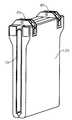
도 1은 연동형 힌지가 설치된 단말의 측면 예시도.
도 2는 펼쳐지거나 접혀지는 중간 상태의 힌지와 디바이스의 형태를 간략하게 도시한 측면도.
도 3은 완전히 펼쳐진 상태의 힌지와 디바이스 형태를 간략하게 도시한 측면도.
도 4는 연동형 힌지가 적용된 플렉서블 디스플레이 장치의 예를 도시한 측면 사시도.
도 5는 펼침 상태의 플렉서블 디스플레이 장치의 예를 도시한 사시도.
도 6은 본 발명의 실시 예에 따른 암의 형상 및 가이드홈을 설명하기 위한 예시도이다.1 is a side view of a terminal equipped with an interlocking type hinge;
Fig. 2 is a side view schematically illustrating the shape of the device and the hinge in an intermediate state that is unfolded or folded. Fig.
FIG. 3 is a side view schematically showing a hinge and a device form in a fully opened state; FIG.
4 is a side perspective view showing an example of a flexible display device to which an interlocking type hinge is applied;
5 is a perspective view showing an example of a flexible display device in an unfolded state;
6 is an exemplary view for explaining the shape of the arm and the guide groove according to the embodiment of the present invention.
이하, 본 발명의 바람직한 실시예를 첨부한 도면을 참조하여 당해 분야의 통상의 지식을 가진 자가 용이하게 실시할 수 있도록 설명하기로 한다. 첨부된 도면들에서 구성에 표기된 도면번호는 다른 도면에서도 동일한 구성을 표기할 때에 가능한 한 동일한 도면번호를 사용하고 있음에 유의해야 한다. 또한, 본 발명을 설명함에 있어서 관련된 공지의 기능 또는 공지의 구성에 대한 구체적인 설명이 본 발명의 요지를 불필요하게 흐릴 수 있다고 판단되는 경우에는 그 상세한 설명을 생략하기로 한다. 그리고 도면에 제시된 어떤 특징들은 설명의 용이함을 위해 확대 또는 축소 또는 단순화된 것이고, 도면 및 그 구성요소들이 반드시 적절한 비율로 도시되어 있지는 않다. 그러나 당업자라면 이러한 상세 사항들을 쉽게 이해할 것이다.
도 6은 본 발명의 실시 예에 따른 암의 형상 및 가이드홈을 설명하기 위한 예시도이다.
도 6을 참조하면, 폴더블 디바이스(20)의 일측 파트(20a) 및 타측 파트(20b)가 도시되어 있다. 여기서, 일측 및 타측은 폴더블 디바이스(20)에 형성되는 양측 영역 중에서 한쪽 및 나머지 한쪽을 의미한다. 설명의 편의상, 도면에서 좌측을 일측으로 우측으로 타측으로 규정한다.
도 6을 다시 참조하면, 일측 파트(20a)에는 일측 힌지 바디(60a)가 결합되어 있고, 타측 파트(20b)에는 타측 힌지 바디(60b)가 결합되어 있다. 그리고 연동형 힌지(40)의 제1 암(41a)은 일측 힌지 바디(60a)와 제2 축(51a)에서 연결되고, 타측 힌지 바디(60b)와는 홀더(53a)에서 연결된다. 다만, 홀더(53a)는 가이드홈(61b)를 따라 이동할 수 있다.
일측의 제2 축(51a)을 중심으로 일측 파트(20a) 및 일측 힌지 바디(60a)가 회전한다. 그리고 타측의 제2 축(51b)을 중심으로 타측 파트(20b) 및 타측 힌지 바디(60b)가 회전한다. 이렇듯, 서로 이격된 제2 축을 중심으로 각측 파트(20a, 20b)가 각각 회전하는 것은 한계 곡률반경 형성을 위함이다.
제2 축(51a, 51b)을 중심으로 일측 및 타측 파트(20a, 20b)가 회전하는 경우 생성되는 가상의 2개의 원이 파선으로 도시되어 있다. 2개의 원 중에서 안쪽 원은 제2 축(51a, 51b)에서 동일한 거리에 있는 지점에 제1 축(50)을 형성하기 위해 도시된다. 제1 축(50)은 2개의 안쪽 원이 만나는 상부 지점에 형성된다. 그리고 1차적으로 제1 축(50)과 일측의 제2 축(51a)을 연결하는 암이 형성된다. 1차적으로 형성된 암의 길이는 R1이다.
다음으로, 일측 파트(20a)와 타측 파트(20b)가 회전하는 동안 양측 파트의 사이의 최소 간격(R3)이 확보되도록 하기 위해 회전 궤적을 제한할 필요가 있다. 이러한 제한을 위해, 1차적으로 형성된 암을 연장하고, 연장된 타단을 타측 힌지 바디(60b)에 연결하는 것이 필요하다. 그리고 원활한 회전을 위해 상기 연장된 타단은 원 궤적을 따라 슬라이딩 이동이 가능해야 한다. 이에 따라, 제2 축(51a)에서 R2 거리의 원 궤적 상에 가이드홈(61b)이 형성된다.
위와 같이 형성된 제1 암(41a)이 도 6의 (B)에 도시되어 있다. 그리고 제1 암의(41a)의 형상은 도 6의 (C)와 같이 변형될 수 있다. 여기서 변형의 포인트는, 변형에도 불구하고 제1 축(50), 제2 축(51a) 및 홀더(53a)의 위치가 동일해야 한다. 같은 방법으로 제2 암(41b)이 형성될 수 있다.
본 발명의 일 실시 예에 따른 연동형 힌지(40)는, 일측 힌지 바디(60a) 및 타측 힌지 바디(60b) 그리고 힌지 바디들(60a, 60b)을 서로 연결하는 제1 암(41a) 및 제2 암(41b)을 포함한다.
일측 힌지 바디(60a)는 대상체의 일측 파트에 연결되고, 타측 힌지 바디(60b)는 대상체의 타측 파트에 연결된다. 여기서, 대상체는 2개의 파트로 구성되고, 각 파트는 연동형 힌지(40)에 의해 연결되어 접힘 및 펼침 상태를 전환하며 회전축을 중심으로 회전 동작, 즉 회동한다.
여기서, 대상체는 폴더블 디스플레이 디바이스 및/또는 폴더블 디스플레이 디바이스를 포함하는 폴더블 단말일 수 있다. 그리고 폴더블 디스플레이는 플렉서블 디스플레이 패널을 포함할 수 있다. 도 1은 연동형 힌지가 설치된 단말의 측면 예시도이다.
도 1을 참조하면, 힌지에 결합된 폴더블(foldable) 단말이 접힌 상태가 도시되어 있다. 단말은 폴더블 디스플레이 디바이스(20a, 20b)를 포함한다. 그리고 폴더블 디스플레이 디바이스(20a, 20b)는 폴더블 패널, 즉 플렉서블 패널(10)을 포함한다. 본 발명의 일 실시 예에 따른 연동형 힌지(40)는 폴더블 단말 및/또는 폴더블 디스플레이 디바이스가 접힘/펼침 상태를 전환하도록, 폴더블 단말 및/또는 폴더블 디스플레이 디바이스를 서로 연결한다. 이하, 설명의 편의를 위해 접힘/펼침의 대상이 되는 폴더블 단말 및/또는 폴더블 디스플레이 디바이스를 디바이스로 칭하기로 한다.
제1 암(41a) 및 제2 암(41b)은 양측 힌지 바디들(41a, 41b)에 결합된 디바이스(20a, 20b)가 접힘/펼침 상태 사이에서 회동 가능하게 일측 및 타측의 디바이스를 고정 및 지지하는 역할을 한다.
제1 암(41a)은 제1 축(50) 및 제2 축(51a, 53a)을 포함한다. 그리고 제2 암(41b)은 제1 축(50) 및 제2 축(53b, 51b)을 포함한다. 여기서, 제1 암(41a)과 제2 암(41b)은 제1 축(50)을 서로 공유한다. 즉 제1 축(50)에 제1 암(41a) 및 제2 암(41b)이 회동 가능하게 결합된다.
여기서, 연동형 힌지(40)에 결합되는 디바이스(20)의 일측 파트(20a) 및 타측 파트(20b)는 밴딩될 수 있다. 즉, 디바이스(20)는 완전히 접은 상태(0도의 밴딩각)와 완전히 펼친 상태(180도의 밴딩각) 사이의 상태 전환이 가능하다. 전체 180도의 밴딩각 중에서, 제1 암(41a)이 90도 범위를 담당하고, 제2 암(41b)이 나머지 90도 범위를 담당하여 디바이스(20)가 접힘 상태에서 펼침 상태가 될 수 있게 한다.
한편, 제1 암(41a)의 타측 종단(43b)에 홀더(53a)가 구비되고, 제2 암(41b)의 일측 종단(43a)에도 홀더(53b)가 구비된다. 홀더(53a)는 제1 암(41a)이 타측 힌지 바디(60b)와 마주대하는 면에 돌출되게 형성되며, 돌출된 부분이 타측 힌지 바디(60b)에 형성되는 가이드홈(61)에 안착된다. 마찬가지로, 홀더(53b)는 제2 암(41b)이 일측 힌지 바디(60a)와 마주대하는 면에 돌출되게 형성되며, 돌출된 부분이 타측 힌지 바디(60a)에 형성되는 가이드홈(61)에 안착된다.
그리고, 밴딩시 홀더(53)가 가이드홈(61)을 따라 이동하게 되어 디바이스(20)의 밴딩이 이루어질 수 있게 한다. 좀더 구체적으로 제1 암(41a)의 제2 축(51a)과 제2 암(41b)의 제2 축(51b) 사이의 간격은, 가이드홈(61)을 따라 슬라이딩 이동하는 홀더(53b, 53a)와 연결된 제1 암 및 제2 암의 종단(43b, 43a)에 의해 유지된다.
그리고, 이러한 가이드홈(61) 내에서의 홀더(53)의 이동을 제한하지 않기 위해 제2 축(51)이 홀더(53)에 비해 접힘 방향 즉, 밴딩되는 내측방향에 위치하게 된다. 즉, 홀더(53)의 움직임을 제한하지 않도록 하는 경우 제2 축(51)과 홀더(53)의 위치는 변경될 수도 있다.
제1 축(50)은 제1 암(41a)과 제2 암(41b)을 회전 가능하게 연결하며, 이들에 대해 회전을 위한 축의 역할을 한다. 제2 축(53b)은 제1 암(41a)과 일측 힌지 바디(60a), 제2 암(41b)과 타측 힌지 바디(60b)
또한, 힌지 바디(60)는 일측 및 타측 힌지 바디 쌍으로 구성되고, 일측 및 타측 힌지 바디(60a, 60b)에는 전술한 바와 같이 가이드홈(61)이 형성된다. 이 가이드홈(61)은 연동형 힌지(40)에 의해 밴딩시 가이드(60)에 결합된 디바이스가 일정한 간격으로 회전할 수 있도록 도 1에 도시된 바와 같인 곡선형태로 형성된다.
도 2 및 도 3은 연동형 힌지(40)에 의한 밴딩을 설명하기 위한 예시도로서, 도 2는 0도에서 180도 사이의 밴딩각 중에서 임의의 밴딩각 상태의 연동형 힌지(40)와 디바이스(20a, 20b)의 형상을 간략하게 도시한 측면도이다. 그리고, 도 3은 완전히 펼쳐진 상태의 연동형 힌지(40)와 디바이스(20a, 20b) 형상을 간략하게 도시한 측면도이다.
도 1 내지 3을 참조하면, 본 발명의 실시 예에 따른 연동형 힌지(40)는 일측 파트(20a) 및 타측 파트(20b)의 접힘과 펼쳐짐을 위한 관절의 역할을 한다. 특히, 연동형 힌지(40)는 한 쌍의 암(41a, 41b)과 힌지 바디(60)에 의해 양측 파트들(20a, 20b)이 일정한 거리, 일정한 각도로 쌍을 이루어 회전하도록 하는 역할을 한다.
이러한 거리의 유지는 우선 제1 축(50)과 제2 축(51)에 의해 일정한 거리를 유지하는 한편, 회전이 가능하게 하면서도, 제1 축(50)과 가이드홈(61)에 의해 회전에 따라 경로를 제한함으로써 이루어진다.
이러한 연동형 힌지(40)는 도 1과 같이 접힌 상태를 유지하게 할 수 있다. 이때 힌지(40)에 의해 양측 파트들(20a, 20b)은 도시된 바와 같이 나란한 형태로 배치되고, 양측 파트들(20a, 20b)의 마주하는 면에 구성되는 표시패널(10)은 밴딩부(11)가 만곡된 상태로 유지된다. 그리고, 이러한 밴딩부(11)의 곡률을 유지할 수 있도록 제1 파트(20a)와 제2 파트(20b)는 이격되도록 연동형 (40)에 의해 간극이 유지된다.
좀 더 구체적으로 제1 파트(20a)와 제2 파트(20b)의 간격은 제1 암(41a)과 제2 암(41b)의 제1 축(50)과 제2 축(51)을 연결하는 부분에 의해 유지가 되고, 제1 암(41a)과 제2 암(41b)의 제1 파트(20a)와 제2 파트(20b)의 나란한 상태는 제1 축(50)과 홀더(53)를 연결하는 부분이 가이드홈(61)에 의해 이동이 제한됨으로써 유지된다. 즉, 가이드홈(61)이 도 1에 도시된 것보다 제1 축(50) 방향으로 더 연장된 길이를 가지는 경우 제1 파트(20a) 및 제2 파트(20b)는 도시된 바와 같은 평행상태를 유지하지 못하고, 밴딩부(11)와 반대되는 부분의 파트(20a, 20b)가 서로 교차되는 형태로 배열되게 된다.
이와 같은 상태에서 두 개의 파트(20a, 20b)를 펼치게 되면, 가이드(60)와 제2 축(51)에 의해 파트(20a, 20b)가 회전하고, 타측에서는 홀더(53)가 가이드홈(61)을 따라 이동하면서 양측 파트(20a, 20b)가 펼쳐지게 된다.
좀 더 구체적으로 제1 암(41a)을 예로 들어 설명하면, 제1 암(41a)의 일측 종단(43b)이 제2축(51b)에 의해 제1 가이드(60a)에 회동 가능하게 결합된 상태에서 제1가이드(60a)가 펼침에 의해 회전을 하게 된다. 마찬가지로, 제2 파트(20b)도 제2 축(51a)에 의해 타측 힌지 바디(60b)가 회전을 하게 된다. 이때 제1 축(50)과 제2 축(51a)을 잇는 제1 암(41a)과 제1 축(50)과 제2 축(51b)를 잇는 제2 암(41b)에 의해 가이드(60)는 제1 축(50)을 축으로 하여 회전하게 된다.
그리고, 제1 암(41a)의 타측 종단(43a)에 형성된 홀더(53a)가 가이드홈(61)을 따라 이동하게 됨으로써, 파트(20a, 20b)가 제2 축(51)을 축으로 곡률반경을 저해하는 형태로 회전하는 것을 방지하게 되며, 이러한 제한을 동일한 형태의 제1 암(41a)과 제2 암(41b)에 의해 수행되도록 함으로써 제1 파트(20a) 및 제2 파트(20b)가 동일한 각도로 회전을 하게 된다.
이후 완전히 펼쳐진 상태에서는 홀더(53)가 가이드홈(61)의 타측 종단으로 완전히 이동함으로써 두 개의 파트(20a, 20b)가 일직선을 유지하는 펼친 상태가 된다. 이때, 가이드홈(61)이 제1 축(50)과 멀어지는 방향으로 더 연장되어 형성되는 경우 '〈'와 같은 형태로 파트(20a, 20b)가 표시패널(10)이 배치되지 않은 위치로 더 굽혀지게 된다.
이와 같이 본 발명의 연동형 힌지(40)는 서로 쌍을 이루되 제1 축(50)을 기준으로 대를 이루게 제1 축(50)에 결합되는 제1 암(41a) 및 제2 암(41b)를 가이드(60)에 형성되는 가이드홈(61) 및 가이드(60)에 결합되는 제2 축(51)에 의해 구속함으로써 파트(20a, 20b)의 회전시의 반경 및 거리를 일정하게 유지하는 것이 가능해진다.
도 4는 연동형 힌지가 적용된 플렉서블 디스플레이 장치의 예를 도시한 측면 사시도이고, 도 5는 펼침 상태의 플렉서블 디스플레이 장치의 예를 도시한 사시도이다.
도 4 및 도 5를 참조하면, 본 발명에 따른 연동형 힌지가 적용된 플렉서블 디스플레이 장치는 표시패널(10), 프레임(120) 및 연동형 힌지(40)를 포함하여 구성된다
표시패널(10)은 프레임(120)의 일측 파트(20a)와 타측 파트(20b)에 고정되어, 구동부(미도시)로부터 공급되는 전원 및 데이터에 의해 화상을 표시한다. 이를 위해 표시패널(10)은 박막형태로 형성되며, 일부분이 밴딩될 수 있는 표시소자에 의해 플렉서블하게 제조되며, 일례로, 액정표시장치, 유기/무기 발광표시장치(Light emitting diode)와 같은 표시소자에 의해 구성될 수 있다.
이러한 표시패널(10)은 서로 이격되어 나란하게 배치(접힌 상태)되는 비밴딩부(12)에 결합되어 고정되고, 밴딩부(11)는 두 개의 파트(20a, 20b) 사이에 형성되는 간극에 위치하게 된다. 이를 위해, 표시패널(10)은 일부분만 밴딩 가능한 형태로 형성될 수 있으나, 이로써 본 발명을 한정하는 것은 아니다.
프레임(120)은 표시패널(10)을 고정하고 표시패널(10)의 구동을 위한 구동부(미도시) 및 전원부(미도시)를 포함한다. 특히, 프레임(120)은 접힘 상태에서 간극을 두고 서로 이격되어 배치되는 일측 파트(20a) 및 타측 파트(20b)로 구성된다. 여기서, 밴딩부(11)가 프레임(120)의 센터 폴드 라인에 형성되는 것으로 도시되어 있으나, 이에만 한정될 것은 아니므로 밴딩부(11)는 프레임(120)의 전체 영역에서 복수로 형성될 수 있다. 다만, 설명의 편의를 위해 프레임(120)의 센터 폴더 라인에 형성된 밴딩부(11)를 예를 들어 설명하기로 한다.
프레임(120)은 합성수지 또는 금속 재질로 구현될 수 있다. 프레임(120)의 일면은 표시패널(10)의 배면에 형성된다. 프레임(120)은 전술한 바와 같이 밴딩부(11)를 사이에 두고 한 쌍 이상의 파트(20a, 20b)로 구성될 수 있다.
일례로 프레임이(120)이 한 쌍의 파트(20a, 20b)로 구성되는 경우, 일측 파트(20a)는 일측 힌지 바디(60a)와 결합하고, 타측 파트(20b)는 타측 힌지 바디(60b)와 결합한다. 즉 일측 파트(20a) 및 타측 파트(20b)는 일정거리를 유지한 상태로 회전 가능하도록 연동형 힌지(40)를 통해 서로 결합된다. 이때, 표시패널(10)의 밴딩부(11)가 접힌 일측 파트(20a) 및 타측 파트(20b) 사이의 간극에 위치하게 되어 연동형 힌지(40)에 의해 프레임(120)이 회동하는 경우 표시패널(10)의 밴딩, 즉 접힘/펼침 상태의 전환이 일어난다.
여기서, 힌지 바디(60a, 60b)는 양측 파트(20a, 20b)와는 별도로 제작되어 양측 파트(20a, 20b)에 결합되거나, 프레임(120)과 일체형으로 형성될 수 있으며, 제시된 바에 의해 본 발명이 한정하는 것은 아니다.
도 5를 참조하면, 전체 프레임(120) 영역에서, 구동부 및 전원부 등의 구성을 포함하고 있는 연동형 힌지(40)가 결합된 부위가 다른 부위에 비해 두께가 더 길게 도시되어 있으나, 반드시 이에 한정되는 것은 아니며 프레임(120)이 일정 두께로 형성될 수도 있다.
연동형 힌지(40)는 일측 파트(20a) 및 타측 파트(20b)를 회전 가능하게 연결한다. 특히, 연동형 힌지(40)는 일측 파트(20a) 및 타측 파트(20b)의 회전시 표시패널(10)이 한계 곡률반경보다 같거나 큰 반경을 유지하면서 밴딩될 수 있게 일측 파트(20a) 및 타측 파트(20b)의 상대적인 거리와 회전 각도가 일정하게 유지되도록 하는 역할을 한다. 즉, 연동형 힌지(40)는 일측 파트(20a) 및 타측 파트(20b)의 회전에 의해 접힘이 발생하는 경우, 밴딩부(11)가 한계 곡률반경 미만의 반경으로 접히는 것을 방지하여 밴딩시 표시패널(10)이 손상되는 것을 방지하게 된다. 이러한 연동형 힌지(40)의 구성은 도 1 내지 4 및 이와 관련된 설명의 연동형 힌지(40)와 동일하므로 이에 대한 상세한 설명은 생략하기로 한다.
이상에서 본 발명의 기술적 사상을 예시하기 위해 구체적인 실시 예로 도시하고 설명하였으나, 본 발명은 상기와 같이 구체적인 실시 예와 동일한 구성 및 작용에만 국한되지 않고, 여러 가지 변형이 본 발명의 범위를 벗어나지 않는 한도 내에서 실시될 수 있다. 따라서, 그와 같은 변형도 본 발명의 범위에 속하는 것으로 간주해야 하며, 본 발명의 범위는 후술하는 특허청구범위에 의해 결정되어야 한다.Hereinafter, preferred embodiments of the present invention will be described with reference to the accompanying drawings so that those skilled in the art can easily carry out the present invention. It should be noted that the drawings denoted by the same reference numerals in the drawings denote the same reference numerals whenever possible, in other drawings. In the following description of the present invention, a detailed description of known functions and configurations incorporated herein will be omitted when it may make the subject matter of the present invention rather unclear. And certain features shown in the drawings are to be enlarged or reduced or simplified for ease of explanation, and the drawings and their components are not necessarily drawn to scale. However, those skilled in the art will readily understand these details.
6 is an exemplary view for explaining the shape of the arm and the guide groove according to the embodiment of the present invention.
Referring to Fig. 6, one
6, one
The one-
Two imaginary circles generated when one side and the
Next, it is necessary to limit the rotation locus so that the minimum interval R3 between the two side parts is secured while the one
The
The interlocking
One
Here, the object may be a foldable terminal including a folderable display device and / or a folderable display device. And the folderable display may include a flexible display panel. 1 is a side view of a terminal equipped with an interlocking type hinge.
Referring to FIG. 1, a foldable terminal coupled to a hinge is shown folded. The terminal includes a
The
The
Here, one
On the other hand, a
Then, the holder 53 is moved along the
The second shaft 51 is positioned in the folding direction, that is, the inner side in which the holder 53 is bent, so as not to restrict the movement of the holder 53 in the
The
The
2 and 3 are diagrams for explaining the banding by the interlocking
Referring to FIGS. 1 to 3, the interlocking
The distance is maintained by the
The interlocking
More specifically, the interval between the
When the two
More specifically, the
The
The holder 53 is completely moved to the other end of the
As described above, the interlocking
FIG. 4 is a side perspective view showing an example of a flexible display device to which an interlocking type hinge is applied, and FIG. 5 is a perspective view showing an example of a flexible display device in an unfolded state.
4 and 5, the flexible display device to which the interlocking type hinge according to the present invention is applied includes a
The
The
The
The
For example, when the
Here, the
Referring to FIG. 5, in the area of the
The interlocking
While the present invention has been particularly shown and described with reference to exemplary embodiments thereof, it is to be understood that the invention is not limited to the disclosed exemplary embodiments, but, on the contrary, And the like. Accordingly, such modifications are deemed to be within the scope of the present invention, and the scope of the present invention should be determined by the following claims.
10: 디스플레이 패널
20: 디바이스
20a: 일측 파트
20b: 타측 파트
120: 프레임
40: 연동형 힌지
41a: 제1 암
41b: 제2 암
43a: 일측 종단
43b: 타측 종단
50: 제1 축
51a: 일측 제2 축
51b: 타측 제2 축
53: 홀더
60a: 일측 힌지 바디
60b: 타측 힌지 바디
61: 가이드홈10: Display panel
20: Device
20a: one side part
20b: the other part
120: frame
40: Interlocking hinge
41a: first cancer
41b: second arm
43a: one end
43b: the other end
50: 1st axis
51a: one side second axis
51b: the other second axis
53: Holder
60a: One side hinge body
60b: the other hinge body
61: Guide groove
Claims (12)
Translated fromKorean일단(one end)이 일측 힌지 바디 또는 타측 힌지 바디의 상기 축(axis)에 각각 연결되고, 타단(the other end)이 타측 힌지 바디 또는 일측 힌지 바디와 결합하는 적어도 두 개 이상의 암들(arms); 및
상기 타단과 상기 타측 또는 일측 힌지 바디를 결합하는 결합 수단을 포함하되,
상기 암들은 상기 회전 동작에 따라 힌지 바디들의 상대적인 위치를 조절하는 것을 특징으로 하는, 연동형 힌지.A hinge body of one side and a hinge body of the other side for switching the folded state and the expanded state by a rotation operation about different axes;
At least two arms each having one end connected to the axis of one side hinge body or the other side hinge body and the other end engaged with the other side hinge body or one side hinge body; And
And coupling means for coupling the other end and the other or one side hinge body,
Wherein the arms adjust the relative position of the hinge bodies in accordance with the rotational movement.
상기 결합 수단은,
타단(the other end)이 타측 힌지 바디 또는 일측 힌지 바디와 결합된 상태에서 이동이 가능하게 하되,
타단 측에 형성된 홀더; 및
힌지 바디 측에 형성된 가이드홈 또는 레일을 포함하는 것을 특징으로 하는, 연동형 힌지.The method according to claim 1,
Wherein the coupling means comprises:
The other end is movable in a state of being coupled with the other hinge body or one hinge body,
A holder formed on the other end side; And
And a guide groove or a rail formed on the hinge body side.
상기 일측 또는 타측 힌지 바디의 가이드홈 또는 레일은,
상대측 힌지 바디의 상기 축을 중심으로 하는 원의 궤적 상에 형성되는 것을 특징으로 하는, 연동형 힌지.The method of claim 2,
The guide grooves or the rails of the one or the other hinge body may be formed,
Is formed on a locus of a circle centered on the axis of the mating hinge body.
상기 적어도 두 개 이상의 암들(arms) 중에서,
제1 암과 제2 암의 중심은 새로운 축을 형성하고,
상기 새로운 축을 중심으로 제1 암과 제2 암이 상대적으로 회전하는 것을 특징으로 하는, 연동형 힌지.The method according to claim 1,
Of the at least two arms,
The centers of the first and second arms form a new axis,
Wherein the first arm and the second arm relatively rotate about the new axis.
상기 암은,
상기 접힌 상태에서는 일측 및 타측 힌지 바디 사이의 가로 간격을 특정시키고,
상기 펼친 상태에서는 일측 및 타측 파트 사이의 세로 거리를 특정시키는 것을 특징으로 하는, 연동형 힌지.The method according to claim 1,
The arm
In the folded state, a horizontal gap between the one side and the other side hinge body is specified,
And the longitudinal distance between the one side and the other side is specified in the open state.
상기 제1 암 및 제2 암은,
상기 새로운 축을 중심으로 좌우 비대칭 형상을 하는 것을 특징으로 하는, 연동형 힌지.The method of claim 4,
Wherein the first arm and the second arm include:
And a left-right asymmetric shape about the new axis.
제1 암 및 제2 암의 형상은,
판상의 비대칭 말굽 형태이고, 서로 원상과 거울상의 관계에 있는 것을 특징으로 하는, 연동형 힌지.The method of claim 4,
The shape of the first arm and the second arm,
Shaped asymmetric horseshoe shape, and are in a mirror image relationship with each other.
상기 밴딩부를 사이에 두고 상기 밴딩부 외의 상기 표시패널 하부에 분리되어 결합되는 일측 파트(part of one side)와 타측 파트(part of the other side); 및
상기 일측 파트와 타측 파트를 연결하는 연동형 힌지를 포함하고,
상기 연동형 힌지는,
상기 일측 파트 또는 타측 파트와 연결되고, 서로 다른 축(axis)을 중심으로 하는 회전 동작에 의해 접힌 상태와 펼친 상태를 전환하는 일측 힌지 바디(hinge body of one side) 및 타측 힌지 바디(hinge body of the other side);
일단(one end)이 일측 힌지 바디 또는 타측 힌지 바디의 상기 축(axis)에 각각 연결되고, 타단(the other end)이 타측 힌지 바디 또는 일측 힌지 바디와 결합하는 적어도 두 개 이상의 암들(arms); 및
상기 타단과 상기 타측 또는 일측 힌지 바디를 결합하는 결합 수단을 포함하되,
상기 암들은 상기 회전 동작에 따라 힌지 바디들의 상대적인 위치를 조절하는 것을 특징으로 하는, 플렉서블 디스플레이 디바이스.A display panel on which a bending portion for folding and unfolding is formed;
A part of one side and a part of the other side separated and joined to the lower part of the display panel except the bending part with the bending part interposed therebetween; And
And an interlocking type hinge connecting the one side part and the other side part,
The interlocking type hinge includes:
A hinge body of one side and a hinge body of one side connected to the one side part or the other side part for switching the folded state and the expanded state by a rotation operation about different axes, the other side);
At least two arms each having one end connected to the axis of one side hinge body or the other side hinge body and the other end engaged with the other side hinge body or one side hinge body; And
And coupling means for coupling the other end and the other or one side hinge body,
Wherein the arms adjust the relative position of the hinge bodies in accordance with the rotation movement.
상기 결합 수단은,
타단(the other end)이 타측 힌지 바디 또는 일측 힌지 바디와 결합된 상태에서 이동이 가능하게 하되,
타단 측에 형성된 홀더; 및
힌지 바디 측에 형성된 가이드홈 또는 레일을 포함하는 것을 특징으로 하는, 플렉서블 디스플레이 디바이스.The method of claim 8,
Wherein the coupling means comprises:
The other end is movable in a state of being coupled with the other hinge body or one hinge body,
A holder formed on the other end side; And
And a guide groove or a rail formed on the hinge body side.
상기 적어도 두 개 이상의 암들(arms) 중에서,
제1 암과 제2 암의 중심은 새로운 축을 형성하고,
상기 새로운 축을 중심으로 제1 암과 제2 암이 상대적으로 회전하는 것을 특징으로 하는, 플렉서블 디스플레이 디바이스.The method of claim 8,
Of the at least two arms,
The centers of the first and second arms form a new axis,
And wherein the first arm and the second arm rotate relative to each other about the new axis.
상기 접힘 상태에서 상기 일측 및 타측 힌지 바디 사이의 가로 간격은,
상기 밴딩부의 한계 곡률반경에 의해 정해지고,
상기 펼침 상태에서 상기 일측 및 타측 힌지 바디 사이의 세로 거리는,
상기 밴딩부의 길이에 의해 정해지는 것을 특징으로 하는, 플렉서블 디스플레이 디바이스.The method of claim 8,
And the horizontal spacing between the one side and the other side hinge body in the folded state,
The radius of curvature of the bending portion,
In the unfolded state, the vertical distance between the one side and the other side hinge body,
And the length of the bending portion is determined by the length of the bending portion.
상기 암은,
상기 펼친 상태에서 일측 파트와 타측 파트가 최대한 밀착하도록 세로 거리를 조절하는 것을 특징으로 하는, 플렉서블 디스플레이 디바이스.The method of claim 8,
The arm
Wherein the vertical distance is adjusted so that one side part and the other side part come into close contact with each other as much as possible in the unfolded state.
Priority Applications (1)
| Application Number | Priority Date | Filing Date | Title |
|---|---|---|---|
| KR1020160162806AKR101891568B1 (en) | 2016-12-01 | 2016-12-01 | Coupled hinges and flexible display device using the same |
Applications Claiming Priority (1)
| Application Number | Priority Date | Filing Date | Title |
|---|---|---|---|
| KR1020160162806AKR101891568B1 (en) | 2016-12-01 | 2016-12-01 | Coupled hinges and flexible display device using the same |
Publications (2)
| Publication Number | Publication Date |
|---|---|
| KR20180062757A KR20180062757A (en) | 2018-06-11 |
| KR101891568B1true KR101891568B1 (en) | 2018-08-27 |
Family
ID=62601153
Family Applications (1)
| Application Number | Title | Priority Date | Filing Date |
|---|---|---|---|
| KR1020160162806AActiveKR101891568B1 (en) | 2016-12-01 | 2016-12-01 | Coupled hinges and flexible display device using the same |
Country Status (1)
| Country | Link |
|---|---|
| KR (1) | KR101891568B1 (en) |
Cited By (2)
| Publication number | Priority date | Publication date | Assignee | Title |
|---|---|---|---|---|
| KR20200058020A (en)* | 2018-11-19 | 2020-05-27 | 엘지디스플레이 주식회사 | Display device |
| WO2021025180A1 (en)* | 2019-08-02 | 2021-02-11 | 엘지전자 주식회사 | Mobile terminal |
Families Citing this family (10)
| Publication number | Priority date | Publication date | Assignee | Title |
|---|---|---|---|---|
| KR102623906B1 (en)* | 2018-12-27 | 2024-01-10 | 엘지디스플레이 주식회사 | Tiled display device |
| KR102223632B1 (en)* | 2019-03-13 | 2021-03-05 | 주식회사 에스코넥 | A hinge device installed on a flexible display panel |
| KR102709937B1 (en)* | 2019-05-23 | 2024-09-26 | 삼성디스플레이 주식회사 | Foldable display device |
| KR102043107B1 (en)* | 2019-06-20 | 2019-11-11 | 주식회사 삼화플라스틱 | Hinge device and hidden hinge container |
| KR102296241B1 (en)* | 2019-07-17 | 2021-09-01 | 주식회사 파인테크닉스 | In-folding type flexible display |
| CN111105711B (en)* | 2019-11-28 | 2021-05-18 | 联想(北京)有限公司 | Electronic equipment |
| KR102279103B1 (en)* | 2020-11-03 | 2021-07-19 | 노완동 | Link Hinge Structure |
| KR102540825B1 (en)* | 2021-07-05 | 2023-06-12 | (주)연우 | Container whose hinge part is hidden from the outside |
| KR20240054322A (en)* | 2021-09-16 | 2024-04-25 | 엘지전자 주식회사 | Hinge device and display device having the same |
| KR102545433B1 (en)* | 2021-11-16 | 2023-06-20 | 정민우 | Hinges for smart display devices |
Citations (1)
| Publication number | Priority date | Publication date | Assignee | Title |
|---|---|---|---|---|
| KR101604826B1 (en) | 2014-05-23 | 2016-03-21 | 주식회사 다이아벨 | Hinge Device and Electronic Device having it |
Family Cites Families (1)
| Publication number | Priority date | Publication date | Assignee | Title |
|---|---|---|---|---|
| KR102210047B1 (en) | 2014-03-05 | 2021-02-01 | 엘지디스플레이 주식회사 | Foldable display apparatus |
- 2016
- 2016-12-01KRKR1020160162806Apatent/KR101891568B1/enactiveActive
Patent Citations (1)
| Publication number | Priority date | Publication date | Assignee | Title |
|---|---|---|---|---|
| KR101604826B1 (en) | 2014-05-23 | 2016-03-21 | 주식회사 다이아벨 | Hinge Device and Electronic Device having it |
Cited By (3)
| Publication number | Priority date | Publication date | Assignee | Title |
|---|---|---|---|---|
| KR20200058020A (en)* | 2018-11-19 | 2020-05-27 | 엘지디스플레이 주식회사 | Display device |
| KR102650633B1 (en) | 2018-11-19 | 2024-03-25 | 엘지디스플레이 주식회사 | Display device |
| WO2021025180A1 (en)* | 2019-08-02 | 2021-02-11 | 엘지전자 주식회사 | Mobile terminal |
Also Published As
| Publication number | Publication date |
|---|---|
| KR20180062757A (en) | 2018-06-11 |
Similar Documents
| Publication | Publication Date | Title |
|---|---|---|
| KR101891568B1 (en) | Coupled hinges and flexible display device using the same | |
| KR101861077B1 (en) | Hinge and flexible diplay device including the same | |
| US11134579B2 (en) | Hinge module and electronic device | |
| US11762426B2 (en) | Display system with a flexible display | |
| KR102197040B1 (en) | Infolding Hinge Structure for Flexible Display Panel | |
| KR102709937B1 (en) | Foldable display device | |
| KR102362096B1 (en) | Display device | |
| US20210333838A1 (en) | Foldable Display Device | |
| WO2020258887A1 (en) | Support apparatus for flexible screen, foldable display module, and display device | |
| KR20230074267A (en) | Foldable devices and electronic devices | |
| US11474570B2 (en) | Hinge structure for foldable device having flexible display panel | |
| KR20190043613A (en) | Flexible screen support device and flexible screen | |
| JP2020053001A (en) | Foldable display device and hinge device | |
| TW202032318A (en) | Foldable display device | |
| KR20240165395A (en) | Damping mechanism, hinge device and foldable electronic device | |
| CN111899649A (en) | Support structure and foldable display device | |
| KR102311588B1 (en) | Foldable Display Device | |
| CN110162141A (en) | A kind of non-overlapping formula linkage suitable for Folding screen | |
| TWM589420U (en) | Collapsible hinge shaft structure for flexible display screen | |
| CN108962036B (en) | Foldable display device | |
| KR101583451B1 (en) | Hinge Device and Electronic Device having it | |
| KR102041498B1 (en) | Hinge module for flexible display | |
| KR20200106798A (en) | Hinge gear system of portable device within flexible display | |
| CN211009548U (en) | Folding rotary shaft structure of flexible display screen | |
| CN209746453U (en) | Display screen folding structure |
Legal Events
| Date | Code | Title | Description |
|---|---|---|---|
| A201 | Request for examination | ||
| PA0109 | Patent application | Patent event code:PA01091R01D Comment text:Patent Application Patent event date:20161201 | |
| PA0201 | Request for examination | ||
| E902 | Notification of reason for refusal | ||
| PE0902 | Notice of grounds for rejection | Comment text:Notification of reason for refusal Patent event date:20171231 Patent event code:PE09021S01D | |
| E701 | Decision to grant or registration of patent right | ||
| PE0701 | Decision of registration | Patent event code:PE07011S01D Comment text:Decision to Grant Registration Patent event date:20180525 | |
| PG1501 | Laying open of application | ||
| GRNT | Written decision to grant | ||
| PR0701 | Registration of establishment | Comment text:Registration of Establishment Patent event date:20180820 Patent event code:PR07011E01D | |
| PR1002 | Payment of registration fee | Payment date:20180820 End annual number:3 Start annual number:1 | |
| PG1601 | Publication of registration | ||
| PR1001 | Payment of annual fee | Payment date:20210817 Start annual number:4 End annual number:4 | |
| PR1001 | Payment of annual fee | Payment date:20220801 Start annual number:5 End annual number:5 | |
| PR1001 | Payment of annual fee | Payment date:20230809 Start annual number:6 End annual number:6 | |
| PR1001 | Payment of annual fee | Payment date:20240801 Start annual number:7 End annual number:7 |