KR101890986B1 - Multi sleeve for cables support apparatus and cables support apparatus comprising the same - Google Patents
Multi sleeve for cables support apparatus and cables support apparatus comprising the sameDownload PDFInfo
- Publication number
- KR101890986B1 KR101890986B1KR1020160103742AKR20160103742AKR101890986B1KR 101890986 B1KR101890986 B1KR 101890986B1KR 1020160103742 AKR1020160103742 AKR 1020160103742AKR 20160103742 AKR20160103742 AKR 20160103742AKR 101890986 B1KR101890986 B1KR 101890986B1
- Authority
- KR
- South Korea
- Prior art keywords
- resistant layer
- layer
- pod
- abrasion
- flexible member
- Prior art date
- Legal status (The legal status is an assumption and is not a legal conclusion. Google has not performed a legal analysis and makes no representation as to the accuracy of the status listed.)
- Active
Links
Images


Classifications
- H—ELECTRICITY
- H02—GENERATION; CONVERSION OR DISTRIBUTION OF ELECTRIC POWER
- H02G—INSTALLATION OF ELECTRIC CABLES OR LINES, OR OF COMBINED OPTICAL AND ELECTRIC CABLES OR LINES
- H02G3/00—Installations of electric cables or lines or protective tubing therefor in or on buildings, equivalent structures or vehicles
- H02G3/02—Details
- H02G3/04—Protective tubing or conduits, e.g. cable ladders or cable troughs
- H02G3/0406—Details thereof
- B—PERFORMING OPERATIONS; TRANSPORTING
- B23—MACHINE TOOLS; METAL-WORKING NOT OTHERWISE PROVIDED FOR
- B23Q—DETAILS, COMPONENTS, OR ACCESSORIES FOR MACHINE TOOLS, e.g. ARRANGEMENTS FOR COPYING OR CONTROLLING; MACHINE TOOLS IN GENERAL CHARACTERISED BY THE CONSTRUCTION OF PARTICULAR DETAILS OR COMPONENTS; COMBINATIONS OR ASSOCIATIONS OF METAL-WORKING MACHINES, NOT DIRECTED TO A PARTICULAR RESULT
- B23Q11/00—Accessories fitted to machine tools for keeping tools or parts of the machine in good working condition or for cooling work; Safety devices specially combined with or arranged in, or specially adapted for use in connection with, machine tools
- F—MECHANICAL ENGINEERING; LIGHTING; HEATING; WEAPONS; BLASTING
- F16—ENGINEERING ELEMENTS AND UNITS; GENERAL MEASURES FOR PRODUCING AND MAINTAINING EFFECTIVE FUNCTIONING OF MACHINES OR INSTALLATIONS; THERMAL INSULATION IN GENERAL
- F16L—PIPES; JOINTS OR FITTINGS FOR PIPES; SUPPORTS FOR PIPES, CABLES OR PROTECTIVE TUBING; MEANS FOR THERMAL INSULATION IN GENERAL
- F16L57/00—Protection of pipes or objects of similar shape against external or internal damage or wear
- H—ELECTRICITY
- H01—ELECTRIC ELEMENTS
- H01B—CABLES; CONDUCTORS; INSULATORS; SELECTION OF MATERIALS FOR THEIR CONDUCTIVE, INSULATING OR DIELECTRIC PROPERTIES
- H01B7/00—Insulated conductors or cables characterised by their form
- H01B7/17—Protection against damage caused by external factors, e.g. sheaths or armouring
- H01B7/18—Protection against damage caused by wear, mechanical force or pressure; Sheaths; Armouring
Landscapes
- Engineering & Computer Science (AREA)
- General Engineering & Computer Science (AREA)
- Mechanical Engineering (AREA)
- Architecture (AREA)
- Civil Engineering (AREA)
- Structural Engineering (AREA)
- Electric Cable Arrangement Between Relatively Moving Parts (AREA)
- Details Of Indoor Wiring (AREA)
- Supports For Pipes And Cables (AREA)
- Protection Of Pipes Against Damage, Friction, And Corrosion (AREA)
Abstract
Translated fromKoreanDescription
Translated fromKorean본 발명은 케이블류 보호장치용 다중 슬리브 및 이를 포함하는 케이블류 보호장치에 관한 것이다. 구체적으로, 본 발명은 반복적인 이동을 수행하는 공작기계, 전자기기, 산업용 로보트, 운반기계 등의 이동체에 사용되는 케이블류를 보호하고 더욱 안정적으로 지지함으로써 상기 케이블류의 손상을 방지할 수 있을 뿐만 아니라, 내구성이 우수하여 반복적인 굴곡이동에도 손상되지 않기 때문에 신뢰성이 높아 결과적으로 분진에 의한 공정 오류 및 케이블류 손상을 억제할 수 있어 반도체 웨이퍼 같은 초정밀 및 고순도 제품의 생산공정에 적합한 케이블류 보호장치용 다중 슬리브 및 이를 포함하는 케이블류 보호장치에 관한 것이다.BACKGROUND OF THE INVENTION 1. Field of the Invention The present invention relates to a multi-sleeve for a cable current protection device and a cable current protection device including the same. More specifically, the present invention protects and more reliably supports cables used in moving bodies such as machine tools, electronic devices, industrial robots, and conveying machines that perform repetitive movement, thereby preventing damage to the cables Since it has excellent durability, it is not damaged by repetitive bending movement. Therefore, it is highly reliable, and consequently, it can suppress process errors and damages of cables due to dust. Therefore, it is suitable for production process of ultra-high precision and high purity products such as semiconductor wafers. And a cabling protection device including the same.
공작기계, 전자기기, 산업용 로버트, 운반기계 등의 이동체에 사용되는 전선 케이블, 광섬유 케이블, 유체 공급호스 등의 가요성 케이블이나 호스 등(이하, '케이블류'라 칭한다)은 상기 이동체의 이동에 따른 상기 케이블류의 뒤틀림, 케이블류 상호간의 마찰이나 상기 케이블류에 인가되는 인장력, 굽힘력 등에 의해 손상될 수 있기 때문에, 상기 케이블류를 보호하고 안정적으로 지지함으로써 상기 이동체에 사용되는 케이블류의 손상을 방지할 수 있는 케이블류 보호장치가 사용되고 있다.Flexible cables and hoses (hereinafter referred to as "cables"), such as wire cables, optical fiber cables and fluid supply hoses used in mobile bodies such as machine tools, electronic devices, industrial robots, The cable can be damaged by the warping of the cable, the friction between the cables, the tensile force applied to the cable, the bending force, etc. Therefore, the cable can be protected and stably supported, A cable protection device is used.
종래 케이블류 보호장치는 케이블류에 해당하는 전선 케이블, 유체 공급호스 등이 각각 삽입되는 하나 이상의 포드(pod)를 포함하는 가요성 다중 슬리브를 포함하고, 상기 다중 슬리브는 가요성을 구현하기 위해 통상 고분자 소재로 이루어질 수 있으며, 상기 다중 슬리브를 구성하는 상부 가요성 부재와 하부 가요성 부재가 부분적으로 접합됨으로써 상기 하나 이상의 포드(pod)를 형성할 수 있다.Conventional cable guards include flexible multiple sleeves including one or more pods into which cable cables, fluid supply hoses, etc., corresponding to cables, respectively, are inserted, The at least one pod may be formed by partially joining the upper flexible member and the lower flexible member constituting the multiple sleeves.
그러나, 종래 케이블류 보호장치에 포함되는 상기 가요성 다중 슬리브는 공작기계, 전자기기, 산업용 로버트, 운반기계 등의 이동체에 적용되는 경우 반복적으로 굴곡이동함에 따라 상기 가요성 다중 슬리브를 구성하는 상부 가요성 부재와 하부 가요성 부재의 접합부가 국소적으로 손상될 수 있고, 상기 손상된 접합부에서 상부 가요성 부재와 하부 가요성 부재 사이에 틈이 형성될 수 있으며, 이러한 틈을 통해 상기 포드(pod) 내부의 분진 등이 외부로 유출되어 초정밀 및 고순도 제품의 생산공정에서의 공정 오류를 유발하거나 인접한 케이블류들이 서로 마찰에 의해 손상될 수 있다.However, when the flexible multislip included in the conventional cable protection device is applied to a moving body such as a machine tool, an electronic device, an industrial robot, a conveying machine, and the like, the flexible multislip is repeatedly flexed, A joint between the flexible member and the lower flexible member may be locally damaged and a gap may be formed between the upper flexible member and the lower flexible member at the damaged joint, Dust may leak out to cause process errors in the production process of ultra-precise and high-purity products, or adjacent cable streams may be damaged by friction with each other.
따라서, 반복적인 이동을 수행하는 공작기계, 전자기기, 산업용 로보트, 운반기계 등의 이동체에 사용되는 케이블류를 보호하고 더욱 안정적으로 지지함으로써 상기 케이블류의 손상을 방지할 수 있을 뿐만 아니라, 내구성이 우수하여 반복적인 굴곡이동에도 손상되지 않기 때문에 신뢰성이 높아 결과적으로 분진에 의한 공정 오류 및 케이블류 손상을 억제할 수 있어 반도체 웨이퍼 같은 초정밀 및 고순도 제품의 생산공정에 적합한 케이블류 보호장치용 다중 슬리브 및 이를 포함하는 케이블류 보호장치가 절실히 요구되고 있는 실정이다.Therefore, it is possible to protect the cables used in moving bodies such as machine tools, electronic apparatuses, industrial robots, conveying machines, and the like which perform repetitive movement and to more stably support the cables, Since it is excellent and it is not damaged even by repetitive bending movements, it is highly reliable. As a result, process errors and damages due to dust can be suppressed. Therefore, it is possible to provide a multi-sleeve for a cable protection device suitable for a production process of ultra- And a cable protection device including such a cable is strongly desired.
본 발명은 공작기계, 전자기기, 산업용 로보트, 운반기계 등의 이동체에 사용되는 케이블류를 보호하고 더욱 안정적으로 지지함으로써 상기 케이블류의 손상을 방지할 수 있는 케이블류 보호장치용 다중 슬리브 및 이를 포함하는 케이블류 보호장치를 제공하는 것을 목적으로 한다.The present invention relates to a multi-sleeve for a cable-protecting device capable of preventing the cables from being damaged by protecting and more stably supporting the cables used in moving bodies such as machine tools, electronic devices, industrial robots, The present invention has been made in view of the above problems.
또한, 본 발명은 내구성이 우수하여 반복적인 굴곡이동에도 손상되지 않기 때문에 신뢰성이 높아 결과적으로 분진에 의한 공정 오류 및 케이블류 손상을 억제할 수 있어 반도체 웨이퍼 같은 초정밀 및 고순도 제품의 생산공정에 적합한 케이블류 보호장치용 다중 슬리브 및 이를 포함하는 케이블류 보호장치를 제공하는 것을 목적으로 한다.In addition, since the present invention has excellent durability and is not damaged even by repeated bending movement, it is highly reliable, and consequently, it is possible to suppress process errors and damages of cables due to dust. As a result, a cable suitable for a production process of ultra- The present invention provides a multi-sleeve protection device and a cable protection device including the same.
상기 과제를 해결하기 위해, 본 발명은,In order to solve the above problems,
케이블, 유체 공급호스 또는 가이드 체인이 삽입되어 수용될 수 있는 하나 이상의 포드(pod)를 포함하는 케이블류 보호장치용 다중 슬리브로서, 상기 다중 슬리브는 상부 가요성 부재 및 하부 가요성 부재의 부분적 접합에 의해 형성되고, 상기 포드는 상기 상부 가요성 부재와 상기 하부 가요성 부재의 접합부들 사이의 접합되지 않는 부분에 의해 형성되며, 상기 상부 가요성 부재는 가요성 수지로 이루어진 신축층, 상기 신축층의 상부 및 하부 표면 각각에 배치되고 마찰계수가 낮은 수지로 이루어진 내마모층, 상기 신축층과 상기 내마모층 사이에서 이들을 서로 접합시키는 접착 조성물에 의해 형성된 접착층을 포함하고, 상기 내마모층 중 상기 신축층의 하부 표면에 배치되어 상기 포드의 내면을 형성하는 내마모층은 동일하거나 상이한 길이의 간격으로 이격되는 복수개의 내마모층 컬럼을 포함하고, 상기 복수개의 내마모층 컬럼 중 좌측 및 우측의 최외측 내마모층 컬럼은 이들의 외측 말단 각각이 상기 다중 슬리브의 좌측 및 우측 말단의 외곽선으로부터 동일하거나 상이한 길이의 간격으로 이격되어 있으며, 상기 하부 가요성 부재는 상기 상부 가요성 부재와 대칭되는 적층 구조를 갖고, 상기 상부 가요성 부재에 포함된 내마모층 컬럼 사이 및 말단에 형성된 간격과 상기 하부 가요성 부재에 포함된 내마모층 컬럼 사이 및 말단에 형성된 간격을 통해 각각 유출되는 접착 조성물이 서로 접합됨으로써 상기 접합부가 형성되는, 다중 슬리브를 제공한다.A multislice for a cable-current protection device comprising at least one pod into which a cable, a fluid supply hose or a guide chain can be inserted and received, the multisleeve comprising at least one of a pair of upper and lower flexible members, Wherein the upper flexible member is formed by an unbonded portion between the upper flexible member and the lower flexible member, and the upper flexible member is formed by a stretchable layer made of a flexible resin, An abrasion-resistant layer disposed on each of the upper and lower surfaces and made of a resin having a low coefficient of friction, and an adhesive layer formed by a bonding composition for bonding the abrasion-resistant layer and the abrasion-resistant layer between them, The abrasion resistant layer, which is disposed on the lower surface of the layer and forms the inner surface of the pod, Wherein the left and right outermost wear wear layer columns of the plurality of wear wear layer columns are arranged such that each of their outer ends is identical to the outline of the left and right ends of the multiple sleeves Or spaced apart by different lengths of length, said lower flexible member having a laminated structure symmetrical to said upper flexible member, wherein a gap formed between and at the ends of the wear resistant layer columns included in said upper flexible member, And the adhesive composition flowing out through the gap formed between the abrasion-resistant layer columns and the end portions included in the flexible member are bonded to each other to form the abutment.
여기서, 상기 포드의 내면을 형성하는 내마모층은 아래 수학식 1의 조건을 만족하는 것을 특징으로 하는, 다중 슬리브를 제공한다.Wherein the abrasion resistant layer forming the inner surface of the pod satisfies the following condition (1).
[수학식 1][Equation 1]
y=ax+0.15[bd+1]±0.15y = ax + 0.15 [bd + 1] + 0.15
상기 수학식 1에서,In the above equation (1)
d는 임의의 포드에 삽입되는 케이블류의 최대 단면적과 동일한 단면적을 갖는 원의 직경(mm)이고,d is the diameter (mm) of the circle having the same cross-sectional area as the maximum cross-sectional area of the cable streams inserted in an arbitrary pod,
x는 상기 포드를 형성하는 내마모층 컬럼의 폭 길이(mm)이고,x is the width (mm) of the width of the wear resistant layer forming the pod,
y는 상기 내마모층 컬럼과 인전합 다른 내마모층 컬럼 사이의 간격 또는 최외곽 내마모층 컬럼 말단의 간격(mm)이고,y is an interval between the wear resistant layer column and another wear resistant layer column or the interval (mm) between the end portions of the wear resistant layer of the outermost wearable layer,
a는 0.08 내지 0.12이고,a is from 0.08 to 0.12,
b는 0.09 내지 0.10이다.b is 0.09 to 0.10.
또한, 상기 포드에 삽입되는 케이블류의 최대 단면적과 동일한 단면적을 갖는 원의 직경(d)은 3.8 내지 10.0 mm, 상기 포드를 형성하는 내마모층 컬럼의 폭 길이(x)는 15 내지 23 mm, 상기 내마모층 컬럼과 인전합 다른 내마모층 컬럼 사이의 간격 또는 최외곽 내마모층 컬럼 말단의 간격(y)은 1.5 내지 2.5 mm인 것을 특징으로 하는, 다중 슬리브를 제공한다.The diameter d of the circle having the same cross-sectional area as the maximum cross-sectional area of the claws inserted into the pod is 3.8 to 10.0 mm, the width x of the abrasion-resistant layer forming the pod is 15 to 23 mm, Wherein the gap between the abrasion-resistant layer column and the other abrasion-resistant layer column or the interval y between the ends of the abrasion-resistant layer at the outermost abrasive layer is 1.5 to 2.5 mm.
한편, 상기 신축층의 두께는 0.2 내지 0.4 mm, 내마모층의 두께는 0.05 내지 0.15 mm, 상기 접착층의 두께는 0.025 내지 0.075 mm인 것을 특징으로 하는, 다중 슬리브를 제공한다.The thickness of the elastic layer is 0.2 to 0.4 mm, the thickness of the wear-resistant layer is 0.05 to 0.15 mm, and the thickness of the adhesive layer is 0.025 to 0.075 mm.
그리고, 상기 신축층은 폴리우레탄 수지를 포함하는 것을 특징으로 하는, 다중 슬리브를 제공한다.And the elastic layer comprises a polyurethane resin.
나아가, 상기 내마모층은 팽창 폴리테트라플루오로에틸렌(ePTFE) 수지를 포함하는 것을 특징으로 하는, 다중 슬리브를 제공한다.Further, the wear resistant layer is characterized in that it comprises an expanded polytetrafluoroethylene (ePTFE) resin.
또한, 상기 접착 조성물은 핫멜트를 포함하는 것을 특징으로 하는, 다중 슬리브를 제공한다.The present invention also provides a multiple sleeve characterized in that the adhesive composition comprises hot melt.
그리고, 적어도 하나의 상기 내마모층은 복수의 미세기공이 형성된 다공성 수지를 포함하고, 상기 복수의 미세기공 중 적어도 일부에 대전 방지 입자가 포함되는 것을 특징으로 하는, 다중 슬리브를 제공한다.And, at least one abrasion-resistant layer includes a porous resin having a plurality of micropores formed therein, and at least a part of the plurality of micropores includes antistatic particles.
여기서, 상기 대전 방지 입자는 전도성 나노 카본, 전도성 나노 금속, 전도성 폴리머 및 이오노머로 이루어진 그룹으로부터 선택된 1종 이상의 양전하 또는 음전하를 띄는 입자를 포함하는 것을 특징으로 하는, 다중 슬리브를 제공한다.Wherein the antistatic particles comprise at least one positively charged or negatively charged particle selected from the group consisting of a conductive nanocarbon, a conductive nanometal, a conductive polymer, and an ionomer.
또한, 적어도 하나의 상기 내마모층은 작은 단위체들이 사슬 혹은 그물 형태로 결합되어 미세 그물망 형태로 형성된 고분자 수지를 포함하고, 상기 미세 그물망 형태의 조직에 대전 방지 입자가 붙어 있는 것을 특징으로 하는, 다중 슬리브를 제공한다.The at least one abrasion resistant layer may further comprise a polymer resin formed by combining the small unit pieces in a chain or net form in the form of a fine mesh, and the fine mesh type structure is attached with antistatic particles. Provide a sleeve.
나아가, 상기 접합부에서 상기 접착층과 상기 신축층이 모두 용융되어 접합되는 것을 특징으로 하는, 다중 슬리브를 제공한다.Further, the adhesive layer and the elastic layer are both melted and bonded at the joint portion.
한편, 상기 다중 슬리브; 상기 다중 슬리브의 하나 이상의 포드에 삽입되어 수용되는 가이드 체인; 및 상기 다중 슬리브의 양 말단에 배치되어 상기 포드의 양 말단을 고정하고 실링하는 클램프를 포함하는, 케이블류 보호장치를 제공한다.Meanwhile, the multiple sleeves; A guide chain inserted and received in one or more pods of the multiple sleeves; And a clamp disposed at both ends of the multiple sleeves to fix and seal both ends of the pod.
본 발명에 따른 케이블류 보호장치용 다중 슬리브는 가요성 소재로 이루어지고 특정하게 설계된 형상의 하나 이상의 포드(pod)에 케이블류가 안정적으로 삽입됨으로써 상기 케이블류를 보호하고 더욱 안정적으로 지지함으로써 상기 케이블류의 손상을 방지할 수 있는 우수한 효과를 나타낸다.The multiple sleeves for the cable-guards according to the present invention are made of a flexible material and stably insert the cables into one or more pods of a specially designed shape to protect and more stably support the cables, And exhibits an excellent effect of preventing damage to the flow.
또한, 본 발명에 따른 케이블류 보호장치용 다중 슬리브는 특정하게 설계된 형상의 하나 이상의 포드(pod)를 통해 내구성이 우수하여 반복적인 굴곡이동에도 손상되지 않기 때문에 신뢰성이 높아 결과적으로 분진에 의한 공정 오류 및 케이블류 손상을 억제할 수 있는 우수한 효과를 나타낸다.In addition, the multi-sleeve for a cable-guiding device according to the present invention has high durability through one or more pods of a specially designed shape and is not damaged by repetitive bending movements, resulting in high reliability. As a result, And an excellent effect of suppressing damage to the cable.
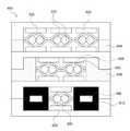
도 1은 본 발명에 따른 케이블류 보호장치에 관한 하나의 실시예를 개략적으로 도시한 것이다.
도 2는 도 1에 도시된 케이블류 보호장치에서 다중 슬리브에 케이블류 및 가이드 체인이 삽입된 모습에 관한 하나의 실시예를 개략적으로 도시한 것이다.
도 3은 도 1에서 A-A' 단면의 구조를 개략적으로 도시한 것이다.
도 4는 본 발명에 따른 다중 슬리브가 복층인 경우 클램프의 단면 구조를 개략적으로 도시한 것이다.
도 5는 본 발명에 따른 케이블류 보호장치용 다중 슬리브에 관한 하나의 실시예의 단면 구조 및 제조방법을 개략적으로 도시한 것이다.
도 6는 도 5에서 이점 실선으로 구획된 부분을 확대 도시한 것이다.BRIEF DESCRIPTION OF THE DRAWINGS FIG. 1 schematically shows one embodiment of a cable-current protection device according to the present invention. FIG.
Fig. 2 is a schematic view of one embodiment of a cable flow guiding device shown in Fig. 1 in which cables and a guide chain are inserted into multiple sleeves. Fig.
FIG. 3 schematically shows the structure of a section AA 'in FIG.
4 schematically shows a cross-sectional structure of a clamp when the multiple sleeves according to the present invention are multi-layered.
5 schematically shows a cross-sectional structure and a manufacturing method of one embodiment of a multiple sleeve for a cable-current protection device according to the present invention.
FIG. 6 is an enlarged view of a portion divided by a solid line in FIG.
이하, 본 발명의 바람직한 실시예들을 상세히 설명하기로 한다. 그러나, 본 발명은 여기서 설명된 실시예들에 한정되지 않고 다른 형태로 구체화될 수도 있다. 오히려, 여기서 소개되는 실시예들은 개시된 내용이 철저하고 완전해질 수 있도록, 그리고 당업자에게 본 발명의 사상이 충분히 전달될 수 있도록 하기 위해 제공되어지는 것이다. 명세서 전체에 걸쳐서 동일한 참조번호들은 동일한 구성요소들을 나타낸다.Hereinafter, preferred embodiments of the present invention will be described in detail. However, the present invention is not limited to the embodiments described herein but may be embodied in other forms. Rather, the embodiments disclosed herein are provided so that this disclosure will be thorough and complete, and will fully convey the concept of the invention to those skilled in the art. Like reference numerals designate like elements throughout the specification.
도 1은 본 발명에 따른 케이블류 보호장치에 관한 하나의 실시예를 개략적으로 도시한 것이고, 도 2는 도 1에 도시된 케이블류 보호장치에서 다중 슬리브에 케이블류 및 가이드 체인이 삽입된 모습에 관한 하나의 실시예를 개략적으로 도시한 것이며, 도 3은 도 1에서 A-A' 단면의 구조를 개략적으로 도시한 것이고, 도 4는 본 발명에 따른 다중 슬리브가 복층인 경우 클램프의 단면 구조를 개략적으로 도시한 것이다.FIG. 1 schematically shows one embodiment of a cable guiding device according to the present invention, and FIG. 2 is a view showing a cable guiding device shown in FIG. 1 in which cables and guide chains are inserted into multiple sleeves FIG. 3 schematically illustrates the structure of a section AA 'in FIG. 1, and FIG. 4 schematically illustrates a cross-sectional structure of a clamp when the multisleeve according to the present invention is a multi-layer structure Respectively.
도 1 및 2에 도시된 바와 같이, 본 발명에 따른 케이블류 보호장치는 하나 이상의 케이블류(200), 가이드 체인(100), 유체 공급호스(미도시) 등이 삽입되어 수용될 수 있는 하나 이상의 포드(pod)(530)를 포함하는 가요성 다중 슬리브(500), 상기 가요성 다중 슬리브(500)의 하나 이상의 포드(530), 바람직하게는 최외곽에 배치된 하나 이상의 포드(530)에 삽입되어 수용되는 가이드 체인(100), 및 상기 가요성 다중 슬리브(500)의 양 말단에 배치되어 상기 포드(530)의 양 말단을 고정하고 실링(sealing)하는 클램프(600)를 포함할 수 있다.1 and 2, a cable guiding device according to the present invention includes at least one
상기 가이드 체인(100)은 상기 가요성 다중 슬리브의 하나 이상의 포드(530), 바람직하게는 최외각 포드(530)에 삽입되어 상기 가요성 다중 슬리브의 직선 부분에서 자중에 의한 처짐을 방지하고, 굴곡 부분에서의 일정한 곡률 반경을 유지하는 기능을 수행할 수 있고, 금속, 플라스틱 등의 소재로 이루어질 수 있다.The
그리고, 상기 클램프(600)는 상기 포드(530) 내면과 이에 삽입되는 케이블류(200)와의 마찰에 의해 발생하는 분진이 외부로 배출되는 것을 억제할 수 있어, 반도체 웨이어 같은 초정밀 및 고순도 제품의 생산공정에서 사용하기에 적합하다.The
또한, 도 3에 도시된 바와 같이, 상기 클램프(600)는 가이드 체인(100)을 상기 클램프에 연결하며 가이드 체인(100)이 삽입된 포드의 말단을 실링하는 엔드캡(610), 다중 슬리브(500)가 클램프 내부에서 빠지는 것을 방지하기 위해 다중 슬리브(500)의 미끄러짐을 방지하는 슬립방지 패드(620) 등을 추가로 포함할 수 있다. 여기서, 슬립방지 패드(620)는 케이블을 보호하기 위해 연질 고무 재질로 이루어질 수 있고, 미끄럼 방지를 위해 바닥면은 널링(knurling) 처리가 될 수 있다.3, the
나아가, 도 4에 도시된 바와 같이, 본 발명에 따른 다중 슬리브는 포드(530) 갯수가 동일하거나 상이한 2개 이상의 다중 슬리브가 적층된 복층의 구조로 사용될 수 있고, 이러한 경우 복층의 다중 슬리브 말단에 적용되는 클램프(600) 역시 복층으로 형성될 수 있다. 복층의 다중 슬리브에 적용되는 클램프(600)는 포드(530) 갯수가 상대적으로 작은 다중 슬리브의 측면 빈 공간을 메우는 이너블록(630), 다중 슬리브가 삽입되는 공간을 확보하기 위해 하층 클램프와 상층 클램프 사이에 삽입되는 스페이서(640) 등을 추가로 포함할 수 있다.4, the multiple sleeves according to the present invention can be used in a multi-layered structure in which two or more multi-sleeves having the same or different number of
도 5는 본 발명에 따른 케이블류 보호장치용 다중 슬리브에 관한 하나의 실시예의 단면 구조 및 제조방법을 개략적으로 도시한 것이고, 도 6는 도 5에서 이점 실선으로 구획된 부분을 확대 도시한 것이다.FIG. 5 schematically shows a cross-sectional structure and a manufacturing method of one embodiment of a multiple sleeve for a cable-current protection device according to the present invention, and FIG. 6 is an enlarged view of a portion partitioned by the advantageous solid line in FIG.
도 5에 도시된 바와 같이, 본 발명에 따른 다중 슬리브(500)는 상부 가요성 부재(510) 및 하부 가요성 부재(520)의 부분적 접합에 의해 형성될 수 있고, 상기 상부 가요성 부재(510) 및 상기 하부 가요성 부재(520)의 접합부들 사이의 접합되지 않는 부분에 의해 포드(530)가 형성될 수 있으며, 여기서 상기 상부 가요성 부재(510)는 폴리우레탄 등의 가요성 수지로 이루어지며 상기 다중 슬리브의 반복적인 굴곡 이동시에 작용하는 응력을 완화시켜 주는 신축층(511)의 상부 및 하부 표면 각각에 불소수지 등의 내마모성, 윤활성 등이 우수하고 마찰계수가 낮은 수지로 이루어진 내마모층(512,512')이 핫멜트 등의 접착 조성물로부터 형성된 접착층(513)에 의해 접합됨으로써 형성될 수 있으며, 상기 하부 가요성 부재(520)는 상기 상부 가요성 부재(520)와 대칭되는 구조로 적층될 수 있다.5, the
또한, 상기 가요성 부재(510,520) 각각에 포함된 내마모층(512,512',522,522') 중 포드(pod)(530)의 내면을 형성하는 내마모층(512',522')은 동일하거나 상이한 길이의 간격으로 이격된 복수개의 내마모층 컬럼을 포함할 수 있고, 상기 복수개의 내마모층(512',522') 컬럼 중 좌측 및 우측의 최외측 내마모층 컬럼은 이들의 외측 말단 각각이 상기 다중 슬리브(500)의 좌측 및 우측 말단의 외곽선으로부터 동일하거나 상이한 길이의 간격으로 이격될 수 있다.The wear
도 3 및 4에 도시된 바와 같이, 상기 복수개의 내마모층(512,522') 컬럼 사이 및 말단에 형성된 간격을 통해 용출되는 핫멜트 등의 접착 조성물이 서로 열융착 등에 의해 접합됨으로써 상부 가요성 부재(510)와 하부 가요성 부재(520)가 국소적으로 접합되고, 접합부들 사이의 접합되지 않는 부분에 의해 케이블류가 삽입될 수 있는 하나 이상의 포드(pod)(530)가 형성될 수 있다.As shown in FIGS. 3 and 4, adhesive compositions such as hot melts, which are eluted through spaces formed between the columns of the abrasion
상기 포드(530)의 내면은 내마모성, 윤활성 등이 우수하고 마찰계수가 낮은 수지로 이루어진 내마모층(512',522')으로 이루어져 있기 때문에, 상기 포드(530)에 삽입되어 수용되는 케이블류 등과의 마찰에 의해 상기 케이블류가 손상되는 것을 회피하거나 최소화할 수 있고, 케이블류를 포드에 용이하게 삽입할 수 있게 함으로써 상기 케이블류를 보호할 수 있다.Since the inner surface of the
구체적으로, 각각 적층 형성된 상부 가요성 부재(510) 및 하부 가요성 부재(520)를 이들 각각의 접착층(513,523)에 포함된 핫멜트 등의 접착 조성물의 열융착에 의해 국소적으로 접합시킬 때, 접합되는 부분은 고온 및 고압에서 상기 핫멜트 등의 접착 조성물이 열융착될 수 있고, 바람직하게는 상기 접합되는 부분에서 상기 접착 조성물로부터 형성되는 접착층(513,523)과 함께 상기 신축층(511,521)도 용융되어 접합됨으로써 접합강도가 추가로 향상될 수 있고, 상기 접착층(513,523) 및 상기 신축층(511,521)이 모두 동일한 우레탄계 소재로 이루어지는 경우 접합력이 추가로 향상될 수 있다.Concretely, when the upper and lower
상기 접합되는 부분은 예를 들어 120 내지 190℃로 가열된 한 쌍의 롤러 사이를 통과하면서 2 내지 5 MPa의 가압 상태에서 상기 핫멜트 등의 접착 조성물이 1차 열융착된 후, 70 내지 110℃로 가열된 한 쌍의 롤러 사이를 통과하면서 2 내지 5 MPa의 가압 상태에서 상기 핫멜트 등의 접착 조성물이 2차 열융착될 수 있다. 여기서, 상기 2차 열융착은 1차 열융착에 의해 접합된 부분의 접합 강도를 향상시키고 1차 열융착시 발생한 표면 주름 등을 제거하기 위해 추가로 수행될 수 있는 것이다.The bonded portion is passed through a pair of rollers heated to, for example, 120 to 190 DEG C while being thermally fused with the adhesive composition such as the hot melt under a pressure of 2 to 5 MPa, The adhesive composition such as the hot melt can be thermally fused at a pressure of 2 to 5 MPa while passing between the heated pair of rollers. Here, the secondary thermal welding may be further performed to improve the bonding strength of the jointed portion by primary heat welding and to remove the surface wrinkles or the like that are generated during the primary heat welding.
특히, 상기 내마모층(512',522')은 아래 수학식 1의 조건을 만족할 수 있다.In particular, the wear
[수학식 1][Equation 1]
y=ax+0.15[bd+1]±0.15y = ax + 0.15 [bd + 1] + 0.15
상기 수학식 1에서,In the above equation (1)
d는 임의의 포드(pod)(530)에 삽입되는 케이블류의 최대 단면적과 동일한 단면적을 갖는 원의 직경(mm)이고,d is the diameter (mm) of the circle having the same cross-sectional area as the maximum cross-sectional area of the cable flow inserted in any
x는 상기 포드(pod)를 형성하는 내마모층(512',522') 컬럼의 폭 길이(mm)이고,x is the width in mm of the column of abrasion
y는 상기 내마모층 컬럼과 인전합 다른 내마모층 컬럼 사이의 간격 또는 최외곽 내마모층 컬럼 말단의 간격(mm)이고,y is an interval between the wear resistant layer column and another wear resistant layer column or the interval (mm) between the end portions of the wear resistant layer of the outermost wearable layer,
a는 0.08 내지 0.12이고,a is from 0.08 to 0.12,
b는 0.09 내지 0.10이다.b is 0.09 to 0.10.
참고로, 상기 수학식 1에서 [bd+1]은 가우스 함수로서 bd+1의 소수를 버린 정수를 의미한다.For reference, [bd + 1] in the above equation (1) means an integer which is a Gaussian function and has a prime of bd + 1 discarded.
본 발명자들은 상기 내마모층(512',522')이 상기 수학식 1의 조건을 벗어나는 경우, 즉 임의의 포드(530)에 삽입되는 케이블류의 단면적에 따른 상기 포드(pod)를 형성하는 하나의 내마모층(512',522') 컬럼의 폭 길이(x) 및/또는 상기 내마모층 컬럼과 인접한 다른 내마모층 컬럼 사이의 간격 또는 최외곽 내마모층 컬럼 말단의 간격(y)이 기준 미달인 경우, 본 발명에 따른 케이블류 보호장치용 다중 슬리브는 내구성이 크게 저하, 특히 상부 가요성 부재와 하부 가요성 부재의 접합부의 내구성이 크게 저하되기 때문에 반복적으로 굴곡이동할 때 상기 접합부가 국소적으로 손상될 수 있고, 상기 손상된 접합부에서 상부 가요성 부재와 하부 가요성 부재 사이에 틈이 형성될 수 있음을 실험적으로 확인함으로써 본 발명을 완성하였고, 상기 틈을 통해 상기 포드(530) 내부의 분진 등이 외부로 유출되어 초정밀 및 고순도 제품의 생산공정에서의 공정 오류를 유발하거나 복수개의 포드(530)에 각각 삽입되고 인접한 케이블류들이 서로 마찰에 의해 손상될 수 있다.The present inventors have found that when the abrasion
한편, 본 발명에 따른 케이블류 보호장치용 다중 슬리브에 있어서, 복수개의 포드(530) 각각은 서로 상이한 단면적의 케이블류가 삽입될 수 있으므로, 수학식 1의 조건을 만족함을 전제로 각각의 포드(530)에 삽입되는 케이블류의 단면적에 따라 서로 상이한 x 및/또는 y, 즉 상기 포드(pod)를 형성하는 내마모층(512',522') 컬럼의 폭 길이(x) 및/또는 상기 내마모층 컬럼과 인전합 다른 내마모층 컬럼 사이의 간격 또는 최외곽 내마모층 컬럼 말단의 간격(y)을 보유할 수 있다.In the multiple sleeves for the cable guiding device according to the present invention, since each of the plurality of
예를 들어, 임의의 포드(pod)(530)에 삽입되는 케이블류의 최대 단면적과 동일한 단면적을 갖는 원의 직경(d)은 3.8 내지 10.0 mm, 상기 포드(pod)를 형성하는 내마모층(512',522') 컬럼의 폭 길이(x)는 15 내지 23 mm, 상기 내마모층 컬럼과 인전합 다른 내마모층 컬럼 사이의 간격 또는 최외곽 내마모층 컬럼 말단의 간격(y)은 1.5 내지 2.5 mm일 수 있고, 나아가 상기 신축층(511,521)의 두께는 0.2 내지 0.4 mm, 내마모층(512,512',522,522')의 두께는 0.05 내지 0.15 mm, 상기 접착층(513,523)의 두께는 0.025 내지 0.075 mm일 수 있다.For example, the diameter d of the circle having the same cross-sectional area as the largest cross-sectional area of the cable flow inserted in any
상기 내마모층(512,512',522,522')은 내마모성, 윤활성 등이 우수하고 마찰계수가 낮기 때문에, 상기 포드(530)의 내면에 배치되는 경우 상기 포드(530)에 삽입되어 수용되는 케이블류 등과의 마찰에 의해 손상되는 것을 회피하거나 억제하는 동시에 상기 마찰에 의한 분진 발생을 억제할 수 있는 한편, 상기 포드(530)의 외면에 배치되는 경우 상기 가요성 다중 슬리브(500) 사이의 마찰에 의해 손상되는 것을 회피하거나 억제하는 동시에 상기 마찰에 의한 분진 발생을 억제할 수 있다.Since the abrasion
상기 내마모층(512,512',522,522')을 형성하는 수지는 예를 들어 폴리테트라플루오로에틸렌(PTFE), 플로오로에틸렌프로필렌(FEP), 폴리플루오로알콕시(PFA) 등으로부터 선택될 수 있고, 바람직하게는 폴리테트라플루오로에틸렌(PTFE), 더욱 바람직하게는 팽창 폴리테트라플루오로에틸렌(ePTFE)일 수 있다.The resin forming the abrasion
상기 팽창 폴리테트라플루오로에틸렌(ePTFE)은 작은 단위체들을 사슬 혹은 그물 형태로 화학결합하여 만드는 고분자소재로서 미세기공이 형성되어 있는 다공성 구조로 이루어져 있으며, 내열성, 내화학성이 뛰어나고 마찰계수가 매우 낮다. 특히 모든 화학약품에 대해 내화학성이 있으며, 표면이 매끄럽고 넓은 온도범위에서 물리적 특성이 유지될 수 있다.The expanded polytetrafluoroethylene (ePTFE) is a polymer material formed by chemical bonding of small units in a chain or net form. The porous polytetrafluoroethylene (ePTFE) is formed of a porous structure in which micropores are formed, and has excellent heat resistance, chemical resistance and very low friction coefficient. In particular, it is chemically resistant to all chemicals, and its surface is smooth and its physical properties can be maintained over a wide temperature range.
그러나, 상기 팽창 폴리테트라플루오로에틸렌(ePTFE)은 (-)전하로 대전되려는 성향이 강하여 정전기 발생이 쉽기 때문에 공기중의 분진이 상기 내마모층(512,522)에 달라붙거나 발생된 정전기가 공기 중에서 방전되어 공정 오류 등을 유발하거나 상기 포드(530)에 삽입되는 케이블의 신호 또는 제어 오류를 유발할 수 있다.However, since the expanded polytetrafluoroethylene (ePTFE) has a strong tendency to be charged with a negative charge, static electricity is easily generated, so that dust in the air sticks to the abrasion
따라서, 상기 내마모층(512,512',522,522'), 특히 상기 포드(530)의 외면에 배치된 내마모층(512,522)은 대전방지처리가 될 수 있다. 상기 대전방지처리는 상기 가요성 다중 슬리브(500)의 소재를 대전방지제에 침지하거나 상기 가요성 다중 슬리브(500)의 표면에 대전방지제를 분무하는 형태로 수행될 수 있다.Therefore, the wear
상기 대전방지제는 전도성 나노 카본 또는 금속이나 전도성 폴리머 또는 이오노머 등의 양전하 또는 음전하를 띄는 대전 방지 입자, 상기 대전 방지 입자가 분산된 용매, 상기 입자의 분산을 용이하게 하는 계면활성제 등을 포함할 수 있다.The antistatic agent may include antistatic particles having a positive or negative charge such as a conductive nanocarbon or a metal, a conductive polymer, or an ionomer, a solvent in which the antistatic particles are dispersed, a surfactant that facilitates dispersion of the particles, and the like .
여기서, 상기 전도성 폴리머 또는 이오노머는 폴리아세틸렌, 폴리피롤, 폴리티오펜, 폴리페닐렌, 폴리페닐렌설파이드, 폴리아닐린 등으로부터 선택될 수 있고, 바람직하게는 플루오르화 입자를 포함하는 전도성 폴리머 또는 이오노머일 수 있다. 또한, 상기 용매는 아크릴레이트 같은 아크릴계 용매, 이소프로필알콜 같은 알콜계 용매 등의 용매일 수 있다.Here, the conductive polymer or ionomer may be selected from polyacetylene, polypyrrole, polythiophene, polyphenylene, polyphenylene sulfide, polyaniline, and the like, preferably a conductive polymer or ionomer including fluorinated particles . The solvent may be an acrylic solvent such as acrylate or an alcohol solvent such as isopropyl alcohol.
상기 대전방지제가 상기 내마모층의 미세기공에 스며든 후 상기 대전방지제 내의 용매는 휘발되고, 상기 양전하 또는 음전하를 띄는 대전 방지 입자는 상기 내마모층을 구성하는 팽창 폴리테트라플루오로에틸렌(ePTFE)의 미세기공에 잔류함으로써 상기 팽창 폴리테트라플루오로에틸렌(ePTFE)의 대전성을 현저히 낮출 수 있다.After the antistatic agent has permeated into the micropores of the wear resistant layer, the solvent in the antistatic agent is volatilized, and the antistatic particles having a positive charge or a negatively charged property are expanded polytetrafluoroethylene (ePTFE) constituting the wear resistant layer, The chargeability of the expanded polytetrafluoroethylene (ePTFE) can be remarkably lowered.
또한, 상기 양전하 또는 음전하를 띄는 입자는 상기 내마모층(512,512',522,522')의 표면에 잔존하는 것이 아니라 내부의 미세 그물망 형태의 조직에도 증착되기 때문에, 상기 내마모층(512,512',522,522') 사이의 마찰에 의해서 제거되지 않고 상기 내마모층(512,512',522,522')의 물성을 저하시키기 않으면서 안정적으로 대전방지 기능을 수행할 수 있다.In addition, since the positively or negatively charged particles do not remain on the surface of the abrasion
상기 접착층(513,523)에 포함되는 핫멜트는 앞서 기술한 조건의 열융착에 의해 접합될 수 있다면 특별히 제한되지 않고, 예를 들어, 폴리우레탄계, 열가소성 폴리우레탄계, 폴리에테르설폰계, 폴리아미드계, 에틸렌비닐아세테이트계 핫멜트를 적용할 수 있다.The hot melts contained in the
[실시예][Example]
아래 표 1에 나타난 바와 같은 사양의 다중 슬리브를 제조 후 이의 일 말단을 클램프로 실링하고 타 말단을 통해 모든 포드 내로 동시에 공기를 주입하여 상부 가요성 부재와 하부 가요성 부재의 접합부가 견디지 못하고 국소적으로 터지는 시점의 공기압을 측정했다. 측정 결과는 아래 표 1에 나타난 바와 같다.After manufacturing multiple sleeves with specifications as shown in Table 1 below, one end thereof is sealed with a clamp, and air is simultaneously injected into all the pods through the other end, so that the joints of the upper flexible member and the lower flexible member can not stand, Was measured. The measurement results are shown in Table 1 below.
상기 표 1에 나타난 바와 같이, 본 발명에 따른 케이블류 보호장치용 다중 슬리브는 상부 가요성 부재와 하부 가요성 부재의 접합부의 내구성이 우수하여 높은 내부 압력에서도 상기 접합부가 손상되지 않는 것으로 확인되었고, 이로써 1000만회 이상의 반복적인 굴곡 이동시에도 상기 접합부가 손상되지 않기 때문에, 상기 접합부의 손상에 의해 발생한 틈을 통해 포드 내부의 분진이 외부로 유출되어 초정밀 및 고순도 제품의 생산공정에서의 공정 오류를 유발하거나 복수개의 포드에 각각 삽입되고 인접한 케이블류들이 서로 마찰에 의해 손상되는 것을 방지할 수 있다.As shown in Table 1, it was confirmed that the multi-sleeves for the cable-guiding device according to the present invention had excellent durability of the joints of the upper flexible member and the lower flexible member so that the joints were not damaged even at a high internal pressure, Accordingly, the joint is not damaged even when it is repeatedly bending over 10 million times. Therefore, the dust inside the pod flows out to the outside through the gap created by the damage of the joint to cause a process error in the production process of the ultra-precise and high- It is possible to prevent the adjacent cable streams inserted into the plurality of pods from being damaged by friction with each other.
본 명세서는 본 발명의 바람직한 실시예를 참조하여 설명하였지만, 해당 기술분야의 당업자는 이하에서 서술하는 특허청구범위에 기재된 본 발명의 사상 및 영역으로부터 벗어나지 않는 범위 내에서 본 발명을 다양하게 수정 및 변경 실시할 수 있을 것이다. 그러므로 변형된 실시가 기본적으로 본 발명의 특허청구범위의 구성요소를 포함한다면 모두 본 발명의 기술적 범주에 포함된다고 보아야 한다.While the present invention has been particularly shown and described with reference to preferred embodiments thereof, it will be understood by those skilled in the art that various changes and modifications may be made without departing from the spirit and scope of the invention as defined in the following claims. . It is therefore to be understood that the modified embodiments are included in the technical scope of the present invention if they basically include elements of the claims of the present invention.
100 : 가이드 체인 200 : 케이블류
500 : 가요성 다중 슬리브 600 : 클램프100: Guide chain 200: Cables
500: flexible multi-sleeve 600: clamp
Claims (12)
Translated fromKorean상기 다중 슬리브는 상부 가요성 부재 및 하부 가요성 부재의 부분적 접합에 의해 형성되고,
상기 포드는 상기 상부 가요성 부재와 상기 하부 가요성 부재의 접합부들 사이의 접합되지 않는 부분에 의해 형성되며,
상기 상부 가요성 부재는 가요성 수지로 이루어진 신축층, 상기 신축층의 상부 및 하부 표면 각각에 배치되고 폴리테트라플루오로에틸렌(PTFE), 팽창 폴리테트라플루오로에틸렌(ePTFE), 플로오로에틸렌프로필렌(FEP) 및 폴리플루오로알콕시(PFA)로 이루어진 그룹으로부터 선택된 1종 이상의 수지로 이루어진 내마모층, 상기 신축층과 상기 내마모층 사이에서 이들을 서로 접합시키는 접착 조성물에 의해 형성된 접착층을 포함하고,
상기 내마모층 중 상기 신축층의 하부 표면에 배치되어 상기 포드의 내면을 형성하는 내마모층은 동일하거나 상이한 길이의 간격으로 이격되는 복수개의 내마모층 컬럼을 포함하고, 상기 복수개의 내마모층 컬럼 중 좌측 및 우측의 최외측 내마모층 컬럼은 이들의 외측 말단 각각이 상기 다중 슬리브의 좌측 및 우측 말단의 외곽선으로부터 동일하거나 상이한 길이의 간격으로 이격되어 있으며,
상기 하부 가요성 부재는 상기 상부 가요성 부재와 대칭되는 적층 구조를 갖고,
상기 상부 가요성 부재에 포함된 내마모층 컬럼 사이 및 말단에 형성된 간격과 상기 하부 가요성 부재에 포함된 내마모층 컬럼 사이 및 말단에 형성된 간격을 통해 각각 유출되는 접착 조성물이 서로 접합됨으로써 상기 접합부가 형성되는, 다중 슬리브.A multislice for a cable current protection device comprising at least one pod into which a cable, fluid supply hose or guide chain can be inserted and received,
The multiple sleeves being formed by partial joining of the upper and lower flexible members,
The pod being formed by the unbonded portion between the joining portions of the upper and lower flexible members,
The upper flexible member is disposed on each of the upper and lower surfaces of the elastic layer. The upper flexible member is made of polytetrafluoroethylene (PTFE), expanded polytetrafluoroethylene (ePTFE), fluoroethylene propylene ( FEP) and polyfluoroalkoxy (PFA), and an adhesive layer formed by a bonding composition for bonding these between the elastic layer and the abrasion resistant layer,
Wherein the wear-resistant layer disposed on the lower surface of the elastic layer and forming the inner surface of the pod includes a plurality of wear-resistant layer columns spaced at equal or different lengths of the wear-resistant layer, The leftmost and rightmost outermost abrasion-resistant layer columns are spaced apart from each other at their outer ends by the same or different lengths from the outline of the left and right ends of the multiple sleeves,
Wherein the lower flexible member has a laminated structure symmetrical with the upper flexible member,
The adhesive composition flowing out through the gap formed between the end portions of the wear resistant layer and the end of the wear resistant layer included in the upper flexible member and the gap formed between the ends of the wear resistant layer included in the lower flexible member are bonded to each other, Is formed.
상기 포드의 내면을 형성하는 내마모층은 아래 수학식 1의 조건을 만족하는 것을 특징으로 하는, 다중 슬리브.
[수학식 1]
y=ax+0.15[bd+1]±0.15
상기 수학식 1에서,
d는 임의의 포드에 삽입되는 케이블류의 최대 단면적과 동일한 단면적을 갖는 원의 직경(mm)이고,
x는 상기 포드를 형성하는 내마모층 컬럼의 폭 길이(mm)이고,
y는 상기 내마모층 컬럼과 인접한 다른 내마모층 컬럼 사이의 간격 또는 최외곽 내마모층 컬럼 말단의 간격(mm)이고,
a는 0.08 내지 0.12이고,
b는 0.09 내지 0.10이다.The method according to claim 1,
Wherein the abrasion resistant layer forming the inner surface of the pod satisfies the following condition (1).
[Equation 1]
y = ax + 0.15 [bd + 1] + 0.15
In the above equation (1)
d is the diameter (mm) of the circle having the same cross-sectional area as the maximum cross-sectional area of the cable streams inserted in an arbitrary pod,
x is the width (mm) of the width of the wear resistant layer forming the pod,
y is the distance between said abrasion-resistant layer column and adjacent abrasion-resistant layer columns, or the distance (mm) between the outermost abrasive layer column ends,
a is from 0.08 to 0.12,
b is 0.09 to 0.10.
상기 포드에 삽입되는 케이블류의 최대 단면적과 동일한 단면적을 갖는 원의 직경(d)은 3.8 내지 10.0 mm, 상기 포드를 형성하는 내마모층 컬럼의 폭 길이(x)는 15 내지 23 mm, 상기 내마모층 컬럼과 인전합 다른 내마모층 컬럼 사이의 간격 또는 최외곽 내마모층 컬럼 말단의 간격(y)은 1.5 내지 2.5 mm인 것을 특징으로 하는, 다중 슬리브.3. The method of claim 2,
The diameter d of the circle having the same cross-sectional area as the maximum cross-sectional area of the claws inserted into the pod is 3.8 to 10.0 mm, the width x of the abrasion-resistant layer forming the pod is 15 to 23 mm, Characterized in that the spacing (y) between the abrasive layer column and the other abrasive layer column or between the abrasive layer edges of the outermost abrasive layer is 1.5 to 2.5 mm.
상기 신축층의 두께는 0.2 내지 0.4 mm, 내마모층의 두께는 0.05 내지 0.15 mm, 상기 접착층의 두께는 0.025 내지 0.075 mm인 것을 특징으로 하는, 다중 슬리브.4. The method according to any one of claims 1 to 3,
Wherein the thickness of the elastic layer is 0.2 to 0.4 mm, the thickness of the wear resistant layer is 0.05 to 0.15 mm, and the thickness of the adhesive layer is 0.025 to 0.075 mm.
상기 신축층은 폴리우레탄 수지를 포함하는 것을 특징으로 하는, 다중 슬리브.4. The method according to any one of claims 1 to 3,
Wherein the elastic layer comprises a polyurethane resin.
상기 내마모층은 팽창 폴리테트라플루오로에틸렌(ePTFE) 수지를 포함하는 것을 특징으로 하는, 다중 슬리브.4. The method according to any one of claims 1 to 3,
Characterized in that the abrasion resistant layer comprises an expanded polytetrafluoroethylene (ePTFE) resin.
상기 접착 조성물은 핫멜트를 포함하는 것을 특징으로 하는, 다중 슬리브.4. The method according to any one of claims 1 to 3,
Characterized in that the adhesive composition comprises a hot melt.
적어도 하나의 상기 내마모층은 복수의 미세기공이 형성된 다공성 수지를 포함하고, 상기 복수의 미세기공 중 적어도 일부에 대전 방지 입자가 포함되는 것을 특징으로 하는, 다중 슬리브.4. The method according to any one of claims 1 to 3,
Wherein at least one abrasion resistant layer comprises a porous resin having a plurality of micropores formed therein, and at least a part of the plurality of micropores includes antistatic particles.
상기 대전 방지 입자는 전도성 나노 카본, 전도성 나노 금속, 전도성 폴리머 및 이오노머로 이루어진 그룹으로부터 선택된 1종 이상의 양전하 또는 음전하를 띄는 입자를 포함하는 것을 특징으로 하는, 다중 슬리브.9. The method of claim 8,
Wherein the antistatic particles comprise at least one positively charged or negatively charged particle selected from the group consisting of a conductive nanocarbon, a conductive nanometal, a conductive polymer and an ionomer.
적어도 하나의 상기 내마모층은 작은 단위체들이 사슬 혹은 그물 형태로 결합되어 미세 그물망 형태로 형성된 고분자 수지를 포함하고, 상기 미세 그물망 형태의 조직에 대전 방지 입자가 붙어 있는 것을 특징으로 하는, 다중 슬리브.4. The method according to any one of claims 1 to 3,
Characterized in that at least one abrasion resistant layer comprises a polymeric resin in which small units are joined in a chain or net form to form a microgranular net, and wherein the microgranular net tissue is adhered with antistatic particles.
상기 접합부에서 상기 접착층과 상기 신축층이 모두 용융되어 접합되는 것을 특징으로 하는, 다중 슬리브.4. The method according to any one of claims 1 to 3,
And the adhesive layer and the elastic layer are both melted and bonded at the joint portion.
상기 다중 슬리브의 하나 이상의 포드에 삽입되어 수용되는 가이드 체인; 및
상기 다중 슬리브의 양 말단에 배치되어 상기 포드의 양 말단을 고정하고 실링하는 클램프를 포함하는, 케이블류 보호장치.6. A multi-sleeve according to any one of claims 1 to 3,
A guide chain inserted and received in one or more pods of the multiple sleeves; And
And a clamp disposed at both ends of the multiple sleeves for securing and sealing both ends of the pod.
Priority Applications (3)
| Application Number | Priority Date | Filing Date | Title |
|---|---|---|---|
| CN201780031917.XACN109219910B (en) | 2016-05-26 | 2017-04-21 | Multiple casings for cable protection devices and cable protection devices including the same |
| JP2018554571AJP6640380B2 (en) | 2016-05-26 | 2017-04-21 | Multiple sleeve for cable protection device and cable protection device including the same |
| PCT/KR2017/004274WO2017204467A1 (en) | 2016-05-26 | 2017-04-21 | Multi-sleeve for cable protection device and cable protection device including same |
Applications Claiming Priority (2)
| Application Number | Priority Date | Filing Date | Title |
|---|---|---|---|
| KR1020160064690 | 2016-05-26 | ||
| KR20160064690 | 2016-05-26 |
Publications (2)
| Publication Number | Publication Date |
|---|---|
| KR20170134155A KR20170134155A (en) | 2017-12-06 |
| KR101890986B1true KR101890986B1 (en) | 2018-08-23 |
Family
ID=60922741
Family Applications (1)
| Application Number | Title | Priority Date | Filing Date |
|---|---|---|---|
| KR1020160103742AActiveKR101890986B1 (en) | 2016-05-26 | 2016-08-16 | Multi sleeve for cables support apparatus and cables support apparatus comprising the same |
Country Status (3)
| Country | Link |
|---|---|
| JP (1) | JP6640380B2 (en) |
| KR (1) | KR101890986B1 (en) |
| CN (1) | CN109219910B (en) |
Cited By (1)
| Publication number | Priority date | Publication date | Assignee | Title |
|---|---|---|---|---|
| WO2022102826A1 (en)* | 2020-11-16 | 2022-05-19 | 주식회사 성엔지니어링 | Dust-free cable protective cover including ultra-high molecular weight polyethylene film, and method for manufacturing same |
Families Citing this family (14)
| Publication number | Priority date | Publication date | Assignee | Title |
|---|---|---|---|---|
| JP6830040B2 (en)* | 2017-06-21 | 2021-02-17 | 大電株式会社 | Cable covers, cables, and how to manufacture them |
| CN108551132B (en)* | 2018-03-08 | 2023-08-22 | 杭州骏跃科技有限公司 | Desktop line box that line lid can be accomodate |
| KR101977070B1 (en)* | 2018-10-05 | 2019-05-10 | 성우프로링크 주식회사 | Transmission line sleeves with improved electrostatic grounding structure |
| KR102071891B1 (en)* | 2018-10-08 | 2020-02-03 | 성우프로링크 주식회사 | Supporting module for sleeves for transmission lines |
| KR102033382B1 (en)* | 2018-10-22 | 2019-10-18 | 주식회사 루아시스템즈 | Cable jacket having hetero-finishing layer |
| KR102003433B1 (en) | 2018-12-13 | 2019-07-24 | 주식회사 토마스 케이블 | Cables of clamps that consist of jackets including air blocks |
| DE202019103276U1 (en)* | 2019-06-11 | 2020-02-20 | Igus Gmbh | Compact cable protection guide for clean room applications as well as sleeve unit and clamping device for this |
| KR101995954B1 (en)* | 2019-03-05 | 2019-07-03 | 성우프로링크 주식회사 | Supporting module for long axis transmission line sleeve |
| CN110247362B (en)* | 2019-05-10 | 2020-11-06 | 湖北海洋工程装备研究院有限公司 | Cable protection device and rotating device |
| WO2021091312A1 (en)* | 2019-11-07 | 2021-05-14 | 엘에스전선 주식회사 | Sleeve for cable protection apparatus and cable protection apparatus comprising same |
| KR102088027B1 (en)* | 2019-11-11 | 2020-03-11 | 삼원액트 주식회사 | A Pad member and A CABLES GUIDING DEVICE comprising the same |
| KR102532024B1 (en)* | 2021-06-17 | 2023-05-11 | 채성정 | clean cable assembly |
| WO2025143230A1 (en)* | 2023-12-29 | 2025-07-03 | 株式会社 潤工社 | Housing member and method for manufacturing housing member |
| CN119039642B (en)* | 2024-09-27 | 2025-02-07 | 安徽省众望科希盟科技有限公司 | A wear-resistant drag chain protective material and its preparation method and application |
Citations (2)
| Publication number | Priority date | Publication date | Assignee | Title |
|---|---|---|---|---|
| KR101539311B1 (en) | 2009-03-25 | 2015-07-24 | 다이덴 가부시키가이샤 | Elongated structure for movable sections |
| KR101585900B1 (en) | 2015-06-02 | 2016-01-15 | 성문규 | Flat Cable and Manufacturing Method of it |
Family Cites Families (10)
| Publication number | Priority date | Publication date | Assignee | Title |
|---|---|---|---|---|
| JPH0343240A (en)* | 1989-07-12 | 1991-02-25 | Hitachi Cable Ltd | Metal laminated tape and electric wire using the same |
| US6571833B1 (en)* | 2000-07-14 | 2003-06-03 | Milliken & Company | Optic cable conduit insert and method of manufacture |
| JP4368886B2 (en)* | 2006-11-27 | 2009-11-18 | 株式会社椿本チエイン | Sealed cable protection guide device |
| DE102007021505A1 (en)* | 2007-05-04 | 2008-11-06 | Tesa Ag | Heat-reflecting adhesive tape with high abrasion protection |
| WO2010148165A2 (en)* | 2009-06-19 | 2010-12-23 | 3M Innovative Properties Company | Shielded electrical cable |
| ES2456354T3 (en)* | 2009-08-05 | 2014-04-22 | Prysmian S.P.A. | Flat power cable |
| CA2809044A1 (en)* | 2010-08-31 | 2012-03-08 | 3M Innovative Properties Company | Shielded electrical cable |
| JP5414704B2 (en)* | 2011-01-21 | 2014-02-12 | 株式会社椿本チエイン | Articulated cable protection guide device |
| JP5079894B2 (en)* | 2011-02-15 | 2012-11-21 | 株式会社椿本チエイン | Articulated cable protection guide device |
| CN202339760U (en)* | 2011-10-19 | 2012-07-18 | 汤广顺 | Parallel communication cable |
- 2016
- 2016-08-16KRKR1020160103742Apatent/KR101890986B1/enactiveActive
- 2017
- 2017-04-21JPJP2018554571Apatent/JP6640380B2/enactiveActive
- 2017-04-21CNCN201780031917.XApatent/CN109219910B/enactiveActive
Patent Citations (2)
| Publication number | Priority date | Publication date | Assignee | Title |
|---|---|---|---|---|
| KR101539311B1 (en) | 2009-03-25 | 2015-07-24 | 다이덴 가부시키가이샤 | Elongated structure for movable sections |
| KR101585900B1 (en) | 2015-06-02 | 2016-01-15 | 성문규 | Flat Cable and Manufacturing Method of it |
Cited By (1)
| Publication number | Priority date | Publication date | Assignee | Title |
|---|---|---|---|---|
| WO2022102826A1 (en)* | 2020-11-16 | 2022-05-19 | 주식회사 성엔지니어링 | Dust-free cable protective cover including ultra-high molecular weight polyethylene film, and method for manufacturing same |
Also Published As
| Publication number | Publication date |
|---|---|
| CN109219910A (en) | 2019-01-15 |
| JP2019519183A (en) | 2019-07-04 |
| KR20170134155A (en) | 2017-12-06 |
| JP6640380B2 (en) | 2020-02-05 |
| CN109219910B (en) | 2020-05-19 |
Similar Documents
| Publication | Publication Date | Title |
|---|---|---|
| KR101890986B1 (en) | Multi sleeve for cables support apparatus and cables support apparatus comprising the same | |
| US10093069B2 (en) | Method of forming large diameter thermoplastic seal | |
| KR101395520B1 (en) | Mold release film for the resin encapsulation of semiconductors | |
| CN103909710B (en) | There is the laminates of fluoropolymer fabric | |
| KR101993804B1 (en) | Cable―veyor | |
| WO2017204467A1 (en) | Multi-sleeve for cable protection device and cable protection device including same | |
| CN105980130B (en) | Method of forming sealing element from extruded thermoplastic rod | |
| KR20170082103A (en) | Guide chain for cables support apparatus and cables support apparatus comprising the same | |
| US10197207B2 (en) | Conductive elastomeric flexible coupling | |
| KR102684418B1 (en) | Clamp for cables support apparatus and cables support apparatus comprising the same | |
| KR101340282B1 (en) | A hose assembly for fluid transfer and the method thereof | |
| KR20230092314A (en) | A production method of a cable covering pod | |
| JP3126448U (en) | Antistatic resin tube | |
| CN105143749A (en) | Device for protecting mechanical parts | |
| KR101946314B1 (en) | Guide roller | |
| EP0027708A1 (en) | Thermoplastic reinforced hose | |
| JP2011121689A (en) | Carrying flat belt and method of manufacturing the same | |
| WO2021091312A1 (en) | Sleeve for cable protection apparatus and cable protection apparatus comprising same | |
| KR20210065884A (en) | Cable package | |
| US20250198547A1 (en) | Tube and method for making same | |
| ES3035769T3 (en) | Hydraulic coupling device | |
| JP2012096886A (en) | Conveying belt | |
| KR20190045428A (en) | A Protection Unit for Cable Supporting and Manufacturing Method of it | |
| JP2019005997A (en) | Multilayer tube | |
| WO2025143230A1 (en) | Housing member and method for manufacturing housing member |
Legal Events
| Date | Code | Title | Description |
|---|---|---|---|
| A201 | Request for examination | ||
| PA0109 | Patent application | St.27 status event code:A-0-1-A10-A12-nap-PA0109 | |
| PA0201 | Request for examination | St.27 status event code:A-1-2-D10-D11-exm-PA0201 | |
| R17-X000 | Change to representative recorded | St.27 status event code:A-3-3-R10-R17-oth-X000 | |
| PG1501 | Laying open of application | St.27 status event code:A-1-1-Q10-Q12-nap-PG1501 | |
| E902 | Notification of reason for refusal | ||
| PE0902 | Notice of grounds for rejection | St.27 status event code:A-1-2-D10-D21-exm-PE0902 | |
| P11-X000 | Amendment of application requested | St.27 status event code:A-2-2-P10-P11-nap-X000 | |
| P13-X000 | Application amended | St.27 status event code:A-2-2-P10-P13-nap-X000 | |
| E701 | Decision to grant or registration of patent right | ||
| PE0701 | Decision of registration | St.27 status event code:A-1-2-D10-D22-exm-PE0701 | |
| PR0701 | Registration of establishment | St.27 status event code:A-2-4-F10-F11-exm-PR0701 | |
| PR1002 | Payment of registration fee | St.27 status event code:A-2-2-U10-U11-oth-PR1002 Fee payment year number:1 | |
| PG1601 | Publication of registration | St.27 status event code:A-4-4-Q10-Q13-nap-PG1601 | |
| PN2301 | Change of applicant | St.27 status event code:A-5-5-R10-R13-asn-PN2301 St.27 status event code:A-5-5-R10-R11-asn-PN2301 | |
| PR1001 | Payment of annual fee | St.27 status event code:A-4-4-U10-U11-oth-PR1001 Fee payment year number:4 | |
| PR1001 | Payment of annual fee | St.27 status event code:A-4-4-U10-U11-oth-PR1001 Fee payment year number:5 | |
| PR1001 | Payment of annual fee | St.27 status event code:A-4-4-U10-U11-oth-PR1001 Fee payment year number:6 | |
| PR1001 | Payment of annual fee | St.27 status event code:A-4-4-U10-U11-oth-PR1001 Fee payment year number:7 | |
| PR1001 | Payment of annual fee | St.27 status event code:A-4-4-U10-U11-oth-PR1001 Fee payment year number:8 |