KR101885108B1 - Apparatus for treatimg substrate - Google Patents
Apparatus for treatimg substrateDownload PDFInfo
- Publication number
- KR101885108B1 KR101885108B1KR1020110090375AKR20110090375AKR101885108B1KR 101885108 B1KR101885108 B1KR 101885108B1KR 1020110090375 AKR1020110090375 AKR 1020110090375AKR 20110090375 AKR20110090375 AKR 20110090375AKR 101885108 B1KR101885108 B1KR 101885108B1
- Authority
- KR
- South Korea
- Prior art keywords
- gas
- ring
- substrate
- excitation space
- groove
- Prior art date
- Legal status (The legal status is an assumption and is not a legal conclusion. Google has not performed a legal analysis and makes no representation as to the accuracy of the status listed.)
- Active
Links
Images


Classifications
- H—ELECTRICITY
- H01—ELECTRIC ELEMENTS
- H01J—ELECTRIC DISCHARGE TUBES OR DISCHARGE LAMPS
- H01J37/00—Discharge tubes with provision for introducing objects or material to be exposed to the discharge, e.g. for the purpose of examination or processing thereof
- H01J37/32—Gas-filled discharge tubes
- H01J37/32431—Constructional details of the reactor
- H01J37/3244—Gas supply means
- H—ELECTRICITY
- H01—ELECTRIC ELEMENTS
- H01J—ELECTRIC DISCHARGE TUBES OR DISCHARGE LAMPS
- H01J37/00—Discharge tubes with provision for introducing objects or material to be exposed to the discharge, e.g. for the purpose of examination or processing thereof
- H01J37/32—Gas-filled discharge tubes
- H01J37/32009—Arrangements for generation of plasma specially adapted for examination or treatment of objects, e.g. plasma sources
- H01J37/32082—Radio frequency generated discharge
Landscapes
- Physics & Mathematics (AREA)
- Engineering & Computer Science (AREA)
- Plasma & Fusion (AREA)
- Chemical & Material Sciences (AREA)
- Analytical Chemistry (AREA)
- Drying Of Semiconductors (AREA)
- Plasma Technology (AREA)
Abstract
Translated fromKorean
Description
Translated fromKorean본 발명은 기판 처리 장치에 관한 것으로, 보다 상세하게는 플라스마를 이용하여 기판을 처리하는 장치에 관한 것이다.The present invention relates to a substrate processing apparatus, and more particularly, to an apparatus for processing a substrate using plasma.
플라스마는 매우 높은 온도나, 강한 전계 혹은 고주파 전자계(RF Electromagnetic Fields)에 의해 생성되며, 이온이나 전자, 라디칼등으로 이루어진 이온화된 가스 상태를 말한다. 반도체 소자 제조 공정은 플라스마를 사용하여 식각 공정을 수행한다. 식각 공정은 플라스마에 함유된 이온 입자들이 기판과 충돌함으로써 수행된다.Plasma is an ionized gas state produced by very high temperature, strong electric field or RF electromagnetic fields, and composed of ions, electrons, radicals, and so on. The semiconductor device fabrication process employs a plasma to perform the etching process. The etching process is performed by colliding the ion particles contained in the plasma with the substrate.
식각 공정은 공정 챔버 내부에서 수행된다. 공정 챔버 내부로 공정 가스가 공급되고, 안테나가 공정 챔버 내부에 고주파 전력을 인가하여 공정가스를 플라스마 상태로 여기시킨다. 공정 가스는 공정 챔버의 상단 중심영역에 설치된 노즐을 통해 공급되며, 공정 챔버 내부에서 확산되며 기판의 각 영역으로 공급된다. 공정 가스의 확산은 기판의 각 영역으로 공정 가스를 공급하나, 노즐의 고정된 위치에 의해 기판의 가장자리영역에 비하여 중심영역으로 높은 밀도의 공정 가스가 공급된다. 이러한 공정 가스의 분포는 기판 처리를 불균일하게 한다.The etching process is performed inside the process chamber. A process gas is supplied into the process chamber, and an antenna applies RF power to the process chamber to excite the process gas into a plasma state. The process gas is supplied through nozzles installed in the upper central region of the process chamber, diffused within the process chamber and supplied to each region of the substrate. The diffusion of the process gas supplies the process gas to each region of the substrate, but by the fixed position of the nozzle, the process gas of high density is supplied to the central region as compared with the edge region of the substrate. This distribution of process gases makes the substrate processing uneven.
본 발명의 실시예들은 기판 처리를 균일하게 할 수 있는 기판 처리 장치를 제공한다.Embodiments of the present invention provide a substrate processing apparatus capable of uniformizing substrate processing.
본 발명의 일 실시예에 따른 기판 처리 장치는 내부에 공간이 형성된 공정 챔버; 상기 공정 챔버 내부에 위치하며, 기판을 지지하는 기판 지지부; 상기 기판 지지부의 상부에 위치된 여기 공간으로 공정 가스를 공급하는 가스공급부; 및 상기 여기 공간으로 고주파 전력을 인가하여 공정 가스를 여기시키는 안테나를 포함하되, 상기 가스 공급부는 상기 여기 공간의 중심영역 상부에 위치하며, 상기 여기공간의 중심영역으로 공정가스를 공급하는 제1노즐; 및 상기 여기 공간을 에워싸는 링 형상으로 제공되며, 상기 여기 공간의 가장자리영역으로 공정가스를 공급하는 공급 유로가 내측면에 형성된 제2노즐을 포함한다.According to an aspect of the present invention, there is provided a substrate processing apparatus including: a processing chamber having a space formed therein; A substrate support positioned within the process chamber and supporting the substrate; A gas supply for supplying a process gas to an excitation space located above the substrate support; And an antenna for exciting the process gas by applying a high frequency power to the excitation space, wherein the gas supply unit is located above the central region of the excitation space and includes a first nozzle for supplying a process gas to a central region of the excitation space, ; And a second nozzle which is provided in a ring shape surrounding the excitation space and in which a supply passage for supplying a process gas to an edge region of the excitation space is formed on an inner side surface.
또한, 상기 공급 유로는 상기 제2노즐의 내측면을 따라 연속적으로 제공될 수 있다.Further, the supply passage may be provided continuously along the inner surface of the second nozzle.
또한, 상기 제2노즐은 공정가스가 순환하는 가스순환 홈이 그 둘레를 따라 상면에 형성된 가스 링; 및 상기 가스 링의 상면에 놓이는 커버 링을 포함하되, 상기 가스 링의 상면에는 상기 가스 순환 홈과 상기 공급 유로를 연결하는 가스공급 홈이 상기 가스 링의 둘레를 따라 이격하여 복수개 형성될 수 있다.The second nozzle may include a gas ring having a gas circulation groove through which the process gas circulates, the gas ring being formed on an upper surface thereof; And a cover ring disposed on the upper surface of the gas ring. A plurality of gas supply grooves connecting the gas circulation groove and the supply passage may be formed on the upper surface of the gas ring, the gas supply groove being spaced along the circumference of the gas ring.
또한, 상기 가스 공급 홈은 너비가 깊이보다 큰 슬릿 홈일 수 있다.Further, the gas supply groove may be a slit groove having a width larger than the depth.
또한, 상기 여기 공간에 인접한 상기 가스 링의 내측부 상면은 상기 여기 공간에 인접될수록 그 높이가 점점 낮아지도록 하향 경사진 경사면으로 제공되며, 상기 커버링의 내측부 상면은 상기 가스 링의 경사면과 소정 간격 이격되어 나란하게 경사진 경사면으로 제공되며, 상기 공급 유로는 상기 가스 링의 경사면과 상기 커버 링의 경사면이 조합되어 형성될 수 있다.The upper surface of the inner side of the gas ring adjacent to the excitation space is provided with an inclined surface inclined downward so that its height becomes gradually closer to the excitation space, and the upper surface of the inner portion of the covering ring is spaced apart from the inclined surface of the gas ring And the supply passage may be formed by a combination of an inclined surface of the gas ring and an inclined surface of the cover ring.
또한, 상기 커버링의 내측부 하단은 그 높이가 상기 가스 공급 홈의 높이보다 낮게 위치될 수 있다.In addition, the inner bottom of the covering may have a height lower than the height of the gas supply groove.
본 발명의 실시예들에 의하면, 플라스마의 밀도 분포가 균일하게 발생되므로 기판 처리가 균일하게 이루어질 수 있다.According to the embodiments of the present invention, since the density distribution of the plasma is uniformly generated, the substrate processing can be performed uniformly.
도 1은 본 발명의 일 실시예에 따른 기판 처리 장치를 나타내는 단면도이다.
도 2는 도 1의 가스 공급부를 나타내는 단면도이다.
도 3은 도 2의 가스 공급부를 나타내는 분해 사시도이다.
도 4는 도 3의 가스 링의 일부를 나타내는 사시도이다.
도 5는 가스 공급부를 통해 여기 공간으로 가스가 공급되는 모습을 나타내는 단면도이다.1 is a cross-sectional view showing a substrate processing apparatus according to an embodiment of the present invention.
2 is a sectional view showing the gas supply unit of Fig.
3 is an exploded perspective view showing the gas supply unit of Fig.
4 is a perspective view showing a part of the gas ring of Fig. 3;
5 is a cross-sectional view showing a state in which gas is supplied to the excitation space through the gas supply unit.
이하 첨부된 도면을 참조하여 본 발명의 바람직한 실시 예에 따른 기판 처리 장치를 상세히 설명한다. 본 발명을 설명함에 있어, 관련된 공지 구성 또는 기능에 대한 구체적인 설명이 본 발명의 요지를 흐릴 수 있다고 판단되는 경우에는 그 상세한 설명은 생략한다.
Hereinafter, a substrate processing apparatus according to a preferred embodiment of the present invention will be described in detail with reference to the accompanying drawings. In the following description of the present invention, a detailed description of known functions and configurations incorporated herein will be omitted when it may make the subject matter of the present invention rather unclear.
도 1은 본 발명의 일 실시예에 따른 기판 처리 장치를 나타내는 단면도이다.1 is a cross-sectional view showing a substrate processing apparatus according to an embodiment of the present invention.
도 1을 참조하면, 기판 처리 장치(10)는 플라스마를 이용하여 기판(W)을 처리한다. 기판 처리 장치(10)는 공정 챔버(100), 기판 지지부(200), 가스 공급부(300), 그리고 플라스마 생성부(400)를 포함한다.Referring to FIG. 1, a
공정 챔버(100)는 기판(W) 처리 공정이 수행되는 공간을 제공한다. 공정 챔버(100)는 몸체(110), 밀폐 커버(120), 그리고 라이너(130)를 포함한다.The
몸체(110)에는 상면이 개방된 공간이 내부에 형성된다. 몸체(110)의 내부 공간은 기판(W) 처리 공정이 수행되는 공간으로 제공된다. 몸체(110)는 금속 재질로 제공된다. 몸체(100)는 알루미늄 재질로 제공될 수 있다. 몸체(110)의 바닥면에는 배기홀(102)이 형성된다. 배기홀(102)은 공정 과정에서 발생한 반응 부산물 및 몸체의 내부 공간에 머무르는 가스가 몸체(110) 외부로 배기되는 통로를 제공한다.In the
밀폐 커버(120)는 몸체(110)의 개방된 상면을 덮는다. 밀폐 커버(120)는 판 형상으로 제공되며, 몸체(110)의 내부공간을 밀폐시킨다. 밀폐 커버(120)는 몸체(110)와 상이한 재질로 제공될 수 있다. 밀폐 커버(120)는 유전체(dielectric substance)로 제공될 수 있다.The
라이너(130)는 몸체(110) 내부에 제공된다. 라이너(130)는 상면 및 하면이 개방된 공간이 내부에 형성된다. 라이너(130)는 원통 형상으로 제공될 수 있다. 라이너(130)는 몸체(110)의 내측면에 상응하는 반경을 가질 수 있다. 라이너(130)는 몸체(110)의 내측면을 따라 제공된다. 라이너(130)의 상단에는 지지 링(131)이 형성된다. 지지 링(131)은 링 형상의 판으로 제공되며, 라이너(130)의 둘레를 따라 라이너(130)의 외측으로 돌출된다. 지지 링(131)은 몸체(110)의 상단에 놓이며, 라이너(130)를 지지한다. 라이너(130)는 몸체(110)와 동일한 재질로 제공될 수 있다. 라이너(130)는 알루미늄 재질로 제공될 수 있다. 라이너(130)는 몸체(110) 내측면을 보호한다. 공정 가스가 여기되는 과정에서 공정 챔버(100) 내부에는 아크(Arc) 방전이 발생될 수 있다. 아크 방전은 주변 장치들을 손상시킨다. 라이너(130)는 몸체(110)의 내측면을 보호하여 몸체(110)의 내측면이 아크 방전으로 손상되는 것을 방지한다. 라이너(130)는 몸체(110)에 비하여 비용이 저렴하고, 교체가 용이하다. 따라서, 아크 방전으로 라이너(130)이 손상될 경우, 새로운 라이너로 교체할 수 있다.The
몸체(110)의 내부에는 기판 지지부(200)가 위치한다. 기판 지지부(200)는 기판(W)을 지지한다. 기판 지지부(200)는 정전기력을 이용하여 기판(W)을 흡착하는 정전 척을 포함한다.A
정전 척(200)은 유전판(210), 하부 전극(220), 히터(230), 지지판(240), 그리고 절연판(270)을 포함한다.The
유전판(210)은 정전 척(200)의 상단부에 위치한다. 유전판(210)은 원판 형상의 유전체(dielectric substance)로 제공된다. 유전판(210)의 상면에는 기판(W)이 놓인다. 유전판(210)의 상면은 기판(W)보다 작은 반경을 갖는다. 때문에, 기판(W) 가장자리영역은 유전판(210)의 외측에 위치한다. 유전판(210)에는 제1공급 유로(211)가 형성된다. 제1공급 유로(211)는 유전판(210)의 상면으로부터 저면으로 제공된다. 제1공급 유로(211)는 서로 이격하여 복수개 형성되며, 기판(W)의 저면으로 열전달 매체가 공급되는 통로로 제공된다.The
유전판(210)의 내부에는 하부 전극(220)과 히터(230)가 매설된다. 하부 전극(220)은 히터(230)의 상부에 위치한다. 하부 전극(220)은 외부 전원(미도시)과 전기적으로 연결된다. 외부 전원은 직류 전원을 포함한다. 하부 전극(220)에 인가된 직류 전류에 의해 하부 전극(220)과 기판(W) 사이에는 전기력이 작용하며, 전기력에 의해 기판(W)은 유전판(210)에 흡착된다.A
히터(230)는 외부 전원(미도시)과 전기적으로 연결되며, 외부 전원에서 인가된 전류에 저항함으로써 열을 발생시킨다. 발생된 열은 유전판(210)을 통해 기판(W)으로 전달된다. 히터(230)에서 발생된 열에 의해 기판(W)은 소정 온도로 유지된다. 히터(230)는 나선 형상의 코일을 포함한다. 히터(230)는 균일한 간격으로 유전판(210)에 매설될 수 있다.The
유전판(210)의 하부에는 지지판(240)이 위치한다. 유전판(210)의 저면과 지지판(240)의 상면은 접착제(236)에 의해 접착될 수 있다. 지지판(240)은 알루미늄 재질로 제공될 수 있다. 지지판(240)의 상면은 중심 영역이 가장자리영역보다 높게 위치되도록 단차질 수 있다. 지지판(240)의 상면 중심 영역은 유전판(210)의 저면에 상응하는 면적을 가지며, 유전판(210)의 저면과 접착된다. 지지판(240)에는 제1순환 유로(241), 제2순환 유로(242), 그리고 제2공급 유로(243)가 형성된다.A
제1순환 유로(241)는 열전달 매체가 순환하는 통로로 제공된다. 제1순환 유로(241)는 지지판(240) 내부에 나선 형상으로 형성될 수 있다. 또는, 제1순환 유로(241)는 서로 상이한 반경을 갖는 링 형상의 유로들이 동일한 중심을 갖도록 배치될 수 있다. 각각의 제1순환 유로(241)들은 서로 연통될 수 있다. 제1순환 유로(241)들은 동일한 높이에 형성된다.The
제2공급 유로(243)는 제1순환 유로(241)부터 상부로 연장되며, 지지판(240)의 상면으로 제공된다. 제2공급 유로(243)는 제1공급 유로(211)에 대응하는 개수로 제공되며, 제1순환 유로(241)와 제1공급 유로(211)를 연결한다. 제1순환 유로(241)를 순환하는 열전달 매체는 제2공급 유로(243)와 제1공급 유로(211)를 순차적으로 거쳐 기판(W) 저면으로 공급된다. 열전달 매체는 플라스마에서 기판(W)으로 전달된 열이 정전 척(200)으로 전달되는 매개체 역할을 한다. 플라스마에 함유된 이온 입자들은 정전 척(200)에 형성된 전기력에 끌려 정전 척(200)으로 이동하며, 이동하는 과정에서 기판(W)과 충돌하여 식각 공정을 수행한다. 이온 입자들이 기판(W)에 충돌하는 과정에서 기판(W)에는 열이 발생한다. 기판(W)에서 발생된 열은 기판(W) 저면과 유전판(210)의 상면 사이 공간에 공급된 열전달 가스를 통해 정전 척(200)으로 전달된다. 이에 의해, 기판(W)은 설정온도로 유지될 수 있다. 열전달 매체는 불활성 가스를 포함한다. 실시예에 의하면, 열전달 매체는 헬륨(He) 가스를 포함한다.The
제2순환 유로(242)는 냉각 유체가 순환하는 통로로 제공된다. 냉각 유체는 제2순환 유로(242)를 따라 순환하며 지지판(240)을 냉각한다. 지지판(240)의 냉각은 유전판(210)과 기판(W)을 함께 냉각시켜 기판(W)을 소정 온도로 유지시킨다. 제2순환 유로(242)는 지지판(240) 내부에 나선 형상으로 형성될 수 있다. 또는, 제2순환 유로(242)는 서로 상이한 반경을 갖는 링 형상의 유로들이 동일한 중심을 갖도록 배치될 수 있다. 각각의 제2순환 유로(242)들은 서로 연통될 수 있다. 제2순환 유로(242)는 제1순환 유로(241)보다 큰 단면적을 가질 수 있다. 제2순환 유로(242)들은 동일한 높이에 형성된다. 제2순환 유로(242)는 제1순환 유로(241)의 하부에 위치될 수 있다.The
지지판(240)의 하부에는 절연판(270)이 제공된다. 절연판(270)은 지지판(240)에 상응하는 크기로 제공된다. 절연판(270)은 지지판(240)과 챔버(100)의 바닥면 사이에 위치한다. 절연판(270)은 절연 재질로 제공되며, 지지판(240)과 챔버(100)를 전기적으로 절연시킨다.An insulating
포커스 링(280)은 정전 척(200)의 가장자리 영역에 배치된다. 포커스 링(200)은 링 형상을 가지며, 유전판(210)의 둘레를 따라 배치된다. 포커스 링(280)의 상면은 유전판(210)과 인접한 내측부가 외측부보다 낮도록 단차질 수 있다. 포커스 링(280)의 상면 내측부는 유전판(210)의 상면과 동일 높이에 위치된다. 포커스 링(280)의 상면 내측부는 유전판(210)의 외측에 위치된 기판(W)의 가장자리영역을 지지한다. 포커스 링(280)의 외측부는 기판(W) 가장자리영역을 둘러싸도록 제공된다. 포커스 링(280)은 플라스마가 형성되는 영역의 중심에 기판(W)이 위치하도록 전기장 형성 영역을 확장시킨다. 이에 의해, 기판(W)의 전체 영역에 걸쳐 플라스마가 균일하게 형성되어 기판(W)의 각 영역이 균일하게 식각될 수 있다.The
가스 공급부(300)는 공정 챔버(100) 내부의 여기 공간(Ignition Space, IS)으로 공정 가스를 공급한다. 여기 공간(IS)은 공정 챔버(100) 내부로 공급된 공정 가스가 고주파 전력에 의해 플라스마 상태로 여기되는 공간이다. 여기 공간(IS)은 기판 지지부(200)의 상부에 위치한다.The
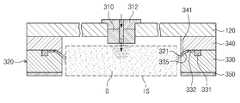
도 2는 도 1의 가스 공급부를 나타내는 단면도이고, 도 3은 도 2의 가스 공급부를 나타내는 분해 사시도이다. 도 1 내지 도 3을 참조하면, 가스 공급부(300)는 제1노즐(310), 제2노즐(320), 가스 공급 라인(360), 그리고 가스 저장부(370)를 포함한다. 제1노즐(100)은 밀폐 커버(120)의 중앙부에 위치한다. 제1노즐(310)에는 분사홀(311)이 형성된다. 분사홀(311)은 여기 공간(IS)의 중심영역으로 공정 가스를 공급한다. 제1노즐(310)은 노즐 지지 로드(312)에 의해 지지되어 밀폐 커버(120)에 위치될 수 있다.Fig. 2 is a cross-sectional view showing the gas supply unit in Fig. 1, and Fig. 3 is an exploded perspective view showing the gas supply unit in Fig. Referring to FIGS. 1 to 3, the
제2노즐(320)은 여기 공간(IS)을 에워싸는 링 형상으로 제공된다. 제2노즐(320)의 내측면에는 공급 유로(321)가 형성된다. 공급 유로(321)는 제2노즐(320)의 내측면을 따라 연속적으로 제공될 수 있다. 공급 유로(321)는 여기 공간(IS)의 가장자리영역으로 공정 가스를 공급한다. 제2노즐(320)은 가스 링(330), 상부 커버 링(340), 그리고 하부 커버 링(350)을 포함한다.The
가스 링(330)은 링 형상으로 제공되며, 여기 공간(IS)의 둘레를 따라 제공된다. 가스 링(330)의 상면에는 가스 순환 홈(331), 가스 공급 홈(332)이 형성된다. 가스 순환 홈(331)은 링 형상의 홈으로, 가스 링(310)의 둘레를 따라 제공된다. 가스 순환 홈(331)은 공정 가스가 순환하는 통로를 제공한다. 가스 순환 홈(331)을 따라 순환하는 공정 가스는 가스 공급 홈(332)들 각각으로 공급된다. 가스 공급 홈(332)들은 가스 순환 홈(331)과 공급 유로(321)를 연결하며, 가스 순환 홈(331)을 따라 순환하는 공정 가스가 공급 유로(321)로 제공되는 통로를 제공한다. 가스 공급 홈(332)들은 여기 공간(IS)과 인접한 가스 링(330)의 내측부와 가스 순환 홈(331)의 사이 영역에 형성된다. 가스 공급 홈(332)들은 가스 링(330)의 둘레를 따라 서로 이격하여 복수개 형성된다. 가스 공급 홈(332)은 도 4와 같이, 깊이(H)에 비하여 너비(W)가 크게 제공되는 슬릿 홈으로 제공된다. 가스 공급 홈(332)은 직사각의 얇은 슬릿 형상으로 제공될 수 있다. 가스 공급 홈(332)의 깊이(H)는 되도록 얕게 제공하는 것이 바람직하다. 가스 공급 홈(332)의 깊이(H)가 깊어질 경우, 공정 가스가 가스 공급 홈(332)을 통과하는 과정에서 플라스마 상태로 여기될 수 있다. 또한, 공정 가스가 여기되는 과정에서 아크 방전이 발생되어 가스 링(330) 및 상부 커버 링(340)이 손상될 수 있다. 가스 공급 홈(332)의 깊이(H)가 얕아질 경우, 상술한 문제 발생이 최소화될 수 있다. 가스 공급 홈(332)을 통해 공급되는 공정 가스의 유량은 가스 공급 홈(332)의 너비(W)를 크게 함으로써 조절가능하다. 가스 링(330)의 내측부 상면은 경사면(335)으로 제공된다. 경사면(335)은 여기 공간(IS)에 인접할수록 그 높이가 점점 낮아지도록 하향 경사진다. 경사면(335)의 하단은 그 높이가 가스 공급 홈(332)의 바닥면 높이보다 낮게 위치한다.The
상부 커버 링(340)은 가스 링(330)에 상응하는 반경을 가지는 링 형상으로 제공되며, 가스 링(330)의 상면에 놓인다. 상부 커버 링(340)의 저면은 가스 순환 홈(331)의 개방된 상면과 가스 공급 홈(332)의 개방된 상면을 밀폐시킨다. 가스 순환 홈(331)과 상부 커버 링(340)의 저면은 조합되어 공정 가스가 순환하는 통로를 형성하며, 가스 공급 홈(332)과 상부 커버 링(340)의 저면은 조합되어 공정 가스가 가스 순환 홈(331)으로부터 공급 유로(321)로 공급되는 통로를 제공한다. 여기 공간(IS)에 인접한 상부 커버 링(340)의 내측부는 그 저면이 경사면(341)으로 제공된다. 상부 커버 링의(340) 경사면(341)은 여기 공간(IS)에 인접할수록 그 높이가 점점 낮아지도록 하향 경사진다. 상부 커버 링(340)의 경사면(341)은 가스 링(330)의 경사면(335)과 동일한 각도로 경사진다. 상부 커버 링(340)의 경사면(341)은 가스 링(330)의 경사면(335)과 소정 간격으로 이격되며, 서로 나란하게 배치된다. 상부 커버 링(340)의 경사면(341) 하단은 그 높이가 가스 공급 홈(332)들의 바닥면 높이보다 낮게 위치한다. 이에 의해, 가스 공급 홈(332)들은 상부 커버링(340)에 가려 여기 공간(IS) 내에 노출되지 않는다. 가스 공급 홈(332)들이 여기 공간(IS)에 노출될 경우, 여기 공간(IS)에서 발생하는 플라스마는 가스 공급 홈(332)들을 식각한다. 가스 공급 홈(332)들의 식각은 가스 공급 홈(332)들의 크기를 변경하여 홈(332)을 통해 공급되는 공정 가스의 유량을 변화시킨다. 또한, 식각 과정에서 발생된 부산물은 기판(W)으로 공급되어 기판 오염원으로 작용한다. 상부 커버링(340)의 경사면(341)은 가스 공급 홈(332)들이 여기 공간(IS) 내에 직접 노출되는 것을 차단하여 상술한 가스 공급 홈(332)들의 식각을 예방한다. 상부 커버 링(340)의 경사면(341)과 가스 링(330)의 경사면(335)은 서로 조합되어 공급 유로(321)를 형성한다. 가스 공급 홈(332)들을 통해 공급된 공정 가스는 공급 유로(321)를 따라 하향 경사지게 여기 공간(IS)의 가장자리영역으로 공급된다.The
하부 커버 링(350)은 가스 링(330)의 하부에 위치한다. 하부 커버 링(350)은 가스 링(330)에 상응하는 반경을 가지는 링 형상으로 제공될 수 있다. 하부 커버 링(350)은 절연 재질로 제공될 수 있다.The
가스 공급 라인(360)은 분기되어 제1노즐(310)과 제2노즐(320)에 각각 연결된다. 가스 공급 라인(360)은 가스 저장부(370)에 저장된 공정 가스를 제1노즐(310)의 분사홀(311)과 제2노즐(320)의 가스 순환 홈(321)으로 각각 공급한다.The
플라스마 생성부(400)는 공정 챔버(100) 내부에 고주파 전력을 인가하여 공정 챔버(100) 내부에 공급된 공정 가스를 여기시킨다. 플라스마 생성부(400)는 하우징(410), 상부 전원(420), 그리고 안테나(430)를 포함한다.The
하우징(410)은 저면이 개방되며, 내부에 공간이 형성된다. 하우징(410)은 밀폐 커버(120)의 상부에 위치하며, 밀폐 커버(120)의 상면에 놓인다. 하우징(410)의 내부는 안테나(430)가 위치하는 공간으로 제공된다. 상부 전원(420)은 고주파 전류를 발생시킨다. 발생된 고주파 전류는 안테나(430)에 인가된다. 안테나(430)는 공정 챔버(100) 내부에 고주파 전력을 인가한다. 안테나(430)는 서로 상이한 반경을 갖는 링 형상의 코일들이 동일한 중심에 위치되도록 배치될 수 있다.
The
도 5와 같이, 제1노즐(310)과 제2노즐(320)은 여기 공간(IS)의 상이한 영역으로 공정 가스(G)를 공급하므로, 여기 공간(IS) 내에는 공정 가스(G)가 균일하게 제공될 수 있다. 이는 여기 공간(IS) 내의 플라스마 밀도 분포를 균일하게 하여 기판 전체면이 균일하게 처리될 수 있다. 또한, 가스 공급 홈(332)들이 슬릿 홈으로 형성되고, 상부 커버 링(340)의 경사면(341)에 의해 가스 공급 홈(332)들이 여기 공간에 직접 노출되지 않으므로, 가스 링(330) 및 상부 커버 링(340)의 손상이 최소화될 수 있다. 또한, 장시간 사용으로 가스 링(330)과 상부 커버 링(340)에 손상이 발생하더라도, 가스 링(330)과 상부 커버 링(340)을 분리하여 그 표면을 재코팅할 수 있으므로 유지 보수가 용이하다.
5, since the
상기 실시예에서는 기판 지지부(200)가 정전 척인 것으로 설명하였으나, 이와 달리 기판 지지부는 다양한 방법으로 기판을 지지할 수 있다. 예컨대, 기판 지지부(200)는 기판을 진공으로 흡착 유지하는 진공 척으로 제공될 수 있다.Although the
또한, 상기 실시예에서는 플라스마를 이용하여 식각 공정을 수행하는 것으로 설명하였으나, 기판 처리 공정은 이에 한정되지 않으며, 플라스마를 이용하는 다양한 기판 처리 공정, 예컨대 증착 공정, 애싱 공정, 그리고 세정 공정등에도 적용될수 있다.
In the above embodiment, the etching process is performed using plasma. However, the substrate process is not limited thereto, and can be applied to various substrate processing processes using plasma, such as a deposition process, an ashing process, and a cleaning process have.
이상의 설명은 본 발명의 기술 사상을 예시적으로 설명한 것에 불과한 것으로서, 본 발명이 속하는 기술 분야에서 통상의 지식을 가진 자라면 본 발명의 본질적인 특성에서 벗어나지 않는 범위에서 다양한 수정 및 변형이 가능할 것이다. 따라서, 본 발명에 개시된 실시 예들은 본 발명의 기술 사상을 한정하기 위한 것이 아니라 설명하기 위한 것이고, 이러한 실시 예에 의하여 본 발명의 기술 사상의 범위가 한정되는 것은 아니다. 본 발명의 보호 범위는 아래의 청구범위에 의하여 해석되어야 하며, 그와 동등한 범위 내에 있는 모든 기술 사상은 본 발명의 권리범위에 포함되는 것으로 해석되어야 할 것이다.The foregoing description is merely illustrative of the technical idea of the present invention, and various changes and modifications may be made by those skilled in the art without departing from the essential characteristics of the present invention. Therefore, the embodiments disclosed in the present invention are intended to illustrate rather than limit the scope of the present invention, and the scope of the technical idea of the present invention is not limited by these embodiments. The scope of protection of the present invention should be construed according to the following claims, and all technical ideas within the scope of equivalents should be construed as falling within the scope of the present invention.
100: 공정 챔버200: 기판 지지부
300: 가스 공급부310: 제1노즐
320: 제2노즐330: 가스 링
340: 상부 커버 링350: 하부 커버 링100: process chamber 200: substrate support
300: gas supply unit 310: first nozzle
320: second nozzle 330: gas ring
340: upper cover ring 350: lower cover ring
Claims (6)
Translated fromKorean상기 공정 챔버 내부에 위치하며, 기판을 지지하는 기판 지지부;
상기 기판 지지부의 상부에 위치된 여기 공간으로 공정 가스를 공급하는 가스공급부; 및
상기 여기 공간으로 고주파 전력을 인가하여 공정 가스를 여기시키는 안테나를 포함하되,
상기 가스 공급부는
상기 여기 공간의 중심영역 상부에 위치하며, 상기 여기공간의 중심영역으로 공정가스를 공급하는 제1노즐; 및
상기 여기 공간을 에워싸는 링 형상으로 제공되며, 상기 여기 공간의 가장자리영역으로 공정가스를 공급하는 공급 유로가 내측면에 형성된 제2노즐을 포함하며,
상기 제2노즐은,
상기 공정 챔버를 둘러싸는 가스 링과,
상기 가스 링의 상면에 놓이는 커버 링을 포함하되,
상기 가스 링과 상기 커버 링의 사이에는 공정가스가 순환하는 가스순환 홈이 상기 가스 링의 둘레를 따라 형성되고, 상기 가스순환 홈과 상기 공급 유로를 연결하는 가스공급 홈이 상기 가스 링의 둘레를 따라 이격하여 복수 개 형성되고,
상기 공급 유로는 상기 가스 링의 상면과 상기 커버 링의 하면 사이에 원주 방향으로 형성되는 슬릿 형상으로 마련되는 기판 처리 장치.A process chamber in which a space is formed;
A substrate support positioned within the process chamber and supporting the substrate;
A gas supply for supplying a process gas to an excitation space located above the substrate support; And
And an antenna for exciting the process gas by applying a high frequency power to the excitation space,
The gas supply part
A first nozzle positioned above a central region of the excitation space and supplying a process gas to a central region of the excitation space; And
And a second nozzle provided on an inner surface of the inner circumferential surface of the excitation space and provided with a supply passage for supplying a process gas to an edge region of the excitation space,
The second nozzle
A gas ring surrounding the process chamber,
A cover ring disposed on an upper surface of the gas ring,
A gas circulation groove in which a process gas is circulated is formed along the circumference of the gas ring, and a gas supply groove connecting the gas circulation groove and the supply passage is formed around the gas ring A plurality of spaced-
Wherein the supply passage is provided in a slit shape formed in a circumferential direction between an upper surface of the gas ring and a lower surface of the cover ring.
상기 공급 유로는 상기 제2노즐의 내측면을 따라 연속적으로 제공되는 기판 처리 장치.The method according to claim 1,
Wherein the supply passage is provided continuously along an inner surface of the second nozzle.
상기 가스순환 홈과 상기 가스공급 홈은 상기 가스 링의 상면에 형성되는 기판 처리 장치.3. The method according to claim 1 or 2,
Wherein the gas circulation groove and the gas supply groove are formed on the upper surface of the gas ring.
상기 가스 공급 홈은 너비가 깊이보다 큰 슬릿 홈인 기판 처리 장치.The method of claim 3,
Wherein the gas supply groove is a slit groove having a width larger than the depth.
상기 여기 공간에 인접한 상기 가스 링의 내측부 상면은 상기 여기 공간에 인접될수록 그 높이가 점점 낮아지도록 하향 경사진 경사면으로 제공되며,
상기 커버링의 내측부 상면은 상기 가스 링의 경사면과 소정 간격 이격되어 나란하게 경사진 경사면으로 제공되며,
상기 공급 유로는 상기 가스 링의 경사면과 상기 커버 링의 경사면이 조합되어 형성되는 기판 처리 장치.The method according to claim 1,
Wherein the upper surface of the inner side portion of the gas ring adjacent to the excitation space is provided with a downwardly inclined slope so that the height thereof becomes gradually lower toward the excitation space,
Wherein the upper surface of the inner side of the covering is provided with an inclined surface which is inclined in parallel to the inclined surface of the gas ring by a predetermined distance,
Wherein the supply passage is formed by combining an inclined surface of the gas ring and an inclined surface of the cover ring.
상기 커버링의 내측부 하단은 그 높이가 상기 가스 공급 홈의 높이보다 낮게 위치되는 기판 처리 장치.6. The method of claim 5,
And the lower end of the inner bottom of the covering is positioned lower than the height of the gas supply groove.
Priority Applications (1)
| Application Number | Priority Date | Filing Date | Title |
|---|---|---|---|
| KR1020110090375AKR101885108B1 (en) | 2011-09-06 | 2011-09-06 | Apparatus for treatimg substrate |
Applications Claiming Priority (1)
| Application Number | Priority Date | Filing Date | Title |
|---|---|---|---|
| KR1020110090375AKR101885108B1 (en) | 2011-09-06 | 2011-09-06 | Apparatus for treatimg substrate |
Publications (2)
| Publication Number | Publication Date |
|---|---|
| KR20130026917A KR20130026917A (en) | 2013-03-14 |
| KR101885108B1true KR101885108B1 (en) | 2018-08-07 |
Family
ID=48178044
Family Applications (1)
| Application Number | Title | Priority Date | Filing Date |
|---|---|---|---|
| KR1020110090375AActiveKR101885108B1 (en) | 2011-09-06 | 2011-09-06 | Apparatus for treatimg substrate |
Country Status (1)
| Country | Link |
|---|---|
| KR (1) | KR101885108B1 (en) |
Citations (4)
| Publication number | Priority date | Publication date | Assignee | Title |
|---|---|---|---|---|
| JP2003332315A (en)* | 2002-05-15 | 2003-11-21 | Matsushita Electric Ind Co Ltd | Plasma processing apparatus and method |
| US20070281106A1 (en) | 2006-05-30 | 2007-12-06 | Applied Materials, Inc. | Process chamber for dielectric gapfill |
| US20080264784A1 (en) | 2004-06-18 | 2008-10-30 | Peter Pecher | Media Injector |
| JP2010183092A (en)* | 2005-11-15 | 2010-08-19 | Panasonic Corp | Plasma treatment apparatus |
- 2011
- 2011-09-06KRKR1020110090375Apatent/KR101885108B1/enactiveActive
Patent Citations (4)
| Publication number | Priority date | Publication date | Assignee | Title |
|---|---|---|---|---|
| JP2003332315A (en)* | 2002-05-15 | 2003-11-21 | Matsushita Electric Ind Co Ltd | Plasma processing apparatus and method |
| US20080264784A1 (en) | 2004-06-18 | 2008-10-30 | Peter Pecher | Media Injector |
| JP2010183092A (en)* | 2005-11-15 | 2010-08-19 | Panasonic Corp | Plasma treatment apparatus |
| US20070281106A1 (en) | 2006-05-30 | 2007-12-06 | Applied Materials, Inc. | Process chamber for dielectric gapfill |
Also Published As
| Publication number | Publication date |
|---|---|
| KR20130026917A (en) | 2013-03-14 |
Similar Documents
| Publication | Publication Date | Title |
|---|---|---|
| US10103018B2 (en) | Apparatus for treating substrate | |
| JP7098273B2 (en) | Universal process kit | |
| KR101951369B1 (en) | Electrostatic chuck and substrate treating apparatus including the chuck | |
| US10777387B2 (en) | Apparatus for treating substrate | |
| US20140116622A1 (en) | Electrostatic chuck and substrate processing apparatus | |
| JP2019522889A (en) | High power electrostatic chuck design with high frequency coupling | |
| KR101670457B1 (en) | Support unit and apparatus for treating substrate with the support unit | |
| US20130220975A1 (en) | Hybrid plasma processing systems | |
| KR102330281B1 (en) | Electrostatic chuck and substrate treating apparatus including the chuck | |
| KR102323320B1 (en) | Apparatus and method for treating substrate comprising the same | |
| KR102050820B1 (en) | Substrate supporting unit and substrate treating apparatus including the unit | |
| KR101395229B1 (en) | Apparatus for treating substrate | |
| KR101885102B1 (en) | Ntenna unit and substrate treating apparatus including the unit | |
| KR20130026916A (en) | Apparatus for treating substrate | |
| KR101909473B1 (en) | Apparatus for treating substrate | |
| KR101430745B1 (en) | Electrostatic chuck and substrate treating apparatus | |
| KR20210027648A (en) | Apparatus for treating substrate and method for cleaning chamber | |
| KR101885108B1 (en) | Apparatus for treatimg substrate | |
| KR101966797B1 (en) | Apparatus for treating substrate | |
| KR102344523B1 (en) | Supporting unit and substrate treating apparatus including the chuck | |
| KR20240016705A (en) | Substrate support apparatus and substrate processing apparatus including same | |
| KR101408790B1 (en) | Apparatus for treating substrate | |
| KR102262107B1 (en) | Substrate treating apparatus | |
| KR101909472B1 (en) | Apparatus for treating substrate | |
| KR101935959B1 (en) | Microwave antenna and substrate treating apparatus including the antenna |
Legal Events
| Date | Code | Title | Description |
|---|---|---|---|
| PA0109 | Patent application | Patent event code:PA01091R01D Comment text:Patent Application Patent event date:20110906 | |
| PG1501 | Laying open of application | ||
| A201 | Request for examination | ||
| PA0201 | Request for examination | Patent event code:PA02012R01D Patent event date:20160902 Comment text:Request for Examination of Application Patent event code:PA02011R01I Patent event date:20110906 Comment text:Patent Application | |
| E902 | Notification of reason for refusal | ||
| PE0902 | Notice of grounds for rejection | Comment text:Notification of reason for refusal Patent event date:20170929 Patent event code:PE09021S01D | |
| E701 | Decision to grant or registration of patent right | ||
| PE0701 | Decision of registration | Patent event code:PE07011S01D Comment text:Decision to Grant Registration Patent event date:20180723 | |
| GRNT | Written decision to grant | ||
| PR0701 | Registration of establishment | Comment text:Registration of Establishment Patent event date:20180730 Patent event code:PR07011E01D | |
| PR1002 | Payment of registration fee | Payment date:20180731 End annual number:3 Start annual number:1 | |
| PG1601 | Publication of registration | ||
| PR1001 | Payment of annual fee | Payment date:20210701 Start annual number:4 End annual number:4 | |
| PR1001 | Payment of annual fee | Payment date:20240625 Start annual number:7 End annual number:7 | |
| PR1001 | Payment of annual fee | Payment date:20250625 Start annual number:8 End annual number:8 |