KR101885105B1 - Apparatus and method for treating substrate - Google Patents
Apparatus and method for treating substrateDownload PDFInfo
- Publication number
- KR101885105B1 KR101885105B1KR1020110088500AKR20110088500AKR101885105B1KR 101885105 B1KR101885105 B1KR 101885105B1KR 1020110088500 AKR1020110088500 AKR 1020110088500AKR 20110088500 AKR20110088500 AKR 20110088500AKR 101885105 B1KR101885105 B1KR 101885105B1
- Authority
- KR
- South Korea
- Prior art keywords
- liner
- substrate
- rotating
- process gas
- opening
- Prior art date
- Legal status (The legal status is an assumption and is not a legal conclusion. Google has not performed a legal analysis and makes no representation as to the accuracy of the status listed.)
- Active
Links
Images


Classifications
- H—ELECTRICITY
- H01—ELECTRIC ELEMENTS
- H01J—ELECTRIC DISCHARGE TUBES OR DISCHARGE LAMPS
- H01J37/00—Discharge tubes with provision for introducing objects or material to be exposed to the discharge, e.g. for the purpose of examination or processing thereof
- H01J37/32—Gas-filled discharge tubes
- H01J37/32431—Constructional details of the reactor
- H01J37/32458—Vessel
- H01J37/32477—Vessel characterised by the means for protecting vessels or internal parts, e.g. coatings
- H01J37/32495—Means for protecting the vessel against plasma
Landscapes
- Physics & Mathematics (AREA)
- Engineering & Computer Science (AREA)
- Plasma & Fusion (AREA)
- Chemical & Material Sciences (AREA)
- Analytical Chemistry (AREA)
- Drying Of Semiconductors (AREA)
- Plasma Technology (AREA)
Abstract
Translated fromKoreanDescription
Translated fromKorean본 발명은 기판 처리 장치 및 방법에 관한 것으로, 보다 상세하게는 플라스마를 이용하여 기판을 처리하는 장치 및 방법에 관한 것이다.The present invention relates to a substrate processing apparatus and method, and more particularly, to an apparatus and a method for processing a substrate using plasma.
플라스마는 매우 높은 온도나, 강한 전계 혹은 고주파 전자계(RF Electromagnetic Fields)에 의해 생성되며, 이온이나 전자, 라디칼등으로 이루어진 이온화된 가스 상태를 말한다. 반도체 소자 제조 공정은 플라스마를 사용하여 식각 공정을 수행한다. 식각 공정은 플라스마에 함유된 이온 입자들이 기판과 충돌함으로써 수행된다.Plasma is an ionized gas state produced by very high temperature, strong electric field or RF electromagnetic fields, and composed of ions, electrons, radicals, and so on. The semiconductor device fabrication process employs a plasma to perform the etching process. The etching process is performed by colliding the ion particles contained in the plasma with the substrate.
공정 처리가 수행되는 공정 챔버의 내부에는 공정 챔버의 내측면을 보호하기 위한 라이너가 제공된다. 공정 챔버와 라이너 각각에는 기판이 출입하는 개구가 형성된다. 공정 가스는 공정 챔버의 개구와 라이너의 개구로 확산되므로, 공정 챔버 내부에서 공정 가스의 밀도 분포가 불균일해진다. 이러한 공정 가스의 확산을 방지하기 위하여, 공정 챔버의 내부에는 라이너의 개구를 개폐하는 셔터가 제공되나, 셔터는 공정 챔버 내부에서 별도의 공간을 차지하고, 접지에 취약하여 공정 가스가 여기되는 과정에서 아크 방전을 일으키는 요인이 될 수 있다.Inside the process chamber in which process processing is performed is provided a liner for protecting the inner surface of the process chamber. In each of the process chamber and the liner, an opening through which the substrate enters and leaves is formed. The process gas is diffused into the openings of the process chamber and the liner so that the density distribution of the process gas inside the process chamber becomes non-uniform. In order to prevent the diffusion of the process gas, a shutter for opening and closing an opening of the liner is provided in the process chamber. However, the shutter occupies a separate space inside the process chamber, Which may cause a discharge.
본 발명의 실시예들은 기판을 균일하게 처리할 수 있는 장치 및 방법을 제공한다.Embodiments of the present invention provide an apparatus and method for uniformly treating a substrate.
본 발명의 일 실시예에 따른 기판 처리 장치는 기판을 처리하기 위한 공간이 내부에 형성된 몸체; 상기 몸체 내에 위치하며, 상기 기판을 지지하는 기판 지지부; 상기 몸체 내부에 공정 가스를 공급하는 가스 공급부; 상기 몸체 내부에 고주파 전력을 인가하여 상기 몸체 내부에 머무르는 공정 가스를 여기시키는 안테나; 상기 몸체의 내측면을 따라 제공되며, 상기 공정 가스가 여기되는 여기 공간을 에워싸는 라이너; 및 상기 라이너를 회전시키는 라이너 회전부를 포함한다.A substrate processing apparatus according to an embodiment of the present invention includes: a body having a space therein for processing a substrate; A substrate support positioned within the body and supporting the substrate; A gas supply unit for supplying a process gas into the body; An antenna for applying a high frequency power to the inside of the body to excite a process gas staying inside the body; A liner provided along the inner side of the body and surrounding the excitation space into which the process gas is excited; And a liner rotating unit for rotating the liner.
또한, 상기 몸체의 측벽에는 상기 기판이 출입하는 개구가 형성되고, 상기 라이너의 측벽에는 상기 기판이 출입하는 통로가 형성되고, 상기 라이너 회전부는 상기 통로가 상기 개구와 일직선상에 위치하는 제1위치와 상기 통로가 상기 개구와 서로 상이한 직선상에 위치하는 제2위치간에 상기 라이너를 회전시킬 수 있다.In addition, a sidewall of the body is provided with an opening through which the substrate enters and exits, a sidewall of the liner is provided with a passage through which the substrate enters and exits, and the liner rotation portion includes a first position where the passage is aligned with the opening And a second position in which the passage is located on a straight line that is different from the opening.
또한, 상기 제2위치에서 상기 통로와 일직선상에 위치하고, 상기 몸체의 내측면에 탈착가능하게 설치되며, 상기 라이너와 동일한 재질로 제공되는 보조 라이너를 더 포함할 수 있다.The apparatus may further include a secondary liner disposed on the inner surface of the body in a straight line with the passage at the second position and provided with the same material as the liner.
또한, 상기 라이너 회전부는 상기 몸체의 내부에 위치하며, 상기 라이너의 하단에 고정 결합하는 회전 링; 상기 회전 링의 외주면을 따라 상이한 극성의 자석들이 교대로 반복적으로 배치되는 제1자석부; 상기 몸체의 외부에서 상기 회전 링과 동일 높이에 위치하는 회전 몸체; 상기 회전 몸체의 외주면을 따라 상이한 극성의 자석들이 교대로 반복적으로 배치되는 제2자석부; 및 상기 회전 몸체를 회전시키는 구동부를 포함할 수 있다.In addition, the liner rotating part is located inside the body and is fixed to the lower end of the liner; A first magnet portion in which magnets of different polarities are alternately and repeatedly arranged along an outer peripheral surface of the rotary ring; A rotating body located outside the body at the same height as the rotating ring; A second magnet portion in which magnets of different polarities are alternately and repeatedly arranged along an outer peripheral surface of the rotating body; And a driving unit for rotating the rotating body.
또한, 상기 라이너 회전부는 상기 몸체와 상기 라이너 사이에 설치되며, 상기 라이너의 회전을 보조하는 베어링을 더 포함할 수 있다.The liner rotating unit may further include a bearing installed between the body and the liner to assist rotation of the liner.
본 발명의 일 실시예에 따른 기판 처리 방법은 몸체의 개구와 라이너의 통로를 일직선상에 위치시키고, 상기 개구와 상기 통로를 통하여 상기 몸체의 내부로 기판을 제공하고, 상기 개구와 상기 통로가 서로 상이한 직선상에 위치하도록 상기 라이너를 회전시켜 상기 개구를 차단하며, 상기 몸체 내부에 공급된 공정 가스를 여기시켜 상기 기판을 처리한다.A substrate processing method in accordance with an embodiment of the present invention includes positioning a passage of a body and a liner in a straight line, providing a substrate into the interior of the body through the opening and the passage, The liner is rotated to position the substrate on a different straight line to block the opening, and the substrate is processed by exciting the process gas supplied to the inside of the body.
또한, 상기 라이너는 비접촉방식에 의해 회전될 수 있다.Further, the liner can be rotated by a non-contact method.
또한, 상기 라이너에 연결된 회전 링의 외주면을 따라 서로 상이한 극성의 제1자석들이 교대로 반복적으로 배치되고, 상기 몸체의 외부에 위치된 회전 몸체의 외주면을 따라 서로 상이한 극성의 제2자석들이 교대로 반복적으로 배치되며, 상기 라이너는 상기 회전 몸체의 회전으로 발생된 상기 제1자석들과 상기 제2자석들의 자력 변화에 의해 회전될 수 있다.Further, first magnets of mutually different polarities are alternately and repeatedly arranged along the outer circumferential surface of the rotary ring connected to the liner, and second magnets of different polarities are alternately arranged along the outer circumferential surface of the rotating body located outside the body And the liner can be rotated by a magnetic force change of the first magnets and the second magnets generated by the rotation of the rotating body.
본 발명의 실시예들에 의하면, 플라스마 밀도 분포가 균일하게 발생되므로 기판 처리가 균일하게 이루어질 수 있다.According to the embodiments of the present invention, since the plasma density distribution is uniformly generated, the substrate processing can be performed uniformly.
도 1은 본 발명의 일 실시예에 따른 기판 처리 장치를 나타내는 단면도이다.
도 2 및 도 3은 도 1의 몸체와 리니어가 배치되는 모습을 나타내는 단면도이다.
도 4는 도 1의 라이너 회전부를 나타내는 사시도이다.
도 5는 도 4의 회전 링과 회전 몸체의 단면을 나타내는 도면이다.1 is a cross-sectional view showing a substrate processing apparatus according to an embodiment of the present invention.
Figs. 2 and 3 are cross-sectional views showing a state in which the body and the linear in Fig. 1 are arranged. Fig.
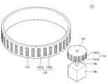
Fig. 4 is a perspective view showing the liner rotating unit of Fig. 1;
Fig. 5 is a view showing a section of the rotating ring and the rotating body of Fig. 4;
이하 첨부된 도면을 참조하여 본 발명의 바람직한 실시 예에 따른 기판 처리 장치 및 방법을 상세히 설명한다. 본 발명을 설명함에 있어, 관련된 공지 구성 또는 기능에 대한 구체적인 설명이 본 발명의 요지를 흐릴 수 있다고 판단되는 경우에는 그 상세한 설명은 생략한다.
DETAILED DESCRIPTION OF THE PREFERRED EMBODIMENT Hereinafter, an apparatus and a method for processing a substrate according to a preferred embodiment of the present invention will be described in detail with reference to the accompanying drawings. In the following description of the present invention, a detailed description of known functions and configurations incorporated herein will be omitted when it may make the subject matter of the present invention rather unclear.
도 1은 본 발명의 일 실시예에 따른 기판 처리 장치를 나타내는 단면도이다.1 is a cross-sectional view showing a substrate processing apparatus according to an embodiment of the present invention.
도 1을 참조하면, 기판 처리 장치(10)는 플라스마를 이용하여 기판(W)을 처리한다. 기판 처리 장치(10)는 공정 챔버(100), 기판 지지부(200), 가스 공급부(300), 그리고, 플라스마 생성부(400)를 포함한다.Referring to FIG. 1, a
공정 챔버(100)는 기판(W) 처리 공정이 수행되는 공간을 제공한다. 공정 챔버(100)는 몸체(110), 밀폐 커버(120), 라이너(130), 라이너 회전부(140), 보조 라이너(170)를 포함한다.The
몸체(110)에는 상면이 개방된 공간이 내부에 형성된다. 몸체(110)의 내부 공간은 기판(W) 처리 공정이 수행되는 공간으로 제공된다. 몸체(110)는 금속 재질로 제공된다. 몸체(100)는 알루미늄 재질로 제공될 수 있다. 몸체(110)의 측벽에는 개구(111)가 형성된다. 개구(111)는 기판이 몸체(110) 내부로 이송되는 통로를 제공한다. 몸체(110)의 바닥면에는 배기홀(102)이 형성된다. 배기홀(102)은 배기 라인(181)과 연결된다. 공정 과정에서 발생한 반응 부산물 및 몸체의 내부 공간에 머무르는 가스는 배기 라인(181)을 통해 외부로 배출될 수 있다. 배기 과정에 의해 몸체(110) 내부는 소정 압력으로 감압된다.In the
밀폐 커버(120)는 몸체(110)의 개방된 상면을 덮는다. 밀폐 커버(120)는 판 형상으로 제공되며, 몸체(110)의 내부공간을 밀폐시킨다. 밀폐 커버(120)는 몸체(110)와 상이한 재질로 제공될 수 있다. 밀폐 커버(120)는 유전체(dielectric substance)로 제공될 수 있다.The
라이너(130)는 몸체(110) 내부에 제공된다. 라이너(130)는 상면 및 하면이 개방된 공간이 내부에 형성된다. 라이너(130)는 원통 형상으로 제공될 수 있다. 라이너(130)는 몸체(110)의 내측면에 상응하거나 그보다 작은 반경을 가질 수 있다. 라이너(130)는 몸체(110)의 내측면을 따라 제공된다. 라이너(130)의 상단에는 지지 링(131)이 형성된다. 지지 링(131)은 링 형상의 판으로 제공되며, 라이너(130)의 둘레를 따라 라이너(130)의 외측으로 돌출된다. 지지 링(131)은 몸체(110)의 상단에 놓이며, 라이너(130)를 지지한다. 라이너(130)의 측벽에는 통로(132)가 형성된다. 통로(132)를 통하여 기판(W)이 라이너(130) 내부로 제공된다. 라이너(130)는 몸체(110)와 동일한 재질로 제공될 수 있다. 라이너(130)는 알루미늄 재질로 제공될 수 있다. 라이너(130)는 몸체(110) 내측면을 보호한다. 공정 가스가 여기되는 과정에서 공정 챔버(100) 내부에는 아크(Arc) 방전이 발생될 수 있다. 아크 방전은 주변 장치들을 손상시킨다. 라이너(130)는 몸체(110)의 내측면을 보호하여 몸체(110)의 내측면이 아크 방전으로 손상되는 것을 방지한다. 라이너(130)는 몸체(110)에 비하여 비용이 저렴하고, 교체가 용이하다. 따라서, 아크 방전으로 라이너(130)이 손상될 경우, 새로운 라이너로 교체할 수 있다.The
라이너 회전부(140)는 라이너(130)를 회전시킨다. 라이너 회전부(140)는 비접촉방식에 의해 라이너(130)를 회전시킬 수 있다. 라이너 회전부(140)는 몸체(110)의 개구(111)와 라이너(130)의 통로(132)가 제1위치 또는 제2위치에 위치하도록 라이너(130)를 회전시킨다. 제1위치에서는 도 2와 같이, 몸체(110)의 개구(111)와 라이너(130)의 통로(132)가 일직선상에 위치하고, 제2위치에서는 도 3과 같이, 몸체(110)의 개구(111)와 라이너(130)의 통로(132)가 서로 상이한 직선상에 위치한다. 몸체(110)의 개구(111)와 라이너(130)의 통로(132)가 제1위치에 위치하는 상태에서 기판(W)이 몸체(110) 내부로 이송된다. 그리고, 몸체(110)의 개구(111)와 라이너(130)의 통로(132)가 제2위치에 위치하는 상태에서 기판(W)에 대한 공정 처리가 수행된다.The
도 4는 라이너 회전부를 나타내는 사시도이다.4 is a perspective view showing the liner rotating part.
도 1 및 도 4를 참조하면, 라이너 회전부(140)는 회전 링(141), 제1자석부(142), 회전 몸체(143), 제2자석부(144), 회전 로드(145), 구동기(146), 그리고 베어링(147)을 포함한다.1 and 4, the
회전 링(141)은 몸체(110)의 내부에 위치하며, 라이너(130)와 동일한 반경을 가지는 링 형상으로 제공된다. 회전 링(141)은 라이너(130)의 하부에 위치하며, 라이너(130)의 하단에 고정 결합된다.The
제1자석부(142)는 제2자석부(144)와 자력에 의해 라이너(130)를 회전시킨다. 제1자석부(142)는 회전 링(141)의 외주면을 따라 배치되는 복수개의 제1자석(142a, 142b)들을 포함한다. 제1자석(142a, 142b)들은 서로 상이한 극성이 교대로, 그리고 반복적으로 배치된다. 인접한 제1자석(142a, 142b)들은 서로 상이한 극성을 갖는다.The
회전 몸체(143)는 몸체(110)의 외부에 위치한다. 회전 몸체(143)는 회전 링(141)과 동일한 높이에 위치한다. 회전 몸체(143)는 원통 형상으로 제공된다. 회전 몸체(143)에는 제2자석부(144)가 제공된다. 제2자석부(144)는 회전 몸체(143)의 회전력을 제1자석부(142)에 전달한다. 제2자석부(144)는 회전 몸체(143)의 외주면을 따라 배치되는 복수개의 제2자석(144a, 144b)들을 포함한다. 제2자석(144a, 144b)들은 서로 상이한 극성이 교대로, 그리고 반복적으로 배치된다. 인접한 제2자석(144a, 144b)들은 서로 상이한 극성을 갖는다. 제2자석(144a, 144b)들은 제1자석(142a, 144b)들과 마주하여 배치된다.The
회전 로드(145)는 회전 몸체(143)의 하부에 수직방향으로 제공되며, 회전 몸체(143)의 중심에 삽입 고정된다. 구동기(146)는 회전 로드(145)의 하단에 결합되며, 회전 로드(145)의 길이방향과 나란한 축을 중심으로 회전 로드(145)를 회전시킨다.The
베어링(147)은 라이너(130)의 회전을 보조한다. 베어링(147)은 라이너(130)와 몸체(110) 사이에 제공된다. 베어링(147)의 내륜은 라이너(130)의 외주면을 따라 제공되며, 라이너(130)에 고정 설치된다. 베어링(147)의 외륜은 몸체(110)의 내측면을 따라 제공되며, 몸체(110)에 고정 설치된다.The bearing 147 assists rotation of the
보조 라이너(170)는 도 3과 같이, 라이너(130)의 통로(132)가 제2위치에 위치되는 경우, 라이너(130)의 통로(132)와 일적선상에 위치되도록 몸체(110)의 내측면에 설치된다. 보조 라이너(170)는 탈착가능하도록 몸체(110)의 내측면에 설치될 수 있다. 보조 라이너(170)는 라이너(130)와 동일한 재질로 제공될 수 있다. 보조 라이너(170)는 라이너(130)의 통로(132)에 대응하거나, 그보다 큰 사이즈로 제공될 수 있다. 보조 라이너(170)는 공정 가스가 여기되는 과정에서 라이너(130)의 통로(132)를 통하여 몸체(110)의 내측면이 손상되는 것을 방지한다. 보조 라이너(170)에 손상이 발생할 경우, 보조 라이너(170)를 탈착하여 새로운 보조 라이너로 교체할 수 있다.The
몸체(110)의 내부에는 기판 지지부(200)가 위치한다. 기판 지지부(200)는 기판(W)을 지지한다. 기판 지지부(200)는 정전기력을 이용하여 기판(W)을 흡착하는 정전 척을 포함한다.A
정전 척(200)은 유전판(210), 하부 전극(220), 히터(230), 지지판(240), 그리고 절연판(270)을 포함한다.The
유전판(210)은 정전 척(200)의 상단부에 위치한다. 유전판(210)은 원판 형상의 유전체(dielectric substance)로 제공된다. 유전판(210)의 상면에는 기판(W)이 놓인다. 유전판(210)의 상면은 기판(W)보다 작은 반경을 갖는다. 때문에, 기판(W) 가장자리영역은 유전판(210)의 외측에 위치한다. 유전판(210)에는 제1공급 유로(211)가 형성된다. 제1공급 유로(211)는 유전판(210)의 상면으로부터 저면으로 제공된다. 제1공급 유로(211)는 서로 이격하여 복수개 형성되며, 기판(W)의 저면으로 열전달 매체가 공급되는 통로로 제공된다.The
유전판(210)의 내부에는 하부 전극(220)과 히터(230)가 매설된다. 하부 전극(220)은 히터(230)의 상부에 위치한다. 하부 전극(220)은 제1하부 전원(221)과 전기적으로 연결된다. 제1하부 전원(221)은 직류 전원을 포함한다. 하부 전극(220)과 제1하부 전원(221) 사이에는 스위치(222)가 설치된다. 하부 전극(220)은 스위치(222)의 온/오프(ON/OFF)에 의해 제1하부 전원(221)과 전기적으로 연결될 수 있다. 스위치(222)가 온(ON) 되면, 하부 전극(220)에는 직류 전류가 인가된다. 하부 전극(220)에 인가된 전류에 의해 하부 전극(220)과 기판(W) 사이에는 전기력이 작용하며, 전기력에 의해 기판(W)은 유전판(210)에 흡착된다.A
히터(230)는 제2하부 전원(231)과 전기적으로 연결된다. 히터(230)는 제2하부 전원(231)에서 인가된 전류에 저항함으로써 열을 발생시킨다. 발생된 열은 유전판(210)을 통해 기판(W)으로 전달된다. 히터(230)에서 발생된 열에 의해 기판(W)은 소정 온도로 유지된다. 히터(230)는 나선 형상의 코일을 포함한다. 히터(230)는 균일한 간격으로 유전판(210)에 매설될 수 있다.The
유전판(210)의 하부에는 지지판(240)이 위치한다. 유전판(210)의 저면과 지지판(240)의 상면은 접착제(236)에 의해 접착될 수 있다. 지지판(240)은 알루미늄 재질로 제공될 수 있다. 지지판(240)의 상면은 중심 영역이 가장자리영역보다 높게 위치되도록 단차질 수 있다. 지지판(240)의 상면 중심 영역은 유전판(210)의 저면에 상응하는 면적을 가지며, 유전판(210)의 저면과 접착된다. 지지판(240)에는 제1순환 유로(241), 제2순환 유로(242), 그리고 제2공급 유로(243)가 형성된다.A
제1순환 유로(241)는 열전달 매체가 순환하는 통로로 제공된다. 제1순환 유로(241)는 지지판(240) 내부에 나선 형상으로 형성될 수 있다. 또는, 제1순환 유로(241)는 서로 상이한 반경을 갖는 링 형상의 유로들이 동일한 중심을 갖도록 배치될 수 있다. 각각의 제1순환 유로(241)들은 서로 연통될 수 있다. 제1순환 유로(241)들은 동일한 높이에 형성된다.The
제2순환 유로(242)는 냉각 유체가 순환하는 통로로 제공된다. 제2순환 유로(242)는 지지판(240) 내부에 나선 형상으로 형성될 수 있다. 또는, 제2순환 유로(242)는 서로 상이한 반경을 갖는 링 형상의 유로들이 동일한 중심을 갖도록 배치될 수 있다. 각각의 제2순환 유로(242)들은 서로 연통될 수 있다. 제2순환 유로(242)는 제1순환 유로(241)보다 큰 단면적을 가질 수 있다. 제2순환 유로(242)들은 동일한 높이에 형성된다. 제2순환 유로(242)는 제1순환 유로(241)의 하부에 위치될 수 있다.The
제2공급 유로(243)는 제1순환 유로(241)부터 상부로 연장되며, 지지판(240)의 상면으로 제공된다. 제2공급 유로(243)는 제1공급 유로(211)에 대응하는 개수로 제공되며, 제1순환 유로(241)와 제1공급 유로(211)를 연결한다.The
제1순환 유로(241)는 열전달 매체 공급라인(251)을 통해 열전달 매체 저장부(252)와 연결된다. 열전달 매체 저장부(252)에는 열전달 매체가 저장된다. 열전달 매체는 불활성 가스를 포함한다. 실시예에 의하면, 열전달 매체는 헬륨(He) 가스를 포함한다. 헬륨 가스는 공급 라인(251)을 통해 제1순환 유로(241)에 공급되며, 제2공급 유로(243)와 제1공급 유로(211)를 순차적으로 거쳐 기판(W) 저면으로 공급된다. 헬륨 가스는 플라스마에서 기판(W)으로 전달된 열이 정전 척(200)으로 전달되는 매개체 역할을 한다. 플라스마에 함유된 이온 입자들은 정전 척(200)에 형성된 전기력에 끌려 정전 척(200)으로 이동하며, 이동하는 과정에서 기판(W)과 충돌하여 식각 공정을 수행한다. 이온 입자들이 기판(W)에 충돌하는 과정에서 기판(W)에는 열이 발생한다. 기판(W)에서 발생된 열은 기판(W) 저면과 유전판(210)의 상면 사이 공간에 공급된 헬륨 가스를 통해 정전 척(200)으로 전달된다. 이에 의해, 기판(W)은 설정온도로 유지될 수 있다.The
제2순환 유로(242)는 냉각 유체 공급라인(261)을 통해 냉각 유체 저장부(262)와 연결된다. 냉각 유체 저장부(262)에는 냉각 유체가 저장된다. 냉각 유체 저장부(262) 내에는 냉각기(263)가 제공될 수 있다. 냉각기(263)는 냉각 유체를 소정 온도로 냉각시킨다. 이와 달리, 냉각기(263)는 냉각 유체 공급 라인(261) 상에 설치될 수 있다. 냉각 유체 공급 라인(261)을 통해 제2순환 유로(242)에 공급된 냉각 유체는 제2순환 유로(242)를 따라 순환하며 지지판(240)을 냉각한다. 지지판(240)의 냉각은 유전판(210)과 기판(W)을 함께 냉각시켜 기판(W)을 소정 온도로 유지시킨다.The second
지지판(240)의 하부에는 절연판(270)이 제공된다. 절연판(270)은 지지판(240)에 상응하는 크기로 제공된다. 절연판(270)은 지지판(240)과 챔버(100)의 바닥면 사이에 위치한다. 절연판(270)은 절연 재질로 제공되며, 지지판(240)과 챔버(100)를 전기적으로 절연시킨다.An insulating
포커스 링(280)은 정전 척(200)의 가장자리 영역에 배치된다. 포커스 링(200)은 링 형상을 가지며, 유전판(210)의 둘레를 따라 배치된다. 포커스 링(280)의 상면은 외측부(280a)가 내측부(280b)보다 높도록 단차질 수 있다. 포커스 링(280)의 상면 내측부(280b)는 유전판(210)의 상면과 동일 높이에 위치된다. 포커스 링(280)의 상면 내측부(280b)는 유전판(210)의 외측에 위치된 기판(W)의 가장자리영역을 지지한다. 포커스 링(280)의 외측부(280a)는 기판(W) 가장자리영역을 둘러싸도록 제공된다. 포커스 링(280)은 플라스마가 형성되는 영역의 중심에 기판(W)이 위치하도록 전기장 형성 영역을 확장시킨다. 이에 의해, 기판(W)의 전체 영역에 걸쳐 플라스마가 균일하게 형성되어 기판(W)의 각 영역이 균일하게 식각될 수 있다.The
가스 공급부(300)는 공정 챔버(100) 내부에 공정 가스를 공급한다. 가스 공급부(300)는 가스 공급 노즐(310), 가스 공급 라인(320), 그리고 가스 저장부(330)를 포함한다. 가스 공급 노즐(310)은 밀폐 커버(120)의 중앙부에 설치된다. 가스 공급 노즐(310)의 저면에는 분사구가 형성된다. 분사구는 밀폐 커버(120)의 하부에 위치하며, 공정 챔버(100) 내부로 공정 가스를 공급한다. 가스 공급 라인(320)은 가스 공급 노즐(310)과 가스 저장부(330)를 연결한다. 가스 공급 라인(320)은 가스 저장부(330)에 저장된 공정 가스를 가스 공급 노즐(310)에 공급한다. 가스 공급 라인(320)에는 밸브(321)가 설치된다. 밸브(321)는 가스 공급 라인(320)을 개폐하며, 가스 공급 라인(320)을 통해 공급되는 공정 가스의 유량을 조절한다.The
플라스마 생성부(400)는 공정 챔버(100) 내부에 고주파 전력을 인가하여 공정 챔버(100) 내부에 공급된 공정 가스를 여기시킨다. 플라스마 생성부(400)는 하우징(410), 상부 전원(420), 그리고 안테나(430)를 포함한다.The
하우징(410)은 저면이 개방되며, 내부에 공간이 형성된다. 하우징(410)은 밀폐 커버(120)의 상부에 위치하며, 밀폐 커버(120)의 상면에 놓인다. 하우징(410)의 내부는 안테나(430)가 위치하는 공간으로 제공된다. 상부 전원(420)은 고주파 전류를 발생시킨다. 발생된 고저파 전류는 안테나(430)에 인가된다. 안테나(430)는 공정 챔버(100) 내부에 고주파 전력을 인가한다. 안테나(430)는 서로 상이한 반경을 갖는 링 형상의 코일들이 동일한 중심에 위치되도록 배치될 수 있다.
The
이하, 상술한 기판 처리 장치(10)를 이용하여 기판을 처리하는 과정을 설명한다.Hereinafter, a process of processing the substrate using the above-described
도 2와 같이, 라이너 회전부(140)의 구동으로 라이너(130)가 회전되어 라이너(130)의 통로(132)와 몸체(110)의 개구(111)가 일직선상에 위치한다. 기판(W)은 몸체(110)의 개구(111)와 라이너(130)의 통로(132)를 거쳐 몸체(110)의 내부로 이송된다. 몸체(110)의 내부에 위치된 기판(W)은 정전 척(200)에 제공된 리프트 핀(미도시)의 승강에 의해 유전판(210)의 상면에 놓인다. 기판(W)이 몸체(110) 내부로 이송되면, 도 3과 같이, 라이너 회전부(140)의 구동으로 라이너(130)가 회전되어 라이너(130)의 통로(132)와 몸체(110)의 개구(111)가 서로 상이한 직선상에 위치한다. 라이너(130)의 개구(132)는 보조 라이너(170)와 동일한 직선상에 위치된다.The
제1하부 전원(221)으로부터 하부 전극(220)에 직류 전류가 인가되며, 인가된 전류에 의해 하부 전극(220)과 기판(W) 사이에는 전기력이 작용한다. 전기력에 의해 기판(W)은 유전판(210)에 흡착된다.A direct current is applied to the
기판(W)이 정전 척(200)에 흡착되면, 가스 공급 노즐(310)을 통하여 공정 챔버(100) 내부에 공정 가스가 공급된다. 그리고, 상부 전원(420)에서 생성된 고주파 전력이 안테나(430)를 통해 공정 챔버(100) 내부에 인가된다. 인가된 고주파 전력은 공정 챔버(100) 내부에 머무르는 공정 가스를 여기시킨다. 여기된 공정 가스는 기판(W)으로 제공되어 기판(W)을 처리한다. 여기된 공정 가스는 식각 공정을 수행할 수 있다.When the substrate W is attracted to the
기판(W) 처리가 완료되면, 라이너 회전부(140)의 구동으로 라이너(130)가 회전되어 라이너(130)의 통로(132)와 몸체(110)의 개구(111)가 도 2와 같이, 일직선상에 위치한다. 공정 처리가 완료된 기판(W)은 라이너(130)의 통로(132)와 몸체(110)의 개구(111)를 거쳐 공정 챔버(100) 외부로 이송된다.When the processing of the substrate W is completed, the
도 2와 같이 라이너(130)의 통로(132)와 몸체(110)의 개구(111)가 일직선상에 위치된 상태에서 공정 처리가 진행될 경우, 여기된 공정 가스는 라이너(130)의 통로(132) 및 몸체(110)의 개구(111)로 확산되므로, 몸체(110) 내부에는 공정 가스가 균일하게 분포되지 못한다. 불균일한 공정 가스 분포는 기판(W) 처리를 불균일하게 하므로, 라이너(130)의 통로(132)를 개폐할 수 있는 별도의 장치, 예컨대 라이너 셔터(Liner Shutter) 및 셔터 구동부가 필요하다. 그러나, 이와 같은 장치는 결합 구조가 복잡하고, 몸체(110)의 내부에서 별도의 공간을 차지한다. 또한, 상기 장치들은 접지에 취약하므로, 공정 챔버(100) 내부에 인가된 고주파 전력의 전계에 영향을 미칠 수 있으며, 공정 가스가 여기되는 과정에서 아크 방전을 일으키는 요인이 될 수 있다.2, when the processing is proceeded with the
그러나, 본 발명은 도 3과 같이, 라이너(130)의 통로(132)와 몸체(110)의 개구(111)가 서로 상이한 직선상에 배치된 상태에서 공정 처리가 수행되므로, 몸체 (110) 내부에는 개구(111)가 차단된 원통 형상의 공간이 형성된다. 개구(111)로 공정가스의 확산이 예방되므로, 몸체(110) 내부에는 공정가스가 균일하게 분포되어 기판(W)이 균일하게 처리된다. 또한, 라이너(130)에 회전력을 제공하는 라이너 회전부(140)는 몸체(110) 외부에 위치되므로, 몸체(110) 내부에서 별도의 공간을 차지하지 않는다. 그리고, 회전 링(141) 및 제1자석부(142)는 공정 가스가 여기되는 여기 공간으로부터 이격된 지점에 위치되므로, 공정 챔버(100) 내부에 인가된 고주파 전력의 전계에 영향을 미치지 않는다. 또한, 라이너 회전부(140)는 제1자석(142a, 142b)들과 제2자석(144a, 144b)들의 자력에 의한 비접촉 방식으로 라이너(130)를 회전시키므로, 그 구조가 간단하게 제공될 수 있다.
3, since the processing is performed in a state in which the
상기 실시예에서는 플라스마를 이용하여 식각 공정을 수행하는 것으로 설명하였으나, 기판 처리 공정은 이에 한정되지 않으며, 플라스마를 이용하는 다양한 기판 처리 공정, 예컨대 증착 공정, 애싱 공정, 그리고 세정 공정등에도 적용될수 있다.
In the above embodiments, the etching process is performed using the plasma. However, the substrate process is not limited thereto, and may be applied to various substrate processing processes using plasma, such as a deposition process, an ashing process, and a cleaning process.
이상의 설명은 본 발명의 기술 사상을 예시적으로 설명한 것에 불과한 것으로서, 본 발명이 속하는 기술 분야에서 통상의 지식을 가진 자라면 본 발명의 본질적인 특성에서 벗어나지 않는 범위에서 다양한 수정 및 변형이 가능할 것이다. 따라서, 본 발명에 개시된 실시 예들은 본 발명의 기술 사상을 한정하기 위한 것이 아니라 설명하기 위한 것이고, 이러한 실시 예에 의하여 본 발명의 기술 사상의 범위가 한정되는 것은 아니다. 본 발명의 보호 범위는 아래의 청구범위에 의하여 해석되어야 하며, 그와 동등한 범위 내에 있는 모든 기술 사상은 본 발명의 권리범위에 포함되는 것으로 해석되어야 할 것이다.The foregoing description is merely illustrative of the technical idea of the present invention, and various changes and modifications may be made by those skilled in the art without departing from the essential characteristics of the present invention. Therefore, the embodiments disclosed in the present invention are intended to illustrate rather than limit the scope of the present invention, and the scope of the technical idea of the present invention is not limited by these embodiments. The scope of protection of the present invention should be construed according to the following claims, and all technical ideas within the scope of equivalents should be construed as falling within the scope of the present invention.
100: 공정 챔버110: 몸체
120: 밀폐 커버130: 라이너
140: 라이너 회전부170: 보조 라이너
200: 기판 지지부300: 가스 공급부
400: 플라스마 생성부100: process chamber 110: body
120: sealing cover 130: liner
140: liner rotation part 170: auxiliary liner
200: substrate supporting part 300: gas supply part
400: Plasma generating unit
Claims (8)
Translated fromKorean상기 몸체 내에 위치하며, 상기 기판을 지지하는 기판 지지부;
상기 몸체 내부에 공정 가스를 공급하는 가스 공급부;
상기 몸체 내부에 고주파 전력을 인가하여 상기 몸체 내부에 머무르는 공정 가스를 여기시키는 안테나;
상기 몸체의 내측면을 따라 제공되며, 상기 공정 가스가 여기되는 여기 공간을 에워싸는 라이너; 및
상기 라이너를 회전시키는 라이너 회전부를 포함하며,
상기 몸체의 측벽에는 상기 기판이 출입하는 개구가 형성되고,
상기 라이너의 측벽에는 상기 기판이 출입하는 통로가 형성되고,
상기 라이너 회전부는 상기 통로가 상기 개구와 일직선상에 위치하는 제1위치와 상기 통로가 상기 개구와 서로 상이한 직선상에 위치하는 제2위치간에 상기 라이너를 회전시키는 기판 처리 장치.A body having a space formed therein for processing the substrate;
A substrate support positioned within the body and supporting the substrate;
A gas supply unit for supplying a process gas into the body;
An antenna for applying a high frequency power to the inside of the body to excite a process gas staying inside the body;
A liner provided along the inner side of the body and surrounding the excitation space into which the process gas is excited; And
And a liner rotation part for rotating the liner,
An opening through which the substrate enters and exits is formed in a sidewall of the body,
A passage through which the substrate enters and exits is formed on a sidewall of the liner,
Wherein the liner rotation portion rotates the liner between a first position in which the passage is aligned with the opening and a second position in which the passage is located on a straight line that is different from the opening.
상기 제2위치에서 상기 통로와 일직선상에 위치하고, 상기 몸체의 내측면에 탈착가능하게 설치되며, 상기 라이너와 동일한 재질로 제공되는 보조 라이너를 더 포함하는 기판 처리 장치.The method according to claim 1,
Further comprising a secondary liner positioned in a straight line with the passage at the second position and detachably mounted on an inner surface of the body and provided with the same material as the liner.
상기 몸체 내에 위치하며, 상기 기판을 지지하는 기판 지지부;
상기 몸체 내부에 공정 가스를 공급하는 가스 공급부;
상기 몸체 내부에 고주파 전력을 인가하여 상기 몸체 내부에 머무르는 공정 가스를 여기시키는 안테나;
상기 몸체의 내측면을 따라 제공되며, 상기 공정 가스가 여기되는 여기 공간을 에워싸는 라이너; 및
상기 라이너를 회전시키는 라이너 회전부를 포함하며,
상기 라이너 회전부는
상기 몸체의 내부에 위치하며, 상기 라이너의 하단에 고정 결합하는 회전 링;
상기 회전 링의 외주면을 따라 상이한 극성의 자석들이 교대로 반복적으로 배치되는 제1자석부;
상기 몸체의 외부에서 상기 회전 링과 동일 높이에 위치하는 회전 몸체;
상기 회전 몸체의 외주면을 따라 상이한 극성의 자석들이 교대로 반복적으로 배치되는 제2자석부; 및
상기 회전 몸체를 회전시키는 구동부를 포함하는 기판 처리 장치.A body having a space formed therein for processing the substrate;
A substrate support positioned within the body and supporting the substrate;
A gas supply unit for supplying a process gas into the body;
An antenna for applying a high frequency power to the inside of the body to excite a process gas staying inside the body;
A liner provided along the inner side of the body and surrounding the excitation space into which the process gas is excited; And
And a liner rotation part for rotating the liner,
The liner rotating part
A rotating ring located inside the body and fixedly coupled to the lower end of the liner;
A first magnet portion in which magnets of different polarities are alternately and repeatedly arranged along an outer peripheral surface of the rotary ring;
A rotating body located outside the body at the same height as the rotating ring;
A second magnet portion in which magnets of different polarities are alternately and repeatedly arranged along an outer peripheral surface of the rotating body; And
And a driving unit for rotating the rotating body.
상기 라이너 회전부는
상기 몸체와 상기 라이너 사이에 설치되며, 상기 라이너의 회전을 보조하는 베어링을 더 포함하는 기판 처리 장치.5. The method of claim 4,
The liner rotating part
And a bearing installed between the body and the liner to assist rotation of the liner.
상기 개구와 상기 통로가 서로 상이한 직선상에 위치하도록 상기 라이너를 회전시켜 상기 개구를 차단하며,
상기 몸체 내부에 공급된 공정 가스를 여기시켜 상기 기판을 처리하며,
상기 라이너에 연결된 회전 링의 외주면을 따라 서로 상이한 극성의 제1자석들이 교대로 반복적으로 배치되고,
상기 몸체의 외부에 위치된 회전 몸체의 외주면을 따라 서로 상이한 극성의 제2자석들이 교대로 반복적으로 배치되며,
상기 라이너는 상기 회전 몸체의 회전으로 발생된 상기 제1자석들과 상기 제2자석들의 자력 변화에 의해 회전되는 기판 처리 방법.Positioning the opening of the body and the passageway of the liner in a straight line, providing the substrate through the opening and the passageway into the interior of the body,
The liner is rotated to block the opening so that the opening and the passage are on different lines,
Processing the substrate by exciting the process gas supplied to the inside of the body,
First magnets of mutually different polarities are alternately and repeatedly arranged along the outer circumferential surface of the rotary ring connected to the liner,
Second magnets of different polarities are alternately and repeatedly arranged along the outer circumferential surface of the rotating body located outside the body,
Wherein the liner is rotated by a magnetic force change of the first magnets and the second magnets generated by the rotation of the rotating body.
상기 라이너는 비접촉방식에 의해 회전되는 기판 처리 방법.The method according to claim 6,
Wherein the liner is rotated by a non-contact method.
Priority Applications (1)
| Application Number | Priority Date | Filing Date | Title |
|---|---|---|---|
| KR1020110088500AKR101885105B1 (en) | 2011-09-01 | 2011-09-01 | Apparatus and method for treating substrate |
Applications Claiming Priority (1)
| Application Number | Priority Date | Filing Date | Title |
|---|---|---|---|
| KR1020110088500AKR101885105B1 (en) | 2011-09-01 | 2011-09-01 | Apparatus and method for treating substrate |
Publications (2)
| Publication Number | Publication Date |
|---|---|
| KR20130025146A KR20130025146A (en) | 2013-03-11 |
| KR101885105B1true KR101885105B1 (en) | 2018-08-06 |
Family
ID=48176919
Family Applications (1)
| Application Number | Title | Priority Date | Filing Date |
|---|---|---|---|
| KR1020110088500AActiveKR101885105B1 (en) | 2011-09-01 | 2011-09-01 | Apparatus and method for treating substrate |
Country Status (1)
| Country | Link |
|---|---|
| KR (1) | KR101885105B1 (en) |
Citations (1)
| Publication number | Priority date | Publication date | Assignee | Title |
|---|---|---|---|---|
| KR100758693B1 (en)* | 2006-06-15 | 2007-09-13 | 세메스 주식회사 | Dual shaft drive by magnetic |
Family Cites Families (4)
| Publication number | Priority date | Publication date | Assignee | Title |
|---|---|---|---|---|
| US6613587B1 (en)* | 2002-04-11 | 2003-09-02 | Micron Technology, Inc. | Method of replacing at least a portion of a semiconductor substrate deposition chamber liner |
| US7942969B2 (en) | 2007-05-30 | 2011-05-17 | Applied Materials, Inc. | Substrate cleaning chamber and components |
| KR100953828B1 (en)* | 2008-01-15 | 2010-04-20 | 주식회사 테스 | Plasma processing equipment |
| KR101050077B1 (en)* | 2008-12-26 | 2011-07-19 | 주식회사 테스 | Substrate Processing Equipment |
- 2011
- 2011-09-01KRKR1020110088500Apatent/KR101885105B1/enactiveActive
Patent Citations (1)
| Publication number | Priority date | Publication date | Assignee | Title |
|---|---|---|---|---|
| KR100758693B1 (en)* | 2006-06-15 | 2007-09-13 | 세메스 주식회사 | Dual shaft drive by magnetic |
Also Published As
| Publication number | Publication date |
|---|---|
| KR20130025146A (en) | 2013-03-11 |
Similar Documents
| Publication | Publication Date | Title |
|---|---|---|
| KR101256962B1 (en) | Antenna unit, substrate treating apparatus including the unit and substrate treating method using the apparatus | |
| KR101951369B1 (en) | Electrostatic chuck and substrate treating apparatus including the chuck | |
| US10777387B2 (en) | Apparatus for treating substrate | |
| KR101927937B1 (en) | Support unit and apparatus for treating substrate comprising the same | |
| KR102323320B1 (en) | Apparatus and method for treating substrate comprising the same | |
| KR101395229B1 (en) | Apparatus for treating substrate | |
| KR101885102B1 (en) | Ntenna unit and substrate treating apparatus including the unit | |
| US11195705B2 (en) | Plasma generating unit and substrate treating apparatus comprising the same | |
| KR20130026916A (en) | Apparatus for treating substrate | |
| KR101885105B1 (en) | Apparatus and method for treating substrate | |
| KR101909473B1 (en) | Apparatus for treating substrate | |
| KR101272779B1 (en) | Apparatus and method for treating substrate | |
| KR101502853B1 (en) | Supporting unit and apparatus for treating substrate | |
| US20140060738A1 (en) | Apparatus for treating substrate | |
| KR101408787B1 (en) | Apparatus for treating substrate | |
| KR20160002191A (en) | Apparatus and method for treating substrate | |
| KR102323078B1 (en) | Apparatus for treating substrate | |
| KR101408790B1 (en) | Apparatus for treating substrate | |
| KR101885569B1 (en) | Apparatus for treating substrate | |
| KR101955584B1 (en) | Apparatus for treating substrate | |
| KR20170055822A (en) | Support unit and apparatus for treating substrate comprising the same | |
| KR101909472B1 (en) | Apparatus for treating substrate | |
| KR101885108B1 (en) | Apparatus for treatimg substrate | |
| KR101605722B1 (en) | Feeder and substrate treating apparatus | |
| KR101464205B1 (en) | Substrate supporting assembly and substrate treating apparatus |
Legal Events
| Date | Code | Title | Description |
|---|---|---|---|
| PA0109 | Patent application | Patent event code:PA01091R01D Comment text:Patent Application Patent event date:20110901 | |
| PG1501 | Laying open of application | ||
| PA0201 | Request for examination | Patent event code:PA02012R01D Patent event date:20160831 Comment text:Request for Examination of Application Patent event code:PA02011R01I Patent event date:20110901 Comment text:Patent Application | |
| E902 | Notification of reason for refusal | ||
| PE0902 | Notice of grounds for rejection | Comment text:Notification of reason for refusal Patent event date:20171120 Patent event code:PE09021S01D | |
| E701 | Decision to grant or registration of patent right | ||
| PE0701 | Decision of registration | Patent event code:PE07011S01D Comment text:Decision to Grant Registration Patent event date:20180628 | |
| GRNT | Written decision to grant | ||
| PR0701 | Registration of establishment | Comment text:Registration of Establishment Patent event date:20180730 Patent event code:PR07011E01D | |
| PR1002 | Payment of registration fee | Payment date:20180731 End annual number:3 Start annual number:1 | |
| PG1601 | Publication of registration | ||
| PR1001 | Payment of annual fee | Payment date:20210701 Start annual number:4 End annual number:4 | |
| PR1001 | Payment of annual fee | Payment date:20220624 Start annual number:5 End annual number:5 | |
| PR1001 | Payment of annual fee | Payment date:20240625 Start annual number:7 End annual number:7 | |
| PR1001 | Payment of annual fee | Payment date:20250625 Start annual number:8 End annual number:8 |