KR101884852B1 - Chemical nozzle and apparatus for treating substrate - Google Patents
Chemical nozzle and apparatus for treating substrateDownload PDFInfo
- Publication number
- KR101884852B1 KR101884852B1KR1020170149727AKR20170149727AKR101884852B1KR 101884852 B1KR101884852 B1KR 101884852B1KR 1020170149727 AKR1020170149727 AKR 1020170149727AKR 20170149727 AKR20170149727 AKR 20170149727AKR 101884852 B1KR101884852 B1KR 101884852B1
- Authority
- KR
- South Korea
- Prior art keywords
- liquid
- fine holes
- nozzle
- processing
- substrate
- Prior art date
- Legal status (The legal status is an assumption and is not a legal conclusion. Google has not performed a legal analysis and makes no representation as to the accuracy of the status listed.)
- Active
Links
Images


Classifications
- H—ELECTRICITY
- H01—ELECTRIC ELEMENTS
- H01L—SEMICONDUCTOR DEVICES NOT COVERED BY CLASS H10
- H01L21/00—Processes or apparatus adapted for the manufacture or treatment of semiconductor or solid state devices or of parts thereof
- H01L21/02—Manufacture or treatment of semiconductor devices or of parts thereof
- H01L21/02041—Cleaning
- H01L21/02043—Cleaning before device manufacture, i.e. Begin-Of-Line process
- H01L21/02052—Wet cleaning only
- H—ELECTRICITY
- H01—ELECTRIC ELEMENTS
- H01L—SEMICONDUCTOR DEVICES NOT COVERED BY CLASS H10
- H01L21/00—Processes or apparatus adapted for the manufacture or treatment of semiconductor or solid state devices or of parts thereof
- H01L21/02—Manufacture or treatment of semiconductor devices or of parts thereof
- H01L21/02041—Cleaning
- H01L21/02057—Cleaning during device manufacture
- H—ELECTRICITY
- H01—ELECTRIC ELEMENTS
- H01L—SEMICONDUCTOR DEVICES NOT COVERED BY CLASS H10
- H01L21/00—Processes or apparatus adapted for the manufacture or treatment of semiconductor or solid state devices or of parts thereof
- H01L21/02—Manufacture or treatment of semiconductor devices or of parts thereof
- H01L21/02104—Forming layers
- H01L21/02107—Forming insulating materials on a substrate
- H01L21/02296—Forming insulating materials on a substrate characterised by the treatment performed before or after the formation of the layer
- H01L21/02299—Forming insulating materials on a substrate characterised by the treatment performed before or after the formation of the layer pre-treatment
- H01L21/02307—Forming insulating materials on a substrate characterised by the treatment performed before or after the formation of the layer pre-treatment treatment by exposure to a liquid
- H—ELECTRICITY
- H01—ELECTRIC ELEMENTS
- H01L—SEMICONDUCTOR DEVICES NOT COVERED BY CLASS H10
- H01L21/00—Processes or apparatus adapted for the manufacture or treatment of semiconductor or solid state devices or of parts thereof
- H01L21/02—Manufacture or treatment of semiconductor devices or of parts thereof
- H01L21/02104—Forming layers
- H01L21/02107—Forming insulating materials on a substrate
- H01L21/02296—Forming insulating materials on a substrate characterised by the treatment performed before or after the formation of the layer
- H01L21/02318—Forming insulating materials on a substrate characterised by the treatment performed before or after the formation of the layer post-treatment
- H01L21/02343—Forming insulating materials on a substrate characterised by the treatment performed before or after the formation of the layer post-treatment treatment by exposure to a liquid
- H—ELECTRICITY
- H01—ELECTRIC ELEMENTS
- H01L—SEMICONDUCTOR DEVICES NOT COVERED BY CLASS H10
- H01L21/00—Processes or apparatus adapted for the manufacture or treatment of semiconductor or solid state devices or of parts thereof
- H01L21/67—Apparatus specially adapted for handling semiconductor or electric solid state devices during manufacture or treatment thereof; Apparatus specially adapted for handling wafers during manufacture or treatment of semiconductor or electric solid state devices or components ; Apparatus not specifically provided for elsewhere
- H01L21/67005—Apparatus not specifically provided for elsewhere
- H01L21/67011—Apparatus for manufacture or treatment
- H01L21/67017—Apparatus for fluid treatment
- H01L21/67028—Apparatus for fluid treatment for cleaning followed by drying, rinsing, stripping, blasting or the like
- H01L21/6704—Apparatus for fluid treatment for cleaning followed by drying, rinsing, stripping, blasting or the like for wet cleaning or washing
- H01L21/67051—Apparatus for fluid treatment for cleaning followed by drying, rinsing, stripping, blasting or the like for wet cleaning or washing using mainly spraying means, e.g. nozzles
- H—ELECTRICITY
- H01—ELECTRIC ELEMENTS
- H01L—SEMICONDUCTOR DEVICES NOT COVERED BY CLASS H10
- H01L21/00—Processes or apparatus adapted for the manufacture or treatment of semiconductor or solid state devices or of parts thereof
- H01L21/67—Apparatus specially adapted for handling semiconductor or electric solid state devices during manufacture or treatment thereof; Apparatus specially adapted for handling wafers during manufacture or treatment of semiconductor or electric solid state devices or components ; Apparatus not specifically provided for elsewhere
- H01L21/67005—Apparatus not specifically provided for elsewhere
- H01L21/67011—Apparatus for manufacture or treatment
- H01L21/6715—Apparatus for applying a liquid, a resin, an ink or the like
- H—ELECTRICITY
- H01—ELECTRIC ELEMENTS
- H01L—SEMICONDUCTOR DEVICES NOT COVERED BY CLASS H10
- H01L21/00—Processes or apparatus adapted for the manufacture or treatment of semiconductor or solid state devices or of parts thereof
- H01L21/67—Apparatus specially adapted for handling semiconductor or electric solid state devices during manufacture or treatment thereof; Apparatus specially adapted for handling wafers during manufacture or treatment of semiconductor or electric solid state devices or components ; Apparatus not specifically provided for elsewhere
- H01L21/683—Apparatus specially adapted for handling semiconductor or electric solid state devices during manufacture or treatment thereof; Apparatus specially adapted for handling wafers during manufacture or treatment of semiconductor or electric solid state devices or components ; Apparatus not specifically provided for elsewhere for supporting or gripping
- H01L21/687—Apparatus specially adapted for handling semiconductor or electric solid state devices during manufacture or treatment thereof; Apparatus specially adapted for handling wafers during manufacture or treatment of semiconductor or electric solid state devices or components ; Apparatus not specifically provided for elsewhere for supporting or gripping using mechanical means, e.g. chucks, clamps or pinches
- H01L21/68714—Apparatus specially adapted for handling semiconductor or electric solid state devices during manufacture or treatment thereof; Apparatus specially adapted for handling wafers during manufacture or treatment of semiconductor or electric solid state devices or components ; Apparatus not specifically provided for elsewhere for supporting or gripping using mechanical means, e.g. chucks, clamps or pinches the wafers being placed on a susceptor, stage or support
- H01L21/68764—Apparatus specially adapted for handling semiconductor or electric solid state devices during manufacture or treatment thereof; Apparatus specially adapted for handling wafers during manufacture or treatment of semiconductor or electric solid state devices or components ; Apparatus not specifically provided for elsewhere for supporting or gripping using mechanical means, e.g. chucks, clamps or pinches the wafers being placed on a susceptor, stage or support characterised by a movable susceptor, stage or support, others than those only rotating on their own vertical axis, e.g. susceptors on a rotating caroussel
Landscapes
- Engineering & Computer Science (AREA)
- Physics & Mathematics (AREA)
- Condensed Matter Physics & Semiconductors (AREA)
- General Physics & Mathematics (AREA)
- Manufacturing & Machinery (AREA)
- Computer Hardware Design (AREA)
- Microelectronics & Electronic Packaging (AREA)
- Power Engineering (AREA)
- Cleaning Or Drying Semiconductors (AREA)
Abstract
Translated fromKorean
Description
Translated fromKorean본 발명은 기판 처리 장치에 관한 것으로, 좀 더 구체적으로는 기판 처리용 약액을 공급하는 처리액 분사 유닛, 이를 갖는 기판 처리 장치에 관한 것이다.The present invention relates to a substrate processing apparatus, and more particularly, to a processing liquid spray unit for supplying a substrate processing liquid and a substrate processing apparatus having the same.
일반적으로, 반도체 기판의 제조 공정은 박막 증착 공정, 식각 공정 및 세정 공정 등을 거쳐 형성된다. 특히, 습식 식각 공정과 세정 공정은 약액을 이용하여 반도체 기판을 처리하는 공정으로서, 다양한 약액을 이용하여 이루어진다.In general, a semiconductor substrate is manufactured through a thin film deposition process, an etching process, and a cleaning process. Particularly, the wet etching process and the cleaning process are processes for processing a semiconductor substrate by using a chemical liquid, and various chemical liquids are used.
습식 식각 장치나 세정 장치와 같은 기판 처리 장치에 약액을 공급하는 약액 처리 장치는 약액의 농도 및 온도를 조절하여 해당 장치에 제공한다. 약액 처리 장치는 약액을 저장하는 저장 탱크를 구비하고, 저장 탱크의 수용된 약액의 농도를 조절한 후 기판 처리 장치에 제공한다.A chemical liquid processing apparatus for supplying a chemical liquid to a substrate processing apparatus such as a wet etching apparatus or a cleaning apparatus adjusts the concentration and temperature of the chemical liquid and supplies the chemical liquid to the apparatus. The chemical liquid processing apparatus has a storage tank for storing the chemical liquid, and adjusts the concentration of the chemical liquid contained in the storage tank, and then provides the chemical liquid to the substrate processing apparatus.
이러한 기판 처리 장치는 반도체 기판이 안착되는 스핀 헤드 및 스핀 헤드에 안착된 기판에 약액을 분사하는 노즐을 구비한다. 노즐은 공급라인과 연결되고, 공급라인은 약액 처리 장치로부터 약액을 공급받아 노즐에 제공한다. 공급라인에는 노즐에 공급되는 약액의 양을 조절하는 조절 밸브, 및 노즐에 잔존하는 약액을 석-백(suck-back)하여 노즐에 잔존하는 약액을 제거하는 석-백 밸브가 설치된다. 조절 밸브가 오프되어 노즐에 공급되는 약액을 차단할 경우, 석-백 밸브는 노즐에 잔존하는 약액을 석-백하여 노즐에 잔존하는 약액이 외부로 유출되는 것을 방지한다.Such a substrate processing apparatus has a spin head on which a semiconductor substrate is placed and a nozzle for spraying a chemical solution onto a substrate placed on the spin head. The nozzle is connected to the supply line, and the supply line supplies the chemical liquid from the chemical liquid processing apparatus to the nozzle. The supply line is provided with a regulating valve for regulating the amount of the chemical liquid supplied to the nozzle, and a sto-back valve for removing the chemical solution remaining in the nozzle by suck-backing the chemical liquid remaining in the nozzle. When the control valve is turned off to shut off the chemical solution supplied to the nozzle, the quasi-bag valve seals back the chemical solution remaining in the nozzle to prevent the chemical solution remaining in the nozzle from flowing out to the outside.
그러나, 최근에 약액 토출량 증가를 위해 노즐 토출구의 구경이 커지게 되면서 약액 드롭 현상이 현저하게 증가되고 있고, 계면활성 성분의 약액이나 점도가 낮은 약액(액상의 유기용제(IPA), 오존을 포함하는 용액)의 경우, 표면 장력이 현저하게 감소되므로, 석-백을 하더라도 공급라인 안의 약액이 중력에 의해 노즐측으로 유입되어 외부로 누설되기 쉽다. 특히, 외부 충격이 있을 경우 노즐의 유로(path)상에서 토출구와 가까운 곳에 잔류하는 약액이 간헐적으로 드롭되는 현상이 발생된다.However, in recent years, as the diameter of the nozzle outlet increases to increase the amount of the chemical liquid discharge, the chemical liquid drop phenomenon is remarkably increased, and the chemical liquid of the surfactant component or the chemical liquid having low viscosity (liquid organic solvent (IPA) Solution, the surface tension is remarkably reduced, so that even if the stone-back is performed, the chemical liquid in the supply line is likely to flow into the nozzle side due to gravity and leak to the outside. Particularly, when there is an external impact, the chemical liquid remaining on the path of the nozzle near the discharge port is intermittently dropped.
따라서, 필요이상의 약액은 기판을 오염, 손상 시키게 되고, 이러한 과정이 반복적으로 계속되다 보면, 결국 사용자가 원하는 품질을 갖는 기판을 생산하지 못하게 된다. 뿐만 아니라, 복수개의 노즐을 사용하여 기판을 세정하는 경우에 있어서, 원하지 않는 이종의 약액이 떨어지는 경우, 역시 기판이나 스핀 헤드가 오염되고 세정효율이 저하되는 문제가 발생한다. 최종적으로 기판의 생산성 악화라는 문제점이 야기된다.Therefore, a necessary amount of the chemical solution contaminates and damages the substrate, and if the process is repeatedly continued, the user can not produce the substrate having the desired quality. In addition, in the case of cleaning a substrate using a plurality of nozzles, when a different kind of undesirable chemical liquid is dropped, there is also a problem that the substrate or the spin head is contaminated and the cleaning efficiency is lowered. Resulting in a problem that the productivity of the substrate is deteriorated finally.
본 발명의 일 과제는, 유량을 증가시키면서 처리액 드롭 현상을 방지할 수 있는 처리액 분사 유닛 및 기판 처리 장치를 제공하는데 있다.An object of the present invention is to provide a processing liquid spray unit and a substrate processing apparatus capable of preventing a process liquid drop phenomenon while increasing a flow rate.
본 발명이 해결하고자 하는 과제는 여기에 제한되지 않으며, 언급되지 않은 또 다른 과제들은 아래의 기재로부터 당업자에게 명확하게 이해될 수 있을 것이다. The problems to be solved by the present invention are not limited thereto, and other matters not mentioned can be clearly understood by those skilled in the art from the following description.
본 발명의 일 측면에 따르면, 내부에 공정을 수행하는 처리 공간이 형성된 하우징; 상기 처리공간에서 기판을 지지 및 회전시키는 스핀헤드; 그리고 상기 스핀헤드에 지지된 기판 상으로 처리액을 공급하는 분사 노즐을 갖는 처리액 분사 유닛을 포함하되, 상기 분사 노즐은 처리액을 수용하는 내부 공간 및 상기 내부공간과 연결되어 상기 처리액을 하방으로 토출하는 미세홀들을 갖는 노즐 몸체를 포함하는 기판 처리 장치가 제공될 수 있다.According to an aspect of the present invention, there is provided a semiconductor device comprising: a housing having a processing space for performing a process therein; A spin head for supporting and rotating the substrate in the processing space; And a processing liquid spray unit having a spray nozzle for spraying the processing liquid onto the substrate supported on the spin head, wherein the spray nozzle has an inner space for receiving the processing liquid and a processing liquid injection unit connected to the inner space, And a nozzle body having fine holes for discharging the fine holes.
또한, 상기 미세홀들은 횡단면 형상이 원형, 타원형 또는 다각형일 수 있다.In addition, the fine holes may have a circular, oval or polygonal cross-sectional shape.
또한, 상기 미세홀들 상호간의 간격은 동일할 수 있다.In addition, the intervals between the fine holes may be the same.
또한, 상기 미세홀들 상호간의 간격은 상기 미세홀 지름(폭)의 2배 이하일 수 있다.Further, the interval between the fine holes may be less than twice the fine hole diameter (width).
또한, 상기 미세홀들 중에서 가장자리에 위치하는 미세홀들은 처리액이 중앙으로 모일 수 있도록 상기 몸체의 중심부 방향으로 경사지게 제공될 수 있다.In addition, the fine holes located at the edge of the fine holes may be inclined toward the center of the body so that the processing solution can be collected at the center.
또한, 상기 분사 노즐은 외곽에서 중심방향으로 오목하게 형성되는 노즐팁을 포함할 수 있다.In addition, the injection nozzle may include a nozzle tip formed concavely in a center direction at an outer periphery thereof.
또한, 상기 분사 노즐은 중심에서 외곽방향으로 하향경사지게 형성되는 노즐팁을 포함할 수 있다.In addition, the injection nozzle may include a nozzle tip formed to be inclined downward from the center to the outer periphery.
또한, 상기 분사 노즐은 외곽에서 중심방향으로 볼록하게 형성되는 노즐팁을 포함할 수 있다.In addition, the injection nozzle may include a nozzle tip which is convexly formed in the outer periphery in the center direction.
또한, 상기 분사 노즐은 상기 미세홀들을 통해 분사되는 처리액이 주위로 퍼지지 않도록 상기 노즐팁의 가장자리에 제공되는 가이드를 더 포함할 수 있다.In addition, the injection nozzle may further include a guide provided at an edge of the nozzle tip so that the treatment liquid sprayed through the fine holes does not spread to the surroundings.
본 발명의 일 측면에 따르면, 처리액의 유동 경로를 제공하는 처리액 공급라인; 및 상기 처리액 공급 라인에 설치되어 처리액을 토출시키는 분사 노즐을 포함하되; 상기 분사 노즐은 처리액을 수용하는 내부 공간 및 상기 내부공간과 연결되어 상기 처리액을 하방으로 토출하는 미세홀들을 갖는 노즐 몸체를 포함하는 처리액 분사 유닛이 제공될 수 있다.According to an aspect of the present invention, there is provided a process liquid supply apparatus, comprising: a processing liquid supply line for providing a flow path of a processing liquid; And a spray nozzle installed in the treatment liquid supply line and discharging the treatment liquid; The injection nozzle may be provided with a processing liquid injection unit including an inner space for receiving the processing liquid and a nozzle body connected to the inner space and having fine holes for discharging the processing liquid downward.
또한, 상기 처리액 공급 라인에 설치되는 석백(suck-back) 밸브 그리고 유량 온오프 밸브를 더 포함할 수 있다.Further, it may further include a suck-back valve installed in the process liquid supply line and a flow rate on-off valve.
또한, 상기 미세홀들은 횡단면 형상이 원형, 타원형 또는 다각형일 수 있다.In addition, the fine holes may have a circular, oval or polygonal cross-sectional shape.
또한, 상기 미세홀들 상호간의 간격은 상기 미세홀 지름의 2배 이하일 수 있다.The distance between the fine holes may be less than twice the diameter of the fine holes.
또한, 상기 미세홀들 중에서 가장자리에 위치하는 미세홀들은 처리액이 중앙으로 모일 수 있도록 상기 몸체의 중심부 방향으로 경사지게 제공될 수 있다.In addition, the fine holes located at the edge of the fine holes may be inclined toward the center of the body so that the processing solution can be collected at the center.
또한, 상기 분사 노즐의 노즐팁은 상기 미세홀들 각각으로 분사되는 처리액이 서로 하나로 뭉쳐 하나의 줄기를 이루도록 외곽에서 중심방향으로 오목하게 형성될 수 있다.In addition, the nozzle tip of the injection nozzle may be formed concavely in the center of the outer periphery so that the processing liquid injected into each of the fine holes may be united and form a single stem.
또한, 상기 분사 노즐의 노즐팁은 상기 미세홀들 각각으로 분사되는 처리액이 서로 하나로 뭉쳐 하나의 줄기를 이루도록 중심에서 외곽방향으로 하향경사지게 형성될 수 있다.In addition, the nozzle tip of the injection nozzle may be formed so as to be inclined downward from the center to the outer edge so that the treatment liquids injected into each of the fine holes may form a single stem.
또한, 상기 분사 노즐의 노즐팁은 상기 미세홀들 각각으로 분사되는 처리액이 서로 하나로 뭉쳐 하나의 줄기를 이루도록 외곽에서 중심방향으로 볼록하게 형성될 수 있다.In addition, the nozzle tip of the injection nozzle may be formed so as to be convex toward the center in the outer periphery so that the treatment liquid injected into each of the fine holes may form a single stem.
또한, 상기 분사 노즐은 상기 미세홀들을 통해 분사되는 처리액이 주위로 퍼지지 않도록 상기 노즐팁의 가장자리에 제공되는 가이드를 더 포함할 수 있다.In addition, the injection nozzle may further include a guide provided at an edge of the nozzle tip so that the treatment liquid sprayed through the fine holes does not spread to the surroundings.
본 발명의 일 측면에 따르면, 기판으로 액을 공급하는 처리액 분사 유닛에 있어서, 내부에 처리액이 흐르는 액 라인이 형성된 노즐 몸체 및 상기 액 라인으로부터 연장되며 복수의 미세홀들을 갖는 노즐팁을 가지는 분사 노즐; 상기 분사 노즐에 연결되며 상기 노즐 몸체로 액을 공급하는 처리액 공급라인; 상기 처리액 공급라인에 설치되며, 상기 분사 노즐에 잔류하는 액을 상기 노즐팁으로부터 멀어지는 방향으로 흡입하는 석백밸브를 포함하는 처리액 분사 유닛이 제공될 수 있다.According to an aspect of the present invention, there is provided a process liquid spraying unit for spraying a liquid onto a substrate, the spray liquid spraying unit comprising: a nozzle body having a liquid line through which a process liquid flows; a nozzle tip extending from the liquid line, Injection nozzle; A processing liquid supply line connected to the injection nozzle and supplying the liquid to the nozzle body; And a stoichiometric valve provided in the treatment liquid supply line and sucking the liquid remaining in the injection nozzle in a direction away from the nozzle tip.
또한, 각각의 상기 미세홀은 육각형의 형상으로 제공되고, 상기 미세홀들간의 간격은 조밀하게 제공될 수 있다.Further, each of the fine holes may be provided in a hexagonal shape, and the distance between the fine holes may be provided densely.
또한, 내측에 위치하는 상기 미세홀들은 수직 아래 방향으로 액을 토출하도록 형성되고, 외측에 위치하는 상기 미세홀들은 아래로 갈수록 상기 내측에 위치하는 미세홀들에 가까워지도록 형성될 수 있다.In addition, the inner fine holes may be formed so as to discharge the liquid in the vertical downward direction, and the outer fine holes may be formed so as to approach the inner fine holes as they go downward.
또한, 상기 미세홀들의 하단은 중앙에 위치하는 미세홀일수록 높은 위치에 제공될 수 있다.Further, the lower end of the fine holes may be provided at a higher position at the center of the fine holes.
또한, 상기 액은 이소프로필 알코올 또는 오존을 포함할 수 있다.In addition, the liquid may include isopropyl alcohol or ozone.
본 발명의 실시예에 의하면, 분사 노즐에 미세홀들을 형성하여 처리액과 미세홀과의 접착계면을 증가시킴으로써 처리액의 드롭 형상을 방지할 수 있는 각별한 효과를 갖는다.According to the embodiments of the present invention, it is possible to prevent the drop shape of the processing solution by forming fine holes in the injection nozzle to increase the interface between the processing solution and the fine holes.
본 발명의 실시예에 의하면, 미세홀들을 통해 분사되는 처리액이 흐트러지지 않고 서로 뭉쳐서 하나의 줄기를 갖도록 하여 공정 결함을 최소화할 수 있는 각별한 효과를 갖는다.According to the embodiment of the present invention, the processing solution injected through the fine holes is unobstructed and has a single stump, so that it has a remarkable effect of minimizing the processing defects.
본 발명의 효과가 상술한 효과들로 제한되는 것은 아니며, 언급되지 아니한 효과들은 본 명세서 및 첨부된 도면으로부터 본 발명이 속하는 기술 분야에서 통상의 지식을 가진 자에게 명확히 이해될 수 있을 것이다.The effects of the present invention are not limited to the above-mentioned effects, and the effects not mentioned can be clearly understood by those skilled in the art from the present specification and the accompanying drawings.
도 1은 본 발명의 기판 처리 시스템을 개략적으로 나타낸 평면도이다.
도 2는 기판 처리 장치를 나타낸 단면도이다.
도 3은 기판 처리 장치 각각에 제공되는 처리액 공급 유닛을 보여주는 구성도이다.
도 4는 분사 노즐의 측단면도이다.
도 5는 분사 노즐의 요부 확대도이다.
도 6은 기존 분사 노즐과 본 발명의 분사 노즐의 포스 분포를 분석한 도면이다.
도 7은 미세홀들의 다양한 예를 보여주는 도면들이다.
도 8은 미세홀들의 간격을 설명하기 위한 도면이다.
도 9는 처리액의 갈라짐 현상을 방지할 수 있는 분사 노즐의 제1변형예를 보여주는 도면이다.
도 10은 처리액의 갈라짐 현상을 방지할 수 있는 분사 노즐의 제2변형예를 보여주는 도면이다.
도 11은 처리액의 갈라짐 현상을 방지할 수 있는 분사 노즐의 제3변형예를 보여주는 도면이다.
도 12는 분사 노즐의 제4변형예를 보여주는 도면이다.
도 13은 분사 노즐의 제5변형예를 보여주는 도면이다.1 is a plan view schematically showing a substrate processing system of the present invention.
2 is a cross-sectional view showing a substrate processing apparatus.
3 is a configuration diagram showing a processing liquid supply unit provided in each of the substrate processing apparatuses.
4 is a side cross-sectional view of the injection nozzle.
5 is an enlarged view of the main part of the injection nozzle.
6 is an analysis of the force distribution of the conventional injection nozzle and the injection nozzle of the present invention.
Fig. 7 is a view showing various examples of the fine holes.
8 is a view for explaining the intervals of the fine holes.
Fig. 9 is a view showing a first modification of the injection nozzle capable of preventing cracking of the processing liquid. Fig.
Fig. 10 is a view showing a second modification of the injection nozzle capable of preventing cracking of the processing liquid. Fig.
11 is a view showing a third modification of the injection nozzle capable of preventing cracking of the processing liquid.
12 is a view showing a fourth modified example of the injection nozzle.
13 is a view showing a fifth modification of the injection nozzle.
본 발명은 다양한 변환을 가할 수 있고 여러 가지 실시 예를 가질 수 있는 바, 특정 실시 예들을 도면에 예시하고 상세한 설명에서 상세하게 설명하고자 한다. 그러나, 이는 본 발명을 특정한 실시 형태에 대해 한정하려는 것이 아니며, 본 발명의 사상 및 기술 범위에 포함되는 모든 변환, 균등물 내지 대체물을 포함하는 것으로 이해되어야 한다. 본 발명을 설명함에 있어서 관련된 공지 기술에 대한 구체적인 설명이 본 발명의 요지를 흐릴 수 있다고 판단되는 경우 그 상세한 설명을 생략한다.BRIEF DESCRIPTION OF THE DRAWINGS The present invention is capable of various modifications and various embodiments, and specific embodiments are illustrated in the drawings and will be described in detail in the detailed description. It is to be understood, however, that the invention is not to be limited to the specific embodiments, but includes all modifications, equivalents, and alternatives falling within the spirit and scope of the invention. DETAILED DESCRIPTION OF THE PREFERRED EMBODIMENTS Hereinafter, the present invention will be described in detail with reference to the accompanying drawings.
본 출원에서 사용한 용어는 단지 특정한 실시예를 설명하기 위해 사용된 것으로, 본 발명을 한정하려는 의도가 아니다. 단수의 표현은 문맥상 명백하게 다르게 뜻하지 않는 한, 복수의 표현을 포함한다. 본 출원에서, "포함하다" 또는 "가지다" 등의 용어는 명세서상에 기재된 특징, 숫자, 단계, 동작, 구성요소, 부품 또는 이들을 조합한 것이 존재함을 지정하려는 것이지, 하나 또는 그 이상의 다른 특징들이나 숫자, 단계, 동작, 구성요소, 부품 또는 이들을 조합한 것들의 존재 또는 부가 가능성을 미리 배제하지 않는 것으로 이해되어야 한다.The terminology used in this application is used only to describe a specific embodiment and is not intended to limit the invention. The singular expressions include plural expressions unless the context clearly dictates otherwise. In the present application, the terms "comprises" or "having" and the like are used to specify that there is a feature, a number, a step, an operation, an element, a component or a combination thereof described in the specification, But do not preclude the presence or addition of one or more other features, integers, steps, operations, elements, components, or combinations thereof.
제1, 제2 등의 용어는 다양한 구성요소들을 설명하는데 사용될 수 있지만, 상기 구성요소들은 상기 용어들에 의해 한정되어서는 안 된다. 상기 용어들은 하나의 구성요소를 다른 구성요소로부터 구별하는 목적으로만 사용된다.The terms first, second, etc. may be used to describe various components, but the components should not be limited by the terms. The terms are used only for the purpose of distinguishing one component from another.
이하, 첨부한 도면들을 참조하여 본 발명에 따른 실시예들을 상세히 설명하기로 하며, 첨부 도면을 참조하여 설명함에 있어 도면 부호에 상관없이 동일하거나 대응하는 구성 요소는 동일한 참조번호를 부여하고 이에 대한 중복되는 설명은 생략하기로 한다.DETAILED DESCRIPTION OF THE PREFERRED EMBODIMENTS Reference will now be made in detail to embodiments of the present invention, examples of which are illustrated in the accompanying drawings, wherein like reference numerals refer to the like elements throughout the specification and claims. The description will be omitted.
도 1은 본 발명의 기판 처리 시스템을 개략적으로 나타낸 평면도이다.1 is a plan view schematically showing a substrate processing system of the present invention.
도 1을 참조하면, 본 발명의 기판 처리 시스템(1000)은 인덱스부(10)와 공정 처리부(20)를 포함할 수 있다. 인덱스부(10)와 공정 처리부(20)는 일렬로 배치된다. 이하, 인덱스부(10)와 공정 처리부(20)가 배열된 방향을 제1 방향(1)이라 하고, 상부에서 바라볼 때, 제 1 방향(1)의 수직인 방향을 제 2 방향(2)이라 하며, 제 1 방향(1)과 제 2 방향(2)을 포함한 평면에 수직인 방향을 제 3 방향(3)이라 정의한다.Referring to FIG. 1, a
인덱스부(10)는 기판 처리 시스템(1000)의 제 1 방향(1)의 전방에 배치된다. 인덱스부(10)는 로드 포트(12) 및 이송 프레임(14)을 포함한다.The
로드 포트(12)에는 기판(W)이 수납된 캐리어(11)가 안착된다. 로드 포트(12)는 복수 개가 제공되며 이들은 제 2 방향(2)을 따라 일렬로 배치된다. 로드 포트(12)의 개수는 기판 처리 장치(1000)의 공정 효율 및 풋 프린트 조건 등에 따라 증가하거나 감소할 수도 있다. 캐리어(11)로는 전면 개방 일체형 포드(Front Opening Unifed Pod;FOUP)가 사용될 수 있다. 캐리어(11)에는 기판들을 지면에 대해 수평하게 배치한 상태로 수납하기 위한 다수의 슬롯이 형성된다.The
이송 프레임(14)은 로드 포트(12)와 이웃하여 제 1 방향으로 배치된다. 이송 프레임(14)은 로드 포트(12)와 공정 처리부(20)의 버퍼부(30) 사이에 배치된다. 이송 프레임(14)은 인덱스 레일(15) 및 인덱스 로봇(17)을 포함한다. 인덱스 레일(15) 상에 인덱스 로봇(17)이 안착된다. 인덱스 로봇(17)은 버퍼부(30)와 캐리어(11)간에 기판(W)을 이송한다. 인덱스 로봇(17)은 인덱스 레일(210)을 따라 제 2 방향으로 직선 이동하거나, 제 3 방향(3)을 축으로 하여 회전한다.The
공정 처리부(20)는 인덱스부(10)에 이웃하여 제 1 방향(1)을 따라 기판 처리 시스템(1000)의 후방에 배치된다. 공정 처리부(20)은 버퍼부(30), 이동 통로(40), 메인 이송 로봇(50) 그리고 기판 처리 장치(60)를 포함한다.
버퍼부(30)는 제 1 방향(1)을 따라 공정 처리부(20)의 전방에 배치된다. 버퍼부(30)는 기판 처리 장치(60)와 캐리어(11) 간에 기판(W)이 반송되기 전에 기판(W)이 일시적으로 수납되어 대기하는 장소이다. 버퍼부(30)는 그 내부에 기판(W)이 놓이는 슬롯(미도시)이 제공되며, 슬롯(미도시)들은 서로 간에 제 3 방향(3)을 따라 이격되도록 복수 개 제공된다.The
이동 통로(40)는 버퍼부(30)와 대응되게 배치된다. 이동 통로(40)는 그 길이방향이 제 1 방향(1)에 따라 나란하게 배치된다. 이동 통로(40)은 메인 이송 로봇(50)이 이동하는 통로를 제공한다. 이동 통로(40)의 양측에는 기판 처리 장치(60)들이 서로 마주보며 제 1 방향(1)을 따라 배치된다. 이동 통로(40)에는 메인 이송 로봇(50)이 제 1 방향(1)을 따라 이동하며, 기판 처리 장치(60)의 상하층, 그리고 버퍼부(30)의 상하층으로 승강할 수 있는 이동 레일이 설치된다.The
메인 이송 로봇(50)은 이동 통로(40)에 설치되며, 기판 처리 장치(60) 및 버퍼부(30) 간에 또는 각 기판 처리장치(60) 간에 기판(W)을 이송한다. 메인 이송 로봇(50)은 이동 통로(400)을 따라 제 2 방향(2)으로 직선 이동하거나, 제 3 방향(3)을 축으로 하여 회전한다.The
기판 처리 장치(60)는 복수개 제공되며, 제 2 방향(2)을 따라 이동 통로(30)을 중심으로 양측에 배치된다. 기판 처리 장치(60)들 중 일부는 이동 통로(30)의 길이 방향을 따라 배치된다. 또한, 기판 처리 장치(60)들 중 일부는 서로 적층되게 배치된다. 즉, 이동 통로(30)의 일측에는 기판 처리 장치(60)들이 A X B의 배열로 배치될 수 있다. 여기서 A는 제 1 방향(1)을 따라 일렬로 제공된 기판 처리 장치(60)의 수이고, B는 제 2 방향(2)을 따라 일렬로 제공된 기판 처리 장치(60)의 수이다. 이동 통로(30)의 일측에 기판 처리 장치(60)가 4개 또는 6개 제공되는 경우, 기판 처리 장치(60)들은 2 X 2 또는 3 X 2의 배열로 배치될 수 있다. 기판 처리 장치(60)의 개수는 증가하거나 감소할 수도 있다. 상술한 바와 달리, 기판 처리 장치(60)는 이동 통로(30)의 일측에만 제공될 수 있다. 또한, 상술한 바와 달리, 기판 처리 장치(60)는 이동 통로(30)의 일측 및 양측에 단층으로 제공될 수 있다.A plurality of
기판 처리 장치(60)는 기판(W)에 대해 세정 공정을 수행할 수 있다. 기판 처리 장치(60)는 수행하는 세정 공정의 종류에 따라 상이한 구조를 가질 수 있다. 이와 달리 각각의 기판 처리 장치(60)는 동일한 구조를 가질 수 있다. 선택적으로 기판 처리 장치(60)들은 복수 개의 그룹으로 구분되어, 동일한 그룹에 속하는 기판 처리 장치(60)들은 서로 동일하고, 서로 상이한 그룹에 속하는 기판 처리 장치(60)의 구조는 서로 상이하게 제공될 수 있다. 예컨대, 기판 처리 장치(60)가 2개의 그룹으로 나누어지는 경우, 이송 챔버(240)의 일측에는 제 1 그룹의 기판 처리 장치(60)들이 제공되고, 이송 챔버(240)의 타측에는 제 2 그룹의 기판 처리 장치(60)들이 제공될 수 있다. 선택적으로 이송 챔버(240)의 양측에서 하층에는 제 1 그룹의 기판 처리 장치(60)들이 제공되고, 상층에는 제 2 그룹의 기판 처리 장치(60)들이 제공될 수 있다. 제 1 그룹의 기판 처리 장치(60)와 제 2 그룹의 기판처리 장치(60)는 각각 사용되는 케미컬의 종류나, 세정 방식의 종류에 따라 구분될 수 있다. 이와 달리, 제 1 그룹의 기판 처리 장치(60)와 제 2 그룹의 기판 처리 장치(60)는 하나의 기판(W)에 대해 순차적으로 공정을 수 행하도록 제공될 수 있다.The
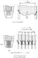
도 2는 기판 처리 장치를 나타낸 단면도이고, 도 3은 기판 처리 장치 각각에 제공되는 처리액 분사 유닛을 보여주는 구성도이다.Fig. 2 is a sectional view showing the substrate processing apparatus, and Fig. 3 is a configuration diagram showing a processing liquid spraying unit provided in each of the substrate processing apparatuses.
아래의 실시예에서는 처리액들을 사용하여 기판을 세정하는 장치를 예로 들어 설명한다. 그러나 본 발명의 기술적 사상은 이에 한정되지 않으며, 식각 공정 등과 같이 기판으로 처리액을 공급하면서 공정을 수행하는 다양한 종류의 장치에 모두 적용될 수 있다.In the following embodiments, an apparatus for cleaning a substrate using processing solutions is described as an example. However, the technical idea of the present invention is not limited thereto, and can be applied to various kinds of apparatuses that perform a process while supplying a process liquid to a substrate, such as an etching process.
또한, 본 실시예에서는 기판 처리 장치(60)가 처리하는 기판으로 반도체 기판을 일례로 도시하고 설명하였으나, 본 발명은 이에 한정되지 않고, 유리 기판과 같은 다양한 종류의 기판에도 적용될 수 있다.In the present embodiment, the substrate processed by the
도 2 및 도 3을 참조하면, 기판 처리 장치(60)는 공정 챔버(700), 처리 용기(100), 기판 지지부재(200) 그리고 처리액 분사 유닛(300)을 포함한다.2 and 3, the
공정 챔버(700)는 밀폐된 공간을 제공하며. 상부에는 팬 필터 유닛(710)이 설치된다. 팬 필터 유닛(710)은 공정챔버(700) 내부에 수직 기류를 발생시킨다.The
팬 필터 유닛(710)은 필터와 공기공급팬이 하나의 유니트로 모듈화된 것으로, 청정공기를 필터링하여 공정 챔버(700) 내부로 공급해주는 장치이다. 청정공기는 팬 필터 유닛(710)을 통과하여 공정 챔버(700) 내부로 공급되어 수직기류를 형성하게 된다. 이러한 공기의 수직기류는 기판 상부에 균일한 기류를 제공하게 되며, 처리액에 의해 기판 표면이 처리되는 과정에서 발생되는 퓸(Fume)등 오염기체는 공기와 함께 처리 용기(100)의 회수 용기들을 통해 배기부재(400)로 배출되어 제거됨으로써 처리 용기 내부의 청정도를 유지하게 된다.The
공정 챔버(700)는 수평 격벽(714)에 의해 공정 영역(716)과 유지보수 영역(718)으로 구획된다. 도면에는 일부만 도시하였지만, 유지보수 영역(718)에는 처리 용기(100)와 연결되는 회수라인(141,145), 서브배기라인(410) 이외에도 처리액 분사 유닛(300)의 분사 노즐(320)과 연결되는 처리액 공급라인 등이 위치되는 공간으로, 이러한 유지보수 영역(718)은 기판 처리가 이루어지는 공정 영역으로부터 격리되는 것이 바람직하다.The
처리 용기(100)는 상부가 개구된 원통 형상을 갖고, 기판(w)을 처리하기 위한 공정 공간을 제공한다. 처리 용기(100)의 개구된 상면은 기판(w)의 반출 및 반입 통로로 제공된다. 공정 공간에는 기판 지지부재(200)가 위치된다. 처리 용기(100)는 공정 공간 아래에 제2배기부재(400)와 연결되는 제2배기덕트(190)가 제공된다. 제2배기덕트(190)는 바닥면에 드레인 라인(192)이 제공된다.The
처리 용기(100)는 회수통들(121,122,123)과 제1승강 부재(130)를 포함한다.The
회수통(121,122,123)들은 회전되는 기판상에서 비산되는 약액과 기체를 유입 및 흡입하기 위해 다단으로 배치된다. 각각의 회수통(121,122,123)은 공정에 사용된 처리액 중 서로 상이한 처리액을 회수할 수 있다.The
제3고정 회수통(123)은 기판 지지부재(311)를 감싸는 환형의 링 형상으로 제공되고, 제2고정 회수통(122)은 제3고정 회수통(123)을 감싸는 환형의 링 형상으로 제공되고, 제1고정 회수통(121)은 제2고정 회수통(122)을 감싸는 환형의 링 형상으로 제공된다. 제3고정 회수통(123)의 내측 공간(123a)은 제3고정 회수통(123)으로 약액과 기체가 유입되는 유입구로서 제공된다. 제3고정 회수통(123)과 제2고정 회수통(122)의 사이 공간(122a)은 제2고정 회수통(122)으로 약액과 기체가 유입되는 유입구로서 제공된다. 그리고, 제2고정 회수통(122)과 제1고정 회수통(121)의 사이 공간은 제1고정 회수통(121)으로 약액과 기체가 유입되는 유입구로서 제공된다.The third
본 실시예에서, 처리 용기는 3개의 고정 회수통을 갖는 것으로 도시하였으나, 이에 한정되지 않으며, 상기 처리용기는 2개의 고정 회수통 또는 3개 이상의 고정 회수통을 포함할 수 있다.In this embodiment, the processing vessel is shown as having three fixed recovery cylinders, but the present invention is not limited thereto. The processing vessel may include two fixed recovery cylinders or three or more fixed recovery cylinders.
배기 부재(400)는 기판 처리 공정시 처리 용기(100) 내에 배기압력을 제공하기 위한 것이다. 제2배기부재(400)는 제2배기덕트(190)와 연결되는 서브 배기 라인(410), 댐퍼(420)를 포함한다. 서브 배기 라인(410)은 배기펌프(미도시됨)로부터 배기압을 제공받으며 반도체 생산라인의 바닥 공간에 매설된 메인 배기 라인과 연결된다.The
기판 지지부재(200)는 공정 진행 중 기판(W)을 지지하고 기판을 회전시킨다. 기판 지지부재(200)는 스핀 헤드(210), 지지축(220), 회전 구동부(230)을 포함한다. 스핀 헤드는 지지핀(212), 척핀(214)을 포함한다. 스핀 헤드(210)는 상부에서 바라볼 때 대체로 원형으로 제공되는 상부면을 가진다. 스핀 헤드(210)의 저면에는 회전구동부(230)에 의해 회전가능한 지지축(220)이 고정결합된다.The
처리액 분사 유닛(300)은 기판 지지부재(200)의 스핀헤드(210)에 놓인 기판의 처리면으로 처리액을 분사한다.The processing
처리액 분사 유닛(300)는 처리액의 유동 경로를 제공하는 처리액 공급라인(302)과 처리액 공급 라인(302)과 연결되어 처리액을 토출시키는 분사 노즐(320)을 갖는 분사 부재(310)를 포함할 수 있다.The treatment
처리액 공급라인(302)에는 석백(SuckBack) 밸브(304) 그리고 유량 on/off 기능을 갖는 밸브(306)가 설치될 수 있다. A
분사 부재(310)는 지지축(312), 구동기(314), 노즐 지지대(316) 그리고 분사 노즐(320)을 포함할 수 있다. 지지축(312)은 그 길이 방향이 제 3 방향(3)으로 제공되며, 지지축(312)의 하단은 구동기(314)와 결합된다. 구동기(314)는 지지축(312)을 회전 및 직선 운동시킨다. 노즐 지지대(316)는 지지축(312)에 결합되어 분사 노즐(320)을 기판 상부로 이동시키거나, 기판 상부에서 분사 노즐(320)이 처리액을 분사하면서 이동되도록 한다.The
분사 노즐(320)은 노즐 지지대(316)의 끝단 저면에 설치될 수 있다. 분사 노즐(320)은 구동기(314)에 의해 공정 위치와 대기 위치로 이동될 수 있다. 공정 위치는 분사 노즐(320)이 처리 용기(100)의 수직 상부에 배치된 위치이고, 대기위치는 분사 노즐(320)이 처리 용기(100)의 수직 상부로부터 벗어난 위치이다. 분사 노즐(320)은 처리액 공급 라인(302)으로부터 공급된 처리액을 분사한다. 또한, 분사 노즐(320)은 처리액 공급 라인(302)에서 공급된 처리액 외에 다른 처리액을 직접 노즐로 공급받아 분사할 수 있다.The
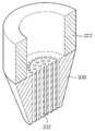
도 4는 분사 노즐의 측단면도이고, 도 5는 분사 노즐의 요부 확대도이며, 도 6은 기존 분사 노즐과 본 발명의 분사 노즐의 포스 분포를 분석한 도면이다.FIG. 4 is a side sectional view of the injection nozzle, FIG. 5 is an enlarged view of the main part of the injection nozzle, and FIG. 6 is an analysis of the force distribution of the conventional injection nozzle and the injection nozzle of the present invention.
도 4 내지 도 6을 참조하면, 분사 노즐의 노즐 몸체는 처리액을 수용하는 내부 공간과 내부공간과 연결되어 처리액을 하방으로 토출하는 미세홀들을 포함한다.4 to 6, the nozzle body of the injection nozzle includes an inner space for receiving the process liquid and fine holes connected to the inner space to discharge the process liquid downward.
도 6에서와 같이, 기존 분사 노즐과 본 발명의 분사 노즐의 force 분포를 분석하면 다음과 같다. 우선, 수식에서 F=adhesion force, σ=surface tension, θ=contact angle 을 의미한다.As shown in FIG. 6, the force distribution of the conventional injection nozzle and the injection nozzle of the present invention is analyzed as follows. First, in the equation, F = adhesion force, σ = surface tension, and θ = contact angle.
위쪽 그림은 1/4" 단일 분사공을 갖는 기존 분사 노즐(이하 단일 노즐이라고 함)을 예를 든 것이고, 아래쪽 그림은 Φ0.5 홀이 63개의 분사공(미세홀)들이 뚫린 본 발명의 분사 노즐(이하 다공 노즐이라고 함)을 예를 든 것이다.The upper drawing is an example of a conventional injection nozzle having a 1/4 "single injection hole (hereinafter referred to as a single nozzle), and the lower drawing is an example of an injection of the present invention in which a hole A nozzle (hereinafter referred to as a porous nozzle) is exemplified.
단일 노즐의 단면적은 12.24mm2, 다공노즐의 단면적은 12.36mm2으로 거의 유사하다. 응착력(Adhesion force)는 처리액과 분사공의 접착 계면 길이(πD)에 비례 하게 되는데, 다공노즐의 경우 그 길이가 크게 늘어나게 된다. 결과적으로 약 8배의 응착력(adhesion force)을 갖게 되어 처리액 드롭을 효과적으로 방지 할 수 있게 된다.The cross-sectional area of a single nozzle is approximately 12.24
도 7은 미세홀들의 다양한 예를 보여주는 도면들이다.Fig. 7 is a view showing various examples of the fine holes.
도 7에서와 같이, 분사 노즐(320)의 미세홀(332)들은 그 단면형상이 원형이거나 또는 다각형으로 제공될 수 있다. 특히, 육각형의 단면을 갖는 미세홀들의 경우 미세홀들 간의 간격을 조밀하게 제공할 수 있고, 또한 미세홀(332)들 간의 간격을 일정하게 제공할 수 있다. 즉, 미세홀들 간의 간격이 줄어들어 처리액이 뭉쳐서 하나의 줄기를 이룰 수 있는 각별한 효과가 있다.7, the
도 8을 참조하면, 미세홀들은 미세홀 지름(D)보다 작은 간격으로 제공될 수 있다. 다시 말해, 미세홀들 중심간의 간격(L1)이 미세홀 지름(D)의 2배 이하로 제공되는 것이 바람직하다.Referring to FIG. 8, the fine holes may be provided at intervals smaller than the fine hole diameter D. In other words, it is preferable that the interval L1 between the centers of the fine holes is provided not more than twice the diameter D of the fine holes.
분사 노즐(320)은 미세홀(332)을 가공하는 과정에서 노즐 끝 부분의 형태를 일정하게 유지하는 것이 어렵고, 만약 끝 부분의 가공이 불완전한 경우 처리액이 갈라져서 분사되는 현상이 발생될 수 있다. 처리액이 갈라져서 분사되는 문제는 아래와 같은 분사 노즐의 구조 변경을 통해 해결할 수 있다.It is difficult for the
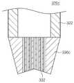
도 9는 처리액의 갈라짐 현상을 방지할 수 있는 분사 노즐의 제1변형예를 보여주는 도면이다.Fig. 9 is a view showing a first modification of the injection nozzle capable of preventing cracking of the processing liquid. Fig.
도 9를 참조하면, 분사 노즐(320a)은 가장자리에 위치하는 미세홀(332a)들을 처리액이 중앙으로 모일 수 있도록 노즐 몸체(322)의 중심부 방향으로 경사지게 제공된다. 즉, 분사 노즐(320a)은 최외각 미세홀(332a)들과 중앙 미세홀(332)들로 구분하고, 중앙 미세홀(332)들은 수직하게 가공하고, 최외각 미세홀(332a)들은 중심부 방향으로 경사지게 가공하여 처리액이 중앙으로 모여 분사될 수 있도록 하였다.Referring to FIG. 9, the
도 10은 처리액의 갈라짐 현상을 방지할 수 있는 분사 노즐의 제2변형예를 보여주는 도면이다.Fig. 10 is a view showing a second modification of the injection nozzle capable of preventing cracking of the processing liquid. Fig.
도 10을 참조하면, 분사 노즐(320b)은 단부에 해당되는 노즐팁(330b)의 형상을 변경하여 처리액의 갈라짐 현상을 방지할 수 있다. 분사 노즐(320b)은 외곽에서 중심방향으로 오목하게 형성한 노즐팁(330b)을 가짐으로써 미세홀(332)들을 통해 분사되는 처리액을 중앙으로 모여 분사될 수 있도록 하였다.Referring to FIG. 10, the shape of the
도 11은 처리액의 갈라짐 현상을 방지할 수 있는 분사 노즐의 제3변형예를 보여주는 도면이다.11 is a view showing a third modification of the injection nozzle capable of preventing cracking of the processing liquid.
도 11을 참조하면, 분사 노즐(320c)은 단부에 해당되는 노즐팁(330c)의 형상을 변경하여 처리액의 갈라짐 현상을 방지할 수 있다. 분사 노즐(320c)은 중심에서 외곽방향으로 하향경사지게 형성한 노즐팁(330c)을 가짐으로써 미세홀(332)들을 통해 분사되는 처리액을 중앙으로 모여 분사될 수 있도록 하였다.11, the shape of the
도 12는 분사 노즐의 제4변형예를 보여주는 도면이다.12 is a view showing a fourth modified example of the injection nozzle.
도 12에서와 같이, 분사 노즐(320d)의 노즐팁(330d)은 볼록한 형태로 제공될 수 있다.As shown in Fig. 12, the
도 13은 분사 노즐의 제5변형예를 보여주는 도면이다.13 is a view showing a fifth modification of the injection nozzle.
분사 노즐(320e)는 가이드(392)를 포함할 수 있다. 가이드(392)는 미세홀(332)들을 통해 분사되는 처리액이 주위로 퍼지지 않도록 노즐팁(330)의 가장자리에 설치된다.The
이상의 설명은 본 발명의 기술 사상을 예시적으로 설명한 것에 불과한 것으로서, 본 발명이 속하는 기술 분야에서 통상의 지식을 가진 자라면 본 발명의 본질적인 특성에서 벗어나지 않는 범위에서 다양한 수정 및 변형이 가능할 것이다. 따라서, 본 발명에 개시된 실시 예들은 본 발명의 기술 사상을 한정하기 위한 것이 아니라 설명하기 위한 것이고, 이러한 실시 예에 의하여 본 발명의 기술 사상의 범위가 한정되는 것은 아니다. 본 발명의 보호 범위는 아래의 청구범위에 의하여 해석되어야 하며, 그와 동등한 범위 내에 있는 모든 기술 사상은 본 발명의 권리범위에 포함되는 것으로 해석되어야 할 것이다.The foregoing description is merely illustrative of the technical idea of the present invention, and various changes and modifications may be made by those skilled in the art without departing from the essential characteristics of the present invention. Therefore, the embodiments disclosed in the present invention are intended to illustrate rather than limit the scope of the present invention, and the scope of the technical idea of the present invention is not limited by these embodiments. The scope of protection of the present invention should be construed according to the following claims, and all technical ideas within the scope of equivalents should be construed as falling within the scope of the present invention.
700: 공정 챔버100 : 처리 용기
200 : 기판 지지부재300 : 처리액 분사 유닛700: process chamber 100: processing vessel
200: substrate supporting member 300: process liquid spraying unit
Claims (13)
Translated fromKorean내부에 공정을 수행하는 처리 공간이 형성된 하우징;
상기 처리공간에서 기판을 지지 및 회전시키는 스핀헤드; 그리고
상기 스핀헤드에 지지된 기판 상으로 처리액을 공급하는 분사 노즐을 갖는 처리액 분사 유닛을 포함하되,
상기 분사 노즐은
처리액을 수용하는 내부 공간을 제공하는 노즐 몸체; 및 상기 노즐 몸체 하단에 제공되고 상기 내부 공간과 연결되어 상기 처리액을 하방으로 토출하는 미세홀들을 갖는 노즐 팁을 포함하며,
상기 미세홀들을 통과한 처리액이 상기 노즐 팁의 중심으로 모이도록, 상기 노즐 팁의 상기 미세홀들의 하단부는 상기 노즐 팁의 외곽에서 중심방향으로 오목하게 형성되고, 상기 미세홀들은 기판 표면에 대해 수직하게 형성되는 것을 특징으로 하는 기판 처리 장치.In the substrate processing apparatus,
A housing having a processing space for performing a process therein;
A spin head for supporting and rotating the substrate in the processing space; And
And a processing liquid injection unit having an injection nozzle for supplying the processing liquid onto the substrate supported by the spin head,
The injection nozzle
A nozzle body for providing an internal space for accommodating the treatment liquid; And a nozzle tip provided at a lower end of the nozzle body and connected to the inner space to have fine holes for discharging the processing liquid downward,
The lower end of the fine holes of the nozzle tip is concaved in the center direction at the outer periphery of the nozzle tip so that the processing liquid passing through the fine holes collects at the center of the nozzle tip, And is vertically formed.
내부에 공정을 수행하는 처리 공간이 형성된 하우징;
상기 처리공간에서 기판을 지지 및 회전시키는 스핀헤드; 그리고
상기 스핀헤드에 지지된 기판 상으로 처리액을 공급하는 분사 노즐을 갖는 처리액 분사 유닛을 포함하되,
상기 분사 노즐은
처리액을 수용하는 내부 공간을 제공하는 노즐 몸체; 및 상기 노즐 몸체 하단에 제공되고 상기 내부공간과 연결되어 처리액을 기판을 향하여 하방으로 토출하는 미세홀들을 갖는 노즐 팁을 포함하며,
상기 미세홀들을 통과한 처리액이 뭉쳐져서 상기 기판으로 토출되도록, 상기 미세홀들은
상호간의 간격은 동일하고, 횡단면 형상이 육각형인 것을 특징으로 하는 기판 처리 장치.In the substrate processing apparatus,
A housing having a processing space for performing a process therein;
A spin head for supporting and rotating the substrate in the processing space; And
And a processing liquid injection unit having an injection nozzle for supplying the processing liquid onto the substrate supported by the spin head,
The injection nozzle
A nozzle body for providing an internal space for accommodating the treatment liquid; And a nozzle tip provided at a lower end of the nozzle body and connected to the inner space, the nozzle tip having fine holes for discharging the processing liquid downward toward the substrate,
So that the treatment liquid that has passed through the fine holes collects and is discharged to the substrate,
Wherein a gap between the substrates is the same, and the cross-sectional shape is hexagonal.
상기 미세홀들 상호간의 간격은 동일한 것을 특징으로 하는 기판 처리 장치.The method according to claim 1,
And the spacing between the fine holes is the same.
상기 미세홀들 상호간의 간격은
상기 미세홀의 폭의 2배 이하인 것을 특징으로 하는 기판 처리 장치.4. The method according to any one of claims 1 to 3,
The interval between the fine holes
And the width of the fine holes is not more than twice the width of the fine holes.
상기 분사 노즐은
상기 미세홀들을 통해 분사되는 처리액이 주위로 퍼지지 않도록 상기 노즐팁의 가장자리에 제공되는 가이드를 더 포함하는 것을 특징으로 하는 기판 처리 장치.4. The method according to any one of claims 1 to 3,
The injection nozzle
Further comprising a guide provided at an edge of the nozzle tip so as to prevent the treatment liquid sprayed through the fine holes from spreading to the surroundings.
처리액의 유동 경로를 제공하는 처리액 공급라인; 및
상기 처리액 공급 라인에 설치되어 처리액을 토출시키는 분사 노즐을 포함하되;
상기 분사 노즐은
처리액이 흐르는 액 라인을 갖는 노즐 몸체 및 상기 액 라인과 연결되어 상기 처리액을 하방으로 토출하는 미세홀들을 갖는 노즐팁을 포함하며,
상기 노즐 팁의 상기 미세홀들의 하단부는
상기 미세홀들을 통과한 처리액이 서로 하나로 뭉쳐 하나의 줄기를 이루도록, 상기 노즐 팁의 외곽에서 중심방향으로 오목하게 형성되고, 상기 미세홀들은 기판 표면에 대해 수직하게 형성되는 것을 특징으로 하는 처리액 분사 유닛.A treatment liquid spraying unit comprising:
A processing liquid supply line for providing a flow path of the processing liquid; And
And a spray nozzle installed on the treatment liquid supply line to discharge the treatment liquid;
The injection nozzle
A nozzle body having a liquid line through which the process liquid flows and a nozzle tip connected to the liquid line and having fine holes for discharging the process liquid downward,
The lower ends of the fine holes of the nozzle tip
Characterized in that the treatment liquid which has passed through the fine holes is formed concavely in the center direction at the outer periphery of the nozzle tip so as to form a single stem, Injection unit.
상기 처리액 공급 라인에 설치되는 석백(suck-back) 밸브 그리고 유량 온오프 밸브를 더 포함하는 특징으로 하는 처리액 분사 유닛.The method according to claim 6,
A suck-back valve installed in the processing solution supply line, and a flow rate on-off valve.
처리액의 유동 경로를 제공하는 처리액 공급라인; 및
상기 처리액 공급 라인에 설치되어 처리액을 기판으로 토출시키는 분사 노즐을 포함하되;
상기 분사 노즐은
처리액이 흐르는 액 라인을 갖는 노즐 몸체 및 상기 액 라인과 연결되어 상기 처리액을 상기 기판을 향하여 하방으로 토출하는 미세홀들을 갖는 노즐 팁을 포함하며,
상기 미세홀들을 통과한 처리액이 뭉쳐져서 상기 기판으로 토출되도록, 상기 미세홀들은
상호간의 간격은 동일하고,
횡단면 형상이 육각형인 것을 특징으로 하는 처리액 분사 유닛.A treatment liquid spraying unit comprising:
A processing liquid supply line for providing a flow path of the processing liquid; And
And a spray nozzle installed on the treatment liquid supply line and discharging the treatment liquid onto the substrate;
The injection nozzle
A nozzle body having a liquid line through which a process liquid flows and a nozzle tip connected to the liquid line and having fine holes for discharging the process liquid downward toward the substrate,
So that the treatment liquid that has passed through the fine holes collects and is discharged to the substrate,
The intervals between them are the same,
And the cross-sectional shape is a hexagonal shape.
상기 미세홀들 상호간의 간격은
상기 미세홀의 폭의 2배 이하인 것을 특징으로 하는 처리액 분사 유닛.9. The method according to any one of claims 6 to 8,
The interval between the fine holes
And the width of the fine holes is not more than twice the width of the fine holes.
내부에 처리액이 흐르는 액 라인이 형성된 노즐 몸체 및 상기 액 라인으로부터 연장되며 복수의 미세홀들을 갖는 노즐팁을 가지는 분사 노즐;
상기 분사 노즐에 연결되며 상기 노즐 몸체로 액을 공급하는 처리액 공급라인;
상기 처리액 공급라인에 설치되며, 상기 분사 노즐에 잔류하는 액을 상기 노즐팁으로부터 멀어지는 방향으로 흡입하는 석백밸브를 포함하되;
상기 미세홀들을 통과한 처리액이 상기 노즐 팁의 중심으로 모이도록, 상기 노즐 팁의 상기 미세홀들의 하단부는
상기 미세홀들을 통과한 처리액이 서로 하나로 뭉쳐 하나의 줄기를 이루도록 상기 노즐 팁의 외곽에서 중심 방향으로 오목하게 형성되고, 상기 미세홀들은 기판 표면에 대해 수직하게 형성되는 처리액 분사 유닛.A process liquid spray unit for supplying a process liquid to a substrate,
A spray nozzle having a nozzle body having a liquid line through which a process liquid flows and a nozzle tip extending from the liquid line and having a plurality of fine holes;
A processing liquid supply line connected to the injection nozzle and supplying the liquid to the nozzle body;
A quartz valve installed in the treatment liquid supply line and sucking the liquid remaining in the injection nozzle in a direction away from the nozzle tip;
And a lower end of the fine holes of the nozzle tip is positioned at a center of the nozzle tip,
Wherein the processing solution passing through the fine holes is formed concavely in the center of the outer periphery of the nozzle tip so as to form a single stem, and the fine holes are formed perpendicular to the substrate surface.
내부에 처리액이 흐르는 액 라인이 형성된 노즐 몸체 및 상기 액 라인으로부터 연장되며 복수의 미세홀들을 갖는 노즐팁을 가지는 분사 노즐;
상기 분사 노즐에 연결되며 상기 노즐 몸체로 액을 공급하는 처리액 공급라인;
상기 처리액 공급라인에 설치되며, 상기 분사 노즐에 잔류하는 액을 상기 노즐팁으로부터 멀어지는 방향으로 흡입하는 석백밸브를 포함하되;
상기 미세홀들을 통과한 처리액이 뭉쳐져서 상기 기판으로 토출되도록, 상기 미세홀들은 상호간의 간격은 동일하고, 횡단면은 육각형의 형상으로 제공되는 처리액 분사 유닛.A process liquid spray unit for supplying a process liquid to a substrate,
A spray nozzle having a nozzle body having a liquid line through which a process liquid flows and a nozzle tip extending from the liquid line and having a plurality of fine holes;
A processing liquid supply line connected to the injection nozzle and supplying the liquid to the nozzle body;
A quartz valve installed in the treatment liquid supply line and sucking the liquid remaining in the injection nozzle in a direction away from the nozzle tip;
Wherein the fine holes are provided in a hexagonal shape so that a distance between the fine holes is the same and a cross section is formed in a hexagonal shape so that a processing solution having passed through the fine holes is collected and discharged to the substrate.
상기 액은 이소프로필 알코올을 포함하는 처리액 분사 유닛.The method according to claim 10 or 11,
Wherein the liquid comprises isopropyl alcohol.
상기 액은 오존을 포함하는 처리액 분사 유닛.The method according to claim 10 or 11,
Wherein the liquid includes ozone.
Priority Applications (1)
| Application Number | Priority Date | Filing Date | Title |
|---|---|---|---|
| KR1020170149727AKR101884852B1 (en) | 2017-11-10 | 2017-11-10 | Chemical nozzle and apparatus for treating substrate |
Applications Claiming Priority (1)
| Application Number | Priority Date | Filing Date | Title |
|---|---|---|---|
| KR1020170149727AKR101884852B1 (en) | 2017-11-10 | 2017-11-10 | Chemical nozzle and apparatus for treating substrate |
Related Parent Applications (1)
| Application Number | Title | Priority Date | Filing Date |
|---|---|---|---|
| KR1020160052951ADivisionKR101817212B1 (en) | 2016-04-29 | 2016-04-29 | Chemical nozzle and apparatus for treating substrate |
Publications (2)
| Publication Number | Publication Date |
|---|---|
| KR20170128188A KR20170128188A (en) | 2017-11-22 |
| KR101884852B1true KR101884852B1 (en) | 2018-08-02 |
Family
ID=60809780
Family Applications (1)
| Application Number | Title | Priority Date | Filing Date |
|---|---|---|---|
| KR1020170149727AActiveKR101884852B1 (en) | 2017-11-10 | 2017-11-10 | Chemical nozzle and apparatus for treating substrate |
Country Status (1)
| Country | Link |
|---|---|
| KR (1) | KR101884852B1 (en) |
Families Citing this family (1)
| Publication number | Priority date | Publication date | Assignee | Title |
|---|---|---|---|---|
| CN108389818A (en)* | 2018-05-14 | 2018-08-10 | 安徽宏实自动化装备有限公司 | A kind of wet process equipment dynamic etch liquid uniforming device |
Citations (5)
| Publication number | Priority date | Publication date | Assignee | Title |
|---|---|---|---|---|
| JP2004016878A (en)* | 2002-06-13 | 2004-01-22 | Shibaura Mechatronics Corp | Substrate processing apparatus and processing liquid supply nozzle apparatus |
| JP3845424B2 (en) | 2003-04-30 | 2006-11-15 | ヒューレット−パッカード デベロップメント カンパニー エル.ピー. | Inkjet print head |
| JP2008126200A (en) | 2006-11-24 | 2008-06-05 | Taco Co Ltd | Nozzle device |
| WO2016025187A1 (en)* | 2014-08-15 | 2016-02-18 | Applied Materials, Inc. | Nozzle for uniform plasma processing |
| JP2016032107A (en)* | 2014-07-25 | 2016-03-07 | サムスン エレクトロニクス カンパニー リミテッド | Method for manufacturing semiconductor element and substrate processing method |
Family Cites Families (3)
| Publication number | Priority date | Publication date | Assignee | Title |
|---|---|---|---|---|
| KR101016921B1 (en)* | 2004-08-20 | 2011-02-28 | 주성엔지니어링(주) | Shower head |
| KR101034507B1 (en)* | 2008-10-31 | 2011-05-17 | 세메스 주식회사 | Processing liquid supply unit, substrate processing apparatus and method using same |
| KR101061614B1 (en) | 2009-12-21 | 2011-09-01 | 주식회사 케이씨텍 | Nozzle Unit of Cleaning Equipment |
- 2017
- 2017-11-10KRKR1020170149727Apatent/KR101884852B1/enactiveActive
Patent Citations (5)
| Publication number | Priority date | Publication date | Assignee | Title |
|---|---|---|---|---|
| JP2004016878A (en)* | 2002-06-13 | 2004-01-22 | Shibaura Mechatronics Corp | Substrate processing apparatus and processing liquid supply nozzle apparatus |
| JP3845424B2 (en) | 2003-04-30 | 2006-11-15 | ヒューレット−パッカード デベロップメント カンパニー エル.ピー. | Inkjet print head |
| JP2008126200A (en) | 2006-11-24 | 2008-06-05 | Taco Co Ltd | Nozzle device |
| JP2016032107A (en)* | 2014-07-25 | 2016-03-07 | サムスン エレクトロニクス カンパニー リミテッド | Method for manufacturing semiconductor element and substrate processing method |
| WO2016025187A1 (en)* | 2014-08-15 | 2016-02-18 | Applied Materials, Inc. | Nozzle for uniform plasma processing |
Also Published As
| Publication number | Publication date |
|---|---|
| KR20170128188A (en) | 2017-11-22 |
Similar Documents
| Publication | Publication Date | Title |
|---|---|---|
| KR101817212B1 (en) | Chemical nozzle and apparatus for treating substrate | |
| CN102610488B (en) | Liquid treatment device and liquid treatment method | |
| CN102629563B (en) | Liquid processing apparatus and liquid processing method | |
| KR102348772B1 (en) | Substrate processing apparatus, method of cleaning substrate processing apparatus, and storage medium | |
| US10825699B2 (en) | Standby port and substrate processing apparatus having the same | |
| KR101776019B1 (en) | Nozzle and Apparatus for treating Substrate with the nozzle | |
| KR20070072385A (en) | Substrate cleaning device and method | |
| US7412981B2 (en) | Liquid processing apparatus and method | |
| JP4889331B2 (en) | Substrate processing apparatus and substrate processing method | |
| CN107851572A (en) | Substrate processing apparatus, substrate processing method, and storage medium | |
| KR101884852B1 (en) | Chemical nozzle and apparatus for treating substrate | |
| JP2009117826A (en) | Substrate processing apparatus and method | |
| KR102596506B1 (en) | A home pot and an apparatus for treating a substrate | |
| KR102410311B1 (en) | method and Apparatus for Processing Substrate | |
| KR102239518B1 (en) | home port and substrate processing apparatus having the same | |
| KR20150138929A (en) | Apparatus for supplying fluid | |
| JP4339299B2 (en) | Resist coating device | |
| KR101582566B1 (en) | Apparatus and method for treating a substrate | |
| KR20130125165A (en) | Apparatus for processing substrate | |
| KR101899915B1 (en) | gate door unit and Apparatus for Processing Substrate | |
| KR101853372B1 (en) | Chemical nozzle and apparatus for treating substrate | |
| KR101885103B1 (en) | Injection Unit and Apparatus for treating Substrate with the same | |
| KR20170020022A (en) | Substrate treating method for selectively etching a substrate surfaces | |
| KR20250007115A (en) | Directional control valve | |
| KR20160005462A (en) | Apparatus and method for treating a subtrate |
Legal Events
| Date | Code | Title | Description |
|---|---|---|---|
| A107 | Divisional application of patent | ||
| A201 | Request for examination | ||
| PA0107 | Divisional application | Comment text:Divisional Application of Patent Patent event date:20171110 Patent event code:PA01071R01D Filing date:20160429 Application number text:1020160052951 | |
| PA0201 | Request for examination | ||
| PG1501 | Laying open of application | ||
| E902 | Notification of reason for refusal | ||
| PE0902 | Notice of grounds for rejection | Comment text:Notification of reason for refusal Patent event date:20171218 Patent event code:PE09021S01D | |
| E701 | Decision to grant or registration of patent right | ||
| PE0701 | Decision of registration | Patent event code:PE07011S01D Comment text:Decision to Grant Registration Patent event date:20180625 | |
| PR0701 | Registration of establishment | Comment text:Registration of Establishment Patent event date:20180727 Patent event code:PR07011E01D | |
| PR1002 | Payment of registration fee | Payment date:20180730 End annual number:3 Start annual number:1 | |
| PG1601 | Publication of registration | ||
| PR1001 | Payment of annual fee | Payment date:20210701 Start annual number:4 End annual number:4 | |
| PR1001 | Payment of annual fee | Payment date:20220624 Start annual number:5 End annual number:5 | |
| PR1001 | Payment of annual fee | Payment date:20230628 Start annual number:6 End annual number:6 | |
| PR1001 | Payment of annual fee | Payment date:20240625 Start annual number:7 End annual number:7 | |
| PR1001 | Payment of annual fee | Payment date:20250625 Start annual number:8 End annual number:8 |