KR101884781B1 - Three dimensional scanning system - Google Patents
Three dimensional scanning systemDownload PDFInfo
- Publication number
- KR101884781B1 KR101884781B1KR1020150170694AKR20150170694AKR101884781B1KR 101884781 B1KR101884781 B1KR 101884781B1KR 1020150170694 AKR1020150170694 AKR 1020150170694AKR 20150170694 AKR20150170694 AKR 20150170694AKR 101884781 B1KR101884781 B1KR 101884781B1
- Authority
- KR
- South Korea
- Prior art keywords
- light
- reflected
- optical
- point
- module
- Prior art date
- Legal status (The legal status is an assumption and is not a legal conclusion. Google has not performed a legal analysis and makes no representation as to the accuracy of the status listed.)
- Active
Links
Images


Classifications
- G—PHYSICS
- G01—MEASURING; TESTING
- G01S—RADIO DIRECTION-FINDING; RADIO NAVIGATION; DETERMINING DISTANCE OR VELOCITY BY USE OF RADIO WAVES; LOCATING OR PRESENCE-DETECTING BY USE OF THE REFLECTION OR RERADIATION OF RADIO WAVES; ANALOGOUS ARRANGEMENTS USING OTHER WAVES
- G01S7/00—Details of systems according to groups G01S13/00, G01S15/00, G01S17/00
- G01S7/48—Details of systems according to groups G01S13/00, G01S15/00, G01S17/00 of systems according to group G01S17/00
- G01S7/481—Constructional features, e.g. arrangements of optical elements
- G01S7/4817—Constructional features, e.g. arrangements of optical elements relating to scanning
- G—PHYSICS
- G01—MEASURING; TESTING
- G01B—MEASURING LENGTH, THICKNESS OR SIMILAR LINEAR DIMENSIONS; MEASURING ANGLES; MEASURING AREAS; MEASURING IRREGULARITIES OF SURFACES OR CONTOURS
- G01B11/00—Measuring arrangements characterised by the use of optical techniques
- G01B11/24—Measuring arrangements characterised by the use of optical techniques for measuring contours or curvatures
- G—PHYSICS
- G01—MEASURING; TESTING
- G01S—RADIO DIRECTION-FINDING; RADIO NAVIGATION; DETERMINING DISTANCE OR VELOCITY BY USE OF RADIO WAVES; LOCATING OR PRESENCE-DETECTING BY USE OF THE REFLECTION OR RERADIATION OF RADIO WAVES; ANALOGOUS ARRANGEMENTS USING OTHER WAVES
- G01S17/00—Systems using the reflection or reradiation of electromagnetic waves other than radio waves, e.g. lidar systems
- G01S17/88—Lidar systems specially adapted for specific applications
- G01S17/89—Lidar systems specially adapted for specific applications for mapping or imaging
- G—PHYSICS
- G02—OPTICS
- G02B—OPTICAL ELEMENTS, SYSTEMS OR APPARATUS
- G02B26/00—Optical devices or arrangements for the control of light using movable or deformable optical elements
- G02B26/08—Optical devices or arrangements for the control of light using movable or deformable optical elements for controlling the direction of light
- G02B26/10—Scanning systems
- G02B26/105—Scanning systems with one or more pivoting mirrors or galvano-mirrors
- G—PHYSICS
- G02—OPTICS
- G02B—OPTICAL ELEMENTS, SYSTEMS OR APPARATUS
- G02B27/00—Optical systems or apparatus not provided for by any of the groups G02B1/00 - G02B26/00, G02B30/00
- G02B27/10—Beam splitting or combining systems
- G02B27/1006—Beam splitting or combining systems for splitting or combining different wavelengths
- G02B27/102—Beam splitting or combining systems for splitting or combining different wavelengths for generating a colour image from monochromatic image signal sources
- G02B27/104—Beam splitting or combining systems for splitting or combining different wavelengths for generating a colour image from monochromatic image signal sources for use with scanning systems
- G—PHYSICS
- G02—OPTICS
- G02B—OPTICAL ELEMENTS, SYSTEMS OR APPARATUS
- G02B27/00—Optical systems or apparatus not provided for by any of the groups G02B1/00 - G02B26/00, G02B30/00
- G02B27/10—Beam splitting or combining systems
- G02B27/1086—Beam splitting or combining systems operating by diffraction only
Landscapes
- Physics & Mathematics (AREA)
- General Physics & Mathematics (AREA)
- Engineering & Computer Science (AREA)
- Optics & Photonics (AREA)
- Computer Networks & Wireless Communication (AREA)
- Radar, Positioning & Navigation (AREA)
- Remote Sensing (AREA)
- Electromagnetism (AREA)
- Optical Radar Systems And Details Thereof (AREA)
Abstract
Translated fromKoreanDescription
Translated fromKorean본 발명은 3차원 스캐닝 시스템에 관한 것으로서, 더욱 상세하게는, 곡면 또는 평면형태의 미러가 일정한 속도로 빠르게 일방향으로 회전하는 방식의 스캐닝 메커니즘을 사용하여 광송신모듈에서 방출되는 출력광의 광축과 광수신모듈로 수신되는 반사광의 광축이 서로 일치되도록 송수신 광학계를 구성하고 송수신 펄스 레이저 광을 소정의 각도로 빠르게 스캐닝 하도록 광송신모듈과 광수신모듈을 배치 구성함에 따라 장치 구성을 콤팩트하게 구현할 수 있는 장점이 있으며, 이를 통해 장치 전체의 무게를 획기적으로 줄이고, 빠른 3차원 영상 획득 속도를 구현할 수 있는 3차원 스캐닝 시스템에 관한 것이다.The present invention relates to a three-dimensional scanning system, and more particularly, to a three-dimensional scanning system using a scanning mechanism in which a curved or planar mirror is rapidly rotated in one direction at a constant speed, The optical transmitter module and the optical receiver module are arranged to configure the transmission and reception optical system so that the optical axes of the reflected light received by the module are matched with each other and to quickly scan the transmission and reception pulse laser light at a predetermined angle. The present invention relates to a three-dimensional scanning system capable of dramatically reducing the overall weight of the apparatus and realizing a fast 3D image acquisition speed.
라이다(LIDAR - Light Detection And Ranging) 또는 레이다(LADAR - Laser Detection And Ranging)로 불리는 3차원 영상센서는 목표물을 향해 펄스 레이저광을 방출한 후 목표물에 반사되어 돌아오는 빛 에너지를 광 수신소자(Photo Detector)를 사용하여 포착하고 이를 전기적 신호로 변환함으로써, 목표물까지의 거리나 목표물의 이동속도 등을 산출할 수 있는 시스템이다.A three-dimensional image sensor called LIDAR (Light Detection And Ranging) or LADAR (Laser Detection And Ranging) emits pulsed laser light toward a target, Photo Detector), and converts it into an electric signal, so that the distance to the target and the moving speed of the target can be calculated.
이러한 라이다 시스템은 로봇 및 무인자동차의 전방 장애물 검출용 센서, 속도측정용 레이더 건, 항공 지오-맵핑장치, 3차원 지상조사, 수중 스캐닝 등 다양한 분야에서 널리 적용되고 있다.Such a lidar system is widely applied in a variety of fields such as a sensor for detecting obstacles in front of a robot and an unmanned vehicle, a radar gun for speed measurement, an aerial geo-mapping device, a three-dimensional ground survey, and an underwater scanning.
최근, 라이다 시스템은 전방 또는 측방의 장애물 등에 의한 위험 상황이 발생할 경우 운전자에게 경고하거나 자동차의 속도를 조절하는 조치를 자동적으로 수행할 수 있게 하는 운전 보조용 애플리케이션이나, 운전자 없이 운행하는 트랙터와 같은 자동 운전장치로 그 적용 분야가 확대되고 있다.In recent years, the Raida system has been used as a driving assistant application, which allows the driver to be alerted or to take measures to automatically adjust the speed of the vehicle in the event of a dangerous situation such as a frontal or lateral obstacle, The application field of the automatic operation device is expanding.
상술한 바와 같은 라이다 시스템의 일예로서, 본 출원인이 출원하여 등록받은 등록특허 제10-1357051호에 '3차원 스캐닝 시스템 및 이를 이용한 3차원 영상획득방법'이 개시된 바 있다.As an example of the above-described Lada system, a three-dimensional scanning system and a three-dimensional image acquisition method using the same are disclosed in Japanese Patent Application No. 10-1357051 filed and filed by the present applicant.
상기 3차원 스캐닝 시스템은, 펄스광을 방출한 후 목표물로부터 반사된 반사광을 수신하여 목표물의 거리를 산출하여 3차원 영상을 획득하는 스캐닝 시스템으로, 펄스레이저광을 생성하는 광원장치와, 상기 펄스레이저광을 방출하고 방출된 펄스레이저광의 반사광을 수신하는 광송수신모듈을 포함하는 광송수신수단와, 상기 광송수신수단을 회전 구동시키는 회전구동장치와, 상기 광원장치, 광송수신수단 및 회전구동장치를 제어하는 제어장치를 포함하고, 상기 광송수신수단은 2 이상의 광송수신모듈로 이루어지고, 상기 2 이상의 광송수신모듈 중 적어도 하나 이상의 광 방출각도가 다른 광송수신모듈과 상이하도록 구성된다.The three-dimensional scanning system includes a light source device for generating a pulsed laser beam, a scanning system for obtaining a three-dimensional image by calculating a distance of a target by receiving reflected light reflected from a target after emitting pulse light, An optical transmission / reception unit including an optical transmission / reception module for emitting light and receiving reflection of the emitted pulsed laser light; a rotation driving device for rotating the optical transmission / reception means; and a control unit for controlling the light source device, the optical transmission / reception means, Receiving module, wherein the optical transmitting and receiving means comprises two or more optical transmitting and receiving modules, and the at least one light emitting angle of the at least two optical transmitting and receiving modules is different from that of the other optical transmitting and receiving modules.
그런데, 상술한 바와 같은 상기 3차원 스캐닝 시스템은, 회전구동장치 상부에 펄스레이저 소스모듈과 광송수신수단을 모두 장착하여 회전시키는 구조로 되어 있어 다채널 구성으로 360°의 넓은 화각의 3차원 영상을 얻을 수 있다는 장점이 있으나, 3차원 스캐닝시스템의 회전부에 위치한 광수신 모듈, 광학계 부품, 신호처리 모듈, 펄스레이저 소스모듈과 전원공급 및 신호전송모듈 등 모든 구성부품들을 회전시켜야 하기 때문에 용량이 큰 회전모터가 필요하게 되고, 이는 결과적으로 스캐닝 시스템의 무게와 부피를 증가시키는 문제점이 있었다.The above-described three-dimensional scanning system has a structure in which both a pulsed laser source module and an optical transmitting / receiving means are mounted on a rotating driving device and rotated, and a three-dimensional image having a wide viewing angle of 360 ° However, since all the components such as the optical receiving module, the optical system part, the signal processing module, the pulse laser source module, the power supply and the signal transmission module located in the rotating part of the 3D scanning system must be rotated, A motor is required, which results in an increase in the weight and volume of the scanning system.
또한, 실선의 라인 레이저를 사용하여 조사거리가 수십 m 또는 수백 m 거리에서 높은 수준의 스캐닝 정보를 얻기 위해서는 사용하는 레이저 펄스광의 소스를 수백 와트에서 수천 와트 이상인 것을 사용하여야 하며, 이와 같이 높은 출력의 레이저 광을 생성하기 위해서는 레이저 소스인 광원장치의 크기와 무게가 커지고 소모되는 전원의 양의 많은 단점이 있으며, 이로 인한 발열량도 많아 스캐닝 센서를 설계하는데 있어서 많은 제약이 따르는 단점이 있었다.In order to obtain a high level of scanning information at a distance of several tens of meters or a few hundreds of meters using a solid line line laser, the source of the laser pulse light used should be several hundred watts to several thousands of watts or more. In order to generate a laser beam, the size and weight of the laser source, the size of the laser source, and the amount of power consumed are large, and the amount of heat generated by the laser source is large.
또한, 광송신모듈에서 방출되는 출력광의 광축과 광수신모듈로 수신되는 반사광의 광축이 서로 일치되지 않아 장치 구성이 증가되는 문제점이 있으며, 이와 같이, 출력광과 반사광의 광축이 서로 일치되지 않음에 따른 근거리 검출능력이 다소 떨어지는 단점이 있었다.Also, since the optical axis of the output light emitted from the optical transmitting module and the optical axis of the reflected light received by the optical receiving module are not aligned with each other, the configuration of the device is increased. There is a disadvantage in that the near-field detection capability is somewhat deteriorated.
한편, 독일에서 출원되어 공개된 공개특허 제10244641호(2004-04-08)에는 'Optoelectronic position monitoring system for road vehicle has two pulsed lasers, sensor and mechanical scanner with mirror at 45 degrees on shaft with calibration disk driven by electric motor'에 대해 개시되어 있다.In the meantime, in patent document No. 10244641 (2004-04-08) filed in Germany, 'Optoelectronic position monitoring system for road vehicle has two pulsed lasers, sensor and mechanical scanner with mirror at 45 degrees on shaft with calibration disk driven by electric motor '.
상기 공개특허에는 회전형의 평면 미러를 사용하고 중심에 하나 이상의 광수신수단을 위치시키고 양 끝단에 다수의 광송신수단을 위치시키는 형태의 동일한 광편향수단을 사용하는 전자광학 센서에 대해 개시되어 있다.The patent discloses an electro-optic sensor using the same type of planar mirror and using the same optical deflecting means in the form of positioning one or more light receiving means at the center and placing a plurality of light transmitting means at both ends .
하지만, 상기 공개특허에 개시된 상기 전자광학센서는 하나의 평면 미러를 사용하여 다채널의 거리영상신호를 얻을 수 있도록 구성되어 있으나, 발광축과 수광축이 분리되어 있어 근접거리의 물체를 검지하지 못하고 공간적으로 분리된 다수개의 광송신수단을 사용하기 때문에 채널수를 확장하는데 한계를 가지고 있다.However, although the electro-optical sensor disclosed in the above-mentioned patent is constructed so as to obtain a multi-channel distance image signal by using a single plane mirror, since the light emitting axis and the light receiving axis are separated, There are limitations in expanding the number of channels because a plurality of spatially separated optical transmission means are used.
독일공개특허 제10244641호(공개일자:2004년 4월 8일)German Patent Publication No. 10244641 (published on Apr. 8, 2004)
상기 종래 기술에 따른 문제점을 해결하기 위한 본 발명의 목적은, 곡면 또는 평면형태의 미러가 일정한 속도로 빠르게 일방향으로 회전하는 방식의 스캐닝 메커니즘을 사용하여 광송신모듈에서 방출되는 출력광의 광축과 광수신모듈로 수신되는 반사광의 광축이 서로 일치되도록 송수신 광학계를 구성하고 송수신 펄스 레이저 광을 소정의 각도로 빠르게 스캐닝 하도록 광송신모듈과 광수신모듈을 배치 구성함에 따라 장치 구성을 콤팩트하게 구현할 수 있는 장점이 있으며, 이를 통해 장치 전체의 무게를 획기적으로 줄이고, 빠른 3차원 영상 획득 속도를 구현할 수 있는 3차원 스캐닝 시스템을 제공함에 있다.An object of the present invention is to provide a scanning mechanism in which a curved surface or a flat mirror is rapidly rotated in one direction at a constant speed and the optical axis of the output light emitted from the optical transmitter module and the optical axis The optical transmitter module and the optical receiver module are arranged to configure the transmission and reception optical system so that the optical axes of the reflected light received by the module are matched with each other and to quickly scan the transmission and reception pulse laser light at a predetermined angle. Dimensional scanning system that can reduce the weight of the entire apparatus and realize a fast 3D image acquisition speed.
또한, 본 발명의 또다른 목적은, 실선(Solid Line)이 아닌 도트 라인(Dot Line) 형태의 다점 출력광을 방출한 후 목표물로부터 반사되어 돌아오는 반사광을 라인 배열형태의 광학 검출기인 광수신모듈로 검출하여 3차원 포인트 클라우드 데이터 영상을 형성함에 따라 광송신모듈의 출력광량을 줄여 저출력 광원을 이용하면서도 단위 스캐닝 픽셀 당 수신되는 광의 밀도를 높여 높은 수준의 거리영상신호를 얻을 수 있는 3차원 스캐닝 시스템을 제공함에 있다.It is a further object of the present invention to provide a light receiving module, which is an optical detector in the form of a line array, for emitting reflected light from a target after emitting multi-point output light in the form of a dot line, Dimensional point cloud data image to form a three-dimensional point cloud data image, thereby reducing the amount of output light of the optical transmission module, thereby obtaining a high-level range image signal by increasing the density of light received per unit scanning pixel while using a low- .
상기 기술적 과제를 해결하기 위한 본 발명의 3차원 스캐닝 시스템은, 단점 입사광을 다점 출력광으로 분할하는 광분할부와, 상기 광분할부에 의해 분할된 다점 출력광을 소정의 시야각 범위를 커버하도록 회전시켜 주사하는 광주사부를 포함하는 광송신모듈; 상기 광송신모듈에서 방출된 후 목표물로부터 반사된 반사광을 수신하기 위한 광수신모듈; 및 상기 광수신모듈로 수신된 반사광에 근거하여 목표물의 화상을 생성하는 제어기;를 포함하여 구성된다.According to an aspect of the present invention, there is provided a three-dimensional scanning system including: a light splitting unit that splits a light having a short point into multi-point output light; An optical transmission module including a light emitting diode; A light receiving module for receiving the reflected light reflected from the target after being emitted from the optical transmitting module; And a controller for generating an image of the target based on the reflected light received by the light receiving module.
바람직하게, 상기 광분할부는, 상기 단점 입사광을 소정 각도로 펼쳐진 도트 라인 형태의 다점 출력광으로 분할하도록 구성될 수 있다.Preferably, the light splitting unit may be configured to divide the short-point incident light into a multi-point output light in the form of a dot line extending at a predetermined angle.
바람직하게, 상기 광주사부는, 상기 도트 라인 형태의 다점 출력광에 대해 수직인 방향으로 상기 도트 라인 형태의 다점 출력광을 소정의 시야각 범위를 커버하도록 회전하면서 반사시키도록 구성될 수 있다.Preferably, the optical scanning unit may be configured to rotate and reflect the multi-point output light in the dot line shape in a direction perpendicular to the multi-point output light in the dot line form so as to cover a predetermined viewing angle range.
바람직하게, 상기 광주사부는, 회전형 미러로 구성될 수 있다.Preferably, the optical scanning unit may be a rotatable mirror.
바람직하게, 상기 회전형 미러는, 양측 표면에 평면 미러가 구비되거나, 양측 표면에 회전 방향으로 굴곡진 곡면 미러가 구비될 수 있다.Preferably, the rotatable mirror is provided with a flat mirror on both side surfaces thereof, or may be provided with a curved mirror that is curved in the rotation direction on both side surfaces thereof.
바람직하게, 상기 광분할부는, 회절용 패턴이 형성된 회절광학소자를 통해 상기 단점 입사광을 다점 출력광으로 분할하도록 구성될 수 있다.Preferably, the light dividing unit may be configured to divide the short point incident light into the multipoint output light through the diffractive optical element in which the diffraction pattern is formed.
바람직하게, 상기 광분할부는, 광원으로부터 제공된 단점 입사광의 광축을 정렬시키는 콜리메이터; 상기 콜리메이터에 의해 광축이 정렬된 단점 입사광의 경로를 전환시키는 입사광 반사부재; 및 상기 입사광 반사부재에 의해 반사된 단점 입사광의 경로 상에 배치되어 상기 단점 입사광을 통과시킴에 따라 상기 단점 입사광을 도트 라인 형태의 다점 출력광으로 분할시키는 회절광학소자;를 포함하여 구성되고, 상기 광주사부는, 상기 회절광학소자에 의해 분할된 도트 라인 형태의 다점 출력광의 경로 상에 배치되어 상기 도트 라인 형태의 다점 출력광에 대해 수직인 방향으로 상기 도트 라인 형태의 다점 출력광을 회전하면서 반사시켜 소정의 시야각 범위를 커버하도록 하는 회전형 미러;를 포함하여 구성될 수 있다.Preferably, the light dividing unit includes: a collimator for aligning the optical axis of the short point incident light provided from the light source; An incident light reflecting member for changing the path of the short point incident light whose optical axis is aligned by the collimator; And a diffractive optical element disposed on the path of the short point incident light reflected by the incident light reflecting member and dividing the short point incident light into the dot point type output light as passing the short point incident light, The optical scanning device is arranged on a path of a multi-point output light in the form of a dot line divided by the diffractive optical element, and rotates the multi-point output light in the dot line form in a direction perpendicular to the multi- And a rotating mirror for covering a predetermined viewing angle range.
바람직하게, 상기 광송신모듈에서 방출된 후 목표물로부터 반사되어 상기 광수신모듈로 수신되는 반사광은, 상기 회전형 미러에 의해 반사되어 1차적으로 경로가 전환되고, 상기 회전형 미러에 의해 반사된 반사광의 경로 상에 배치된 반사광 반사부재에 의해 2차적으로 경로가 전환되어 상기 광수신모듈로 수신될 수 있다.Preferably, the reflected light reflected from the target after being emitted from the optical transmission module and received by the light receiving module is reflected by the rotatable mirror so that the path is primarily switched, and the reflected light reflected by the rotatable mirror The path may be secondarily switched by the reflected light reflecting member disposed on the path of the light receiving module and received by the light receiving module.
바람직하게, 상기 반사광 반사부재의 중앙측에는, 상기 회절광학소자에 의해 분할된 도트 라인 형태의 다점 출력광을 통과시키기 위한 통과홀이 형성될 수 있다.Preferably, on the center side of the reflected light reflecting member, a through hole for passing the multi-point output light in the form of a dot line divided by the diffractive optical element may be formed.
바람직하게, 상기 광분할부는, ㄱ자형으로 형성되어 내부에 ㄱ자형 통과홀이 형성된 광전환하우징; 일단이 상기 광전환하우징의 일측단에 구비되고, 타단에 경사부가 형성된 미러홀더;를 더 포함하여 구성되며, 상기 콜리메이터는 상기 광전환하우징의 타측단에 구비되고, 상기 입사광 반사부재는 상기 광전환하우징의 내부에 형성된 ㄱ자형 통과홀의 코너부에 구비되며, 상기 반사광 반사부재는 상기 미러홀더의 경사부 상에 구비될 수 있다.Preferably, the light splitting unit includes a light switching housing formed in a square shape and having a through hole formed therein; And a mirror holder having one end provided at one end of the light switching housing and having an inclined portion at the other end, wherein the collimator is provided at the other end of the light switching housing, Shaped through hole formed in the inside of the housing, and the reflected light reflecting member may be provided on an inclined portion of the mirror holder.
상술한 바와 같은 본 발명은, 광송신모듈에서 방출되는 출력광의 광축과 광수신모듈로 수신되는 반사광의 광축이 서로 동일한 방향이 되도록 광송신모듈과 광수신모듈을 배치 구성함에 따라 장치 구성을 간소화하여 콤팩트하게 구현할 수 있다는 이점이 있으며, 고속으로 회전하는 평면 또는 곡면형태의 반사미러로 구성되는 스캐너를 사용하여 수십 Hz이상으로 빠른 3차원 영상을 획득할 수 있을 뿐만 아니라, 이를 통해 장치 전체의 무게를 획기적으로 줄이고, 사이즈를 최소화할 수 있다는 이점이 있다.The optical transmitter module and the optical receiver module are arranged such that the optical axis of the output light emitted from the optical transmitter module and the optical axis of the reflected light received by the optical receiver module are in the same direction, It is possible to obtain a fast three-dimensional image by more than several tens of Hz by using a scanner composed of a plane mirror or a curved mirror mirror rotating at high speed, It is advantageous in that the size can be minimized and the size can be minimized.
또한, 실선(Solid Line)이 아닌 도트 라인(Dot Line) 형태의 다점 출력광을 방출한 후 목표물로부터 반사되어 돌아오는 반사광을 라인 배열형태의 광학검출기인 광수신모듈로 검출하여 3차원 포인트 클라우드 데이터 영상을 형성함에 따라 광원의 출력을 줄여 저출력 광파워를 이용하면서도 다채널로 단위 스캐닝 픽셀 당 수신되는 광의 밀도가 높은 거리영상신호를 얻을 수 있는 이점이 있다.In addition, after emitting multi-point output light in the form of a dot line, which is not a solid line, reflected light that is reflected from the target is detected by a light receiving module, which is an optical detector in the form of a line array, It is advantageous in that a distance image signal having a high density of light received per unit scanning pixel can be obtained by using a low output optical power while reducing an output of a light source as an image is formed.
또한, 곡면 미러를 적용함에 따라 평면 미러를 사용하는 것보다 광 주사각도를 높이고 수신광량을 높일 수 있는 이점이 있다.In addition, the application of the curved mirror has an advantage that the optical scanning angle can be increased and the amount of received light can be increased, compared with the use of the flat mirror.
또한, 회절광학소자의 회절용 패턴을 변경하는 간단한 방식으로, 8 도트 라인, 16 도트 라인, 32 도트 라인 등 다양한 수의 도트 라인을 선택함은 물론 단점 입사광에서 도트 라인으로 분할되는 퍼짐 각도를 수십 도까지 설정할 수 있어 3차원 스캐닝 센서의 수직 정밀도 요구에 맞게 제작하여 쉽게 변경할 수 있는 이점이 있다.In addition, a variety of dot lines such as an 8-dot line, a 16-dot line and a 32-dot line can be selected by a simple method of changing the diffraction pattern of the diffractive optical element, So that it can be easily changed and manufactured according to the vertical precision requirement of the 3D scanning sensor.
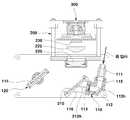
도 1은 본 발명의 일실시예에 따른 3차원 스캐닝 시스템을 도시한 사시도이다.
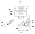
도 2는 본 발명의 일실시예에 따른 3차원 스캐닝 시스템을 도시한 단면도이다.
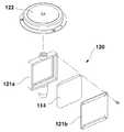
도 3은 본 발명의 일실시예에 따른 3차원 스캐닝 시스템의 광주사부를 도시한 분해사시도이다.
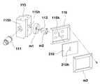
도 4는 본 발명의 일실시예에 따른 3차원 스캐닝 시스템을 도시한 일부 분해사시도이다.
도 5는 본 발명의 일실시예에 따른 3차원 스캐닝 시스템을 통해 광이 방출되는 경로를 표시한 도면이다.
도 6은 본 발명의 일실시예에 따른 3차원 스캐닝 시스템을 통해 광이 수신되는 경로를 표시한 도면이다.
도 7은 본 발명의 일실시예에 따른 3차원 스캐닝 시스템의 다른 실시예를 도시한 도면이다.
도 8은 DOE mask pattern(15mm X 15mm 사이즈) 구조를 예시한 도면이다.
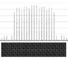
도 9 및 도 10은 회절광학소자에 의해 단점 입사광이 다점 입사광으로 분할되는 것을 예시한 도면이다.
도 11은 다점 도트 라인 광의 분포를 예시한 도면이다.1 is a perspective view illustrating a three-dimensional scanning system according to an embodiment of the present invention.
2 is a cross-sectional view illustrating a three-dimensional scanning system according to an exemplary embodiment of the present invention.
3 is an exploded perspective view illustrating an optical scanning unit of a three-dimensional scanning system according to an embodiment of the present invention.
4 is a partially exploded perspective view showing a three-dimensional scanning system according to an embodiment of the present invention.
FIG. 5 is a view illustrating a path through which light is emitted through a three-dimensional scanning system according to an embodiment of the present invention.
FIG. 6 is a diagram illustrating a path through which light is received through a three-dimensional scanning system according to an exemplary embodiment of the present invention. Referring to FIG.
7 is a view showing another embodiment of a three-dimensional scanning system according to an embodiment of the present invention.
Fig. 8 is a diagram illustrating a DOE mask pattern (15 mm x 15 mm size) structure.
Figs. 9 and 10 are views showing that a short point incident light is divided into multiple point incident light by the diffractive optical element.
11 is a diagram illustrating the distribution of the multi-point dot line light.
본 발명은 그 기술적 사상 또는 주요한 특징으로부터 벗어남이 없이 다른 여러가지 형태로 실시될 수 있다. 따라서, 본 발명의 실시예들은 모든 점에서 단순한 예시에 지나지 않으며 한정적으로 해석되어서는 안 된다.The present invention may be embodied in many other forms without departing from its spirit or essential characteristics. Accordingly, the embodiments of the present invention are to be considered in all respects as merely illustrative and not restrictive.
제1, 제2등의 용어는 다양한 구성요소들을 설명하는데 사용될 수 있지만, 상기 구성요소들은 상기 용어들에 의해 한정되어서는 안 된다.The terms first, second, etc. may be used to describe various components, but the components should not be limited by the terms.
상기 용어들은 하나의 구성요소를 다른 구성요소로부터 구별하는 목적으로만 사용된다. 예를 들어, 본 발명의 권리 범위를 벗어나지 않으면서 제1구성요소는 제2구성요소로 명명될 수 있고, 유사하게 제2구성요소도 제1구성요소로 명명될 수 있다.The terms are used only for the purpose of distinguishing one component from another. For example, without departing from the scope of the present invention, the first component may be referred to as a second component, and similarly, the second component may also be referred to as a first component.
및/또는 이라는 용어는 복수의 관련된 기재된 항목들의 조합 또는 복수의 관련된 기재된 항목들 중의 어느 항목을 포함한다.And / or < / RTI > includes any combination of a plurality of related listed items or any of a plurality of related listed items.
어떤 구성요소가 다른 구성요소에 "연결되어" 있다거나 "접속되어" 있다고 언급된 때에는, 그 다른 구성요소에 직접적으로 연결되어 있거나 또는 접속되어 있을 수도 있지만, 중간에 다른 구성요소가 존재할 수도 있다고 이해되어야 할 것이다.It is to be understood that when an element is referred to as being "connected" or "connected" to another element, it may be directly connected or connected to the other element, .
반면에, 어떤 구성요소가 다른 구성요소에 "직접 연결되어" 있다거나 "직접 접속되어" 있다고 언급된 때에는, 중간에 다른 구성요소가 존재하지 않는 것으로 이해되어야 할 것이다.On the other hand, when an element is referred to as being "directly connected" or "directly connected" to another element, it should be understood that there are no other elements in between.
본 출원에서 사용한 용어는 단지 특정한 실시예를 설명하기 위해 사용된 것으로, 본 발명을 한정하려는 의도가 아니다. 단수의 표현은 문맥상 명백하게 다르게 뜻하지 않는 한, 복수의 표현을 포함한다.The terminology used in this application is used only to describe a specific embodiment and is not intended to limit the invention. The singular expressions include plural expressions unless the context clearly dictates otherwise.
본 출원에서, "포함하다" 또는 "구비하다", "가지다" 등의 용어는 명세서상에 기재된 특징, 숫자, 단계, 동작, 구성요소, 부품 또는 이들을 조합한 것이 존재함을 지정하려는 것이지, 하나 또는 그 이상의 다른 특징들이나 숫자, 단계, 동작, 구성요소, 부품 또는 이들을 조합한 것들의 존재 또는 부가 가능성을 미리 배제하지 않는 것으로 이해되어야 한다.In the present application, the terms "comprises", "having", "having", and the like are intended to specify the presence of stated features, integers, steps, operations, components, Steps, operations, elements, components, or combinations of elements, numbers, steps, operations, components, parts, or combinations thereof.
다르게 정의되지 않는 한, 기술적이거나 과학적인 용어를 포함해서 여기서 사용되는 모든 용어들은 본 발명이 속하는 기술 분야에서 통상의 지식을 가진 자에 의해 일반적으로 이해되는 것과 동일한 의미를 가지고 있다.Unless defined otherwise, all terms used herein, including technical or scientific terms, have the same meaning as commonly understood by one of ordinary skill in the art to which this invention belongs.
일반적으로 사용되는 사전에 정의되어 있는 것과 같은 용어들은 관련 기술의 문맥상 가지는 의미와 일치하는 의미를 가지는 것으로 해석되어야 하며, 본 출원에서 명백하게 정의하지 않는 한, 이상적이거나 과도하게 형식적인 의미로 해석되지 않는다.Terms such as those defined in commonly used dictionaries are to be interpreted as having a meaning consistent with the contextual meaning of the related art and are to be interpreted as either ideal or overly formal in the sense of the present application Do not.
이하, 첨부된 도면을 참조하여 본 발명에 따른 바람직한 실시예를 상세히 설명하되, 도면 부호에 관계없이 동일하거나 대응하는 구성 요소는 동일한 참조 번호를 부여하고 이에 대한 중복되는 설명은 생략하기로 한다.Hereinafter, preferred embodiments of the present invention will be described in detail with reference to the accompanying drawings, wherein like or corresponding elements are denoted by the same reference numerals, and a duplicate description thereof will be omitted.
본 발명을 설명함에 있어서 관련된 공지 기술에 대한 구체적인 설명이 본 발명의 요지를 흐릴 수 있다고 판단되는 경우 그 상세한 설명을 생략한다.DETAILED DESCRIPTION OF THE PREFERRED EMBODIMENTS Hereinafter, the present invention will be described in detail with reference to the accompanying drawings.
본 발명의 일실시예에 따른 3차원 스캐닝 시스템은, 펄스 레이저 광을 소정의 시야각 범위를 커버하도록 회전시켜 주사하여 방출한 후 목표물로부터 반사된 반사광을 수신하여 목표물의 거리를 산출하여 3차원 영상을 획득하는 시스템으로서, 도 1 및 도 2에 도시된 바와 같이, 광송신모듈(100), 광수신모듈(200) 및 제어기(300)를 포함하여 구성된다.The three-dimensional scanning system according to an embodiment of the present invention rotates the pulsed laser light to cover a predetermined viewing angle range, and scans and emits the reflected pulsed laser light. Then, the reflected light reflected from the target is received to calculate the distance of the target, 1 and 2, the
본 실시예의 3차원 스캐닝 시스템은 전방 또는 측방의 장애물 등에 의한 위험 상황이 발생할 경우 운전자에게 경고하거나 자동차의 속도를 조절하는 조치를 자동적으로 수행할 수 있게 하는 운전 보조용 애플리케이션이나, 운전자 없이 운행하는 트랙터와 같은 자동 운전장치 등 다양한 분야에 적용될 수 있다.The three-dimensional scanning system of the present embodiment is a driving assistant application that can alert the driver or automatically take measures to adjust the speed of the vehicle when a dangerous situation occurs due to an obstacle on the front or side, And the like.
먼저, 상기 광송신모듈(100)에 대하여 설명하도록 한다.First, the
상기 광송신모듈(100)은 3차원 스캐닝을 위한 펄스 레이저 광을 방출하는 부분으로서, 도 2에 도시된 바와 같이, 광분할부(110)와 광주사부(120)를 포함하여 구성된다.The
상기 광분할부(110)는 광원(미도시)으로부터 제공되는 단점 입사광(L1, 펄스 레이저 광)을 분할하는 부분으로서, 예를 들어, 레이저 다이오드 등과 같은 광원으로부터 제공되는 단점 입사광(L1)의 광축을 정렬한 후 다점 출력광(L2)으로 분할하도록 구성될 수 있다.The
구체적으로, 상기 광분할부(110)는, 광원으로부터 제공되는 단점 입사광(L1)의 광축을 정렬시키는 콜리메이터(111), 상기 콜리메이터(111)에 의해 광축이 정렬된 단점 입사광(L1)의 경로를 전환시키는 입사광 반사부재(112), 상기 입사광 반사부재(112)에 의해 반사된 단점 입사광(L1)의 경로 상에 배치되어 상기 단점 입사광(L1)을 통과시킴에 따라 상기 단점 입사광(L1)을 다점 출력광(L2)으로 분할시키는 회절광학소자(113)를 포함하여 구성된다.Specifically, the
한편, 상기 콜리메이터(111), 입사광 반사부재(112), 회절광학소자(113)가 상기에서 설명한 바와 같은 관계로 배열될 수 있도록, 상기 광분할부(110)는 ㄱ자형으로 형성되어 내부에 ㄱ자형 통과홀(115h)이 형성된 광전환하우징(115), 일단이 상기 광전환하우징(115)의 일측단에 구비되고 타단에 경사부가 형성된 미러홀더(116)를 더 포함하여 구성될 수 있으며, 상기 회절광학소자(113)를 장착하기 위한 홀더하우징(m1, m2)와 반사광 반사부재(210)를 상기 미러홀더(116)의 경사부에 장착하기 위한 고정프레임(m3) 등이 더욱 구비될 수 있다.The
즉, 상기 광전환하우징(115)의 타측단에 구비된 콜리메이터(111)가 광원으로부터 제공되는 단점 입사광(L1)을 제공받아 광축을 정렬시킨 후 상기 입사광 반사부재(112)로 송신하고, 상기 광전환하우징(115)의 내부에 형성된 ㄱ자형 통과홀(115h)의 코너부에 구비된 상기 입사광 반사부재(112)가 단점 입사광(L1)을 대략 90°정도로 반사시켜 회절광학소자(113)를 향하여 송신하며, 상기 회절광학소자(113)는 상기 단점 입사광(L1)을 다점 출력광(L2)으로 분할하여 상기 미러홀더(116)에 형성된 슬릿형 홀(116h)을 통하여 광주사부(120)를 향하도록 송신하게 된다.That is, the
한편, 도 8에 도시된 바와 같이, 상기 회절광학소자(113)는 회절용 패턴이 형성되어 광의 회절이 이뤄지도록 하는 필터로서, 상기 콜리메이터(111)로부터 송신되는 단점 입사광(L1)을 소정 각도로 펼쳐진 도트 라인 형태의 다점 출력광(L2)으로 분할하게 된다.8, the diffraction
예를 들어, 상기 회절광학소자(113)는, Quartz 또는 Fused Silica Wafer 소재에 포토 리소그라피 제공정을 통해 회절광학소자(DOE, Diffractive Optical Element) 마스크 패턴을 식각함으로써 단점 입사광(L1)을 다점 출력광(L2)으로 분할하도록 구성될 수 있으며, 회절용 패턴을 다양하게 적용함에 따라, 도 9 및 도 10에 도시된 바와 같이, 상기 회절광학소자(113)로 입사된 단점 입사광(L1)이 8 도트 라인, 16 도트 라인, 32 도트 라인 등 다양한 수의 도트 라인의 다점 출력광(L2)이 되도록 함은 물론 단점 입사광(L1)에서 도트 라인으로 분할되는 퍼짐 각도를 수십 도까지 쉽게 조절할 수 있다.For example, the diffractive
상기 광주사부(120)는 상기 광분할부(110)에 의해 수직으로 분할된 도트 라인 형태의 다점 출력광(L2)을 소정의 시야각 범위를 커버하도록 회전시켜 주사하는 부분으로서, 상기 도트 라인 형태의 다점 출력광(L2)에 대해 수직인 방향으로 상기 도트 라인 형태의 다점 출력광(L2)을 소정의 시야각 범위(도 5의 α° 범위, 대략 60° 내지 90°)를 커버할 수 있도록 회전하면서 반사시키도록 구성되어, 적어도 상기 시야각(FOV, Field Of View)의 범위 구간에 대한 스캐닝이 이뤄질 수 있도록 한다.The
도 5에 도시된 바와 같이, 상기 광주사부(120)는 상기 회절광학소자(113)를 통과하여 도트 라인 형태로 분할된 다점 출력광(L2)의 진행 경로 상에 위치하도록 배치될 수 있으며, 상기 도트 라인 형태의 다점 출력광(L2)을 회전하면서 반사시킬 수 있도록 평면구조의 회전형 미러(114)를 포함하여 구성되며, 상기 회전형 미러(114)를 장착하기 위한 하우징(121a, 121b)과, 상기 하우징(121a, 121b)을 회전시킴에 따라 상기 회전형 미러(114)를 일방향으로 회전시키기 위한 구동모터(122)가 구비된다.As shown in FIG. 5, the
한편, 광 주사각도를 높이고, 리시버(230)의 수신광량을 높이며, 상기 도트 라인 형태의 다점 출력광(L2)을 보다 넓은 범위 각도로 반사시켜 주사할 수 있도록, 상기 평면구조의 회전형 미러(114)를 대체하여, 도 7에 도시된 바와 같이, 곡면구조의 회전형 미러(114)로 구성할 수도 있음은 물론이다.On the other hand, in order to increase the light scanning angle, increase the amount of light received by the
또한, 상기 회전형 미러(114)는 구동모터(122)의 회전축에 대해 양측면이 대칭으로 반사면을 형성하여 한 번의 회전으로 두 번 동일한 방향으로 광을 송수신할 수 있도록 구성함으로써 2배 빠른 속도로 3차원 영상을 획득할 수 있도록 제작할 수 있다.In addition, the
상술한 바와 같이, 광분할부(110)와 광주사부(120)로 구성된 광송신모듈(100)의 구성에 따르면, 광원으로부터 제공되는 단점 입사광(L1)의 광축을 정렬한 후 도트 라인 형태의 다점 출력광(L2)으로 수직 분할하여 회전하면서 반사시킴에 따라 일정한 각도로 스캐닝을 하는 목표물을 향한 방향에 대한 소정의 수평의 시야각 범위를 커버할 수 있는 형태로 주사할 수 있게 된다.As described above, according to the configuration of the
특히, 실선(Solid Line)이 아닌 도트 라인(Dot Line) 형태의 다점 출력광(L2)을 3차원 스캔을 위해 사용함으로써 저출력 광원을 이용하면서도 단위 스캐닝 픽셀 당 수신되는 광의 밀도를 높여 높은 수준의 반사광 신호를 얻을 수 있고, 이를 통해 광송신모듈(100)의 무게를 획기적으로 줄일 수 있음은 물론 구조를 간소화할 수 있게 된다.In particular, by using a multi-point output light (L2) in the form of a dot line (not a solid line) for three-dimensional scanning, the density of light received per unit scanning pixel is increased, Signal, thereby greatly reducing the weight of the
다음으로, 상기 광수신모듈(200) 및 제어기(300)에 대하여 설명하도록 한다.Next, the
상기 광수신모듈(200)은 상기 광송신모듈(100)에서 방출된 후 목표물로부터 반사된 반사광(L3)을 수신하기 위한 부분으로서, 반사광(L3)을 수신하여 상기 제어기(300) 측으로 송신되도록 하며, 반사광(L3)을 수신하기 위한 렌즈(220) 및 광검출소자(230, Photo Detector)등을 포함하여 구성될 수 있다.The
상기 광송신모듈(100)에서 방출된 후 목표물로부터 반사되어 상기 광수신모듈(200)로 수신되는 반사광(L3)은, 상기 회전형 미러(114)에 의해 반사되어 1차적으로 경로가 전환되고, 상기 회전형 미러(114)에 의해 반사된 반사광(L3)의 경로 상에 배치된 반사광 반사부재(210)에 의해 2차적으로 경로가 전환되어 상기 광수신모듈(200)의 렌즈(220) 및 실린더리컬렌즈(225)를 통과하여 광검출소자(230)로 수신될 수 있으며, 상기 반사광 반사부재(210)는 상기 미러홀더(116)의 경사부 상에 구비되어 반사광(L3)이 광수신모듈(200)로 수신될 수 있도록 반사하게 된다.The reflected light L3 reflected from the target after being emitted from the
상기 렌즈(220)는 비구면렌즈(Aspheric Lens)이고, 상기 실린더리컬렌즈(225)는 렌즈 표면이 원주의 측면 형태로 형성된 렌즈로서, 예를 들어, 상기 회전형 미러(114)에 의해 상기 광검출소자(230)로 수신되는 반사광(L3)을 직선라인 형태로 집광하여 상기 광검출소자(230)의 광검출 영역으로 반사광(L3)이 모일 수 있도록 한다.The
한편, 상기 반사광 반사부재(210)의 중앙측에는, 상기 회절광학소자(113)에 의해 분할된 도트 라인 형태의 다점 출력광(L2)을 통과시키기 위한 슬릿 형태의 통과홀(210h)이 형성될 수 있다.On the other hand, a slit-shaped through-
그리고, 상기 반사광 반사부재(210)의 표면은 상기 슬릿형태의 통과홀(210h)과 같은 방향으로 곡률을 가지는 곡면의 형태로 형성될 수 있으며, 이러한 형상을 통해 작은 크기의 통과홀(210h)을 형성하면서도 광검출소자(230)로 수신되는 광량을 극대화할 수 있게 된다.The surface of the reflection
상술한 바와 같은 광수신모듈(200)의 구성에 따르면, 회전형 미러(114)와 반사광 반사부재(210)에 의해 경로가 전환된 반사광(L3)을 수신하게 되며, 수신된 반사광(L3)에 대한 정보를 제어기(300)로 전송하게 되고, 상기 제어기(300)는 상기 광수신모듈(200)로 수신된 반사광(L3)에 근거하여 목표물의 화상을 생성하게 된다.According to the configuration of the
한편, 상기 회절광학소자(113)에 의해 분할된 도트 라인 형태의 다점 출력광(L2)은, 도 11에 도시된 바와 같이, 양 단부 측을 향할수록 광량이 적을 수 있는데, 이를 보완하기 위한 수광렌즈(220)나 광검출소자(230)의 출력신호를 차등 증폭회로를 적용하여 보완할 수 있다. 도 11의 세로축은 광량, 가로축은 수직 도트 라인의 상태위치를 의미한다.On the other hand, as shown in FIG. 11, the dot-shaped multi-point output light L2 divided by the diffractive
상술한 바와 같이, 광송신모듈(100), 광수신모듈(200) 및 제어기(300)를 포함하는 3차원 레이저 스캐닝 시스템의 구성에 따르면, 회절광학소자(113)를 이용하여 단점 입사광(L1)을 실선(Solid Line)이 아닌 도트 라인(Dot Line) 형태의 다점 출력광(L2)을 분할하여 방출하는 방식으로 3차원 스캔이 이뤄지도록 구성됨에 따라 저출력의 레이저 광파워를 이용하면서도 단위 스캐닝 픽셀 당 수신되는 광의 밀도를 높여 높은 수준의 거리영상신호를 얻을 수 있으며, 또한, 회절광학소자(113)의 회절용 패턴을 변경하는 방식으로 다점 출력광(L2)의 갯수와 퍼짐 각도를 간단하게 조절할 수 있어 정밀도 요구에 맞도록 쉽게 변경할 수 있는 이점이 있다.As described above, according to the configuration of the three-dimensional laser scanning system including the
본 발명은 첨부된 도면을 참조하여 바람직한 실시예를 중심으로 기술되었지만 당업자라면 이러한 기재로부터 본 발명의 범주를 벗어남이 없이 많은 다양하고 자명한 변형이 가능하다는 것은 명백하다. 따라서 본 발명의 범주는 이러한 많은 변형예들을 포함하도록 기술된 특허청구범위에 의해서 해석돼야 한다.Although the present invention has been described with reference to the preferred embodiments thereof with reference to the accompanying drawings, it will be apparent to those skilled in the art that many other obvious modifications can be made therein without departing from the scope of the invention. Accordingly, the scope of the present invention should be interpreted by the appended claims to cover many such variations.
100:광송신모듈110:광분할부
111:콜리메이터112:입사광 반사부재
113:회절광학소자114:회전형미러
115:광전환하우징115h:ㄱ자형 통과홀
116:미러홀더120:광주사부
121a, 121b:하우징122:구동모터
200:광수신모듈210:반사광 반사부재
210h:통과홀300:제어기
L1:단점 입사광L2:다점 출력광
L3:반사광100: optical transmission module 110:
111: collimator 112: incident light reflection member
113: diffractive optical element 114: rotatable mirror
115:
116: mirror holder 120:
121a, 121b: housing 122: drive motor
200: light receiving module 210:
210h: through hole 300: controller
L1: Negative point incident light L2: Multi point output light
L3: Reflected light
Claims (10)
Translated fromKorean상기 광송신모듈에서 방출된 후 목표물로부터 반사된 반사광을 수신하기 위한 광수신모듈; 및
상기 광수신모듈로 수신된 반사광에 근거하여 목표물의 화상을 생성하는 제어기;를 포함하여 구성되고,
상기 광분할부는,
광원으로부터 제공된 단점 입사광의 광축을 정렬시키는 콜리메이터;
상기 콜리메이터에 의해 광축이 정렬된 단점 입사광의 경로를 전환시키는 입사광 반사부재; 및
상기 입사광 반사부재에 의해 반사된 단점 입사광의 경로 상에 배치되어 상기 단점 입사광을 통과시킴에 따라 상기 단점 입사광을 도트 라인 형태의 다점 출력광으로 분할시키는 회절광학소자;를 포함하여 구성되고,
상기 광주사부는,
상기 회절광학소자에 의해 분할된 도트 라인 형태의 다점 출력광의 경로 상에 배치되어 상기 도트 라인 형태의 다점 출력광에 대해 수직인 방향으로 상기 도트 라인 형태의 다점 출력광을 회전하면서 반사시켜 소정의 시야각 범위를 커버하도록 하는 회전형 미러;를 포함하여 구성되되, 상기 회전형 미러는 양측 표면에 평면 미러가 구비되거나, 양측 표면에 회전 방향으로 굴곡진 곡면 미러가 구비되고, 일방향 회전 구동모터에 의해 일방향으로 회전하도록 구성됨에 따라 한 번 회전 시 동일방향의 광을 두 번 송수신할 수 있도록 구성되며,
상기 광송신모듈에서 방출된 후 목표물로부터 반사되어 상기 광수신모듈로 수신되는 반사광은,
상기 회전형 미러에 의해 반사되어 1차적으로 경로가 전환되고, 상기 회전형 미러에 의해 반사된 반사광의 경로 상에 배치된 반사광 반사부재에 의해 2차적으로 경로가 전환되어 상기 광수신모듈로 수신되는 것을 특징으로 하는 3차원 스캐닝 시스템.An optical transmission module including a light splitting part for splitting the short point incident light into the multi point output light and an optical scanning part for rotating and scanning the multi point output light divided by the light splitting part to cover a predetermined viewing angle range;
A light receiving module for receiving the reflected light reflected from the target after being emitted from the optical transmitting module; And
And a controller for generating an image of a target based on the reflected light received by the light receiving module,
The light-
A collimator for aligning the optical axis of the short point incident light provided from the light source;
An incident light reflecting member for changing the path of the short point incident light whose optical axis is aligned by the collimator; And
And a diffractive optical element disposed on the path of the short point incident light reflected by the incident light reflecting member and dividing the short point incident light into the dot point type output light as passing the short point incident light,
The optical scanning unit includes:
Point output light in the form of a dot line in the direction perpendicular to the multi-point output light in the form of a dot line, while being reflected on the path of the multi-point output light in the form of a dot line divided by the diffractive optical element, Wherein the rotating mirror is provided with a flat mirror on both side surfaces thereof or a curved mirror that is curved in the rotating direction on both side surfaces thereof and is provided with a one- So that light in the same direction can be transmitted and received twice when rotated once,
The reflected light reflected from the target and received by the light receiving module after being emitted from the optical transmitting module,
A path is firstly reflected by the rotatable mirror, a path is secondarily switched by a reflected light reflecting member disposed on the path of the reflected light reflected by the rotatable mirror, and is received by the optical receiver module Dimensional scanning system.
상기 광분할부는,
상기 단점 입사광을 소정 각도로 펼쳐진 도트 라인 형태의 다점 출력광으로 분할하도록 구성된 것을 특징으로 하는 3차원 스캐닝 시스템.The method according to claim 1,
The light-
And divides the short-point incident light into a multi-point output light in the form of a dot line extending at a predetermined angle.
상기 광주사부는,
상기 도트 라인 형태의 다점 출력광에 대해 수직인 방향으로 상기 도트 라인 형태의 다점 출력광을 소정의 시야각 범위를 커버하도록 회전하면서 반사시키도록 구성된 것을 특징으로 하는 3차원 스캐닝 시스템.3. The method of claim 2,
The optical scanning unit includes:
Wherein the multi-point output light of the dot line shape is rotated and reflected so as to cover a predetermined viewing angle range in a direction perpendicular to the multi-point output light of the dot line type.
상기 광분할부는,
회절용 패턴이 형성된 회절광학소자를 통해 상기 단점 입사광을 다점 출력광으로 분할하도록 구성된 것을 특징으로 하는 3차원 스캐닝 시스템.The method according to claim 1,
The light-
Wherein the diffractive optical element is configured to divide the short-point incident light into the multi-point output light through the diffractive optical element in which the diffraction pattern is formed.
상기 반사광 반사부재의 중앙측에는,
상기 회절광학소자에 의해 분할된 도트 라인 형태의 다점 출력광을 통과시키기 위한 통과홀이 형성된 것을 특징으로 하는 3차원 스캐닝 시스템.The method according to claim 1,
On the center side of the reflected light reflecting member,
And a through hole for passing the multi-point output light in the form of a dot line divided by the diffractive optical element is formed.
상기 광분할부는,
ㄱ자형으로 형성되어 내부에 ㄱ자형 통과홀이 형성된 광전환하우징;
일단이 상기 광전환하우징의 일측단에 구비되고, 타단에 경사부가 형성된 미러홀더;를 더 포함하여 구성되며,
상기 콜리메이터는 상기 광전환하우징의 타측단에 구비되고, 상기 입사광 반사부재는 상기 광전환하우징의 내부에 형성된 ㄱ자형 통과홀의 코너부에 구비되며, 상기 반사광 반사부재는 상기 미러홀더의 경사부 상에 구비되는 것을 특징으로 하는 3차원 스캐닝 시스템.The method according to claim 1,
The light-
A light switching housing formed in a square shape and having a through hole formed therein;
And a mirror holder having one end provided at one end of the light switching housing and the other end formed with an inclined portion,
The collimator is provided at the other end of the light switching housing, and the incident light reflecting member is provided at a corner of the through hole formed in the light switching housing, and the reflected light reflecting member is disposed on the inclined portion of the mirror holder Dimensional scanning system.
Priority Applications (2)
| Application Number | Priority Date | Filing Date | Title |
|---|---|---|---|
| KR1020150170694AKR101884781B1 (en) | 2015-12-02 | 2015-12-02 | Three dimensional scanning system |
| PCT/KR2016/012015WO2017073982A1 (en) | 2015-10-30 | 2016-10-25 | Three-dimensional scanning system |
Applications Claiming Priority (1)
| Application Number | Priority Date | Filing Date | Title |
|---|---|---|---|
| KR1020150170694AKR101884781B1 (en) | 2015-12-02 | 2015-12-02 | Three dimensional scanning system |
Publications (2)
| Publication Number | Publication Date |
|---|---|
| KR20170065061A KR20170065061A (en) | 2017-06-13 |
| KR101884781B1true KR101884781B1 (en) | 2018-08-03 |
Family
ID=59218590
Family Applications (1)
| Application Number | Title | Priority Date | Filing Date |
|---|---|---|---|
| KR1020150170694AActiveKR101884781B1 (en) | 2015-10-30 | 2015-12-02 | Three dimensional scanning system |
Country Status (1)
| Country | Link |
|---|---|
| KR (1) | KR101884781B1 (en) |
Cited By (3)
| Publication number | Priority date | Publication date | Assignee | Title |
|---|---|---|---|---|
| KR20210004761A (en)* | 2019-07-05 | 2021-01-13 | 주식회사 라이드로 | Lidar optical apparatus and lidar apparatus having same |
| EP3951422A4 (en)* | 2019-03-25 | 2022-12-21 | Suteng Innovation Technology Co., Ltd. | Laser radar, and installation and adjustment method therefor |
| US11782144B2 (en) | 2019-04-04 | 2023-10-10 | Suteng Innovation Technology Co., Ltd. | Lidar and adjustment method thereof |
Families Citing this family (4)
| Publication number | Priority date | Publication date | Assignee | Title |
|---|---|---|---|---|
| CN109387160A (en)* | 2018-11-26 | 2019-02-26 | 中国科学院光电技术研究所 | Object surface contour measuring device and method in nuclear radiation environment |
| CN112198669B (en)* | 2019-07-08 | 2022-07-26 | 三赢科技(深圳)有限公司 | Structured light projection module, depth camera and electronic device |
| CN110501689B (en)* | 2019-09-24 | 2024-06-18 | 中国工程物理研究院电子工程研究所 | Underwater laser circumferential scanning beam emission system |
| KR102656294B1 (en)* | 2020-06-23 | 2024-04-19 | 주식회사 라이드로 | Lidar apparatus |
Citations (3)
| Publication number | Priority date | Publication date | Assignee | Title |
|---|---|---|---|---|
| JP2000161961A (en)* | 1993-01-16 | 2000-06-16 | Topcon Corp | Rotary laser device |
| JP2006500598A (en)* | 2002-09-25 | 2006-01-05 | イベオ アオトモビーレ ゼンゾア ゲーエムベーハー | Photoelectric detection device |
| KR101357051B1 (en)* | 2012-05-22 | 2014-02-04 | 한국생산기술연구원 | Three dimensional scanning system and three dimensional image acqusition method using the same |
Family Cites Families (4)
| Publication number | Priority date | Publication date | Assignee | Title |
|---|---|---|---|---|
| US7365834B2 (en)* | 2003-06-24 | 2008-04-29 | Kla-Tencor Technologies Corporation | Optical system for detecting anomalies and/or features of surfaces |
| KR101391298B1 (en)* | 2012-08-21 | 2014-05-07 | 한국생산기술연구원 | Three dimensional laser scanning system |
| EP2743724B1 (en)* | 2012-12-12 | 2015-09-23 | Espros Photonics AG | TOF distance sensor and method for operating the same |
| KR101545971B1 (en)* | 2013-12-11 | 2015-08-24 | 한국생산기술연구원 | System for sensing complex image |
- 2015
- 2015-12-02KRKR1020150170694Apatent/KR101884781B1/enactiveActive
Patent Citations (3)
| Publication number | Priority date | Publication date | Assignee | Title |
|---|---|---|---|---|
| JP2000161961A (en)* | 1993-01-16 | 2000-06-16 | Topcon Corp | Rotary laser device |
| JP2006500598A (en)* | 2002-09-25 | 2006-01-05 | イベオ アオトモビーレ ゼンゾア ゲーエムベーハー | Photoelectric detection device |
| KR101357051B1 (en)* | 2012-05-22 | 2014-02-04 | 한국생산기술연구원 | Three dimensional scanning system and three dimensional image acqusition method using the same |
Cited By (5)
| Publication number | Priority date | Publication date | Assignee | Title |
|---|---|---|---|---|
| EP3951422A4 (en)* | 2019-03-25 | 2022-12-21 | Suteng Innovation Technology Co., Ltd. | Laser radar, and installation and adjustment method therefor |
| US11782144B2 (en) | 2019-04-04 | 2023-10-10 | Suteng Innovation Technology Co., Ltd. | Lidar and adjustment method thereof |
| US12326527B2 (en) | 2019-04-04 | 2025-06-10 | Suteng Innovation Technology Co., Ltd. | Lidar and adjustment method thereof |
| KR20210004761A (en)* | 2019-07-05 | 2021-01-13 | 주식회사 라이드로 | Lidar optical apparatus and lidar apparatus having same |
| KR102474126B1 (en)* | 2019-07-05 | 2022-12-05 | 주식회사 라이드로 | Lidar optical apparatus and lidar apparatus having same |
Also Published As
| Publication number | Publication date |
|---|---|
| KR20170065061A (en) | 2017-06-13 |
Similar Documents
| Publication | Publication Date | Title |
|---|---|---|
| KR101884781B1 (en) | Three dimensional scanning system | |
| CN108226899B (en) | Laser radar and working method thereof | |
| CN103038664B (en) | active illumination scanning imager | |
| US10481266B2 (en) | Multi-range three-dimensional imaging systems | |
| US10859677B2 (en) | Laser scanner for motor vehicles | |
| US10996322B2 (en) | Lidar sensor | |
| KR102038533B1 (en) | Laser Radar System and Method for Acquiring Target Image | |
| KR102020037B1 (en) | Hybrid LiDAR scanner | |
| US11561287B2 (en) | LIDAR sensors and methods for the same | |
| US10788574B2 (en) | LIDAR device and LIDAR system including the same | |
| KR102210101B1 (en) | Optical structure and scanning LiDAR having the same | |
| KR102209500B1 (en) | Lidar apparatus | |
| KR102059258B1 (en) | LiDAR scanning device | |
| KR20180058068A (en) | Mirror rotational optical structure for 360˚ multichannel scanning and 3d lidar system comprising the same | |
| US11579259B2 (en) | Laser scanner, for example for a LIDAR system of a driver assistance system | |
| US11561284B2 (en) | Parallax compensating spatial filters | |
| KR101867967B1 (en) | Polyhedron optical structure for 360˚ laser scanning and 3d lidar system comprising the same | |
| US11879996B2 (en) | LIDAR sensors and methods for LIDAR sensors | |
| KR20170134945A (en) | Lidar optical apparatus including improved structure | |
| US20200150418A1 (en) | Distance measurement device and mobile body | |
| KR102013165B1 (en) | Rotational scanning LiDAR | |
| KR102438071B1 (en) | Lidar scanning device capable of front and rear measurement | |
| KR102511118B1 (en) | Lidar optical apparatus | |
| KR101744610B1 (en) | Three dimensional scanning system | |
| CN221465737U (en) | Laser radar |
Legal Events
| Date | Code | Title | Description |
|---|---|---|---|
| A201 | Request for examination | ||
| PA0109 | Patent application | Patent event code:PA01091R01D Comment text:Patent Application Patent event date:20151202 | |
| PA0201 | Request for examination | ||
| PG1501 | Laying open of application | ||
| E902 | Notification of reason for refusal | ||
| PE0902 | Notice of grounds for rejection | Comment text:Notification of reason for refusal Patent event date:20170828 Patent event code:PE09021S01D | |
| E902 | Notification of reason for refusal | ||
| PE0902 | Notice of grounds for rejection | Comment text:Notification of reason for refusal Patent event date:20180302 Patent event code:PE09021S01D | |
| E701 | Decision to grant or registration of patent right | ||
| PE0701 | Decision of registration | Patent event code:PE07011S01D Comment text:Decision to Grant Registration Patent event date:20180726 | |
| PR0701 | Registration of establishment | Comment text:Registration of Establishment Patent event date:20180727 Patent event code:PR07011E01D | |
| PR1002 | Payment of registration fee | Payment date:20180730 End annual number:3 Start annual number:1 | |
| PG1601 | Publication of registration | ||
| PR1001 | Payment of annual fee | Payment date:20210701 Start annual number:4 End annual number:4 | |
| PR1001 | Payment of annual fee | Payment date:20220623 Start annual number:5 End annual number:5 | |
| PR1001 | Payment of annual fee | Payment date:20230626 Start annual number:6 End annual number:6 | |
| PR1001 | Payment of annual fee | Payment date:20240624 Start annual number:7 End annual number:7 | |
| PR1001 | Payment of annual fee | Payment date:20250623 Start annual number:8 End annual number:8 |