KR101883069B1 - Optical Imaging System - Google Patents
Optical Imaging SystemDownload PDFInfo
- Publication number
- KR101883069B1 KR101883069B1KR1020160136720AKR20160136720AKR101883069B1KR 101883069 B1KR101883069 B1KR 101883069B1KR 1020160136720 AKR1020160136720 AKR 1020160136720AKR 20160136720 AKR20160136720 AKR 20160136720AKR 101883069 B1KR101883069 B1KR 101883069B1
- Authority
- KR
- South Korea
- Prior art keywords
- lens
- optical system
- imaging optical
- conditional expression
- refractive power
- Prior art date
- Legal status (The legal status is an assumption and is not a legal conclusion. Google has not performed a legal analysis and makes no representation as to the accuracy of the status listed.)
- Active
Links
Images


Classifications
- G—PHYSICS
- G02—OPTICS
- G02B—OPTICAL ELEMENTS, SYSTEMS OR APPARATUS
- G02B13/00—Optical objectives specially designed for the purposes specified below
- G02B13/001—Miniaturised objectives for electronic devices, e.g. portable telephones, webcams, PDAs, small digital cameras
- G02B13/0015—Miniaturised objectives for electronic devices, e.g. portable telephones, webcams, PDAs, small digital cameras characterised by the lens design
- G02B13/002—Miniaturised objectives for electronic devices, e.g. portable telephones, webcams, PDAs, small digital cameras characterised by the lens design having at least one aspherical surface
- G02B13/0045—Miniaturised objectives for electronic devices, e.g. portable telephones, webcams, PDAs, small digital cameras characterised by the lens design having at least one aspherical surface having five or more lenses
- G—PHYSICS
- G02—OPTICS
- G02B—OPTICAL ELEMENTS, SYSTEMS OR APPARATUS
- G02B23/00—Telescopes, e.g. binoculars; Periscopes; Instruments for viewing the inside of hollow bodies; Viewfinders; Optical aiming or sighting devices
- G02B23/24—Instruments or systems for viewing the inside of hollow bodies, e.g. fibrescopes
- G02B23/2476—Non-optical details, e.g. housings, mountings, supports
- G02B23/2484—Arrangements in relation to a camera or imaging device
- G—PHYSICS
- G02—OPTICS
- G02B—OPTICAL ELEMENTS, SYSTEMS OR APPARATUS
- G02B1/00—Optical elements characterised by the material of which they are made; Optical coatings for optical elements
- G02B1/04—Optical elements characterised by the material of which they are made; Optical coatings for optical elements made of organic materials, e.g. plastics
- G—PHYSICS
- G02—OPTICS
- G02B—OPTICAL ELEMENTS, SYSTEMS OR APPARATUS
- G02B13/00—Optical objectives specially designed for the purposes specified below
- G02B13/18—Optical objectives specially designed for the purposes specified below with lenses having one or more non-spherical faces, e.g. for reducing geometrical aberration
- G—PHYSICS
- G02—OPTICS
- G02B—OPTICAL ELEMENTS, SYSTEMS OR APPARATUS
- G02B3/00—Simple or compound lenses
- G02B3/02—Simple or compound lenses with non-spherical faces
- G—PHYSICS
- G02—OPTICS
- G02B—OPTICAL ELEMENTS, SYSTEMS OR APPARATUS
- G02B9/00—Optical objectives characterised both by the number of the components and their arrangements according to their sign, i.e. + or -
- G02B9/62—Optical objectives characterised both by the number of the components and their arrangements according to their sign, i.e. + or - having six components only
Landscapes
- Physics & Mathematics (AREA)
- General Physics & Mathematics (AREA)
- Optics & Photonics (AREA)
- Lenses (AREA)
- Engineering & Computer Science (AREA)
- Multimedia (AREA)
- Astronomy & Astrophysics (AREA)
Abstract
Translated fromKoreanDescription
Translated fromKorean본 발명은 6매 렌즈로 구성된 망원용 촬상 광학계에 관한 것이다.The present invention relates to a telephoto imaging optical system composed of a six-lens system.
원거리 촬영이 가능한 망원용 광학계는 상당한 크기를 갖는다. 예를 들어, 망원용 광학계는 광학계 전체 길이(TL)에 대한 전체 초점거리(f)의 비(TL/f)가 1 이상이다. 때문에, 망원용 광학계는 휴대 단말기 등과 같은 소형 전자제품에는 탑재하기 어렵다.The telescopic optical system capable of long-distance photographing has a considerable size. For example, the telephoto optical system has a ratio (TL / f) of the total focal length f to the total length (TL) of the optical system of 1 or more. Therefore, it is difficult to mount the telephoto optical system on small electronic products such as portable terminals.
본 발명은 원거리 촬영이 가능하면서도 소형 단말기에 탑재될 수 있는 촬상 광학계를 제공하는데 그 목적이 있다.An object of the present invention is to provide an imaging optical system that can be mounted on a small terminal while being capable of long-distance imaging.
상기 목적을 달성하기 위한 촬상 광학계는 정의 굴절력을 갖는 제1렌즈; 부의 굴절력을 갖는 제2렌즈; 부의 굴절력을 갖는 제3렌즈; 굴절력을 갖는 제4렌즈; 부의 굴절력을 갖는 제5렌즈; 및 정의 굴절력을 가지며, 상 측면이 볼록한 형상인 제6렌즈;를 포함한다.An imaging optical system for achieving the above object comprises: a first lens having a positive refractive power; A second lens having a negative refractive power; A third lens having a negative refractive power; A fourth lens having a refractive power; A fifth lens having a negative refractive power; And a sixth lens having a positive refractive power and having a convex shape on an upper side.
본 발명은 원거리 촬영이 가능하면서도 소형 단말기에 팁재될 수 있는 촬상 광학계를 구현할 수 있다.The present invention can realize an imaging optical system that can be used as a tip in a small terminal while being capable of long-distance photographing.
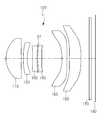
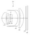
도 1은 본 발명의 제1실시 예에 따른 촬상 광학계의 구성도
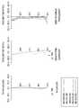
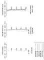
도 2는 도 1에 도시된 촬상 광학계의 수차 곡선을 나타낸 그래프
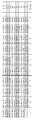
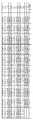
도 3은 도 1에 도시된 촬상 광학계의 비구면 특성을 나타낸 표
도 4는 본 발명의 제2실시 예에 따른 촬상 광학계의 구성도
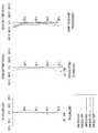
도 5는 도 4에 도시된 촬상 광학계의 수차 곡선을 나타낸 그래프
도 6은 도 5에 도시된 촬상 광학계의 비구면 특성을 나타낸 표
도 7은 본 발명의 제3실시 예에 따른 촬상 광학계의 구성도
도 8은 도 7에 도시된 촬상 광학계의 수차 곡선을 나타낸 그래프
도 9는 도 7에 도시된 촬상 광학계의 비구면 특성을 나타낸 표
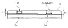
도 10은 본 발명의 일 실시 예에 따른 촬상 광학계가 탑재된 휴대 단말기의 배면도
도 11은 도 10에 도시된 휴대 단말기의 단면도1 is a configuration diagram of an imaging optical system according to a first embodiment of the present invention
Fig. 2 is a graph showing aberration curves of the imaging optical system shown in Fig. 1
3 is a table showing aspheric characteristics of the imaging optical system shown in Fig.
4 is a configuration diagram of an imaging optical system according to a second embodiment of the present invention
Fig. 5 is a graph showing aberration curves of the imaging optical system shown in Fig. 4
6 is a table showing aspheric characteristics of the imaging optical system shown in Fig. 5
7 is a configuration diagram of an imaging optical system according to the third embodiment of the present invention
8 is a graph showing aberration curves of the imaging optical system shown in Fig. 7
9 is a table showing aspheric characteristics of the imaging optical system shown in Fig. 7
10 is a rear view of a portable terminal equipped with an imaging optical system according to an embodiment of the present invention
11 is a sectional view of the portable terminal shown in Fig. 10
이하, 본 발명의 바람직한 실시 예를 첨부된 예시도면에 의거하여 상세히 설명한다.DETAILED DESCRIPTION OF THE PREFERRED EMBODIMENTS Hereinafter, preferred embodiments of the present invention will be described in detail with reference to the accompanying drawings.
아래에서 본 발명을 설명함에 있어서, 본 발명의 구성요소를 지칭하는 용어들은 각각의 구성요소들의 기능을 고려하여 명명된 것이므로, 본 발명의 기술적 구성요소를 한정하는 의미로 이해되어서는 안 될 것이다.In describing the present invention, it is to be understood that the terminology used herein is for the purpose of describing the present invention only and is not intended to limit the technical scope of the present invention.
아울러, 명세서 전체에서, 어떤 구성이 다른 구성과 '연결'되어 있다 함은 이들 구성들이 '직접적으로 연결'되어 있는 경우뿐만 아니라, 다른 구성을 사이에 두고 '간접적으로 연결'되어 있는 경우도 포함하는 것을 의미한다. 또한, 어떤 구성요소를 '포함'한다는 것은, 특별히 반대되는 기재가 없는 한 다른 구성요소를 제외하는 것이 아니라 다른 구성요소를 더 포함할 수 있다는 것을 의미한다.In addition, throughout the specification, a configuration is referred to as being 'connected' to another configuration, including not only when the configurations are directly connected but also when they are indirectly connected with each other . Also, to "include" an element means that it may include other elements, rather than excluding other elements, unless specifically stated otherwise.
아울러, 본 명세서에서 제1렌즈는 물체(또는 피사체)와 가장 가까운 렌즈를 의미하고, 제6렌즈는 상면(또는 이미지 센서)과 가장 가까운 렌즈를 의미한다. 본 명세서에서 렌즈의 곡률 반지름(Radius), 두께(Thickness), TL, IMG HT(상면의 대각길이의 1/2), 초점거리의 단위는 모두 ㎜ 단위이다. 아울러, 렌즈의 두께, 렌즈 간의 간격, TL은 렌즈의 광축에서의 거리이다. 아울러, 렌즈의 형상에 대한 설명에서 일면이 볼록한 형상이라는 의미는 해당 면의 광축 부분이 볼록하다는 의미이고, 일면이 오목한 형상이라는 의미는 해당 면의 광축 부분이 오목하다는 의미이다. 따라서, 렌즈의 일면이 볼록한 형상이라고 설명되어도, 렌즈의 가장자리 부분은 오목할 수 있다. 마찬가지로, 렌즈의 일면이 오목한 형상이라고 설명되어도, 렌즈의 가장자리 부분은 볼록할 수 있다.
Further, in this specification, the first lens means the lens closest to the object (or the subject), and the sixth lens means the lens closest to the image surface (or image sensor). In this specification, the curvature radius (Radius), the thickness, the TL, the IMG HT (1/2 of the diagonal length of the upper surface) of the lens, and the unit of the focal length are all in mm. The thickness of the lens, the distance between the lenses, and TL are distances from the optical axis of the lens. In addition, in the description of the shape of the lens, the convex shape of one surface means that the optical axis portion of the surface is convex, and the concave shape of one surface means that the optical axis portion of the surface is concave. Therefore, even if one surface of the lens is described as a convex shape, the edge portion of the lens can be concave. Similarly, even if one surface of the lens is described as a concave shape, the edge portion of the lens can be convex.
촬상 광학계는 6매의 렌즈를 포함한다. 예를 들어, 촬상 광학계는 물체 측으로부터 순차적으로 배치되는 제1렌즈, 제2렌즈, 제3렌즈, 제4렌즈, 제5렌즈, 제6렌즈를 포함할 수 있다.The imaging optical system includes six lenses. For example, the imaging optical system may include a first lens, a second lens, a third lens, a fourth lens, a fifth lens, and a sixth lens sequentially arranged from the object side.
제1렌즈는 굴절력을 가진다. 예를 들어, 제1렌즈는 정의 굴절력을 가진다. 제1렌즈는 적어도 일면이 볼록한 형상이다. 예를 들어, 제1렌즈는 물체 측면이 볼록한 형상이다.The first lens has a refractive power. For example, the first lens has a positive refractive power. The first lens has at least one convex shape. For example, the first lens has a convex shape on the side of the object.
제1렌즈는 비구면을 포함한다. 예를 들어, 제1렌즈는 양면이 모두 비구면일 수 있다. 제1렌즈는 광 투과율이 높고 가공성이 우수한 재질로 제작될 수 있다. 예를 들어, 제1렌즈는 플라스틱 재질로 제작될 수 있다. 그러나 제1렌즈의 재질이 플라스틱 재질로 한정되는 것은 아니다. 예를 들어, 제1렌즈는 유리 재질로 제작될 수 있다. 제1렌즈는 낮은 굴절률을 갖는다. 예를 들어, 제1렌즈의 굴절률은 1.6 미만일 수 있다.The first lens includes an aspherical surface. For example, the first lens may be both aspherical on both sides. The first lens can be made of a material having high light transmittance and excellent workability. For example, the first lens may be made of a plastic material. However, the material of the first lens is not limited to a plastic material. For example, the first lens may be made of glass. The first lens has a low refractive index. For example, the refractive index of the first lens may be less than 1.6.
제2렌즈는 굴절력을 가진다. 예를 들어, 제2렌즈는 부의 굴절력을 가진다. 제2렌즈는 일면이 볼록한 형상이다. 예를 들어, 제2렌즈는 물체 측면이 볼록한 형상일 수 있다.The second lens has a refractive power. For example, the second lens has a negative refractive power. The second lens has a convex shape on one side. For example, the second lens may have a convex shape on the object side.
제2렌즈는 비구면을 포함한다. 예를 들어, 제2렌즈는 물체 측면이 비구면일 수 있다. 제2렌즈는 광 투과율이 높고 가공성이 우수한 재질로 제작될 수 있다. 예를 들어, 제2렌즈는 플라스틱 재질로 제작될 수 있다. 그러나 제2렌즈의 재질이 플라스틱으로 한정되는 것은 아니다. 예를 들어, 제2렌즈는 유리 재질로 제작될 수도 있다. 제2렌즈는 제1렌즈보다 높은 굴절률을 갖는다. 예를 들어, 제2렌즈의 굴절률은 1.6 이상일 수 있다.The second lens includes an aspherical surface. For example, the second lens may have an aspherical surface on the object side. The second lens can be made of a material having high light transmittance and excellent workability. For example, the second lens may be made of a plastic material. However, the material of the second lens is not limited to plastic. For example, the second lens may be made of glass. The second lens has a higher refractive index than the first lens. For example, the refractive index of the second lens may be 1.6 or more.
제3렌즈는 굴절력을 가진다. 예를 들어, 제3렌즈는 부의 굴절력을 가질 수 있다. 제3렌즈는 적어도 일면이 오목한 형상이다. 예를 들어, 제3렌즈는 물체 측면이 오목한 형상일 수 있다.The third lens has a refractive power. For example, the third lens may have a negative refractive power. The third lens has at least one concave shape. For example, the third lens may have a concave shape on the object side.
제3렌즈는 비구면을 포함한다. 예를 들어, 제3렌즈는 상 측면이 비구면일 수 있다. 제3렌즈는 광 투과율이 높고 가공성이 우수한 재질로 제작될 수 있다. 예를 들어, 제3렌즈는 플라스틱 재질로 제작될 수 있다. 그러나 제3렌즈의 재질이 플라스틱으로 한정되는 것은 아니다. 예를 들어, 제3렌즈는 유리 재질로 제작될 수 있다. 제3렌즈는 제1렌즈보다 높은 굴절률을 갖는다. 예를 들어, 제3렌즈의 굴절률은 1.6 이상일 수 있다.The third lens includes an aspherical surface. For example, the third lens may be aspheric on the image side. The third lens can be made of a material having high light transmittance and excellent workability. For example, the third lens may be made of a plastic material. However, the material of the third lens is not limited to plastic. For example, the third lens may be made of glass. The third lens has a higher refractive index than the first lens. For example, the refractive index of the third lens may be 1.6 or more.
제4렌즈는 굴절력을 가진다. 예를 들어, 제4렌즈는 정 또는 부의 굴절력을 가진다. 제4렌즈는 적어도 일면이 볼록한 형상이다. 예를 들어, 제4렌즈는 물체 측면이 볼록한 형상일 수 있다.The fourth lens has a refractive power. For example, the fourth lens has a positive or negative refractive power. The fourth lens has a convex shape at least on one side. For example, the fourth lens may have a convex shape on the object side.
제4렌즈는 비구면을 포함한다. 예를 들어, 제4렌즈는 양면이 모두 비구면일 수 있다. 제4렌즈는 광 투과율이 높고 가공성이 우수한 재질로 제작될 수 있다. 예를 들어, 제4렌즈는 플라스틱 재질로 제작될 수 있다. 그러나 제4렌즈의 재질이 플라스틱으로 한정되는 것은 아니다. 예를 들어, 제4렌즈는 유리 재질로 제작될 수 있다. 제4렌즈는 제1렌즈보다 높은 굴절률을 갖는다. 예를 들어, 제4렌즈의 굴절률은 1.6 이상일 수 있다.The fourth lens includes an aspherical surface. For example, the fourth lens may be both aspherical on both sides. The fourth lens can be made of a material having high light transmittance and excellent workability. For example, the fourth lens may be made of a plastic material. However, the material of the fourth lens is not limited to plastic. For example, the fourth lens may be made of glass. The fourth lens has a higher refractive index than the first lens. For example, the refractive index of the fourth lens may be 1.6 or more.
제5렌즈는 굴절력을 가진다. 예를 들어, 제5렌즈는 부의 굴절력을 가진다. 제5렌즈는 적어도 일면이 오목한 형상이다. 예를 들어, 제5렌즈는 양면이 오목한 형상일 수 있다.The fifth lens has a refractive power. For example, the fifth lens has a negative refractive power. The fifth lens has a concave shape at least on one side. For example, the fifth lens may have a concave shape on both sides.
제5렌즈는 비구면을 포함한다. 예를 들어, 제5렌즈는 양면이 모두 비구면일 수 있다. 제5렌즈는 광 투과율이 높고 가공성이 우수한 재질로 제작될 수 있다. 예를 들어, 제5렌즈는 플라스틱 재질로 제작될 수 있다. 그러나 제5렌즈의 재질이 플라스틱으로 한정되는 것은 아니다. 예를 들어, 제5렌즈는 유리 재질로 제작될 수 있다. 제5렌즈는 제1렌즈와 대체로 동일한 굴절률을 갖는다. 예를 들어, 제5렌즈의 굴절률은 1.6 미만일 수 있다.The fifth lens includes an aspherical surface. For example, the fifth lens may be both aspherical on both sides. The fifth lens may be made of a material having high light transmittance and excellent workability. For example, the fifth lens may be made of a plastic material. However, the material of the fifth lens is not limited to plastic. For example, the fifth lens may be made of glass. The fifth lens has substantially the same refractive index as the first lens. For example, the refractive index of the fifth lens may be less than 1.6.
제6렌즈는 굴절력을 가진다. 예를 들어, 제6렌즈는 정의 굴절력을 가진다. 제6렌즈는 적어도 일면이 볼록한 형상일 수 있다. 예를 들어, 제6렌즈는 상 측면이 볼록한 형상일 수 있다. 제6렌즈는 변곡점을 갖는 형상일 수 있다. 예를 들어, 제6렌즈의 양면에는 하나 이상의 변곡점이 형성될 수 있다.The sixth lens has a refractive power. For example, the sixth lens has a positive refractive power. The sixth lens may have a convex shape at least on one side. For example, the sixth lens may have a convex shape on the image side. The sixth lens may have a shape having an inflection point. For example, one or more inflection points may be formed on both sides of the sixth lens.
제6렌즈는 비구면을 포함한다. 예를 들어, 제6렌즈는 양면이 모두 비구면일 수 있다. 제6렌즈는 광 투과율이 높고 가공성이 우수한 재질로 제작될 수 있다. 예를 들어, 제6렌즈는 플라스틱 재질로 제작될 수 있다. 그러나 제6렌즈의 재질이 플라스틱으로 한정되는 것은 아니다. 예를 들어, 제6렌즈는 유리 재질로 제작될 수 있다. 제6렌즈는 제1렌즈보다 높은 굴절률을 갖는다. 예를 들어, 제6렌즈의 굴절률은 1.6 이상일 수 있다.The sixth lens includes an aspherical surface. For example, the sixth lens may be both aspherical on both sides. The sixth lens can be made of a material having high light transmittance and excellent workability. For example, the sixth lens may be made of a plastic material. However, the material of the sixth lens is not limited to plastic. For example, the sixth lens may be made of glass. The sixth lens has a higher refractive index than the first lens. For example, the refractive index of the sixth lens may be 1.6 or more.
제1렌즈 내지 제6렌즈의 비구면은 수학식 1로 표현될 수 있다.The aspherical surfaces of the first lens to the sixth lens can be expressed by Equation (1).

수학식 1에서 c는 해당 렌즈의 곡률 반지름의 역수이고, k는 코닉 상수이고, r은 비구면 상의 임의의 점으로부터 광축까지의 거리이고, A ~ J는 비구면 상수이고, Z(또는 SAG)는 비구면 상의 임의의 점으로부터 해당 비구면의 정점까지의 광축 방향으로의 높이이다.Where c is a reciprocal of the curvature radius of the lens, k is a conic constant, r is a distance from an arbitrary point on the aspherical surface to the optical axis, A to J are aspherical surface constants, and Z (or SAG) From the arbitrary point on the aspheric surface to the vertex of the aspheric surface.
촬상 광학계는 필터, 이미지 센서, 조리개를 더 포함한다.The imaging optical system further includes a filter, an image sensor, and a diaphragm.
필터는 제6렌즈와 이미지 센서 사이에 배치된다. 필터는 선명한 화상이 구현될 수 있도록 일부 파장의 빛을 차단할 수 있다. 예를 들어, 필터는 적외선 파장의 빛을 차단할 수 있다. 필터는 소정의 굴절률을 가질 수 있다. 예를 들어, 필터는 1.53 이하의 굴절률을 가질 수 있다. 아울러, 필터는 소정의 아베수를 가질 수 있다. 예를 들어, 필터는 40 이하의 아베수를 가질 수 있다.A filter is disposed between the sixth lens and the image sensor. The filter can block some wavelengths of light so that a clear image can be realized. For example, a filter can block infrared light wavelengths. The filter may have a predetermined refractive index. For example, the filter may have a refractive index of 1.53 or less. In addition, the filter may have a predetermined Abbe number. For example, the filter may have an Abbe number of 40 or less.
이미지 센서는 상면을 형성한다. 예를 들어, 이미지 센서의 표면은 상면을 형성할 수 있다.The image sensor forms the upper surface. For example, the surface of the image sensor may form an upper surface.
조리개는 렌즈로 입사되는 광량을 조정하도록 배치된다. 예를 들어, 조리개는 제3렌즈와 제4렌즈 사이에 배치될 수 있다.
The diaphragm is arranged to adjust the amount of light incident on the lens. For example, the diaphragm may be disposed between the third lens and the fourth lens.
촬상 광학계는 아래의 조건식들을 만족할 수 있다.The imaging optical system can satisfy the following conditional expressions.
[조건식 1]0.7 < TL/f < 1.0[Conditional expression 1] 0.7 < TL / f < 1.0
[조건식 2]0.15 < R1/f < 0.32[Conditional expression 2] 0.15 < R1 / f < 0.32
[조건식 3]-3.5 < f/f2 < -0.5[Conditional expression 3] -3.5 < f / f2 < -0.5
[조건식 4]0.1 < d45/TL < 0.7[Conditional expression 4] 0.1 <d45 / TL <0.7
[조건식 5]1.6 < Nd6 < 1.75[Conditional expression 5] 1.6 < Nd6 < 1.75
[조건식 6]0.3 < tanθ < 0.5[Conditional expression 6] 0.3 < tan < 0.5
[조건식 7]2.0 < f/EPD < 2.7[Conditional expression 7] 2.0 < f / EPD < 2.7
상기 조건식에서 TL은 제1렌즈의 물체 측면으로부터 상면까지의 거리이고, f는 촬상 광학계의 전체 초점거리이고, f2은 제2렌즈의 초점거리이고, R1은 제1렌즈의 물체 측면의 곡률 반지름이고, d45는 제4렌즈의 상 측면으로부터 제5렌즈의 물체 측면까지의 거리이고, Nd6은 제6렌즈의 굴절률이고, θ는 촬상 광학계의 반화각이고, EPD는 입사동의 지름이다.
In the above conditional formula, TL is the distance from the object side surface of the first lens to the image surface, f is the total focal length of the imaging optical system, f2 is the focal length of the second lens, R1 is the radius of curvature of the object side surface of the first lens , d45 is the distance from the image side of the fourth lens to the object side surface of the fifth lens, Nd6 is the refractive index of the sixth lens,? is the half angle of view of the imaging optical system, and EPD is the diameter of incident interference.
조건식 1은 촬상 광학계의 소형화를 위한 조건이다. 예를 들어, 조건식 1의 상한값을 벗어나는 촬상 광학계는 소형화가 어려워 휴대용 단말기에 탑재가 어렵고, 조건식 1의 하한값을 벗어나는 촬상 광학계는 제작이 어렵다.
조건식 2는 망원용 광학계를 구성하기 위한 제1렌즈의 제작조건이다. 예를 들어, 조건식 2의 상한값을 벗어나는 제1렌즈는 종구면수차를 증가시키고 촬상 광학계의 초점거리를 짧아지게 하고, 조건식 2의 하한값을 벗어나는 제1렌즈는 촬상 광학계의 초점거리를 증가시키나 제작이 어렵다. 아울러, 조건식 2의 하한값을 벗어나는 제1렌즈는 렌즈 가장자리 부분의 두께가 얇아져 제작이 어렵다.The conditional expression (2) is a condition for producing the first lens for constituting the telephoto optical system. For example, the first lens, which exceeds the upper limit value of the conditional expression 2, increases the number of the major surfaces and shortens the focal length of the imaging optical system, while the first lens that deviates from the lower limit value of the conditional expression 2 increases the focal length of the imaging optical system, it's difficult. In addition, the thickness of the lens edge portion of the first lens, which is outside the lower limit value of the conditional expression (2), becomes thin, making it difficult to manufacture.
조건식 3은 고해상도의 촬상 광학계를 구현하기 위한 제2렌즈의 설계조건이다. 예를 들어, 조건식 3의 수치범위를 벗어나는 제2렌즈는 촬상 광학계의 비점수차를 증가시켜 화상의 열화를 야기할 수 있다.The condition (3) is a design condition of the second lens for realizing a high-resolution imaging optical system. For example, the second lens, which deviates from the numerical range of the conditional expression (3), may cause astigmatism of the image by increasing the astigmatism of the imaging optical system.
조건식 4는 망원용 광학계를 구성하기 위한 설계조건이다. 예를 들어, 조건식 4의 하한값을 벗어나는 촬상 광학계는 초점거리가 짧아 망원용으로 이용이 어렵고, 조건식 4의 상한값을 벗어나는 촬상 광학계는 광학계의 전체 길이(TL)가 커져 소형화가 어렵다.Conditional expression 4 is a design condition for constituting the telephoto optical system. For example, an imaging optical system that is out of the lower limit of the conditional expression 4 has a short focal length and is difficult to use for a telephoto, and an imaging optical system that deviates from the upper limit of the conditional expression (4) has a large total length TL of the optical system.
조건식 5는 고해상도의 촬상 광학계를 위한 제5렌즈의 설계조건이다. 예를 들어, 조건식 5의 수치범위를 만족하는 제5렌즈는 26 이하의 낮은 아베수를 가지므로, 비점수차, 종색수차, 배율수차의 보정에 유리하다.The condition (5) is a design condition of the fifth lens for a high-resolution imaging optical system. For example, since the fifth lens satisfying the numerical range of the
조건식 6은 망원용 촬상 광학계를 구성하기 위한 화각의 범위이고, 조건식 7은 고해상도의 촬상 광학계를 위한 F No.의 수치범위이다.
촬상 광학계는 렌즈의 굴절력(초점거리의 역수의 절대값)이 소정의 순서로 배치될 수 있다. 일 예로, 홀수 번째 렌즈의 굴절력은 상 측에 배치된 짝수 번째 렌즈의 굴절력보다 클 수 있다. 즉, 제1렌즈의 굴절력은 제2렌즈의 굴절력보다 크고, 제3렌즈의 굴절력은 제4렌즈의 굴절력보다 크고, 제5렌즈의 굴절력은 제6렌즈의 굴절력보다 클 수 있다.The imaging optical system can be arranged in a predetermined order with the refractive power of the lens (the absolute value of the reciprocal of the focal length). For example, the refractive power of the odd-numbered lens may be greater than the refractive power of the even-numbered lens disposed on the image side. That is, the refractive power of the first lens is larger than the refractive power of the second lens, the refractive power of the third lens is larger than the refractive power of the fourth lens, and the refractive power of the fifth lens may be larger than the refractive power of the sixth lens.
촬상 광학계는 굴절력이 가장 큰 렌즈가 물체 측에 가깝게 배치되고, 굴절력이 작은 렌즈가 상 측에 가깝게 배치될 수 있다. 예를 들어, 촬상 광학계에서 제1렌즈는 가장 큰 굴절력을 가지며, 제4렌즈 또는 제6렌즈는 가장 작은 굴절력을 가질 수 있다.The lens having the largest refractive power can be disposed close to the object side and the lens having a small refractive power can be disposed close to the image side. For example, in the imaging optical system, the first lens has the largest refractive power, and the fourth lens or the sixth lens can have the smallest refractive power.
촬상 광학계에서 제1렌즈는 가장 볼록한 면을 가질 수 있다. 예를 들어, 제1렌즈의 물체 측면은 가장 볼록한 형상일 수 있다. 촬상 광학계에서 제2렌즈는 가장 오목한 면을 가질 수 있다. 예를 들어, 제2렌즈의 상 측면은 가장 오목한 형상일 수 있다. 촬상 광학계에서 제4렌즈는 대체로 평평한 면을 가질 수 있다. 예를 들어, 제4렌즈의 상 측면은 평면에 가까운 형상일 수 있다.In the imaging optical system, the first lens may have the most convex surface. For example, the object side of the first lens may be the most convex shape. In the imaging optical system, the second lens may have the most concave surface. For example, the upper surface of the second lens may be the most concave shape. In the imaging optical system, the fourth lens may have a generally flat surface. For example, the upper surface of the fourth lens may have a shape close to a plane.
촬상 광학계에서 이웃한 3매 이상의 렌즈는 대체로 유사한 굴절률을 가질 수 있다. 예를 들어, 제2렌즈 내지 제4렌즈는 대체로 동일 또는 유사한 굴절률을 가질 수 있다. 제2렌즈 내지 제4렌즈의 굴절률은 1.63 ~ 1.68 범위에서 선택될 수 있다.The three or more lenses adjacent to each other in the imaging optical system may have substantially the same refractive index. For example, the second lens to the fourth lens may have substantially the same or similar refractive index. The refractive index of the second lens to the fourth lens may be selected in the range of 1.63 to 1.68.
촬상 광학계를 구성하는 렌즈들의 초점거리는 소정의 범위에서 선택될 수 있다. 예를 들어, 제1렌즈의 초점거리는 2.4 ~ 3.1 ㎜범위에서 선택될 수 있고, 제2렌즈의 초점거리는 -8.5 ~ -5.8 ㎜범위에서 선택될 수 있고, 제3렌즈의 초점거리는 -11.5 ~ -3.8 ㎜범위에서 선택될 수 있고, 제5렌즈의 초점거리는 -4.7 ~ -3.7 ㎜범위에서 선택될 수 있고, 제6렌즈의 초점거리는 9.0 ~ 13.5 ㎜범위에서 선택될 수 있다.
The focal length of the lenses constituting the imaging optical system can be selected within a predetermined range. For example, the focal length of the first lens may be selected in the range of 2.4 to 3.1 mm, the focal length of the second lens may be selected in the range of -8.5 to -5.8 mm, The focal length of the fifth lens can be selected in the range of -4.7 to -3.7 mm, and the focal length of the sixth lens can be selected in the range of 9.0 to 13.5 mm.
다음에서는 여러 실시 예에 따른 촬상 광학계를 설명한다.Next, an imaging optical system according to various embodiments will be described.
먼저, 도 1을 참조하여 제1실시 예에 따른 촬상 광학계를 설명한다.First, an imaging optical system according to the first embodiment will be described with reference to Fig.
촬상 광학계(100)는 제1렌즈(110), 제2렌즈(120), 제3렌즈(130), 제4렌즈(140), 제5렌즈(150), 제6렌즈(160)로 구성되는 광학계를 포함한다.The imaging
제1렌즈(110)는 정의 굴절력을 가지며, 양면이 볼록한 형상이다. 제2렌즈(120)는 부의 굴절력을 가지며, 물체 측면이 볼록하고 상 측면이 오목한 형상이다. 제3렌즈(130)는 부의 굴절력을 가지며, 양면이 오목한 형상이다. 제4렌즈(140)는 정의 굴절력을 가지며, 양면이 볼록한 형상이다. 제5렌즈(150)는 부의 굴절력을 가지며, 양면이 오목한 형상이다. 아울러, 제5렌즈(150)는 양면에 변곡점이 형성되는 형상이다. 제6렌즈(160)는 정의 굴절력을 가지며, 양면이 볼록한 형상이다. 아울러, 제6렌즈(160)는 물체 측면 또는 상 측면에 변곡점이 형성되는 형상이다.The
상기 렌즈들 중 제1렌즈(110)는 가장 큰 굴절력을 가지며, 제6렌즈(160)는 가장 작은 굴절력을 갖는다.The
촬상 광학계(100)는 필터(170), 이미지 센서(180), 조리개(ST)를 더 포함한다. 필터(170)는 제6렌즈(160)와 이미지 센서(180) 사이에 배치되고, 조리개(ST)는 제3렌즈(130)와 제4렌즈(140) 사이에 배치된다.The imaging
위와 같이 구성된 촬상 광학계는 도 2에 도시된 바와 같은 수차 특성을 나타낸다. 도 3은 본 실시 예에 따른 촬상 광학계의 비구면 특성을 나타낸다. 본 실시 예에 따른 촬상 광학계(100)의 렌즈 특성은 표 1과 같다.The imaging optical system configured as described above exhibits an aberration characteristic as shown in Fig. 3 shows the aspherical surface characteristics of the imaging optical system according to this embodiment. Table 1 shows the lens characteristics of the imaging

도 4를 참조하여 제2실시 예에 따른 촬상 광학계를 설명한다.The imaging optical system according to the second embodiment will be described with reference to Fig.
촬상 광학계(200)는 제1렌즈(210), 제2렌즈(220), 제3렌즈(230), 제4렌즈(240), 제5렌즈(250), 제6렌즈(260)로 구성되는 광학계를 포함한다.The imaging
제1렌즈(210)는 정의 굴절력을 가지며, 양면이 볼록한 형상이다. 제2렌즈(220)는 부의 굴절력을 가지며, 물체 측면이 볼록하고 상 측면이 오목한 형상이다. 제3렌즈(230)는 부의 굴절력을 가지며, 양면이 오목한 형상이다. 제4렌즈(240)는 정의 굴절력을 가지며, 양면이 볼록한 형상이다. 제5렌즈(250)는 부의 굴절력을 가지며, 양면이 오목한 형상이다. 또한, 제5렌즈(250)는 양면에 변곡점이 형성되는 형상이다. 제6렌즈(260)는 정의 굴절력을 가지며, 양면이 볼록한 형상이다. 아울러, 제6렌즈(260)는 적어도 일면에 변곡점이 형성되는 형상이다.The
상기 렌즈들 중 제1렌즈(210)는 가장 큰 굴절력을 가지며, 제6렌즈(260)는 가장 작은 굴절력을 갖는다.The
촬상 광학계(200)는 필터(270), 이미지 센서(280), 조리개(ST)를 포함한다. 필터(270)는 제6렌즈(260)와 이미지 센서(280) 사이에 배치되고, 조리개(ST)는 제3렌즈(230)와 제4렌즈(240) 사이에 배치된다.The imaging
위와 같이 구성된 촬상 광학계는 도 5에 도시된 바와 같은 수차 특성을 나타낸다. 도 6은 본 실시 예에 따른 촬상 광학계의 비구면 특성을 나타낸다. 본 실시 예에 따른 촬상 광학계(200)의 렌즈 특성은 표 2와 같다.The imaging optical system constructed as described above exhibits an aberration characteristic as shown in Fig. 6 shows the aspherical surface characteristics of the imaging optical system according to this embodiment. Table 2 shows the lens characteristics of the imaging

도 7을 참조하여 제3실시 예에 따른 촬상 광학계를 설명한다.An imaging optical system according to the third embodiment will be described with reference to Fig.
촬상 광학계(300)는 제1렌즈(310), 제2렌즈(320), 제3렌즈(330), 제4렌즈(340), 제5렌즈(350), 제6렌즈(360)로 구성되는 광학계를 포함한다.The imaging
본 실시 예에서, 제1렌즈(310)는 정의 굴절력을 가지며, 물체 측면이 볼록하고 상 측면이 오목한 형상이다. 제2렌즈(320)는 부의 굴절력을 가지며, 물체 측면이 볼록하고 상 측면이 오목한 형상이다. 제3렌즈(330)는 부의 굴절력을 가지며, 물체 측면이 오목하고 상 측면이 볼록한 형상이다. 제4렌즈(340)는 부의 굴절력을 가지며, 물체 측면이 볼록하고 상 측면이 오목한 형상이다. 제5렌즈(350)는 부의 굴절력을 가지며, 양면이 오목한 형상이다. 또한, 제5렌즈(350)는 양면에 변곡점이 형성되는 형상이다. 제6렌즈(360)는 정의 굴절력을 가지며, 양면이 볼록한 형상이다. 아울러, 제6렌즈(360)는 적어도 일면에 변곡점이 형성되는 형상이다.In this embodiment, the
촬상 광학계(300)는 필터(370), 이미지 센서(380), 조리개(ST)를 포함한다. 필터(370)는 제6렌즈(360)와 이미지 센서(380) 사이에 배치되고, 조리개(ST)는 제3렌즈(330)와 제4렌즈(340) 사이에 배치된다.The imaging
상기 렌즈들 중 제1렌즈(310)는 가장 큰 굴절력을 가지며, 제4렌즈(340)는 가장 작은 굴절력을 갖는다.The
위와 같이 구성된 촬상 광학계는 도 8에 도시된 바와 같은 수차 특성을 나타낸다. 도 9는 본 실시 예에 따른 촬상 광학계의 비구면 특성을 나타낸다. 본 실시 예에 따른 촬상 광학계(300)의 렌즈 특성은 표 3과 같다.The imaging optical system constructed as described above exhibits an aberration characteristic as shown in Fig. 9 shows the aspherical surface characteristics of the imaging optical system according to this embodiment. Table 3 shows the lens characteristics of the imaging

표 4는 제1실시 예 내지 제3실시 예에 따른 촬상 광학계의 조건식 값을 나타낸다.Table 4 shows conditional expression values of the imaging optical system according to the first to third embodiments.

다음에서는 도 10 및 도 11을 참조하여 본 발명의 일 실시 예에 따른 촬상 광학계가 탑재된 휴대 단말기를 설명한다.10 and 11, a portable terminal equipped with an imaging optical system according to an embodiment of the present invention will be described.
휴대 단말기(10)는 복수의 카메라 모듈(20, 30)을 포함한다. 제1카메라 모듈(20)은 근거리의 피사체를 촬영하도록 구성된 제1촬상 광학계(101)를 포함하고, 제2카메라 모듈(30)은 원거리의 피사체를 촬영하도록 구성된 제2촬상 광학계(100, 200, 300)를 포함한다.The
제1촬상 광학계(101)는 다수의 렌즈를 포함한다. 예를 들어, 제1촬상 광학계(101)는 4매 이상의 렌즈를 포함할 수 있다. 제1촬상 광학계(101)는 근거리에 위치한 물체들을 일체로 촬영할 수 있도록 구성된다. 예를 들어, 제1촬상 광학계(101)는 50도 이상의 넓은 화각을 가질 수 있으며, TL/f 비가 1.0 이상일 수 있다.The first imaging
제2촬상 광학계(100, 200, 300)는 다수의 렌즈를 포함한다. 예를 들어, 제2촬상 광학계(100, 200, 300)는 6매 렌즈로 구성될 수 있다. 제2촬상 광학계(100, 200, 300)는 전술된 제1실시 예 내지 제3실시 예에 따른 촬상 광학계 중 어느 하나일 수 있다. 제2촬상 광학계(100, 200, 300)는 원거리에 위치한 물체를 촬영할 수 있도록 구성된다. 예를 들어, 제2촬상 광학계(100, 200, 300)는 40도 이하의 화각을 가질 수 있으며, L/f 비가 1.0 미만일 수 있다.The second imaging
제1촬상 광학계(101) 및 제2촬상 광학계(100, 200, 300)는 대체로 동일한 크기를 가질 수 있다. 예를 들어, 제1촬상 광학계(101)의 전체 길이(L1)는 제2촬상 광학계(100, 200, 300)의 전체 길이(L2)와 대체로 동일할 수 있다. 또는, 제1촬상 광학계(101)의 전체 길이(L1)에 대한 제2촬상 광학계(100, 200, 300)의 전체 길이(L2)의 비(L1/L2)는 0.8 ~ 1.0 일 수 있다. 또는, 제2촬상 광학계(100, 200, 300)의 전체 길이(L2)에 대한 휴대 단말기(10)의 두께(h)의 비(L2/h)는 0.8 이하일 수 있다.
The first imaging
본 발명은 이상에서 설명되는 실시 예에만 한정되는 것은 아니며, 본 발명이 속하는 기술분야에서 통상의 지식을 가진 자라면 이하의 특허청구범위에 기재된 본 발명의 기술적 사상의 요지를 벗어나지 않는 범위에서 얼마든지 다양하게 변경하여 실시할 수 있을 것이다.It will be apparent to those skilled in the art that various modifications and variations can be made in the present invention without departing from the spirit or scope of the inventions And various modifications may be made.
100, 200, 300촬상 광학계
110, 210, 310제1렌즈
120, 220, 320제2렌즈
130, 230, 330제3렌즈
140, 240, 340제4렌즈
150, 250, 350제5렌즈
160, 260, 360제6렌즈
170, 270, 370(적외선 차단) 필터
180, 280, 380이미지 센서 또는 상면100, 200, 300 imaging optical system
110, 210, and 310,
120, 220, 320 A second lens
130, 230, 330 Third lens
140, 240, 340 The fourth lens
150, 250, 350 fifth lens
160, 260, 360 The sixth lens
170, 270, 370 (infrared ray blocking filter)
180, 280, 380 image sensor or upper surface
Claims (16)
Translated fromKorean부의 굴절력을 가지며, 물체 측면이 볼록하고 상 측면이 오목한 제2렌즈;
부의 굴절력을 갖는 제3렌즈;
굴절력을 가지며, 상 측면이 볼록한 제4렌즈;
굴절력을 가지며, 상 측면이 오목한 제5렌즈; 및
물체 측면이 볼록한 형상인 제6렌즈;
를 포함하고, 하기 조건식을 만족하는 촬상 광학계.
[조건식]0.7 < TL/f < 1.0
(상기 조건식에서 TL은 상기 제1렌즈의 물체 측면으로부터 상면까지의 거리이고, f는 촬상 광학계의 전체 초점거리이다)A first lens having a positive refracting power and having an object side convex;
A second lens having a negative refractive power, the object side surface being convex and the image side being concave;
A third lens having a negative refractive power;
A fourth lens having a refracting power and having an upper surface convex;
A fifth lens having a refracting power and having an upper surface concave; And
A sixth lens having an object side convex shape;
Wherein the imaging optical system satisfies the following conditional expression.
[Conditional expression] 0.7 <TL / f <1.0
(Where TL is a distance from the object side surface of the first lens to the image surface, and f is a total focal length of the imaging optical system)
하기 조건식을 만족하는 촬상 광학계.
[조건식]0.15 < R1/f < 0.32
(상기 조건식에서 R1은 상기 제1렌즈의 물체 측면의 곡률 반지름이고, f는 촬상 광학계의 전체 초점거리이다)The method according to claim 6,
An imaging optical system satisfying the following conditional expression.
[Conditional expression] 0.15 < R1 / f < 0.32
(Where R1 is the radius of curvature of the object side surface of the first lens and f is the total focal length of the imaging optical system)
하기 조건식을 만족하는 촬상 광학계.
[조건식]-3.5 < f/f2 < -0.5
(상기 조건식에서 f는 촬상 광학계의 전체 초점거리이고, f2는 상기 제2렌즈의 초점거리이다)The method according to claim 6,
An imaging optical system satisfying the following conditional expression.
[Conditional expression] -3.5 < f / f2 < -0.5
(Where f is the total focal length of the imaging optical system and f2 is the focal length of the second lens)
하기 조건식을 만족하는 촬상 광학계.
[조건식]0.1 < d45/TL < 0.32
(상기 조건식에서 d45는 상기 제4렌즈의 상 측면으로부터 상기 제5렌즈의 상 측면까지의 거리이고, TL은 상기 제1렌즈의 물체 측면으로부터 상면까지의 거리이다)The method according to claim 6,
An imaging optical system satisfying the following conditional expression.
[Conditional expression] 0.1 <d45 / TL <0.32
(Where d45 is the distance from the image side of the fourth lens to the image side of the fifth lens, and TL is the distance from the object side surface of the first lens to the image surface)
하기 조건식을 만족하는 촬상 광학계.
[조건식]1.6 < Nd6 < 1.75
(상기 조건식에서 Nd6은 상기 제6렌즈의 굴절률이다)The method according to claim 6,
An imaging optical system satisfying the following conditional expression.
[Conditional expression] 1.6 <Nd6 <1.75
(Nd6 is the refractive index of the sixth lens in the conditional expression)
하기 조건식을 만족하는 촬상 광학계.
[조건식]0.3 < tanθ < 0.5
(상기 조건식에서 θ는 촬상 광학계의 반화각이다)The method according to claim 6,
An imaging optical system satisfying the following conditional expression.
[Conditional expression] 0.3 <tan? <0.5
(&Amp;thetas; is the half angle of view of the imaging optical system)
하기 조건식을 만족하는 촬상 광학계.
[조건식]2.0 < f/EPD < 2.7
(상기 조건식에서 f는 촬상 광학계의 전체 초점거리이고, EPD는 촬상 광학계의 입사동 지름이다)The method according to claim 6,
An imaging optical system satisfying the following conditional expression.
[Conditional expression] 2.0 <f / EPD <2.7
(Where f is the total focal length of the imaging optical system and EPD is the incident pupil diameter of the imaging optical system)
상기 제1렌즈와 상기 제6렌즈는 동일한 굴절력을 갖는 촬상 광학계.The method according to claim 6,
Wherein the first lens and the sixth lens have the same refractive power.
상기 제2렌즈와 상기 제5렌즈는 상기 제1렌즈와 다른 굴절력을 갖는 촬상 광학계.The method according to claim 6,
Wherein the second lens and the fifth lens have a different refracting power from the first lens.
상기 제6렌즈는 상 측면이 볼록한 형상인 촬상 광학계.
The method according to claim 6,
And the sixth lens has a convex shape on the image side.
Priority Applications (9)
| Application Number | Priority Date | Filing Date | Title |
|---|---|---|---|
| US15/468,312US10302911B2 (en) | 2016-09-12 | 2017-03-24 | Optical imaging system |
| CN202110251145.9ACN112987253B (en) | 2016-09-12 | 2017-05-23 | Optical imaging system |
| CN201720580416.4UCN206946086U (en) | 2016-09-12 | 2017-05-23 | Optical imaging system |
| CN201710368603.0ACN107817575B (en) | 2016-09-12 | 2017-05-23 | Optical imaging system |
| KR1020170138263AKR102425756B1 (en) | 2016-09-12 | 2017-10-24 | Optical Imaging System |
| US16/377,343US11029490B2 (en) | 2016-09-12 | 2019-04-08 | Optical imaging system |
| US17/307,186US11796762B2 (en) | 2016-09-12 | 2021-05-04 | Optical imaging system |
| US18/371,763US12210214B2 (en) | 2016-09-12 | 2023-09-22 | Optical imaging system |
| US19/005,187US20250130397A1 (en) | 2016-09-12 | 2024-12-30 | Optical imaging system |
Applications Claiming Priority (2)
| Application Number | Priority Date | Filing Date | Title |
|---|---|---|---|
| KR20160117275 | 2016-09-12 | ||
| KR1020160117275 | 2016-09-12 |
Related Child Applications (1)
| Application Number | Title | Priority Date | Filing Date |
|---|---|---|---|
| KR1020170138263ADivisionKR102425756B1 (en) | 2016-09-12 | 2017-10-24 | Optical Imaging System |
Publications (2)
| Publication Number | Publication Date |
|---|---|
| KR20180029813A KR20180029813A (en) | 2018-03-21 |
| KR101883069B1true KR101883069B1 (en) | 2018-07-27 |
Family
ID=61900854
Family Applications (3)
| Application Number | Title | Priority Date | Filing Date |
|---|---|---|---|
| KR1020160136720AActiveKR101883069B1 (en) | 2016-09-12 | 2016-10-20 | Optical Imaging System |
| KR1020210101946AActiveKR102737555B1 (en) | 2016-09-12 | 2021-08-03 | Optical Imaging System |
| KR1020220065272AActiveKR102584988B1 (en) | 2016-09-12 | 2022-05-27 | Optical Imaging System |
Family Applications After (2)
| Application Number | Title | Priority Date | Filing Date |
|---|---|---|---|
| KR1020210101946AActiveKR102737555B1 (en) | 2016-09-12 | 2021-08-03 | Optical Imaging System |
| KR1020220065272AActiveKR102584988B1 (en) | 2016-09-12 | 2022-05-27 | Optical Imaging System |
Country Status (1)
| Country | Link |
|---|---|
| KR (3) | KR101883069B1 (en) |
Citations (1)
| Publication number | Priority date | Publication date | Assignee | Title |
|---|---|---|---|---|
| JP2018031872A (en) | 2016-08-24 | 2018-03-01 | 株式会社リコー | Imaging lens, camera device, in-vehicle camera device, sensing device, and in-vehicle sensing device |
Family Cites Families (10)
| Publication number | Priority date | Publication date | Assignee | Title |
|---|---|---|---|---|
| TWI432772B (en) | 2011-06-10 | 2014-04-01 | Largan Precision Co Ltd | Optical image capturing lens assembly |
| KR101652849B1 (en)* | 2013-12-19 | 2016-08-31 | 삼성전기주식회사 | Lens module |
| TWI490533B (en) | 2014-03-12 | 2015-07-01 | 玉晶光電股份有限公司 | Camera device and its optical imaging lens |
| JP6393872B2 (en) | 2014-08-27 | 2018-09-26 | カンタツ株式会社 | Imaging lens |
| CN108563002B (en)* | 2014-12-30 | 2021-01-05 | 大立光电股份有限公司 | Optical camera lens group and image capturing device |
| TWI531815B (en)* | 2014-12-30 | 2016-05-01 | 大立光電股份有限公司 | Photographing optical lens assembly, image capturing device and electronic device |
| CN105807407B (en) | 2014-12-30 | 2018-05-18 | 大立光电股份有限公司 | Imaging optical lens group, image capturing device and electronic device |
| KR102380229B1 (en)* | 2015-03-06 | 2022-03-29 | 삼성전자주식회사 | Photographing lens system and photographing apparatus having the same |
| KR101811570B1 (en)* | 2015-11-20 | 2017-12-22 | 주식회사 코렌 | Photographic lens optical system |
| CN105572848B (en) | 2016-03-02 | 2018-03-27 | 浙江舜宇光学有限公司 | Telephoto lens |
- 2016
- 2016-10-20KRKR1020160136720Apatent/KR101883069B1/enactiveActive
- 2021
- 2021-08-03KRKR1020210101946Apatent/KR102737555B1/enactiveActive
- 2022
- 2022-05-27KRKR1020220065272Apatent/KR102584988B1/enactiveActive
Patent Citations (1)
| Publication number | Priority date | Publication date | Assignee | Title |
|---|---|---|---|---|
| JP2018031872A (en) | 2016-08-24 | 2018-03-01 | 株式会社リコー | Imaging lens, camera device, in-vehicle camera device, sensing device, and in-vehicle sensing device |
Also Published As
| Publication number | Publication date |
|---|---|
| KR20220079504A (en) | 2022-06-13 |
| KR102737555B1 (en) | 2024-12-05 |
| KR20210098423A (en) | 2021-08-10 |
| KR20180029813A (en) | 2018-03-21 |
| KR102584988B1 (en) | 2023-10-06 |
Similar Documents
| Publication | Publication Date | Title |
|---|---|---|
| KR101912280B1 (en) | Optical Imaging System | |
| KR102425756B1 (en) | Optical Imaging System | |
| KR101946262B1 (en) | Optical Imaging System | |
| KR102803447B1 (en) | Optical Imaging System | |
| KR102662849B1 (en) | Optical Imaging System | |
| KR101983187B1 (en) | Optical Imaging System | |
| KR20180075151A (en) | Optical Imaging System | |
| KR101862451B1 (en) | Converter Lens System | |
| KR102041700B1 (en) | Optical Imaging System | |
| KR102364957B1 (en) | Optical Imaging System | |
| KR20180073904A (en) | Optical Imaging System | |
| KR102642916B1 (en) | Optical Imaging System | |
| KR20180071948A (en) | Optical Imaging System | |
| KR101973436B1 (en) | Optical Imaging System | |
| KR101973455B1 (en) | Optical Imaging System | |
| KR102409698B1 (en) | Optical Imaging System | |
| KR102584988B1 (en) | Optical Imaging System | |
| KR102368759B1 (en) | Optical Imaging System | |
| KR102620530B1 (en) | Optical Imaging System | |
| KR102653208B1 (en) | Optical Imaging System | |
| KR102620514B1 (en) | Optical Imaging System | |
| KR102597147B1 (en) | Optical Imaging System | |
| KR20220024361A (en) | Optical Imaging System | |
| KR20230110462A (en) | Optical Imaging System | |
| KR20190124694A (en) | Optical Imaging System |
Legal Events
| Date | Code | Title | Description |
|---|---|---|---|
| A201 | Request for examination | ||
| PA0109 | Patent application | Patent event code:PA01091R01D Comment text:Patent Application Patent event date:20161020 | |
| PA0201 | Request for examination | ||
| E902 | Notification of reason for refusal | ||
| PE0902 | Notice of grounds for rejection | Comment text:Notification of reason for refusal Patent event date:20170925 Patent event code:PE09021S01D | |
| A107 | Divisional application of patent | ||
| PA0107 | Divisional application | Comment text:Divisional Application of Patent Patent event date:20171024 Patent event code:PA01071R01D | |
| PG1501 | Laying open of application | ||
| E701 | Decision to grant or registration of patent right | ||
| PE0701 | Decision of registration | Patent event code:PE07011S01D Comment text:Decision to Grant Registration Patent event date:20180528 | |
| GRNT | Written decision to grant | ||
| PR0701 | Registration of establishment | Comment text:Registration of Establishment Patent event date:20180723 Patent event code:PR07011E01D | |
| PR1002 | Payment of registration fee | Payment date:20180723 End annual number:3 Start annual number:1 | |
| PG1601 | Publication of registration | ||
| PR1001 | Payment of annual fee | Payment date:20210701 Start annual number:4 End annual number:4 | |
| PR1001 | Payment of annual fee | Payment date:20220620 Start annual number:5 End annual number:5 | |
| PR1001 | Payment of annual fee | Payment date:20230626 Start annual number:6 End annual number:6 | |
| PR1001 | Payment of annual fee | Payment date:20240625 Start annual number:7 End annual number:7 | |
| PR1001 | Payment of annual fee | Payment date:20250625 Start annual number:8 End annual number:8 |