KR101882723B1 - Rotary-oscillating subassembly and rotary-oscillating volumetric pumping device for volumetrically pumping a fluid - Google Patents
Rotary-oscillating subassembly and rotary-oscillating volumetric pumping device for volumetrically pumping a fluidDownload PDFInfo
- Publication number
- KR101882723B1 KR101882723B1KR1020167002982AKR20167002982AKR101882723B1KR 101882723 B1KR101882723 B1KR 101882723B1KR 1020167002982 AKR1020167002982 AKR 1020167002982AKR 20167002982 AKR20167002982 AKR 20167002982AKR 101882723 B1KR101882723 B1KR 101882723B1
- Authority
- KR
- South Korea
- Prior art keywords
- piston
- sealing
- ducts
- hollow body
- fluid
- Prior art date
- Legal status (The legal status is an assumption and is not a legal conclusion. Google has not performed a legal analysis and makes no representation as to the accuracy of the status listed.)
- Expired - Fee Related
Links
Images


Classifications
- F—MECHANICAL ENGINEERING; LIGHTING; HEATING; WEAPONS; BLASTING
- F04—POSITIVE - DISPLACEMENT MACHINES FOR LIQUIDS; PUMPS FOR LIQUIDS OR ELASTIC FLUIDS
- F04B—POSITIVE-DISPLACEMENT MACHINES FOR LIQUIDS; PUMPS
- F04B7/00—Piston machines or pumps characterised by having positively-driven valving
- F04B7/04—Piston machines or pumps characterised by having positively-driven valving in which the valving is performed by pistons and cylinders coacting to open and close intake or outlet ports
- F04B7/06—Piston machines or pumps characterised by having positively-driven valving in which the valving is performed by pistons and cylinders coacting to open and close intake or outlet ports the pistons and cylinders being relatively reciprocated and rotated
- F—MECHANICAL ENGINEERING; LIGHTING; HEATING; WEAPONS; BLASTING
- F04—POSITIVE - DISPLACEMENT MACHINES FOR LIQUIDS; PUMPS FOR LIQUIDS OR ELASTIC FLUIDS
- F04B—POSITIVE-DISPLACEMENT MACHINES FOR LIQUIDS; PUMPS
- F04B53/00—Component parts, details or accessories not provided for in, or of interest apart from, groups F04B1/00 - F04B23/00 or F04B39/00 - F04B47/00
- F04B53/02—Packing the free space between cylinders and pistons
- F—MECHANICAL ENGINEERING; LIGHTING; HEATING; WEAPONS; BLASTING
- F04—POSITIVE - DISPLACEMENT MACHINES FOR LIQUIDS; PUMPS FOR LIQUIDS OR ELASTIC FLUIDS
- F04B—POSITIVE-DISPLACEMENT MACHINES FOR LIQUIDS; PUMPS
- F04B53/00—Component parts, details or accessories not provided for in, or of interest apart from, groups F04B1/00 - F04B23/00 or F04B39/00 - F04B47/00
- F04B53/14—Pistons, piston-rods or piston-rod connections
- F04B53/143—Sealing provided on the piston
- F—MECHANICAL ENGINEERING; LIGHTING; HEATING; WEAPONS; BLASTING
- F04—POSITIVE - DISPLACEMENT MACHINES FOR LIQUIDS; PUMPS FOR LIQUIDS OR ELASTIC FLUIDS
- F04B—POSITIVE-DISPLACEMENT MACHINES FOR LIQUIDS; PUMPS
- F04B7/00—Piston machines or pumps characterised by having positively-driven valving
- F04B7/04—Piston machines or pumps characterised by having positively-driven valving in which the valving is performed by pistons and cylinders coacting to open and close intake or outlet ports
- F—MECHANICAL ENGINEERING; LIGHTING; HEATING; WEAPONS; BLASTING
- F04—POSITIVE - DISPLACEMENT MACHINES FOR LIQUIDS; PUMPS FOR LIQUIDS OR ELASTIC FLUIDS
- F04B—POSITIVE-DISPLACEMENT MACHINES FOR LIQUIDS; PUMPS
- F04B9/00—Piston machines or pumps characterised by the driving or driven means to or from their working members
- F04B9/02—Piston machines or pumps characterised by the driving or driven means to or from their working members the means being mechanical
- F04B9/04—Piston machines or pumps characterised by the driving or driven means to or from their working members the means being mechanical the means being cams, eccentrics or pin-and-slot mechanisms
- F04B9/047—Piston machines or pumps characterised by the driving or driven means to or from their working members the means being mechanical the means being cams, eccentrics or pin-and-slot mechanisms the means being pin-and-slot mechanisms
- F—MECHANICAL ENGINEERING; LIGHTING; HEATING; WEAPONS; BLASTING
- F04—POSITIVE - DISPLACEMENT MACHINES FOR LIQUIDS; PUMPS FOR LIQUIDS OR ELASTIC FLUIDS
- F04C—ROTARY-PISTON, OR OSCILLATING-PISTON, POSITIVE-DISPLACEMENT MACHINES FOR LIQUIDS; ROTARY-PISTON, OR OSCILLATING-PISTON, POSITIVE-DISPLACEMENT PUMPS
- F04C13/00—Adaptations of machines or pumps for special use, e.g. for extremely high pressures
- F04C13/001—Pumps for particular liquids
- F—MECHANICAL ENGINEERING; LIGHTING; HEATING; WEAPONS; BLASTING
- F04—POSITIVE - DISPLACEMENT MACHINES FOR LIQUIDS; PUMPS FOR LIQUIDS OR ELASTIC FLUIDS
- F04C—ROTARY-PISTON, OR OSCILLATING-PISTON, POSITIVE-DISPLACEMENT MACHINES FOR LIQUIDS; ROTARY-PISTON, OR OSCILLATING-PISTON, POSITIVE-DISPLACEMENT PUMPS
- F04C15/00—Component parts, details or accessories of machines, pumps or pumping installations, not provided for in groups F04C2/00 - F04C14/00
- F04C15/0003—Sealing arrangements in rotary-piston machines or pumps
- F—MECHANICAL ENGINEERING; LIGHTING; HEATING; WEAPONS; BLASTING
- F04—POSITIVE - DISPLACEMENT MACHINES FOR LIQUIDS; PUMPS FOR LIQUIDS OR ELASTIC FLUIDS
- F04C—ROTARY-PISTON, OR OSCILLATING-PISTON, POSITIVE-DISPLACEMENT MACHINES FOR LIQUIDS; ROTARY-PISTON, OR OSCILLATING-PISTON, POSITIVE-DISPLACEMENT PUMPS
- F04C15/00—Component parts, details or accessories of machines, pumps or pumping installations, not provided for in groups F04C2/00 - F04C14/00
- F04C15/0057—Driving elements, brakes, couplings, transmission specially adapted for machines or pumps
- F—MECHANICAL ENGINEERING; LIGHTING; HEATING; WEAPONS; BLASTING
- F04—POSITIVE - DISPLACEMENT MACHINES FOR LIQUIDS; PUMPS FOR LIQUIDS OR ELASTIC FLUIDS
- F04C—ROTARY-PISTON, OR OSCILLATING-PISTON, POSITIVE-DISPLACEMENT MACHINES FOR LIQUIDS; ROTARY-PISTON, OR OSCILLATING-PISTON, POSITIVE-DISPLACEMENT PUMPS
- F04C15/00—Component parts, details or accessories of machines, pumps or pumping installations, not provided for in groups F04C2/00 - F04C14/00
- F04C15/06—Arrangements for admission or discharge of the working fluid, e.g. constructional features of the inlet or outlet
- F04C15/064—Arrangements for admission or discharge of the working fluid, e.g. constructional features of the inlet or outlet with inlet and outlet valves specially adapted for rotary or oscillating piston machines or pumps
- F—MECHANICAL ENGINEERING; LIGHTING; HEATING; WEAPONS; BLASTING
- F04—POSITIVE - DISPLACEMENT MACHINES FOR LIQUIDS; PUMPS FOR LIQUIDS OR ELASTIC FLUIDS
- F04C—ROTARY-PISTON, OR OSCILLATING-PISTON, POSITIVE-DISPLACEMENT MACHINES FOR LIQUIDS; ROTARY-PISTON, OR OSCILLATING-PISTON, POSITIVE-DISPLACEMENT PUMPS
- F04C2/00—Rotary-piston machines or pumps
- F—MECHANICAL ENGINEERING; LIGHTING; HEATING; WEAPONS; BLASTING
- F04—POSITIVE - DISPLACEMENT MACHINES FOR LIQUIDS; PUMPS FOR LIQUIDS OR ELASTIC FLUIDS
- F04C—ROTARY-PISTON, OR OSCILLATING-PISTON, POSITIVE-DISPLACEMENT MACHINES FOR LIQUIDS; ROTARY-PISTON, OR OSCILLATING-PISTON, POSITIVE-DISPLACEMENT PUMPS
- F04C9/00—Oscillating-piston machines or pumps
- F04C9/007—Oscillating-piston machines or pumps the points of the moving element describing approximately an alternating movement in axial direction with respect to the other element
- F—MECHANICAL ENGINEERING; LIGHTING; HEATING; WEAPONS; BLASTING
- F04—POSITIVE - DISPLACEMENT MACHINES FOR LIQUIDS; PUMPS FOR LIQUIDS OR ELASTIC FLUIDS
- F04B—POSITIVE-DISPLACEMENT MACHINES FOR LIQUIDS; PUMPS
- F04B19/00—Machines or pumps having pertinent characteristics not provided for in, or of interest apart from, groups F04B1/00 - F04B17/00
- F04B19/20—Other positive-displacement pumps
- F04B19/22—Other positive-displacement pumps of reciprocating-piston type
Landscapes
- Engineering & Computer Science (AREA)
- Mechanical Engineering (AREA)
- General Engineering & Computer Science (AREA)
- Infusion, Injection, And Reservoir Apparatuses (AREA)
- Reciprocating Pumps (AREA)
- Details Of Reciprocating Pumps (AREA)
- Sealing Devices (AREA)
Abstract
Translated fromKoreanDescription
Translated fromKorean본 발명은 일반적으로 유체의 용적형 펌핑을 위한 회전-진동 서브어셈블리 및 회전-진동 펌핑 장치에 관한 것이다.The present invention generally relates to a rotary-vibration subassembly and a rotary-vibration pumping device for volumetric pumping of fluids.
용적형 펌핑 장치의 사용은 혼합물(액체-고체 또는 액체-액체 혼합물)의 제작 및/또는 재구성 및/또는 유체 투여(주사, 투입, 경구, 분무, 등)를 하기 위한 것으로 알려져 있으며, 특히 의학, 화장품 및 수의학 분야에서 응용되는 것으로 알려져 있다. 이러한 응용 유형에서, 유체의 정확한 양이 제어된 방식으로 예를 들면, 컨테이너 쪽으로, 또는 주사 또는 투입 장치를 통하여 환자에게 직접 투여하거나 임의의 다른 적절한 장치를 통하여 펌핑되어야 한다.The use of volumetric pumping devices is known for the preparation and / or reconstitution of mixtures (liquid-solid or liquid-liquid mixtures) and / or fluid administration (injection, injection, oral, spray, etc.) Cosmetics and veterinary science. In this type of application, the precise amount of fluid must be pumped in a controlled manner, for example, to the container, or directly to the patient through a scanning or dosing device, or through any other suitable device.
특히 의학 분야에서, 병원의 경우 케어 센터 또는 집에서 "주사기 푸셔(syringe pusher)" 및 "카트리지 장치 푸셔(cartridge device pusher)" 유형의 장치 및 또한 연동 펌프를 사용하는 것이 알려져 있다.It is known to use devices of the "syringe pusher" and "cartridge device pusher" type, and also peristaltic pumps, in particular in the medical field, in the case of hospitals,
사전에 "주사기 푸셔" 유형의 장치는 주사기가 채워져야 한다. 일반적으로 수동으로 주사기를 채우며, 이 작업은 액체의 무결성 및 담당자의 안전을 확실히 하기 위해 따라야 하는 예방 조치가 필요하여 힘이 든다.Prior to the "syringe pusher" type of device, the syringe should be filled. In general, manual syringes are filled, and this task is stressful because of the precautions that must be followed to ensure the integrity of the liquid and the safety of the person in charge.
"카트리지 푸셔" 유형 장치는 카트리지의 중공체를 매끄럽게 하고, 일반적으로 탄성 중합체로 만들어진 피스톤과 일반적으로 유리 또는 플라스틱 소재로 만들어진 카트리지의 중공체 사이에서 슬라이딩을 더 쉽게 하기 위해 실리콘을 사용해야 한다. 유체와 직접 접촉하는 실리콘이 있어서 사용 전 카트리지 안에 저장되어 있는 동안 분자의 안정성 문제를 발생시킨다.A "cartridge pusher" type device must use silicon to smooth the hollow body of the cartridge and to facilitate sliding between the piston, which is typically made of an elastomer, and the hollow body of a cartridge, typically made of glass or plastic material. There is silicone in direct contact with the fluid, which causes stability problems of the molecule during storage in the cartridge prior to use.
연동 펌프는 대형이고 용적이 크다. 또한, 그러한 연동 펌프가 작동하는 원리는 연동 펌프가 고압에 이르는 것을 방지하는 가요성 호스를 갖는 것을 요구한다. 호스의 가요성으로 인하여, 용적 효율(실제 유속이 요구된 유속으로 나누어진 비율)은 유체 출구 압력이 변함에 따라 상당히 변하며, 보조 센서(예를 들면, 유속 센서)의 도움없이 계기 정밀도를 신속하게 악화시킨다. 따라서, 그러한 연동 펌프의 작동 압력은 일반적으로 5 바(bars)보다 낮아서, 점성 액체를 사용하는 것을 제한한다. 또한, 그러한 유형의 펌프는 종종 유체 중에 극소량의 기포를 발생시켜서, 기포가 용납할 수 없는 영향을 미칠 수 있다. 마지막으로, 호스의 기계적 성질의 급속한 노화는 그러한 유형의 펌프의 시간에 따른 성능 및/또는 신뢰도가 변하는 문제점을 야기한다. 동일한 유형의 단점은 다이어프램 펌프에서도 발견된다.Peristaltic pumps are large and large in volume. In addition, the principle of operation of such peristaltic pumps requires that they have a flexible hose that prevents the peristaltic pump from reaching high pressure. Due to the flexibility of the hose, the volumetric efficiency (the rate at which the actual flow rate is divided into the required flow rate) varies considerably with variations in the fluid outlet pressure, and the instrument accuracy is quickly reduced without the aid of an auxiliary sensor Deteriorate. Thus, the operating pressure of such peristaltic pumps is generally less than 5 bars, limiting the use of viscous liquids. Also, such types of pumps often generate very small amounts of bubbles in the fluid, so that the bubbles can have an unacceptable effect. Finally, rapid aging of the mechanical properties of the hose causes the problem of varying the performance and / or reliability of such pumps over time. Disadvantages of the same type are also found in diaphragm pumps.
또한, 체크-밸브 펌프를 사용하는 것도 가능하다. 그러나, 입구 덕트의 압력이 출구 덕트보다 높을 경우에는 유체가 입구 덕트로부터 출구 덕트로 자유로이 통과할 수 있다. 또한, 체크-밸브 펌프는 모든 유체 흐름을 억제하는 중립 위치를 가질 가능성을 제공하지 않는다. 결정적으로, 그들은 가역적이지 않다.It is also possible to use a check valve pump. However, if the pressure of the inlet duct is higher than the outlet duct, fluid can pass freely from the inlet duct to the outlet duct. In addition, the check-valve pump does not provide the possibility to have neutral position to suppress all fluid flow. Crucially, they are not reversible.
또한, 기어 펌프 또는 로브 펌프를 사용하는 것은 가능하다. 그러나, 이들 유형의 펌프는 나쁜 자급 능력(self-priming capacity)을 나타내며 그들은 유체의 큰 내부 용적을 보유함으로써 의학, 화장품 또는 수의학 응용에서 사용하는 것이 곤란하다.It is also possible to use a gear pump or a lobe pump. However, these types of pumps exhibit poor self-priming capacity and they are difficult to use in medical, cosmetic or veterinary applications due to their large internal volume of fluid.
영국 특허 공개 122 629, 독일 특허 공개 36 30 528 및 미국 특허 공개 3 168 872는 캐비티를 규정하고, 캐비티 내를 통과하고 캐비티 내로 개방된 두 개의 덕트를 갖는 벽을 갖는 중공체; 및 각이 지고, 또한 대안으로 축 방향으로 이동 가능하여, 캐비티와 함께 규정하는 작동 챔버의 용적을 변경하는 캐비티 내에 수납되는 피스톤을 포함하는 회전-진동 용적형 펌핑 장치를 기재한다. 미국 특허 공개 3 168 872는 특히 흡입 상태에서 덕트 중 하나와 연통하고, 그 뒤 스위칭 상태에서는 어떤 덕트와도 연통하지 않으며, 그 뒤 배출 상태에서는 상기 덕트 중 다른 덕트와 연통하고, 그 뒤 새로운 스위칭 상태에서 다시 어떤 덕트와도 연통하지 않는 등 연속으로 연통하기에 적절한 플랫(flat)을 포함하는 피스톤을 기재한다. 따라서, 유체는 흡입 상태에서 덕트 중 일 덕트을 통하여 흡입될 수 있고, 스위칭 상태에서 작동 챔버 안에 저장되며, 그 뒤 배출 상태에서 다른 덕트를 통하여 배출될 수 있다. 하지만, 회전-진동 용적형 펌핑 장치의 적절한 작동은 피스톤과 캐비티 사이의 우수한 실링을 요구하며 이것은 상당한 제작 비용 및/또는 회전-진동 용적형 펌핑 장치의 에너지 효율성을 악화시키는 상당한 마찰 없이는 그러한 요구 사항을 충족시키기 어려워 엄격한 제작상 허용치를 요구한다.
본 발명의 목적은 용적형 펌핑을 위한 회전-진동 서브어셈블리 및 제한된 수의 부품으로 적절한 제작 비용이 들며 가역 가능하고 정확하며 심지어 고압에서도 점성 액체를 이송시키는 것을 가능하게 하고 우수한 유체-흐름 및 에너지 효율성을 갖는 회전-진동 용적형 펌핑 장치를 제안함으로써 상기 단점을 고치기 위한 것이다.It is an object of the present invention to provide a rotary-vibration subassembly and a limited number of components for volumetric pumping that allow for the production of viscous liquids at reasonable production costs, reversible and accurate, even at high pressures, and excellent fluid-flow and energy efficiency In order to correct the above disadvantages.
이러한 목적을 위해서, 본 발명은 종축의 원통형 캐비티를 규정하고, 상기 캐비티 내로 방사상으로 개방되어 통과하는 적어도 두 개의 덕트를 구비한 벽을 갖는 중공체; 상기 캐비티에 수납되고, 작동 챔버를 규정하도록 협력하고, 또한 그 원통형 표면에는 일종의 종 방향 채널 또는 상기 작동 챔버 내로 종 방향으로 개방된 리세스를 포함하는 피스톤을 포함하는 유체의 용적형 펌핑을 위한 회전-진동 서브어셈블리로서, 상기 피스톤에는 상기 피스톤과 상기 중공체의 탄성 계수보다 작은 탄성 계수를 갖는 소재로 이루어지고, 또한 상기 피스톤에 구비되는 실링 개스킷이 제공되어 있고, 상기 개스킷은 상기 피스톤과 상기 캐비티 간의 누설 밀봉을 확실히 하도록 상기 채널을 따라 연결되고, 상기 피스톤은 상기 작동 챔버를 밀어넣어 상기 덕트 중 적어도 하나의 덕트, 그 뒤 덕트 없이, 그 뒤 적어도 다른 덕트와 유체-유동 연통하게 되도록 각이 져서 이동 가능하고, 또한 상기 작동 챔버의 부피를 변화시켜서 상기 덕트 중 하나의 덕트, 그 뒤 다른 덕트를 통하여 상기 유체를 연속적으로 흡입한 후 배출하도록, 종 방향으로 왕복 이동하도록 이동 가능하며, 상기 서브어셈블리는 상기 피스톤이 제 2 축 단부로부터 멀리 떨어져 있는 제 1 축 단부를 포함하고, 상기 제 2 축 단부는 상기 작동 챔버와 접촉하여 있고, 상기 실링 개스킷은 제 1 축 단부 측면에서 상기 원통형의 피스톤 표면 주위로 연장되는 링 형상의 제 1 실링 부분; 제 2 축 단부 측면에서 상기 원통형의 피스톤 표면 주위로 연장되는 하프링 형상의 제 2 실링 부분으로서, 상기 하프링은 상기 원통형의 피스톤 주변부에 대해서 서로 떨어져 이간된 두 개의 단부를 갖는 제 2 실링 부분; 및 상기 하프링의 제 1 단부와 상기 링 사이 및 상기 하프링의 제 2 단부와 상기 링 사이 각각에 상기 피스톤의 외부 표면에 대해 축 방향으로 연장되는 두 개의 실링 스트립에 의해 형성되는 제 3 실링 부분을 포함하는 복수의 부분으로 구성되고, 상기 두 개의 실링 스트립은 서로 별개의 것이고, 각각의 스트립은,For this purpose, the invention comprises a hollow body defining a cylindrical cavity of a longitudinal axis and having a wall with at least two ducts open radially into the cavity and into the cavity; A rotation for volumetric pumping of a fluid contained in the cavity and cooperating to define an actuating chamber and including a piston in its cylindrical surface, the piston comprising a longitudinal channel or a longitudinally open recess into the actuating chamber, - a vibrating subassembly, wherein the piston is provided with a sealing gasket provided on the piston, the sealing gasket being made of a material having an elastic modulus less than the modulus of elasticity of the piston and the hollow body, the gasket comprising: Wherein the piston is angled so as to push the actuating chamber in fluid-flow communication with at least one duct of the duct, followed by at least another duct thereafter, And the volume of the operation chamber is changed, Wherein the subassembly is movable to reciprocate longitudinally to continuously suck and discharge the fluid through one duct, followed by another duct, the subassembly having a first shaft end Wherein the second shaft end is in contact with the actuating chamber and the sealing gasket comprises a ring-shaped first sealing portion extending from the first shaft end side about the cylindrical piston surface; A second sealing portion in the form of a half-ring extending around said cylindrical piston surface at a second axial end side, said half-ring having a second sealing portion having two ends spaced apart from each other with respect to said cylindrical piston periphery; And a third sealing portion formed by two sealing strips axially extending between the first end of the half ring and the ring and between the second end of the half ring and the ring, respectively, against the outer surface of the piston Wherein the two sealing strips are separate from each other,
상기 채널과 각이 져서 접하여 있는 제 1 실링선으로서, 상기 덕트 중 어느 하나의 덕트의 엣지 사이의 각각의 각도보다 크고, 또한 상기 덕트 중 어느 하나의 인접하는 엣지와 이것과 상응하는 덕트의 인접하는 엣지 사이의 각각의 각도보다 작은, 상기 채널을 포함하는 각도만큼 서로 이간되어 있는 제 1 실링선, 및A first sealing line that is angled with the channel and that is larger than an angle between the edges of any one of the ducts and which is adjacent to one of the adjacent edges of the duct and the adjacent duct A first sealing line spaced apart from each other by an angle that includes the channel, the first sealing line being smaller than the respective angles between the edges, and
상기 채널을 포함하지 않고, 하나의 덕트의 엣지와 이것과 상응하는 덕트의 인접하는 엣지 사이의 각각의 각도보다 작으며, 또한 상기 덕트 중 어느 하나의 대향하는 엣지 사이의 각각의 각도보다 큰 각도만큼 상기 제 1 실링선 중의 하나로부터 이간되어 있는 제 2 실링선을 규정하고,And wherein each of the ducts has an angle of less than an angle between an edge of one duct and an adjacent edge of the corresponding duct and an angle greater than an angle between any of the opposite edges of the duct, Defining a second sealing line spaced apart from one of the first sealing lines,
여기서, 상기 채널을 포함하고, 상기 제 2 실링선으로부터 각각의 상기 제 1 실링선 사이의 각도는 상기 두 개의 덕트의 축 방향으로 대향하는 엣지 사이의 각도보다 큰 것을 특징으로 하는 회전-진동 서브어셈블리를 제공한다.Wherein the angle between the first sealing line and the second sealing line is greater than the angle between the axially facing edges of the two ducts. Lt; / RTI >
본 발명의 기본 개념은 상기 피스톤과 상기 중공체 사이에 실링 개스킷을 제공하는 것이며, 상기 실링 개스킷은 마찰을 제한하면서 효과적인 실링을 확실케 할 수 있는 특정 형상을 가져서 에너지 효율성을 향상시키고 상기 회전-진동 서브어셈블리의 유속 정확도를 높인다.The basic idea of the present invention is to provide a sealing gasket between the piston and the hollow body which has a specific shape that can ensure effective sealing while limiting friction and thereby improve energy efficiency, Thereby increasing the flow velocity accuracy of the subassembly.
본 발명의 상기 회전-진동 서브어셈블리는 다음의 특징을 바람직하게 나타낼 수 있다.The rotational-vibration subassembly of the present invention may advantageously exhibit the following features.
상기 피스톤은 상기 실링 개스킷을 수용하는 주변 그루브를 포함하고, 상기 주변 그루브는 상기 실링 링을 수용하는 적어도 하나의 환상 그루브, 상기 실링 하프링을 수용하는 반환상 그루브, 및 상기 환상 그루브와 상기 반환상 그루브를 서로 연결하고, 상기 실링 스트립을 수용하는 종 방향 그루브로 형성된다.Wherein the piston includes a peripheral groove for receiving the sealing gasket, the peripheral groove comprising at least one annular groove for receiving the sealing ring, a semi-annular groove for receiving the sealing half ring, And a longitudinal groove for receiving the sealing strip.
상기 실링 링과 환상 채널 중 적어도 하나는 상기 작동 챔버에 대해 상기 채널을 지나고 상기 작동 챔버에 대해 상기 덕트를 지나 종 방향으로 연장되고, 상기 실링 하프링과 반환상 그루브 중 적어도 하나는 상기 작동 챔버 내 및 상기 덕트의 상기 작동 챔버 사이에서 개방된 상기 채널의 상기 단부에서 종 방향으로 연장된다.Wherein at least one of the sealing ring and the annular channel extends longitudinally past the duct relative to the actuating chamber past the channel with respect to the actuating chamber and wherein at least one of the sealing half- And extends longitudinally at the end of the channel opened between the operating chambers of the duct.
상기 피스톤은 그 주변부에 상기 실링 개스킷에 의해 완전히 둘러싸인 적어도 하나의 폐쇄 리세스존을 포함하고, 상기 채널이 다른 덕트와 대면할 때, 상기 리세스존은 각이 져서 연장되어 상기 덕트 중의 하나와 대면하고, 상기 종 방향 그루브는 각각 상기 채널과 상기 리세스존 사이에서 연장되는 두 개의 암으로 형성되고, 각각의 암은 상기 실링 스트립 중의 하나를 수용하여 상기 리세스존을 상기 채널로부터 누설 밀봉 방식으로 상기 중공체에 있어서의 상기 피스톤의 임의의 종 방향 및 각 위치에서 단리된다.Wherein the piston comprises at least one closed recessed zone completely surrounded by the sealing gasket at its periphery, and when the channel faces another duct, the recessed zone is angled and extended to face one of the ducts Said longitudinal grooves being each formed by two arms extending between said channel and said recess zone, each arm receiving one of said sealing strips, said recess zones being leak-sealed from said channels And are isolated at arbitrary longitudinal and angular positions of the piston in the hollow body.
상기 리세스존은 상기 덕트 중 어느 하나의 인접하는 엣지와 그것과 상응하는 덕트 중 일 덕트의 인접하는 엣지 사이의 각도의 각각의 각도보다 작은 각도만큼 연장된다.The recess zone is extended by an angle smaller than a respective angle of an angle between an adjacent edge of one of the ducts and an adjacent edge of the duct of the corresponding duct.
상기 피스톤은 상기 채널에 제공되고, 또한 방사상으로 연장되어서, 그 측면으로 유체를 흐르게 하면서 그 주변부는 상기 캐비티에 대해 베어링하는 적어도 하나의 평형 러그를 포함한다.The piston is provided in the channel and also includes at least one equilibrium lug extending radially so as to allow fluid to flow to its sides while its periphery bearing against the cavity.
별개의 방식으로, 두 개의 덕트 세트, 작동 챔버, 채널 및 실링 개스킷에 각각 상응하는 적어도 하나 이상의 제 1 스테이지 및 제 2 스테이지를 포함한다.And at least one first stage and a second stage respectively corresponding to the two duct sets, the operation chambers, the channels and the sealing gaskets, respectively, in a separate manner.
적어도 하나의 캠 및 가이드 핑거를 포함하며, 전자는 상기 피스톤에 의해 구비되고, 후자는 상기 중공체에 의해 구비되며, 상호 협력하도록 배치되어 상기 피스톤을 상기 중공체에 대해 회전함으로써,At least one cam and a guide finger, the former being provided by said piston, the latter being provided by said hollow body and arranged to cooperate with one another to rotate said piston relative to said hollow body,
제 1 각부에 대해서는, 상기 피스톤은 상기 중공체에 대해 제 1 방향으로 축 방향 이동으로 이동하고,For the first leg, the piston moves in the axial direction in the first direction relative to the hollow body,
제 2 각부에 대해서는, 상기 피스톤은 상기 중공체에 대해 축 방향으로 정지되고,For the second leg, the piston is stopped axially with respect to the hollow body,
제 3 각부에 대해서는, 상기 피스톤은 상기 중공체에 대해 제 2 방향으로 축 방향 이동으로 이동하고,With respect to the third leg, the piston moves in the axial direction in the second direction relative to the hollow body,
제 4 각부에 대해서는, 상기 피스톤은 상기 중공체에 대해 축 방향으로 정지되고,With respect to the fourth leg portion, the piston is stopped in the axial direction with respect to the hollow body,
상기 덕트, 상기 실링 개스킷 및 상기 채널은 상기 덕트가 상기 제 2 각부 및 제 4 각부에 있을 때에는 폐쇄되도록 배치되어 있다.The duct, the sealing gasket and the channel are arranged to be closed when the duct is at the second corner and the fourth corner.
본 발명은 유체의 용적형 펌핑용 회전-진동 서브어셈블리 및 구동 수단, 및 상기 구동 수단을 상기 피스톤에 분리 가능한 방식으로 기계식으로 접속시키기 위한 분리 가능한 기계식 연결 수단을 포함하는 것을 특징으로 하는 유체의 용적형 펌핑을 위한 회전-진동 장치에 연장된다. 따라서, 미생물학적 제어가 중요한 응용의 경우 회전-진동 서브어셈블리에 의해 형성된 유체-흐름 부는 구동 수단으로부터 쉽게 분리될 수 있어 살균 및/또는 변할 수 있다.The invention comprises a rotary-vibration subassembly and drive means for volumetric pumping of fluids, and a detachable mechanical connection means for mechanically connecting the drive means to the piston in a detachable manner. To a rotary-vibration device for mold pumping. Thus, in applications where microbiological control is critical, the fluid-flow portion formed by the rotating-vibration subassembly can be easily separated from the drive means and can be sterilized and / or altered.
비제한적인 예시로서 첨부 도면에서 도시한 두 개의 실시형태의 상세한 기재를 읽음으로써 본 발명은 더 잘 이해될 수 있고 다른 장점도 나타난다.
도 1 내지 도 3은 세 개의 다른 방향으로 도시한 본 발명의 제 1 실시형태의 회전-진동 서브어셈블리의 봉합 개스킷을 가지는 피스톤의 정면도이다.
도 4는 나타난 도 1 내지 도 3의 실링 개스킷의 사시도이다.
도 5는 실링 개스킷을 갖는 도 1 내지 3의 피스톤 단부의 사시도이다.
도 6 내지 도 11은 펌핑 사이클(흡입, 스위치, 배출, 스위치) 동안의 여섯 개의 개별 작동 위치에 나타난 본 발명의 제 1 실시형태의 회전-진동 서브어셈블리의 투영 정면도이다.
도 12는 덕트의 위치 설정 및 크기 설정에 관한 실링 개스킷의 실링선의 기능 각도를 도시하는 본 발명의 제 1 실시형태의 피스톤 및 중공체를 위에서 바라본 도해 단면도이다. 기하학적 구조 상, 각각의 각도 중 일 각도만 나타낸다.
도 13 및 도 14는 본 발명의 제 2 실시형태에 있어서의 회전-진동 서브어셈블리의 각각의 분해 사시도 및 파단 사시도이다.
도 15 내지 도 20은 펌핑 사이클 동안의 여섯 개의 별개의 작동 위치에서 도시한 도 13 및 도 14의 회전-진동 서브어셈블리의 단면도이다.
도 21은 180도로 위치된 연결기 엔드피스를 도시하는 도 1 내지 도 11의 회전-진동 서브어셈블리의 중공체의 사시도이다.
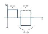
도 22는 단일 작동 회전-진동 장치의 작동 챔버 내의 압력 시간에 따른 변화(실선)를 도시하고, 피스톤의 완전한 회전을 거치는 동안에 얻어지는 유속(점선)을 도시하는 간략화한 그래프이다. 상기 그래프는 아래 기재된 변이 상태를 도시하지는 않는다.
도 23은 이중 작동 회전-진동 장치의 작동 챔버의 각 챔버 내의 압력 시간에 따른 변화(실선 및 점선)를 도시하고, 피스톤의 완전한 회전을 거치는 동안에 얻어지는 유속(점선)을 도시하는 간략화한 그래프이다. 상기 그래프는 아래 기재된 변이 상태를 도시하지 않는다.
도 24는 서로 평행인 엔드피스를 갖는 회전-진동 서브어셈블리의 중공체의 사시도이다.
도 25는 도 24의 회전-진동 서브어셈블리의 중공체의 덕트의 축 상에 놓인 평면의 방사상 단면도이다.
도 13 내지 도 20에서, 이전 도면에서의 부품과 유사한 부품은 동일한 참조 번호에 100을 더하여 나타난다.By way of non-limiting example, the present invention may be better understood and other advantages are obtained by reading the detailed description of the two embodiments shown in the accompanying drawings.
1 to 3 are front views of a piston with a sealing gasket of a rotational-vibration subassembly according to a first embodiment of the present invention shown in three different directions.
Fig. 4 is a perspective view of the sealing gasket of Figs. 1-3;
5 is a perspective view of the piston end of Figs. 1-3 with a sealing gasket;
6-11 are projected elevational views of a rotary-vibration subassembly of a first embodiment of the present invention shown in six separate operating positions during a pumping cycle (suction, switch, discharge, switch).
Fig. 12 is a sectional view of the piston and the hollow body of the first embodiment of the present invention, showing the functional angle of the sealing line of the sealing gasket with respect to the positioning and size setting of the duct, from above. In geometry, only one angle of each angle is shown.
13 and 14 are exploded perspective and broken perspective views, respectively, of a rotational-vibration subassembly in accordance with a second embodiment of the present invention.
Figs. 15-20 are cross-sectional views of the rotation-vibration subassembly of Figs. 13 and 14 shown at six distinct operating positions during a pumping cycle.
Figure 21 is a perspective view of the hollow body of the rotating-vibration subassembly of Figures 1-11 showing the connector end piece positioned 180 degrees.
22 is a simplified graph showing the pressure-time variation (solid line) in the operation chamber of the single operation rotary-vibration device and the flow rate (dotted line) obtained during the complete rotation of the piston. The graph does not show the mutation state described below.
23 is a simplified graph showing the pressure-time variation (solid line and dotted line) in each chamber of the operation chamber of the dual operation rotary-vibration device and the flow rate (dotted line) obtained during the complete rotation of the piston. The graph does not show the mutation state described below.
24 is a perspective view of a hollow body of a rotating-vibration subassembly having end pieces parallel to each other.
25 is a radial cross-sectional view of the plane lying on the axis of the duct of the hollow body of the rotational-vibration subassembly of FIG.
In Figs. 13 to 20, parts similar to those in the previous drawings are indicated by adding 100 to the same reference numerals.
본 발명의 회전-진동 펌핑 서브어셈블리는 도 1 내지 도 11에서 도시한 제 1 실시형태로서 하기 기재된 바와 같이 단일 스테이지를 가지는 단일 작동 구성 또는 예를 들면 도 12 내지 도 19에 도시한 제 2 실시형태로 하기 기재된 이중 작동 구성과 같이 복수의 스테이지를 가지는 다중 작동을 나타낸다.The rotary-vibration pumping subassembly of the present invention may be used in a single operating configuration having a single stage as described below as the first embodiment shown in Figs. 1-11 or in a second operating configuration shown in Figs. 12 to 19 Lt; RTI ID = 0.0 > a < / RTI > dual operating configuration as described below.
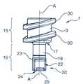
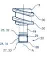
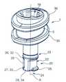
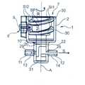
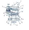
도 6 내지 도 11을 참조하면, 본 발명의 제 1 실시형태의 회전-진동 서브어셈블리(1)는 중공체(2)와 피스톤(3)으로 구성된다.Referring to Figs. 6-11, the rotational-
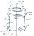
도 7에 상세히 나타난 바와 같이, 속이 빈 중공체(2)는 숄더(6)를 통해 서로 연결된 직경이 다른 두 개의 원통형부(4, 5)로 형성된다. 예를 들면, 중공체(2)는 플라스틱 소재 또는 임의의 다른 적절한 소재로 이루어진다.As shown in detail in Fig. 7, the hollow
대 직경 원통형부(4)의 내부는 종축(A)의 보어(7)를 형성한다. 대 직경 원통형부(4)의 자유 단부는 개방되어 있고, 종 방향 슬라이딩 시 피스톤(3)을 수용하기 위한 것이다. 다른 단부는 숄더(6)를 통해 소 직경 원통형부(5)에 연결된다. 대 직경 원통형부(4)의 벽은 보어(7) 안으로 연장되도록 배치된 방사형 가이드 핑거를 수용하기 위해 그 안을 통과하는 오리피스(8)를 가진다. 나타난 실시형태에서, 가이드 핑거(9)는 핀이다. 또한, 가이드 핑거(9)는 접착제 또는 임의의 다른 적절한 수단에 의해 중공체에 고정될 수 있다. 예를 들면, 가이드 핑거(9)는 원통형부분 또는 임의의 다른 적절한 부분을 나타낸다.The inside of the large-diameter
소 직경 원통형부(5)의 내부는 종축(A)의 캐비티(10) 및 보어(7)의 직경보다 작은 직경을 규정한다. 소 직경 원통형부(5)의 자유 단부는 폐쇄되어 있고, 중공체(2)의 바닥을 형성한다. 보어(7)와 캐비티(10)는 중공체(2)에 내제된 피스톤(3)을 수용하기 위한 것이다. 소 직경 원통형부(5)의 벽은 그 벽을 관통하여 방사상으로 캐비티(10) 안으로 들어가서 나오는 두 개의 덕트(11, 12)를 가진다. 예를 들면, 덕트(11, 12)은 원형인 부분을 가지며, 동일한 직경을 나타내며, 동일한 축 상에서 직경 상 서로 맞은 편에 있으며, 종축(A)에 수직인 동일한 방사형 평면에 위치한다. 따라서, 이 실시형태에서 캐비티(10) 안으로 난 덕트(11, 12)의 구멍은 동일한 축 상에서 직경 상 서로 맞은 편에 있으며, 동일한 방사형 평면에 위치한다. 특히, 도 21에 나타난 바와 같이, 중공체(2)는 각각의 덕트(11, 12)를 개별적으로 둘러싸고, 흡입 파이프 또는 배출 파이프 또는 임의의 다른 적절한 유체-흐름 연결 장치에 연결하기 위한 적절한 연결기 엔드피스(13, 14)를 포함한다. 따라서, 연결기 엔드피스(13, 14)는 180도의 각도만큼 서로 오프셋된다. 하기 기재된 바와 같이, 선택된 작동 구성에 따라서, 각각의 덕트(11, 12)은 유체를 흡입 또는 배출하는 데 동등하게 잘 사용될 수 있다.The inside of the small diameter
다른 실시형태(나타나지 않은)에서, 덕트는 서로가 약간 종 방향으로 오프셋될 수 있다.In another embodiment (not shown), the ducts may be slightly offset from one another in the longitudinal direction.
도 24 및 도 25에 나타난 실시형태에서, 각각의 덕트(11, 12)은 엔드피스가 180도가 아닌 각도를 나타낼 수 있게 하는 벤드(bend)를 갖는 반면, 덕트의 구멍은 180도의 각도만큼 서로 오프셋될 수 있다. 이 실시형태에서, 연결기 엔드피스(13, 14)는 서로 평행이며, 이것은 유체-흐름 연결의 구성을 단순화시킨다. 동일한 원리로, 180도의 각도만큼 서로 오프셋된 덕트의 구멍을 가지면서, 그 사이 임의의 다른 적절한 각도를 나타내는 연결기 엔드피스(13, 14)를 갖는 것이 가능하다. 180도가 아닌 각도만큼 오프셋된 덕트 구멍에도 동일한 원리가 적용된다.In the embodiment shown in FIGS. 24 and 25, each
다른 실시형태에서, 덕트는 또한 180도가 아닌 각도만큼 서로 오프셋될 수 있다.In another embodiment, the ducts may also be offset from one another by an angle other than 180 degrees.
특히 도 1 내지 도 5를 참조하면, 피스톤(3)은 숄더(17)를 통해 서로 연결된 직경이 다른 두 개의 원통형부(15, 16)로 만들어진다. 예를 들면, 피스톤은 플라스틱 소재 또는 임의의 다른 적절한 소재로 만들어진다.1 to 5, the
피스톤(3)의 소 직경 원통형부(16)는 캐비티(10)의 직경보다 작은 외부 직경을 나타내며, 이에 따라서 수납될 수 있다. 나타난 실시형태에서, 피스톤(3)의 소 직경 원통형부(16)는 두 개의 부 즉, 피스톤(3)의 부분과 일체로 만들어지고 직경이 감소된 샤프트(19)와 샤프트(19)의 감소된 직경 부에 맞고 샤프트(19)의 외부 직경에 상응하는 외부 직경을 갖는 슬리브(20)로 만들어진다. 피스톤(3)의 소 직경 원통형부(16)는 단일 피스로도 만들어질 수 있다.The small diameter
도 4를 참조하면, 슬리브(20)는 축 리세스(21)를 포함하며 예를 들면, 그것은 선택적으로 접착제 또는 임의의 다른 적절한 고정 수단으로 힘 맞춤에 의해 샤프트(19)에 고정된다. 또는, 슬리브(20)는 샤프트(19) 상에 오버몰드됨으로써 이루어질 수 있다. 특히 도 6 내지 도 10을 참조하면, 슬리브(20)의 자유 단부는 유체를 수용하기 위한 작동 챔버(31)를 규정하는 중공체(2)의 바닥과 협력한다.Referring to Fig. 4, the
그 주변부에 있어서, 슬리브(20)는 피스톤(3)의 대 직경 원통형부(15)를 향해 배향된 폐쇄 단부(23)와 작동 챔버(31) 안으로 개방된 개방 단부(24) 사이에서 종 방향으로 연장되는 채널(22)을 포함한다. 나타낸 실시형태에 있어서, 채널(22)의 바닥은 종축(A)에 대해 평행인 볼록 커브형 프로파일을 나타낸다. 프로파일은 예를 들면, 면을 가지며 평평하거나, 커브형 리세스 또는 임의의 다른 적절한 프로파일과 같이 다를 수 있다. 나타낸 실시형태에 있어서, 채널(22)은 종축(A)에 실질적으로 평행인 종 방향 엣지와 원형으로 아치형인 횡 엣지에 의해 규정되며, 각각의 횡 엣지는 종축(A)에 실질적으로 수직인 평면에 위치한다. 따라서 채널(22)은 튜브의 일부분의 형상을 일반적으로 나타낸다. 또한, 채널(22)은 경사선 형상, 십자 형상 또는 피스톤(3)의 회전-진동 이동에 적합화된 임의의 다른 형상을 나타낼 수 있다. 이것의 개방 단부(24)에서, 슬리브(20)는 채널(22) 내에 제공되고, 또한 유체가 그 측면을 통과할 수 있도록 그 주변부는 캐비티(10)에 대해 베어링하면서 방사상으로 연장된 평형 러그(25)를 포함한다. 예를 들면, 평형 러그(25)는 채널(22)의 중앙에 제공된다.At its periphery, the
특히 도 4를 참조하면, 슬리브(20)는 환상 그루브(26), 반환상 그루브(27) 및 환상 그루브(26)와 반환상 그루브(27)를 서로 연결시키는 두 개의 종 방향 그루브(28)로 이루어진 주변부 그루브가 제공된다. 다양한 실시형태(도시하지 않음)에서, 슬리브는 단일 종 방향 그루브를 포함한다.4,
피스톤(3)이 중공체(2) 내에 있을 경우, 심지어 피스톤(3)이 그것의 낮은 위치에 있을 경우, 환상 그루브(26)는 종축(A)에 수직인 평면에 형성되며, 동일한 채널(22)의 개방 단부(24)에 대해 채널(22)의 폐쇄 단부(23)를 지나고, 작동 챔버(31)에 대해 덕트(11, 12)를 지나서 축 방향으로 위치하여 있다.When the
반환상 그루브(27)는 종축(A)에 수직인 평면에서 환상 그루브(26)에 평행하게 형성되고, 채널(22)의 개방 단부(24)에 축 방향으로 위치하여 있다. 따라서, 피스톤(3)이 중공체(2) 내에 있을 경우, 심지어 높은 위치에 있을 경우, 반환상 그루브(27)는 덕트(11, 12)와 작동 챔버(31) 사이에서 축 방향으로 배치된다.The annular groove 27 is formed parallel to the annular groove 26 in a plane perpendicular to the longitudinal axis A and is axially positioned at the
나타낸 실시형태에서, 종 방향 그루브(28)는 종축(A)에 평행하게 형성되고, 환상 그루브(26)와 반환상 그루브(27)의 단부는 서로 연결되어 있다. 따라서, 채널(22)은 첫 번째로 종 방향 그루브(28)와, 두 번째로 환상 그루브(26)의 일부 사이에 놓인다. 또한, 종 방향 그루브(28)는 종축(A)을 따라 변하는 폭을 가질 수 있고, 예를 들면, 모래시계 형상을 나타낸다.In the embodiment shown, the
그 주변부에 있어서, 슬리브(20)는 또한 채널(22)에 각이 져서 맞은 편에 있는 폐쇄 리세스존(29)을 포함한다. 각각의 종 방향 그루브(28)는 채널(22)과 리세스존(29) 사이에 배치된다. 따라서 리세스존(29)은 첫 번째로 종 방향 채널(28)과 두 번째로 반환상 채널(27) 및 환상 채널(26)의 일부 사이에 위치한다. 리세스존(29)은 캐비티(10)와 접촉하는 피스톤(3)의 표면 넓이를 제한하는 것을 가능하게 하여 마찰을 제한할 수 있다. 따라서, 피스톤(3)의 회전-진동 이동은 고 에너지 효율성으로 일어난다.At its periphery, the
작동 챔버(31)에 대향하는 피스톤(3)의 소 직경 원통형부(16)의 단부는 동일한 피스톤(3)의 대 직경 원통형부(15)에 연결된다.The end of the small diameter
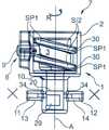
피스톤(3)의 대 직경 원통형부(15)는 보어(7)의 직경보다 작은 외부 직경을 나타내어 수납될 수 있다. 대 직경 원통형부(15)의 자유 단부는 중공체(2)에 대해 피스톤(3)을 회전하기 위한 구동 수단에 연결되는 상보적인 형상의 엔드피스(나타나지 않은)를 수용하기 위해 크로스 형상(도 5에서 알 수 있는 바와 같이)인 리세스 형상(18)을 나타낸다. 리세스 형상(18)은 회전 구동에 적절한 임의의 다른 프로파일을 가질 수 있고, 또한 릴리프부로서 제공될 수 있다. 그러나, 리세스 형상은 접근성이 적은 이점을 나타내어, 피스톤(3)의 위치가 회전-진동 서브어셈블리(1)를 사용하기 전에 수동으로 덜 쉽게 변경된다. 따라서, 그 첫번째 사용으로부터, 피스톤의 위치는 알고 있으므로, 초기 가동시 피스톤의 작동 스테이지를 확실하게 할 수 있고, 따라서 전송된 투여량을 정확하게 알 수 있다. 동일한 이유로, 리세스 형상은 작동되기 위해 특정 도구의 사용을 요구하도록 디자인될 수 있다. 피스톤(3)의 대 직경 원통형부(15)는 서로 평행한 두 개의 환상 리브(30)를 포함하여 그들 사이에서 가이드 핑거(9)를 가이딩하기 위한 듀얼 가이드 캠을 규정한다. 따라서, 가이드 핑거(9)에 대해 회전하는 어떤 위치에서도, 환상 리브(30) 사이의 종 방향의 스페이싱은 가이드 핑거(9)의 치수에 조절되어 간극 없이 또는 초과 간극 없이 가이딩을 가능하게 한다. 또한, 가이드 핑거(9)는 환상 리브(30)에 대해 롤링하는 회전부가 제공될 수 있어서, 마찰을 감소시킨다. 따라서 에너지 효율성은 최적화된다. 환상 리브(30)의 각 리브는 종 방향 중앙 평면에서 서로가 대칭인 제 1 경사부 및 제 2 경사부(SI1, SI2)를 포함한다. 따라서, 제 1 경사부 및 제 2 경사부(SI1, SI2)는 피스톤(3)의 주변부에서 대향하는 경사를 나타낸다. 제 1 경사부 및 제 2 경사부(SI1, SI2)는 서로가 실질적으로 평행이며 종축(A)에 수직인 제 1 및 제 2 평면부(SP1, SP2)에서 서로가 떨어져서 이간된다. 따라서, 가이드 핑거(9)와 환상 리브(30)에 의해, 피스톤(3)이 제 1 회전 방향(R)으로 중공체(2)에 대해 회전됨으로써, 연속으로 피스톤(3)이 제 1 경사부(SI1)를 따라 제 1 이동 방향(T1)으로 중공체(2)에 대해 축 방향으로 이동되게 되고, 그 뒤에 제 2 경사부(SI2)를 따라 제 2 이동 방향(T2)으로 축 방향으로 중공체(2)에 대해 이동되게 되고, 뒤에 최종적으로 제 2 평면부(SP2)를 따라 중공체(2)에 대해 축 방향으로 정지되게 되는 등 한다. 따라서, 피스톤(3)은 작동 챔버(31)가 최대 용적을 나타내는 높은 위치(도 8과 비교)와 작동 챔버(31)가 최소 부피를 나타내는 낮은 위치 사이에서 왕복 운동을 한다. 피스톤(3)의 두 위치 사이에서, 작동 챔버(31)는 유체를 투입한 후 배출한다.The large-diameter
피스톤(3)은 주변부 그루브에 수납되고 피스톤(3)과 중공체(2)의 탄성 계수보다 작은 탄성 계수를 가지는 소재로 이루어진 실링 개스킷을 지닌다. 예를 들면, 그것은 탄성 중합체로 이루어지고, 피스톤(3)이 캐비티(10) 내에 있을 경우, 실링 개스킷은 캐비티(10)의 내벽과 접촉하도록 치수 설정된다.The
실링 개스킷은 동축 상에 있고 서로 평행이며, 두 개의 실링 스트립(34)에 의해 서로 연결된 실링 링(32)과 실링 하프링(half-ring)(33)으로 형성된다. 피스톤이 단일의 종 방향 그루브만을 갖는 경우, 실링 개스킷은 단일의 실링 스트립만을 포함한다.The sealing gasket is coaxially and parallel to one another and is formed by a sealing ring 32 and a sealing half-ring 33 interconnected by two sealing strips 34. If the piston has only a single longitudinal groove, the sealing gasket comprises only a single sealing strip.
나타낸 실시형태에서, 실링 스트립(34)은 서로로부터 180도로 배치된다. 하지만, 실링 스트립(34)은 하기 기재된 기하학적 제한 사항을 따르는 조건 하에 다르게 배치될 수 있다. 실링 스트립(34)은 종축(A)을 따라 일정한 폭 또는 채널(22)의 변하는 폭에 적응하기 위한 변하는 폭을 가질 수 있다.In the embodiment shown, the sealing strips 34 are disposed 180 degrees from each other. However, the sealing strips 34 may be deployed differently under conditions that conform to the geometric limitations described below. The sealing
실링 링(32)은 환상 그루브(26) 내에 수납되며, 실링 하프링(33)은 반환상 그루브(27) 내에 수납되고, 각각의 실링 스트립(34)은 종 방향 그루브(28)의 각각의 그루브 내에 수납된다. 따라서, 중공체(2) 중의 피스톤(3)의 임의의 각 위치 및 축 위치에서도, 실링 링(32)은 작동 챔버(31)에 대해 덕트(11, 12)를 축 방향으로 지나 위치되며, 실링 하프링(33)은 덕트(11, 12)와 작동 챔버(31) 사이에서 축 방향으로 위치된다. 실링 개스킷은 리세스존(29) 주위 및 채널(22)과 작동 챔버(31) 주위에 실링을 제공하여, 채널(22)과 작동 챔버(31) 사이에서 유체-흐름 연통을 확실케 하도록 한다.The sealing ring 32 is housed within the annular groove 26 and the sealing half ring 33 is accommodated within the annular groove 27 and each sealing
각각의 실링 스트립(34)은 서로가 각이 져서 오프셋된 제 1 및 제 2 실링선(L1, L2)(도 4 및 도 12에 나타난)을 규정한다. 도 12에 나타난 바와 같이, 채널(22)은 두 개의 실링 스트립(34)의 각 스트립의 제 1 실링선(L1)에 의해 각이 져서 접하며, 리세스존(29)은 두 개의 실링 스트립(34)의 각 스트립의 제 2 실링선(L2)에 의해 접한다. 리세스존(29)은 캐비티(10)와 접촉하는 실링 개스킷 넓이를 제한하는 것을 가능하게 하여 마찰을 줄인다. 동일한 이유로, 각각의 실링 스트립은 나타내지 않은 다양한 실시형태에 있어서는 매립될 수 있다.Each of the sealing strips 34 defines a first and a second sealing line L1, L2 (shown in Figures 4 and 12) that are angled relative to each other and offset. The
특히 도 12를 참조하면, 중공체(2), 피스톤(3) 및 실링 개스킷은 다음의 기하학적 제한 사항을 따르도록 배치된다:12, the
제 1 실링선(L1)은 덕트(11, 12) 중 어느 하나의 덕트의 엣지 사이의 각도(β1)의 각각의 각도보다 크고, 덕트(11)의 인접하는 엣지와 그것의 상응하는 덕트(12)의 인접하는 엣지 사이의 각도(β2)의 각각의 각도보다 작은, 채널을 포함하는 각도(α1)로 서로 떨어져 이간된다.The first sealing line L1 is larger than each angle of the
각각의 제 2 실링선(L2)은 채널(22)을 포함하지 않고, 각도(β2)의 각각의 각도보다 작으며, 각도(β1)의 각각의 각도보다 큰 각도(α2)로 제 1 실링선(L1) 중의 하나에 의해 떨어져 이간된다.Each second sealing line L2 does not include a
각각의 제 1 실링선(L1)과 적어도 하나 이상의 제 2 실링선(L2) 사이의 각도(α3)는 채널(22)을 포함하며 두 개의 덕트(11, 12)의 축 방향으로 대향하는 엣지 사이의 각도(β3)보다 크다.The angle? 3 between each first sealing line L1 and the at least one second sealing line L2 includes a
따라서, 단일 작동 회전-진동 서브어셈블리(1)는 두 개의 덕트(11, 12), 작동 챔버(31), 채널(22) 및 리세스존(29)을 포함하는 단일 스테이지가 제공된다. 따라서, 단일 채널(22)은 덕트(11, 12)의 "흡입" 및 "배출" 짝에 상응한다.Thus, a single actuated rotary-
단일 작동 회전-진동 서브어셈블리(1)를 작동시키기 위해서는, 덕트(11, 12) 중 하나를 유체 이송 파이프에 연결하고, 다른 하나를 동일한 유체를 배출하기 위한 배출 파이프에 연결하고, 피스톤(3)을 리세스 형상(18)에 의해 공지된 유형의 회전 구동 수단(도시하지 않음)에 기계적으로 연결한다. 본 발명의 단일 작동 회전-진동 서브어셈블리(1)의 작동은 하기 도 6 내지 도 11 및 도 22의 그래프를 참조하여 후술한다.To actuate the single acting rotary-
도 6 및 도 7에 나타난 흡입 상태와 도 22에 나타난 "흡입 상태"에서, 가이드 핑거(9)는 주로 캠의 제 1 경사부(SI1)을 따라서 통과하며, 이것은 피스톤(3)의 회전 이동(R)을 중공체(2)에 상대적인 피스톤(3)의 제 1 이동 방향을 따라 제 1 이동(T1)으로 변환시키며, 피스톤(3)을 작동 챔버(31)가 최소 부피를 나타내는 낮은 위치(도 11)로부터 작동 챔버(31)가 최대 부피를 나타내는 높은 위치(도 7)까지 통과하도록 한다. 흡입 상태에서, 피스톤(3)은 중공체(2)에 대해 회전하며, 채널(22)은 "흡입" 덕트(11)의 오리피스 앞으로 통과한다. 따라서, "흡입" 덕트(11)는 채널(22)을 통하여 작동 챔버(31)와 유체-흐름 연통에 있고, 유체는 제 1 이동 (T1)에 의해 작동 챔버(31)의 증가된 부피만큼 흡입되어, 화살표(E)를 따라 작동 챔버(31)에서 흡입을 만든다. 흡입 상태에서, 리세스존(29)은 "배출" 덕트(12)의 오리피스 앞으로 통과한다. 실링 개스킷은 작동 챔버(31)와 유체-흐름 연통하여 있지 않은 "배출" 덕트(12)를 실링하고, 이것은 십자(+)로 나타낸다. 따라서, "흡입" 덕트(11)를 통한 흡입 상태 시에는, 유체는 "배출" 덕트(12)를 통해 작동 챔버(31)를 벗어나지 않는다. 피스톤(3)은 제 1 스위치 상태에 도달할 때까지 중공체(2)에 대해 회전(R)을 계속한다. 바람직한 방식으로, 흡입 상태 시작 시에 변이 상태 동안 가이드 핑거(9)는 제 2 평면부(SP2)의 단부를 지나 통과한다. 또한, 흡입 상태의 종료시에는 변이 상태 동안 가이드 핑거(9)는 캠의 제 1 평면부(SP1)의 시작점을 지나 통과한다. 따라서, 변이 상태는 작동 챔버(31)의 부피가 일정한 동안 발생한다. 간소화하기 위해, 변이 상태는 도 22에서 그래프에 도시하지 않는다.In the suction state shown in Figs. 6 and 7 and the "suction state" shown in Fig. 22, the
도 8에 도시한 제 1 스위치 상태 및 도 22에 도시한 "스위치 상태" 중 하나에서, 가이드 핑거(9)는 캠의 제 1 평면부(SP1)를 따라서 통과한다. 따라서, 피스톤(3)의 회전(R)에 의해 이것이 이동되지 않고, 피스톤(3)은 높은 위치에서 축 방향으로 정지된다. 따라서, 작동 챔버(31)의 부피는 변하지 않고 그 최대치에서 유지된다. 스위치 상태에서, "흡입" 및 "배출" 덕트(11, 12)의 오리피스의 각각의 오리피스는 "흡입" 또는 "배출" 덕트(11, 12) 중의 하나 또는 다른 하나와 임의의 유체-흐름 연통을 억제하는 각각의 실링 스트립(34)과 접한다. 따라서, 작동 챔버(31)는 누출밀봉 방식으로 폐쇄된다.In one of the first switch state shown in Fig. 8 and the "switch state" shown in Fig. 22, the
피스톤(3)은 배출 상태가 도달될 때까지 중공체(2)에 대해 회전(R)을 계속한다.The piston (3) continues to rotate (R) with respect to the hollow body (2) until the discharge state is reached.
도 9 및 도 10에 나타난 배출 상태와 도 22에 나타난 "배출 상태"에서, 가이드 핑거(9)는 주로 캠의 제 2 경사부(SI2)를 따라서 통과하고, 피스톤(3)의 회전(R)을 이동(T1) 도중에 제 1 이동 방향과 맞은 편인 제 2 이동 방향을 따라 제 2 이동(T2)으로 변환시킨다. 따라서, 피스톤(3)은 높은 위치(도 8)로부터 낮은 위치(도 11)까지 통과한다. 배출 상태에서, 피스톤(3)은 채널(22)이 "배출" 덕트(12)의 오리프스 앞으로 통과하면서, 중공체(2)에 대해 회전한다. 따라서, "배출" 덕트(12)는 채널(22)을 통하여 작동 챔버(31)와 유체-흐름 연통에 있으며, 유체는 화살표(S)를 따라 이동(T2)에서 제 2 이동에 의해 작동 챔버(31)의 부피가 감소되는 만큼 "배출" 덕트(12)을 통해 배출되며 작동 챔버(31)에서 고압을 형성한다. 배출 상태에서, 함몰 존(29)은 "흡입" 덕트(11)의 오리피스 앞을 통과한다. 실링 개스킷은 작동 챔버(31)와 유체-흐름 연통에 있지 않은 "흡입" 덕트(11)을 실링한다. 따라서, "배출" 덕트(12)을 통한 배출 상태에서 유체는 "흡입" 덕트(1)을 통하여 작동 챔버(31)로 들어가지 않는다. 피스톤(3)은 제 2 스위치 상태가 도달될 때까지 중공체(2)에 대해 회전(R)을 계속한다. 바람직한 방식으로, 배출 시작시에 변이 상태에서 가이드 핑거(9)는 제 1 평면부(SP1)를 지나 통과한다. 또한, 배출 상태끝에서 변이 상태도중 가이드 핑거(9)는 캠의 제 2 평면부(SP2)의 시작점을 지나 통과한다. 따라서, 변이 상태는 작동 챔버(31)의 부피가 일정한 동안 발생한다. 단순화를 위하여, 변이 상태는 도 22에서 그래프에 나타나지 않는다.The
도 11과 도 22에 나타난 다른 "스위치 상태"에 나타난 이러한 제 2 스위치 상태는 제 1 스위치 상태와 실질적으로 유사하다. 피스톤(3)이 낮은 위치에 있고, 작동 챔버(31)가 최소 부피를 나타내며, "흡입" 및 "배출" 덕트(11, 12)에 상대적인 실링 스트립(34)의 위치가 제 1 스위치 상태에 대해 도치된 점에서 다르다.This second switch state shown in another "switch state" shown in Figs. 11 and 22 is substantially similar to the first switch state. The position of the sealing
회전-진동 사이클은 반복될 수 있다. 자연스럽게, 중공체(2)에 대해 피스톤(3)의 회전 방향에 따라 "흡입" 덕트는 배출 덕트에 상응할 수 있고 반대도 가능하다. 캐비티(10)에서 피스톤(3)의 이동 중에, 평형 러그(25)와 캐비티(10)의 벽 간의 접촉은 마찰을 증가시키고 누출이 발생하며 심지어 중공체(2) 안에서 피스톤(3)의 재밍(jamming)을 일으키는 종축(A)에 대하여 피스톤(3)의 경사 현상을 방지한다.The rotation-oscillation cycle can be repeated. Naturally, depending on the direction of rotation of the
제 1 및 제 2 경사부(SI1, SI2)의 프로파일 및 제 1 및 제 2 실링선(L1, L2)의 위치 설정을 변경함으로써, 흡입 상태와 배출 상태간의 비율은 조절될 수 있다. 따라서, 흡입 및 배출 상태중의 일 상태의 지속 시간은 다른 상태의 지속 시간에 대해 연장될 수 있다.By changing the profile of the first and second slopes SI1 and SI2 and the positioning of the first and second sealing lines L1 and L2, the ratio between the suction state and the discharge state can be adjusted. Thus, the duration of one state during the inhalation and exhalation states can be extended to the duration of other states.
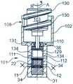
본 발명의 제 2 실시형태의 회전-진동 서브어셈블리(101)는 도 13 내지 도 20에 나타나고 이중 작동 구성을 나타낸다. 이러한 목적을 위하여, 그것은 두 스테이지로 구성되며, 회전-진동 서브어셈블리(1)의 상태와 유사한 제 1 스테이지와 제 1 스테이지와 유사하게 두 개의 덕트(11, 12), 작동 챔버(13), 채널(122), 리세스존(129)을 포함한 제 2 스테이지로 구성된다. 따라서, 단일 채널(22, 122)은 각각의 "흡입" 및 "배출" 덕트(11, 12)와 상응한다.The rotary-
나타난 실시형태에서, "흡입" 덕트(11, 111)는 종 방향으로 중첩되며, "배출" 덕트(12,112)도 종 방향으로 중첩되고, 채널(22, 122)은 서로 180도로 위치되며, 리세스존(29, 129)은 서로 180도의 각도만큼 위치된다. "흡입" 덕트(11, 111) 및 "배출" 덕트(12, 112)을 통한 유체-흐름 연결은 180도로 이루어진다. 중공체(102)는 더 큰 높이를 나타내는 캐비티(110)를 포함하여, 양 스테이지를 가지는 것을 가능하도록 한다. 중공체(102)는 또한 캐비티(110)와 보어(107)를 분리시키는 숄더(106)와 동일 평면이고, 중공체(102)의 내부로 배향되며, 추가적인 실링 개스킷(36)을 수용하거나 예를 들면, 피스톤(103)과 중공체(102) 간의 실링을 제공하는 임의의 다른 실링 부품을 수용하기 위한 환상 홈(135)을 포함한다. 따라서, 도 23의 그래프에 나타난 바와 같이, 채널(22, 122)이 "흡입" 덕트(11, 111)를 접하면서 일 스테이지가 "흡입 상태"에 있을 때, 채널(22, 122)이 "배출" 덕트(12, 112)와 접하면서 다른 스테이지가 "배출 상태"에 있는다(도 16, 17, 19 및 20). 회전-진동 서브어셈블리(1)와 같이, 스위치 상태에서 "흡입" 덕트(11, 111)과 "배출" 덕트(12, 112)는 누설 밀봉 방식으로 폐쇄된다(도 15 및 도 18).In the embodiment shown, the "suction"
제 1 구성에서, 각 스테이지의 "흡입" 덕트(11, 111)는 단일 유체를 위한 공통 입구와 유체-흐름 연결일 수 있고, 각 스테이지의 "배출" 덕트(12, 112)는 단일 유체를 위한 공통 출구와 유체-흐름 연결일 수 있다.In the first configuration, the "intake"
제 2 구성에서, 이중 작동 회전-진동 서브어셈블리는 제 1 유체를 위한 일 스테이지와 제 2 유체를 위한 다른 스테이지를 사용하여 혼합물을 만드는데 바람직하게 사용될 수 있고, 각 스테이지의 "배출" 덕트(12, 112)는 그 혼합물을 수용하기 위한 단일 컨테이너에 연결된다. 작동 챔버(31, 131)와 가능하다면 덕트(11, 111, 12, 112)의 부분 간의 비율을 변경함으로써 그 혼합물의 투여량을 변경하는 것은 가능하다.In a second configuration, the dual-actuated rotary-vibrating subassembly may be advantageously used to make a mixture using one stage for the first fluid and another stage for the second fluid, and the "exhaust"
이 두 구성에서, 그러한 이중 작동 회전-진동 서브어셈블리(101)를 결합한 펌핑 장치의 유속은 증가되며, 맥동 주파수는 단일 작동 회전-진동 서브어셈블리(1)의 두 배이다.In these two configurations, the flow rate of the pumping device incorporating such dual-acting rotational-
제 3 구성에서, 일 스테이지의 "배출" 덕트(12)는 다른 스테이지의 "흡입" 덕트와 유체-흐름 연결일 수 있다. 제 3 구성에서, 흡입 유체는 양 작동 챔버(31, 131)를 연속으로 통과한다. 각 스테이지에 의해 생성된 배출 압력은 따라서 캐스케이드로 늘어난다.In a third configuration, the "exhaust"
제 4 구성에서, 두 스테이지는 동일할 수 있고 종 방향으로 단순히 서로 오프셋될 수 있다. 따라서, 두 상태의 두 흡입 스테이지는 동시에 일어나며, 두 상태의 두 배출 스테이지는 동시에 일어난다. 이 구성에서, 그러한 이중 작동 회전-진동 서브어셈블리(101)를 결합한 펌핑 장치의 유속은 두 배가 되며, 맥동 진동수는 단일 작동 회전-진동 서브어셈블리(1)와 동일하다.In a fourth configuration, the two stages can be identical and can simply offset each other in the longitudinal direction. Thus, two suction stages in two states occur simultaneously, and two discharge stages in both states occur at the same time. In this configuration, the flow rate of the pumping device incorporating such dual-acting rotational-
다른 실시형태(나타나지 않은)에서, 각각의 "흡입" 덕트는 기결정 각도만큼 상응하는 "배출" 덕트으로부터 각이 져서 오프셋되며, 채널은 동일한 기결정 각도만큼 서로 각이 져서 오프셋되고, 리세스존은 또한 동일한 기결정 각도만큼 각이 져서 오프셋된다. "흡입" 및 "배출" 덕트을 통한 유체-흐름 연결은 기결정 각도만큼 각이 져서 오프셋된 개별 종 방향 평면에 있다. 각도는 유체-흐름 연결의 3차원 구성을 원활히 하기 위해 선택될 수 있다. 이러한 실시형태는 상기 상세히 기재된 다양한 구성과 결합될 수 있다.In another embodiment (not shown), each "suction" duct is angled and offset from the corresponding " exhaust "duct by a predefined angle, the channels are angled and offset from each other by the same predefined angle, Are also angled and offset by the same predefined angles. The fluid-flow connections through the "suction" and "discharge" ducts are angled by a predetermined angle and are offset in individual longitudinal planes. The angle can be selected to facilitate the three-dimensional configuration of the fluid-flow connection. These embodiments may be combined with the various configurations described in detail above.
본 발명은 상기 기재된 목적을 달성하는 것을 가능하게 한다. 구체적으로, 본 발명의 회전-진동 서브어셈블리(1, 101)는 제한된 수의 부품으로 제작하는 것이 단순하다. 실링 개스킷은 회전-진동 서브어셈블리(1, 101)에 따라서 기하학적 제한 사항을 제한하고 회전-진동 서브어셈블리(1, 101)를 더 쉽게 생산하는 것을 가능하게 한다. 조립하는 것은 더 쉬우며, 리세스존(29, 129)은 그 에너지 효율성을 향상시키는 것을 가능하게 한다.The present invention makes it possible to achieve the objects described above. Specifically, the inventive rotary-
회전-진동 서브어셈블리(1, 101)는 사용자 및/또는 유체의 점성과 관계없이 정확한 유속을 확실케 하는 것을 가능하게 한다. 그것은 각-위치 센서와 결합될 수 있다.The rotating-vibration subassembly (1, 101) makes it possible to ensure an accurate flow rate regardless of the viscosity of the user and / or fluid. It can be combined with an angle-position sensor.
또한, 본 발명의 회전-진동 서브어셈블리(1, 101)는 피스톤(3, 103)이 회전되는 방향을 단순히 역으로 함으로써 가역 가능하다. 따라서, "흡입" 덕트(11, 111)는 "배출" 덕트(12, 112)이 되고 반대도 가능하다. 모터 부가 재사용 가능한 반면피스톤(3, 103)과 구동 수단 간 기계적 분리는 일회용 회전-진동 서브어셈블리를 얻는 것을 가능하게 한다. 따라서, 두 사용 간에 그것을 교체함으로써 회전-진동 서브어셈블리(1, 101)가 저가에 무균이라는 것을 확실케 하는 것은 가능하다. 따라서, 회전-진동 펌핑 장치의 유체-흐름 부만이 재생되고, 모터 및 제어 부는 두 사용 간에 보전된다. 축력이 캠에 의해 전달되기 때문에, 회전만 하는 구동 수단을 사용하고 피스톤(3) 및 토크만을 전달하는 구동 수단 간의 기계적 결합 수단을 사용하는 것이 가능하다. 또한, 캠은 피스톤(3)의 이동에서 진동 이동이 그 피스톤(3)을 회전하는 것과 동시에 일어나는 것을 확실케 할 수 있다.In addition, the inventive rotary-vibration subassembly (1, 101) is reversible by simply reversing the direction in which the piston (3, 103) is rotated. Thus, the "inhaled"
본 발명의 회전-진동 서브어셈블리(1, 101)는 스위치 상태에서 "흡입 및 배출" 덕트(11, 111, 12, 112)에서 임의의 유체 흐름을 방지하지만, 이러한 상태에서 수력 블록킹에 의해 과도한 압력 또는 흡입 효과가 발생하지 않는다.The rotary-
실링 개스킷과 중공체 간의 접촉은 회전-진동 서브어셈블리(1, 101)의 위치를 그 초기 조립 도중에 각이 져서 설정하는 것을 가능하게 한다. 따라서 각진 설정은 회전-진동 서브어셈블리(1, 101)가 회전-진동 장치에서 작동될 때까지 쉽게 보전된다. 그럼에도 불구하고, 중공체(2, 102)에 상대적인 피스톤(3, 103)의 각진 위치의 가시 마크 또는 임의의 적절한 기술의 센서를 제공하는 것은 가능하다.The contact between the sealing gasket and the hollow body enables angular positioning of the rotational-
자연스럽게, 본 발명은 실시형태의 상기 기재에 제한되지 않으며, 본 발명의 범위를 벗어나지 않으며 다양한 변경에 영향받을 수 있다.
Naturally, the present invention is not limited to the above description of the embodiments, but may be modified in various manners without departing from the scope of the present invention.
Claims (9)
Translated fromKorean상기 캐비티(10; 110)에 수납되고, 작동 챔버(31; 131)를 규정하도록 협력하고, 또한 그 원통형 표면에는 일종의 종 방향 채널(22; 122) 또는 상기 작동 챔버(31; 131) 내로 종 방향으로 개방된 리세스를 포함하는 피스톤(3; 103);을 포함하는 유체의 용적형 펌핑을 위한 회전-진동 서브어셈블리(1; 101)로서,
상기 피스톤(3; 103)은, 상기 피스톤(3; 103)과 상기 중공체(2; 102)의 탄성 계수보다 작은 탄성 계수를 갖는 소재로 이루어지고, 또한, 상기 피스톤(3; 103)에 구비되는 실링 개스킷을 구비하고,
상기 실링 개스킷은 상기 피스톤(3; 103)과 상기 캐비티(10; 110) 간의 누설 밀봉을 보장하도록 상기 채널을 따라 연결되고,
상기 피스톤은, 상기 작동 챔버(31; 131)를 상기 적어도 두 개의 덕트(11, 12; 111, 112) 중 적어도 하나와 유체-유동 연통된 후, 상기 적어도 두 개의 덕트(11, 12; 111, 112) 중 어느 것과도 유체-유동 연통되지 않은 후, 상기 적어도 두 개의 덕트(11, 12; 111, 112) 중 다른 하나와 유체-유동 연통되도록, 각을 이루며 이동 가능하고,
또한, 상기 피스톤은, 상기 작동 챔버(31; 131)의 부피를 변화시켜서 상기 적어도 두 개의 덕트(11, 12; 111, 112) 중 하나를 통하여 상기 유체를 연속적으로 흡입한 후 상기 적어도 두 개의 덕트(11, 12; 111, 112) 중 다른 하나를 통해 상기 유체를 배출하도록, 종 방향으로 왕복 이동 가능하며,
상기 서브어셈블리는, 상기 피스톤이 서로 떨어져 있는 제 1 축 단부와 제 2 축 단부를 포함하고, 상기 제 2 축 단부는 상기 작동 챔버와 접촉하는 것을 특징으로 하며,
상기 실링 개스킷은,
상기 실링 개스킷의 제 1 축 단부 측면에서 상기 피스톤의 상기 원통형 표면 주위로 연장되는 링 형상이며, 실링 링(32)을 포함하는 제 1 실링 부분;
상기 실링 개스킷의 제 2 축 단부 측면에서 상기 피스톤의 상기 원통형 표면 주위로 연장되는 하프링 형상이며, 실링 하프링(33)을 포함하는 제 2 실링 부분,-상기 실링 하프링(33)은 상기 피스톤(3; 103)의 원통형 주변부에 대해서 서로 떨어져 이간된 두 개의 단부를 가짐-; 및
상기 실링 하프링(33)의 제 1 단부와 상기 실링 링(32) 사이와, 상기 실링 하프링(33)의 제 2 단부와 상기 실링 링(32) 사이 각각에 상기 피스톤의 외부 표면에 대해 축 방향으로 연장되는 두 개의 실링 스트립(34)에 의해 형성되는 제 3 실링 부분;을 포함하는 복수의 부분으로 구성되고,
상기 두 개의 실링 스트립은 각도적으로 서로 구분되고, 각각의 실링 스트립은,
상기 채널(22; 122)과 각이 져서 접하여 있는 제 1 실링선(L1)으로서, 상기 적어도 두 개의 덕트(11, 12; 111, 112) 중 어느 하나의 대향하는 엣지들 사이의 각각의 각도(β1)들 보다 크고, 또한, 상기 흡입 덕트(11; 111)와 이것과 상응하는 배출 덕트(12; 112) 중 어느 하나에 인접한 엣지들 사이의 각각의 각도(β2)들보다 작은, 상기 채널(22; 122)을 포함하는 제 1 각도(α1)만큼 서로 이간되어 있는 제 1 실링선(L1)들, 및
제 2 실링선(L2)으로, 상기 흡입 덕트(11; 111)들과 이것과 상응하는 배출 덕트(12; 112) 중 어느 하나의 인접한 엣지들 사이의 각각의 각도(β2)들보다 작으며, 또한, 상기 적어도 두 개의 덕트(11, 111; 12, 112) 중 어느 하나의 대향하는 엣지들 사이의 각각의 각도(β1)들 보다 큰, 상기 채널(22; 122)을 포함하지 않는, 제 2 각도(α2)만큼 상기 제 1 실링선(L1) 중의 하나로부터 이간되어 있는 제 2 실링선;을 규정하고,
상기 채널(22; 122)을 포함하는 제 3 각도(α3)로서, 상기 제 2 실링선(L2)의 적어도 하나로부터 각각의 상기 제 1 실링선(L1) 사이의 제 3 각도(α3)는, 상기 적어도 두 개의 덕트(11, 12; 111, 112)의 축 방향으로 대향하는 엣지 사이의 각도(β3)보다 큰 것을 특징으로 하는 회전-진동 서브어셈블리(1; 101).At least two ducts (11, 12; 111, 112) defining a cylindrical cavity (10; 110) of the longitudinal axis (A) and including a suction duct (11; 111) and a corresponding discharge duct , Said at least two ducts (11, 12; 111, 112) being radially open into said cavity (10; 110) and said hollow body (2; 102; ); And
And is housed in the cavity (10; 110), cooperating to define an actuating chamber (31; 131), and also has a cylindrical surface on its longitudinal axis (22; 122) And a piston (3; 103) including a recess that is open to the bottom of the piston (3; 103)
The piston (3; 103) is made of a material having an elastic modulus smaller than that of the piston (3; 103) and the hollow body (2; 102) And a sealing gasket,
The sealing gasket is connected along the channel to ensure leakage seal between the piston (3; 103) and the cavity (10; 110)
Wherein the piston is in fluid communication with at least one of the at least two ducts (11, 12; 111, 112) after the operating chamber (31; 131) 112, 111, 112) in fluid-communication with the other of the at least two ducts (11, 12; 111, 112)
In addition, the piston may be configured to continuously vary the volume of the operating chamber 31, 131 to continuously suck the fluid through one of the at least two ducts 11, 12, 111, 112, Is reciprocatable in a longitudinal direction so as to discharge the fluid through the other one of the fluid passages (11, 12; 111, 112)
Wherein the subassembly includes a first axial end portion and a second axial end portion at which the pistons are spaced from each other, and the second axial end portion is in contact with the operation chamber,
The sealing gasket
A first sealing portion that is ring-shaped and extends around the cylindrical surface of the piston at a first axial end side of the sealing gasket, the sealing portion including a sealing ring (32);
A second sealing portion that is in the form of a half-ring extending around the cylindrical surface of the piston at the second axial end side of the sealing gasket and includes a sealing half-ring 33, the sealing half- 103) having two ends spaced apart from each other with respect to a cylindrical peripheral portion thereof; And
(34) between the first end of the sealing half ring (33) and the sealing ring (32) and between the second end of the sealing half ring (33) and the sealing ring And a third sealing portion formed by two extending sealing strips 34,
Wherein the two sealing strips are angularly separated from one another,
A first sealing line L1 angularly abutting with the channel 22 122. The angle between each of the opposing edges of any one of the at least two ducts 11, 12, 111, and smaller than respective angles? 2 between edges adjacent to one of the intake ducts (11; 111) and the corresponding exhaust ducts (112; 112) First sealing lines L1 spaced apart from each other by a first angle alpha 1 including the first sealing line L1,
Is a second sealing line L2 that is smaller than an angle? 2 between the adjacent edges of either of the suction ducts 11, 111 and the corresponding exhaust duct 12, 112, Also, it is preferred that the second (22), which does not comprise the channel (22; 122), greater than the respective angles (? 1) between the opposing edges of any of the at least two ducts Defines a second sealing line spaced apart from one of the first sealing lines (L1) by an angle (? 2)
Wherein a third angle (? 3) between the first sealing line (L1) and at least one of the second sealing lines (L2) Is greater than an angle (? 3) between axially opposing edges of said at least two ducts (11, 12; 111, 112).
상기 피스톤(3; 103)은 상기 실링 개스킷을 수용하는 주변 그루브를 포함하고, 상기 주변 그루브는 상기 실링 링(32)을 수용하는 적어도 하나의 환상 그루브(26), 상기 실링 하프링(33)을 수용하는 반환상 그루브(27), 및 상기 환상 그루브(26)와 상기 반환상 그루브(27)를 서로 연결하고, 상기 실링 스트립(34)을 수용하는 종 방향 그루브(28)로 형성되는 것을 특징으로 하는 회전-진동 서브어셈블리(1; 101).The method according to claim 1,
Wherein the piston (3; 103) comprises a peripheral groove for receiving the sealing gasket, the peripheral groove comprising at least one annular groove (26) for receiving the sealing ring (32) And a longitudinal groove (28) connecting the annular groove (26) and the annular groove (27) to each other and receiving the sealing strip (34). Rotation-vibration subassembly (1; 101).
상기 실링 링(32)과 환상 그루브(26) 중 적어도 하나는 상기 작동 챔버(31; 131)에 대해 상기 채널(22; 122)을 지나고 상기 작동 챔버(31; 131)에 대해 상기 적어도 두 개의 덕트(11, 12; 111, 112)를 지나 종 방향으로 연장되고,
상기 실링 하프링(33)과 반환상 그루브(27) 중 적어도 하나는, 상기 작동 챔버(31; 131) 내로 개방되는 상기 채널(22; 122)의 단부에서, 상기 적어도 두 개의 덕트(11, 12; 111, 112)와 상기 작동 챔버(31, 131) 사이를 종 방향으로 연장하는 것을 특징으로 하는 회전-진동 서브어셈블리(1; 101).3. The method of claim 2,
Wherein at least one of the sealing ring 32 and the annular groove 26 passes through the channels 22 and 122 relative to the actuating chambers 31 and 131 and moves relative to the actuating chamber 31 (11, 12; 111, 112)
Wherein at least one of the sealing half ring 33 and the annular groove 27 comprises at least two ducts 11 and 12 at an end of the channel 22 and 122 which opens into the operating chamber 31; 111, 112) and the operating chamber (31, 131) in the longitudinal direction.
상기 피스톤(3; 103)은 그 주변부에 상기 실링 개스킷에 의해 완전히 둘러싸인 적어도 하나의 폐쇄 리세스존(29; 129)을 포함하고, 상기 채널(22; 122)이 다른 덕트(12, 11; 112, 111)와 대면할 때, 상기 리세스존(29; 129)은 각이 져서 연장되어 상기 적어도 두 개의 덕트(11, 12; 111, 112) 중의 하나와 대면하고, 상기 종 방향 그루브(28)는 각각 상기 채널(22; 122)과 상기 리세스존(29; 129) 사이에서 연장되는 두 개의 암으로 형성되고, 각각의 암은 상기 실링 스트립(34) 중의 하나를 수용하여 상기 리세스존(29; 129)을 상기 채널(22; 122)로부터 누수 밀봉 방식으로 상기 중공체(2; 102)에 있어서의 상기 피스톤(3; 103)의 임의의 종 방향 및 각 위치에서 단리되는 것을 특징으로 하는 회전-진동 서브어셈블리(1; 101).3. The method of claim 2,
Characterized in that the piston (3; 103) comprises at its periphery at least one closed recessed zone (29; 129) completely surrounded by the sealing gasket and the channel (22; 122) The recessed zone 29 is angled and extends to face one of the at least two ducts 11,12 111,121 so that the longitudinal groove 28, Are each formed of two arms extending between the channels (22; 122) and the recess zones (29; 129), each arm receiving one of the sealing strips (34) Characterized in that the piston (3; 103) is isolated in any longitudinal and angular position of the piston (3; 103) in the hollow body (2; 102) Rotation-vibration subassembly (1; 101).
상기 리세스존(29; 129)은 상기 흡입 덕트(11; 111) 중 어느 하나의 인접하는 엣지와 그것과 상응하는 배출 덕트(12; 112) 중 어느 하나에 인접하는 엣지 사이의 각도(β2)의 각각의 각도보다 작은 각도만큼 연장되는 것인 회전-진동 서브어셈블리(1; 101).5. The method of claim 4,
Wherein the recessed zone comprises an angle between an adjacent edge of one of the suction ducts and an edge adjacent to the corresponding one of the exhaust ducts, (1, 101). ≪ / RTI >
상기 피스톤(3)은 상기 채널(22)에 제공되고 또한 방사상으로 연장되어서, 그 측면으로 유체를 흐르게 하면서 그 주변부는 상기 캐비티(10)에 대해 베어링하는 적어도 하나의 평형 러그(25)를 포함하는 것을 특징으로 하는 회전-진동 서브어셈블리(1).The method according to claim 1,
The piston (3) is provided in the channel (22) and extends radially so as to include at least one equilibrium lug (25) with its peripheral portion flowing against the cavity (10) (1). ≪ / RTI >
별개의 방식으로, 두 개의 덕트(11, 12, 111, 112) 세트, 작동 챔버(31; 131), 채널(22; 122) 및 실링 개스킷에 각각 상응하는 적어도 하나 이상의 제 1 스테이지 및 제 2 스테이지를 포함하는 것을 특징으로 하는 회전-진동 서브어셈블리(101).The method according to claim 1,
At least one first stage and a second stage corresponding respectively to the set of two ducts 11, 12, 111 and 112, the working chambers 31 and 131, the channels 22 and 122 and the sealing gasket, (101). ≪ / RTI >
상기 피스톤(3; 103)은 환상 리브(30)를 구비하고, 상기 중공체(2; 102)는 가이드 핑거(9)를 구비하고,
상기 환상 리브(30)와 상기 가이드 핑거(9)는, 상호 협력하도록 배치되어 상기 피스톤(3; 103)을 상기 중공체(2; 102)에 대해 회전함으로써,
제 1 각부에 대해서는, 상기 피스톤(3; 103)은 상기 중공체(2; 102)에 대해 제 1 방향으로 축 방향 이동(T1)으로 이동하고,
제 2 각부에 대해서는, 상기 피스톤(3; 103)은 상기 중공체(2; 102)에 대해 축 방향으로 정지되고,
제 3 각부에 대해서는, 상기 피스톤(3; 103)은 상기 중공체(2; 102)에 대해 제 2 방향으로 축 방향 이동으로 이동하고,
제 4 각부에 대해서는, 상기 피스톤(3; 103)은 상기 중공체(2; 102)에 대해 축 방향으로 정지되고,
상기 적어도 두 개의 덕트(11, 12; 111, 112), 상기 실링 개스킷 및 상기 채널(22; 122)은 상기 적어도 두 개의 덕트(11, 12; 111, 112)가 상기 제 2 각부 및 제 4 각부에 있을 때에는 폐쇄되도록 배치되어 있는 것을 특징으로 하는 회전-진동 서브어셈블리(1; 101).The method according to claim 1,
Wherein the piston (3; 103) comprises a annular rib (30), the hollow body (2; 102) has a guide finger (9)
The annular rib 30 and the guide finger 9 are arranged to cooperate with each other to rotate the piston 3 against the hollow body 2,
For the first leg, the piston (3; 103) moves in the axial direction (T1) in the first direction relative to the hollow body (2; 102)
For the second leg, the piston (3; 103) is stopped axially with respect to the hollow body (2; 102)
With respect to the third leg, the piston (3; 103) moves in the axial direction in the second direction relative to the hollow body (2; 102)
For the fourth leg, the piston (3; 103) is stopped axially with respect to the hollow body (2; 102)
Wherein the at least two ducts (11, 12; 111, 112) are located in the second legs and the fourth legs Is disposed so as to be closed when it is in the first position.
A rotary-vibration subassembly (1; 101) and drive means for volumetric pumping of a fluid as claimed in any one of claims 1 to 8, and drive means for driving the drive means in a removable manner to the piston (3) Characterized in that it comprises a detachable mechanical connection means for mechanical connection.
Applications Claiming Priority (3)
| Application Number | Priority Date | Filing Date | Title |
|---|---|---|---|
| FR1357185 | 2013-07-22 | ||
| FR1357185AFR3008744A1 (en) | 2013-07-22 | 2013-07-22 | OSCILLO-ROTATING SUBASSEMBLY AND OSCILLO-ROTATING VOLUMETRIC PUMPING DEVICE FOR VOLUMETRIC PUMPING OF A FLUID |
| PCT/FR2014/051869WO2015011384A1 (en) | 2013-07-22 | 2014-07-21 | Rotary-oscillating subassembly and rotary-oscillating volumetric pumping device for volumetrically pumping a fluid |
Publications (2)
| Publication Number | Publication Date |
|---|---|
| KR20160033131A KR20160033131A (en) | 2016-03-25 |
| KR101882723B1true KR101882723B1 (en) | 2018-07-27 |
Family
ID=50023638
Family Applications (1)
| Application Number | Title | Priority Date | Filing Date |
|---|---|---|---|
| KR1020167002982AExpired - Fee RelatedKR101882723B1 (en) | 2013-07-22 | 2014-07-21 | Rotary-oscillating subassembly and rotary-oscillating volumetric pumping device for volumetrically pumping a fluid |
Country Status (11)
| Country | Link |
|---|---|
| US (1) | US9726172B2 (en) |
| EP (1) | EP3025058B1 (en) |
| JP (1) | JP2016525647A (en) |
| KR (1) | KR101882723B1 (en) |
| CN (1) | CN105612346B (en) |
| AU (1) | AU2014294854B2 (en) |
| CA (1) | CA2919004C (en) |
| ES (1) | ES2644817T3 (en) |
| FR (1) | FR3008744A1 (en) |
| WO (1) | WO2015011384A1 (en) |
| ZA (1) | ZA201600463B (en) |
Cited By (2)
| Publication number | Priority date | Publication date | Assignee | Title |
|---|---|---|---|---|
| US11771841B2 (en) | 2020-12-23 | 2023-10-03 | Tolmar International Limited | Systems and methods for mixing syringe valve assemblies |
| USD1029245S1 (en) | 2022-06-22 | 2024-05-28 | Tolmar International Limited | Syringe connector |
Families Citing this family (22)
| Publication number | Priority date | Publication date | Assignee | Title |
|---|---|---|---|---|
| US9060724B2 (en) | 2012-05-30 | 2015-06-23 | Magnolia Medical Technologies, Inc. | Fluid diversion mechanism for bodily-fluid sampling |
| US9022950B2 (en) | 2012-05-30 | 2015-05-05 | Magnolia Medical Technologies, Inc. | Fluid diversion mechanism for bodily-fluid sampling |
| EP2906269B1 (en) | 2012-10-11 | 2018-01-03 | Magnolia Medical Technologies, Inc. | System for delivering a fluid to a patient with reduced contamination |
| CN109171766A (en) | 2012-11-30 | 2019-01-11 | 木兰医药技术股份有限公司 | Body fluid barrier means and the method for completely cutting off body fluid using body fluid barrier means |
| US10772548B2 (en) | 2012-12-04 | 2020-09-15 | Magnolia Medical Technologies, Inc. | Sterile bodily-fluid collection device and methods |
| CN104391403A (en)* | 2014-12-05 | 2015-03-04 | 京东方科技集团股份有限公司 | Liquid crystal pump and dropping method thereof |
| EP3045724A1 (en)* | 2015-01-13 | 2016-07-20 | Neoceram S.A. | Ceramic pump and casing therefor |
| EP4249119A3 (en) | 2015-09-03 | 2023-11-29 | Magnolia Medical Technologies, Inc. | System for maintaining sterility of a specimen container |
| EP4555929A3 (en) | 2017-09-12 | 2025-06-25 | Magnolia Medical Technologies, Inc. | Fluid control device |
| JP6905442B2 (en)* | 2017-09-29 | 2021-07-21 | 株式会社イワキ | Plunger pump |
| JP7229267B2 (en) | 2017-12-07 | 2023-02-27 | マグノリア メディカル テクノロジーズ,インコーポレイテッド | Fluid control device and method of use |
| EP3499034B1 (en)* | 2017-12-12 | 2021-06-23 | Sensile Medical AG | Micropump with cam mechanism for axial displacement of rotor |
| EP3502469A1 (en)* | 2017-12-20 | 2019-06-26 | Sensile Medical AG | Micropump |
| US11174852B2 (en) | 2018-07-20 | 2021-11-16 | Becton, Dickinson And Company | Reciprocating pump |
| WO2020163744A1 (en) | 2019-02-08 | 2020-08-13 | Magnolia Medical Technologies, Inc. | Devices and methods for bodily fluid collection and distribution |
| CN113784793B (en) | 2019-03-11 | 2023-09-19 | 木兰医药技术股份有限公司 | Fluid control device and method of using the same |
| US11344669B2 (en) | 2019-08-26 | 2022-05-31 | Eli Lilly And Company | Rotary plunger pump subsystems |
| FR3106865B1 (en) | 2020-02-04 | 2022-02-25 | Eveon | OSCILLO-ROTATIVE LIQUID DISTRIBUTION DEVICE WITH SPRING AND ITS METHOD |
| CN112761839B (en)* | 2021-01-28 | 2021-11-23 | 长江武汉航道工程局 | Plunger coupling piece of obtuse-angle oil groove of high-pressure oil pump |
| CN116292261B (en)* | 2022-12-29 | 2024-10-15 | 北京空天技术研究所 | Piston structure and piston pump |
| CN116123076B (en)* | 2022-12-29 | 2025-07-18 | 北京空天技术研究所 | Piston structure and water hydraulic piston pump having the same |
| CN116123051B (en)* | 2022-12-29 | 2024-08-06 | 北京空天技术研究所 | High-flow double-motion freedom degree water hydraulic piston pump |
Citations (1)
| Publication number | Priority date | Publication date | Assignee | Title |
|---|---|---|---|---|
| US20130017099A1 (en) | 2010-03-17 | 2013-01-17 | Sensile Pat Ag | Micropump |
Family Cites Families (16)
| Publication number | Priority date | Publication date | Assignee | Title |
|---|---|---|---|---|
| GB122629A (en)* | 1918-01-21 | 1919-07-24 | Arthur Andersen | Improvements in Valveless Pumps. |
| US3168872A (en) | 1963-01-23 | 1965-02-09 | Harry E Pinkerton | Positive displacement piston pump |
| JPS56146081A (en)* | 1980-04-14 | 1981-11-13 | Yoshinobu Sakashita | Fluid pump |
| US4575317A (en)* | 1985-06-26 | 1986-03-11 | M&T Chemicals Inc. | Constant clearance positive displacement piston pump |
| DE3630528A1 (en)* | 1986-09-08 | 1988-03-10 | Klaus Hirsch | Piston pump |
| US5032067A (en)* | 1988-05-31 | 1991-07-16 | Textron Inc. | Lubricating - oil pump control |
| FI94164C (en)* | 1991-03-21 | 1995-07-25 | Borealis Polymers Oy | Process for dosing a polymerization catalyst made liquid to a polymerization reactor |
| US5158441A (en)* | 1991-04-15 | 1992-10-27 | Baxter International Inc. | Proportioning pump |
| DE4409994A1 (en)* | 1994-03-23 | 1995-09-28 | Prominent Dosiertechnik Gmbh | Piston displacement pump |
| US5494420A (en)* | 1994-05-31 | 1996-02-27 | Diba Industries, Inc. | Rotary and reciprocating pump with self-aligning connection |
| JPH0996275A (en)* | 1995-10-03 | 1997-04-08 | Kayseven Co Ltd | Pump |
| US5601421A (en)* | 1996-02-26 | 1997-02-11 | Lee; W. Ken | Valveless double acting positive displacement fluid transfer device |
| US5961303A (en)* | 1997-11-18 | 1999-10-05 | King; Kenyon M. | Positive displacement dispensing pump system |
| US20080187449A1 (en)* | 2007-02-02 | 2008-08-07 | Tetra Laval Holdings & Finance Sa | Pump system with integrated piston-valve actuation |
| CN201103536Y (en) | 2007-09-25 | 2008-08-20 | 上海麦东电器有限公司 | Pressure mechanism of high-pressure water pump |
| JP5796749B2 (en) | 2009-11-12 | 2015-10-21 | エクゾドゥス アール アンド ディー インターナショナル ピーティーイー. リミテッド | Fluid compressor or pump device |
- 2013
- 2013-07-22FRFR1357185Apatent/FR3008744A1/enactivePending
- 2014
- 2014-07-21USUS14/423,935patent/US9726172B2/enactiveActive
- 2014-07-21CNCN201480051185.7Apatent/CN105612346B/enactiveActive
- 2014-07-21KRKR1020167002982Apatent/KR101882723B1/ennot_activeExpired - Fee Related
- 2014-07-21WOPCT/FR2014/051869patent/WO2015011384A1/enactiveApplication Filing
- 2014-07-21EPEP14749931.3Apatent/EP3025058B1/enactiveActive
- 2014-07-21CACA2919004Apatent/CA2919004C/enactiveActive
- 2014-07-21AUAU2014294854Apatent/AU2014294854B2/enactiveActive
- 2014-07-21JPJP2016528584Apatent/JP2016525647A/ennot_activeCeased
- 2014-07-21ESES14749931.3Tpatent/ES2644817T3/enactiveActive
- 2016
- 2016-01-20ZAZA2016/00463Apatent/ZA201600463B/enunknown
Patent Citations (1)
| Publication number | Priority date | Publication date | Assignee | Title |
|---|---|---|---|---|
| US20130017099A1 (en) | 2010-03-17 | 2013-01-17 | Sensile Pat Ag | Micropump |
Cited By (3)
| Publication number | Priority date | Publication date | Assignee | Title |
|---|---|---|---|---|
| US11771841B2 (en) | 2020-12-23 | 2023-10-03 | Tolmar International Limited | Systems and methods for mixing syringe valve assemblies |
| US11931559B2 (en) | 2020-12-23 | 2024-03-19 | Tolmar International Limited | Systems and methods for mixing syringe valve assemblies |
| USD1029245S1 (en) | 2022-06-22 | 2024-05-28 | Tolmar International Limited | Syringe connector |
Also Published As
| Publication number | Publication date |
|---|---|
| AU2014294854A1 (en) | 2016-02-11 |
| CA2919004A1 (en) | 2015-01-29 |
| US9726172B2 (en) | 2017-08-08 |
| CN105612346B (en) | 2017-06-13 |
| EP3025058A1 (en) | 2016-06-01 |
| CN105612346A (en) | 2016-05-25 |
| US20150219099A1 (en) | 2015-08-06 |
| ZA201600463B (en) | 2017-05-31 |
| FR3008744A1 (en) | 2015-01-23 |
| WO2015011384A1 (en) | 2015-01-29 |
| ES2644817T3 (en) | 2017-11-30 |
| EP3025058B1 (en) | 2017-09-06 |
| CA2919004C (en) | 2018-08-21 |
| JP2016525647A (en) | 2016-08-25 |
| KR20160033131A (en) | 2016-03-25 |
| AU2014294854B2 (en) | 2017-09-28 |
Similar Documents
| Publication | Publication Date | Title |
|---|---|---|
| KR101882723B1 (en) | Rotary-oscillating subassembly and rotary-oscillating volumetric pumping device for volumetrically pumping a fluid | |
| US20240024568A1 (en) | Split piston metering pump | |
| KR101871701B1 (en) | Rotary-wave sub-assembly for pumping a fluid and rotary-wave pumping device | |
| JP6591806B2 (en) | Internal cam metering pump | |
| JP5543216B2 (en) | Capacity pump | |
| US20100260634A1 (en) | Volumetric Pump With Reciprocated and Rotated Piston | |
| CN111527306B (en) | Micro pump | |
| CN111480001A (en) | Micropump with cam mechanism for axial displacement of rotor | |
| US20230075848A1 (en) | Oscillatory-rotary liquid dispensing device with spring, and associated method | |
| US9970436B2 (en) | Pulsation-free positive displacement rotary pump | |
| EP3833413B1 (en) | Rotary plunger pump subsystems | |
| US20160195075A1 (en) | Pump device and method therefor of conveying fluid, and method of manufacturing the pump device | |
| WO2015009623A1 (en) | Multi-chamber cam-actuated piston pump | |
| US20210293226A1 (en) | Precision, constant-flow reciprocating pump |
Legal Events
| Date | Code | Title | Description |
|---|---|---|---|
| PA0105 | International application | St.27 status event code:A-0-1-A10-A15-nap-PA0105 | |
| PG1501 | Laying open of application | St.27 status event code:A-1-1-Q10-Q12-nap-PG1501 | |
| A201 | Request for examination | ||
| PA0201 | Request for examination | St.27 status event code:A-1-2-D10-D11-exm-PA0201 | |
| E902 | Notification of reason for refusal | ||
| PE0902 | Notice of grounds for rejection | St.27 status event code:A-1-2-D10-D21-exm-PE0902 | |
| P11-X000 | Amendment of application requested | St.27 status event code:A-2-2-P10-P11-nap-X000 | |
| P13-X000 | Application amended | St.27 status event code:A-2-2-P10-P13-nap-X000 | |
| E701 | Decision to grant or registration of patent right | ||
| PE0701 | Decision of registration | St.27 status event code:A-1-2-D10-D22-exm-PE0701 | |
| GRNT | Written decision to grant | ||
| PR0701 | Registration of establishment | St.27 status event code:A-2-4-F10-F11-exm-PR0701 | |
| PR1002 | Payment of registration fee | St.27 status event code:A-2-2-U10-U12-oth-PR1002 Fee payment year number:1 | |
| PG1601 | Publication of registration | St.27 status event code:A-4-4-Q10-Q13-nap-PG1601 | |
| PC1903 | Unpaid annual fee | St.27 status event code:A-4-4-U10-U13-oth-PC1903 Not in force date:20210724 Payment event data comment text:Termination Category : DEFAULT_OF_REGISTRATION_FEE | |
| PC1903 | Unpaid annual fee | St.27 status event code:N-4-6-H10-H13-oth-PC1903 Ip right cessation event data comment text:Termination Category : DEFAULT_OF_REGISTRATION_FEE Not in force date:20210724 | |
| R18-X000 | Changes to party contact information recorded | St.27 status event code:A-5-5-R10-R18-oth-X000 |