KR101879248B1 - Connecting structure of refrigerant pipe - Google Patents
Connecting structure of refrigerant pipeDownload PDFInfo
- Publication number
- KR101879248B1 KR101879248B1KR1020180046808AKR20180046808AKR101879248B1KR 101879248 B1KR101879248 B1KR 101879248B1KR 1020180046808 AKR1020180046808 AKR 1020180046808AKR 20180046808 AKR20180046808 AKR 20180046808AKR 101879248 B1KR101879248 B1KR 101879248B1
- Authority
- KR
- South Korea
- Prior art keywords
- refrigerant
- nut
- refrigerant pipe
- inclined surface
- valve
- Prior art date
- Legal status (The legal status is an assumption and is not a legal conclusion. Google has not performed a legal analysis and makes no representation as to the accuracy of the status listed.)
- Active
Links
Images


Classifications
- F—MECHANICAL ENGINEERING; LIGHTING; HEATING; WEAPONS; BLASTING
- F24—HEATING; RANGES; VENTILATING
- F24F—AIR-CONDITIONING; AIR-HUMIDIFICATION; VENTILATION; USE OF AIR CURRENTS FOR SCREENING
- F24F1/00—Room units for air-conditioning, e.g. separate or self-contained units or units receiving primary air from a central station
- F24F1/06—Separate outdoor units, e.g. outdoor unit to be linked to a separate room comprising a compressor and a heat exchanger
- F24F1/26—Refrigerant piping
- F24F1/32—Refrigerant piping for connecting the separate outdoor units to indoor units
- F—MECHANICAL ENGINEERING; LIGHTING; HEATING; WEAPONS; BLASTING
- F16—ENGINEERING ELEMENTS AND UNITS; GENERAL MEASURES FOR PRODUCING AND MAINTAINING EFFECTIVE FUNCTIONING OF MACHINES OR INSTALLATIONS; THERMAL INSULATION IN GENERAL
- F16L—PIPES; JOINTS OR FITTINGS FOR PIPES; SUPPORTS FOR PIPES, CABLES OR PROTECTIVE TUBING; MEANS FOR THERMAL INSULATION IN GENERAL
- F16L19/00—Joints in which sealing surfaces are pressed together by means of a member, e.g. a swivel nut, screwed on, or into, one of the joint parts
- F16L19/02—Pipe ends provided with collars or flanges, integral with the pipe or not, pressed together by a screwed member
- F—MECHANICAL ENGINEERING; LIGHTING; HEATING; WEAPONS; BLASTING
- F16—ENGINEERING ELEMENTS AND UNITS; GENERAL MEASURES FOR PRODUCING AND MAINTAINING EFFECTIVE FUNCTIONING OF MACHINES OR INSTALLATIONS; THERMAL INSULATION IN GENERAL
- F16L—PIPES; JOINTS OR FITTINGS FOR PIPES; SUPPORTS FOR PIPES, CABLES OR PROTECTIVE TUBING; MEANS FOR THERMAL INSULATION IN GENERAL
- F16L19/00—Joints in which sealing surfaces are pressed together by means of a member, e.g. a swivel nut, screwed on, or into, one of the joint parts
- F16L19/04—Joints in which sealing surfaces are pressed together by means of a member, e.g. a swivel nut, screwed on, or into, one of the joint parts using additional rigid rings, sealing directly on at least one pipe end, which is flared either before or during the making of the connection
- F—MECHANICAL ENGINEERING; LIGHTING; HEATING; WEAPONS; BLASTING
- F16—ENGINEERING ELEMENTS AND UNITS; GENERAL MEASURES FOR PRODUCING AND MAINTAINING EFFECTIVE FUNCTIONING OF MACHINES OR INSTALLATIONS; THERMAL INSULATION IN GENERAL
- F16L—PIPES; JOINTS OR FITTINGS FOR PIPES; SUPPORTS FOR PIPES, CABLES OR PROTECTIVE TUBING; MEANS FOR THERMAL INSULATION IN GENERAL
- F16L33/00—Arrangements for connecting hoses to rigid members; Rigid hose-connectors, i.e. single members engaging both hoses
- F16L33/26—Arrangements for connecting hoses to rigid members; Rigid hose-connectors, i.e. single members engaging both hoses specially adapted for hoses made of metal
- F25B41/003—
- F—MECHANICAL ENGINEERING; LIGHTING; HEATING; WEAPONS; BLASTING
- F25—REFRIGERATION OR COOLING; COMBINED HEATING AND REFRIGERATION SYSTEMS; HEAT PUMP SYSTEMS; MANUFACTURE OR STORAGE OF ICE; LIQUEFACTION SOLIDIFICATION OF GASES
- F25B—REFRIGERATION MACHINES, PLANTS OR SYSTEMS; COMBINED HEATING AND REFRIGERATION SYSTEMS; HEAT PUMP SYSTEMS
- F25B41/00—Fluid-circulation arrangements
- F25B41/40—Fluid line arrangements
Landscapes
- Engineering & Computer Science (AREA)
- General Engineering & Computer Science (AREA)
- Mechanical Engineering (AREA)
- Chemical & Material Sciences (AREA)
- Combustion & Propulsion (AREA)
- Physics & Mathematics (AREA)
- Thermal Sciences (AREA)
- Valve Housings (AREA)
Abstract
Description
Translated fromKorean본 발명은 공기조화기에 사용되는 냉매 관의 연결을 간편하게 할 수 있도록 하여 시공성을 향상시키고, 또 부품의 개수를 최소화하여 원가를 절감하면서도 기밀성이 확보되도록 한 냉매 관의 연결구조에 관한 것이다.The present invention relates to a connection structure of a refrigerant pipe which can simplify connection of a refrigerant pipe used in an air conditioner, thereby improving workability and minimizing the number of parts, thereby ensuring airtightness while reducing costs.
일반적으로 에어컨디셔너는 실내/외기로 구분되고, 그 실내/실외기 간에는 냉매가스가 진행하도록 냉매 관을 상호 연결 설치하는데, 그 냉매 관의 각 끝단 부분과 상기 실내/외기 간에는 기밀성이 유지되게 설치되어야 함이 필수적이다.Generally, the air conditioner is divided into indoor / outdoor units, and the refrigerant pipes are connected to each other so that the refrigerant gas progresses between the indoor / outdoor units. Airtightness should be maintained between each end of the refrigerant pipe and the indoor / It is essential.
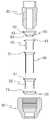
상기와 같이 냉매 관의 각 끝단 부분과 실내/외기 간의 기밀성이 유지되게 설치하는 종래의 구조는, 도 1에 나타낸 바와 같은 한국등록특허 10-1561257호가 있으며, 그 구성은, 에어컨디셔너의 실내/외기 해당 개소에 설치되는 밸브(20)와, 전방에 나팔모양의 확관부(31)가 형성된 냉매 관(30)과, 상기 확관부의 내측에 끼워 결합되는 내부확관부(41)가 형성된 내부슬리브(40)와, 상기 확관부의 외측과 결합되는 외부확관부(51)가 형성된 외부슬리브(50)와, 확관부, 내부슬리브, 외부슬리브를 수용한 상태에서 상기 밸브(20)와 나사 결합되는 너트(30)로 이루어진 냉매 관의 연결구조에 있어서,A conventional structure in which the airtightness between each end portion of the refrigerant tube and the indoor / outdoor air is maintained is as described in Korean Patent No. 10-1561257 as shown in FIG. 1, A
상기 밸브(20)의 하부와 내부확관부(41)의 사이에는 기밀성을 확보함과 동시에 상기 내부확관부를 보호하도록 내부확관부와 부합하는 형상의 제1실링부재(60)가 개제되고, 그 제1실링부재는 내측 면이 상기 밸브의 하부와 긴밀히 면 접촉되고, 외측 면은 상기 내부확관부와 긴밀히 면 접촉되는 확장부(61)와, 그 확장부 하부에 형성되어 상기 내부슬리브(40)에 긴밀히 끼워 결합되는 하부슬리브(63)와, 상기 확장부의 상부에 수직 상향하도록 형성되어 상단이 상기 밸브의 하부와 접촉되는 상부연장부(62)로 이루어지고,A first sealing member (60) is formed between the lower portion of the valve (20) and the inner tube portion (41) to secure airtightness and protect the inner tube portion The first sealing member includes an
상기 너트(30)의 내부와 외부확관부(51)의 사이에는 기밀성을 확보함과 동시에 외부확관부를 보호하도록 외부확관부와 부합하는 형상의 제2실링부재(70)가 개제되고, 그 제2실링부재의 상부에는 상단이 상기 제1실링부재의 확장부와 접촉되는 수직 상향하는 연장부(71)를 형성시켜 된 것으로 이루어진다.A
상기와 같은 구성의 종래 냉매 관의 연결구조 구성품이 너무 많아 시공성이 떨어짐은 물론, 원가상승의 원인이 되어 제조원가 낮춰야 하는 시대 흐름에 역행하는 문제점과 아울러 냉매 관(30)의 끝 부분을 나팔모양으로 확관해야 하기 때문에 그 확관부가 취약해지는 문제점이 발생하였다.The connection structure of the conventional refrigerant pipe having the above-described structure is so numerous that not only the workability of the refrigerant pipe is reduced, but also the cost of the refrigerant pipe is raised and the manufacturing cost is lowered. In addition, the end of the
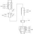
또한, 근래에 제공된 공기 조화기용 배관장치는 도 2에 나타낸 바와 같은 한국공개특허 10-2017-0124178호가 있으며, 그 구성은, 알루미늄 합금으로 이루어진 선단부가 확관된 제1배관(P1)과, 상기 제1배관의 일단부 외주를 둘러싸도록 배치되며 링 형상으로 구성되고 상기 제1배관의 외주면에 슬라이딩 가능하게 끼워진 연결 블록(11)과, 상기 연결 블록의 후단부에 배치되고 상기 제1배관의 외주 면에 끼워진 제1패킹 부재(12)와, 상기 제1배관과 동축 상에 배치된 제2배관(P2)과, 상기 제2배관의 일단부에 결합되고 외주면에 수나사부(13)가 구비된 니플 부재(14)와, 상기 니플 부재의 선단부와 상기 제1배관이 마주하는 부위에 배치된 제2패킹 부재(80) 및 상기 제2패킹 부재를 사이에 두고 상기 니플 부재와 상기 연결 블록을 결합하도록 상기 연결 블록을 수용하여 상기 니플 부재에 나사 결합된 너트 부재(60)를 포함하며, 상기 너트 부재는 상기 연결 블록과 나사 결합되는 과정에서 상기 제1배관의 선단부를 소성 변형시킴으로써 상기 연결 블록이 상기 제1배관으로부터 이탈되지 않도록 된 것으로 이루어진다.In addition, a piping apparatus for an air conditioner provided recently is disclosed in Korean Patent Laid-open Publication No. 10-2017-0124178 as shown in Fig. 2, and its constitution is composed of a first piping P1 in which a front end made of an aluminum alloy is expanded, A connecting block (11) arranged to surround the outer periphery of one end of the first pipe and formed in a ring shape and slidably fitted on an outer circumferential surface of the first pipe, and a connecting block (11) disposed at the rear end of the connecting block A second pipe (P2) disposed coaxially with the first pipe, and a second pipe (12) coupled to one end of the second pipe and having a male threaded portion (13) on an outer peripheral surface thereof, (14), a second packing member (80) disposed at a portion where the tip of the nipple member faces the first pipe, and a second packing member By accepting the connection block, And a nut member (60) screwed to the nipple member, wherein the nut member plastically deforms the tip of the first pipe in the process of screwing the nut member to the connection block, so that the connection block is not separated from the first pipe .
상기와 같은 구성의 종래 공기 조화기용 배관장치 역시도 구성품이 너무 많아 시공성이 떨어짐은 물론, 원가상승의 원인이 되어 제조원가 낮춰야 하는 시대 흐름에 역행하는 문제점과 아울러 배관의 끝 부분을 나팔모양으로 확관해야 하기 때문에 그 확관부가 취약해지는 문제점이 발생하였다.The conventional piping system for the air conditioner having the above-described structure also has a problem that the piping system has a problem that the piping system has a large number of components, Therefore, there is a problem that the expansion part becomes weak.
본 발명은 상기와 같은 문제점을 해소하고자 발명된 것으로 그 목적은,The present invention has been made to solve the above-mentioned problems,
첫째, 냉매 관의 연결구조 구성을 간소화하여 시공성은 물론 제조원가를 절감할 수 있도록 하고,First, the structure of the connection structure of the refrigerant pipe is simplified to reduce the manufacturing cost as well as the workability,
둘째, 냉매 관의 연결부 즉 끝 부분을 확관하지 않고 그대로 사용하면서도 기밀성이 확보되게 하며,Second, airtightness is ensured while the connecting portion or the end portion of the refrigerant tube is used without being expanded,
셋째, 냉매 관의 연결부가 결속도중 변형되거나 훼손되지 않고 원형 그대로 유지되어 사용수명을 연장할 수 있도록 한 냉매 관의 연결구조를 제공함에 있다.Third, the connection structure of the refrigerant pipe is provided in which the connection part of the refrigerant pipe is maintained in a circular shape without being deformed or damaged during the connection, thereby extending service life.
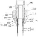
상기한 목적을 달성하기 위한 본 발명에 따른 냉매 관 연결구조의 과제 해결 수단 구성은, 외부 선단부에 경사면(112)이 형성되고 그 경사면 이후에는 숫 나사부(113)가 형성되며 내부 중앙에는 길이방향을 따라 냉매유로(111)를 관통 형성시켜 된 밸브(110); 상기 숫 나사부와 나사결합 되도록 내주 면에 암 나사부(121)가 형성되고 그 암 나사부의 후방에는 공간(123)이 마련하며 상기 공간의 후방에는 입구에 테이퍼부(124)를 형성시켜 상기 공간의 내경보다 작은 내경을 갖는 냉매 관(150)이 끼워 결합되는 냉매 관결합공(122)을 형성시켜 된 너트(120); 상기 냉매 관의 전방 내부에 긴밀히 끼워져 냉매 관이 안쪽으로 수축 변형되는 것을 방지하는 관부(131)가 형성되고 그 관부의 전방에는 냉매 관의 외부로 노출되어 냉매의 누기를 방지하는 확장부(132)를 형성시켜 된 슬리브(130); 상기 밸브의 선단부와 너트의 내부 사이 공간에 개재되어 볼트의 숫 나사부를 따라 너트가 조여지면서 볼트와 너트 사이의 기밀성이 확보되어 냉매의 누기를 방지해주는 씰링부재(140)를 형성시되, 그 씰링부재(140)는 내측 면이 상기 경사면의 경사각과 준하는 각을 갖도록 형성되어 경사면과 긴밀히 접촉되게 형성되고 상면은 상기 90°절곡된 확장부(132)의 저면과 접촉되게 형성되며 외측면은 너트의 내면과 접촉되게 형성된 동(Cu), 알루미늄(Al), 스테인레스(stainless) 중 어느 하나의 재질로 형성된 3각형의 링(143)과, 일측단면(144a)은 상기 90°절곡된 확장부(132)와 동일한 각을 갖도록 형성되어 확장부와 긴밀히 접촉되고 타측단면(144b)은 상기 테이퍼부와 준하는 테이퍼 각을 갖도록 형성되어 테이퍼부와 긴밀히 접촉되도록 형성된 내부가 중공인 원통형의 탄성체(144)로 이루어진다.According to an aspect of the present invention, there is provided a refrigerant pipe connection structure, comprising: an inclined surface formed on an outer end portion of the refrigerant pipe; a male screw portion formed on an inclined surface thereof; A
상기와 같은 구성의 본 발명에 따른 냉매 관 연결구조는, 구성을 간소화하여 시공성을 향상시킴은 물론 제조원가를 절감하고, 또 냉매 관의 연결부 즉 끝 부분을 확관하지 않고 그대로 사용하면서도 기밀성이 확보되게 하며, 냉매 관의 연결부가 결속도중 변형되거나 훼손되지 않고 원형 그대로 유지되어 사용수명을 연장할 수 있는 효과가 있다.The refrigerant pipe connection structure according to the present invention having the above-described structure can simplify the construction to improve the workability, reduce the manufacturing cost, and secure the airtightness while using the connection portion or end portion of the refrigerant pipe without enlarging And the connection part of the refrigerant pipe is kept in a circular shape without being deformed or damaged in the jointing degree, thereby extending service life.
도 1은 종래 냉매 관의 연결구조의 분해 단면도,
도 2는 종래 공기 조화기용 배관장치의 결합 단면도,
도 3은 본 발명 제1실시 예의 분해 단면도,
도 4는 본 발명 제1실시 예의 결합 단면도,
도 5는 본 발명 제1실시 예의 씰링부재 구조를 설명하기 위한 일부 발췌 단면 사시도,
도 6은 본 발명 제2실시 예의 분해 단면도,
도 7은 본 발명 제2실시 예의 결합 단면도,
도 8은 본 발명 제2실시 예의 누기방지수단 구조를 설명하기 위한 일부를 발췌 단면한 사시도,1 is an exploded cross-sectional view of a connection structure of a conventional refrigerant pipe,
FIG. 2 is an assembled cross-sectional view of a conventional piping system for an air conditioner,
3 is an exploded sectional view of the first embodiment of the present invention,
4 is an assembled cross-sectional view of the first embodiment of the present invention,
5 is a partially cutaway perspective view for explaining the sealing member structure of the first embodiment of the present invention,
6 is an exploded sectional view of a second embodiment of the present invention,
FIG. 7 is an assembled cross-sectional view of a second embodiment of the present invention,
FIG. 8 is a perspective view showing a part of a second embodiment of the present invention,
본 발명에 따른 냉매 관 연결구조를 첨부도면을 참조하여 상세하게 설명하면 다음과 같다.The refrigerant pipe connection structure according to the present invention will be described in detail with reference to the accompanying drawings.
본 발명은 도 3에 나타낸 바와 같이 외부 선단부에 경사면(112)이 형성되고 그 경사면(112) 이후에는 숫 나사부(113)가 형성되며 내부 중앙에는 길이방향을 따라 냉매유로(111)를 관통 형성시켜 된 밸브(110)가 마련되는데, 이와 같은 밸브(100)의 구성은 일반적인 것으로 그에 대한 구체적인 설명은 생략한다.3, an
그리고 상기 밸브(110)에서 외부 선단부에 형성된 경사면(112)의 기울기 각도는 45±5°로 함이 바람직하다. 그 이유는 상기 경사면(112)의 기울기 각도가 가장 안정적인 각도 임은 물론, 가공이 용이하기 때문이다.The inclination angle of the
또 상기 숫 나사부(113)와 나사결합 되도록 내주 면에 암 나사부(121)가 형성되고 그 암 나사부(121)의 내부 후방에는 공간(123)이 마련하며 상기 공간(123)의 후방에는 입구의 테이퍼부(124)와 연이어지며 상기 공간(123)의 내경보다 작은 내경을 갖는 냉매 관(150)이 끼워 결합되는 냉매 관 결합공(122)을 형성시켜 된 너트(120)가 마련된다.A
상기 냉매 관 결합공(122)과 암 나사부(121)의 사이에 공간(13)을 형성시킨 이유는, 도 4에 나타낸 바와 같이 상기 냉매 관 결합공(122)으로 냉매 관(150)을 결합하고 밸브(110)의 숫 나사부(113)와 결합 된 너트(120)를 조여 결합력을 강하게 할 때에 상기 공간(123)에 구비된 씰링부재(140)가 압축되면서 밸브(100)와 너트(120) 간의 기밀성을 유지하도록 하기 위함이다.The reason why the
또한, 본 발명은 도 3에 나타낸 바와 같이 상기 냉매 관(150)의 전방 내부에 긴밀히 끼워져 냉매 관(150)이 안쪽으로 수축 변형되는 것을 방지하는 관부(131)가 형성되고, 그 관부(131)의 전방에는 냉매 관(150)의 외부로 노출되어 냉매의 누기를 방지하는 확장부(132)를 형성시켜 된 슬리브(130)가 마련된다.3, a
상기와 같은 구성의 슬리브(130)에서 확장부(132)를 형성시킨 이유는, 도 4 나타낸 바와 같이 상기 확장부(132)가 밸브(110)의 경사면(112)을 감싸며 긴밀히 결합됨으로 슬리브(130)의 유동을 방지함은 물론, 밸브(100)와 너트(120) 간의 기밀성을 1차로 확보시켜 주기 위함이다.The reason for forming the
상기 슬리브(130)의 재질은 상기 냉매 관(150)보다 강한 재질의 것을 사용하여 냉매 관(150)의 변형을 방지하도록 함이 바람직한데, 그 일실시 예의 재질은 스테인레스이다.Preferably, the
또 상기 관부(131)를 냉매 관(150)의 입구 내부에 긴밀히 삽입하는 이유는, 냉매 관(150)의 단부가 확장되지 않고 냉매 관(150)의 직경 그대로를 유지하고 있기 때문에 숫 나사부(113)에 결합된 너트(120)를 조이게 되면 씰링부재(140)가 압축되면서 냉매 관(150)에 압력을 가해지고 그에 따라 상기 냉매 관(150)의 직경 그대로를 유지하고 냉매 관(150)의 단부가 안쪽으로 찌그러지는 등을 변형이 발생하여 기밀성 확보가 어려지는 문제점이 발생한다.The reason why the
따라서 본 발명에서는 상기의 냉매 관(150) 단부 변형을 방지함과 동시에 밸브(110)의 냉매유로(111)를 통하여 슬리브(130)의 관부(131)로 진행하는 냉매의 흐름이 누기되지 않고 원활하게 진행하도록 하기 위함이다.Accordingly, in the present invention, the end of the
또한, 상기 슬리브(130)의 일실시 예로써, 상기 확장부(132)는 상기 경사면(112)의 경사 각과 준하는 경사면을 갖는 나팔관 형태로 형성되는데, 그 이유는, 밸브(110)의 경사면(112)을 수용하며 긴밀히 감싸고 보호하여 기밀성을 확보하도록 하기 위함이다.The
상기와 같은 슬리브(130)의 재질은 스테인레스로 함이 바람직하나 필요에 따라서는 동(Cu)재질의 것을 사용해도 무방하다.The
그리고 상기 너트(120)에서 테이퍼부(124)의 각은 상기 확장부(132)의 경사면 각보다 작게 형성되는데, 그 이유는, 너트(120)를 더욱 강하게 조여 결합할 때에 너트(120)의 조임력이 강해질수록 테이퍼부(124)가 씰링부재(140)의 타측단부(142)를 냉매 관(150) 쪽으로 더욱 강하게 압력을 가하여 기밀성을 확보하도록 하기 위함이다.The angle of the
또 상기 확장부(132)의 경사면 각을 테이퍼부(124)의 각보다 크게 한 이유는, 상기와 같이 너트(120)의 조임력이 강해질수록 확장부(132)가 씰링부재(140)의 일측단부(141)를 냉매 관(150) 쪽으로 더욱 강하게 압력을 가하여 기밀성을 확보하도록 하기 위함이다.The reason why the inclined surface angle of the
상기 씰링부재(140)는 내부가 중공인 원통형의 탄성체로써, 일측단부(141)는 상기 확장부(132)와 준하는 각을 유지하도록 형성되어 확장부(132)와 긴밀히 접촉되고, 타측단부(142)는 상기 테이퍼부(124)와 준하는 테이퍼 각을 유지하도록 형성되어 테이퍼부(124)와 긴밀히 접촉되도록 형성시키는데, 그 이유는, 확장부(132)는 씰링부재(140)의 일측단부(141)와 긴밀히 접촉되어 기밀성을 유지하고, 테이퍼부(124)는 씰링부재(140)의 타측단부(142)와 긴밀히 접촉되어 기밀성을 유지하도록 하기 위함이다.The sealing
그리고 상기 확장부(132)의 길이(l)는 도 3에 나타낸 바와 같이 상기 경사면의 길이(L)보다 길지 않게 형성되는데, 그 이유는, 상기 확장부(132)의 길이(l)가 경사면(112)의 길이(L)보다 길게되면 너트(120)를 조여 강하게 결합하였을 때 확장부(132)의 선단이 경사면(112)의 후단으로 돌출되게 노출됨으로 그에 따른 결합력이 약해지고 그 결합력의 약함으로 인하여 기밀성이 확보되지 못하는 문제점이 발생함으로 확장부(132)의 길이(l)는 상기 경사면의 길이(L)보다 길지 않아야 하는 것이다.The length l of the
본 발명의 또 다른 실시 예로는 상기 확장부(132)는 도 6에 나타낸 바와 같이 관부(131)로부터 외측으로 90°유지되게 절곡되고, 그 확장부(132)의 폭(W)은 경사면의 두께(T))보다 넓지 않게 형성되는데, 그 이유는 상기 확장부(132)의 폭(W)이 경사면(112)의 두께(T)보다 넓게 되면 너트(120)의 내주 면에 확장부(132)의 끝단부가 결려 결합력이 약해지고 그 결합력의 약함으로 인하여 기밀성이 확보되지 못하는 문제점이 발생함으로 확장부(132)의 폭(W)은 경사면의 두께(T))보다 넓지 않아야 한다.6, the
또 상기 씰링부재(140)의 다른 실시 예는 도 6 및 도 7에 나타낸 바와 같이 내측 면이 상기 경사면(112)의 경사각과 준하는 각을 갖도록 형성되어 상기 경사면(112)과 긴밀히 접촉되게 형성되고, 상면은 상기 90°절곡된 확장부(132)의 저면과 접촉되게 형성되며, 외측 면은 너트(120)의 내면과 접촉되게 형성된 동(Cu), 알루미늄(Al), 스테인레스(stainless) 중 어느 하나의 재질로 형성된 3각형의 링(143)과, 일측단면(144a)은 상기 90°절곡된 확장부(132)와 동일한 각을 갖도록 형성되어 확장부(132)와 긴밀히 접촉되고 타측단면(144b)은 상기 테이퍼부(124)와 준하는 테이퍼 각을 갖도록 형성되어 테이퍼부(124)와 긴밀히 접촉되도록 형성된 내부가 중공인 원통형의 탄성체(144)로 이루어진다.6 and 7, the inner surface of the sealing
상기 씰링부재(140)에서 슬리브(130)의 확장부(132)를 기준으로 일측에는 상기 밸브(110)의 경사면(112)을 감싸는 3각형의 링(143)이 마련되고, 타측에는 내부가 중공인 원통형의 탄성체(144)가 공간(123)에 마련되는데, 그 이유는, 기밀성을 더욱 강하게 유지시키기 위함이다.A
상기와 같은 구성에서 너트(120)를 강하게 조이게 되면 테이퍼부(124)가 탄성체(144)의 타측단면(144b)에 강한 압력을 가하면서 탄성체(144)가 냉매 관(150)의 외부와 견고히 밀착되어 기밀성이 확보되고, 그와 동시에 3각형의 링(143)도 밸브(110)의 경사면(112)과 견고히 밀착되어 기밀성이 확보되는 것이다.When the
따라서 상기의 씰링부재(140)는 밸브(110)의 경사면(112)과 3각형의 링(143)이 1차 기밀성을 유지하고, 또 슬리브(130)의 90°절곡된 확장부(132)가 2차 기밀성을 유지하며, 탄성체(144)가 3차 기밀성을 유지시킴으로 냉매의 누기를 완전하게 차단하는 것이다.The sealing
상기의 탄성체(140) 재질은 고무 또는 실리콘 등 누름 압력을 받으면 수축되고 누름 압력이 해제되면 수축되어 있던 것이 복원되는 기밀성을 유지할 수 있는 것이면 모두 가능하다.The material of the
상기 냉매 관(150)은 동관이나 알루미늄관 중 어느 것을 선택하여 사용해도 무방하나 바람직하게는 원가가 절감되는 알루미늄관의 외부 표면에 부식을 방지하고 보온성을 높이기 하여 수지 코팅한 것을 사용함이 좋다.The
이상에서 설명한 바와 같은 본 발명의 냉매 관 연결구조는, 구성을 간소화하여 시공성을 향상시킴은 물론 제조원가를 절감하고, 또 냉매 관의 연결부 즉 끝 부분을 확관하지 않고 그대로 사용하면서도 기밀성이 확보되게 하며, 냉매 관의 연결부가 결속도중 변형되거나 훼손되지 않고 원형 그대로 유지되어 사용수명을 연장할 수 있는 장점이 있는 것이다.The refrigerant pipe connection structure of the present invention as described above can simplify the construction to improve the workability and reduce the manufacturing cost and secure the airtightness while using the connection portion or the end portion of the refrigerant pipe as it is, The connection portion of the refrigerant pipe is maintained in a circular shape without being deformed or damaged during the connection, thereby extending service life.
110 : 밸브 111 : 냉매유로
112 : 경사면 113 : 숫 나사부
120 : 너트 121 : 암 나사부
122 : 냉매 관결합공 123 : 공간
124 : 테이퍼부 130 : 슬리브
131 : 관부 132 : 확장부
140 : 씰링부재 141 : 일측단부
142 : 타측단부 143 : 3각형의 링
144 : 탄성체 144a : 일측단면
144b : 타측단면 150 : 냉매 관
151 : 알루미늄관 152 : 수지코팅층
L : 경사면의 길이 l : 확장 부의 길이
T : 경사면의 두께 W : 확장부의 폭110: valve 111: refrigerant passage
112: inclined surface 113: male threads
120: Nut 121: Female thread
122: Refrigerant pipe joint ball 123: Space
124: tapered portion 130: sleeve
131: tube portion 132:
140: sealing member 141: one end
142: the other end 143: a triangular ring
144:
144b: the other end surface 150: refrigerant tube
151: aluminum tube 152: resin coating layer
L: length of the inclined surface l: length of the extension part
T: thickness of the inclined surface W: width of the expanded portion
Claims (7)
Translated fromKorean상기 숫 나사부와 나사결합 되도록 내주 면에 암 나사부(121)가 형성되고 그 암 나사부의 후방에는 공간(123)이 마련하며 상기 공간의 후방에는 입구에 테이퍼부(124)를 형성시켜 상기 공간의 내경보다 작은 내경을 갖는 냉매 관(150)이 끼워 결합되는 냉매 관결합공(122)을 형성시켜 된 너트(120);
상기 냉매 관의 전방 내부에 긴밀히 끼워져 냉매 관이 안쪽으로 수축 변형되는 것을 방지하는 관부(131)가 형성되고 그 관부의 전방에는 냉매 관의 외부로 노출되어 냉매의 누기를 방지하는 확장부(132)를 형성시켜 된 슬리브(130);
상기 밸브의 선단부와 너트의 내부 사이 공간에 개재되어 볼트의 숫 나사부를 따라 너트가 조여지면서 볼트와 너트 사이의 기밀성이 확보되어 냉매의 누기를 방지해주는 씰링부재(140)를 형성시되, 그 씰링부재(140)는 내측 면이 상기 경사면의 경사각과 준하는 각을 갖도록 형성되어 경사면과 긴밀히 접촉되게 형성되고 상면은 상기 90°절곡된 확장부(132)의 저면과 접촉되게 형성되며 외측면은 너트의 내면과 접촉되게 형성된 동(Cu), 알루미늄(Al), 스테인레스(stainless) 중 어느 하나의 재질로 형성된 3각형의 링(143)과, 일측단면(144a)은 상기 90°절곡된 확장부(132)와 동일한 각을 갖도록 형성되어 확장부와 긴밀히 접촉되고 타측단면(144b)은 상기 테이퍼부와 준하는 테이퍼 각을 갖도록 형성되어 테이퍼부와 긴밀히 접촉되도록 형성된 내부가 중공인 원통형의 탄성체(144)로 형성된 것을 특징으로 하는 냉매 관의 연결구조.A valve 110 having an inclined surface 112 formed at an outer end portion thereof and a male threaded portion 113 formed at an inclined surface thereof and having a refrigerant passage 111 formed in a longitudinal direction thereof at an inner center thereof;
A female screw portion 121 is formed on the inner circumferential surface to be screwed with the male screw portion and a space 123 is provided at the rear of the female screw portion and a tapered portion 124 is formed at the entrance of the space, A nut 120 formed with a coolant pipe coupling hole 122 into which a coolant pipe 150 having a smaller inner diameter is fitted;
A tube portion 131 is formed in the front of the refrigerant tube so as to prevent the refrigerant tube from being shrunk and deformed inward, and an extension portion 132 for preventing the refrigerant from leaking outwardly from the refrigerant tube is disposed in front of the tube portion. A sleeve 130 formed on the outer circumferential surface thereof;
A sealing member 140 interposed in a space between the tip end of the valve and the inside of the nut to secure the airtightness between the bolt and the nut to tighten the nut along the male screw portion of the bolt to prevent the refrigerant from leaking, The inner surface of the nut 140 is formed to have an angle equal to the angle of inclination of the inclined surface so as to be in intimate contact with the inclined surface and the upper surface thereof is formed to be in contact with the bottom surface of the 90 ° bent extension portion 132, A triangular ring 143 formed of any one of copper (Cu), aluminum (Al), and stainless steel that is formed to be in contact with the side surface 144a, And the other end face 144b is formed to have a taper angle that is the same as that of the tapered portion. The other end face 144b is formed in a hollow cylindrical shape Connection structure of a refrigerant pipe, characterized in that formed from a magnetic material (144).
상기 확장부(132)는 상기 경사면(112)의 경사 각과 준하는 경사면을 갖는 나팔관 형태로 형성되고, 상기 테이퍼부(124)의 각은 상기 확장부(132)의 경사면 각보다 작게 형성된 것을 특징으로 하는 냉매 관의 연결구조.The method according to claim 1,
The extension part 132 is formed in a trumpet shape having an inclined surface corresponding to the inclination angle of the inclined surface 112 and the angle of the tapered part 124 is smaller than the inclination angle of the extension part 132 Connection structure of refrigerant tube.
상기 씰링부재(140)는 내부가 중공인 원통형의 탄성체로써, 일측단부(141)는 상기 확장부(132)와 준하는 각을 유지하도록 형성되어 확장부와 긴밀히 접촉되고, 타측단부(142)는 상기 테이퍼부(124)와 준하는 테이퍼 각을 유지하도록 형성되어 테이퍼부와 긴밀히 접촉되도록 형성된 것을 특징으로 하는 냉매 관의 연결구조.The method according to claim 1 or 2,
The sealing member 140 is a cylindrical elastic body having an inner hollow portion and one end portion 141 is formed so as to maintain an angle similar to that of the extending portion 132 and is in intimate contact with the extending portion, Wherein the tapered portion is formed so as to maintain a taper angle similar to that of the tapered portion, and is formed to be in intimate contact with the tapered portion.
상기 확장부(132)의 길이(l)는 상기 경사면의 길이(L)보다 길지 않게 형성된 것을 특징으로 냉매 관의 연결구조.3. The method of claim 2,
And the length (1) of the extension part (132) is not longer than the length (L) of the inclined surface.
상기 확장부(132)는 관부로부터 외측으로 90°유지되게 절곡되고, 그 확장부의 폭(W)은 경사면의 두께(T))보다 넓지 않게 형성된 것을 특징으로 하는 냉매 관의 연결구조.The method according to claim 1,
Wherein the expansion part (132) is bent to be held at an angle of 90 占 outward from the tube part, and the width (W) of the expansion part is not wider than the thickness (T) of the inclined surface).
상기 냉매 관(150)은 알루미늄관(151)의 외부 표면에 수지 코팅하여 수지코팅층(152)을 형성한 것을 특징으로 하는 냉매 관의 연결구조.The method according to claim 1,
Wherein the refrigerant pipe (150) is resin coated on an outer surface of the aluminum pipe (151) to form a resin coating layer (152).
Priority Applications (2)
| Application Number | Priority Date | Filing Date | Title |
|---|---|---|---|
| KR1020180046808AKR101879248B1 (en) | 2018-04-23 | 2018-04-23 | Connecting structure of refrigerant pipe |
| CN201810996188.8ACN110388522A (en) | 2018-04-23 | 2018-08-29 | The connection structure of refrigerant pipe |
Applications Claiming Priority (1)
| Application Number | Priority Date | Filing Date | Title |
|---|---|---|---|
| KR1020180046808AKR101879248B1 (en) | 2018-04-23 | 2018-04-23 | Connecting structure of refrigerant pipe |
Publications (1)
| Publication Number | Publication Date |
|---|---|
| KR101879248B1true KR101879248B1 (en) | 2018-07-17 |
Family
ID=63048847
Family Applications (1)
| Application Number | Title | Priority Date | Filing Date |
|---|---|---|---|
| KR1020180046808AActiveKR101879248B1 (en) | 2018-04-23 | 2018-04-23 | Connecting structure of refrigerant pipe |
Country Status (2)
| Country | Link |
|---|---|
| KR (1) | KR101879248B1 (en) |
| CN (1) | CN110388522A (en) |
Cited By (6)
| Publication number | Priority date | Publication date | Assignee | Title |
|---|---|---|---|---|
| KR101949436B1 (en) | 2018-08-27 | 2019-03-04 | 오형동 | Connecting structure of refrigerant pipe |
| KR20210046307A (en)* | 2019-10-18 | 2021-04-28 | 유학현 | Ferrule assembly for fitting |
| CN113227627A (en)* | 2019-02-15 | 2021-08-06 | 大金工业株式会社 | Joint member and unit for air conditioner |
| KR20220001905U (en) | 2021-01-27 | 2022-08-03 | 오형동 | Gasket for Refrigerant tube connection sealing |
| CN116989196A (en)* | 2022-04-26 | 2023-11-03 | 宁波奥克斯电气股份有限公司 | Joint structure of air conditioner connecting pipe and air conditioner |
| US20230383888A1 (en)* | 2020-10-20 | 2023-11-30 | Chongqing Haier Refrigeration Electric Appliance Co., Ltd. | Noise reduction device and refrigeration device having the same |
Families Citing this family (4)
| Publication number | Priority date | Publication date | Assignee | Title |
|---|---|---|---|---|
| CN111928544A (en)* | 2020-08-28 | 2020-11-13 | 格力电器(芜湖)有限公司 | Solderless shunts, refrigeration systems and air conditioners |
| WO2022110714A1 (en)* | 2020-11-27 | 2022-06-02 | 广东美的制冷设备有限公司 | Air conditioner |
| CN114543195A (en)* | 2020-11-27 | 2022-05-27 | 广东美的制冷设备有限公司 | Air conditioner |
| CN112797509B (en)* | 2021-01-11 | 2022-11-04 | 上海宝派餐饮管理有限公司 | Gas type central air conditioner |
Citations (4)
| Publication number | Priority date | Publication date | Assignee | Title |
|---|---|---|---|---|
| JP2013224677A (en)* | 2012-04-19 | 2013-10-31 | Nippon Soken Inc | Pipe joint |
| KR101561257B1 (en) | 2014-07-21 | 2015-10-16 | 오형동 | Connecting structure of refrigerant pipe |
| JP2016020727A (en)* | 2014-07-15 | 2016-02-04 | 井上スダレ株式会社 | Pipe joint structure for refrigerant |
| KR20170124178A (en) | 2016-05-02 | 2017-11-10 | 주식회사 튜바시스코리아 | Pipe connection structure air conditioning system |
Family Cites Families (6)
| Publication number | Priority date | Publication date | Assignee | Title |
|---|---|---|---|---|
| KR200346950Y1 (en)* | 2004-01-16 | 2004-04-08 | 김용근 | Apparatus for connecting pipe |
| DE202004008210U1 (en)* | 2004-05-18 | 2004-09-02 | Breidenbach, Wolfgang | Sealing ring for pipes connected by union nut, especially siphon, comprises rigid base ring, to which flexible seal with triangular cross-section is fixed, components being e.g. glued together along surfaces in contact |
| KR101055938B1 (en)* | 2011-03-28 | 2011-08-09 | 성기천 | Connecting device of aluminum coated pipe with expansion pipe at its end and connecting method using the same |
| KR101397531B1 (en)* | 2012-01-27 | 2014-05-20 | 박애경 | Pipe connection structure for air conditioning system |
| KR20140111862A (en)* | 2013-03-12 | 2014-09-22 | 박애경 | Pipe connection structure for air conditioning system |
| CN103604013B (en)* | 2013-05-05 | 2015-12-09 | 孙海潮 | A kind of connecting pipe fitting for pipeline |
- 2018
- 2018-04-23KRKR1020180046808Apatent/KR101879248B1/enactiveActive
- 2018-08-29CNCN201810996188.8Apatent/CN110388522A/enactivePending
Patent Citations (4)
| Publication number | Priority date | Publication date | Assignee | Title |
|---|---|---|---|---|
| JP2013224677A (en)* | 2012-04-19 | 2013-10-31 | Nippon Soken Inc | Pipe joint |
| JP2016020727A (en)* | 2014-07-15 | 2016-02-04 | 井上スダレ株式会社 | Pipe joint structure for refrigerant |
| KR101561257B1 (en) | 2014-07-21 | 2015-10-16 | 오형동 | Connecting structure of refrigerant pipe |
| KR20170124178A (en) | 2016-05-02 | 2017-11-10 | 주식회사 튜바시스코리아 | Pipe connection structure air conditioning system |
Cited By (9)
| Publication number | Priority date | Publication date | Assignee | Title |
|---|---|---|---|---|
| KR101949436B1 (en) | 2018-08-27 | 2019-03-04 | 오형동 | Connecting structure of refrigerant pipe |
| CN110864168A (en)* | 2018-08-27 | 2020-03-06 | 吴炯东 | Refrigerant pipe connection structure |
| CN113227627A (en)* | 2019-02-15 | 2021-08-06 | 大金工业株式会社 | Joint member and unit for air conditioner |
| KR20210046307A (en)* | 2019-10-18 | 2021-04-28 | 유학현 | Ferrule assembly for fitting |
| KR102291871B1 (en)* | 2019-10-18 | 2021-08-19 | 유학현 | Ferrule assembly for fitting |
| US20230383888A1 (en)* | 2020-10-20 | 2023-11-30 | Chongqing Haier Refrigeration Electric Appliance Co., Ltd. | Noise reduction device and refrigeration device having the same |
| EP4206563A4 (en)* | 2020-10-20 | 2024-03-20 | Chongqing Haier Refrigeration Electric Appliance Co., Ltd. | NOISE REDUCTION DEVICE AND COOLING DEVICE THEREFROM |
| KR20220001905U (en) | 2021-01-27 | 2022-08-03 | 오형동 | Gasket for Refrigerant tube connection sealing |
| CN116989196A (en)* | 2022-04-26 | 2023-11-03 | 宁波奥克斯电气股份有限公司 | Joint structure of air conditioner connecting pipe and air conditioner |
Also Published As
| Publication number | Publication date |
|---|---|
| CN110388522A (en) | 2019-10-29 |
Similar Documents
| Publication | Publication Date | Title |
|---|---|---|
| KR101879248B1 (en) | Connecting structure of refrigerant pipe | |
| KR101195425B1 (en) | Connecting structure of refrigerant pipe | |
| JPS6184492A (en) | Adapter sealing body | |
| US20090261573A1 (en) | Pipe joint | |
| KR20080080179A (en) | Bite type pipe connection structure, pipe joint, valve, closing valve, refrigeration cycle device, hot water supply device, bite pipe connection method and local pipe connection method | |
| JPH02278094A (en) | Cantilever lip conduit coupling member and assembly thereof | |
| US20080048440A1 (en) | Direct port connection for tubes | |
| KR102158368B1 (en) | refrigerant pipe connector for air conditioner of outdoor fan | |
| JP2006518833A (en) | Adjustable port end with straight thread | |
| KR101889960B1 (en) | Connecting structure of refrigerant pipe | |
| KR20200028589A (en) | Apparatus for coupling pipes | |
| JP2018146027A (en) | Bite-type fittings and air conditioning systems | |
| KR101949436B1 (en) | Connecting structure of refrigerant pipe | |
| US20040124386A1 (en) | Lateral reducing valve | |
| JP2005308101A (en) | Valve device | |
| KR20210123468A (en) | a connecting device of refrigerant of air conditioner | |
| JP2007192328A (en) | Joint structure using metal seal member | |
| US20040150227A1 (en) | Pipe fitting comprising a body and a nut | |
| US20210018120A1 (en) | Compression-type fitting for connecting pipes to hydraulic or pneumatic components or for connecting pipes together, particularly for refrigeration systems | |
| JP3073797B2 (en) | Flareless fittings | |
| KR20230000773U (en) | refrigerant pipe connector for air conditioner of outdoor fan | |
| JP6896314B2 (en) | Resin-coated aluminum piping connector for air conditioner outdoor unit | |
| JPH11325340A (en) | Device for connecting flare joint with flareless joint | |
| KR101005637B1 (en) | Piping connection structure of HVAC system and piping connection method provided in HVAC system | |
| JPH06331076A (en) | Connector part using flare nut |
Legal Events
| Date | Code | Title | Description |
|---|---|---|---|
| PA0109 | Patent application | Patent event code:PA01091R01D Comment text:Patent Application Patent event date:20180423 | |
| PA0201 | Request for examination | ||
| PA0302 | Request for accelerated examination | Patent event date:20180424 Patent event code:PA03022R01D Comment text:Request for Accelerated Examination Patent event date:20180423 Patent event code:PA03021R01I Comment text:Patent Application | |
| E902 | Notification of reason for refusal | ||
| PE0902 | Notice of grounds for rejection | Comment text:Notification of reason for refusal Patent event date:20180528 Patent event code:PE09021S01D | |
| E701 | Decision to grant or registration of patent right | ||
| PE0701 | Decision of registration | Patent event code:PE07011S01D Comment text:Decision to Grant Registration Patent event date:20180611 | |
| GRNT | Written decision to grant | ||
| PR0701 | Registration of establishment | Comment text:Registration of Establishment Patent event date:20180711 Patent event code:PR07011E01D | |
| PR1002 | Payment of registration fee | Payment date:20180711 End annual number:3 Start annual number:1 | |
| PG1601 | Publication of registration | ||
| PR1001 | Payment of annual fee | Payment date:20210525 Start annual number:4 End annual number:4 | |
| PR1001 | Payment of annual fee | Payment date:20220525 Start annual number:5 End annual number:5 | |
| PR1001 | Payment of annual fee | Payment date:20230525 Start annual number:6 End annual number:6 | |
| PR1001 | Payment of annual fee | Payment date:20240425 Start annual number:7 End annual number:7 | |
| PR1001 | Payment of annual fee | Payment date:20250526 Start annual number:8 End annual number:8 |