KR101877921B1 - Optic assembly and light source device for endoscope including the same - Google Patents
Optic assembly and light source device for endoscope including the sameDownload PDFInfo
- Publication number
- KR101877921B1 KR101877921B1KR1020170053980AKR20170053980AKR101877921B1KR 101877921 B1KR101877921 B1KR 101877921B1KR 1020170053980 AKR1020170053980 AKR 1020170053980AKR 20170053980 AKR20170053980 AKR 20170053980AKR 101877921 B1KR101877921 B1KR 101877921B1
- Authority
- KR
- South Korea
- Prior art keywords
- light source
- light
- lower case
- upper case
- optical
- Prior art date
- Legal status (The legal status is an assumption and is not a legal conclusion. Google has not performed a legal analysis and makes no representation as to the accuracy of the status listed.)
- Expired - Fee Related
Links
Images


Classifications
- G—PHYSICS
- G02—OPTICS
- G02B—OPTICAL ELEMENTS, SYSTEMS OR APPARATUS
- G02B23/00—Telescopes, e.g. binoculars; Periscopes; Instruments for viewing the inside of hollow bodies; Viewfinders; Optical aiming or sighting devices
- G02B23/24—Instruments or systems for viewing the inside of hollow bodies, e.g. fibrescopes
- G02B23/2407—Optical details
- G02B23/2461—Illumination
- A—HUMAN NECESSITIES
- A61—MEDICAL OR VETERINARY SCIENCE; HYGIENE
- A61B—DIAGNOSIS; SURGERY; IDENTIFICATION
- A61B1/00—Instruments for performing medical examinations of the interior of cavities or tubes of the body by visual or photographical inspection, e.g. endoscopes; Illuminating arrangements therefor
- A61B1/00163—Optical arrangements
- G—PHYSICS
- G02—OPTICS
- G02B—OPTICAL ELEMENTS, SYSTEMS OR APPARATUS
- G02B23/00—Telescopes, e.g. binoculars; Periscopes; Instruments for viewing the inside of hollow bodies; Viewfinders; Optical aiming or sighting devices
- G02B23/24—Instruments or systems for viewing the inside of hollow bodies, e.g. fibrescopes
- A—HUMAN NECESSITIES
- A61—MEDICAL OR VETERINARY SCIENCE; HYGIENE
- A61B—DIAGNOSIS; SURGERY; IDENTIFICATION
- A61B1/00—Instruments for performing medical examinations of the interior of cavities or tubes of the body by visual or photographical inspection, e.g. endoscopes; Illuminating arrangements therefor
- A61B1/06—Instruments for performing medical examinations of the interior of cavities or tubes of the body by visual or photographical inspection, e.g. endoscopes; Illuminating arrangements therefor with illuminating arrangements
- A—HUMAN NECESSITIES
- A61—MEDICAL OR VETERINARY SCIENCE; HYGIENE
- A61B—DIAGNOSIS; SURGERY; IDENTIFICATION
- A61B1/00—Instruments for performing medical examinations of the interior of cavities or tubes of the body by visual or photographical inspection, e.g. endoscopes; Illuminating arrangements therefor
- A61B1/12—Instruments for performing medical examinations of the interior of cavities or tubes of the body by visual or photographical inspection, e.g. endoscopes; Illuminating arrangements therefor with cooling or rinsing arrangements
- G—PHYSICS
- G02—OPTICS
- G02B—OPTICAL ELEMENTS, SYSTEMS OR APPARATUS
- G02B23/00—Telescopes, e.g. binoculars; Periscopes; Instruments for viewing the inside of hollow bodies; Viewfinders; Optical aiming or sighting devices
- G02B23/02—Telescopes, e.g. binoculars; Periscopes; Instruments for viewing the inside of hollow bodies; Viewfinders; Optical aiming or sighting devices involving prisms or mirrors
- G02B23/04—Telescopes, e.g. binoculars; Periscopes; Instruments for viewing the inside of hollow bodies; Viewfinders; Optical aiming or sighting devices involving prisms or mirrors for the purpose of beam splitting or combining, e.g. fitted with eyepieces for more than one observer
- G—PHYSICS
- G02—OPTICS
- G02B—OPTICAL ELEMENTS, SYSTEMS OR APPARATUS
- G02B23/00—Telescopes, e.g. binoculars; Periscopes; Instruments for viewing the inside of hollow bodies; Viewfinders; Optical aiming or sighting devices
- G02B23/24—Instruments or systems for viewing the inside of hollow bodies, e.g. fibrescopes
- G02B23/2407—Optical details
- G02B23/2423—Optical details of the distal end
- G—PHYSICS
- G02—OPTICS
- G02B—OPTICAL ELEMENTS, SYSTEMS OR APPARATUS
- G02B23/00—Telescopes, e.g. binoculars; Periscopes; Instruments for viewing the inside of hollow bodies; Viewfinders; Optical aiming or sighting devices
- G02B23/24—Instruments or systems for viewing the inside of hollow bodies, e.g. fibrescopes
- G02B23/2476—Non-optical details, e.g. housings, mountings, supports
- A—HUMAN NECESSITIES
- A61—MEDICAL OR VETERINARY SCIENCE; HYGIENE
- A61B—DIAGNOSIS; SURGERY; IDENTIFICATION
- A61B1/00—Instruments for performing medical examinations of the interior of cavities or tubes of the body by visual or photographical inspection, e.g. endoscopes; Illuminating arrangements therefor
- A61B1/06—Instruments for performing medical examinations of the interior of cavities or tubes of the body by visual or photographical inspection, e.g. endoscopes; Illuminating arrangements therefor with illuminating arrangements
- A61B1/0661—Endoscope light sources
- A61B1/0669—Endoscope light sources at proximal end of an endoscope
- A—HUMAN NECESSITIES
- A61—MEDICAL OR VETERINARY SCIENCE; HYGIENE
- A61B—DIAGNOSIS; SURGERY; IDENTIFICATION
- A61B1/00—Instruments for performing medical examinations of the interior of cavities or tubes of the body by visual or photographical inspection, e.g. endoscopes; Illuminating arrangements therefor
- A61B1/06—Instruments for performing medical examinations of the interior of cavities or tubes of the body by visual or photographical inspection, e.g. endoscopes; Illuminating arrangements therefor with illuminating arrangements
- A61B1/0661—Endoscope light sources
- A61B1/0684—Endoscope light sources using light emitting diodes [LED]
- G—PHYSICS
- G02—OPTICS
- G02B—OPTICAL ELEMENTS, SYSTEMS OR APPARATUS
- G02B23/00—Telescopes, e.g. binoculars; Periscopes; Instruments for viewing the inside of hollow bodies; Viewfinders; Optical aiming or sighting devices
- G02B23/24—Instruments or systems for viewing the inside of hollow bodies, e.g. fibrescopes
- G02B23/2407—Optical details
- G02B23/2461—Illumination
- G02B23/2469—Illumination using optical fibres
Landscapes
- Physics & Mathematics (AREA)
- Optics & Photonics (AREA)
- Health & Medical Sciences (AREA)
- Life Sciences & Earth Sciences (AREA)
- Astronomy & Astrophysics (AREA)
- General Physics & Mathematics (AREA)
- Surgery (AREA)
- Heart & Thoracic Surgery (AREA)
- General Health & Medical Sciences (AREA)
- Radiology & Medical Imaging (AREA)
- Biophysics (AREA)
- Engineering & Computer Science (AREA)
- Biomedical Technology (AREA)
- Pathology (AREA)
- Molecular Biology (AREA)
- Nuclear Medicine, Radiotherapy & Molecular Imaging (AREA)
- Animal Behavior & Ethology (AREA)
- Medical Informatics (AREA)
- Public Health (AREA)
- Veterinary Medicine (AREA)
- Endoscopes (AREA)
- Instruments For Viewing The Inside Of Hollow Bodies (AREA)
Abstract
Translated fromKoreanDescription
Translated fromKorean본 발명은 광학 어셈블리 및 이를 포함하는 내시경용 광원장치에 관한 것으로서, 보다 상세하게는 제1광원으로부터 조사되는 빛과 상기 제1광원과 다른 방향에서 상기 제2광원으로부터 조사되는 빛이 동일 방향을 향하도록 전환시키는 광학 어셈블리 및 이를 포함하는 내시경용 광원장치에 관한 것이다.The present invention relates to an optical assembly and a light source device for an endoscope including the same, and more particularly, to an optical assembly for an endoscope, And an endoscope light source device including the optical assembly.
내시경은 인체 내부나, 기계 내부 등의 좁은 공간을 영상으로 촬영하여 관찰할 수 있도록 하는 것으로서, 의료 분야뿐 아니라 정밀한 기계의 해체 없이 내부를 관찰할 수 있게 하거나 또는 파이프 내부의 이상 여부 등을 관찰할 수 있게 하는 등 다양한 산업분야에까지 확대 실시되고 있다.The endoscope is used to observe a narrow space such as the inside of a human body or the inside of a machine so that it can be observed. It can be used not only in the medical field, but also to observe the inside without disassembling a precision machine, And so on.
특히 의료분야에 있어서의 내시경은 수술이나 부검과 같은 신체의 개복이나 절개 없이 소형 카메라를 이용하여 인체내부(위, 기관지, 식도, 대내장, 소내장 등)를 관찰하거나 신체의 일부를 관통하여 복강 내부를 관찰하여 그 이상 여부를 확인할 수 있게 한다.In particular, endoscopes in the medical field can be used to observe the inside of the human body (stomach, bronchus, esophagus, large intestine, small intestine, etc.) by using a small camera without the body open or incision such as surgery or autopsy, Observe the inside to check whether it is abnormal.
일반적으로 잘 알려진 기존의 내시경 시스템은, 신체 내부 기관이나 기계 내부 표면을 보기 위해 빛을 조사하는 광원장치와, 이 광원장치에서 조사된 빛이 인체 내부 기관의 표면으로 입사되어 반사되는 광신호를 받아 전기적 신호(영상 신호)로 변환하는 이미지 센서와, 이 영상 신호를 모니터를 통해 관찰할 수 있도록 전자 신호로 변환하는 엔코더를 포함한 카메라 칩 등으로 이루어진 카메라가 내시경의 선단부에 구성된다.BACKGROUND ART [0002] A well-known conventional endoscope system includes a light source device for irradiating light to see the internal organs of the body or the internal surface of a machine, and a light source for receiving light reflected by the light irradiated from the light source device A camera including an image sensor for converting an image signal into an electrical signal (image signal), and a camera chip including an encoder for converting the image signal into an electronic signal so as to be able to observe the image signal through a monitor is configured at the distal end portion of the endoscope.
한편 의료 기술의 발전에 따라 가시광선을 통한 내시경 검사뿐 아니라 근적외선 등을 통한 내시경 검사도 함께 수행되는 경우가 많으나, 종래의 경우 하나의 내시경을 통해서는 동시에 두 종류의 빛을 전달할 수 없어 별도의 검사로 수행할 수밖에 없었다.In accordance with the development of medical technology, endoscopy through visible light as well as endoscopy through near-infrared rays are often performed. However, in the conventional case, two kinds of light can not be transmitted simultaneously through one endoscope, I had to do it.
이는 시술시간이 길어지게 됨은 물론, 시술자의 추가적인 노력 및 추가적인 시술 비용이 요구되며, 피시술자에게도 반복 시술에 따른 고통이 발생하게 되는 문제가 있었다.This increases the length of time required for the operation, as well as additional effort by the operator and additional treatment costs, which also causes the sufferer to suffer from repeated procedures.
따라서 이와 같은 문제점들을 해결하기 위한 방법이 요구된다.
또한, 관련 종래 기술로써, 가시광과 근적외선을 전달하기 위한 복합 광원부를 포함하는 감시림프절의 근적외선 형광검출장치가 한국공개특허 제10-2015-0007679호에 게시되어 있고, 복수개의 코우히어런트(coherent) 및 비코우히어런트(non-coherent) 광원을 입사시키기 위한 광가이드를 포함하는 광역학 치료 및 검출을 위한 장치가 한국공개특허 제10-2010-0066605호에 게시된 바 있다.Therefore, a method for solving such problems is required.
In the related art, a near-infrared fluorescence detection apparatus for a surveillance lymph node including a complex light source section for transmitting visible light and near-infrared light is disclosed in Korean Patent Laid-Open Publication No. 10-2015-0007679, and a plurality of coherent light- And a light guide for introducing a non-coherent light source are disclosed in Korean Patent Laid-Open No. 10-2010-0066605.
본 발명은 상술한 종래 기술의 문제점을 해결하기 위하여 안출된 발명으로서, 하나의 내시경을 통해 복수 종류의 빛을 전달하여 복합적인 검사를 동시에 수행할 수 있도록 하는 광학 어셈블리 및 이를 포함하는 내시경용 광원장치를 제공하기 위한 목적을 가진다.SUMMARY OF THE INVENTION The present invention is conceived to solve the above problems of the prior art, and it is an object of the present invention to provide an optical assembly capable of carrying out multiple examinations simultaneously by transmitting a plurality of kinds of light through one endoscope, and an endoscope light source device For example.
또한, 이를 통해 시술 소요시간 및 시술비용을 감소시키고, 시술자 및 피시술자의 노력 및 고통을 최소화시킬 수 있도록 하기 위한 목적을 가진다.It is also intended to reduce the time required for the operation and the cost of the operation, and to minimize the effort and suffering of the practitioner and the physician.
본 발명의 과제들은 이상에서 언급한 과제들로 제한되지 않으며, 언급되지 않은 또 다른 과제들은 아래의 기재로부터 당업자에게 명확하게 이해될 수 있을 것이다.The problems of the present invention are not limited to the above-mentioned problems, and other problems not mentioned can be clearly understood by those skilled in the art from the following description.
상기한 목적을 달성하기 위하여 위한 본 발명의 일 실시예에 따른 광학 어셈블리는, 제1광원으로부터 조사되는 빛을 통과시키는 제1광로와, 상기 제1광로의 측부에 연통되어 상기 제1광원과 다른 방향에서 제2광원으로부터 조사되는 빛을 상기 제1광로 내로 유입시키는 제2광로가 내측에 형성된 상부 케이스, 상기 상부 케이스와 대응되게 형성되어 상기 상부 케이스와 결합되는 하부 케이스 및 상기 제1광로에 구비되어, 상기 제1광원으로부터 조사된 빛에 대해서는 진행 방향을 유지시키며, 상기 제2광원으로부터 조사된 빛에 대해서는 상기 제1광원으로부터 조사된 빛과 수평하도록 진행 방향으로 변경시키는 빔 스플릿터를 포함한다.According to an aspect of the present invention, there is provided an optical assembly including a first optical path for passing light irradiated from a first light source, a second optical path communicating with a side of the first optical path, A lower case coupled to the upper case and formed to correspond to the upper case, and a lower case coupled to the upper case; and a lower case coupled to the upper case, And a beam splitter which maintains a traveling direction with respect to the light emitted from the first light source and changes the light emitted from the second light source to a traveling direction so as to be horizontal with the light emitted from the first light source .
상기 상부 케이스 및 상부 하부 케이스 각각은, 상기 제1광로의 전단부에 형성된 제1렌즈결합부 및 상기 제1광로의 후단부에 형성된 제2렌즈결합부를 포함하며, 상기 광학 어셈블리는, 상기 제1렌즈결합부에 결합되는 제1렌즈 및 상기 제2렌즈결합부에 결합되는 제2렌즈를 더 포함할 수 있다.Wherein each of the upper case and the upper lower case includes a first lens coupling portion formed at a front end portion of the first optical path and a second lens coupling portion formed at a rear end portion of the first optical path, A first lens coupled to the lens coupling portion, and a second lens coupled to the second lens coupling portion.
또한, 상기 광학 어셈블리는, 상기 제1렌즈결합부의 전방을 차폐하도록 상기 상부 케이스 및 상기 하부 케이스에 결합되는 제1차폐블록 및 상기 제2렌즈결합부의 후방을 차폐하도록 상기 상부 케이스 및 상기 하부 케이스에 결합되는 제2차폐블록을 더 포함할 수 있다.The optical assembly may further include a first shielding block coupled to the upper case and the lower case to shield the front of the first lens engagement portion, and a second shielding block coupled to the upper case and the lower case to shield the rear of the second lens- And a second shielding block coupled to the second shielding block.
상기 상부 케이스 및 상기 하부 케이스에 형성된 상기 제1광로의 내주면에는 상기 빔 스플릿터의 단면 형상에 대응되는 삽입홈이 형성되어, 상기 빔 스플릿터가 상기 삽입홈에 삽입 고정될 수 있다.An insertion groove corresponding to a sectional shape of the beam splitter is formed on an inner circumferential surface of the first optical path formed in the upper case and the lower case so that the beam splitter can be inserted and fixed in the insertion groove.
또한, 상기 하부 케이스는, 제1광로의 내주면에 상기 빔 스플릿터의 단면 형상에 대응되도록 삽입홈이 형성되고, 상기 하부 케이스의 상부로 돌출되어 상기 빔 스플릿터가 상기 삽입홈에 삽입 가능하게 형성된 가이드부를 포함하고, 상기 상부 케이스는, 상기 하부 케이스의 가이드부가 상기 상부 케이스에 삽입 가능하게 형성된 가이드홈을 포함할 수 있다.The lower case may have an insertion groove formed in the inner circumferential surface of the first optical path so as to correspond to a sectional shape of the beam splitter, and protruded to an upper portion of the lower case, And the upper case may include a guide groove formed in a guide part of the lower case so as to be insertable into the upper case.
상기 가이드부는, 상기 하부 케이스의 삽입홈과 연통되는 연통홈이 형성되고, 상기 빔스플릿터는 상기 가이드부의 연통홈을 따라 슬라이딩되어 상기 하부 케이스의 삽입홈에 삽입될 수 있다.The guide portion may be formed with a communication groove communicating with the insertion groove of the lower case, and the beam splitter may be inserted into the insertion groove of the lower case by sliding along the communication groove of the guide portion.
상기한 목적을 달성하기 위하여 본 발명의 일 실시예에 따른 내시경용 광원장치는, 제1광원으로부터 조사되는 빛을 통과시키는 제1광로와, 상기 제1광로의 측부에 연통되어 상기 제1광원과 다른 방향에서 제2광원으로부터 조사되는 빛을 상기 제1광로 내로 유입시키는 제2광로가 내측에 형성된 상부 케이스; 상기 상부 케이스와 대응되게 형성되고, 상기 상부 케이스와 결합하는 하부 케이스; 상기 제1광로에 구비되어, 상기 제1광원으로부터 조사된 빛에 대해서는 진행 방향을 유지시키며, 상기 제2광원으로부터 조사된 빛에 대해서는 상기 제1광원으로부터 조사된 빛과 수평하도록 진행 방향으로 변경시키는 빔 스플릿터; 를 포함하는 광학 어셈블리 및 상기 광학 어셈블리의 후방에 구비되어 상기 제1광로에 제1광원을 조사하는 광학소자를 포함하는 제1광원 어셈블리를 포함한다.According to an aspect of the present invention, there is provided an endoscope light source device including: a first optical path for passing light emitted from a first light source; a second light path communicating with a side of the first light path, An upper case having a second optical path formed therein for introducing light emitted from the second light source in the other direction into the first optical path; A lower case formed to correspond to the upper case and coupled with the upper case; Wherein the first light source maintains the traveling direction of the light emitted from the first light source and changes the light emitted from the second light source to the traveling direction so as to be horizontal with the light emitted from the first light source Beam splitter; And a first light source assembly disposed at the rear of the optical assembly and including an optical element for irradiating the first light source with the first optical path.
그리고 상기 제1광원 어셈블리는, 상기 광학소자가 구비된 기판, 상기 기판의 후방에 접촉되어 냉각을 수행하는 냉각모듈 및 상기 기판 및 상기 냉각모듈을 고정시키는 고정프레임을 포함할 수 있다.The first light source assembly may include a substrate provided with the optical element, a cooling module contacting the rear of the substrate to perform cooling, and a fixing frame fixing the substrate and the cooling module.
또한, 상기 고정프레임은 상기 냉각모듈의 후방을 차폐하는 후방차폐부 및 일측을 차폐하는 측방차폐부를 포함할 수 있다.The fixing frame may include a rear shield for shielding the rear of the cooling module and a side shield for shielding the one side.
그리고 상기 기판 및 냉각모듈은 상기 고정프레임으로부터 타측 방향으로 분리 가능하게 형성될 수 있다.The substrate and the cooling module may be detachable from the fixing frame in the other direction.
또한, 상기 측방차폐부에는 상기 기판에 연결되는 커넥터를 일측으로 인출 가능하도록 하는 인출홀이 형성될 수 있다.Further, the side shield may be formed with a lead-out hole through which a connector connected to the board can be drawn out to one side.
상기한 과제를 해결하기 위한 본 발명의 광학 어셈블리 및 이를 포함하는 내시경용 광원장치는 다음과 같은 효과가 있다.According to an aspect of the present invention, there is provided an optical assembly and an endoscope light source device including the optical assembly.
첫째, 본 발명의 내시경용 광원장치가 구비됨에 따라 하나의 내시경을 통해 복수 종류의 빛을 전달할 수 있으므로, 복합적인 검사를 동시에 수행할 수 있는 장점이 있다.First, since the endoscope light source device of the present invention is provided, a plurality of kinds of light can be transmitted through one endoscope, so that a combined test can be performed simultaneously.
둘째, 시술 소요시간 및 시술비용을 획기적으로 감소시킬 수 있는 장점이 있다.Second, there is an advantage that the time required for the operation and the cost of the operation can be drastically reduced.
셋째, 시술자의 노력 및 피시술자의 고통을 최소화시킬 수 있는 장점이 있다.Third, there is an advantage of minimizing the effort of the practitioner and suffering of the physician.
넷째, 각 구성요소 간의 분리가 용이한 구조로 형성되어 유지보수에 소요되는 노력을 최소화할 수 있는 장점이 있다.Fourth, there is an advantage that the effort required for maintenance can be minimized because the structure can be easily separated from each other.
본 발명의 효과들은 이상에서 언급한 효과들로 제한되지 않으며, 언급되지 않은 또 다른 효과들은 청구범위의 기재로부터 당업자에게 명확하게 이해될 수 있을 것이다.The effects of the present invention are not limited to the effects mentioned above, and other effects not mentioned can be clearly understood by those skilled in the art from the description of the claims.
도 1은 본 발명에 따른 내시경 시스템을 개략적으로 나타낸 도면;
도 2는 본 발명의 내시경 시스템에 적용되는 광원장치의 내부 구조를 나타낸 도면;
도 3은 본 발명의 제1실시예에 따른 내시경 시스템에 적용되는 광원장치의 모습을 나타낸 도면;
도 4는 본 발명의 제1실시예에 따른 내시경 시스템에 적용되는 광원장치에 있어서, 광학 어셈블리의 구조를 나타낸 도면;
도 5는 본 발명의 제1실시예에 따른 내시경 시스템에 적용되는 광원장치에 있어서, 광학 어셈블리의 하부 케이스를 나타낸 도면;
도 6은 본 발명의 제1실시예에 따른 내시경 시스템에 적용되는 광원장치에 있어서, 광학 어셈블리의 하부 케이스를 나타낸 도면;
도 7은 본 발명의 제1실시예에 따른 내시경 시스템에 적용되는 광원장치에 있어서, 삽입홈의 구조를 나타낸 도면;
도 8은 본 발명의 제1실시예에 따른 내시경 시스템에 적용되는 광원장치에 있어서, 제1광원 어셈블리의 구조를 나타낸 도면;
도 9는 본 발명의 제1실시예에 따른 내시경 시스템에 적용되는 광원장치에 있어서, 냉각모듈의 분리 구조를 나타낸 도면;
도 10은 본 발명의 제2실시예에 따른 내시경 시스템에 적용되는 광원장치에 있어서, 광학 어셈블리의 하부 케이스를 나타낸 도면;
도 11은 본 발명의 제2실시예에 따른 내시경 시스템에 적용되는 광원장치에 있어서, 광학 어셈블리의 상부 케이스를 나타낸 도면;
도 12는 본 발명의 제3실시예에 따른 내시경 시스템에 적용되는 광원장치에 있어서, 광학 어셈블리의 하부 케이스를 나타낸 도면; 및
도 13은 본 발명의 제4실시예에 따른 내시경 시스템에 적용되는 광원장치에 있어서, 광학 어셈블리의 하부 케이스를 나타낸 도면이다.1 is a schematic view of an endoscope system according to the present invention;
2 is a view showing an internal structure of a light source device applied to an endoscope system of the present invention;
3 is a view illustrating a light source device applied to an endoscope system according to a first embodiment of the present invention;
FIG. 4 is a diagram illustrating a structure of an optical assembly in a light source apparatus applied to an endoscope system according to a first embodiment of the present invention; FIG.
5 is a view illustrating a lower case of an optical assembly in a light source apparatus applied to an endoscope system according to a first embodiment of the present invention;
6 is a view illustrating a lower case of an optical assembly in a light source apparatus applied to an endoscope system according to a first embodiment of the present invention;
FIG. 7 is a view showing a structure of an insertion groove in a light source device applied to an endoscope system according to the first embodiment of the present invention; FIG.
8 is a view illustrating a structure of a first light source assembly in a light source device applied to an endoscope system according to the first embodiment of the present invention;
9 is a view illustrating a separation structure of a cooling module in a light source device applied to an endoscope system according to the first embodiment of the present invention;
10 is a view illustrating a lower case of an optical assembly in a light source apparatus applied to an endoscope system according to a second embodiment of the present invention;
11 is a view illustrating an upper case of an optical assembly in a light source apparatus applied to an endoscope system according to a second embodiment of the present invention;
12 is a view illustrating a lower case of an optical assembly in a light source apparatus applied to an endoscope system according to a third embodiment of the present invention; And
13 is a view showing a lower case of an optical assembly in a light source apparatus applied to an endoscope system according to a fourth embodiment of the present invention.
이하 본 발명의 목적이 구체적으로 실현될 수 있는 본 발명의 바람직한 실시예를 첨부된 도면을 참조하여 설명한다. 본 실시예를 설명함에 있어서, 동일 구성에 대해서는 동일 명칭 및 동일 부호가 사용되며 이에 따른 부가적인 설명은 생략하기로 한다.DETAILED DESCRIPTION OF THE PREFERRED EMBODIMENTS Hereinafter, preferred embodiments of the present invention will be described with reference to the accompanying drawings. In describing the present embodiment, the same designations and the same reference numerals are used for the same components, and further description thereof will be omitted.
도 1은 본 발명에 따른 내시경 시스템을 개략적으로 나타낸 도면이다.1 is a schematic view of an endoscope system according to the present invention.
도 1에 도시된 바와 같이, 본 발명의 제1실시예에 따른 내시경 시스템은 광원장치(Light Source Device; 500), 영상처리장치(Image Processing Device; 50), 전자 내시경(Electronic Endoscopes; 30, 이하, 내시경이라 함), 디스플레이장치(Image display device; 70) 및 입력장치(Input device; 미도시)를 포함한다.1, an endoscope system according to a first embodiment of the present invention includes a
광원장치(500)는 관찰하고자 하는 대상(예를 들어, 인체의 내부 장기 조직)으로부터 생체 특성과 같은 정보를 얻기 위해 제1광원 어셈블리(200) 및 제2광원 어셈블리(300)를 포함하는 복합 광원부(Combined White-NIR Illuminator)를 구비하고, 이들로부터 조사된 빛을 내시경(30)에 전달된다. 여기서 본 실시예의 경우 제1광원 어셈블리(200)에서는 백색광이 조사되는 것으로 하였으며, 제2광원 어셈블리(300)에서는 근적외선이 조사되는 것으로 하였으나, 상기 제1광원 어셈블리(200) 및 상기 제2광원 어셈블리(300)로부터 조사되는 빛은 이에 한정되지 않는다.The
영상처리장치(50)는 내시경(30)의 화상 처리를 제어하고 내시경(30)에서 얻어진 이미지에 대해 이미지 신호 처리를 수행한다.The
내시경(30)은 영상처리장치(50)와 전기적으로 착탈 가능하게 연결되고, 광케이블을 통하여 광원장치(500)와 광학적으로 결합된다. 광원장치(500)로부터 전달된 백색광 혹은 근적외선 여기광은 인체 내부에 조사되고, 이에 따라 대상으로부터 반사된 가시광선, 근적외선 여기광, 근적외선 여기광에 의한 형광이 내장된 이미지 센서에 의해 이미지로 관찰된다. 이때, 이미지 센서는 촬상된 이미지를 이미지 신호로 변환한다.The
디스플레이장치(70)와 입력장치는 영상처리장치(50)에 연결된다. 상기 디스플레이 장치(70)는 생성된 이미지를 디스플레이 할 수 있는 LCD 혹은 그와 같이 이미지를 디스플레이 할 수 있는 어떠한 형태든 모두 가능하고, 상기 입력장치는 내시경(30)에 구비된 입력버튼 혹은 별도로 구비된 마우스, 키보드와 같이 영상처리장치(50)나 디스플레이장치(70)에 다양한 형태의 정보를 입력할 수 있는 형태를 포함할 수 있다.The
관찰 대상으로부터 방출된 가시광 또는 근적외선 여기광 영역의 빛을 관찰 할 수 있는 내시경(30)은, 빛이 거의 도달하지 않은 체강 내에 삽입되는 플렉서블(Flexible) 혹은 리지드(Rigid)한 삽입부(30a), 삽입부(30a) 끝단에 제공되는 조작부(30b), 상기 조작부(30b)의 측부에서 연장된 유니버셜 코드부(30c)을 포함하고, 유니버셜 코드부(30c)를 통해 영상 처리 장치(50)와 전기적으로 연결된다.The
또한, 내시경(30)의 메인 바디부는 주로 삽입부(30a)와 조작부(30b)로 구성되고, 촬상 이미지 신호와 제어 신호들은 케이블(3a)을 통하여 영상 처리 장치(50)에 전송된다.The main body portion of the
CMOS 혹은 CCD와 같은 이미지 센서(3), 에어/워터 채널(Air/water channel) 및 포셉 홀(forceps hole)은 삽입부(30a)의 먼 끝단에 제공된다. 포셉 홀은 당업자에게 자명한 사항이므로, 자세한 설명은 생략하기로 한다.An
상기 이미지 센서(3)는 복수의 신호 와이어가 번들로 이뤄진 케이블(3a)을 통하여 이미지 센서 구동부(52)와 전기적으로 연결될 수 있다.The
광 가이드(15)는 삽입부(30a)에서 유니버셜 코드부(30c)를 통하여 광원장치(500)에 연결된다. 상기 광 가이드(15)는 광학계(미도시)를 포함하고, 광원장치(500)에 제공된 복합 광원, 즉, 백색광원과 근적외선 여기광을 삽입부의 끝단으로 출력되도록 가이드한다.The
영상처리장치(50)는 이미지 센서 제어부(Image Sensor Controller; 54), 이미지 센서 구동부(Image Sensor Driver; 52), 이득 증폭부(Gain Amplifier; 62), 아날로그-디지털 컨버터부(ADC; 64), 디지털 신호 프로세서(Digital Signal Processor; DSP, 66), 디지털-아날로그 컨버터부(DAC; 68)를 포함할 수 있다.The
상기 이미지 센서 구동부(52)는 내시경(30)에 내장된 이미지 센서(1)를 구동하고, 상기 이미지 센서 제어부(54)를 통한 제어 입력이 CPU(60)에 의해 처리되는 방식으로 제어될 수 있다.The image
상기 이득 증폭기(62)는 이미지 센서(1)에서 생성된 이미지 신호에 대해 이득 조절을 수행하고, 상기 아날로그-디지털 컨버터(64)는 이미지 신호를 디지털 신호로 변환한다.The
상기 디지털 신호 프로세서(66)는 디지털 이미지 신호에 대해 이미지 합성(Image Synthesis) 및 화이트 밸런싱(White Balancing)와 같은 여러가지 형태의 이미지 프로세싱을 수행한다.The
또한, 상기 디지털 신호 프로세서(66)는 CPU(60)와의 상호 동작 하에 이미지 프로세싱 타이밍을 조절할 수 있다.In addition, the
상기 디지털-아날로그 컨버터(68)는 이미지 데이터를 디스플레이 하기 위한 프로세스 예를 들어, 아날로그 프로세스를 수행하고, 이미지 데이터를 디스플레이부(70)로 출력한다.The digital-to-
상기 광 가이드(15)와 연결된 광원장치(500)는 광학 어셈블리(Optical Coupler; 100), 제2광원 어셈블리(NIR-LD; 300), 제1광원 어셈블리(White-LED; 200), 광원 제어부(Light Source Controller; 400)를 포함할 수 있다. 이와 같은 상기 광원장치(500)의 자세한 구조는 이하 도 2를 참조하여 설명하도록 한다.The
도 2는 본 발명의 내시경 시스템에 적용되는 광원장치(500)의 내부 구조를 나타낸 도면이다.2 is a view showing the internal structure of a
전술한 바와 같이, 상기 광원장치(500)는 광학 어셈블리(100), 제1광원 어셈블리(200), 제2광원 어셈블리(300), 광원 제어부(400)를 포함한다.As described above, the
이들은 광원장치(500)의 하우징 내에 수용되며, 상기 하우징의 후면패널의 내측면에는 하우징 내의 구성품에서 발생되는 열을 방열하기 위해 적어도 하나 이상의 냉각팬(82)이 배치되고, 외부 교류(AC) 전원 인가를 위한 플러그 체결되는 어댑터(84)가 배치된다.These are housed in the housing of the
직류전원장치(80)는 어댑터(84)와 인접하여 하우징 내에 배치되고, 어댑터(84)로 인가되는 교류(AC) 전원을 직류(DC) 전원으로 변환한다.The direct
상기 광학 어셈블리(100)는 상기 제1광원 어셈블리(200) 및 상기 제2광원 어셈블리(300)으로부터 전달되는 광 신호를 모아 내시경 측으로 전달하는 구성요소이다. 이때 상기 제1광원 어셈블리(200) 및 상기 제2광원 어셈블리(300)는 상기 광원 제어부(400)에 의해 제어될 수 있다.The
또한 전술한 바와 같이, 본 실시예의 경우 상기 제1광원 어셈블리(200)에서는 백색광이 조사되는 것으로 하였으며, 상기 제2광원 어셈블리(300)에서는 근적외선이 조사되는 것으로 하였으나, 상기 제1광원 어셈블리(200) 및 상기 제2광원 어셈블리(300)로부터 조사되는 빛은 이에 한정되지 않는다.As described above, in the present embodiment, the first
한편, 본 발명의 실시예에 따른 광원장치(500)는 조작을 통해 각 광원을 제어하기 위한 정전식 터치 어셈블리(70)를 포함할 수 있다. 상기 정전식 터치 어셈블리(70)는 정전식 터치 방식을 적용하여 신속하고 정확한 입력을 수행할 수 있도록 하면서도, 다양한 전기적 돌발 상황에 의한 오작동 및 고장을 원천적으로 방지할 수 있다. 또한, 광원장치의 광원 제어방식은 정전식 터치 방식에 한정되지 않고, 광원 제어를 위한 어떤 방식이든 적용 가능하다.Meanwhile, the
이하에서는 상기 광학 어셈블리(100), 그리고 제1광원 어셈블리(200) 및 제2광원 어셈블리(300)에 대해 자세히 설명하도록 한다.Hereinafter, the
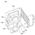
도 3은 본 발명의 제1실시예에 따른 내시경 시스템에 적용되는 광학 어셈블리(100) 및 제1광원 어셈블리(200)의 모습을 나타낸 도면이다.3 is a view showing an
도 3에 도시된 바와 같이, 본 실시예에서 상기 광학 어셈블리(100)는 상부 케이스(100b) 및 하부 케이스(100a)로 분할된 케이스(110)를 포함하며, 상기 광학 어셈블리(100)의 후방에는 제1광원 어셈블리(200)가 구비된다.3, in this embodiment, the
상기 광학 어셈블리(100)는 내부 광학계나 기구적인 조립성의 편의를 위해 상부 케이스 및 하부 케이스(100b, 100a)로 분할되어 구성됨이 바람직하지만, 광학계가 내부에 삽입될 수 있는 구조를 갖춘 하나의 단위 조립체로 형성될 수 있다.The
상기 제1광원 어셈블리(200)는 히트싱크 형태로 형성되는 냉각모듈(220)과, 상기 냉각모듈(220)에 의해 냉각되는 광학소자(212, 도 8 참조) 및 기판(214, 도 8 참조)를 포함하는 제1광원(210, 도 8 참조)과, 상기 제1광원(210) 및 상기 냉각모듈(220)을 지지하기 위한 고정프레임(240)을 포함한다.The first
그리고 상기 광학 어셈블리(100)의 측부에는 제2광원 어셈블리(300, 도 2 참조)로부터 빛을 전달하는 광 전달부(310)가 연결될 수 있다.A
이하에서는 먼저 상기 광학 어셈블리(100)에 대해 자세히 설명한 후, 상기 제1광원 어셈블리(200)의 구조에 대해 설명하도록 한다.Hereinafter, the
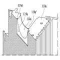
도 4는 본 발명의 제1실시예에 따른 내시경 시스템에 적용되는 광원장치에 있어서, 광학 어셈블리(100)의 구조를 나타낸 도면이다. 그리고 도 5는 본 발명의 제1실시예에 따른 내시경 시스템에 적용되는 광원장치에 있어서, 광학 어셈블리(100)의 하부 케이스(110a)를 나타낸 도면이며, 도 6은 본 발명의 제1실시예에 따른 내시경 시스템에 적용되는 광원장치에 있어서, 광학 어셈블리(100)의 상부 케이스(110b)를 나타낸 도면이다.FIG. 4 is a view showing a structure of an
도 4 내지 도 6에 도시된 바와 같이, 상기 광학 어셈블리(100)는, 케이스(110)와, 상기 케이스(110)의 내측에 결합되는 빔 스플릿터(150)와, 제1렌즈(120) 및 제2렌즈(125)와, 제1차폐블록(130) 및 제2차폐블록(140)을 포함한다.4 to 6, the
상기 케이스(110)는 내측에 제1광원으로부터 조사되는 빛을 통과시키는 제1광로(114a, 114b)와, 상기 제1광로(114a, 114b)의 측부에 연통되어 상기 제1광원과 다른 방향에서 제2광원으로부터 조사되는 빛을 상기 제1광로(114b) 내로 유입시키는 제2광로(112a, 112b)가 형성된다.The
그리고 전술한 바와 같이 본 실시예에서 상기 케이스(110)눈 상부 케이스(110b) 및 하부 케이스(110a)를 포함하며, 이들은 상기 케이스(110)의 내측에 형성된 제1광로(114a, 114b) 및 제2광로(112a, 112b)를 양분하도록 형성된다.As described above, in the present embodiment, the
상기 제1광로(114a, 114b)는 상기 광학 어셈블리(100)의 후방에 구비된 제1광원 어셈블리(200, 도 3 참조)의 제1광원으로부터 조사되는 빛을 통과시키는 경로를 형성하며, 본 실시예의 경우 상기 제1광로(114a, 114b)는 상기 케이스(110)의 후방으로부터 전방에 걸쳐 직선 형태로 관통하도록 형성된다.The first
그리고 상기 제2광로(112a, 112b)는 상기 제1광로(114a, 114b)의 중간 지점에서부터 수직한 측 방향으로 연장되며, 상기 광학 어셈블리(100)의 일측에 구비된 제2광원 어셈블리(300, 도 2 참조)의 제2광원으로부터 조사되는 빛을 통과시키는 경로를 형성한다. 즉 상기 제2광로(112a, 112b)를 통해 조사된 빛은 상기 제1광로(114a, 114b)와 상기 제2광로(112a, 112b)의 합류 지점에 도달하게 된다.The second
이때 상기 빔 스플릿터(150)는 상기 제1광로(114a, 114b) 상, 구체적으로는 상기 제1광로(114a, 114b)와 상기 제2광로(112a, 112b)의 합류 지점에 인접하게 구비된다.At this time, the
그리고 상기 빔 스플릿터(150)는 상기 제1광원으로부터 조사된 빛에 대해서는 진행 방향을 유지시키며, 상기 제2광원으로부터 조사된 빛에 대해서는 상기 제1광원으로부터 조사된 빛과 동일한 방향으로 진행되도록 빛의 방향을 전환시킨다. 즉 상기 제1광원으로부터 조사된 빛과 상기 제2광원으로부터 조사된 빛은 서로 다른 방향으로부터 조사되었으나, 상기 빔 스플릿터(150)에 의해 동일 방향으로 변환되어 내시경 측으로 전달될 수 있다.The
상기 빔 스플릿터(150)로는 다이크로닉 미러(Dichronic Mirror) 등이 적용될 수 있으며, 이외에도 다양한 광학적 미러가 적용될 수 있음은 물론이다.As the
특히 본 실시예에서 상기 제1광로(114a, 114b)의 내주면에는, 상기 빔 스플릿터(150)의 단면 형상에 대응되도록 형성되어 상기 빔 스플릿터(150)가 삽입 고정되는 삽입홈(119a, 119b)이 형성된다.Particularly, in this embodiment, the inner circumferential surfaces of the first
상기 삽입홈(119a, 119b)은 상기 제1광로(114a, 114b)와 상기 제2광로(112a, 112b)의 합류 지점에 인접하여 형성되며, 상기 제1광로(114a, 114b)와 상기 제2광로(112a, 112b) 각각에 대해 사선 방향으로 형성되어 상기 빔 스플릿터(150)를 고정시킨다.The
그리고 본 실시예에서 상기 케이스(110)는 상기 제1광로(114a, 114b)의 전단부에 형성된 제1렌즈결합부(115a, 115b)와, 상기 제1광로(114a, 114b)의 후단부에 형성된 제2렌즈결합부(116a, 116b)를 포함하며, 이에 따라 상기 제1렌즈결합부(115a, 115b)에는 제1렌즈(120)가, 상기 제2렌즈결합부(116a, 116b)에는 제2렌즈(125)가 결합될 수 있다.In this embodiment, the
상기 제1렌즈(120) 및 상기 제2렌즈(125)는 광학적 특성에 따라 빛의 투과도 등을 결정할 수 있으며, 본 실시예의 경우 상기 제1렌즈(120) 및 상기 제2렌즈(125)는 일면이 편평하게, 타면이 돌출된 형태로 가공되어, 타면 부분이 상기 빔 스플릿터(150) 측을 향하도록 구비된다. 이때 제1렌즈결합부(115a, 115b) 및 제2렌즈결합부(116a, 116b)는 상기 제1렌즈(120) 및 상기 제2렌즈(125)가 안정적으로 안착될 수 있도록 상기 제1렌즈(120) 및 상기 제2렌즈(125)의 둘레면 형상에 대응되는 단차를 가질 수 있다.The
또한 본 실시예에서 상기 광학 어셈블리(100)는, 상기 제1렌즈결합부(115a, 115b)의 전방을 차폐하도록 상기 케이스(110)에 결합되는 제1차폐블록(130)과, 상기 제2렌즈결합부(116a, 116b)의 후방을 차폐하도록 상기 케이스(110)에 결합되는 제2차폐블록(140)을 더 포함할 수 있다.The
상기 제1차폐블록(130) 및 상기 제2차폐블록(140)은 상기 제1렌즈(120) 및 상기 제2렌즈(125)가 상기 케이스(110)의 외부로 이탈되는 것을 방지할 수 있도록 하며, 구체적으로 상기 케이스(110)의 전단에 형성된 제1블록결합부(117a, 117b)에는 제1차폐블록(130)이 체결되고, 상기 케이스(110)의 후단에 형성된 제2블록결합부(118a, 118b)에는 제2차폐블록(140)이 체결된다.The
상기 제1차폐블록(130) 및 상기 제2차폐블록(140)에는 각각 빛이 통과할 수 있는 통과홀(131, 141)이 형성되며, 상기 통과홀(131, 141)의 직경은 상기 제1렌즈(120) 및 상기 제2렌즈(125)보다 작게 형성될 수 있다. 이는 상기 제1렌즈(120) 및 상기 제2렌즈(125)가 상기 통과홀(131, 141)을 통해 이탈되지 않도록 하기 위해서이다.The
한편, 제2차폐블록(140)의 경우엔, 광원에서 발생되는 열을 효과적으로 방열하기 위하여 도시된 바와 같이 테두리면이 요철형상을 갖을수 있다.Meanwhile, in the case of the
도 7은 본 발명의 제1실시예에 따른 내시경 시스템에 적용되는 광원장치에 있어서, 삽입홈(119a, 119b)의 구조를 나타낸 도면이다.7 is a view showing the structure of the
도 7에 도시된 바와 같이, 상기 삽입홈(119a, 119b)은 상기 제1광로(114a) 상에 비스듬한 형태로 가공되며, 상기 빔 스플릿터(150)의 형태에 대응되는 단면을 가진다.As shown in FIG. 7, the
본 실시예의 경우, 상기 빔 스플릿터(150)는 사각형 형태로 형성되므로, 상기 삽입홈(119a, 119b) 역시 상부 케이스(110b)와 하부 케이스(110a)를 결합시킨 상태에서 상기 빔 스플릿터(150)에 대응되는 크기의 사각형으로 형성된다. 빔 스플릿터(150)의 형상 및 상부 케이스(110b)와 하부 케이스(110a)을 결합한 상태로 만들어진 삽입홈(119a, 119b)의 형상은 특정 형상에 한정되지 않고, 조립성의 편의나 기능을 추가하기 위해선 어느 형태로 가능하다.The
이에 따라 상기 상부 케이스(110b)와 상기 하부 케이스(110a)를 서로 분리시킨 상태에서 상기 빔 스플릿터(150)의 하부를 상기 하부 케이스(110a)의 삽입홈(119a)에 삽입한 뒤, 상기 상부 케이스(110b)의 삽입홈(119b)을 상기 빔 스플릿터(150)의 상부에 끼워 넣으며 상기 상부 케이스(110b)와 상기 하부 케이스(110a)를 서로 결합시킬 수 있다.The lower portion of the
이와 같이 본 발명은 상기 케이스(110)가 상기 상부 케이스(110b)와 상기 하부 케이스(110a)로 분할됨에 따라 상기 빔 스플릿터(150)의 결합 및 분리를 용이하게 수행할 수 있어 유지보수, 교체 등에 유리하다.As described above, according to the present invention, when the
한편 본 실시예의 경우 상기 삽입홈(119a, 119b)의 양단에는 상기 삽입홈(119a, 119b)의 두께 방향으로 돌출된 보조홈(119a')이 형성되며, 이는 상기 빔 스플릿터(150)를 용이하게 삽입할 수 있도록 할 수 있다.In the present embodiment,
또한 상기 빔 스플릿터(150)의 양단에 상기 보조홈(119a')에 삽입될 수 있도록 대응되는 형태의 보조가이드(미도시)를 형성할 경우에는 상기 빔 스플릿터(150)가 상기 삽입홈(119a, 119b)에 보다 안정적으로 흔들림 없이 고정될 수 있다.When auxiliary guides (not shown) are formed at both ends of the
다음으로 상기 제1광원 어셈블리(200)의 구조에 대해 설명하도록 한다.Next, the structure of the first
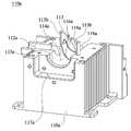
도 8은 본 발명의 제1실시예에 따른 내시경 시스템에 적용되는 광원장치에 있어서, 제1광원 어셈블리(200)의 구조를 나타낸 도면이며, 도 9는 본 발명의 제1실시예에 따른 내시경 시스템에 적용되는 광원장치에 있어서, 냉각모듈의(220) 분리 구조를 나타낸 도면이다.FIG. 8 is a diagram illustrating the structure of a first
도 8 및 도 9에 도시된 바와 같이, 제1광원 어셈블리(200)는 광학소자(212) 및 기판(214)을 포함하는 제1광원(210)과, 냉각모듈(220)과, 고정프레임(240)을 포함한다.8 and 9, the first
상기 광학소자(212)는 전술한 광학 어셈블리(100)의 후방에 구비되어 제1광로(114a, 114b)에 제1광을 조사하고, 커넥터(215)와 착탈 가능하도록 형성된 기판(214)에 실장되며, 케이블(216)를 통하여 내부에 설치된 구동 전원과 전기적으로 연결된다..The
또한 상기 기판(214)에는 발열이 심하게 발생할 수 있어, 상기 기판(214)의 후방에는 상기 냉각모듈(220)이 접촉된 상태로 구비된다. 상기 냉각모듈(220)은 내부에 복수의 중공이 형성된 냉각핀 형태로 형성되며, 특히 상기 냉각모듈(220)과 상기 기판(214) 사이에는 상기 기판(214)이 직접적으로 접촉되는 연결부재(230)가 구비된다.In addition, the
상기 연결부재(230)는 상기 냉각모듈(220)과 결합되고, 상기 기판(214)에서 발생하는 열을 상기 냉각모듈(220)에 빠르게 전달할 수 있도록 열 전도성이 우수한 소재로 형성될 수 있다.The
그리고 상기 제1광원(210)은 상기 연결부재(230)와 일체형 혹은 볼트와 같은 결합구를 이용하여 상기 연결부재(230)에 결합될 수 있다.The first
상기 고정프레임(240)은 상기 기판(214)을 포함하는 제1광원(210) 및 상기 냉각모듈(220)을 전체를 지지하는 구성요소로서, 본 실시예에서 상기 고정프레임(240)은 상기 냉각모듈(220)의 후방을 차폐하는 후방차폐부(240b) 및 일측을 차폐하는 측방차폐부(240a)를 포함한다. 여기서 설명의 편의 상 상기 일측이라 함은, 상기 냉각모듈(220)의 후방에서 바라볼 때 우측인 것으로 하며, 타측은 상기 냉각모듈(220)의 후방에서 바라볼 때 좌측인 것으로 한다.The fixing
즉 상기 고정프레임(240)은 상기 냉각모듈(220)과 볼트 등에 의해 결합되어 상기 냉각모듈(220)을 고정시킬 수 있으며, 상기 제1광원(210)으로부터 열이 전달되어 온도가 상승하는 것을 방지하도록 표면에는 복수의 타공이 형성될 수 있다.That is, the fixing
그리고 본 실시예에서 상기 냉각모듈(220), 상기 연결부재(230) 및 제1광원(210)은 상기 고정프레임(240)으로부터 타측 방향으로 슬라이딩시켜 분리 가능하게 하나의 단위 구성체를 형성한다. 이와 같이 하는 이유는 상기 제1광원(210) 또는 상기 냉각모듈(220)의 분리를 용이하게 하여 유지보수 및 교체 작업을 원활히 할 수 있도록 하기 위해서이다. 이를 위해 상기 냉각모듈(220)의 타측에는 사용자가 그립하여 상기 냉각모듈(220)을 인출할 수 있도록 손잡이부(222)가 형성될 수 있다.In this embodiment, the
즉 상기 제1광원(210) 또는 상기 냉각모듈(220)의 교체 또는 보수 등이 필요한 경우, 사용자는 상상기 커넥터(215)로부터 제1광원(210)을 분리시킴과 동시에 냉각모듈(220)의 체결 상태를 해제하고 상기 손잡이부(222)를 이용하여 타측 방향으로 인출할 수 있다.That is, when it is necessary to replace or repair the first
한편 상기 고정프레임(240)의 상기 측방차폐부(240a)에는, 상기 기판(214)을 일측으로 인출 가능하도록 하는 인출홀(241)이 형성될 수 있다. 이는 상기 냉각모듈(220)을 타측 방향으로 분리하는 것과 마찬가지로, 상기 제1광원(210)과 연결되는 커넥터(215)의 유지보수 및 교체 등이 필요할 경우, 상기 커넥터(215)를 상기 냉각모듈(220)과 반대 방향으로 분리할 수 있도록 하기 위한 것이다.On the other hand, the
이상으로 본 발명의 제1실시예에 대해 설명하였으며, 이하에서는 본 발명의 다른 실시예들에 대해 설명하도록 한다.The first embodiment of the present invention has been described above, and other embodiments of the present invention will be described below.
도 10은 본 발명의 제2실시예에 따른 내시경 시스템에 적용되는 광원장치에 있어서, 광학 어셈블리의 하부 케이스(110a)를 나타낸 도면이며, 도 11은 본 발명의 제2실시예에 따른 내시경 시스템에 적용되는 광원장치에 있어서, 광학 어셈블리의 상부 케이스(110b)를 나타낸 도면이다.FIG. 10 is a view showing a
도 10 및 도 11에 도시된 본 발명의 제2실시예에 따른 광학 어셈블리의 경우, 전술한 제1실시예와 모든 구성요소가 동일하게 형성된다. 다만, 상기 빔 스플릿터(150)를 고정시키기 위한 구성요소가 다소 다르게 형성된다.In the case of the optical assembly according to the second embodiment of the present invention shown in Figs. 10 and 11, all the components are the same as those of the first embodiment described above. However, the components for fixing the
구체적으로 본 실시예에서 상기 하부 케이스(110a)는, 상기 하부 케이스(110a)의 상부로 돌출되어 상기 상부 케이스(110b)에 삽입 가능하게 형성되고, 내측에 상기 하부 케이스(110a)의 삽입홈(119a)과 연통되는 연통홈(113a)이 형성된 가이드부(113)를 더 포함한다.Specifically, in the present embodiment, the
상기 가이드부(113)는 상기 빔 스플릿터(150)를 상기 하부 케이스(110a)의 삽입홈(119a)에 보다 용이하게 삽입할 수 있도록 하는 동시에, 상기 빔 스플릿터(150)가 상기 삽입홈(119a, 119b)에 삽입된 상태에서 외부의 충격 등에 의해 흔들리거나 파손되는 것을 방지하는 역할을 수행한다.The
이때 상기 상부 케이스(110b)의 가이드홈(119b')은, 상기 가이드부(113)가 삽입될 수 있도록 상기 가이드부(113)에 대응되는 두께를 가지도록 형성될 수 있다.At this time, the
도 12는 본 발명의 제3실시예에 따른 내시경 시스템에 적용되는 광원장치에 있어서, 광학 어셈블리의 하부 케이스(110a)를 나타낸 도면이다.12 is a view showing a
도 12에 도시된 본 발명의 제3실시예 역시 전술한 제2실시예와 마찬가지로, 상기 하부 케이스(110a)는 상부로 돌출된 가이드부(113)를 더 포함한다.12, the
다만, 본 실시예의 가이드부(113)의 경우 내측에 연통홈이 형성된 형태가 아니라 양단에 가이드단차부(113b)가 형성되며, 이에 따라 상기 빔 스플릿터(150)는 상기 가이드부(113)의 전방에 안착된 상태로 상기 하부 케이스(110a)의 삽입홈(119a)에 삽입될 수 있다.In the
또한 본 실시예 역시 마찬가지로 상기 상부 케이스(110b)의 삽입홈(119b)은 상기 가이드부(113)가 삽입될 수 있도록 상기 가이드부(113)에 대응되는 두께를 가지도록 형성될 수 있다.Also in this embodiment, the
도 13은 본 발명의 제4실시예에 따른 내시경 시스템에 적용되는 광원장치에 있어서, 광학 어셈블리의 하부 케이스(110a)를 나타낸 도면이다.13 is a view showing a
도 13에 도시된 본 발명의 제4실시예 역시 전술한 제2실시예 및 제3실시예와 마찬가지로, 상기 하부 케이스(110a)는 상부로 돌출된 가이드부(113)를 더 포함한다.13, the
다만, 본 실시예의 가이드부(113)는 한 쌍이 형성되어, 각각 상기 하부 케이스(110a)의 삽입홈(119a) 양단으로부터 기립된 상태를 가진다. 또한 상기 한 쌍의 가이드부(113) 내측에는 상기 하부 케이스(110a)의 삽입홈(119a)과 연통된 연통홈(113a)이 형성된다.However, the
이에 따라 상기 빔 스플릿터(150)는 상기 한 쌍의 가이드부(113) 사이에 안정적으로 삽입될 수 있다.Accordingly, the
또한 본 실시예 역시 마찬가지로 상기 상부 케이스(110b)의 삽입홈(119b)은 상기 한 쌍의 가이드부(113)가 삽입될 수 있도록 양단이 상기 가이드부(113)에 대응되는 두께를 가지도록 형성될 수 있다.The
이상과 같이 본 발명에 따른 바람직한 실시예를 살펴보았으며, 앞서 설명된 실시예 이외에도 본 발명이 그 취지나 범주에서 벗어남이 없이 다른 특정 형태로 구체화될 수 있다는 사실은 해당 기술에 통상의 지식을 가진 이들에게는 자명한 것이다. 그러므로, 상술된 실시예는 제한적인 것이 아니라 예시적인 것으로 여겨져야 하고, 이에 따라 본 발명은 상술한 설명에 한정되지 않고 첨부된 청구항의 범주 및 그 동등 범위 내에서 변경될 수도 있다.It will be apparent to those skilled in the art that the present invention can be embodied in other specific forms without departing from the spirit or scope of the invention as defined in the appended claims. It is obvious to them. Therefore, the above-described embodiments are to be considered as illustrative rather than restrictive, and the present invention is not limited to the above description, but may be modified within the scope of the appended claims and equivalents thereof.
100: 광학 어셈블리
110: 케이스
110a: 하부 케이스
110b: 상부 케이스
112a, 112b: 제2광로
114a, 114b: 제1광로
115a, 115b: 제1렌즈결합부
116a, 116b: 제2렌즈결합부
117a, 117b: 제1블록결합부
118a, 118b: 제2블록결합부
119a: 삽입홈
119a': 보조홈
119b': 가이드홈
120: 제1렌즈
125: 제2렌즈
130: 제1차폐블록
140: 제2차폐블록
150: 빔 스플릿터
200: 제1광원 어셈블리
210: 제1광원
212: 광학소자
214: 기판
215: 커넥터
216: 케이블
220: 냉각모듈
222: 손잡이부
230: 연결부재
240: 고정프레임
240a: 측방차폐부
240b: 후방차폐부
300: 제2광원 어셈블리100: Optical assembly
110: Case
110a: Lower case
110b: upper case
112a and 112b:
114a and 114b:
115a and 115b: a first lens-
116a, 116b: a second lens-
117a and 117b:
118a, 118b:
119a: insertion groove
119a ': auxiliary groove
119b ': Guide groove
120: first lens
125: Second lens
130: first shielding block
140: Second shielding block
150: beam splitter
200: First light source assembly
210: a first light source
212: optical element
214: substrate
215: Connector
216: Cable
220: Cooling module
222: handle portion
230: connection member
240: Fixed frame
240a: Side shield
240b: rear shield
300: second light source assembly
Claims (11)
Translated fromKorean상기 상부 케이스와 대응되게 형성되어 상기 상부 케이스와 결합되는 하부 케이스; 및
상기 제1광로에 구비되어, 상기 제1광원으로부터 조사된 빛에 대해서는 진행 방향을 유지시키며, 상기 제2광원으로부터 조사된 빛에 대해서는 상기 제1광원으로부터 조사된 빛과 수평하도록 진행 방향으로 변경시키는 빔 스플릿터;
를 포함하는 광학 어셈블리.A first optical path through which light irradiated from the first light source passes and a second optical path through which light irradiated from the second light source in a direction different from the first light source is communicated with the side of the first light path, An upper case formed on the inner side;
A lower case formed to correspond to the upper case and coupled with the upper case; And
Wherein the first light source maintains the traveling direction of the light emitted from the first light source and changes the light emitted from the second light source to the traveling direction so as to be horizontal with the light emitted from the first light source Beam splitter;
≪ / RTI >
상기 상부 케이스 및 상부 하부 케이스 각각은,
상기 제1광로의 전단부에 형성된 제1렌즈결합부 및 상기 제1광로의 후단부에 형성된 제2렌즈결합부를 포함하며,
상기 광학 어셈블리는,
상기 제1렌즈결합부에 결합되는 제1렌즈 및 상기 제2렌즈결합부에 결합되는 제2렌즈를 더 포함하는 광학 어셈블리.The method according to claim 1,
Each of the upper case and the upper lower case includes:
A first lens coupling portion formed at a front end portion of the first optical path and a second lens coupling portion formed at a rear end portion of the first optical path,
The optical assembly includes:
Further comprising a first lens coupled to the first lens coupling portion and a second lens coupled to the second lens coupling portion.
상기 광학 어셈블리는,
상기 제1렌즈결합부의 전방을 차폐하도록 상기 상부 케이스 및 상기 하부 케이스에 결합되는 제1차폐블록 및 상기 제2렌즈결합부의 후방을 차폐하도록 상기 상부 케이스 및 상기 하부 케이스에 결합되는 제2차폐블록을 더 포함하는 광학 어셈블리.3. The method of claim 2,
The optical assembly includes:
A first shielding block coupled to the upper case and the lower case to shield the front of the first lens coupling portion and a second shielding block coupled to the upper case and the lower case to shield the rear of the second lens coupling portion, Further comprising an optical assembly.
상기 상부 케이스 및 상기 하부 케이스에 형성된 상기 제1광로의 내주면에는 상기 빔 스플릿터의 단면 형상에 대응되는 삽입홈이 형성되어,
상기 빔 스플릿터가 상기 삽입홈에 삽입 고정되는 광학 어셈블리.The method according to claim 1,
An insertion groove corresponding to a sectional shape of the beam splitter is formed on an inner circumferential surface of the first optical path formed in the upper case and the lower case,
And the beam splitter is inserted and fixed in the insertion groove.
상기 하부 케이스는,
제1광로의 내주면에 상기 빔 스플릿터의 단면 형상에 대응되도록 삽입홈이 형성되고, 상기 하부 케이스의 상부로 돌출되어 상기 빔 스플릿터가 상기 삽입홈에 삽입 가능하게 형성된 가이드부를 포함하고,
상기 상부 케이스는,
상기 하부 케이스의 가이드부가 상기 상부 케이스에 삽입 가능하게 형성된 가이드홈을 포함하는 광학 어셈블리.The method according to claim 1,
The lower case includes:
And a guide portion formed on an inner circumferential surface of the first optical path so as to correspond to a sectional shape of the beam splitter and protruding from an upper portion of the lower case so that the beam splitter can be inserted into the insertion groove,
The upper case includes:
And a guide portion of the lower case includes a guide groove formed to be insertable into the upper case.
상기 가이드부는,
상기 하부 케이스의 삽입홈과 연통되는 연통홈이 형성되고, 상기 빔스플릿터는 상기 가이드부의 연통홈을 따라 슬라이딩되어 상기 하부 케이스의 삽입홈에 삽입되는 광학 어셈블리.6. The method of claim 5,
The guide portion
Wherein a communication groove communicating with the insertion groove of the lower case is formed and the beam splitter is slid along the communication groove of the guide portion and inserted into the insertion groove of the lower case.
상기 광학 어셈블리의 후방에 구비되어 상기 제1광로에 제1광원을 조사하는 광학소자를 포함하는 제1광원 어셈블리를 포함하는 내시경용 광원장치.A first optical path through which light irradiated from the first light source passes and a second optical path through which light irradiated from the second light source in a direction different from the first light source is communicated with the side of the first light path, An upper case formed on the inner side; A lower case formed to correspond to the upper case and coupled with the upper case; Wherein the first light source maintains the traveling direction of the light emitted from the first light source and changes the light emitted from the second light source to the traveling direction so as to be horizontal with the light emitted from the first light source Beam splitter; An optical assembly comprising: And
And a first light source assembly disposed at the rear of the optical assembly and including an optical element for irradiating the first light source to the first optical path.
상기 제1광원 어셈블리는,
상기 광학소자가 구비된 기판;
상기 기판의 후방에 접촉되어 냉각을 수행하는 냉각모듈; 및
상기 기판 및 상기 냉각모듈을 고정시키는 고정프레임;
을 포함하는 내시경용 광원장치.8. The method of claim 7,
The first light source assembly includes:
A substrate provided with the optical element;
A cooling module for contacting the rear of the substrate to perform cooling; And
A fixing frame for fixing the substrate and the cooling module;
And a light source for illuminating the endoscope.
상기 고정프레임은 상기 냉각모듈의 후방을 차폐하는 후방차폐부 및 일측을 차폐하는 측방차폐부를 포함하는 내시경용 광원장치.9. The method of claim 8,
Wherein the fixing frame includes a rear shielding part for shielding the rear of the cooling module and a side shielding part for shielding the one side.
상기 기판 및 냉각모듈은 상기 고정프레임으로부터 타측 방향으로 분리 가능하게 형성된 내시경용 광원장치.9. The method of claim 8,
Wherein the substrate and the cooling module are detachable from the fixed frame in the other direction.
상기 측방차폐부에는 상기 기판에 연결되는 커넥터를 일측으로 인출 가능하도록 하는 인출홀이 형성된 내시경용 광원장치.
10. The method of claim 9,
Wherein the lateral shielding portion is provided with a lead-out hole for allowing a connector connected to the substrate to be drawn out to one side.
Priority Applications (4)
| Application Number | Priority Date | Filing Date | Title |
|---|---|---|---|
| KR1020170053980AKR101877921B1 (en) | 2017-04-26 | 2017-04-26 | Optic assembly and light source device for endoscope including the same |
| US15/648,420US10394013B2 (en) | 2017-04-26 | 2017-07-12 | Optic assembly and light source device for endoscope including the same |
| CN201710565475.9ACN108803000B (en) | 2017-04-26 | 2017-07-12 | Optical module and endoscope light source device including the same |
| CN201720841424.XUCN207396854U (en) | 2017-04-26 | 2017-07-12 | Optical module and the light source device for endoscope for including it |
Applications Claiming Priority (1)
| Application Number | Priority Date | Filing Date | Title |
|---|---|---|---|
| KR1020170053980AKR101877921B1 (en) | 2017-04-26 | 2017-04-26 | Optic assembly and light source device for endoscope including the same |
Publications (1)
| Publication Number | Publication Date |
|---|---|
| KR101877921B1true KR101877921B1 (en) | 2018-07-12 |
Family
ID=62417665
Family Applications (1)
| Application Number | Title | Priority Date | Filing Date |
|---|---|---|---|
| KR1020170053980AExpired - Fee RelatedKR101877921B1 (en) | 2017-04-26 | 2017-04-26 | Optic assembly and light source device for endoscope including the same |
Country Status (3)
| Country | Link |
|---|---|
| US (1) | US10394013B2 (en) |
| KR (1) | KR101877921B1 (en) |
| CN (2) | CN108803000B (en) |
Cited By (1)
| Publication number | Priority date | Publication date | Assignee | Title |
|---|---|---|---|---|
| KR20180123812A (en)* | 2017-05-10 | 2018-11-20 | 인더스마트 주식회사 | Optic assembly and light source device for endoscope including the same |
Families Citing this family (3)
| Publication number | Priority date | Publication date | Assignee | Title |
|---|---|---|---|---|
| KR101877921B1 (en)* | 2017-04-26 | 2018-07-12 | 인더스마트 주식회사 | Optic assembly and light source device for endoscope including the same |
| CN110786817B (en)* | 2019-11-13 | 2021-11-23 | 山西医科大学 | Two-waveband optical molecular image light source device based on LED efficient refrigeration |
| CN114869200A (en)* | 2022-05-13 | 2022-08-09 | 深圳英术生命科技有限公司 | Portable electronic endoscope |
Citations (6)
| Publication number | Priority date | Publication date | Assignee | Title |
|---|---|---|---|---|
| JP2005342350A (en)* | 2004-06-04 | 2005-12-15 | Pentax Corp | Endoscope illumination optics |
| JP2005348794A (en)* | 2004-06-08 | 2005-12-22 | Pentax Corp | Endoscope light source device |
| KR20100032742A (en)* | 2008-09-18 | 2010-03-26 | 고려대학교 산학협력단 | Living body surface morphological measuring system |
| KR20120096725A (en)* | 2011-02-23 | 2012-08-31 | (주)용아산업 | Deformation measurement apparatus using stimulus |
| JP2013123477A (en)* | 2011-12-13 | 2013-06-24 | Olympus Corp | Radiation module having plurality of light guide members |
| WO2014109333A1 (en)* | 2013-01-10 | 2014-07-17 | ゼロラボ株式会社 | Wavelength conversion device, lighting optical system, and electronic device using same |
Family Cites Families (12)
| Publication number | Priority date | Publication date | Assignee | Title |
|---|---|---|---|---|
| US4273431A (en)* | 1979-08-02 | 1981-06-16 | Polaroid Corporation | Adapter for coupling a photographic camera with a viewing device |
| US6369893B1 (en)* | 1998-05-19 | 2002-04-09 | Cepheid | Multi-channel optical detection system |
| EP1158325A3 (en)* | 2000-05-22 | 2004-03-31 | Alps Electric Co., Ltd. | Beam-splitting/coupling apparatus having frame holding optical filter |
| CN201189159Y (en)* | 2008-04-29 | 2009-02-04 | 宁波明视数字技术有限公司 | Endoscope lens |
| CN201293875Y (en)* | 2008-11-12 | 2009-08-19 | 无锡市星迪仪器有限公司 | Light beam splitter |
| US8278841B2 (en)* | 2009-07-02 | 2012-10-02 | Innovations In Optics, Inc. | Light emitting diode light engine |
| JP5174290B2 (en)* | 2011-01-28 | 2013-04-03 | オリンパスメディカルシステムズ株式会社 | Illumination device and observation system |
| US9217561B2 (en)* | 2012-06-15 | 2015-12-22 | Lumencor, Inc. | Solid state light source for photocuring |
| CN203825196U (en)* | 2014-02-25 | 2014-09-10 | 江苏徕兹光电科技有限公司 | Internal and external optical-path switching device of laser range finder |
| DE112015002789T5 (en)* | 2014-07-09 | 2017-03-02 | Olympus Corporation | Endoscope system and endoscope light source device |
| CN106526874B (en)* | 2016-12-09 | 2023-07-07 | 深圳开立生物医疗科技股份有限公司 | Optical coupling device, light source system and endoscope system |
| KR101877921B1 (en)* | 2017-04-26 | 2018-07-12 | 인더스마트 주식회사 | Optic assembly and light source device for endoscope including the same |
- 2017
- 2017-04-26KRKR1020170053980Apatent/KR101877921B1/ennot_activeExpired - Fee Related
- 2017-07-12CNCN201710565475.9Apatent/CN108803000B/ennot_activeExpired - Fee Related
- 2017-07-12CNCN201720841424.XUpatent/CN207396854U/ennot_activeWithdrawn - After Issue
- 2017-07-12USUS15/648,420patent/US10394013B2/enactiveActive
Patent Citations (6)
| Publication number | Priority date | Publication date | Assignee | Title |
|---|---|---|---|---|
| JP2005342350A (en)* | 2004-06-04 | 2005-12-15 | Pentax Corp | Endoscope illumination optics |
| JP2005348794A (en)* | 2004-06-08 | 2005-12-22 | Pentax Corp | Endoscope light source device |
| KR20100032742A (en)* | 2008-09-18 | 2010-03-26 | 고려대학교 산학협력단 | Living body surface morphological measuring system |
| KR20120096725A (en)* | 2011-02-23 | 2012-08-31 | (주)용아산업 | Deformation measurement apparatus using stimulus |
| JP2013123477A (en)* | 2011-12-13 | 2013-06-24 | Olympus Corp | Radiation module having plurality of light guide members |
| WO2014109333A1 (en)* | 2013-01-10 | 2014-07-17 | ゼロラボ株式会社 | Wavelength conversion device, lighting optical system, and electronic device using same |
Cited By (2)
| Publication number | Priority date | Publication date | Assignee | Title |
|---|---|---|---|---|
| KR20180123812A (en)* | 2017-05-10 | 2018-11-20 | 인더스마트 주식회사 | Optic assembly and light source device for endoscope including the same |
| KR101975908B1 (en) | 2017-05-10 | 2019-05-07 | 인더스마트 주식회사 | Optic assembly and light source device for endoscope including the same |
Also Published As
| Publication number | Publication date |
|---|---|
| CN108803000B (en) | 2021-06-01 |
| US20180314055A1 (en) | 2018-11-01 |
| CN207396854U (en) | 2018-05-22 |
| CN108803000A (en) | 2018-11-13 |
| US10394013B2 (en) | 2019-08-27 |
Similar Documents
| Publication | Publication Date | Title |
|---|---|---|
| KR101877921B1 (en) | Optic assembly and light source device for endoscope including the same | |
| JP6717752B2 (en) | Medical devices for diagnosis and treatment | |
| JP7151109B2 (en) | Medical imaging device and medical observation system | |
| JP6197232B2 (en) | Endoscope with removable tip | |
| US9125553B2 (en) | Endoscope with electrical conductive portion | |
| US20080039693A1 (en) | Endoscope tip unit and endoscope with scanning optical fiber | |
| US20140221740A1 (en) | Wireless endoscopic surgical device | |
| JP7328432B2 (en) | medical control device, medical observation system, control device and observation system | |
| JP2008173397A (en) | Endoscope system | |
| JP6529703B2 (en) | Imaging unit and endoscope | |
| JP5184964B2 (en) | Endoscope system and connector cover | |
| JP5085142B2 (en) | Endoscope system and method for operating apparatus for detecting shape of endoscope insertion portion used therefor | |
| KR101975908B1 (en) | Optic assembly and light source device for endoscope including the same | |
| JP6302863B2 (en) | Endoscope device | |
| US20180329198A1 (en) | Electrostatic touch assembly of light source device for endoscope and endoscope system including the same | |
| JP6450873B2 (en) | Endoscope device | |
| RU2709825C1 (en) | Medical light source module and a medical lighting device with a light source, including such a module | |
| WO2015125344A1 (en) | Imaging unit | |
| WO2019193911A1 (en) | Imaging unit and endoscope | |
| JP6502785B2 (en) | MEDICAL OBSERVATION DEVICE, CONTROL DEVICE, CONTROL DEVICE OPERATION METHOD, AND CONTROL DEVICE OPERATION PROGRAM | |
| JP2008173396A (en) | Endoscope system | |
| KR20200070912A (en) | Image picup module for endoscope and medical endoscope synchronized multiplex medical image based on separate imaging | |
| JP2019165855A (en) | Endoscope device and medical imaging device | |
| US20250082187A1 (en) | Medical Imaging Device with Heat Dissipation and Method for Regulating Heat Generated within a Medical Imaging Device | |
| JP5288909B2 (en) | Endoscope system and switch |
Legal Events
| Date | Code | Title | Description |
|---|---|---|---|
| PA0109 | Patent application | St.27 status event code:A-0-1-A10-A12-nap-PA0109 | |
| PA0201 | Request for examination | St.27 status event code:A-1-2-D10-D11-exm-PA0201 | |
| PA0302 | Request for accelerated examination | St.27 status event code:A-1-2-D10-D16-exm-PA0302 St.27 status event code:A-1-2-D10-D17-exm-PA0302 | |
| PE0902 | Notice of grounds for rejection | St.27 status event code:A-1-2-D10-D21-exm-PE0902 | |
| P11-X000 | Amendment of application requested | St.27 status event code:A-2-2-P10-P11-nap-X000 | |
| P13-X000 | Application amended | St.27 status event code:A-2-2-P10-P13-nap-X000 | |
| E701 | Decision to grant or registration of patent right | ||
| PE0701 | Decision of registration | St.27 status event code:A-1-2-D10-D22-exm-PE0701 | |
| GRNT | Written decision to grant | ||
| PR0701 | Registration of establishment | St.27 status event code:A-2-4-F10-F11-exm-PR0701 | |
| PR1002 | Payment of registration fee | Fee payment year number:1 St.27 status event code:A-2-2-U10-U11-oth-PR1002 | |
| PG1601 | Publication of registration | St.27 status event code:A-4-4-Q10-Q13-nap-PG1601 | |
| PR1001 | Payment of annual fee | Fee payment year number:4 St.27 status event code:A-4-4-U10-U11-oth-PR1001 | |
| PR1001 | Payment of annual fee | Fee payment year number:5 St.27 status event code:A-4-4-U10-U11-oth-PR1001 | |
| PC1903 | Unpaid annual fee | Not in force date:20230707 Payment event data comment text:Termination Category : DEFAULT_OF_REGISTRATION_FEE St.27 status event code:A-4-4-U10-U13-oth-PC1903 | |
| P22-X000 | Classification modified | St.27 status event code:A-4-4-P10-P22-nap-X000 | |
| PC1903 | Unpaid annual fee | Ip right cessation event data comment text:Termination Category : DEFAULT_OF_REGISTRATION_FEE Not in force date:20230707 St.27 status event code:N-4-6-H10-H13-oth-PC1903 | |
| R18-X000 | Changes to party contact information recorded | St.27 status event code:A-5-5-R10-R18-oth-X000 |