KR101873476B1 - Organic light emitting diode display and manufacturing method thereof - Google Patents
Organic light emitting diode display and manufacturing method thereofDownload PDFInfo
- Publication number
- KR101873476B1 KR101873476B1KR1020110033395AKR20110033395AKR101873476B1KR 101873476 B1KR101873476 B1KR 101873476B1KR 1020110033395 AKR1020110033395 AKR 1020110033395AKR 20110033395 AKR20110033395 AKR 20110033395AKR 101873476 B1KR101873476 B1KR 101873476B1
- Authority
- KR
- South Korea
- Prior art keywords
- organic
- light emitting
- film
- inorganic
- organic film
- Prior art date
- Legal status (The legal status is an assumption and is not a legal conclusion. Google has not performed a legal analysis and makes no representation as to the accuracy of the status listed.)
- Active
Links
Images


Classifications
- H—ELECTRICITY
- H10—SEMICONDUCTOR DEVICES; ELECTRIC SOLID-STATE DEVICES NOT OTHERWISE PROVIDED FOR
- H10K—ORGANIC ELECTRIC SOLID-STATE DEVICES
- H10K59/00—Integrated devices, or assemblies of multiple devices, comprising at least one organic light-emitting element covered by group H10K50/00
- H10K59/80—Constructional details
- H10K59/87—Passivation; Containers; Encapsulations
- H10K59/871—Self-supporting sealing arrangements
- H10K59/8722—Peripheral sealing arrangements, e.g. adhesives, sealants
- H—ELECTRICITY
- H10—SEMICONDUCTOR DEVICES; ELECTRIC SOLID-STATE DEVICES NOT OTHERWISE PROVIDED FOR
- H10K—ORGANIC ELECTRIC SOLID-STATE DEVICES
- H10K59/00—Integrated devices, or assemblies of multiple devices, comprising at least one organic light-emitting element covered by group H10K50/00
- H10K59/80—Constructional details
- H10K59/87—Passivation; Containers; Encapsulations
- H10K59/873—Encapsulations
- H10K59/8731—Encapsulations multilayered coatings having a repetitive structure, e.g. having multiple organic-inorganic bilayers
- H—ELECTRICITY
- H01—ELECTRIC ELEMENTS
- H01L—SEMICONDUCTOR DEVICES NOT COVERED BY CLASS H10
- H01L23/00—Details of semiconductor or other solid state devices
- H01L23/28—Encapsulations, e.g. encapsulating layers, coatings, e.g. for protection
- H01L23/31—Encapsulations, e.g. encapsulating layers, coatings, e.g. for protection characterised by the arrangement or shape
- H—ELECTRICITY
- H10—SEMICONDUCTOR DEVICES; ELECTRIC SOLID-STATE DEVICES NOT OTHERWISE PROVIDED FOR
- H10H—INORGANIC LIGHT-EMITTING SEMICONDUCTOR DEVICES HAVING POTENTIAL BARRIERS
- H10H20/00—Individual inorganic light-emitting semiconductor devices having potential barriers, e.g. light-emitting diodes [LED]
- H10H20/80—Constructional details
- H10H20/85—Packages
- H10H20/852—Encapsulations
- H10H20/853—Encapsulations characterised by their shape
- H—ELECTRICITY
- H10—SEMICONDUCTOR DEVICES; ELECTRIC SOLID-STATE DEVICES NOT OTHERWISE PROVIDED FOR
- H10K—ORGANIC ELECTRIC SOLID-STATE DEVICES
- H10K30/00—Organic devices sensitive to infrared radiation, light, electromagnetic radiation of shorter wavelength or corpuscular radiation
- H10K30/80—Constructional details
- H10K30/88—Passivation; Containers; Encapsulations
- H—ELECTRICITY
- H10—SEMICONDUCTOR DEVICES; ELECTRIC SOLID-STATE DEVICES NOT OTHERWISE PROVIDED FOR
- H10K—ORGANIC ELECTRIC SOLID-STATE DEVICES
- H10K50/00—Organic light-emitting devices
- H10K50/80—Constructional details
- H10K50/84—Passivation; Containers; Encapsulations
- H—ELECTRICITY
- H10—SEMICONDUCTOR DEVICES; ELECTRIC SOLID-STATE DEVICES NOT OTHERWISE PROVIDED FOR
- H10K—ORGANIC ELECTRIC SOLID-STATE DEVICES
- H10K50/00—Organic light-emitting devices
- H10K50/80—Constructional details
- H10K50/84—Passivation; Containers; Encapsulations
- H10K50/842—Containers
- H10K50/8426—Peripheral sealing arrangements, e.g. adhesives, sealants
- H—ELECTRICITY
- H10—SEMICONDUCTOR DEVICES; ELECTRIC SOLID-STATE DEVICES NOT OTHERWISE PROVIDED FOR
- H10K—ORGANIC ELECTRIC SOLID-STATE DEVICES
- H10K50/00—Organic light-emitting devices
- H10K50/80—Constructional details
- H10K50/84—Passivation; Containers; Encapsulations
- H10K50/844—Encapsulations
- H10K50/8445—Encapsulations multilayered coatings having a repetitive structure, e.g. having multiple organic-inorganic bilayers
- H—ELECTRICITY
- H10—SEMICONDUCTOR DEVICES; ELECTRIC SOLID-STATE DEVICES NOT OTHERWISE PROVIDED FOR
- H10K—ORGANIC ELECTRIC SOLID-STATE DEVICES
- H10K50/00—Organic light-emitting devices
- H10K50/80—Constructional details
- H10K50/85—Arrangements for extracting light from the devices
- H10K50/858—Arrangements for extracting light from the devices comprising refractive means, e.g. lenses
- H—ELECTRICITY
- H10—SEMICONDUCTOR DEVICES; ELECTRIC SOLID-STATE DEVICES NOT OTHERWISE PROVIDED FOR
- H10K—ORGANIC ELECTRIC SOLID-STATE DEVICES
- H10K59/00—Integrated devices, or assemblies of multiple devices, comprising at least one organic light-emitting element covered by group H10K50/00
- H10K59/80—Constructional details
- H10K59/875—Arrangements for extracting light from the devices
- H10K59/879—Arrangements for extracting light from the devices comprising refractive means, e.g. lenses
- H—ELECTRICITY
- H01—ELECTRIC ELEMENTS
- H01L—SEMICONDUCTOR DEVICES NOT COVERED BY CLASS H10
- H01L2924/00—Indexing scheme for arrangements or methods for connecting or disconnecting semiconductor or solid-state bodies as covered by H01L24/00
- H01L2924/0001—Technical content checked by a classifier
- H01L2924/0002—Not covered by any one of groups H01L24/00, H01L24/00 and H01L2224/00
- H—ELECTRICITY
- H10—SEMICONDUCTOR DEVICES; ELECTRIC SOLID-STATE DEVICES NOT OTHERWISE PROVIDED FOR
- H10K—ORGANIC ELECTRIC SOLID-STATE DEVICES
- H10K2102/00—Constructional details relating to the organic devices covered by this subclass
- H10K2102/301—Details of OLEDs
- H10K2102/302—Details of OLEDs of OLED structures
- Y—GENERAL TAGGING OF NEW TECHNOLOGICAL DEVELOPMENTS; GENERAL TAGGING OF CROSS-SECTIONAL TECHNOLOGIES SPANNING OVER SEVERAL SECTIONS OF THE IPC; TECHNICAL SUBJECTS COVERED BY FORMER USPC CROSS-REFERENCE ART COLLECTIONS [XRACs] AND DIGESTS
- Y02—TECHNOLOGIES OR APPLICATIONS FOR MITIGATION OR ADAPTATION AGAINST CLIMATE CHANGE
- Y02E—REDUCTION OF GREENHOUSE GAS [GHG] EMISSIONS, RELATED TO ENERGY GENERATION, TRANSMISSION OR DISTRIBUTION
- Y02E10/00—Energy generation through renewable energy sources
- Y02E10/50—Photovoltaic [PV] energy
- Y02E10/549—Organic PV cells
- Y—GENERAL TAGGING OF NEW TECHNOLOGICAL DEVELOPMENTS; GENERAL TAGGING OF CROSS-SECTIONAL TECHNOLOGIES SPANNING OVER SEVERAL SECTIONS OF THE IPC; TECHNICAL SUBJECTS COVERED BY FORMER USPC CROSS-REFERENCE ART COLLECTIONS [XRACs] AND DIGESTS
- Y02—TECHNOLOGIES OR APPLICATIONS FOR MITIGATION OR ADAPTATION AGAINST CLIMATE CHANGE
- Y02P—CLIMATE CHANGE MITIGATION TECHNOLOGIES IN THE PRODUCTION OR PROCESSING OF GOODS
- Y02P70/00—Climate change mitigation technologies in the production process for final industrial or consumer products
- Y02P70/50—Manufacturing or production processes characterised by the final manufactured product
Landscapes
- Physics & Mathematics (AREA)
- Chemical & Material Sciences (AREA)
- Inorganic Chemistry (AREA)
- Optics & Photonics (AREA)
- Condensed Matter Physics & Semiconductors (AREA)
- General Physics & Mathematics (AREA)
- Engineering & Computer Science (AREA)
- Computer Hardware Design (AREA)
- Microelectronics & Electronic Packaging (AREA)
- Power Engineering (AREA)
- Electromagnetism (AREA)
- Electroluminescent Light Sources (AREA)
Abstract
Translated fromKoreanDescription
Translated fromKorean본 발명은 유기 발광 표시 장치에 관한 것으로서, 보다 상세하게는 유기 발광 소자를 외부의 수분과 산소로부터 보호하는 봉지층을 구비한 유기 발광 표시 장치 및 이의 제조 방법에 관한 것이다.BACKGROUND OF THE INVENTION 1. Field of the Invention [0002] The present invention relates to an organic light emitting display, and more particularly, to an organic light emitting display having an encapsulation layer for protecting an organic light emitting device from external moisture and oxygen, and a method of manufacturing the same.
유기 발광 표시 장치(organic light emitting diode display, OLED)는 자발광 특성을 가지므로 별도의 광원이 필요 없어 두께와 무게를 줄일 수 있고, 낮은 소비 전력, 높은 휘도, 및 빠른 반응 속도 등의 고품위 특성을 나타낸다.The organic light emitting diode display (OLED) has self-luminescence characteristics, so it does not need a separate light source, so it can reduce the thickness and weight, and has high quality characteristics such as low power consumption, high brightness, .
유기 발광 표시 장치의 표시부에는 제1 전극과 제2 전극 및 두 전극 사이에 배치된 발광층으로 이루어진 복수의 유기 발광 소자가 위치한다. 유기 발광 소자가 외부의 수분과 산소에 노출되면 표시 기능과 수명 특성이 저하되므로 표시부 위에 봉지층을 형성하여 표시부를 밀봉시키고 있다. 봉지층은 유기막과 무기막을 여러번 교대로 증착한 다층막 구조로 형성될 수 있다.A plurality of organic light emitting devices including a first electrode, a second electrode, and a light emitting layer disposed between the two electrodes are disposed on a display portion of the organic light emitting diode display. When the organic light emitting device is exposed to moisture and oxygen from the outside, the display function and the life characteristics are degraded. Therefore, a sealing layer is formed on the display portion to seal the display portion. The encapsulation layer may be formed of a multi-layer structure in which an organic film and an inorganic film are alternately deposited.
본 발명은 봉지층을 구성하는 유기막과 무기막의 구조를 개선하여 봉지층의 밀봉 성능을 높일 수 있는 유기 발광 표시 장치 및 이의 제조 방법을 제공하고자 한다.The present invention provides an organic light emitting display device and a method of manufacturing the organic light emitting display device capable of improving the sealing performance of the sealing layer by improving the structure of the organic film and the inorganic film constituting the sealing layer.
본 발명의 일 실시예에 따른 유기 발광 표시 장치는 기판과, 기판 위에 형성되며 제1 전극과 발광층 및 제2 전극을 포함하는 유기 발광 소자와, 유기 발광 소자를 덮으며 기판 위에 형성된 봉지층을 포함한다. 봉지층은 유기막과 무기막을 포함하며, 유기막과 무기막의 경계에 유기막을 이루는 유기물과 무기막을 이루는 무기물이 봉지층의 면 방향을 따라 혼재되어 위치하는 혼합 영역이 형성된다.An organic light emitting display according to an exemplary embodiment of the present invention includes a substrate, an organic light emitting device formed on the substrate, the organic light emitting device including a first electrode, a light emitting layer, and a second electrode, and an encapsulation layer covering the organic light emitting device do. The encapsulating layer includes an organic film and an inorganic film, and a mixed region is formed in which the organic material forming the organic film and the inorganic material forming the inorganic film are mixed and located along the surface direction of the encapsulation layer at the boundary between the organic film and the inorganic film.
유기막은 표면에 복수의 홈부를 형성하고, 무기막은 복수의 홈부를 채우면서 유기막 바로 위에 형성될 수 있다. 유기막에서 복수의 홈부는 서로간 거리를 두고 독립적으로 형성될 수 있다.The organic film may have a plurality of trenches formed on its surface, and the inorganic film may be formed directly on the organic film while filling the plurality of trenches. In the organic film, the plurality of grooves may be formed independently with a distance therebetween.
유기막에서 홈부의 폭은 1㎚ 내지 5㎛의 범위에 속할 수 있다. 유기막에서 홈부의 깊이는 1㎚ 내지 5㎛의 범위에 속할 수 있다.The width of the groove portion in the organic film may be in the range of 1 nm to 5 占 퐉. The depth of the groove portion in the organic film can be in the range of 1 nm to 5 占 퐉.
다른 한편으로, 유기막은 복수의 홀을 형성하고, 무기막은 복수의 홀을 채우면서 유기막 바로 위에 형성될 수 있다. 유기막에서 복수의 홀은 서로간 거리를 두고 독립적으로 형성될 수 있다. 유기막에서 홀의 크기는 1㎚ 내지 5㎛의 범위에 속할 수 있다.On the other hand, the organic film forms a plurality of holes, and the inorganic film can be formed directly on the organic film while filling the plurality of holes. In the organic film, a plurality of holes can be formed independently with a distance therebetween. The size of the hole in the organic film may be in the range of 1 nm to 5 占 퐉.
유기막은 아크릴계 수지, 메타크릴계 수지, 폴리이소프렌, 비닐계 수지, 에폭시계 수지, 우레탄계 수지, 셀룰로오스계 수지, 및 페릴렌계 수지로 이루어진 군으로부터 선택된 적어도 하나의 물질을 포함할 수 있다.The organic film may include at least one material selected from the group consisting of an acrylic resin, a methacrylic resin, a polyisoprene, a vinyl resin, an epoxy resin, a urethane resin, a cellulose resin, and a perylene resin.
무기막은 실리콘 질화물, 알루미늄 질화물, 지르코늄 질화물, 티타늄 질화물, 하프늄 질화물, 탄탈륨 질화물, 실리콘 산화물, 알루미늄 산화물, 티타늄 산화물, 주석 산화물, 세륨 산화물, 및 실리콘 산화질화물로 이루어진 군으로부터 선택된 적어도 하나의 물질을 포함할 수 있다.The inorganic film comprises at least one material selected from the group consisting of silicon nitride, aluminum nitride, zirconium nitride, titanium nitride, hafnium nitride, tantalum nitride, silicon oxide, aluminum oxide, titanium oxide, tin oxide, cerium oxide, can do.
유기막과 무기막은 복수개로 구비되고, 유기막 위에 무기막이 적층되는 경계마다 혼합 영역이 형성될 수 있다.A plurality of organic films and inorganic films are provided, and a mixed region may be formed at each boundary where the inorganic films are stacked on the organic film.
본 발명의 일 실시예에 따른 유기 발광 표시 장치의 제조 방법은, 기판 위에 제1 전극과 발광층 및 제2 전극을 포함하는 유기 발광 소자를 형성하는 단계와, 유기 발광 소자 위에 봉지층을 형성하는 단계를 포함한다. 봉지층을 형성하는 단계는 유기물과 식각 대상 입자들을 포함하는 유기막을 형성하는 단계와, 식각 대상 입자들을 선택적으로 식각하여 유기막에 복수의 홈부를 형성하는 단계와, 유기막 바로 위에 무기막을 형성하여 복수의 홈부를 무기물로 채우는 단계를 포함한다.A method of manufacturing an organic light emitting display according to an embodiment of the present invention includes forming an organic light emitting device including a first electrode, a light emitting layer, and a second electrode on a substrate, forming an encapsulating layer on the organic light emitting device, . The step of forming the sealing layer includes the steps of forming an organic film containing organic materials and particles to be etched, selectively etching the particles to be etched to form a plurality of grooves in the organic film, forming an inorganic film directly on the organic film And filling the plurality of grooves with an inorganic material.
식각 대상 입자들은 유기 콜로이드 입자들, 무기 콜로이드 입자들, 및 금속 콜로이드 입자들 중 적어도 하나를 포함할 수 있다. 다른 한편으로, 식각 대상 입자들은 탄소 나노튜브들을 포함할 수 있다.The particles to be etched may comprise at least one of organic colloid particles, inorganic colloid particles, and metal colloid particles. On the other hand, the particles to be etched may include carbon nanotubes.
유기막을 형성하는 단계에서, 식각 대상 입자들은 분산 과정을 거쳐 유기물에 고르게 분산될 수 있다.In the step of forming the organic film, the particles to be etched may be uniformly dispersed in the organic material through the dispersion process.
복수의 홈부를 형성하는 단계에서, 식각 대상 입자들은 플라즈마 에칭에 의해 식각될 수 있다. 복수의 홈부를 형성하는 단계에서, 유기막은 적어도 하나의 홀을 형성할 수 있다.In the step of forming the plurality of grooves, the particles to be etched may be etched by plasma etching. In the step of forming the plurality of grooves, the organic film may form at least one hole.
유기 발광 표시 장치는 봉지층을 구성하는 유기막과 무기막의 결합력을 높여 막 탈락 현상을 예방하고, 유기막과 무기막의 경계를 따라 외기의 수분과 산소가 침투하는 것을 억제하여 봉지층의 밀봉 기능을 향상시킬 수 있다. 또한, 유기 발광 표시 장치는 유기막과 무기막의 경계면에서 내부 반사를 줄여 광 추출 효율을 높이고, 외광을 굴절시켜 외광 반사를 억제할 수 있다.The organic light emitting display device prevents the film drop phenomenon by increasing the bonding force between the organic film and the inorganic film constituting the sealing layer and suppresses permeation of moisture and oxygen in the outside air along the boundary between the organic film and the inorganic film, Can be improved. In addition, the organic light emitting display device can reduce the internal reflection at the interface between the organic film and the inorganic film to enhance the light extraction efficiency, refract the external light, and suppress the reflection of external light.
도 1은 본 발명의 일 실시예에 따른 유기 발광 표시 장치의 개략적인 단면도이다.
도 2는 도 1에 도시한 봉지층 가운데 유기막을 나타낸 평면도이다.
도 3은 도 1에 도시한 봉지층의 부분 확대도이다.
도 4는 도 3의 다른 실시예를 나타낸 봉지층의 부분 확대도이다.
도 5a 내지 도 5c는 본 발명의 일 실시예에 따른 유기 발광 표시 장치의 제조 방법을 설명하기 위한 개략적인 단면도이다.
도 6은 도 5b에 도시한 제2 단계를 거친 유기막을 나타낸 주사전자현미경 사진이다.1 is a schematic cross-sectional view of an OLED display according to an embodiment of the present invention.
2 is a plan view showing an organic film among the sealing layers shown in FIG.
3 is a partial enlarged view of the encapsulation layer shown in Fig.
Fig. 4 is a partially enlarged view of the encapsulating layer showing another embodiment of Fig. 3;
5A to 5C are schematic cross-sectional views illustrating a method of manufacturing an organic light emitting display according to an embodiment of the present invention.
6 is a scanning electron microscope (SEM) image of an organic layer after the second step shown in FIG. 5B.
이하, 첨부한 도면을 참고로 하여 본 발명의 실시예에 대하여 본 발명이 속하는 기술 분야에서 통상의 지식을 가진 자가 용이하게 실시할 수 있도록 상세히 설명한다. 본 발명은 여러 가지 상이한 형태로 구현될 수 있으며 여기에서 설명하는 실시예에 한정되지 않는다.Hereinafter, exemplary embodiments of the present invention will be described in detail with reference to the accompanying drawings, which will be readily apparent to those skilled in the art to which the present invention pertains. The present invention may be embodied in many different forms and is not limited to the embodiments described herein.
도면에서 여러 층과 막 또는 영역을 명확하게 표현하기 위해 두께를 확대하여 나타내었다. 층, 막, 영역, 판 등의 부분이 다른 부분의 '위에' 또는 '상에' 있다고 할 때 이는 다른 부분의 '바로 위에' 있는 경우뿐 아니라 그 중간에 다른 부분이 있는 경우도 포함한다. 반대로 어떤 부분이 다른 부분의 '바로 위에' 있다고 할 때에는 중간에 다른 부분이 없는 것을 의미한다.In the drawings, the thicknesses are enlarged to clearly indicate layers, films, or regions. It will be understood that when an element such as a layer, film, region, plate, or the like is referred to as being "on" or "on" another element, Conversely, when a part is said to be "directly above" another part, it means that there is no other part in the middle.
도 1은 본 발명의 일 실시예에 따른 유기 발광 표시 장치의 개략적인 단면도이다.1 is a schematic cross-sectional view of an OLED display according to an embodiment of the present invention.
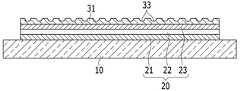
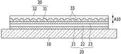
도 1을 참고하면, 유기 발광 표시 장치(100)는 기판(10)과, 기판(10) 위에 형성된 유기 발광 소자(20)와, 유기 발광 소자(20)를 덮으며 기판(10) 위에 형성된 봉지층(30)을 포함한다. 유기 발광 소자(20)는 제1 전극(21)과 발광층(22) 및 제2 전극(23)을 포함한다. 봉지층(30)은 유기막(31)과 무기막(32)을 포함하며, 유기막(31)과 무기막(32)의 경계에 혼합 영역(A10)이 위치한다.1, an organic light
기판(10)은 유리 기판 또는 플라스틱 기판일 수 있다. 기판(10)은 기계적 강도, 열적 안정성, 투명성, 표면 평탄성, 및 방수성이 우수한 유리 또는 플라스틱 소재로 형성될 수 있다. 기판(10) 위에는 수분과 산소 침투를 차단하는 베리어막(도시하지 않음)이 위치할 수 있다. 베리어막은 무기막과 유기막 중 어느 하나 또는 무기막과 유기막의 적층막으로 형성될 수 있다.The
기판(10) 위에 유기 발광 소자(20)가 위치한다. 유기 발광 소자(20)는 제1 전극(21)과 발광층(22) 및 제2 전극(23)의 적층 구조로 이루어진다. 제1 전극(21)과 제2 전극(23) 중 어느 하나는 정공 주입 전극으로 기능하고, 다른 하나는 전자 주입 전극으로 기능한다.The organic
제1 전극(21)과 제2 전극(23)은 투명 전극, 반투명 전극, 또는 반사 전극일 수 있다. 제1 전극(21)이 투명 전극이고 제2 전극(23)이 반사 전극일 때 발광층(22)의 빛은 제2 전극(23)에 의해 반사되고 제1 전극(21)과 기판(10)을 투과해 외부로 방출된다. 반대로 제1 전극(21)이 반사 전극이고 제2 전극(23)이 투명 전극일 때 발광층(22)의 빛은 제1 전극(21)에 의해 반사되고 제2 전극(23)과 봉지층(30)을 투과해 외부로 방출된다.The
제1 전극(21)과 제2 전극(23) 사이에는 발광층(22) 이외에도 정공 주입층, 정공 수송층, 전자 수송층, 및 전자 주입층 가운데 하나 이상의 층이 더 형성될 수 있다. 제1 전극(21)과 제2 전극(23)에 구동 전압이 인가되면, 발광층(22)으로 전자와 정공이 주입되고, 주입된 전자와 정공이 결합하여 여기자(exciton)를 생성하며, 여기자가 여기 상태로부터 기저 상태로 떨어질 때 발광이 이루어진다.In addition to the
실제 기판(10) 상의 표시부에는 복수의 유기 발광 소자가 위치한다. 각각의 유기 발광 소자는 박막 트랜지스터를 포함하는 구동 회로부에 연결되어 구동 회로부에 의해 발광이 제어된다. 도 1에서는 편의상 구동 회로부의 도시를 생략하였으며, 표시부에 위치하는 복수의 유기 발광 소자를 하나로 개략화하여 도시하였다.A plurality of organic light emitting elements are disposed on the display portion on the
봉지층(30)은 유기 발광 소자(20)를 밀봉시켜 외기의 수분과 산소로부터 유기 발광 소자(20)를 보호한다. 봉지층(30)은 복수의 유기막(31)과 복수의 무기막(32)을 포함하고, 유기막(31)과 무기막(32)이 하나씩 교대로 적층되어 봉지층(30)을 구성한다. 무기막(32)은 수분과 산소 침투를 방지하고, 유기막(31)은 무기막(32)의 스트레스를 완화시키며 무기막(32)의 미세 크랙 및 핀홀 등을 채우는 역할을 한다.The sealing
봉지층(30)의 내부에는 유기막(31)과 무기막(32)의 경계가 복수개로 존재한다. 이 경계들 중 적어도 하나의 경계에 유기막(31)을 이루는 유기물과 무기막(32)을 이루는 무기물이 봉지층(30)의 면 방향을 따라 혼재되어 위치하는 혼합 영역(A10)이 형성된다. 여기서, 봉지층(30)의 '면 방향'은 유기막(31) 또는 무기막(32)의 표면과 나란한 방향(도 1의 가로 방향)을 의미한다.In the inside of the
도 2는 도 1에 도시한 봉지층 가운데 유기막을 나타낸 평면도이고, 도 3은 도 1에 도시한 봉지층의 부분 확대도이다.Fig. 2 is a plan view showing an organic film among the encapsulation layers shown in Fig. 1, and Fig. 3 is a partially enlarged view of the encapsulation layer shown in Fig.
도 1 내지 도 3을 참고하면, 유기막(31)의 표면에는 복수의 홈부(33)가 형성된다. 복수의 홈부(33)는 서로간 거리를 두고 독립적으로 형성된다. 즉, 홈부(33)는 일 방향을 따라 길게 연속된 모양으로 형성되지 않고 미세한 점의 형태로 개별적으로 형성된다.Referring to Figs. 1 to 3, a plurality of
복수의 홈부(33)는 원형, 타원형, 다각형 등 여러 모양으로 형성될 수 있으며, 특정 모양으로 한정되지 않는다. 복수의 홈부(33) 중 어느 하나의 홈부(33)는 다른 하나의 홈부(33)와 크기, 모양, 깊이 중 적어도 하나가 다를 수 있다. 복수의 홈부(33)는 규칙적으로 배치되거나 정해진 규칙 없이 임의로 배치될 수 있다. 복수의 홈부(33)가 임의로 배치되는 경우에도 홈부(33) 사이의 거리는 정해진 편차를 벗어나지 않는다.The plurality of
무기막(32)은 유기막(31)에 형성된 복수의 홈부(33)를 채우며 유기막(31) 바로 위에 형성된다. 따라서 무기막(32)의 일부는 복수의 홈부(33)를 완전히 채우는 돌기의 형상을 가지며, 무기막(32)의 다른 일부는 일정한 두께를 유지하는 막의 형상을 가진다.The
봉지층(30)의 단면을 관찰할 때, 봉지층(30)은 유기물로만 이루어진 유기물 영역(A20)(도 3 참조)과, 유기물과 무기물이 혼재하는 혼합 영역(A10)과, 무기물로만 이루어진 무기물 영역(A30)으로 구분된다. 유기물 영역(A20)과 혼합 영역(A10) 및 무기물 영역(A30)은 봉지층(30)의 두께 방향(도 3의 세로 방향)을 따라 위치한다. 혼합 영역(A10)의 두께는 홈부(33)의 평균 깊이와 같을 수 있다.3), a mixed region A10 in which an organic material and an inorganic material are mixed, and a mixed region A10 in which the inorganic material is composed only of an inorganic material Area A30. The organic material region A20, the mixed region A10 and the inorganic material region A30 are located along the thickness direction of the sealing layer 30 (the longitudinal direction in Fig. 3). The thickness of the mixed region A10 may be equal to the average depth of the
봉지층(30)의 혼합 영역(A10)에서 유기막(31)을 이루는 유기물과 무기막(32)을 이루는 무기물은 봉지층(30)의 면 방향을 따라 혼재되어 위치한다. 따라서 적어도 두 개의 홈부(33)를 관통하는 봉지층(30)의 면 방향(도 3의 A선 참조)을 따라 유기물과 무기물은 하나씩 교대로 위치한다.The organic material constituting the
봉지층(30)에서 유기막(31)과 무기막(32)은 봉지층(30)의 두께 방향을 따라 하나씩 교대로 위치하고, 봉지층(30)의 면 방향 중 서로 교차하는 두 방향을 따라 유기물과 무기물이 교대로 위치한다. 서로 교차하는 두 방향은 서로 직교하는 두 방향(예를 들어 도 2의 가로 방향과 도 2의 세로 방향)일 수 있다. 따라서 봉지층(30)은 유기물과 무기물이 세 방향을 따라 번갈아 위치하는 3차원 교차 네트워크 구조를 가진다.The
만일 유기막과 무기막이 모두 일정한 두께로 형성되어 유기막과 무기막 사이에 혼합 영역이 존재하지 않으면, 유기막과 무기막이 뚜렷한 경계를 두고 분리되어 막 탈락 현상이 발생할 수 있다. 또한, 유기막과 무기막의 경계를 따라 외기에 포함된 수분과 산소가 봉지층의 내부로 침투하여 유기 발광 소자의 특성을 저하시킬 수 있다.If the organic film and the inorganic film are both formed to have a uniform thickness and the mixed region is not present between the organic film and the inorganic film, the organic film and the inorganic film may be separated with a clear boundary and the film may be detached. In addition, moisture and oxygen contained in the outside air may penetrate into the interior of the sealing layer along the boundary between the organic film and the inorganic film, thereby deteriorating the characteristics of the organic light emitting device.
그러나 본 실시예에서 봉지층(30)은 유기막(31)과 무기막(32)의 3차원 교차 네트워크 구조로 인해 유기막(31)과 무기막(32)의 경계를 복잡하게 엉키게 만든 효과를 발휘한다. 따라서 봉지층(30)은 유기막(31)과 무기막(32)의 결합력을 높여 막 탈락 현상을 방지할 수 있고, 유기막(31)과 무기막(32)의 경계를 따라 외기의 수분과 산소가 침투하는 것을 억제할 수 있다.However, in the present embodiment, the
홈부(33)의 크기(폭)는 1㎚ 내지 5㎛의 범위에 속할 수 있고, 홈부(33)의 깊이 또한 1㎚ 내지 5㎛의 범위에 속할 수 있다. 홈부(33)의 크기와 깊이가 1㎚ 미만인 경우 3차원 교차 네크워크 구조가 미약하게 형성되어 유기막(31)과 무기막(32)의 결합력을 높이는 효과가 적게 발휘될 수 있다. 홈부(33)의 크기와 깊이가 5㎛을 초과하면 다음에 설명하는 유기 발광 표시 장치의 제조 과정에서 식각 대상 입자들의 분산이 어려워질 수 있다. 홈부(33) 사이의 거리는 유기막(31)의 분산 조건 및 분산 밀도에 따라 다양하게 변화할 수 있다.The size (width) of the
또한, 유기막(31)과 무기막(32)은 거칠기를 가지므로 굴절률 변화를 일으켜 광 효율을 향상시킨다. 전면 발광형 유기 발광 표시 장치의 경우, 유기 발광 소자(20)에서 방출된 빛이 봉지층(30)을 투과할 때 유기막(31)과 무기막(32)의 경계면에서 내부 반사를 줄여 광 추출 효율을 높일 수 있다. 그리고 외광이 봉지층(30)에 입사할 때 유기막(31)과 무기막(32)의 경계면에서 외광을 굴절시키므로 외광 반사를 억제할 수 있다. 광 추출 효율은 화면의 휘도 향상을 의미하며, 외광 반사 억제는 화면의 콘트라스트 개선으로 이어진다.Further, since the
전술한 유기막(31)은 1.2 내지 2.0의 범위에 속하는 굴절률을 나타내며, 무기막(32)은 1.3 내지 2.2의 범위에 속하는 굴절률을 나타낸다. 광 추출 효율을 높이기 위해 유기막(31)과 무기막(32)의 굴절률 차이는 0.1 이상으로 설정되고, 유기막(31)과 무기막(32)의 굴절률 차이가 클수록 광 추출 효율을 높일 수 있다.The
유기막(31)은 아크릴계 수지, 메타크릴계 수지, 폴리이소프렌, 비닐계 수지, 에폭시계 수지, 우레탄계 수지, 셀룰로오스계 수지, 및 페릴렌계 수지 중 적어도 하나를 포함할 수 있다. 복수의 유기막(31)은 같은 물질을 포함하거나 서로 다른 물질을 포함할 수도 있다. 유기막(31)은 다양한 방법으로 그 표면에 복수의 홈부(33)를 형성할 수 있다. 구체적인 홈부(33) 형성 방법에 대해서는 후술한다.The
무기막(32)은 실리콘 질화물, 알루미늄 질화물, 지르코늄 질화물, 티타늄 질화물, 하프늄 질화물, 탄탈륨 질화물, 실리콘 산화물, 알루미늄 산화물, 티타늄 산화물, 주석 산화물, 세륨 산화물, 및 실리콘 산화질화물 중 적어도 하나를 포함할 수 있다. 복수의 무기막(32)은 같은 물질을 포함하거나 다른 물질을 포함할 수도 있다.The
도 1에서는 봉지층(30)이 세 개의 유기막(31)과 세 개의 무기막(32)을 포함하고, 유기막(31) 바로 위에 무기막(32)이 적층되는 경계마다 혼합 영역(A10)이 위치하는 경우를 예로 들어 도시하였다. 그러나 유기막(31)과 무기막(32)의 개수와 형성 위치 및 혼합 영역(A10)의 적층 개수는 도시한 예에 한정되지 않고 다양하게 변할 수 있다.1, the
한편, 유기막(31)에는 복수의 홈부(33)와 복수의 홀이 같이 형성되거나, 복수의 홈부(33) 대신 복수의 홀이 형성될 수도 있다. 도 4에서는 복수의 홀(34)이 유기막(31)에 형성된 경우를 예로 들어 도시하였다.On the other hand, a plurality of
이 경우 봉지층(30)의 단면을 관찰할 때, 봉지층(30)은 유기물과 무기물이 봉지층(30)의 면 방향을 따라 혼재되어 위치하는 혼합 영역(A10)과, 무기물로만 이루어진 무기물 영역(A30)으로 구분된다. 즉, 유기막(31)은 유기물 영역 없이 혼합 영역(A10)에서 무기막(32)과 함께 위치한다. 유기막(31)에 복수의 홀(34)이 형성된 경우에도 유기막(31)은 봉지층(30)의 평탄성을 유지시키고 스트레스를 완화하는 기능은 동일하게 유지한다. 유기막(31)에서 홀의 크기(폭)는 전술한 홈부와 동일하게 1㎚ 내지 5㎛의 범위에 속할 수 있다.In this case, when the cross-section of the
이하, 본 실시예에 따른 유기 발광 표시 장치의 제조 방법에 대해 설명한다.Hereinafter, a method of manufacturing the organic light emitting diode display according to the present embodiment will be described.
본 실시예에 따른 유기 발광 표시 장치(100)의 제조 방법은 기판(10) 위에 제1 전극(21)과 발광층(22) 및 제2 전극(23)을 포함하는 유기 발광 소자(20)를 형성하는 단계와, 유기 발광 소자(20) 위에 봉지층(30)을 형성하는 단계를 포함한다. 봉지층(30)을 형성하는 단계는, 유기물과 식각 대상 입자들을 포함하는 유기막(31)을 형성하는 제1 단계와, 유기막(31)에 포함된 식각 대상 입자들을 선택 식각하여 복수의 홈부(33)를 형성하는 제2 단계와, 유기막(31) 바로 위에 무기막(32)을 형성하여 복수의 홈부(33)를 무기물로 채우는 제3 단계를 포함한다.A method of manufacturing an
도 5a 내지 도 5c는 본 발명의 일 실시예에 따른 유기 발광 표시 장치의 제조 방법을 설명하기 위한 개략적인 단면도이다.5A to 5C are schematic cross-sectional views illustrating a method of manufacturing an organic light emitting display according to an embodiment of the present invention.
도 5a를 참고하면, 기판(10) 위에 유기 발광 소자(20)를 형성한다. 유기 발광 소자(20)는 제1 전극(21)과 발광층(22) 및 제2 전극(23)을 포함한다. 물론 기판(10)과 유기 발광 소자(20) 사이에 베리어막(도시하지 않음)이 위치할 수 있으며, 기판(10) 위에 박막 트랜지스터를 포함하는 구동 회로부(도시하지 않음)가 형성된다. 구동 회로부는 유기 발광 소자(20)와 연결되어 유기 발광 소자(20)의 구동을 제어한다.Referring to FIG. 5A, an organic
이어서 유기 발광 소자(20)를 덮도록 유기막(31)을 형성한다(제1 단계). 유기막(31)은 유기물(35)과 식각 대상 입자들(36)의 혼합물로 이루어진다. 유기막(31)은 통상의 성막 방법, 예를 들어 코팅 및 열처리, 진공 증착 등의 방법으로 형성될 수 있다.Then, the
유기물(35)과 식각 대상 입자들(36)은 특정 에천트에 대해 서로 다른 식각률을 보인다. 구체적으로, 특정 에천트에 대해 식각 대상 입자들(36)은 높은 식각률을 보이는 반면 유기물(35)은 낮은 식각률을 보인다. 이로써 유기막(31)이 특정 에천트에 노출되면 유기막(31) 중 유기물(35)은 남고 식각 대상 입자들(36)이 선택적으로 식각된다.The
식각 대상 입자들(36)의 크기는 형성하고자 하는 홈부(33)의 크기와 동일하며, 형성하고자 하는 홈부(33)의 밀도에 맞추어 유기물(35)에 대한 식각 대상 입자들(36)의 함량이 정해진다. 식각 대상 입자들(36)은 유기 콜로이드 입자들, 무기 콜로이드 입자들, 또는 금속 콜로이드 입자들, 또는 탄소 나노튜브일 수 있다.The size of the
유기 콜로이드 입자들은 폴리스티렌(polystyrene), 폴리메틸메타크릴레이트(polymethylmethacrylate), 및 폴리글리시딜메타크릴레이트(polyglycidylmethacrylate) 중 적어도 하나를 포함할 수 있다. 무기 콜로이드 입자들은 SiO2, TiO2, ZnO, 및 ZrO 중 적어도 하나를 포함할 수 있다. 금속 콜로이드 입자들은 Cu, Ag, Au, 및 Fe 중 적어도 하나를 포함할 수 있다.The organic colloid particles may comprise at least one of polystyrene, polymethylmethacrylate, and polyglycidylmethacrylate. Colloidal inorganic particles may include at least one of SiO2, TiO2, ZnO, and ZrO. The metal colloid particles may comprise at least one of Cu, Ag, Au, and Fe.
이러한 콜로이드 입자들은 10-5cm 내지 10-7cm의 크기를 가진다. 콜로이드 입자들은 분산성이나 정전기적 특성 등의 조절을 위해 다양한 기능기를 가질 수 있으며, 단량체(monomer), 이합체(dimer), 또는 삼량체(trimer) 등 다양한 형태로 존재할 수 있다.These colloidal particles have a size of 10-5 cm to 10-7 cm. The colloidal particles may have various functional groups for controlling the dispersibility and the electrostatic property, and may exist in various forms such as a monomer, a dimer, or a trimer.
식각 대상 입자들(36)은 유기물(35)에 고르게 섞여 분산된다. 유기물(35)과 식각 대상 입자들(36)을 고르게 혼합시키기 위해 초음파 장치 또는 분쇄기와 같은 기계적 장치가 사용될 수 있다.The particles to be etched 36 are dispersed evenly in the
도 5a와 도 5b를 참고하면, 유기막(31)에 포함된 식각 대상 입자들(36)을 선택 식각한다(제2 단계). 그러면 식각 대상 입자들(36)이 제거되면서 식각 대상 입자들(36)이 있던 자리에 복수의 홈부(33)가 형성된다. 선택 식각은 여러 방법으로 진행될 수 있으며, 예를 들어 플라즈마 에칭법이 사용될 수 있다.5A and 5B, the
플라즈마 에칭법은 플라즈마에 의해 활성화된 라디칼과 전자 등을 이용하여 식각하는 방법이다. 유기막(31)을 챔버 내부에서 증착하고 플라즈마 에칭법을 적용하는 경우, 투입 가스와 압력, 인가 전압 등의 공정 조건만을 변경하여 같은 챔버 내부에서 연속 공정으로 유기막(31)에 포함된 식각 대상 입자들(36)을 선택적으로 식각할 수 있다.Plasma etching is a method of etching using radicals and electrons activated by plasma. When the
제1 단계에서 식각 대상 입자들(36)이 고르게 분산되어 위치함에 따라, 홈부(33) 사이의 거리는 정해진 편차를 벗어나지 않는다. 한편, 유기막(31)에 포함된 식각 대상 입자들(36)의 크기 및 유기막(31)의 두께 등에 따라 선택 식각 후 유기막(31)에는 복수의 홈부(33)와 복수의 홀이 같이 형성되거나, 복수의 홈부(33) 대신 복수의 홀이 형성될 수도 있다.As the
제1 단계에서 유기물(35)로서 폴리메타크릴레이트 수지와 은(Ag) 콜로이드 입자들을 혼합하고, 제2 단계에서 플라즈마 에칭으로 은(Ag) 콜로이드 입자들을 선택 식각하는 과정을 거친 유기막의 주사전자현미경(SEM) 사진을 도 6에 나타내었다. 도 6의 (A), (B), (C)는 은(Ag) 콜로이드 입자들의 크기와 분산 밀도를 다르게 적용하여 완성된 여러 홈부를 나타내고 있다.In the first step, polymethacrylate resin and silver (Ag) colloid particles are mixed as the
도 6에 나타난 바와 같이, 제1 단계와 제2 단계를 거친 유기막은 그 표면에 복수의 홈부를 미세한 점의 형태로 독립적으로 형성하고 있음을 확인할 수 있다.As shown in FIG. 6, it can be seen that the organic film that has undergone the first and second steps independently forms a plurality of grooves on the surface thereof in the form of fine points.
도 5c를 참고하면, 유기막(31) 바로 위에 무기막(32)을 형성하여 복수의 홈부(33)를 무기물로 채운다(제3 단계). 무기막(32)은 증착, 스퍼터링 등의 방법으로 형성될 수 있다. 이로써 유기막(31)과 무기막(32) 사이에 유기물과 무기물이 봉지층(30)의 면 방향을 따라 혼재되어 위치하는 혼합 영역(A10)이 형성되고, 유기물과 무기물은 3차원 교차 네트워크 구조를 형성한다.Referring to FIG. 5C, the
전술한 제1 단계 내지 제3 단계를 한 번 이상 반복하여 복수의 유기막(31)과 복수의 무기막(32)을 포함하는 봉지층(30)을 형성한다(도 1 참조). 이러한 봉지층(30)을 구비한 본 실시예의 유기 발광 표시 장치(100)는 봉지층(30)의 막 탈락 현상을 예방하고, 유기 발광 소자(20)를 향한 수분과 산소 침투를 차단하여 밀봉 성능을 높이며, 내부 반사와 외광 반사를 줄여 표시 품질을 향상시킬 수 있다.The above-described first to third steps are repeated one or more times to form an
상기에서는 본 발명의 바람직한 실시예에 대하여 설명하였지만, 본 발명은 이에 한정되는 것이 아니고 특허청구범위와 발명의 상세한 설명 및 첨부한 도면의 범위 안에서 여러 가지로 변형하여 실시하는 것이 가능하고 이 또한 본 발명의 범위에 속하는 것은 당연하다.While the present invention has been described in connection with what is presently considered to be practical exemplary embodiments, it is to be understood that the invention is not limited to the disclosed embodiments, but, on the contrary, Of course.
100: 유기 발광 표시 장치10: 기판
20: 유기 발광 소자21: 제1 전극
22: 발광층23: 제2 전극
30: 봉지층31: 유기막
32: 유기막33: 홈부
34: 홀35: 유기물
36: 식각 대상 입자들100: organic light emitting display device 10: substrate
20: organic light emitting element 21: first electrode
22: light emitting layer 23: second electrode
30: sealing layer 31: organic film
32: organic film 33: groove
34: Hall 35: Organics
36: Particles to be etched
Claims (17)
Translated fromKorean상기 기판 위에 배치되며 제1 전극과 발광층 및 제2 전극을 포함하는 유기 발광 소자; 및
상기 유기 발광 소자를 덮으며 상기 기판 위에 배치된 봉지층
을 포함하고,
상기 봉지층은 상기 봉지층의 두께 방향을 따라 교대로 배치되는 복수의 유기막과 복수의 무기막을 포함하며,
상기 각 유기막 위에 적층된 상기 각 무기막 사이의 경계 모두에 복수의 홈부 또는 복수의 홀이 형성되고,
상기 복수의 홈부 또는 상기 복수의 홀은 상기 각 유기막에 서로간 거리를 두고 분리되어 독립적으로 배치되고,
상기 각 무기막은 상기 복수의 홈부 또는 상기 복수의 홀을 채우면서 상기 각 유기막 바로 위에 배치되는 유기 발광 표시 장치.Board;
An organic light emitting diode disposed on the substrate and including a first electrode, a light emitting layer, and a second electrode; And
A sealing layer covering the organic light emitting element and disposed on the substrate,
/ RTI >
Wherein the sealing layer comprises a plurality of organic films and a plurality of inorganic films arranged alternately along the thickness direction of the sealing layer,
A plurality of trenches or a plurality of holes are formed in all the boundaries between the respective inorganic films laminated on the respective organic films,
Wherein the plurality of trenches or the plurality of holes are separated and disposed independently of each other with a distance therebetween,
Wherein each of the inorganic films is disposed directly on the organic film while filling the plurality of trenches or the plurality of holes.
상기 유기막에서 상기 홈부의 폭은 1㎚ 내지 5㎛의 범위에 속하는 유기 발광 표시 장치.The method according to claim 1,
Wherein a width of the groove portion in the organic film falls within a range of 1 nm to 5 占 퐉.
상기 유기막에서 상기 홈부의 깊이는 1㎚ 내지 5㎛의 범위에 속하는 유기 발광 표시 장치.The method according to claim 1,
Wherein a depth of the groove portion in the organic film is in a range of 1 nm to 5 占 퐉.
상기 유기막에서 상기 홀의 크기는 1㎚ 내지 5㎛의 범위에 속하는 유기 발광 표시 장치.The method according to claim 1,
And the size of the holes in the organic layer is in the range of 1 nm to 5 占 퐉.
상기 유기막은 아크릴계 수지, 메타크릴계 수지, 폴리이소프렌, 비닐계 수지, 에폭시계 수지, 우레탄계 수지, 셀룰로오스계 수지, 및 페릴렌계 수지로 이루어진 군으로부터 선택된 적어도 하나의 물질을 포함하는 유기 발광 표시 장치.The method according to claim 1,
Wherein the organic film comprises at least one material selected from the group consisting of an acrylic resin, a methacrylic resin, a polyisoprene, a vinyl resin, an epoxy resin, a urethane resin, a cellulose resin, and a perylene resin.
상기 무기막은 실리콘 질화물, 알루미늄 질화물, 지르코늄 질화물, 티타늄 질화물, 하프늄 질화물, 탄탈륨 질화물, 실리콘 산화물, 알루미늄 산화물, 티타늄 산화물, 주석 산화물, 세륨 산화물, 및 실리콘 산화질화물로 이루어진 군으로부터 선택된 적어도 하나의 물질을 포함하는 유기 발광 표시 장치.The method according to claim 1,
Wherein the inorganic film comprises at least one material selected from the group consisting of silicon nitride, aluminum nitride, zirconium nitride, titanium nitride, hafnium nitride, tantalum nitride, silicon oxide, aluminum oxide, titanium oxide, tin oxide, cerium oxide, And the organic light emitting display device.
Priority Applications (2)
| Application Number | Priority Date | Filing Date | Title |
|---|---|---|---|
| KR1020110033395AKR101873476B1 (en) | 2011-04-11 | 2011-04-11 | Organic light emitting diode display and manufacturing method thereof |
| US13/298,118US9070889B2 (en) | 2011-04-11 | 2011-11-16 | OLED display having organic and inorganic encapsulation layers, and manufacturing method thereof |
Applications Claiming Priority (1)
| Application Number | Priority Date | Filing Date | Title |
|---|---|---|---|
| KR1020110033395AKR101873476B1 (en) | 2011-04-11 | 2011-04-11 | Organic light emitting diode display and manufacturing method thereof |
Publications (2)
| Publication Number | Publication Date |
|---|---|
| KR20120115840A KR20120115840A (en) | 2012-10-19 |
| KR101873476B1true KR101873476B1 (en) | 2018-07-03 |
Family
ID=46965400
Family Applications (1)
| Application Number | Title | Priority Date | Filing Date |
|---|---|---|---|
| KR1020110033395AActiveKR101873476B1 (en) | 2011-04-11 | 2011-04-11 | Organic light emitting diode display and manufacturing method thereof |
Country Status (2)
| Country | Link |
|---|---|
| US (1) | US9070889B2 (en) |
| KR (1) | KR101873476B1 (en) |
Families Citing this family (86)
| Publication number | Priority date | Publication date | Assignee | Title |
|---|---|---|---|---|
| KR101842586B1 (en)* | 2011-04-05 | 2018-03-28 | 삼성디스플레이 주식회사 | Organic light emitting diode display and manufacturing method thereof |
| KR101873476B1 (en) | 2011-04-11 | 2018-07-03 | 삼성디스플레이 주식회사 | Organic light emitting diode display and manufacturing method thereof |
| KR20140018548A (en)* | 2012-08-02 | 2014-02-13 | 삼성디스플레이 주식회사 | Organic light emitting display device with enhanced light efficiency and manufacturing method thereof |
| WO2014038158A1 (en)* | 2012-09-04 | 2014-03-13 | シャープ株式会社 | Organic electroluminescent display, and production method therefor |
| CN103811432B (en)* | 2012-11-12 | 2016-09-14 | 财团法人工业技术研究院 | Environment sensitive electronic element packaging body |
| CN103855320B (en)* | 2012-11-30 | 2016-12-21 | 海洋王照明科技股份有限公司 | A kind of organic electroluminescence device and preparation method thereof |
| TWI492374B (en)* | 2012-12-03 | 2015-07-11 | Au Optronics Corp | Electroluminescent display panel |
| KR101980771B1 (en)* | 2012-12-31 | 2019-05-21 | 엘지디스플레이 주식회사 | Organic light emitting display and method of fabricating the same |
| KR101991100B1 (en)* | 2013-01-09 | 2019-06-20 | 삼성디스플레이 주식회사 | Organic light emitting diode display |
| KR102047922B1 (en)* | 2013-02-07 | 2019-11-25 | 삼성디스플레이 주식회사 | Flexible substrate, method for manufacturing flexible substrate, flexible display device, and method for flexible display device |
| US9831468B2 (en) | 2013-02-14 | 2017-11-28 | Samsung Display Co., Ltd. | Organic electroluminescent device having thin film encapsulation structure and method of fabricating the same |
| KR101996436B1 (en) | 2013-02-14 | 2019-07-05 | 삼성디스플레이 주식회사 | Organic light emitting device having thin film encapsulation and method for fabricating the same |
| CN104037351A (en)* | 2013-03-07 | 2014-09-10 | 海洋王照明科技股份有限公司 | Organic light emission diode and preparation method thereof |
| KR102044923B1 (en)* | 2013-04-15 | 2019-11-15 | 삼성디스플레이 주식회사 | Organic light emitting display device and manufacturing method thereof |
| JP6203383B2 (en)* | 2013-05-21 | 2017-09-27 | エルジー・ケム・リミテッド | Sealing film and organic electronic device sealing method using the same |
| CN104752631B (en)* | 2013-12-26 | 2017-02-22 | 昆山工研院新型平板显示技术中心有限公司 | Organic light-emitting device packaging structure and packaging method |
| CN103887446A (en)* | 2014-03-10 | 2014-06-25 | 京东方科技集团股份有限公司 | Encapsulation structure for OLED device and encapsulation method and lighting device of OLED device |
| KR102245771B1 (en)* | 2014-07-29 | 2021-04-28 | 삼성디스플레이 주식회사 | Organic light emitting diode display |
| KR102250048B1 (en)* | 2014-09-16 | 2021-05-11 | 삼성디스플레이 주식회사 | Organic light emitting display device |
| KR101871549B1 (en)* | 2014-10-29 | 2018-07-03 | 삼성에스디아이 주식회사 | Sealant composition for display, organic protective layer comprising the same, and display apparatus comprising the same |
| KR102442909B1 (en)* | 2015-03-02 | 2022-09-15 | 삼성디스플레이 주식회사 | Polarizer and display device compring the same |
| CN104900812A (en) | 2015-04-23 | 2015-09-09 | 京东方科技集团股份有限公司 | Film packaging structure, manufacture method thereof and display device |
| CN105118927A (en)* | 2015-07-01 | 2015-12-02 | 深圳市华星光电技术有限公司 | OLED film packaging structure, packaging method and display device |
| CN105140417A (en) | 2015-08-20 | 2015-12-09 | 京东方科技集团股份有限公司 | Organic light-emitting diode device, fabrication method and display device |
| CN105047165A (en) | 2015-08-28 | 2015-11-11 | 深圳市华星光电技术有限公司 | RGBW-based drive circuit and flat panel display |
| US10074826B2 (en)* | 2015-10-06 | 2018-09-11 | Samsung Display Co., Ltd. | Display apparatus and method of manufacturing the same |
| KR102384292B1 (en)* | 2015-10-06 | 2022-04-08 | 삼성디스플레이 주식회사 | Display apparatus and method for manufacturing the same |
| CN105206763B (en)* | 2015-10-21 | 2018-01-23 | 京东方科技集团股份有限公司 | Flexible display and its manufacture method |
| KR102446425B1 (en) | 2015-11-17 | 2022-09-23 | 삼성디스플레이 주식회사 | Display device and method of manufacturing display device |
| CN105552246A (en)* | 2015-12-07 | 2016-05-04 | 上海天马微电子有限公司 | Flexible display device and manufacturing method thereof |
| KR102470258B1 (en)* | 2015-12-22 | 2022-11-24 | 삼성디스플레이 주식회사 | Display apparatus and method for manufacturing the same |
| CN105449121B (en) | 2016-01-13 | 2017-08-25 | 京东方科技集团股份有限公司 | Method for packing, OLED packagings and the display device of OLED |
| CN105679800B (en) | 2016-01-27 | 2019-08-13 | 京东方科技集团股份有限公司 | OLED display screen and preparation method thereof, display equipment |
| CN105810845B (en)* | 2016-05-17 | 2018-05-25 | 武汉华星光电技术有限公司 | OLED device packaging structure, OLED device and display screen |
| CN105870355A (en)* | 2016-05-27 | 2016-08-17 | 京东方科技集团股份有限公司 | Flexible OLED device and preparation method thereof |
| CN105938873A (en) | 2016-07-01 | 2016-09-14 | 武汉华星光电技术有限公司 | Flexible display apparatus and manufacture method thereof |
| KR102586045B1 (en)* | 2016-07-12 | 2023-10-10 | 삼성디스플레이 주식회사 | Display apparatus and manufacturing method thereof |
| CN106129267B (en)* | 2016-08-02 | 2018-01-12 | 武汉华星光电技术有限公司 | OLED thin-film packing structures and preparation method thereof |
| CN106328826B (en)* | 2016-10-24 | 2019-04-30 | 武汉华星光电技术有限公司 | OLED display and preparation method thereof |
| CN106450031B (en)* | 2016-11-07 | 2019-02-26 | 武汉华星光电技术有限公司 | Thin film encapsulated OLED device and thin film encapsulation method of OLED device |
| CN106410062A (en)* | 2016-11-07 | 2017-02-15 | 武汉华星光电技术有限公司 | A kind of encapsulation layer and encapsulation device |
| CN106711347A (en)* | 2016-12-28 | 2017-05-24 | 武汉华星光电技术有限公司 | OLED device and substrate thereof |
| CN108630822B (en)* | 2017-03-24 | 2020-06-30 | 京东方科技集团股份有限公司 | Component of a top-emitting OLED device and top-emitting OLED device |
| CN109427995B (en)* | 2017-08-31 | 2020-04-17 | 昆山工研院新型平板显示技术中心有限公司 | Flexible display device |
| CN107658388B (en)* | 2017-09-27 | 2020-03-06 | 京东方科技集团股份有限公司 | OLED display panel, preparation method and display device thereof |
| KR102453920B1 (en)* | 2017-11-08 | 2022-10-13 | 삼성디스플레이 주식회사 | Organic light emitting display apparatus and the manufacturing method thereof |
| CN108962023B (en)* | 2017-11-30 | 2021-04-16 | Tcl科技集团股份有限公司 | Flexible display device and preparation method thereof |
| CN110085740B (en)* | 2018-01-25 | 2022-01-11 | 绵阳京东方光电科技有限公司 | Flexible substrate, manufacturing method thereof, panel and electronic device |
| CN108565360A (en)* | 2018-04-10 | 2018-09-21 | 深圳市华星光电技术有限公司 | A kind of OLED display and preparation method thereof |
| CN108666440A (en)* | 2018-04-23 | 2018-10-16 | 深圳市华星光电技术有限公司 | A kind of OLED display and preparation method thereof |
| CN108470854A (en)* | 2018-04-25 | 2018-08-31 | 深圳市华星光电技术有限公司 | WOLED display panels and preparation method thereof |
| CN110492015B (en)* | 2018-05-15 | 2022-03-01 | 上海和辉光电股份有限公司 | Thin film packaging structure and preparation method |
| CN108511630B (en)* | 2018-05-31 | 2019-12-03 | 云谷(固安)科技有限公司 | Display panel and display device |
| CN108899438A (en)* | 2018-06-21 | 2018-11-27 | 武汉华星光电半导体显示技术有限公司 | Display panel and preparation method thereof |
| CN108878680A (en)* | 2018-06-26 | 2018-11-23 | 武汉华星光电半导体显示技术有限公司 | A kind of encapsulation type display device and display panel |
| CN109065760B (en)* | 2018-08-22 | 2021-04-27 | 京东方科技集团股份有限公司 | Packaging structure, packaging method and display device |
| CN109309176B (en)* | 2018-08-30 | 2020-09-01 | 武汉华星光电半导体显示技术有限公司 | Preparation method of display substrate and display substrate |
| CN109192878B (en)* | 2018-08-30 | 2019-11-26 | 武汉华星光电半导体显示技术有限公司 | Flexible OLED display panel |
| CN109273505B (en)* | 2018-09-28 | 2020-08-04 | 霸州市云谷电子科技有限公司 | Display device, flexible O L ED display panel and manufacturing method thereof |
| CN109273507B (en)* | 2018-09-30 | 2020-06-05 | 霸州市云谷电子科技有限公司 | a display panel |
| CN109791999B (en)* | 2018-11-01 | 2022-12-09 | 京东方科技集团股份有限公司 | Display panel, manufacturing method thereof, and display device |
| CN208753371U (en)* | 2018-11-02 | 2019-04-16 | 京东方科技集团股份有限公司 | Flexible display panel and display device |
| CN109523922B (en)* | 2018-12-14 | 2021-08-17 | 云谷(固安)科技有限公司 | Flexible module, display panel and display device |
| JP6814230B2 (en)* | 2019-01-11 | 2021-01-13 | 株式会社Joled | Light emitting panel, light emitting device and electronic equipment |
| CN109817830A (en)* | 2019-01-31 | 2019-05-28 | 武汉华星光电半导体显示技术有限公司 | Display panel and display device |
| US20200286742A1 (en)* | 2019-03-06 | 2020-09-10 | Kateeva, Inc. | Remote plasma etch using inkjet printed etch mask |
| CN110444116B (en)* | 2019-07-16 | 2021-07-06 | 武汉华星光电半导体显示技术有限公司 | Flexible substrate and preparation method thereof |
| CN110518143A (en)* | 2019-08-19 | 2019-11-29 | 武汉华星光电半导体显示技术有限公司 | OLED display panel and preparation method thereof |
| CN110518145B (en)* | 2019-08-28 | 2022-02-22 | 云谷(固安)科技有限公司 | Thin film packaging structure, preparation method thereof and display panel |
| CN110690358A (en)* | 2019-09-05 | 2020-01-14 | 武汉华星光电半导体显示技术有限公司 | Display panel, display device and manufacturing method of display panel |
| CN110635014B (en)* | 2019-09-25 | 2022-01-25 | 昆山工研院新型平板显示技术中心有限公司 | Flexible cover plate and display panel |
| CN110993826B (en)* | 2019-12-19 | 2021-12-03 | 武汉华星光电半导体显示技术有限公司 | OLED display panel, display panel and display device |
| KR20210079898A (en)* | 2019-12-20 | 2021-06-30 | 엘지디스플레이 주식회사 | Display device |
| CN110993828A (en)* | 2020-01-03 | 2020-04-10 | 武汉华星光电半导体显示技术有限公司 | OLED display panel |
| CN111430569A (en)* | 2020-03-31 | 2020-07-17 | 武汉华星光电半导体显示技术有限公司 | Encapsulation layer and preparation method thereof |
| CN111613735B (en)* | 2020-06-03 | 2024-04-19 | 京东方科技集团股份有限公司 | Light-emitting device and method for manufacturing the same, display device or lighting device |
| CN112017539B (en)* | 2020-08-07 | 2022-11-08 | 武汉华星光电半导体显示技术有限公司 | Packaging film, manufacturing method thereof, display panel and electronic equipment |
| CN112151693A (en)* | 2020-09-27 | 2020-12-29 | 京东方科技集团股份有限公司 | Packaging structure, display panel and display device |
| CN114335402A (en)* | 2020-10-12 | 2022-04-12 | 上海和辉光电股份有限公司 | Flexible substrate bubble repairing method, flexible substrate and flexible display panel |
| CN112162424A (en)* | 2020-10-15 | 2021-01-01 | 武汉华星光电半导体显示技术有限公司 | Display device and method for manufacturing the same |
| CN114420857B (en)* | 2020-10-28 | 2025-07-11 | 京东方科技集团股份有限公司 | Light emitting device and manufacturing method thereof, and display device |
| CN112802978A (en)* | 2021-01-08 | 2021-05-14 | 深圳市华星光电半导体显示技术有限公司 | Display panel, preparation method thereof and display device |
| CN113299696B (en)* | 2021-05-06 | 2024-03-05 | 武汉华星光电技术有限公司 | Curved surface display panel and preparation method thereof |
| CN115458699A (en)* | 2021-06-08 | 2022-12-09 | Tcl科技集团股份有限公司 | Packaging film, packaging structure of photoelectric device and packaging method |
| CN115918297A (en)* | 2021-06-16 | 2023-04-04 | 京东方科技集团股份有限公司 | Display panel and display device |
| CN118660473A (en)* | 2024-08-21 | 2024-09-17 | 江苏汇显显示技术有限公司 | Solar cell module and preparation method thereof and solar cell |
Citations (2)
| Publication number | Priority date | Publication date | Assignee | Title |
|---|---|---|---|---|
| JP2001274293A (en)* | 2000-03-24 | 2001-10-05 | Hitachi Chem Co Ltd | Semiconductor device and substrate for semiconductor element mounting |
| JP2004258380A (en)* | 2003-02-26 | 2004-09-16 | Toshiba Corp | Display device and method for manufacturing transparent substrate for display device |
Family Cites Families (45)
| Publication number | Priority date | Publication date | Assignee | Title |
|---|---|---|---|---|
| KR100251091B1 (en) | 1996-11-29 | 2000-04-15 | 구본준 | Manufacturing method of liquid crystal display device and liquid crystal display device manufactured by the manufacturing method |
| US6413645B1 (en) | 2000-04-20 | 2002-07-02 | Battelle Memorial Institute | Ultrabarrier substrates |
| KR100897771B1 (en) | 2001-03-13 | 2009-05-15 | 도쿄엘렉트론가부시키가이샤 | Film forming method and film forming apparatus |
| KR100387723B1 (en) | 2001-04-11 | 2003-06-18 | 주식회사 엘리아테크 | OELD with a multi-sealing layer and a manufacturing method thereof |
| KR100421480B1 (en) | 2001-06-01 | 2004-03-12 | 엘지.필립스 엘시디 주식회사 | Method for Processing Surface of Organic Isolation Film and Method of Fabricating Thin Film Transistor Substate using the same |
| US20040229051A1 (en) | 2003-05-15 | 2004-11-18 | General Electric Company | Multilayer coating package on flexible substrates for electro-optical devices |
| SG142140A1 (en) | 2003-06-27 | 2008-05-28 | Semiconductor Energy Lab | Display device and method of manufacturing thereof |
| US6969634B2 (en) | 2003-09-24 | 2005-11-29 | Lucent Technologies Inc. | Semiconductor layers with roughness patterning |
| KR100992141B1 (en) | 2003-11-19 | 2010-11-04 | 삼성전자주식회사 | Organic light emitting display |
| KR100611148B1 (en) | 2003-11-25 | 2006-08-09 | 삼성에스디아이 주식회사 | Thin film transistor, manufacturing method thereof and organic light emitting device using same |
| KR100553765B1 (en) | 2004-06-10 | 2006-02-20 | 삼성에스디아이 주식회사 | Organic electroluminescent display and manufacturing method thereof |
| US20080157065A1 (en) | 2004-08-03 | 2008-07-03 | Ahila Krishnamoorthy | Compositions, layers and films for optoelectronic devices, methods of production and uses thereof |
| KR20070049211A (en) | 2004-09-30 | 2007-05-10 | 가부시끼가이샤 도시바 | Organic Electroluminescent Display |
| JP4511440B2 (en) | 2004-10-05 | 2010-07-28 | 三星モバイルディスプレイ株式會社 | ORGANIC LIGHT EMITTING ELEMENT AND METHOD FOR PRODUCING ORGANIC LIGHT EMITTING ELEMENT |
| KR101085443B1 (en) | 2004-10-08 | 2011-11-21 | 삼성전자주식회사 | Display board with thin film protective layer and thin film protective layer |
| JP4578958B2 (en) | 2004-12-16 | 2010-11-10 | シャープ株式会社 | Liquid crystal display |
| US7563625B2 (en) | 2005-01-11 | 2009-07-21 | SemiLEDs Optoelectronics Co., Ltd. | Method of making light-emitting diodes (LEDs) with improved light extraction by roughening |
| JP4696796B2 (en) | 2005-09-07 | 2011-06-08 | 株式会社豊田自動織機 | Method for manufacturing organic electroluminescence device |
| KR100695169B1 (en) | 2006-01-11 | 2007-03-14 | 삼성전자주식회사 | Flat Panel Display |
| KR101326135B1 (en) | 2006-11-27 | 2013-11-07 | 삼성디스플레이 주식회사 | Organic light emitting display and manufacturing method thereof |
| KR101368725B1 (en) | 2007-03-26 | 2014-03-04 | 삼성디스플레이 주식회사 | Organic Light Emitting display Device And Manufacturing Method of The Same |
| KR100875099B1 (en)* | 2007-06-05 | 2008-12-19 | 삼성모바일디스플레이주식회사 | Organic light emitting device and method for manufacturing same |
| WO2009039212A1 (en) | 2007-09-21 | 2009-03-26 | Bridgelux, Inc. | Light-emitting diode chip with high extraction and method for manufacturing the same |
| EP2091096A1 (en)* | 2008-02-15 | 2009-08-19 | Nederlandse Organisatie voor toegepast-natuurwetenschappelijk Onderzoek TNO | Encapsulated electronic device and method of manufacturing |
| US7781780B2 (en) | 2008-03-31 | 2010-08-24 | Bridgelux, Inc. | Light emitting diodes with smooth surface for reflective electrode |
| KR101572259B1 (en) | 2008-09-03 | 2015-11-27 | 엘지디스플레이 주식회사 | Manufacturing Method of Organic Light Emitting Display |
| FR2936651B1 (en) | 2008-09-30 | 2011-04-08 | Commissariat Energie Atomique | ORGANIC OPTOELECTRONIC DEVICE AND METHOD OF ENCAPSULATION |
| US8405233B2 (en) | 2009-01-14 | 2013-03-26 | Dow Corning Corporation | Flexible barrier film, method of forming same, and organic electronic device including same |
| JP5424738B2 (en) | 2009-06-23 | 2014-02-26 | キヤノン株式会社 | Display device |
| KR20110054841A (en) | 2009-11-18 | 2011-05-25 | 삼성모바일디스플레이주식회사 | Organic light emitting display and manufacturing method thereof |
| KR20110058123A (en) | 2009-11-25 | 2011-06-01 | 삼성모바일디스플레이주식회사 | Organic light emitting display and manufacturing method thereof |
| US8236615B2 (en) | 2009-11-25 | 2012-08-07 | International Business Machines Corporation | Passivation layer surface topography modifications for improved integrity in packaged assemblies |
| KR101097330B1 (en) | 2010-01-19 | 2011-12-23 | 삼성모바일디스플레이주식회사 | Organic light emitting display device and method for manufacturing the same |
| CA2793041C (en) | 2010-04-20 | 2014-12-23 | Mylan Group | Substrate for lithographic printing plate |
| KR101671793B1 (en) | 2010-07-01 | 2016-11-04 | 삼성전자주식회사 | Semiconductor Light Emitting Diode and Method of manufacturing thereof |
| KR101764272B1 (en) | 2010-12-02 | 2017-08-16 | 삼성디스플레이 주식회사 | Organic light emitting display device and manufacturing method thereof |
| KR20120065049A (en)* | 2010-12-10 | 2012-06-20 | 삼성모바일디스플레이주식회사 | Organic light emitting diode display apparatus and manufacturing method thereof |
| US9224983B2 (en) | 2010-12-20 | 2015-12-29 | Samsung Electronics Co., Ltd. | Substrate for surface light emitting device and method of manufacturing the substrate, surface light emitting device, lighting apparatus, and backlight including the same |
| CN103370806A (en)* | 2011-02-07 | 2013-10-23 | 应用材料公司 | Method for encapsulating an organic light emitting diode |
| KR101844557B1 (en)* | 2011-02-08 | 2018-04-02 | 어플라이드 머티어리얼스, 인코포레이티드 | Method for hybrid encapsulation of an organic light emitting diode |
| KR101873476B1 (en) | 2011-04-11 | 2018-07-03 | 삼성디스플레이 주식회사 | Organic light emitting diode display and manufacturing method thereof |
| US8907560B2 (en) | 2011-05-12 | 2014-12-09 | Universal Display Corporation | Dynamic OLED lighting |
| US8466484B2 (en) | 2011-06-21 | 2013-06-18 | Kateeva, Inc. | Materials and methods for organic light-emitting device microcavity |
| KR20130006936A (en)* | 2011-06-27 | 2013-01-18 | 삼성디스플레이 주식회사 | Organic light emitting diode display |
| US9312511B2 (en) | 2012-03-16 | 2016-04-12 | Universal Display Corporation | Edge barrier film for electronic devices |
- 2011
- 2011-04-11KRKR1020110033395Apatent/KR101873476B1/enactiveActive
- 2011-11-16USUS13/298,118patent/US9070889B2/enactiveActive
Patent Citations (2)
| Publication number | Priority date | Publication date | Assignee | Title |
|---|---|---|---|---|
| JP2001274293A (en)* | 2000-03-24 | 2001-10-05 | Hitachi Chem Co Ltd | Semiconductor device and substrate for semiconductor element mounting |
| JP2004258380A (en)* | 2003-02-26 | 2004-09-16 | Toshiba Corp | Display device and method for manufacturing transparent substrate for display device |
Also Published As
| Publication number | Publication date |
|---|---|
| US9070889B2 (en) | 2015-06-30 |
| US20120256202A1 (en) | 2012-10-11 |
| KR20120115840A (en) | 2012-10-19 |
Similar Documents
| Publication | Publication Date | Title |
|---|---|---|
| KR101873476B1 (en) | Organic light emitting diode display and manufacturing method thereof | |
| KR101842586B1 (en) | Organic light emitting diode display and manufacturing method thereof | |
| CN109410758B (en) | transparent display device | |
| KR102159792B1 (en) | Flexible display device and manufacturing method thereof | |
| TWI814238B (en) | Organic light emitting diode device and display device including the same | |
| KR101809659B1 (en) | Organic light emitting diode display and method for manufacturing the same | |
| CN101794810B (en) | Organic light-emitting display apparatus | |
| EP2143156B1 (en) | Light-emitting device having improved light output and method of forming | |
| TWI492436B (en) | Flexible display panel | |
| WO2019242114A1 (en) | Display panel and manufacturing method therefor | |
| JP2009501426A (en) | OLED devices with improved efficiency and durability | |
| CN112670332A (en) | Pixel unit, manufacturing method thereof and display device | |
| CN106450036B (en) | OLED encapsulating structure, OLED device and display screen | |
| WO2018082168A1 (en) | Thin-film encapsulated oled device and thin film encapsulation method for oled device | |
| CN108598108A (en) | Flexible panel and its manufacturing method and display device | |
| CN110335958A (en) | Organic light-emitting display panel, manufacturing method thereof, and packaging film | |
| CN105449121A (en) | Packaging method of OLED device, OLED device, and display apparatus | |
| US20130140982A1 (en) | Organic light emitting display device and manufacturing method thereof | |
| JP4838857B2 (en) | Silicon light emitting device | |
| US20240090250A1 (en) | Light emitting element, display device, and method for producing light-emitting element | |
| CN217009217U (en) | Quantum dot protection structure and light-color conversion structure | |
| KR101631729B1 (en) | Method for producing an organic radiation-emitting component and organic radiation-emitting component | |
| JP2024509004A (en) | Display panel and display device | |
| KR102454468B1 (en) | Signal control unit for an organic light emitting diode display device, method of manufacturing the same, and organic light emitting diode including the same | |
| KR20140108434A (en) | Light extraction layer for light emitting apparatus and method of forming the light extraction layer |
Legal Events
| Date | Code | Title | Description |
|---|---|---|---|
| PA0109 | Patent application | Patent event code:PA01091R01D Comment text:Patent Application Patent event date:20110411 | |
| N231 | Notification of change of applicant | ||
| PN2301 | Change of applicant | Patent event date:20120726 Comment text:Notification of Change of Applicant Patent event code:PN23011R01D | |
| PG1501 | Laying open of application | ||
| A201 | Request for examination | ||
| PA0201 | Request for examination | Patent event code:PA02012R01D Patent event date:20160411 Comment text:Request for Examination of Application Patent event code:PA02011R01I Patent event date:20110411 Comment text:Patent Application | |
| E902 | Notification of reason for refusal | ||
| PE0902 | Notice of grounds for rejection | Comment text:Notification of reason for refusal Patent event date:20171025 Patent event code:PE09021S01D | |
| AMND | Amendment | ||
| E601 | Decision to refuse application | ||
| PE0601 | Decision on rejection of patent | Patent event date:20180214 Comment text:Decision to Refuse Application Patent event code:PE06012S01D Patent event date:20171025 Comment text:Notification of reason for refusal Patent event code:PE06011S01I | |
| AMND | Amendment | ||
| PX0901 | Re-examination | Patent event code:PX09011S01I Patent event date:20180214 Comment text:Decision to Refuse Application Patent event code:PX09012R01I Patent event date:20171226 Comment text:Amendment to Specification, etc. | |
| PX0701 | Decision of registration after re-examination | Patent event date:20180329 Comment text:Decision to Grant Registration Patent event code:PX07013S01D Patent event date:20180321 Comment text:Amendment to Specification, etc. Patent event code:PX07012R01I Patent event date:20180214 Comment text:Decision to Refuse Application Patent event code:PX07011S01I Patent event date:20171226 Comment text:Amendment to Specification, etc. Patent event code:PX07012R01I | |
| X701 | Decision to grant (after re-examination) | ||
| GRNT | Written decision to grant | ||
| PR0701 | Registration of establishment | Comment text:Registration of Establishment Patent event date:20180626 Patent event code:PR07011E01D | |
| PR1002 | Payment of registration fee | Payment date:20180626 End annual number:3 Start annual number:1 | |
| PG1601 | Publication of registration | ||
| PR1001 | Payment of annual fee | Payment date:20210601 Start annual number:4 End annual number:4 | |
| PR1001 | Payment of annual fee | Payment date:20220523 Start annual number:5 End annual number:5 | |
| PR1001 | Payment of annual fee | Payment date:20230524 Start annual number:6 End annual number:6 | |
| PR1001 | Payment of annual fee | Payment date:20240523 Start annual number:7 End annual number:7 |