KR101871221B1 - Multi-culvature cathether and medical device for surgery - Google Patents
Multi-culvature cathether and medical device for surgeryDownload PDFInfo
- Publication number
- KR101871221B1 KR101871221B1KR1020170021831AKR20170021831AKR101871221B1KR 101871221 B1KR101871221 B1KR 101871221B1KR 1020170021831 AKR1020170021831 AKR 1020170021831AKR 20170021831 AKR20170021831 AKR 20170021831AKR 101871221 B1KR101871221 B1KR 101871221B1
- Authority
- KR
- South Korea
- Prior art keywords
- elastic body
- wire
- catheter
- curvature
- section
- Prior art date
- Legal status (The legal status is an assumption and is not a legal conclusion. Google has not performed a legal analysis and makes no representation as to the accuracy of the status listed.)
- Active
Links
- 238000001356surgical procedureMethods0.000titledescription5
- 238000005452bendingMethods0.000claimsdescription50
- 238000000034methodMethods0.000claimsdescription19
- 210000004204blood vesselAnatomy0.000description4
- 230000033001locomotionEffects0.000description4
- 230000002526effect on cardiovascular systemEffects0.000description3
- 206010003119arrhythmiaDiseases0.000description2
- 210000004351coronary vesselAnatomy0.000description2
- 230000008878couplingEffects0.000description2
- 238000010168coupling processMethods0.000description2
- 238000005859coupling reactionMethods0.000description2
- 230000000694effectsEffects0.000description2
- 238000004519manufacturing processMethods0.000description2
- 208000010496Heart ArrestDiseases0.000description1
- 206010000891acute myocardial infarctionDiseases0.000description1
- 239000000853adhesiveSubstances0.000description1
- 230000001070adhesive effectEffects0.000description1
- 238000002399angioplastyMethods0.000description1
- 230000006793arrhythmiaEffects0.000description1
- 230000002490cerebral effectEffects0.000description1
- 229920001971elastomerPolymers0.000description1
- 239000000806elastomerSubstances0.000description1
- 238000001839endoscopyMethods0.000description1
- 238000003780insertionMethods0.000description1
- 230000037431insertionEffects0.000description1
- 239000000463materialSubstances0.000description1
- 230000000149penetrating effectEffects0.000description1
- 238000002560therapeutic procedureMethods0.000description1
- 210000003708urethraAnatomy0.000description1
Images


Classifications
- A—HUMAN NECESSITIES
- A61—MEDICAL OR VETERINARY SCIENCE; HYGIENE
- A61M—DEVICES FOR INTRODUCING MEDIA INTO, OR ONTO, THE BODY; DEVICES FOR TRANSDUCING BODY MEDIA OR FOR TAKING MEDIA FROM THE BODY; DEVICES FOR PRODUCING OR ENDING SLEEP OR STUPOR
- A61M25/00—Catheters; Hollow probes
- A61M25/01—Introducing, guiding, advancing, emplacing or holding catheters
- A61M25/0105—Steering means as part of the catheter or advancing means; Markers for positioning
- A61M25/0133—Tip steering devices
- A61M25/0147—Tip steering devices with movable mechanical means, e.g. pull wires
- A—HUMAN NECESSITIES
- A61—MEDICAL OR VETERINARY SCIENCE; HYGIENE
- A61M—DEVICES FOR INTRODUCING MEDIA INTO, OR ONTO, THE BODY; DEVICES FOR TRANSDUCING BODY MEDIA OR FOR TAKING MEDIA FROM THE BODY; DEVICES FOR PRODUCING OR ENDING SLEEP OR STUPOR
- A61M25/00—Catheters; Hollow probes
- A61M25/01—Introducing, guiding, advancing, emplacing or holding catheters
- A61M25/0105—Steering means as part of the catheter or advancing means; Markers for positioning
- A61M25/0133—Tip steering devices
- A61B5/04—
- A—HUMAN NECESSITIES
- A61—MEDICAL OR VETERINARY SCIENCE; HYGIENE
- A61B—DIAGNOSIS; SURGERY; IDENTIFICATION
- A61B5/00—Measuring for diagnostic purposes; Identification of persons
- A61B5/24—Detecting, measuring or recording bioelectric or biomagnetic signals of the body or parts thereof
- A—HUMAN NECESSITIES
- A61—MEDICAL OR VETERINARY SCIENCE; HYGIENE
- A61M—DEVICES FOR INTRODUCING MEDIA INTO, OR ONTO, THE BODY; DEVICES FOR TRANSDUCING BODY MEDIA OR FOR TAKING MEDIA FROM THE BODY; DEVICES FOR PRODUCING OR ENDING SLEEP OR STUPOR
- A61M25/00—Catheters; Hollow probes
- A61M25/0067—Catheters; Hollow probes characterised by the distal end, e.g. tips
- A61M25/0074—Dynamic characteristics of the catheter tip, e.g. openable, closable, expandable or deformable
- A—HUMAN NECESSITIES
- A61—MEDICAL OR VETERINARY SCIENCE; HYGIENE
- A61M—DEVICES FOR INTRODUCING MEDIA INTO, OR ONTO, THE BODY; DEVICES FOR TRANSDUCING BODY MEDIA OR FOR TAKING MEDIA FROM THE BODY; DEVICES FOR PRODUCING OR ENDING SLEEP OR STUPOR
- A61M25/00—Catheters; Hollow probes
- A61M25/01—Introducing, guiding, advancing, emplacing or holding catheters
- A61M25/0105—Steering means as part of the catheter or advancing means; Markers for positioning
- A61M25/0133—Tip steering devices
- A61M25/0144—Tip steering devices having flexible regions as a result of inner reinforcement means, e.g. struts or rods
- A—HUMAN NECESSITIES
- A61—MEDICAL OR VETERINARY SCIENCE; HYGIENE
- A61N—ELECTROTHERAPY; MAGNETOTHERAPY; RADIATION THERAPY; ULTRASOUND THERAPY
- A61N1/00—Electrotherapy; Circuits therefor
- A61N1/02—Details
- A61N1/04—Electrodes
- A61N1/05—Electrodes for implantation or insertion into the body, e.g. heart electrode
- A—HUMAN NECESSITIES
- A61—MEDICAL OR VETERINARY SCIENCE; HYGIENE
- A61B—DIAGNOSIS; SURGERY; IDENTIFICATION
- A61B5/00—Measuring for diagnostic purposes; Identification of persons
- A61B5/24—Detecting, measuring or recording bioelectric or biomagnetic signals of the body or parts thereof
- A61B5/25—Bioelectric electrodes therefor
- A61B5/279—Bioelectric electrodes therefor specially adapted for particular uses
- A61B5/28—Bioelectric electrodes therefor specially adapted for particular uses for electrocardiography [ECG]
- A61B5/283—Invasive
- A—HUMAN NECESSITIES
- A61—MEDICAL OR VETERINARY SCIENCE; HYGIENE
- A61M—DEVICES FOR INTRODUCING MEDIA INTO, OR ONTO, THE BODY; DEVICES FOR TRANSDUCING BODY MEDIA OR FOR TAKING MEDIA FROM THE BODY; DEVICES FOR PRODUCING OR ENDING SLEEP OR STUPOR
- A61M25/00—Catheters; Hollow probes
- A61M25/0067—Catheters; Hollow probes characterised by the distal end, e.g. tips
- A61M25/0082—Catheter tip comprising a tool
- A61M2025/0095—Catheter tip comprising a tool being one or more needles protruding from the distal tip and which are not used for injection nor for electro-stimulation, e.g. for fixation purposes
- A—HUMAN NECESSITIES
- A61—MEDICAL OR VETERINARY SCIENCE; HYGIENE
- A61M—DEVICES FOR INTRODUCING MEDIA INTO, OR ONTO, THE BODY; DEVICES FOR TRANSDUCING BODY MEDIA OR FOR TAKING MEDIA FROM THE BODY; DEVICES FOR PRODUCING OR ENDING SLEEP OR STUPOR
- A61M25/00—Catheters; Hollow probes
- A61M25/01—Introducing, guiding, advancing, emplacing or holding catheters
- A61M25/0105—Steering means as part of the catheter or advancing means; Markers for positioning
- A61M25/0133—Tip steering devices
- A61M2025/0161—Tip steering devices wherein the distal tips have two or more deflection regions
- A—HUMAN NECESSITIES
- A61—MEDICAL OR VETERINARY SCIENCE; HYGIENE
- A61M—DEVICES FOR INTRODUCING MEDIA INTO, OR ONTO, THE BODY; DEVICES FOR TRANSDUCING BODY MEDIA OR FOR TAKING MEDIA FROM THE BODY; DEVICES FOR PRODUCING OR ENDING SLEEP OR STUPOR
- A61M25/00—Catheters; Hollow probes
- A61M25/01—Introducing, guiding, advancing, emplacing or holding catheters
- A61M25/0105—Steering means as part of the catheter or advancing means; Markers for positioning
- A61M25/0133—Tip steering devices
- A61M2025/0163—Looped catheters
- A—HUMAN NECESSITIES
- A61—MEDICAL OR VETERINARY SCIENCE; HYGIENE
- A61M—DEVICES FOR INTRODUCING MEDIA INTO, OR ONTO, THE BODY; DEVICES FOR TRANSDUCING BODY MEDIA OR FOR TAKING MEDIA FROM THE BODY; DEVICES FOR PRODUCING OR ENDING SLEEP OR STUPOR
- A61M25/00—Catheters; Hollow probes
- A61M25/01—Introducing, guiding, advancing, emplacing or holding catheters
- A61M25/0105—Steering means as part of the catheter or advancing means; Markers for positioning
- A61M2025/0166—Sensors, electrodes or the like for guiding the catheter to a target zone, e.g. image guided or magnetically guided
- A—HUMAN NECESSITIES
- A61—MEDICAL OR VETERINARY SCIENCE; HYGIENE
- A61M—DEVICES FOR INTRODUCING MEDIA INTO, OR ONTO, THE BODY; DEVICES FOR TRANSDUCING BODY MEDIA OR FOR TAKING MEDIA FROM THE BODY; DEVICES FOR PRODUCING OR ENDING SLEEP OR STUPOR
- A61M2230/00—Measuring parameters of the user
- A61M2230/08—Other bio-electrical signals
- A61M2230/10—Electroencephalographic signals
- A—HUMAN NECESSITIES
- A61—MEDICAL OR VETERINARY SCIENCE; HYGIENE
- A61M—DEVICES FOR INTRODUCING MEDIA INTO, OR ONTO, THE BODY; DEVICES FOR TRANSDUCING BODY MEDIA OR FOR TAKING MEDIA FROM THE BODY; DEVICES FOR PRODUCING OR ENDING SLEEP OR STUPOR
- A61M25/00—Catheters; Hollow probes
- A61M25/0021—Catheters; Hollow probes characterised by the form of the tubing
- A61M25/0041—Catheters; Hollow probes characterised by the form of the tubing pre-formed, e.g. specially adapted to fit with the anatomy of body channels
- A—HUMAN NECESSITIES
- A61—MEDICAL OR VETERINARY SCIENCE; HYGIENE
- A61M—DEVICES FOR INTRODUCING MEDIA INTO, OR ONTO, THE BODY; DEVICES FOR TRANSDUCING BODY MEDIA OR FOR TAKING MEDIA FROM THE BODY; DEVICES FOR PRODUCING OR ENDING SLEEP OR STUPOR
- A61M25/00—Catheters; Hollow probes
- A61M25/01—Introducing, guiding, advancing, emplacing or holding catheters
- A61M25/0105—Steering means as part of the catheter or advancing means; Markers for positioning
- A61M25/0133—Tip steering devices
- A61M25/0136—Handles therefor
- A—HUMAN NECESSITIES
- A61—MEDICAL OR VETERINARY SCIENCE; HYGIENE
- A61M—DEVICES FOR INTRODUCING MEDIA INTO, OR ONTO, THE BODY; DEVICES FOR TRANSDUCING BODY MEDIA OR FOR TAKING MEDIA FROM THE BODY; DEVICES FOR PRODUCING OR ENDING SLEEP OR STUPOR
- A61M25/00—Catheters; Hollow probes
- A61M25/01—Introducing, guiding, advancing, emplacing or holding catheters
- A61M25/0105—Steering means as part of the catheter or advancing means; Markers for positioning
- A61M25/0133—Tip steering devices
- A61M25/0152—Tip steering devices with pre-shaped mechanisms, e.g. pre-shaped stylets or pre-shaped outer tubes
Landscapes
- Health & Medical Sciences (AREA)
- Life Sciences & Earth Sciences (AREA)
- Engineering & Computer Science (AREA)
- Animal Behavior & Ethology (AREA)
- Veterinary Medicine (AREA)
- Public Health (AREA)
- Biomedical Technology (AREA)
- Heart & Thoracic Surgery (AREA)
- General Health & Medical Sciences (AREA)
- Biophysics (AREA)
- Pulmonology (AREA)
- Hematology (AREA)
- Anesthesiology (AREA)
- Mechanical Engineering (AREA)
- Cardiology (AREA)
- Nuclear Medicine, Radiotherapy & Molecular Imaging (AREA)
- Radiology & Medical Imaging (AREA)
- Physics & Mathematics (AREA)
- Pathology (AREA)
- Medical Informatics (AREA)
- Molecular Biology (AREA)
- Surgery (AREA)
- Media Introduction/Drainage Providing Device (AREA)
Abstract
Translated fromKoreanDescription
Translated fromKorean본 발명은 다곡률 카테터 및 수술용 의료장치에 관한 것으로, 보다 자세하게는 와이어 조절을 통해 굽힘을 형성하는 카테터와 이를 이용한 수술용 의료장치에 관한 것이다.BACKGROUND OF THE INVENTION 1. Field of the Invention The present invention relates to a multi-curvature catheter and a surgical medical device, and more particularly, to a catheter that forms a bend through wire adjustment and a surgical medical device using the catheter.
카테터는 직접 신체에 삽입되는 의료용 수단을 포괄적으로 지칭하는 기구로써, 혈관 주사용, 관상동맥 확장용, 요도 삽입용, 기도삽입용, 복강경 수술용 카테터 등과 같이 신체 삽입을 위한 다양한 카테터들이 사용되고 있다.A catheter is a device collectively referred to as a medical device that is directly inserted into a body. Various catheters are used for insertion of the body, such as a blood vessel, a coronary artery, a urethral, a pneumatic, or a laparoscopic surgical catheter.
이러한 카테터는 혈관, 요도, 기도 등을 통해 정밀하게 삽입되어야 하며, 그 조정이 미세하게 이루어져야 하기 때문에 정밀하게 제작되어야 하며, 시술 편의성, 정확성 및 안정성의 관점에서 많은 개선이 요구된다. 또한, 뇌혈관, 관상동맥의 폐색으로 인한 뇌졸중, 급성 심근경색, 심장마비와 같은 심혈관계 치료 분야에서 다양한 카테터의 개발과 이를 이용한 혈관성형 시술법이 개발되고 있다.Such a catheter must be precisely inserted through a blood vessel, urethra, airway, etc., and must be finely adjusted because of its fine adjustment, and many improvements are required from the viewpoint of convenience of operation, accuracy, and stability. In addition, various catheters have been developed in the field of cardiovascular therapy such as cerebral blood vessels, stroke due to occlusion of coronary arteries, acute myocardial infarction, and cardiac arrest, and angioplasty procedures using the same have been developed.
최근에는 원위단부를 굴곡시킴으로써 체강으로의 진입방향이 조작 가능한 카테터가 제공되고 있다.Recently, a catheter capable of manipulating the direction of entry into the body cavity by bending the distal end thereof has been provided.
예를 들어, 공개특허공보 제10-2011-0139698호(공개일자: 2011.12.29)(이하, "선행기술문헌"이라 함)에는 카테터 및 카테터의 제조방법을 게시하고 있다. 상기 선행기술문헌은 카테터 본체(관상 본체)에 소정의 강성을 갖는 관통 와이어(조작선)가 마련되며 이 조작선을 밀어 넣음으로써 관상 본체의 원위단이 굴곡이 이루어지는 카테터를 보여주고 있다. 이와 같이, 최근의 카테터는 조작선에 의해 카테터 원위단의 조정이 가능하여 카테터 자체를 체강 내에 진입이 가능하다.For example, Published Japanese Patent Application No. 10-2011-0139698 (published on December 29, 2011) (hereinafter referred to as "prior art document") discloses a method of manufacturing a catheter and a catheter. The prior art document shows a catheter in which a penetrating wire (operating line) having a predetermined rigidity is provided in a catheter body (tubular body), and the distal end of the tubular body is bent by pushing the operating line. In this way, in recent catheters, the distal end of the catheter can be adjusted by the operating line so that the catheter itself can enter the body cavity.
본 발명은, 카테터를 구부리는 방향에 따라 벤딩섹션의 휘어지기 시작하는 지점을 상이하도록 하여 휘어지는 곡률을 상이하게 형성하는, 다곡률 카테터 및 수술용 의료장치을 제공하고자 한다.The present invention seeks to provide a multi-curvature catheter and surgical medical device that differentiate in curvature by bending the bending section such that the bending section is at a different point in the bending direction of the catheter.
본 발명이 해결하고자 하는 과제들은 이상에서 언급된 과제로 제한되지 않으며, 언급되지 않은 또 다른 과제들은 아래의 기재로부터 통상의 기술자에게 명확하게 이해될 수 있을 것이다.The problems to be solved by the present invention are not limited to the above-mentioned problems, and other problems which are not mentioned can be clearly understood by those skilled in the art from the following description.
본 발명의 일실시예에 따른 다곡률 카테터는, 상기 카테터의 말단에 위치하며, 평평하게 형성되는 제1탄성체; 상기 제1탄성체에 연결되며, 일정 곡률반경을 가지며 제1방향을 향해 만곡되게 돌출 형성된 제2탄성체; 상기 제1탄성체의 일면에 연결되어, 당김조작에 따라 상기 카테터의 제1방향으로의 굽힘을 형성하는 제1와이어; 상기 제1탄성체의 상기 제1와이어가 연결된 면의 반대면에 연결되어, 당김조작에 따라 상기 카테터의 제2방향으로의 굽힘을 형성는 제2와이어; 및 상기 제1탄성체, 상기 제2탄성체, 제1와이어 및 제2와이어를 포함하는 튜브;를 포함한다.A multi-curvature catheter according to an embodiment of the present invention includes: a first elastic body positioned at a distal end of the catheter and formed to be flat; A second elastic body connected to the first elastic body, the second elastic body having a predetermined radius of curvature and curvedly protruding toward the first direction; A first wire connected to one surface of the first elastic body to form a bend in the first direction of the catheter according to a pulling operation; A second wire connected to an opposite surface of the first elastic body opposite to the surface to which the first wire is connected so as to form a bend in the second direction of the catheter in accordance with the pulling operation; And a tube including the first elastic body, the second elastic body, the first wire, and the second wire.
본 발명의 다른 일실시예에 따른 다곡률 카테터는, 상기 카테터의 말단에 위치하며, 제1곡률반경을 가지며 제1방향을 향해 만곡되게 돌출 형성된 제1탄성체; 상기 제1탄성체에 연결되며, 제2곡률반경을 가지며 제2방향을 향해 만곡되게 돌출 형성된 제2탄성체; 상기 제1탄성체의 일면에 연결되어, 당김조작에 따라 상기 카테터의 제1방향으로의 굽힘을 형성하는 제1와이어; 상기 제1탄성체의 상기 제1와이어가 연결된 면의 반대면에 연결되어, 당김조작에 따라 상기 카테터의 제2방향으로의 굽힘을 형성는 제2와이어; 및 상기 제1탄성체, 상기 제2탄성체, 제1와이어 및 제2와이어를 포함하는 튜브;를 포함한다.According to another aspect of the present invention, there is provided a multi-curvature catheter comprising: a first elastic body, positioned at an end of the catheter, having a first radius of curvature and curvedly protruding toward a first direction; A second elastic body connected to the first elastic body, the second elastic body having a second radius of curvature and curvedly protruding toward the second direction; A first wire connected to one surface of the first elastic body to form a bend in the first direction of the catheter according to a pulling operation; A second wire connected to an opposite surface of the first elastic body opposite to the surface to which the first wire is connected so as to form a bend in the second direction of the catheter in accordance with the pulling operation; And a tube including the first elastic body, the second elastic body, the first wire, and the second wire.
또한, 다른 일실시예는, 상기 튜브 내를 관통하는 내시경을 더 포함한다.Still another embodiment further includes an endoscope passing through the tube.
또한, 다른 일실시예는, 상기 제2탄성체에 연결되며, 평평하거나 특정한 제3곡률반경을 가지며 상기 제1방향을 향해 만곡되게 돌출 형성된 제3탄성체; 상기 제3탄성체에 연결되며, 특정한 제4곡률반경을 가지며 상기 제1방향 또는 상기 제2방향을 향해 만곡되게 돌출 형성된 제4탄성체; 상기 제3탄성체의 일면에 연결되는 제3와이어; 및 상기 제3탄성체의 상기 제3와이어가 연결된 면의 반대면에 연결되는 제4와이어;를 더 포함한다.According to another embodiment of the present invention, a third elastic body connected to the second elastic body and having a flat or specific third radius of curvature and curvedly protruding toward the first direction; A fourth elastic body connected to the third elastic body, the fourth elastic body having a specific fourth radius of curvature and being curved so as to protrude toward the first direction or the second direction; A third wire connected to one surface of the third elastic body; And a fourth wire connected to an opposite surface of the surface of the third elastic body to which the third wire is connected.
또한, 다른 일실시예는, 상기 제1와이어와 상기 제2와이어를 제어하여 제1방향 또는 제2방향으로의 휘어짐을 형성하는 조작부;를 더 포함한다.According to another embodiment of the present invention, there is further provided an operation unit for controlling the first wire and the second wire to form a warp in the first direction or the second direction.
또한, 다른 일실시예는, 상기 카테터의 외부로 노출되는 전극을 포함하고, 상기 제1와이어 또는 상기 제2와이어는 상기 전극에 연결되는 전선으로 형성된다.Further, another embodiment includes an electrode exposed to the outside of the catheter, wherein the first wire or the second wire is formed by a wire connected to the electrode.
또한, 다른 일실시예는, 상기 제1탄성체 및 상기 제2탄성체는, 상기 제1와이어가 연결되는 면인 제1면 및 상기 제2와이어가 연결되는 면인 제2면에 각각 상호 대응되는 개수의 풀리를 구비하며, 상기 제1와이어는 상기 제1탄성체와 상기 제2탄성체의 상기 제1면에 구비된 풀리에 번갈아 감기고, 상기 제2와이어는 상기 제1탄성체와 상기 제2탄성체의 상기 제2면에 구비된 풀리에 번갈아 감기는 것을 특징으로 한다.According to another embodiment of the present invention, the first elastic body and the second elastic body are provided on a first surface which is a surface to which the first wire is connected and a second surface which is a surface to which the second wire is connected, Wherein the first wire is alternately wound on the pulleys provided on the first surface of the first elastic body and the second elastic body and the second wire is wound on the second surface of the first elastic body and the second elastic body, And the pulleys are wound alternately.
본 발명의 또 다른 일실시예에 따른 수술용 의료장치는, 카테터; 및 구동장치;를 포함하며, 상기 카테터는, 상기 카테터의 말단에 위치하며, 평평하게 형성되는 제1탄성체; 상기 제1탄성체에 연결되며, 특정한 곡률반경을 가지며 제1방향을 향해 만곡되게 돌출 형성된 제2탄성체; 상기 제1탄성체의 일면에 연결되는 제1와이어; 상기 제1탄성체의 상기 제1와이어가 연결된 면의 반대면에 연결되는 제2와이어; 상기 제1탄성체, 상기 제2탄성체, 제1와이어 및 제2와이어를 포함하는 튜브; 및 상기 카테터의 외부로 노출되는 전극;을 포함하고, 상기 구동장치는, 상기 카테터 외부에 구비되며, 상기 제1와이어와 상기 제2와이어를 당기는 정도를 제어하여 제1방향 또는 제2방향으로의 휘어짐을 형성한다.A surgical medical device according to another embodiment of the present invention includes: a catheter; And a driving device, wherein the catheter includes: a first elastic body positioned at a distal end of the catheter and formed to be flat; A second elastic body connected to the first elastic body and having a specific radius of curvature and being formed so as to protrude curved toward the first direction; A first wire connected to one surface of the first elastic body; A second wire connected to a surface of the first elastic body opposite to a surface to which the first wire is connected; A tube including the first elastic body, the second elastic body, the first wire, and the second wire; And an electrode exposed to the outside of the catheter, wherein the driving device is provided outside the catheter, and the degree of pulling of the first wire and the second wire is controlled, Thereby forming a warp.
본 발명의 또 다른 일실시예에 따른 수술용 의료장치는, 카테터; 및 구동장치;를 포함하며, 상기 카테터는, 상기 카테터의 말단에 위치하며, 제1곡률반경을 가지며 제1방향을 향해 만곡되게 돌출 형성된 제1탄성체;상기 제1탄성체에 연결되며, 제2곡률반경을 가지며 제2방향을 향해 만곡되게 돌출 형성된 제2탄성체; 상기 제1탄성체의 일면에 연결되는 제1와이어; 상기 제1탄성체의 상기 제1와이어가 연결된 면의 반대면에 연결되는 제2와이어; 상기 제1탄성체, 상기 제2탄성체, 제1와이어 및 제2와이어를 포함하는 튜브; 및 상기 카테터의 외부로 노출되는 전극;을 포함하고, 상기 구동장치는, 상기 카테터 외부에 구비되며, 상기 제1와이어와 상기 제2와이어를 당기는 정도를 제어하여 제1방향 또는 제2방향으로의 휘어짐을 형성한다.A surgical medical device according to another embodiment of the present invention includes: a catheter; The catheter having a first curvature and a second curvature, the first curvature having a first radius of curvature and being curved toward a first direction, the curvature being connected to the first curvature, A second elastic body having a radius and protruding curved toward a second direction; A first wire connected to one surface of the first elastic body; A second wire connected to a surface of the first elastic body opposite to a surface to which the first wire is connected; A tube including the first elastic body, the second elastic body, the first wire, and the second wire; And an electrode exposed to the outside of the catheter, wherein the driving device is provided outside the catheter, and the degree of pulling of the first wire and the second wire is controlled, Thereby forming a warp.
또한, 다른 실시예는, 상기 제2탄성체에 연결되며, 평평하게 형성되거나 특정한 제3곡률반경을 가지며 상기 제1방향을 향해 만곡되게 돌출 형성된 제3탄성체; 상기 제3탄성체에 연결되며, 특정한 제4곡률반경을 가지며 상기 제1방향 또는 상기 제2방향을 향해 만곡되게 돌출 형성된 제4탄성체; 상기 제3탄성체의 일면에 연결되는 제3와이어; 및 상기 제3탄성체의 상기 제3와이어가 연결된 면의 반대면에 연결되는 제4와이어;를 더 포함하고, 상기 구동장치는, 상기 제1와이어, 상기 제2와이어, 상기 제3와이어 및 상기 제4와이어를 제어하는 것을 특징으로 한다.Another embodiment of the present invention includes a third elastic body connected to the second elastic body and formed flat or having a specific third radius of curvature and being curvedly protruded toward the first direction; A fourth elastic body connected to the third elastic body, the fourth elastic body having a specific fourth radius of curvature and being curved so as to protrude toward the first direction or the second direction; A third wire connected to one surface of the third elastic body; And a fourth wire connected to a surface of the third elastic body opposite to a surface to which the third wire is connected, and the driving device further includes a second wire, a second wire, a third wire, Four wires are controlled.
또한, 다른 일실시예는, 상기 제1와이어 또는 상기 제2와이어는 상기 전극에 연결되는 전선으로 형성된다.In another embodiment, the first wire or the second wire is formed of a wire connected to the electrode.
상기와 같은 본 발명에 따르면, 아래와 같은 다양한 효과들을 가진다.According to the present invention as described above, the following various effects are obtained.
첫째, 카테터의 양방향으로 휘어지는 벤딩섹션 내의 지점을 상이하게 하여 곡률을 상이하게 형성함에 따라, 의료진은 신체부위 내의 특정지점에 접근하기 용이한 휘어짐 형태를 선택적으로 이용할 수 있다. 특히, 카테터가 진입한 경로(예를 들어, 심장혈관)와 가까운 영역에 카테터의 말단이 도달하기 위해, 벤딩섹션의 중간지점부터 휘어짐(즉, 제2탄성체는 휘어지지 않은 상태에서 제1탄성체만 휘어져서 짧은 구간이 휘어짐)에 따라 시술 부위 내에서 카테터 조작을 위한 와이어 제어가 간편해질 수 있다.First, by forming different curvatures by differentiating points in the bi-directionally bent bending section of the catheter, the medical practitioner can selectively use a warping form that is easy to approach a specific point in the body part. In particular, in order for the distal end of the catheter to reach the region close to the path (for example, a cardiovascular vessel) in which the catheter has entered, it is necessary to warp from the middle point of the bending section (i.e. the second elastic body The bending of the short section causes the wire control for catheter manipulation within the procedure site to be simplified.
둘째, 탄성체 조합을 다양하게 함에 따라 다양한 구부러짐을 형성할 수 있다. 제1탄성체와 제2탄성체의 길이, 제1탄성체와 제2탄성체의 곡률 차이, 제1탄성체와 제2탄성체의 휘어진 방향 차이 등을 통해 카테터의 움직임을 다양하게 형성할 수 있다.Second, various flexures can be formed by varying the elastic combination. The movement of the catheter can be variously formed through the lengths of the first and second elastic bodies, the difference in curvature of the first and second elastic bodies, and the difference in the direction in which the first and second elastic bodies are bent.
셋째, 단위벤딩섹션을 여러 개 연결함에 따라, 다양한 카테터 모션을 구현할 수 있다.Third, by connecting multiple unit bending sections, various catheter motions can be implemented.
도 1은 본 발명의 일실시예에 따른 다곡률카테터의 예시도면이다.
도 2 및 도 3은 본 발명의 일실시예에 따른 평면 형태의 제1탄성체를 포함하는 밴딩섹션의 예시도면이다.
도 4는 본 발명의 일실시예에 따른 휘어진 방향이 반대인 제1탄성체와 제2탄성체를 연결한 밴팅섹션의 예시도면이다.
도 5는 본 발명의 일실시예에 따른 제1방향(즉, 제2탄성체의 볼록한 제1면 방향)으로 당겨지는 경우의 밴딩섹션의 예시도면이다.
도 6은 본 발명의 일실시예에 따른 제2방향(즉, 제2탄성체의 오목한 제2면 방향)으로 당겨지는 경우의 밴딩섹션의 예시도면이다.
도 7은 본 발명의 일실시예에 따른 제3탄성체 및 제4탄성체를 더 포함하는 밴딩섹션의 예시도면이다.
도 8은 보 발명의 일실시예에 따른 튜브 표면에 전극을 구비한 예시도면이다.
도 9는 본 발명의 일실시예에 따른 다곡률 카테터의 정면도이다.
도 10은 본 발명의 일실시예에 따른 와이어가 풀리에 감긴 다곡률 카테터의 예시도면이다.
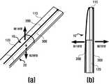
도 11(a)는 본 발명의 일실시예에 따라 밴딩섹션이 제1방향 및 제2방향으로 휘어지는 경우의 휘어지는 형태 차이를 나타내는 예시도면이다.
도 11(b)는 본 발명의 일실시예를 심장부정맥 수술에 이용하는 예시도면이다.1 is an exemplary illustration of a multi-curvature catheter in accordance with an embodiment of the present invention.
FIGS. 2 and 3 are exemplary views of a bending section including a first elastic body in plan view according to an embodiment of the present invention. FIG.
4 is an exemplary view of a bending section connecting a first elastic body and a second elastic body which are opposite in the warping direction according to an embodiment of the present invention.
5 is an exemplary view of a bending section when pulled in a first direction (i.e., a convex first surface direction of a second elastic body) according to an embodiment of the present invention.
6 is an exemplary view of a bending section when pulled in a second direction (i.e., a second concave second face direction of the second elastomer) according to an embodiment of the present invention.
7 is an exemplary view of a bending section further including a third elastic body and a fourth elastic body according to an embodiment of the present invention.
8 is an exemplary view showing an electrode provided on a surface of a tube according to an embodiment of the present invention.
9 is a front view of a multi-curvature catheter according to an embodiment of the present invention.
10 is an exemplary view of a multi-curvature catheter in which a wire is wound onto a pulley, according to an embodiment of the invention.
11 (a) is an exemplary view showing a bent shape difference when the banding section is bent in the first direction and the second direction according to an embodiment of the present invention.
Fig. 11 (b) is an example of using an embodiment of the present invention for cardiac arrhythmia surgery.
이하, 첨부된 도면을 참조하여 본 발명의 바람직한 실시예를 상세히 설명한다. 본 발명의 이점 및 특징, 그리고 그것들을 달성하는 방법은 첨부되는 도면과 함께 상세하게 후술되어 있는 실시예들을 참조하면 명확해질 것이다. 그러나 본 발명은 이하에서 게시되는 실시예들에 한정되는 것이 아니라 서로 다른 다양한 형태로 구현될 수 있으며, 단지 본 실시예들은 본 발명의 게시가 완전하도록 하고, 본 발명이 속하는 기술분야에서 통상의 지식을 가진 자에게 발명의 범주를 완전하게 알려주기 위해 제공되는 것이며, 본 발명은 청구항의 범주에 의해 정의될 뿐이다. 명세서 전체에 걸쳐 동일 참조 부호는 동일 구성 요소를 지칭한다.Hereinafter, preferred embodiments of the present invention will be described in detail with reference to the accompanying drawings. BRIEF DESCRIPTION OF THE DRAWINGS The advantages and features of the present invention, and the manner of achieving them, will be apparent from and elucidated with reference to the embodiments described hereinafter in conjunction with the accompanying drawings. The present invention may, however, be embodied in many different forms and should not be construed as limited to the embodiments set forth herein. Rather, these embodiments are provided so that this disclosure will be thorough and complete, and will fully convey the scope of the invention to those skilled in the art. To fully disclose the scope of the invention to those skilled in the art, and the invention is only defined by the scope of the claims. Like reference numerals refer to like elements throughout the specification.
다른 정의가 없다면, 본 명세서에서 사용되는 모든 용어(기술 및 과학적 용어를 포함)는 본 발명이 속하는 기술분야에서 통상의 지식을 가진 자에게 공통적으로 이해될 수 있는 의미로 사용될 수 있을 것이다. 또 일반적으로 사용되는 사전에 정의되어 있는 용어들은 명백하게 특별히 정의되어 있지 않는 한 이상적으로 또는 과도하게 해석되지 않는다.Unless defined otherwise, all terms (including technical and scientific terms) used herein may be used in a sense commonly understood by one of ordinary skill in the art to which this invention belongs. Also, commonly used predefined terms are not ideally or excessively interpreted unless explicitly defined otherwise.
본 명세서에서 사용된 용어는 실시예들을 설명하기 위한 것이며 본 발명을 제한하고자 하는 것은 아니다. 본 명세서에서, 단수형은 문구에서 특별히 언급하지 않는 한 복수형도 포함한다. 명세서에서 사용되는 "포함한다(comprises)" 및/또는 "포함하는(comprising)"은 언급된 구성요소 외에 하나 이상의 다른 구성요소의 존재 또는 추가를 배제하지 않는다.The terminology used herein is for the purpose of illustrating embodiments and is not intended to be limiting of the present invention. In the present specification, the singular form includes plural forms unless otherwise specified in the specification. The terms " comprises "and / or" comprising "used in the specification do not exclude the presence or addition of one or more other elements in addition to the stated element.
도 1은 본 발명의 일실시예에 따른 다곡률 카테터의 예시도면이다.1 is an exemplary illustration of a multi-curvature catheter in accordance with an embodiment of the present invention.
도 1을 참조하면, 본 발명의 일실시예에 따른 다곡률 카테터는, 밴딩섹션(Bending Section)(100); 제1와이어(200); 제2와이어(300); 및 튜브(600);를 포함한다.Referring to FIG. 1, a multi-curvature catheter according to an embodiment of the present invention includes a
상기 밴딩섹션(100)은 카테터가 신체 내부에 삽입된 후 휘어지도록 하는 구성에 해당한다. 상기 밴딩섹션은 특정한 폭과 두께를 가져서, 후술되는 바와 같이, 밴딩섹션의 말단에 연결되는 하나 이상의 와이어 조작에 의해 휘어진다. 즉, 도 5 및 도 6에서와 같이, 상기 밴딩섹션은 와이어가 당겨짐에 의해 넓은 폭을 가지는 제1면(10)과 제2면(20) 방향으로 휘어진다. 상기 밴딩섹션은 복수의 탄성체가 연결되어 형성된다.The
일실시예로, 상기 밴딩섹션은, 제1탄성체(110) 및 제2탄성체(120)가 연결되어 형성된다. 제1탄성체(110)는 상기 카테터의 말단에 위치하며, 평평하게 형성되거나(도 2 및 도 3(a) 참조), 상기 카테터 진행방향에 수직한 방향으로 특정한 곡률로 휘어진 형태로 형성(즉, 일정 곡률반경을 가지며 특정한 방향을 향해 만곡되게 돌출 형성)될 수 있다(도 4 참조). 제2탄성체(120)는 상기 제1탄성체(110)에 연결되며, 상기 카테터 진행방향에 수직한 방향으로 특정한 곡률로 휘어진 형태로 형성(즉, 특정한 곡률반경을 가지며 특정한 방향을 향해 만곡되게 돌출 형성)된다. 후술되는 바와 같이, 제1탄성체(110)와 제2탄성체(120)의 조합은, 평평한 형태와 만곡된 형태의 조합이 될 수 있고, 상이한 곡률 및 만곡방향 조건을 가진 형태의 조합이 될 수 있다.In one embodiment, the banding section is formed by connecting a first
제1탄성체(110)와 제2탄성체(120)는 각각의 말단면이 접촉되도록 결합될 수 있고(도 3(b) 참조), 제1탄성체(110) 및 제2탄성체(120)가 겹쳐지도록 결합될 수 있다. 제1탄성체(110) 및 제2탄성체(120)를 결합하는 방식으로는 접착제를 사용하거나 결합부로 연결부위를 감싸는 방식 등 다양한 방식이 적용될 수 있다.The first
제1탄성체(110) 및 제2탄성체(120)가 연결되는 밴딩섹션의 일실시예로, 도 2 또는 도 3에서와 같이, 밴딩섹션은 제1탄성체(110)가 평평한 형상으로 형성되고 제2탄성체(120)가 카테터 진행방향에 수직한 방향으로 특정한 곡률로 휘어진 형상으로 형성(즉, 특정한 곡률반경을 가지며 특정한 방향을 향해 만곡되게 돌출 형성)된다. 제1탄성체(110)의 말단과 제2탄성체(120)의 말단은 폭 전체가 결합될 수 있고(도 2 참조), 각각의 말단 형상을 유지한 상태로 접촉되는 부분만 결합될 수도 있다(도 3 참조).As shown in FIG. 2 or 3, the banding section includes a first
또한, 제1탄성체(110) 및 제2탄성체(120)가 연결되는 밴딩섹션의 일실시예로, 도 4에서와 같이, 제1탄성체(110)가 카테터 진행방향에 수직한 방향으로 특정한 곡률로 휘어진 형태로 형성(즉, 제1곡률반경을 가지며 제1방향을 향해 만곡되게 돌출 형성)되고, 제2탄성체(120)는 제1탄성체(110)와 반대방향으로 휘어지거나 상이한 곡률로 휘어진 형태로 형성(즉, 제2곡률반경을 가지며 제2방향을 향해 만곡되게 돌출 형성)된다. 이 때, 제1탄성체(110)의 말단과 제2탄성체(120)의 말단은 폭 전체가 접하도록 변형된 상태로 결합될 수 있고(도 2 참조), 각각의 말단 형상을 유지한 상태로 접촉되는 부분만 결합될 수도 있다(도 3 참조).As shown in FIG. 4, the first
상기 제1와이어(200)는 제1탄성체(110)의 일면(즉, 제1면(10))에 연결된다. 상기 제2와이어(300)는 제1탄성체(110)의 상기 제1와이어(200)가 연결된 면의 반대면(즉, 제2면(20))에 연결된다. 일실시예로, 상기 제1와이어(200)와 상기 제2와이어(300)는 제1면(10)과 제2면(20)에 상호 대응되는 위치(즉, 밴딩섹션의 말단으로부터 떨어진 거리가 동일한 지점 또는 밴딩섹션의 말단영역)에 연결된다. 또한, 다른 일실시예로, 카테터 휘어짐 형태에 따라 제1와이어(200)와 제2와이어(300)는 상이한 지점(즉, 밴딩섹션으로부터 떨어진 거리가 상이한 지점)에 연결된다. 이를 통해, 제1와이어(200)가 당겨짐에 따라 밴딩섹션이 제1면(10) 쪽으로 당겨져서 밴딩섹션이 제1면(10) 쪽(즉, 제1방향)으로 휘어지고, 제2와이어(300)가 당겨짐에 따라 밴딩섹션이 제2면(20) 쪽으로 당겨져서 밴딩섹션이 제2면(20) 쪽(즉, 제2방향)으로 휘어진다. 즉, 상기 제1와이어(200)는 당김조작에 따라 상기 카테터의 제1방향으로의 굽힘을 형성하고, 상기 제2와이어(300)는 당김조작에 따라 제2방향으로의 굽힘을 형성한다.The
상기 튜브(600)는 카테터의 외부를 둘러싸는 것으로, 제1탄성체(110), 제2탄성체(120), 제1와이어(200) 및 제2와이어(300)를 포함한다. 튜브(600)는 카테터가 휘어져야 하는 말단 영역에 밴딩섹션이 구비된다. 또한, 제1와이어(200)와 제2와이어(300)는 상기 튜브(600) 내에서 당겨지고 밴딩섹션의 탄성에 의해 다시 돌아가게 된다. 상기 튜브(600)는 신체 외부로부터 신체 내부로 삽입되서, 수술 또는 시술을 수행할 신체 내 부위에 카테터의 밴딩부분(즉, 밴딩섹션이 포함된 카테터 부분)이 도달하도록 하는 역할을 한다.The
밴딩 섹션이 휘어진 정도가 상이한 제1탄성체(110)와 제2탄성체(120)가 연결됨에 따라, 제1방향으로 굽힐 때와 제2방향으로 굽힐 때 상이한 형태로 구부러지게 된다. 예를 들어, 도 3에서와 같이, 평평한 제1탄성체(110)와 특정한 곡률로 휘어진 제2탄성체(120)가 결합되는 경우, 도 5와 같이, 제1방향(즉, 제2탄성체(120)의 볼록한 면에 해당하는 제1면(10) 방향)으로 제1와이어(200)를 당겨지면, 제2탄성체(120)는 구부러지지 않고 제1탄성체(110)만 구부러지게 된다. 반면, 도 6과 같이, 제2와이어(300)가 제2방향(즉, 제2탄성체(120)가 오목한 제2면(20) 방향)으로 당겨지면, 제1탄성체(110) 및 제2탄성체(120)가 모두 휘어지게 된다. 이에 따라, 제1와이어(200)에 의해 제1방향으로 휘어지는 경우와 제2와이어(300)에 의해 제2방향으로 휘어지는 경우에, 밴딩섹션이 휘어지기 시작하는 지점이 상이하게 되어 상이한 곡률을 형성하게 된다.As the first and second
구체적으로, 휘어진 곡률 또는 방향이 상이한 제1탄성체(110)와 제2탄성체(120)가 연결되어 밴딩섹션을 형성함에 따라, 카테터는 제1방향으로 굽혀지기 시작하는 지점과 제2방향으로 굽혀지기 시작하는 지점이 상이하게 된다. 제1방향으로 휘어지는 경우에는 제2탄성체(120)가 휘어지지 않음에 따라 제1탄성체(110)와 제2탄성체(120)의 경계지점으로부터 휘어지게 된다. 반면, 제2방향으로 휘어지는 경우에는 제1탄성체(110)와 제2탄성체(120)가 함께 휘어지므로 제2탄성체(120)부터 휘어지게 된다(도 11 참조).Specifically, as the first
이에 따라, 도 11에서와 같이, 카테터의 제1방향 굽힘 시에는 제1탄성체(110)만 구부러짐에 따라 카테터가 진입한 경로에 가까운 영역에 카테터 말단이 도달하기 용이하고, 카테터의 제2방향 굽힘 시에는 제1탄성체(110)와 제2탄성체(120)가 함께 구부러짐에 따라 카테터 진입 경로로부터 멀리 떨어진 지점에 카테터 말단(예를 들어, 후술하는 바와 같이, 카테터 말단에 구비된 전극(700))이 도달하기 용이하다. 예를 들어, 카테터가 진입한 영역에 가까운 부위에 대해 수술을 수행 하기 위해(즉, 카테터가 진입한 경로와 가까운 영역에 카테터의 말단이 도달하도록 하기 위해), 벤딩섹션의 중간지점부터 휘어지게 되어(즉, 짧은 구간이 휘어지게 되어) 당겨져야 하는 와이어의 길이가 짧아질 수 있다.11, when the catheter is bent in the first direction, the distal end of the catheter can easily reach the region near the path where the catheter has entered due to bending of the first
또한, 탄성체 조합을 다양하게 함에 따라 다양한 구부러짐을 형성할 수 있다. 제1탄성체(110)와 제2탄성체(120)의 길이, 제1탄성체(110)와 제2탄성체(120)의 곡률(즉, 휘어진 정도) 차이, 제1탄성체(110)와 제2탄성체(120)의 휘어진 방향(즉, 만곡방향) 차이 등을 통해 카테터의 움직임을 다양하게 형성할 수 있다. 예를 들어, 제1탄성체(110)와 제2탄성체(120)의 길이 차이를 크게할수록 제1방향으로 휘어질 때의 곡률과 제2방향으로 휘어질 때의 곡률의 차이를 크게 만들 수 있다. 또한, 예를 들어, 제1탄성체(110)는 제1면(10) 방향으로 볼록(즉, 제1방향으로 볼록하게 만곡 형성)하고 제2탄성체(120)는 제2면(20) 방향으로 볼록하게 연결(즉, 제2방향으로 볼록하게 만곡 형성하여 연결)되는 경우, 카테터는 특정방향으로 구부리기 위한 조작 시에 제1탄성체(110)와 제2탄성체(120) 중 하나만 휘어지는 구조가 될 수 있다.In addition, various flexures can be formed by varying the elastic combination. The length of the first
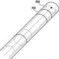
또한, 다른 일실시예는, 내시경(800)을 더 포함한다. 내시경(800)은, 도 9에서와 같이, 상기 튜브(600) 내를 관통한다. 예를 들어, 내시경(800)은 카테터 말단에 렌즈가 배치된 상태로 카테터 삽입 시에 튜브(600)와 함께 진행된다. 이를 통해, 의료진은, 카테터의 다양한 곡률의 휘어짐을 통해, 카테터가 진입하는 경로에 인접한 영역도 내시경(800)으로 확인할 수 있다.In addition, another embodiment includes the
또한, 다른 일실시예는, 도 7에서와 같이, 상기 제2탄성체(120)에 연결되며, 평평하거나 상기 카테터 진행방향에 수직한 방향으로 특정한 곡률로 휘어진(즉, 특정한 곡률반경(즉, 제3곡률반경)을 가지며 특정한 방향을 향해 만곡되게 돌출 형성된) 제3탄성체(130); 상기 제3탄성체(130)에 연결되며, 상기 제3탄성체(130)와 반대방향으로 휘어지거나 상이한 곡률로 휘어진(즉, 제3곡률반경과 상이한 곡률반경(즉, 제4곡률반경)을 가지면서 특정한 방향을 향해 만곡되게 돌출 형성되는) 제4탄성체(140); 상기 제3탄성체(130)의 일면에 연결되는 제3와이어(400); 및 상기 제3탄성체(130)의 상기 제3와이어(400)가 연결된 면의 반대면에 연결되는 제4와이어(500);를 더 포함한다. 즉, 제1탄성체(110)와 제2탄성체(120)가 연결된 제1밴팅섹션을 제1와이어(200)와 제2와이어(300)로 조절하고, 제3탄성체(130)와 제4탄성체(140)가 연결되어 형성되고 제1밴딩섹션에 연결되는 제2밴딩섹션을 제3와이어(400) 및 제4와이어(500)로 조절한다. 이를 통해, 카테터의 밴딩섹션(즉, 제1밴딩섹션과 제2밴딩섹션이 연결된 섹션)은 다양한 형태로 구부러질 수 있다. 예를 들어, 제1와이어(200) 또는 제2와이어(300)는 특정한 세기로 당겨지고, 제3와이어(400)와 제4와이어(500)는 제1와이어(200) 또는 제2와이어(300)가 당겨짐에 대해 제2밴딩섹션이 구부러지지 않도록 하는 힘으로 당겨짐에 따라, 카테터는 제1밴딩섹션 부분만 구부러지게 된다. 또한, 제1와이어(200)와 제2와이어(300)에는 힘이 가해지지 않고, 제3와이어(400) 또는 제4와이어(500)에만 힘이 가해짐에 따라, 카테터는 제2밴딩섹션만 구부러지게 된다.7, it is connected to the second
또한, 다른 일실시예는, 상기 제1와이어(200)와 상기 제2와이어(300)를 제어하여 제1방향 또는 제2방향으로의 휘어짐을 형성하는 조작부;를 더 포함한다. 즉, 조작부에 제1와이어(200)와 제2와이어(300)가 연결되어, 사용자(즉, 의료진)이 카테터에 구비된 조작부를 조작함에 따라 제1와이어(200)와 제2와이어(300)가 조절되어 제1방향 또는 제2방향으로 구부러지게 된다.In addition, another embodiment further includes an operation unit for controlling the
또한, 다른 일실시예는, 도 8에서와 같이, 상기 카테터의 외부로 노출되는 전극(700)을 포함한다. 카테터는 전극(700)을 통해 신체 내 특정지점의 전기신호를 측정하거나 전기적인 자극을 가한다. 카테터의 밴딩섹션에 의해 다양한 곡률로 카테터가 구부러짐에 따라, 의료진은 신체 내부의 원하는 위치에 카테터의 표면에 구비된 전극(700)이 용이하게 도달하도록 할 수 있다.Another embodiment also includes an
또한, 다른 일실시예는, 제1와이어(200) 또는 제2와이어(300)는 상기 전극(700)에 연결되는 전선으로 형성된다. 즉, 전선에 해당하는 제1와이어(200)와 제2와이어(300)가 밴딩섹션의 특정지점에 연결되고, 해당 특정지점과 카테터 표면에 배치된 전극(700)을 이어주는 전선에 연결된다. 이를 통해, 튜브(600) 내에 전극(700)에 연결되기 위해 통과되는 전선을 줄일 수 있다. 여러 개의 밴딩섹션(예를 들어, 제1밴딩섹션과 제2밴딩섹션)이 연결되면 와이어의 개수가 늘어가서 튜브(600) 내의 공간이 좁아질 수 있으므로, 와이어와 전선을 통합하여 튜브(600) 내의 전선 수를 줄여서 연결되는 단위밴딩섹션의 개수를 늘릴 수 있다.Also, in another embodiment, the
또한, 다른 일실시예는, 도 10에서와 같이, 상기 제1탄성체(110) 및 상기 제2탄성체(120)는, 상기 제1와이어(200)가 연결되는 면인 제1면(10) 및 상기 제2와이어(300)가 연결되는 면인 제2면(20)에 각각 상호 대응되는 개수의 풀리(151, 152)를 구비한다. 즉, 제1탄성체(110)의 제1면(10) 일측과 제2탄성체(120)의 제1면(10) 일측에 대응되는 개수의 풀리(151, 152)(예를 들어, 제1탄성체(110)와 제2탄성체(120)가 각각 1개의 풀리(151, 152))를 구비한다. 제1면(10)과 제2면(20)에 구비되는 풀리(151, 152)의 개수는 상이할 수 있다. 밴딩섹션의 양단에 풀리(151, 152)가 구비되도록, 제1탄성체(110)와 제2탄성체(120)는 결합부위의 반대되는 부분에 풀리(151, 152)를 구비할 수 있다.10, the first
상기 제1와이어(200)는 상기 제1탄성체(110)와 상기 제2탄성체(120)의 상기 제1면(10)에 구비된 풀리(151, 152)에 번갈아 감기고, 상기 제2와이어(300)는 상기 제1탄성체(110)와 상기 제2탄성체(120)의 상기 제2면(20)에 구비된 풀리(151, 152)에 번갈아 감긴다. 이를 통해, 제1와이어(200)와 제2와이어(300)는 움직도르레 원리가 적용되어 밴딩섹션에 힘을 가하게 되고, 외부에서 가한 힘에 비해 큰 힘이 밴딩섹션에 전달된다. 따라서, 밴딩섹션이 배치되지 않은 튜브(600) 영역의 강성을 약하게 하여도 밴딩섹션 조작을 위한 힘에 받는 영향을 줄일 수 있다.The
본 발명의 또 다른 일실시예에 따른 수술용 의료장치는, 카테터; 및 구동장치;를 포함한다. 상기 카테터는 본 발명의 실시예들에 따른 다곡률 카테터에 대해 상술된 바와 같다.A surgical medical device according to another embodiment of the present invention includes: a catheter; And a driving device. The catheter is as described above for a multi-curvature catheter according to embodiments of the present invention.
상기 구동장치는 상기 카테터 외부에 구비(즉, 신체 외부에 배치)되며, 상기 제1와이어(200)와 상기 제2와이어(300)를 당기는 정도를 제어하여 제1방향 또는 제2방향으로의 휘어짐을 제어하는 역할을 수행한다. 즉, 의료진이 원하는 휘어짐 상태를 입력하면, 구동장치는 계산결과를 기반으로 요청된 휘어짐 상태 구현을 위한 제1와이어(200) 및 제2와이어(300) 제어를 수행한다.The driving device is provided outside the catheter (i.e., disposed outside the body), and controls the degree of pulling of the
본 발명의 일실시예로, 상기 구동장치는, 사용자입력부; 제어부; 제1와이어구동부 및 제2와이어구동부;를 포함한다. 사용자입력부는 사용자의 카테터 제어요청을 수신한다. 상기 제어부는 카테터 제어요청에 상응하는 제1와이어(200) 및 제2와이어(300) 제어조건을 저장하고, 제1와이어구동부 및 제2와이어구동부에 제어요청을 수행한다.In one embodiment of the present invention, the driving apparatus includes a user input unit; A control unit; A first wire driver and a second wire driver. The user input receives a user ' s catheter control request. The control unit stores control conditions of the
상기 제1와이어구동부는 카테터의 제1와이어(200)가 연결되고, 상기 제2와이어구동부는 카테터의 제2와이어(300)가 연결된다. 제1와이어구동부 및 제2와이어구동부는 제어요청에 부합하게 제1와이어(200)와 제2와이어(300)에 힘을 가하는 역할을 수행한다. 제1와이어구동부 및 제2와이어구동부는 회전모터가 해당할 수 있고, 이외에 와이어 당김을 수행할 수 있는 다양한 수단이 적용될 수 있다.The first wire driving part is connected to the
또한, 다른 일실시예는, 상기 제2탄성체(120)에 연결되며, 평평하거나 상기 카테터 진행방향에 수직한 방향으로 특정한 곡률로 휘어진(즉, 특정한 곡률반경(즉, 제3곡률반경)을 가지며 특정한 방향을 향해 만곡되게 돌출 형성된) 제3탄성체(130); 상기 제3탄성체(130)에 연결되며, 상기 제3탄성체(130)와 반대방향으로 휘어지거나 상이한 곡률로 휘어진(즉, 제3곡률반경과 상이한 곡률반경(즉, 제4곡률반경)을 가지면서 특정한 방향을 향해 만곡되게 돌출 형성되는) 제4탄성체(140); 상기 제3탄성체(130)의 일면에 연결되는 제3와이어(400); 및 상기 제3탄성체(130)의 상기 제3와이어(400)가 연결된 면의 반대면에 연결되는 제4와이어(500);를 더 포함한다. 이 때, 상기 구동장치는, 상기 제1와이어(200), 상기 제2와이어(300), 상기 제3와이어(400) 및 상기 제4와이어(500)를 제어한다.In another embodiment, the second
상기와 같은 본 발명에 따르면, 아래와 같은 다양한 효과들을 가진다.According to the present invention as described above, the following various effects are obtained.
첫째, 카테터의 양방향으로 휘어지는 벤딩섹션 내의 지점을 상이하게 하여 곡률을 상이하게 형성함에 따라, 의료진은 신체부위 내의 특정지점에 접근하기 용이한 휘어짐 형태를 선택적으로 이용할 수 있다. 특히, 카테터가 진입한 경로(예를 들어, 심장혈관)와 가까운 영역에 카테터의 말단이 도달하기 위해, 벤딩섹션의 중간지점부터 휘어짐(즉, 제2탄성체는 휘어지지 않은 상태에서 제1탄성체만 휘어져서 짧은 구간이 휘어짐)에 따라 시술 부위 내에서 카테터 조작을 위한 와이어 제어가 간편해질 수 있다.First, by forming different curvatures by differentiating points in the bi-directionally bent bending section of the catheter, the medical practitioner can selectively use a warping form that is easy to approach a specific point in the body part. In particular, in order for the distal end of the catheter to reach the region close to the path (for example, a cardiovascular vessel) in which the catheter has entered, it is necessary to warp from the middle point of the bending section (i.e. the second elastic body The bending of the short section causes the wire control for catheter manipulation within the procedure site to be simplified.
구체적으로, 도 11(b)에서와 같이, 부정맥 시술에서 혈관(즉, 심장에 진입하는 특정한 경로)을 통해 들어간 카테터가 심장내벽의 A지점에 접근하기 위해 밴딩을 하는 경우, B지점에 접근 시와 동일한 휘어짐 조건을 이용하면 필요 이상의 카테터 전진 후 와이어를 B지점 접근 시에 비해 많이 당겨서 휘어짐을 크게 형성하여야 한다. 이 때, 본 발명의 실시예들과 같이 밴딩섹션에 포함된 제1탄성체만 휘어지고 제2탄성체는 휘어지지 않도록 하면, 하나의 곡률을 가진 카테터에 비해, 카테터 진입 경로에 가까운 지점에 카테터가 도달하여야 하는 경우, 카테터가 삽입되는 깊이(즉, 카테터가 전진되는 거리)가 짧아지며, 당겨져야 하는 와이어의 길이도 짧아질 수 있다. 즉, 본 발명의 실시예들은 기존 단일 곡률을 제공하는 카테터에 비해 시술 지점에 도달하기 위한 깊이 조절 동작 또는 곡률 조작 동작이 간편해질 수 있다.Specifically, as shown in FIG. 11 (b), when the catheter that enters the blood vessel (that is, the specific path to enter the heart) in the arrhythmia procedure performs banding to approach the point A on the inner wall of the heart, The wire should be pulled more than necessary when the catheter advances more than necessary to form a large warpage. At this time, as in the embodiments of the present invention, when only the first elastic body included in the bending section is bent and the second elastic body is not bent, compared to a catheter having one curvature, The depth at which the catheter is inserted (i.e., the distance that the catheter is advanced) is shortened, and the length of the wire to be pulled can be shortened. That is, the embodiments of the present invention can simplify the depth adjustment operation or the curvature manipulation operation to reach the treatment point compared to the catheter that provides the existing single curvature.
둘째, 탄성체 조합을 다양하게 함에 따라 다양한 구부러짐을 형성할 수 있다. 제1탄성체(110)와 제2탄성체(120)의 길이, 제1탄성체(110)와 제2탄성체(120)의 곡률 차이, 제1탄성체(110)와 제2탄성체(120)의 휘어진 방향 차이 등을 통해 카테터의 움직임을 다양하게 형성할 수 있다.Second, various flexures can be formed by varying the elastic combination. The lengths of the first and second
셋째, 기존의 다곡률을 구현하는 카테터는 방향에 따라 곡률을 다르게 형성하기 위해 탄성이 다른 재질을 추가하거나, 카테터 자체의 두께를 조절하는 하는 방법을 사용하므로 소형으로 제작하기 어려운 반면, 본 발명의 일실시예들에 따른 다곡률 카테터는 추가적인 구성없이 카테터 자체의 형상에 따라 다곡률을 구현할 수 있다. 특히, 카테터가 제공하여야 하는 모션 개수가 늘어나는 경우, 본 발명의 일실시예들은 단위벤딩섹션을 여러 개 연결함에 따라 다양한 카테터 모션을 구현할 수 있어, 구현 모션 개수에 의해 카테터가 커지는 문제가 발생하지 않는 효과가 있다.Thirdly, it is difficult to manufacture a conventional catheter having a multi-curvature because it uses a method of adding a material having different elasticity or adjusting the thickness of the catheter itself in order to form a curvature differently depending on a direction, The multi-curvature catheter according to one embodiment can achieve multi-curvature according to the shape of the catheter itself without additional configuration. In particular, when the number of motions that the catheter must provide increases, one embodiment of the present invention can implement various catheter motions by connecting multiple unit bending sections, It is effective.
이상, 첨부된 도면을 참조로 하여 본 발명의 실시예를 설명하였지만, 본 발명이 속하는 기술분야의 통상의 기술자는 본 발명이 그 기술적 사상이나 필수적인 특징을 변경하지 않고서 다른 구체적인 형태로 실시될 수 있다는 것을 이해할 수 있을 것이다. 그러므로, 이상에서 기술한 실시예들은 모든 면에서 예시적인 것이며, 제한적이 아닌 것으로 이해해야만 한다.While the present invention has been described in connection with what is presently considered to be practical exemplary embodiments, it is to be understood that the invention is not limited to the disclosed embodiments, but, on the contrary, You will understand. Therefore, it should be understood that the above-described embodiments are illustrative in all aspects and not restrictive.
100 : 벤딩섹션 110 : 제1탄성체
120 : 제2탄성체130 : 제3탄성체
140 : 제4탄성체151, 152 : 풀리
200 : 제1와이어300 : 제2와이어
400 : 제3와이어500 : 제4와이어
600 : 튜브700 : 전극
800 : 내시경100: bending section 110: first elastic body
120: second elastic member 130: third elastic member
140: fourth
200: first wire 300: second wire
400: third wire 500: fourth wire
600: tube 700: electrode
800: Endoscopy
Claims (15)
Translated fromKorean상기 카테터의 단부에 배치되고, 상호 대향하는 일면과 타면을 포함하는 제1탄성체;
상기 제1탄성체와 연결되고, 상호 대향하는 일면과 타면을 포함하는 제2탄성체;
상기 제1탄성체의 일면에 연결되는 제1와이어; 및
상기 제1탄성체의 타면에 연결되는 제2와이어를 포함하고,
상기 카테터는 상기 제1와이어에 의해 제1방향으로 굽힘이 형성되고, 상기 제2와이어에 의해 제2방향으로 굽힘이 형성되고,
상기 제2탄성체는 단면이 제2방향으로 볼록하도록 곡률이 형성되는 카테터.A catheter that forms a bend by a wire,
A first elastic body disposed at an end of the catheter, the first elastic body including a first surface and a second surface opposite to each other;
A second elastic body connected to the first elastic body, the second elastic body including one surface and the other surface facing each other;
A first wire connected to one surface of the first elastic body; And
And a second wire connected to the other surface of the first elastic body,
Wherein the catheter is bendable in a first direction by the first wire and is bent in a second direction by the second wire,
Wherein the second elastic body has a curvature such that the cross-section thereof is convex in the second direction.
상기 제1탄성체는 단면이 제1방향으로 볼록하도록 곡률이 형성되는 카테터.The method according to claim 1,
Wherein the first elastic body has a curvature formed such that its cross section is convex in the first direction.
상기 제1탄성체와, 상기 제2탄성체와, 상기 제1와이어와, 상기 제2와이어를 수용하는 튜브; 및
상기 튜브의 내측에 배치되고, 상기 제1탄성체 및 상기 제2탄성체와 이웃하여 배치되는 내시경을 더 포함하는 카테터.3. The method according to claim 1 or 2,
A tube accommodating the first elastic body, the second elastic body, the first wire, and the second wire; And
And an endoscope disposed inside the tube and disposed adjacent to the first elastic body and the second elastic body.
상기 제2탄성체와 연결되고, 상호 대향하는 일면과 타면을 포함하는 제3탄성체;
상기 제3탄성체와 연결되고, 상호 대향하는 일면과 타면을 포함하는 제4탄성체;
상기 제3탄성체의 일면에 연결되는 제3와이어; 및
상기 제3탄성체의 타면에 연결되는 제4와이어를 포함하고,
상기 제3탄성체는 평평하거나 단면이 제1방향으로 볼록하도록 곡률이 형성되고,
상기 제4탄성체는 평평하거나 단면이 제1방향 또는 제2방향으로 볼록하도록 곡률이 형성되는 카테터.3. The method according to claim 1 or 2,
A third elastic body connected to the second elastic body, the third elastic body including one surface and the other surface facing each other;
A fourth elastic body connected to the third elastic body, the fourth elastic body including one surface and the other surface facing each other;
A third wire connected to one surface of the third elastic body; And
And a fourth wire connected to the other surface of the third elastic body,
The third elastic body may be flat or have a curvature such that the cross section of the third elastic body is convex in the first direction,
Wherein the fourth elastic body is flat or curved so that its cross section is convex in the first direction or the second direction.
상기 제1와이어와 상기 제2와이어를 제어하여 제1방향 또는 제2방향으로의 굽힘을 형성하는 조작부를 더 포함하는 카테터.3. The method according to claim 1 or 2,
Further comprising an operating portion that controls the first wire and the second wire to form a bend in a first direction or a second direction.
상기 카테터의 외부로 노출되는 전극을 포함하고,
상기 제1와이어 및 상기 제2와이어 중 적어도 하나는 상기 전극에 연결되는 전선인 카테터.3. The method according to claim 1 or 2,
And an electrode exposed to the outside of the catheter,
Wherein at least one of the first wire and the second wire is a wire connected to the electrode.
상기 제1탄성체의 일면 및 타면과 상기 제2탄성체의 일면 및 타면에 각각 배치되는 복수 개의 풀리를 더 포함하고,
상기 제1와이어는 상기 제1탄성체의 일면과 상기 제2탄성체의 일면에 배치되는 상기 풀리에 감기고,
상기 제2와이어는 상기 제1탄성체의 타면과 상기 제2탄성체의 타면에 배치되는 상기 풀리에 감기는 카테터.3. The method according to claim 1 or 2,
Further comprising a plurality of pulleys disposed on one surface and the other surface of the first elastic body and on one surface and the other surface of the second elastic body, respectively,
Wherein the first wire is wound on one side of the first elastic body and on the other side of the second elastic body,
And the second wire is wound on the other surface of the first elastic body and on the other surface of the second elastic body.
상기 카테터는,
상기 카테터의 단부에 배치되고, 상호 대향하는 일면과 타면을 포함하는 제1탄성체;
상기 제1탄성체와 연결되고, 상호 대향하는 일면과 타면을 포함하는 제2탄성체;
상기 제1탄성체의 일면에 연결되는 제1와이어;
상기 제1탄성체의 타면에 연결되는 제2와이어; 및
상기 카테터의 외부로 노출되는 전극을 포함하고,
상기 구동장치는 상기 제1와이어와 상기 제2와이어를 제어하고,
상기 카테터는 상기 제1와이어에 의해 제1방향으로 굽힘이 형성되고, 상기 제2와이어에 의해 제2방향으로 굽힘이 형성되고,
상기 제2탄성체는 단면이 제2방향으로 볼록하도록 곡률이 형성되는 의료장치.A catheter and a drive device,
The catheter includes:
A first elastic body disposed at an end of the catheter, the first elastic body including a first surface and a second surface opposite to each other;
A second elastic body connected to the first elastic body, the second elastic body including one surface and the other surface facing each other;
A first wire connected to one surface of the first elastic body;
A second wire connected to the other surface of the first elastic body; And
And an electrode exposed to the outside of the catheter,
Wherein the driving device controls the first wire and the second wire,
Wherein the catheter is bendable in a first direction by the first wire and is bent in a second direction by the second wire,
And the curvature is formed so that the cross section of the second elastic body is convex in the second direction.
상기 제1탄성체는 단면이 제1방향으로 볼록하도록 곡률이 형성되는 의료장치.9. The method of claim 8,
Wherein the first elastic body has a curvature formed such that its cross section is convex in the first direction.
상기 카테터는,
상기 제2탄성체와 연결되고, 상호 대향하는 일면과 타면을 포함하는 제3탄성체;
상기 제3탄성체와 연결되고, 상호 대향하는 일면과 타면을 포함하는 제4탄성체;
상기 제3탄성체의 일면에 연결되는 제3와이어; 및
상기 제3탄성체의 타면에 연결되는 제4와이어를 더 포함하고,
상기 구동장치는 상기 제3와이어와 상기 제4와이어를 제어하고,
상기 제3탄성체는 평평하거나 단면이 제1방향으로 볼록하도록 곡률이 형성되고,
상기 제4탄성체는 평평하거나 단면이 제1방향 또는 제2방향으로 볼록하도록 곡률이 형성되는 의료장치.10. The method according to claim 8 or 9,
The catheter includes:
A third elastic body connected to the second elastic body, the third elastic body including one surface and the other surface facing each other;
A fourth elastic body connected to the third elastic body, the fourth elastic body including one surface and the other surface facing each other;
A third wire connected to one surface of the third elastic body; And
And a fourth wire connected to the other surface of the third elastic body,
The driving device controls the third wire and the fourth wire,
The third elastic body may be flat or have a curvature such that the cross section of the third elastic body is convex in the first direction,
Wherein the fourth elastic body is flat or has a curvature such that the cross section is convex in the first direction or the second direction.
상기 제1와이어 및 상기 제2와이어 중 적어도 하나는 상기 전극에 연결되는 전선인 의료장치.10. The method according to claim 8 or 9,
Wherein at least one of the first wire and the second wire is a wire connected to the electrode.
상기 제1탄성체의 말단과 상기 제2탄성체의 말단은 폭 전체가 결합되거나 또는 각각의 말단 형상을 유지한 상태로 접촉되는 부분만 결합되는 카테터.3. The method according to claim 1 or 2,
Wherein the distal end of the first elastic body and the distal end of the second elastic body are bonded to each other only at a portion where the entire width is engaged or the distal end of the second elastic body is held in contact with each other.
상기 제1탄성체와 상기 제2탄성체가 연결되어 형성되는 제1벤딩 섹션은 상기 제1와이어 및 상기 제2와이어에 의해 제어되고, 상기 제3탄성체와 상기 제4탄성체가 연결되어 형성되는 제2벤딩 섹션은 상기 제3와이어 및 상기 제4와이어에 의해 제어되는 카테터.5. The method of claim 4,
Wherein the first bending section formed by connecting the first elastic body and the second elastic body is controlled by the first wire and the second wire and the second bending section formed by connecting the third elastic body and the fourth elastic body, Section is controlled by the third wire and the fourth wire.
상기 제1탄성체는 상기 제2탄성체와 곡률 반경이 다른 카테터.3. The method of claim 2,
Wherein the first elastic body has a radius of curvature different from that of the second elastic body.
상기 제1탄성체와 상기 제2탄성체와 상기 제3탄성체와 상기 제4탄성체 중 적어도 하나는 다른 탄성체와 곡률 반경이 다른 카테터.5. The method of claim 4,
Wherein at least one of the first elastic body, the second elastic body, the third elastic body, and the fourth elastic body has a different radius of curvature from the other elastic body.
Priority Applications (4)
| Application Number | Priority Date | Filing Date | Title |
|---|---|---|---|
| KR1020170021831AKR101871221B1 (en) | 2017-02-17 | 2017-02-17 | Multi-culvature cathether and medical device for surgery |
| PCT/KR2018/001894WO2018151508A1 (en) | 2017-02-17 | 2018-02-13 | Catheter having multiple curvatures and medical apparatus for surgery |
| EP18754832.6AEP3583974B1 (en) | 2017-02-17 | 2018-02-13 | Catheter having multiple curvatures and medical apparatus for surgery |
| US16/530,005US11253678B2 (en) | 2017-02-17 | 2019-08-02 | Multi-curvature catheter and medical device for surgery |
Applications Claiming Priority (1)
| Application Number | Priority Date | Filing Date | Title |
|---|---|---|---|
| KR1020170021831AKR101871221B1 (en) | 2017-02-17 | 2017-02-17 | Multi-culvature cathether and medical device for surgery |
Publications (1)
| Publication Number | Publication Date |
|---|---|
| KR101871221B1true KR101871221B1 (en) | 2018-06-27 |
Family
ID=62789722
Family Applications (1)
| Application Number | Title | Priority Date | Filing Date |
|---|---|---|---|
| KR1020170021831AActiveKR101871221B1 (en) | 2017-02-17 | 2017-02-17 | Multi-culvature cathether and medical device for surgery |
Country Status (4)
| Country | Link |
|---|---|
| US (1) | US11253678B2 (en) |
| EP (1) | EP3583974B1 (en) |
| KR (1) | KR101871221B1 (en) |
| WO (1) | WO2018151508A1 (en) |
Cited By (2)
| Publication number | Priority date | Publication date | Assignee | Title |
|---|---|---|---|---|
| CN112205951A (en)* | 2020-10-12 | 2021-01-12 | 武汉佑康科技有限公司 | Directional bent endoscope catheter |
| KR102296024B1 (en)* | 2021-04-01 | 2021-09-01 | 주식회사 딥큐어 | Electrode apparatus for blocking or controlling nerve inside body |
Families Citing this family (2)
| Publication number | Priority date | Publication date | Assignee | Title |
|---|---|---|---|---|
| CA3149483A1 (en) | 2019-08-02 | 2021-02-11 | Vizaramed, Inc. | Steerable sheath |
| CN114376769A (en)* | 2022-01-24 | 2022-04-22 | 上海臻亿医疗科技有限公司 | delivery catheter |
Citations (3)
| Publication number | Priority date | Publication date | Assignee | Title |
|---|---|---|---|---|
| JPH07213618A (en)* | 1994-01-31 | 1995-08-15 | Nippon Zeon Co Ltd | Medical equipment |
| JPH0819618A (en)* | 1994-07-07 | 1996-01-23 | Olympus Optical Co Ltd | Flexible tube |
| US20020068868A1 (en)* | 1990-02-02 | 2002-06-06 | Thompson Russell B. | Assemblies for creating compound curves in distal catheter regions |
Family Cites Families (7)
| Publication number | Priority date | Publication date | Assignee | Title |
|---|---|---|---|---|
| US5254088A (en)* | 1990-02-02 | 1993-10-19 | Ep Technologies, Inc. | Catheter steering mechanism |
| US5314466A (en)* | 1992-04-13 | 1994-05-24 | Ep Technologies, Inc. | Articulated unidirectional microwave antenna systems for cardiac ablation |
| US5782828A (en)* | 1996-12-11 | 1998-07-21 | Irvine Biomedical, Inc. | Ablation catheter with multiple flexible curves |
| US6579279B1 (en)* | 1999-09-24 | 2003-06-17 | Omnisonics Medical Technologies, Inc. | Steerable catheter device |
| US7959601B2 (en)* | 2005-02-14 | 2011-06-14 | Biosense Webster, Inc. | Steerable catheter with in-plane deflection |
| FR2921499B1 (en)* | 2007-09-26 | 2009-11-13 | Snecma | CATHETER OR ENDOSCOPE-TYPE ORIENTABLE STRUCTURE |
| EP2407199A4 (en) | 2009-03-09 | 2014-08-13 | Sumitomo Bakelite Co | Catheter and method of manufacturing catheter |
- 2017
- 2017-02-17KRKR1020170021831Apatent/KR101871221B1/enactiveActive
- 2018
- 2018-02-13WOPCT/KR2018/001894patent/WO2018151508A1/ennot_activeCeased
- 2018-02-13EPEP18754832.6Apatent/EP3583974B1/enactiveActive
- 2019
- 2019-08-02USUS16/530,005patent/US11253678B2/enactiveActive
Patent Citations (3)
| Publication number | Priority date | Publication date | Assignee | Title |
|---|---|---|---|---|
| US20020068868A1 (en)* | 1990-02-02 | 2002-06-06 | Thompson Russell B. | Assemblies for creating compound curves in distal catheter regions |
| JPH07213618A (en)* | 1994-01-31 | 1995-08-15 | Nippon Zeon Co Ltd | Medical equipment |
| JPH0819618A (en)* | 1994-07-07 | 1996-01-23 | Olympus Optical Co Ltd | Flexible tube |
Cited By (3)
| Publication number | Priority date | Publication date | Assignee | Title |
|---|---|---|---|---|
| CN112205951A (en)* | 2020-10-12 | 2021-01-12 | 武汉佑康科技有限公司 | Directional bent endoscope catheter |
| KR102296024B1 (en)* | 2021-04-01 | 2021-09-01 | 주식회사 딥큐어 | Electrode apparatus for blocking or controlling nerve inside body |
| WO2022211157A1 (en)* | 2021-04-01 | 2022-10-06 | 주식회사 딥큐어 | Electrode device for blocking or controlling nerves in body |
Also Published As
| Publication number | Publication date |
|---|---|
| US20190351190A1 (en) | 2019-11-21 |
| EP3583974B1 (en) | 2021-03-24 |
| US11253678B2 (en) | 2022-02-22 |
| WO2018151508A1 (en) | 2018-08-23 |
| EP3583974A1 (en) | 2019-12-25 |
| EP3583974A4 (en) | 2020-02-26 |
Similar Documents
| Publication | Publication Date | Title |
|---|---|---|
| US20220111176A1 (en) | Introducer with steerable distal tip section | |
| KR101871221B1 (en) | Multi-culvature cathether and medical device for surgery | |
| JP6655655B2 (en) | Asymmetric catheter curved shape | |
| US10874832B2 (en) | Deflectable catheter shaft | |
| JP6524123B2 (en) | Manipulatable medical delivery device and method of use | |
| US6544215B1 (en) | Steerable device for introducing diagnostic and therapeutic apparatus into the body | |
| JP5405742B2 (en) | Operable catheter | |
| JP2012050855A (en) | Asymmetrical bidirectional steerable catheter | |
| WO1994009843A1 (en) | Catheter having a multiple durometer | |
| EP1231973A4 (en) | ORIENTABLE CATHETER | |
| JP7654796B2 (en) | Steerable catheter with spine reinforced molded articulation joint | |
| JP2023154104A (en) | Articulating microsurgical instrument | |
| US10582976B2 (en) | Manipulator system and manipulator control method | |
| KR102348858B1 (en) | Flexible multi-joint apparatus | |
| JPH11267095A (en) | Tubular insert tool | |
| US20230121016A1 (en) | Elongated medical device | |
| CA3117752A1 (en) | Steerable elongated functional system | |
| KR102557473B1 (en) | Guiding cathether for installing at medical robot | |
| JPH11155806A (en) | Endoscope | |
| WO2019207676A1 (en) | Treatment instrument and treatment system | |
| JP2968266B1 (en) | Medical catheter | |
| KR20230087002A (en) | Cathter, method for controlling catheter and catether system | |
| JPH0780079A (en) | Catheter tube with swing mechanism | |
| JP2017221716A (en) | Actuator deterrence assembly for medical devices |
Legal Events
| Date | Code | Title | Description |
|---|---|---|---|
| PA0109 | Patent application | Patent event code:PA01091R01D Comment text:Patent Application Patent event date:20170217 | |
| PA0201 | Request for examination | ||
| PE0902 | Notice of grounds for rejection | Comment text:Notification of reason for refusal Patent event date:20180207 Patent event code:PE09021S01D | |
| E90F | Notification of reason for final refusal | ||
| PE0902 | Notice of grounds for rejection | Comment text:Final Notice of Reason for Refusal Patent event date:20180509 Patent event code:PE09021S02D | |
| E701 | Decision to grant or registration of patent right | ||
| PE0701 | Decision of registration | Patent event code:PE07011S01D Comment text:Decision to Grant Registration Patent event date:20180618 | |
| GRNT | Written decision to grant | ||
| PR0701 | Registration of establishment | Comment text:Registration of Establishment Patent event date:20180620 Patent event code:PR07011E01D | |
| PR1002 | Payment of registration fee | Payment date:20180620 End annual number:3 Start annual number:1 | |
| PG1601 | Publication of registration | ||
| PR1001 | Payment of annual fee | Payment date:20210601 Start annual number:4 End annual number:4 | |
| PR1001 | Payment of annual fee | Payment date:20220329 Start annual number:5 End annual number:5 | |
| PR1001 | Payment of annual fee | Payment date:20240409 Start annual number:7 End annual number:7 |