KR101868273B1 - Control device for suppling of working fluid - Google Patents
Control device for suppling of working fluidDownload PDFInfo
- Publication number
- KR101868273B1 KR101868273B1KR1020170039383AKR20170039383AKR101868273B1KR 101868273 B1KR101868273 B1KR 101868273B1KR 1020170039383 AKR1020170039383 AKR 1020170039383AKR 20170039383 AKR20170039383 AKR 20170039383AKR 101868273 B1KR101868273 B1KR 101868273B1
- Authority
- KR
- South Korea
- Prior art keywords
- working fluid
- tank
- compressor
- fluid
- inlet
- Prior art date
- Legal status (The legal status is an assumption and is not a legal conclusion. Google has not performed a legal analysis and makes no representation as to the accuracy of the status listed.)
- Active
Links
- 239000012530fluidSubstances0.000titleclaimsabstractdescription213
- 238000003860storageMethods0.000claimsabstractdescription53
- 238000001816coolingMethods0.000claimsabstractdescription5
- 238000010248power generationMethods0.000claimsdescription29
- 238000000034methodMethods0.000claimsdescription24
- 238000007599dischargingMethods0.000claimsdescription9
- 238000005243fluidizationMethods0.000claimsdescription3
- CURLTUGMZLYLDI-UHFFFAOYSA-NCarbon dioxideChemical compoundO=C=OCURLTUGMZLYLDI-UHFFFAOYSA-N0.000description52
- 229910002092carbon dioxideInorganic materials0.000description26
- 239000001569carbon dioxideSubstances0.000description26
- 239000007789gasSubstances0.000description14
- 239000002918waste heatSubstances0.000description11
- 230000008859changeEffects0.000description8
- 238000010586diagramMethods0.000description6
- 238000010276constructionMethods0.000description3
- 239000003344environmental pollutantSubstances0.000description3
- 239000000463materialSubstances0.000description3
- 231100000719pollutantToxicity0.000description3
- 230000003139buffering effectEffects0.000description2
- 230000007423decreaseEffects0.000description2
- 238000012546transferMethods0.000description2
- 230000008901benefitEffects0.000description1
- 230000006835compressionEffects0.000description1
- 238000007906compressionMethods0.000description1
- 239000012809cooling fluidSubstances0.000description1
- 239000000498cooling waterSubstances0.000description1
- 230000005611electricityEffects0.000description1
- 238000005188flotationMethods0.000description1
- 239000012535impuritySubstances0.000description1
- 238000002347injectionMethods0.000description1
- 239000007924injectionSubstances0.000description1
- 239000007788liquidSubstances0.000description1
- 238000005461lubricationMethods0.000description1
- 238000004519manufacturing processMethods0.000description1
- 238000012986modificationMethods0.000description1
- 230000004048modificationEffects0.000description1
- 230000008569processEffects0.000description1
- 230000035484reaction timeEffects0.000description1
- 230000009467reductionEffects0.000description1
- 239000003507refrigerantSubstances0.000description1
- 238000012827research and developmentMethods0.000description1
- 230000004044responseEffects0.000description1
- 238000007789sealingMethods0.000description1
- 239000000126substanceSubstances0.000description1
- 239000013589supplementSubstances0.000description1
- XLYOFNOQVPJJNP-UHFFFAOYSA-NwaterSubstancesOXLYOFNOQVPJJNP-UHFFFAOYSA-N0.000description1
Images


Classifications
- F—MECHANICAL ENGINEERING; LIGHTING; HEATING; WEAPONS; BLASTING
- F01—MACHINES OR ENGINES IN GENERAL; ENGINE PLANTS IN GENERAL; STEAM ENGINES
- F01K—STEAM ENGINE PLANTS; STEAM ACCUMULATORS; ENGINE PLANTS NOT OTHERWISE PROVIDED FOR; ENGINES USING SPECIAL WORKING FLUIDS OR CYCLES
- F01K25/00—Plants or engines characterised by use of special working fluids, not otherwise provided for; Plants operating in closed cycles and not otherwise provided for
- F01K25/08—Plants or engines characterised by use of special working fluids, not otherwise provided for; Plants operating in closed cycles and not otherwise provided for using special vapours
- F01K25/10—Plants or engines characterised by use of special working fluids, not otherwise provided for; Plants operating in closed cycles and not otherwise provided for using special vapours the vapours being cold, e.g. ammonia, carbon dioxide, ether
- F01K25/103—Carbon dioxide
- F—MECHANICAL ENGINEERING; LIGHTING; HEATING; WEAPONS; BLASTING
- F01—MACHINES OR ENGINES IN GENERAL; ENGINE PLANTS IN GENERAL; STEAM ENGINES
- F01K—STEAM ENGINE PLANTS; STEAM ACCUMULATORS; ENGINE PLANTS NOT OTHERWISE PROVIDED FOR; ENGINES USING SPECIAL WORKING FLUIDS OR CYCLES
- F01K13/00—General layout or general methods of operation of complete plants
- F01K13/006—Auxiliaries or details not otherwise provided for
- F—MECHANICAL ENGINEERING; LIGHTING; HEATING; WEAPONS; BLASTING
- F01—MACHINES OR ENGINES IN GENERAL; ENGINE PLANTS IN GENERAL; STEAM ENGINES
- F01K—STEAM ENGINE PLANTS; STEAM ACCUMULATORS; ENGINE PLANTS NOT OTHERWISE PROVIDED FOR; ENGINES USING SPECIAL WORKING FLUIDS OR CYCLES
- F01K19/00—Regenerating or otherwise treating steam exhausted from steam engine plant
- F01K19/02—Regenerating by compression
- F01K19/04—Regenerating by compression in combination with cooling or heating
- F—MECHANICAL ENGINEERING; LIGHTING; HEATING; WEAPONS; BLASTING
- F01—MACHINES OR ENGINES IN GENERAL; ENGINE PLANTS IN GENERAL; STEAM ENGINES
- F01K—STEAM ENGINE PLANTS; STEAM ACCUMULATORS; ENGINE PLANTS NOT OTHERWISE PROVIDED FOR; ENGINES USING SPECIAL WORKING FLUIDS OR CYCLES
- F01K3/00—Plants characterised by the use of steam or heat accumulators, or intermediate steam heaters, therein
- F01K3/14—Plants characterised by the use of steam or heat accumulators, or intermediate steam heaters, therein having both steam accumulator and heater, e.g. superheating accumulator
- F01K3/16—Mutual arrangement of accumulator and heater
- F—MECHANICAL ENGINEERING; LIGHTING; HEATING; WEAPONS; BLASTING
- F01—MACHINES OR ENGINES IN GENERAL; ENGINE PLANTS IN GENERAL; STEAM ENGINES
- F01K—STEAM ENGINE PLANTS; STEAM ACCUMULATORS; ENGINE PLANTS NOT OTHERWISE PROVIDED FOR; ENGINES USING SPECIAL WORKING FLUIDS OR CYCLES
- F01K7/00—Steam engine plants characterised by the use of specific types of engine; Plants or engines characterised by their use of special steam systems, cycles or processes; Control means specially adapted for such systems, cycles or processes; Use of withdrawn or exhaust steam for feed-water heating
- F01K7/16—Steam engine plants characterised by the use of specific types of engine; Plants or engines characterised by their use of special steam systems, cycles or processes; Control means specially adapted for such systems, cycles or processes; Use of withdrawn or exhaust steam for feed-water heating the engines being only of turbine type
- F01K7/165—Controlling means specially adapted therefor
- F—MECHANICAL ENGINEERING; LIGHTING; HEATING; WEAPONS; BLASTING
- F01—MACHINES OR ENGINES IN GENERAL; ENGINE PLANTS IN GENERAL; STEAM ENGINES
- F01K—STEAM ENGINE PLANTS; STEAM ACCUMULATORS; ENGINE PLANTS NOT OTHERWISE PROVIDED FOR; ENGINES USING SPECIAL WORKING FLUIDS OR CYCLES
- F01K7/00—Steam engine plants characterised by the use of specific types of engine; Plants or engines characterised by their use of special steam systems, cycles or processes; Control means specially adapted for such systems, cycles or processes; Use of withdrawn or exhaust steam for feed-water heating
- F01K7/32—Steam engine plants characterised by the use of specific types of engine; Plants or engines characterised by their use of special steam systems, cycles or processes; Control means specially adapted for such systems, cycles or processes; Use of withdrawn or exhaust steam for feed-water heating the engines using steam of critical or overcritical pressure
- F—MECHANICAL ENGINEERING; LIGHTING; HEATING; WEAPONS; BLASTING
- F22—STEAM GENERATION
- F22D—PREHEATING, OR ACCUMULATING PREHEATED, FEED-WATER FOR STEAM GENERATION; FEED-WATER SUPPLY FOR STEAM GENERATION; CONTROLLING WATER LEVEL FOR STEAM GENERATION; AUXILIARY DEVICES FOR PROMOTING WATER CIRCULATION WITHIN STEAM BOILERS
- F22D3/00—Accumulators for preheated water
- F—MECHANICAL ENGINEERING; LIGHTING; HEATING; WEAPONS; BLASTING
- F22—STEAM GENERATION
- F22D—PREHEATING, OR ACCUMULATING PREHEATED, FEED-WATER FOR STEAM GENERATION; FEED-WATER SUPPLY FOR STEAM GENERATION; CONTROLLING WATER LEVEL FOR STEAM GENERATION; AUXILIARY DEVICES FOR PROMOTING WATER CIRCULATION WITHIN STEAM BOILERS
- F22D5/00—Controlling water feed or water level; Automatic water feeding or water-level regulators
- F22D5/06—Controlling water feed or water level; Automatic water feeding or water-level regulators with receptacles external to, but in free communication with, the boilers and adapted to move up and down in accordance with change in water level
Landscapes
- Engineering & Computer Science (AREA)
- Mechanical Engineering (AREA)
- General Engineering & Computer Science (AREA)
- Chemical & Material Sciences (AREA)
- Combustion & Propulsion (AREA)
- Physics & Mathematics (AREA)
- Thermal Sciences (AREA)
- Chemical Kinetics & Catalysis (AREA)
- Engine Equipment That Uses Special Cycles (AREA)
- Structures Of Non-Positive Displacement Pumps (AREA)
Abstract
Description
Translated fromKorean본 발명은 작동 유체 공급 제어 장치에 관한 것으로, 더욱 상세하게는 작동 유체의 유량 및 압력을 효율적이고 경제적으로 제어해 발전 사이클 내로 공급할 수 있는 작동 유체 공급 제어 장치에 관한 것이다.BACKGROUND OF THE INVENTION 1. Field of the Invention The present invention relates to a working fluid supply control device, and more particularly, to a working fluid supply control device that can efficiently and economically control the flow rate and pressure of a working fluid to supply the fluid into a power generation cycle.
국제적으로 효율적인 전력 생산에 대한 필요성이 점차 커지고 있고, 공해물질 발생을 줄이기 위한 움직임이 점차 활발해짐에 따라 공해물질의 발생을 줄이면서 전력 생산량을 높이기 위해 여러 가지 노력을 기울이고 있다. 그러한 노력의 하나로 초임계 이산화탄소를 작동 유체로 사용하는 초임계 이산화탄소 발전 시스템(Power generation system using Supercritical CO2)에 대한 연구 개발이 활성화되고 있다.Internationally, there is an increasing need for efficient power generation. As the movement to reduce the generation of pollutants becomes more active, various efforts are being made to increase the production of electricity while reducing the generation of pollutants. As one of such efforts, research and development on a supercritical carbon dioxide (CO2) power generation system using supercritical carbon dioxide as a working fluid has been activated.
초임계 상태의 이산화탄소는 액체 상태와 유사한 밀도에 기체와 비슷한 점성을 동시에 가지므로 기기의 소형화와 더불어, 유체의 압축 및 순환에 필요한 전력소모를 최소화할 수 있다. 동시에 임계점이 섭씨 31.4도, 72.8기압으로, 임계점이 섭씨 373.95도, 217.7기압인 물보다 매우 낮아서 다루기가 용이한 장점이 있다.Since supercritical carbon dioxide has a gas-like viscosity at a density similar to that of a liquid state, it can minimize the power consumption required for compression and circulation of the fluid as well as miniaturization of the apparatus. At the same time, the critical point is 31.4 degrees Celsius, 72.8 atmospheres, and the critical point is much lower than the water at 373.95 degrees Celsius and 217.7 atmospheres, which is easy to handle.
또한, 초임계 이산화탄소 발전 시스템은 발전에 사용된 이산화탄소를 외부로 배출하지 않는 폐사이클(closed cycle)로 운영되는 경우가 대부분이기 때문에 국가별 공해물질 배출 감소에 큰 도움이 될 수 있다.In addition, the supercritical carbon dioxide power generation system is often operated as a closed cycle in which the carbon dioxide used in the power generation is not discharged to the outside, which can greatly contribute to reduction of pollutant emissions by country.
일반적으로 초임계 이산화탄소 발전 시스템은 발전에 사용된 이산화탄소를 외부로 배출하지 않는 폐사이클(close cycle)을 이루며, 작동 유체로 초임계 상태의 이산화탄소를 이용한다.Generally, a supercritical carbon dioxide power generation system forms a closed cycle that does not discharge the carbon dioxide used for power generation, and uses supercritical carbon dioxide as a working fluid.
작동유체는 발전 사이클 내로 주입되어 터보기기를 구동시키는 발전용과, 터보기기의 베어링 윤활 및 실링을 위한 터보기기용의 두가지 목적으로 사이클 내로 공급된다. 작동 유체의 공급 방법의 일 예가 미국특허등록 8281593호에 개시되어 있다.The working fluid is fed into the cycle for two purposes: power generation, which is injected into the power generation cycle to drive the turbo machinery, and turbo machines for bearing lubrication and sealing of the turbo machine. One example of a method of supplying a working fluid is disclosed in U.S. Patent No. 8281593. [
전술한 선행문헌에 개시된 작동 유체의 충전 시스템은 저장 탱크에 저장된 작동 유체를 고압용 피스톤 펌프를 이용해 사이클 내부 및 터보 머신으로 공급하는 방식이다. 또한, 작동 유체의 유량 제어 및 압축기 입출구의 압력 제어를 위해 매스 컨트롤 탱크(mass control tank)가 구비된다. 매스 컨트롤 탱크는 인벤토리 탱크(Inventory tank)라고도 하며, 일반적으로 매스 컨트롤 탱크는 압축기 출구 고압 라인과 프리 쿨러의 입구 저압 라인에 연결되도록 설치된다. 압축기 출구 압력이 증가할 때 고압 밸브를 열어 유량의 일부를 매스 컨트롤 탱크로 보내 압력을 감소할 수 있다. 압축기 입구 압력이 감소할 때 저압 밸브를 열어 매스 컨트롤 탱크의 일부 유량을 압축기 입구 라인으로 보내 압력을 증가시킬 수 있다.The working fluid filling system disclosed in the above-mentioned prior art is a method of supplying the working fluid stored in the storage tank to the inside of the cycle and the turbo machine using the high-pressure piston pump. Further, a mass control tank is provided for controlling the flow rate of the working fluid and controlling the pressure at the inlet and outlet of the compressor. The mass control tank is also referred to as an inventory tank, and in general, the mass control tank is connected to the compressor outlet high pressure line and to the inlet low pressure line of the precooler. As the compressor outlet pressure increases, the high pressure valve can be opened to send some of the flow rate to the mass control tank to reduce the pressure. As the compressor inlet pressure decreases, the low pressure valve can be opened to send some flow of the mass control tank to the compressor inlet line to increase the pressure.
따라서 매스 컨트롤 탱크는 압축기 출구 고압 라인에 연결되므로 고압에 견딜 수 있는 고가의 재질 및 부품으로 구성되는 것이 필수적이므로, 비용이 비싸고 경제성이 떨어지는 문제가 있다.Therefore, since the mass control tank is connected to the high-pressure line of the compressor outlet, it is essential that the mass control tank is made of expensive materials and parts capable of withstanding high pressure, which is costly and inexpensive.
본 발명의 목적은 작동 유체의 유량 및 압력을 효율적이고 경제적으로 제어해 발전 사이클 내로 공급할 수 있는 작동 유체 공급 제어 장치를 제공하는 것이다.An object of the present invention is to provide a working fluid supply control device which can efficiently and economically control the flow rate and pressure of a working fluid and supply it into a power generation cycle.
본 발명의 작동 유체 공급 제어 장치는, 작동 유체를 압축하는 압축기와, 상기 압축기로 공급되는 작동 유체를 냉각하는 프리 쿨러가 구비된 발전 사이클로 작동 유체를 공급하기 위한 작동 유체 공급 제어 장치에 있어서, 상기 발전 사이클로 공급되는 상기 작동 유체를 저장하는 저장 탱크와, 상기 프리 쿨러와 상기 압축기의 사이에 배치되어 상기 작동 유체가 유동하거나 일시 저장되는 플로테이션 탱크를 포함하며, 상기 압축기 입구 및 상기 프리 쿨러의 출구의 압력에 따라 상기 플로테이션 탱크 내 압력 및 상기 작동 유체의 유량이 제어되는 것을 특징으로 한다.A working fluid supply control device for supplying a working fluid to a power generation cycle provided with a compressor for compressing a working fluid and a precooler for cooling a working fluid supplied to the compressor, A reservoir tank for storing the working fluid to be supplied to the power generation cycle; and a floatation tank disposed between the pre-cooler and the compressor for flowing or temporarily storing the working fluid, wherein the outlet of the compressor and the outlet of the pre- The pressure in the floatation tank and the flow rate of the working fluid are controlled according to the pressure of the working fluid.
상기 저장 탱크와 상기 플로테이션 탱크의 사이에 구비되어 상기 저장 탱크로부터 상기 작동 유체를 상기 플로테이션 탱크로 공급하는 공급 펌프와, 상기 저장 탱크와 상기 플로테이션 탱크의 사이에 구비되어 상기 플로테이션 탱크로부터 상기 작동 유체를 상기 저장 탱크로 배출하기 위한 제어 밸브를 더 포함한다.A supply pump provided between the storage tank and the floatation tank for supplying the working fluid from the storage tank to the floatation tank and a supply pump provided between the storage tank and the floatation tank, And a control valve for discharging the working fluid to the storage tank.
상기 플로테이션 탱크는 피스톤 축압기(accumulator) 타입의 탱크인 것을 특징으로 한다.The storage tank may be a tank accumulator type tank.
상기 플로테이션 탱크는 상기 작동 유체가 유입되는 탱크 본체와, 상기 탱크 본체의 내부에 설치 외부에서 공급되는 제어용 유체에 의해 승강하는 피스톤을 포함한다.The tank includes a tank body into which the working fluid flows and a piston which moves up and down by a control fluid supplied from the outside in the tank body.
상기 플로테이션 탱크는 상기 탱크 본체의 하단에 구비되어 상기 제어용 유체가 유출입하는 제어 유체 유입부와, 상기 탱크 본체의 일측에 구비되어 상기 공급 펌프로부터 상기 작동 유체가 유입되는 제1 입구와, 상기 탱크 본체의 타측에 구비되어 상기 제어 밸브로 상기 작동 유체가 배출되는 제1 출구를 더 포함한다.The control fluid flowing in and flowing out of the control fluid is provided at a lower end of the tank main body, a first inlet provided at one side of the tank main body and through which the working fluid flows from the supply pump, And a first outlet provided on the other side of the main body for discharging the working fluid to the control valve.
상기 플로테이션 탱크는 상기 탱크 본체의 상부에 구비되어 상기 프리 쿨러로부터 상기 작동 유체가 유입되는 제2 입구와, 상기 탱크 본체의 상부에 구비되어 상기 압축기로 상기 작동 유체가 배출되는 제2 출구를 더 포함한다.And a second outlet provided at an upper portion of the tank main body and through which the working fluid is discharged by the compressor, the second inlet being provided at an upper portion of the tank main body and through which the working fluid flows from the precooler, .
상기 프리 쿨러 후단에서의 압력인 P1 또는 상기 압축기 전단에서의 압력인이 P2가 높아지는 경우, 상기 제어 유체 유입부로 상기 제어용 유체가 공급되고, 상기 제어 밸브를 개방해 상기 제1 출구를 통해 상기 플로테이션 탱크 내의 작동 유체를 상기 저장 탱크로 배출하는 것을 특징으로 한다.Wherein the control fluid is supplied to the control fluid inlet when the pressure P1 at the rear end of the pre-cooler or the pressure P2 at the front end of the compressor becomes high and the control fluid is supplied to the control fluid inlet, And the working fluid in the tank is discharged to the storage tank.
상기 제어용 유체의 공급 및 상기 저장 탱크로의 상기 작동 유체의 배출은 상기 피스톤의 높이가 설정값에 대응하는 높이에 도달할 때까지 이루어지는 것을 특징으로 한다.Wherein supply of the control fluid and discharge of the working fluid to the storage tank are performed until the height of the piston reaches a height corresponding to the set value.
상기 프리 쿨러 후단에서의 압력인 P1 또는 상기 압축기 전단에서의 압력인이 P2가 낮아지는 경우, 상기 공급 펌프를 작동해 상기 제1 입구를 통해 상기 플로테이션 탱크 내로 상기 작동 유체를 공급하는 것을 특징으로 한다.When the pressure P1 at the rear end of the pre-cooler or the pressure P2 at the front end of the compressor is low, the supply pump is operated to supply the working fluid into the floatation tank through the first inlet do.
상기 플로테이션 탱크 내로의 상기 작동 유체의 공급은 상기 피스톤의 높이가 설정값에 대응하는 높이에 도달할 때까지 이루어지는 것을 특징으로 한다.And the supplying of the working fluid into the floatation tank is performed until the height of the piston reaches a height corresponding to the set value.
또한, 본 발명은 작동 유체를 압축하는 압축기와, 상기 압축기로 공급되는 작동 유체를 냉각하는 프리 쿨러가 구비된 발전 사이클로 작동 유체를 공급하기 위한 작동 유체 공급 제어 장치에 있어서, 상기 발전 사이클로 공급되는 상기 작동 유체를 저장하는 저장 탱크와, 상기 압축기의 입구 저압 라인에 배치되어 상기 작동 유체가 유동하거나 일시 저장되는 플로테이션 탱크와, 상기 저장 탱크와 상기 플로테이션 탱크의 사이에 구비되어 상기 저장 탱크로부터 상기 작동 유체를 상기 플로테이션 탱크로 공급하는 공급 펌프와, 상기 저장 탱크와 상기 플로테이션 탱크의 사이에 구비되어 상기 플로테이션 탱크로부터 상기 작동 유체를 상기 저장 탱크로 배출하기 위한 제어 밸브를 포함하는 작동 유체 공급 제어 장치를 제공할 수 있다.The present invention also provides a working fluid supply control device for supplying a working fluid to a power generation cycle including a compressor for compressing a working fluid and a precooler for cooling a working fluid supplied to the compressor, A storage tank for storing a working fluid; a floatation tank disposed in an inlet low-pressure line of the compressor for flowing or temporarily storing the working fluid; and a storage tank disposed between the storage tank and the storage tank, A supply pump for supplying a working fluid to the storage tank and a control valve provided between the storage tank and the storage tank for discharging the working fluid from the storage tank to the storage tank, A supply control device can be provided.
상기 프리 쿨러의 출구 또는 상기 압축기 입구의 압력이 높아지면 상기 플로테이션 탱크로부터 상기 작동 유체를 상기 저장 탱크로 배출시키고, 상기 프리 쿨러의 출구 또는 상기 압축기 입구의 압력이 낮아지면 상기 저장 탱크로부터 상기 플로테이션 탱크로 상기 작동 유체를 공급하는 것을 특징으로 한다.The control unit discharges the working fluid from the storage tank to the storage tank when the outlet of the pre-cooler or the pressure of the compressor inlet becomes high. When the pressure of the outlet of the pre-cooler or the inlet of the compressor becomes low, And the working fluid is supplied to the tank.
상기 플로테이션 탱크는 피스톤 축압기(accumulator) 타입의 탱크인 것을 특징으로 한다.The storage tank may be a tank accumulator type tank.
상기 플로테이션 탱크는 상기 작동 유체가 유입되는 탱크 본체와, 상기 탱크 본체의 내부에 설치 외부에서 공급되는 제어용 유체에 의해 승강하는 피스톤을 포함한다.The tank includes a tank body into which the working fluid flows and a piston which moves up and down by a control fluid supplied from the outside in the tank body.
상기 플로테이션 탱크는 상기 탱크 본체의 하단에 구비되어 상기 제어용 유체가 유출입하는 제어 유체 유입부와, 상기 탱크 본체의 일측에 구비되어 상기 공급 펌프로부터 상기 작동 유체가 유입되는 제1 입구와, 상기 탱크 본체의 타측에 구비되어 상기 제어 밸브로 상기 작동 유체가 배출되는 제1 출구를 더 포함한다.The control fluid flowing in and flowing out of the control fluid is provided at a lower end of the tank main body, a first inlet provided at one side of the tank main body and through which the working fluid flows from the supply pump, And a first outlet provided on the other side of the main body for discharging the working fluid to the control valve.
상기 플로테이션 탱크는 상기 탱크 본체의 상부에 구비되어 상기 프리 쿨러로부터 상기 작동 유체가 유입되는 제2 입구와, 상기 탱크 본체의 상부에 구비되어 상기 압축기로 상기 작동 유체가 배출되는 제2 출구를 더 포함한다.And a second outlet provided at an upper portion of the tank main body and through which the working fluid is discharged by the compressor, the second inlet being provided at an upper portion of the tank main body and through which the working fluid flows from the precooler, .
상기 프리 쿨러 후단에서의 압력인 P1 또는 상기 압축기 전단에서의 압력인이 P2가 높아지는 경우, 상기 제어 유체 유입부로 상기 제어용 유체가 공급되고, 상기 제어 밸브를 개방해 상기 제1 출구를 통해 상기 플로테이션 탱크 내의 작동 유체를 상기 저장 탱크로 배출하는 것을 특징으로 한다.Wherein the control fluid is supplied to the control fluid inlet when the pressure P1 at the rear end of the pre-cooler or the pressure P2 at the front end of the compressor becomes high and the control fluid is supplied to the control fluid inlet, And the working fluid in the tank is discharged to the storage tank.
상기 제어용 유체의 공급 및 상기 저장 탱크로의 상기 작동 유체의 배출은 상기 피스톤의 높이가 설정값에 대응하는 높이에 도달할 때까지 이루어지는 것을 특징으로 한다.Wherein supply of the control fluid and discharge of the working fluid to the storage tank are performed until the height of the piston reaches a height corresponding to the set value.
상기 프리 쿨러 후단에서의 압력인 P1 또는 상기 압축기 전단에서의 압력인이 P2가 낮아지는 경우, 상기 공급 펌프를 작동해 상기 제1 입구를 통해 상기 플로테이션 탱크 내로 상기 작동 유체를 공급하는 것을 특징으로 한다.When the pressure P1 at the rear end of the pre-cooler or the pressure P2 at the front end of the compressor is low, the supply pump is operated to supply the working fluid into the floatation tank through the first inlet do.
상기 플로테이션 탱크 내로의 상기 작동 유체의 공급은 상기 피스톤의 높이가 설정값에 대응하는 높이에 도달할 때까지 이루어지는 것을 특징으로 한다.And the supplying of the working fluid into the floatation tank is performed until the height of the piston reaches a height corresponding to the set value.
본 발명의 일 실시 예에 따른 작동 유체 공급 제어 장치는 고가의 인벤토리 탱크를 사용하지 않아도 압축기 입출구의 압력을 제어할 수 있으며, 작동 유체의 유량을 효율적으로 제어할 수 있으므로 사이클 구성의 비용을 저감하여 경제성이 향상되는 효과가 있다.The working fluid supply control device according to an embodiment of the present invention can control the pressure at the inlet and outlet of the compressor without using an expensive inventory tank and can efficiently control the flow rate of the working fluid, And economic efficiency is improved.
도 1은 본 발명의 일 실시 예에 따른 작동 유체 공급 제어 장치가 적용된 발전 사이클의 일 예를 도시한 모식도,
도 2는 도 1에 따른 작동 유체 공급 제어 장치의 일 예를 도시한 모식도,
도 3 및 도 4는 도 2에 따른 작동 유체 공급 제어 장치의 작동 상태를 도시한 모식도이다.1 is a schematic diagram showing an example of a power generation cycle to which a working fluid supply control device according to an embodiment of the present invention is applied;
FIG. 2 is a schematic diagram showing an example of the working fluid supply control device according to FIG. 1;
Fig. 3 and Fig. 4 are schematic diagrams showing an operating state of the working fluid supply control device according to Fig.
이하에서는 도면을 참조하여, 본 발명의 일 실시 예에 따른 작동 유체 공급 제어 장치에 대해 상세히 설명하기로 한다.Hereinafter, a working fluid supply control device according to an embodiment of the present invention will be described in detail with reference to the drawings.
일반적으로 초임계 이산화탄소 발전 시스템은 발전에 사용된 이산화탄소를 외부로 배출하지 않는 폐사이클(close cycle)을 이루며, 작동 유체로 초임계 상태의 이산화탄소를 이용한다.Generally, a supercritical carbon dioxide power generation system forms a closed cycle that does not discharge the carbon dioxide used for power generation, and uses supercritical carbon dioxide as a working fluid.
초임계 이산화탄소 발전 시스템은 작동 유체가 초임계 상태의 이산화탄소이므로 화력 발전소 등에서 배출되는 배기 가스를 이용할 수 있어 단독 발전 시스템뿐만 아니라 화력 발전 시스템과의 하이브리드 발전 시스템에도 사용될 수 있다. 초임계 이산화탄소 발전 시스템의 작동 유체는 배기 가스로부터 이산화탄소를 분리하여 공급할 수도 있고, 별도의 이산화탄소를 공급할 수도 있다.The supercritical carbon dioxide power generation system can be used not only in a single power generation system but also in a hybrid power generation system with a thermal power generation system since the working fluid is carbon dioxide in a supercritical state and exhaust gas discharged from a thermal power plant can be used. The working fluid of the supercritical carbon dioxide power generation system may separate carbon dioxide from the exhaust gas and supply the carbon dioxide separately.
사이클 내의 초임계 이산화탄소(이하 작동 유체)는 압축기를 통과한 후, 히터 등과 같은 열원을 통과하면서 가열되어 고온고압의 작동 유체가 되어 터빈을 구동시킨다. 터빈에는 발전기 또는 펌프가 연결되며, 발전기에 연결된 터빈에 의해 전력을 생산하고 펌프에 연결된 터빈을 이용해 펌프를 구동한다. 터빈을 통과한 작동 유체는 열교환기를 거치면서 냉각되며, 냉각된 작동 유체는 다시 압축기로 공급되어 사이클 내를 순환한다. 터빈이나 열교환기는 복수 개가 구비될 수 있다.The supercritical carbon dioxide in the cycle passes through a compressor and then is heated while passing through a heat source such as a heater to generate a high-temperature high-pressure working fluid to drive the turbine. The turbine is connected to a generator or a pump, which drives the pump using a turbine connected to the pump and generating power by the turbine connected to the generator. The working fluid passing through the turbine is cooled as it passes through the heat exchanger, and the cooled working fluid is supplied to the compressor again to circulate in the cycle. A plurality of turbines or heat exchangers may be provided.
본 발명의 다양한 실시 예에 따른 초임계 이산화탄소 발전 시스템이란 사이클 내에서 유동하는 작동 유체 모두가 초임계 상태인 시스템뿐만 아니라, 작동 유체의 대부분이 초임계 상태이고 나머지는 아임계 상태인 시스템도 포함하는 의미로 사용된다.A supercritical carbon dioxide power generation system according to various embodiments of the present invention includes not only a system in which all of the working fluid flowing in a cycle is in a supercritical state but also a system in which a majority of the working fluid is supercritical and the rest is subcritical It is used as a meaning.
또한, 본 발명의 다양한 실시 예에서 작동 유체로 이산화탄소가 사용되는데, 여기서 이산화탄소란, 화학적인 의미에서 순수한 이산화탄소, 일반적인 관점에서 불순물이 다소 포함되어 있는 상태의 이산화탄소 및 이산화탄소에 한가지 이상의 유체가 첨가물로서 혼합되어 있는 상태의 유체까지도 포함하는 의미로 사용된다.Also, in various embodiments of the present invention, carbon dioxide is used as the working fluid, wherein carbon dioxide refers to pure carbon dioxide in the chemical sense, carbon dioxide in a state where the impurities are somewhat contained in general terms, and carbon dioxide in which at least one fluid is mixed Is used to mean a fluid in a state where the fluid is in a state of being fluidized.
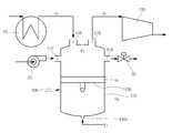
도 1은 본 발명의 일 실시 예에 따른 작동 유체 공급 제어 장치가 적용된 발전 사이클의 일 예를 도시한 모식도이다.1 is a schematic diagram showing an example of a power generation cycle to which a working fluid supply control device according to an embodiment of the present invention is applied.
도 1에 도시된 바와 같이, 작동 유체 공급 제어 장치가 적용된 발전 사이클은 하나의 터빈과 복수의 리큐퍼레이터(200), 복수의 외부 열교환기(300)를 구비한 초임계 이산화탄소 발전 사이클일 수 있다.1, the power generation cycle to which the working fluid supply control device is applied may be a supercritical carbon dioxide power generation cycle having one turbine, a plurality of
본 발명의 각 구성들은 작동 유체가 흐르는 이송관에 의해 연결되며, 특별히 언급하지 않더라도 작동 유체는 이송관을 따라 유동하는 것으로 이해되어야 한다. 다만, 복수 개의 구성들이 일체화 되어 있는 경우, 일체화된 구성 내에 사실상 이송관의 역할을 하는 부품 내지 영역이 있을 것이므로, 이 경우에도 당연히 작동 유체는 이송관을 따라 유동하는 것으로 이해되어야 한다(본 발명에서 이송관은 괄호 안의 숫자로 표기하기로 한다).It is to be understood that each configuration of the present invention is connected by a transfer pipe through which the working fluid flows, and that the working fluid flows along the transfer pipe even if not specifically mentioned. However, in the case where a plurality of structures are integrated, it is to be understood that, in this case, the working fluid flows along the conveyance pipe, as there will be a part or region which actually acts as a conveyance pipe in the integrated structure Pipelines shall be numbered in parentheses).
작동 유체 공급 제어 장치를 통해 사이클 내로 공급된 작동 유체는 압축기(100)에서 고압으로 압축되며, 일부는 리큐퍼레이터(200)로 분기되고 일부는 외부 열교환기(300)로 분기된다.The working fluid supplied into the cycle through the working fluid supply control device is compressed to a high pressure in the
리큐퍼레이터(200)는 제1 리큐퍼레이터(210) 및 제2 리큐퍼레이터(230)로 구성되며, 이들은 직렬로 배치되어 제1 리큐퍼레이터(210)를 통과한 작동 유체가 제2 리큐퍼레이터(230)로 순차적으로 유입된다. 터빈(400)을 통과한 작동 유체가 제1 리큐퍼레이터(210)로 먼저 유입되므로, 제1 리큐퍼레이터(210)는 제2 리큐퍼레이터(230)에 비해 상대적으로 고온의 작동 유체와 열교환을 하게 된다.The
외부 열교환기(300)는 제1 열교환기(310) 및 제2 열교환기(330)로 구성된다. 제1 및 제2 열교환기(310, 330)는 발전소의 보일러에서 배출되는 배기 가스와 같이 폐열을 갖는 기체(이하 폐열 기체)를 열원으로 사용하며, 폐열 기체와 사이클 내를 순환하는 작동 유체와 열교환하여 폐열 기체로부터 공급된 열로 작동 유체를 가열하는 역할을 한다.The
복수의 열교환기(300)가 구비되는 경우, 폐열 기체의 온도에 따라 상대적으로 저온, 중온, 고온 등으로 구분할 수 있다. 즉, 열교환기는 폐열 기체가 유입되는 입구단 쪽에 가까울수록 고온에서의 열교환이 가능하고, 폐열 기체가 배출되는 출구단 쪽에 가까울수록 저온에서의 열교환이 된다.When a plurality of
본 실시 예에서 제1 열교환기(310)는 제2 열교환기(330)에 비해 상대적으로 고온 또는 중온의 폐열 기체를 사용하는 열교환기이고, 제2 열교환기(330)는 상대적으로 중온 또는 저온인 폐열 기체를 사용하는 열교환기일 수 있다. 즉, 폐열 기체가 유입되는 입구단에서 배출단 쪽으로 제1 열교환기(310), 제2 열교환기(330)가 순차적으로 배치된 것을 예로 하여 설명하기로 한다.In the present embodiment, the
전술한 바와 같이, 압축기(100)를 거친 작동 유체의 일부는 제2 리큐퍼레이터(230)로 보내져 제1 리큐퍼레이터(210)를 거친 작동 유체와 열교환해 1차로 가열된 후 제1 리큐퍼레이터(210)로 보내져 터빈(400)을 거친 작동 유체와 열교환해 가열된다. 그 후 제1 열교환기(310)의 전단으로 이송된다.As described above, part of the working fluid that has passed through the
압축기(100)를 거친 작동 유체의 일부는 제2 열교환기(330)로 보내져 폐열 기체와 열교환해 1차로 가열된 후 제1 리큐퍼레이터(210)에서 가열된 작동 유체와 혼합되어 제1 열교환기(310)로 보내진다. 제1 열교환기(310)에서 가열된 작동 유체는 터빈(400)으로 공급된다.A part of the working fluid passing through the
터빈(400)은 작동 유체에 의해 구동되며, 터빈(400)에는 발전기(미도시)가 연결되어 터빈에 의해 전력을 생산할 수 있다. 터빈(400)을 통과하면서 작동 유체가 팽창되므로 터빈(400)은 팽창기(expander)의 역할도 하게 된다. 터빈(400)을 거친 작동 유체는 제1 리큐퍼레이터(210)로 이송된다.The
제1 리큐퍼레이터(210) 및 제2 리큐퍼레이터(230)에서 압축기(100)를 통과한 작동 유체와 열교환해 냉각된 작동 유체는 프리 쿨러(50)로 이송된다.The working fluid that has been heat-exchanged with the working fluid that has passed through the
프리 쿨러(50)는 공기 또는 냉각수를 냉매로 사용해 리큐퍼레이터(200)를 통과하고 1차로 냉각된 작동 유체를 2차로 냉각시킨다. 프리 쿨러(50)를 거쳐 냉각된 작동 유체는 플로테이션 탱크(flotation tank, 500)를 거쳐 압축기(100)로 공급된다.The precooler (50) uses air or cooling water as a refrigerant to pass through the recuperator (200) and cool the primary cooling fluid secondarily. The working fluid cooled through the pre-cooler 50 is supplied to the
압축기(100)로 작동 유체를 공급하기 위한 작동 유체공급 제어 장치는 전술한 프리 쿨러(50)와 압축기(100)의 사이에 배치되는 플로테이션 탱크(500)와, 작동 유체의 저장을 위한 저장 탱크(10)와, 저장 탱크(10)로부터 작동 유체를 플로테이션 탱크(500)로 공급하는 공급 펌프(20)와, 플로테이션 탱크(500)의 작동 유체를 저장 탱크(10)로 배출하기 위한 제어 밸브(30)를 포함하여 구성된다.The working fluid supply control device for supplying the working fluid to the
저장 탱크(10)는 사이클 전체에 필요한 작동 유체의 유량을 저장 및 공급할 수 있는 대용량 저장기로, 최소한 사이클 초기 구동 시 필요한 작동 유체의 양을 저장할 수 있을 정도의 크기를 갖는다. 저장 탱크(10)는 사이클 내에서 작동 유체의 일부 유량을 빼 줄 때에도 사용되므로 사이클의 총 작동 유체의 유량보다 큰 유량을 저장할 수 있는 것이 바람직하다. 저장 탱크(10)에서 플로테이션 탱크(500)로 공급되는 작동 유체의 압력은 공급 펌프(20)에 의해 1차로 승압되며, 플로테이션 탱크(500) 내에서 2차로 제어되어 압축기(100)로 공급될 수 있다.The
플로테이션 탱크(500)는 압축기(100) 입구단에 설치되므로 압축기(100) 입구의 압력 변화에 대한 버퍼 작용을 하게 된다. 따라서 압축기(100) 입구의 압력 제어는 플로테이션 탱크(500)에 의해 자동으로 제어될 수 있다.Since the
압축기(100) 입구의 압력 변화에 대한 버퍼 작용은 플로테이션 탱크(500) 내의 압력변화에 대한 버퍼 작용을 통해 이루어지며, 이를 위해 플로테이션 탱크(500)는 피스톤 축압기(accumulator) 타입의 탱크로 구비되는 것이 바람직하다. 플로테이션 탱크(500)의 최대 허용 flow rate는 예를 들어 215L/sec일 수 있다. 피스톤 축압기 타입의 탱크는 제어 반응의 응답 속도 및 반응 시간이 매우 빠른 장점이 있다.The buffering effect on the pressure change at the inlet of the
플로테이션 탱크(500)가 압축기(100) 입구단에 설치되므로 압축되기 이전의 작동 유체를 일시 저장 또는 유동시키게 된다. 따라서 플로테이션 탱크(500)는 사이클 내의 저압 라인에 위치하게 되어 종래의 인벤토리 탱크와 같이 고압에 견디는 고가의 재질 및 부품을 필요로하지 않아 경제적인 사이클 구성이 가능한 장점이 있다.Since the
저장 탱크(10)가 사이클 전체에서 필요로하는 작동 유체의 유량을 저장할 수 있을 정도의 최소 크기를 가져야 하는데 비해, 플로테이션 탱크(500)는 압력 버퍼 기능을 위해 전체 사이클 유량의 1/3 정도의 작동 유체를 저장할 수 있으면 충분하다. 따라서 종래의 인벤토리 탱크에 비해 1/3까지 플로테이션 탱크(500)의 크기를 축소할 수 있으므로 사이클 구성 비용을 감축할 수 있는 효과가 있다.The
플로테이션 탱크(500)의 압력 버퍼 기능에 대해 상세히 설명하면 다음과 같다.The pressure buffer function of the
도 2는 도 1에 따른 작동 유체 공급 제어 장치의 일 예를 도시한 모식도, 도 3 및 도 4는 도 2에 따른 작동 유체 공급 제어 장치의 작동 상태를 도시한 모식도이다.Fig. 2 is a schematic diagram showing an example of the working fluid supply control device according to Fig. 1, and Figs. 3 and 4 are schematic diagrams showing an operating state of the working fluid supply control device according to Fig.
도 2에 도시된 바와 같이, 플로테이션 탱크(500)는 탱크 본체(510)와, 탱크 본체(510)의내부에 설치된 피스톤(530)과, 탱크 본체(510)의 하단에 형성되어 피스톤(530)을 승강시키는 피스톤 위치 제어용 유체가 유출입하는 제어 유체 유입부(510a)와, 탱크 본체(510)의 일측에 구비되어 공급 펌프(20)로부터 작동 유체가 유입되는 제1 입구(512)와, 탱크 본체(510)의 타측에 구비되어 제어 밸브(30)로 작동 유체가 배출되는 제1 출구(514)가 구비된다. 또한, 제1 입구(512) 및 제1 출구(514)와 이격된 탱크 본체(510)의 상부에는 프리 쿨러(50)로부터 작동 유체가 유입되는 제2 입구(516)와, 제2 입구(516)와 이격되며 압축기(100)로 작동 유체가 배출되는 제2 출구(518)가 구비된다.2, the
도 2에서 P1은 프리 쿨러(50) 후단에서의 압력이고, P2는 압축기(100) 전단에서의 압력이며, Ps는 플로테이션 탱크(500) 내의 압력을 의미한다. 또한, F1은 피스톤(530)의 위치를 제어하기 위한 제어 유체의 유량을 의미한다(사이클 내로 공급되는 작동 유체와 별개의 유체이며, 초임계 이산화탄소가 아닌 다른 작동 유체가 사용될 수 있다). Hs는 플로테이션 탱크(500) 내 설정 포인트에 따른 피스톤(530)의 높이이며, HA는 플로테이션 탱크(500) 내의 압력 변화에 따른 피스톤(530)의 높이를 의미한다. Ps 및 Hs는 사이클의 설계 시 미리 설정된 설정값으로 세팅되며, 압력 변화에 따라 플로테이션 탱크(500) 내 이러한 설정값이 유지되도록 제어된다. 이상을 참조하여 압력 변화에 따른 플로테이션 탱크(500)의 제어 방법에 대해 상세히 설명하기로 한다.In Fig. 2, P1 is the pressure at the rear end of the
도 3에 도시된 바와 같이, P1이 높아지는 경우가 발생할 수 있다.As shown in FIG. 3, a case where P1 is increased may occur.
P1이 상승하면, 플로테이션 탱크(500) 내에서 피스톤(530)의 높이가 Hs에서 HA로 하강하게 된다. 이때, 플로테이션 탱크(500) 내 설정 높이 Hs까지 피스톤(530)을 상승시킴과 동시에 기준 압력 Ps를 유지키기 위해 F1으로 제어 유체의 유량을 주입시키게 된다. 동시에 제어 밸브(30)를 열어 플로테이션 탱크(500) 내의 일부 작동 유체의 유량을 배출해 저장 탱크(10)로 보낸다. 이러한 과정에 따라 Ps 및 Hs가 설정값으로 유지될 때 제어 밸브(30)를 닫아 플로테이션 탱크(500)로부터 작동 유체의 배출을 중지함과 동시에 F1으로의 제어 유체 유량 주입을 중지한다. 이때 공급 펌프(20)는 구동되지 않는다.When P1 rises, the height of the
한편, P2가 높아지는 경우가 발생해도 도 3에 도시된 바와 같이 피스톤(530)이 HA의 높이로 하강할 수 있다. 이 경우에도 플로테이션 탱크(500) 내에서 피스톤(530)의 높이가 Hs에서 HA로 하강하게 된다. 따라서 F1으로 제어 유체를 주입해 기준 압력 Ps를 유지하고 Hs까지 피스톤(530)을 상승시킬 수 있도록 제어 밸브(30)를 열어 플로테이션 탱크(500) 내의 일부 작동 유체를 저장 탱크(10)로 배출한다. Ps 및 Hs가 설정값으로 유지될 때 제어 밸브(30)를 닫아 플로테이션 탱크(500)로부터 작동 유체의 배출을 중지함과 동시에 F1으로의 제어 유체 유량 주입을 중지한다.On the other hand, even if P2 increases, the
반대로 도 4에 도시된 바와 같이, P1이 낮아지는 경우가 발생할 수 있다.Conversely, as shown in FIG. 4, it may happen that P1 is lowered.
P1이 감소하면, 플로테이션 탱크(500) 내에서 피스톤(530)의 높이가 Hs에서 HA로 상승하게 된다. 이때, 플로테이션 탱크(500) 내 설정 높이 Hs까지 피스톤(530)을 하강시킴과 동시에 기준 압력 Ps를 유지키기 위해 공급 펌프(20)를 작동시켜 플로테이션 탱크(500) 내로 작동 유체의 유량을 보충한다. 이러한 과정에 따라 Ps 및 Hs가 설정값이 되면 공급 펌프(20)를 정지시켜 플로테이션 탱크(500)로의 작동 유체의 공급을 중지하여 Ps 및 Hs를 유지한다. 이때 제어 밸브(30)는 구동되지 않으며, 피스톤(530)의 위치 설정을 위한 제어 유체 역시 공급되지 않는다.When P1 decreases, the height of the
또한, P2가 낮아지는 경우가 발생해도 도 4에 도시된 바와 같이 피스톤(530)이 HA의 높이로 상승할 수 있다. 따라서 플로테이션 탱크(500) 내 설정 높이 Hs까지 피스톤(530)을 하강시킴과 동시에 기준 압력 Ps를 유지키기 위해 공급 펌프(20)를 작동시켜 플로테이션 탱크(500) 내로 작동 유체의 유량을 보충한다. 이러한 과정에 따라 Ps 및 Hs가 설정값이 되면 공급 펌프(20)를 정지시켜 플로테이션 탱크(500)로의 작동 유체의 공급을 중지해 Ps 및 Hs를 유지한다.Also, even if P2 is lowered, the
전술한 바와 같이, 압축기 입구 및 프리 쿨러 출구의 압력 변화에 따라 플로테이션 탱크 내의 압력 및 작동 유체 유량이 가변되므로 플로테이션 탱크 내 압력 및 피스톤의 높이가 일정 설정값으로 유지될 수 있다. 이와 같이 플로테이션 탱크가 압축기 입구의 압력 변화에 따른 버퍼 역할을 하므로 별도의 압력 제어가 필요하지 않아 종래의 인벤토리 탱크와 같은 고가의 재질 및 부품을 사용하지 않아도 되므로 사이클 구성 비용이 절감되는 효과가 있다. 또한, 플로테이션 탱크만으로 작동 유체의 유량을 효율적으로 제어할 수 있고, 압축기 입출구의 압력을 제어할 수 있어 사이클 구성 비용의 절감과 더불어 경제성이 향상되는 효과가 있다.As described above, since the pressure in the floatation tank and the flow rate of the working fluid are varied according to the pressure change at the compressor inlet and the precooler outlet, the pressure in the floatation tank and the height of the piston can be maintained at a predetermined set value. Since the fluidization tank functions as a buffer according to the pressure change at the inlet of the compressor, no additional pressure control is required, so that it is not necessary to use expensive materials and parts such as the conventional inventory tanks, thereby reducing the cycle construction cost . Further, the flow rate of the working fluid can be efficiently controlled by only the floatation tank, and the pressure at the inlet and outlet of the compressor can be controlled, thereby reducing the cycle construction cost and improving the economical efficiency.
앞에서 설명되고 도면에 도시된 본 발명의 일 실시 예는, 본 발명의 기술적 사상을 한정하는 것으로 해석되어서는 안 된다. 본 발명의 권리범위는 청구범위에 기재된 사항에 의해서만 제한되고, 본 발명의 기술분야에서 통상의 지식을 가진 자는 본 발명의 기술적 사상을 다양한 형태로 개량 및 변경하는 것이 가능하다. 따라서 이러한 개량 및 변경이 통상의 지식을 가진 자에게 자명한 것인 한, 본 발명의 권리범위에 속하게 될 것이다.One embodiment of the present invention described above and shown in the drawings should not be construed as limiting the technical spirit of the present invention. The scope of the present invention is limited only by the matters described in the claims, and those skilled in the art can improve and modify the technical spirit of the present invention in various forms. Accordingly, it is intended that the present invention cover the modifications and variations of this invention provided they come within the scope of the appended claims and their equivalents.
10: 저장 탱크20: 공급 펌프
30: 제어 밸브50: 프리 쿨러
100: 압축기200: 리큐퍼레이터
300: 열교환기400: 터빈
500: 플로테이션 탱크10: Storage tank 20: Feed pump
30: control valve 50: pre-cooler
100: compressor 200: recuperator
300: heat exchanger 400: turbine
500: floatation tank
Claims (20)
Translated fromKorean상기 발전 사이클로 공급되는 상기 작동 유체를 저장하는 저장 탱크와,
상기 프리 쿨러와 상기 압축기의 사이에 배치되어 상기 작동 유체가 유동하거나 일시 저장되는 플로테이션 탱크를 포함하며,
상기 압축기 입구 및 상기 프리 쿨러의 출구의 압력에 따라 상기 플로테이션 탱크 내 압력 및 상기 작동 유체의 유량이 제어되는 것을 특징으로 하는 작동 유체 공급 제어 장치.1. A working fluid supply control device for supplying a working fluid to a power generation cycle having a compressor for compressing a working fluid and a precooler for cooling a working fluid supplied to the compressor,
A storage tank for storing the working fluid supplied to the power generation cycle;
And a floatation tank disposed between the pre-cooler and the compressor, wherein the working fluid flows or temporarily stored,
Wherein the pressure in the floatation tank and the flow rate of the working fluid are controlled in accordance with the pressures at the compressor inlet and the outlet of the precooler.
상기 저장 탱크와 상기 플로테이션 탱크의 사이에 구비되어 상기 저장 탱크로부터 상기 작동 유체를 상기 플로테이션 탱크로 공급하는 공급 펌프와, 상기 저장 탱크와 상기 플로테이션 탱크의 사이에 구비되어 상기 플로테이션 탱크로부터 상기 작동 유체를 상기 저장 탱크로 배출하기 위한 제어 밸브를 더 포함하는 작동 유체 공급 제어 장치.The method according to claim 1,
A supply pump provided between the storage tank and the floatation tank for supplying the working fluid from the storage tank to the floatation tank and a supply pump provided between the storage tank and the floatation tank, And a control valve for discharging the working fluid to the storage tank.
상기 플로테이션 탱크는 피스톤 축압기(accumulator) 타입의 탱크인 것을 특징으로 하는 작동 유체 공급 제어 장치.3. The method of claim 2,
Wherein the floatation tank is a tank accumulator type tank.
상기 플로테이션 탱크는 상기 작동 유체가 유입되는 탱크 본체와, 상기 탱크 본체의 내부에 설치 외부에서 공급되는 제어용 유체에 의해 승강하는 피스톤을 포함하는 작동 유체 공급 제어 장치.The method of claim 3,
Wherein the fluidization tank includes a tank body into which the working fluid flows and a piston which moves up and down by a control fluid supplied from the outside in the tank body.
상기 플로테이션 탱크는 상기 탱크 본체의 하단에 구비되어 상기 제어용 유체가 유출입하는 제어 유체 유입부와, 상기 탱크 본체의 일측에 구비되어 상기 공급 펌프로부터 상기 작동 유체가 유입되는 제1 입구와, 상기 탱크 본체의 타측에 구비되어 상기 제어 밸브로 상기 작동 유체가 배출되는 제1 출구를 더 포함하는 작동 유체 공급 제어 장치.5. The method of claim 4,
The control fluid flowing in and flowing out of the control fluid is provided at a lower end of the tank main body, a first inlet provided at one side of the tank main body and through which the working fluid flows from the supply pump, And a first outlet provided on the other side of the main body for discharging the working fluid to the control valve.
상기 플로테이션 탱크는 상기 탱크 본체의 상부에 구비되어 상기 프리 쿨러로부터 상기 작동 유체가 유입되는 제2 입구와, 상기 탱크 본체의 상부에 구비되어 상기 압축기로 상기 작동 유체가 배출되는 제2 출구를 더 포함하는 작동 유체 공급 제어 장치.6. The method of claim 5,
And a second outlet provided at an upper portion of the tank main body and through which the working fluid is discharged by the compressor, the second inlet being provided at an upper portion of the tank main body and through which the working fluid flows from the precooler, And a working fluid supply control device.
상기 프리 쿨러 후단에서의 압력인 P1 또는 상기 압축기 전단에서의 압력인 P2가 높아지는 경우, 상기 제어 유체 유입부로 상기 제어용 유체가 공급되고, 상기 제어 밸브를 개방해 상기 제1 출구를 통해 상기 플로테이션 탱크 내의 작동 유체를 상기 저장 탱크로 배출하는 것을 특징으로 하는 작동 유체 공급 제어 장치.The method according to claim 6,
Wherein the control fluid is supplied to the control fluid inlet when the pressure P1 at the rear end of the precooler or the pressure P2 at the front end of the compressor becomes high and the control fluid is supplied to the control fluid inlet through the first outlet, And discharges the working fluid in the storage tank to the storage tank.
상기 제어용 유체의 공급 및 상기 저장 탱크로의 상기 작동 유체의 배출은 상기 피스톤의 높이가 설정값에 대응하는 높이에 도달할 때까지 이루어지는 것을 특징으로 하는 작동 유체 공급 제어 장치.8. The method of claim 7,
Wherein supply of the control fluid and discharge of the working fluid to the storage tank are performed until the height of the piston reaches a height corresponding to the set value.
상기 프리 쿨러 후단에서의 압력인 P1 또는 상기 압축기 전단에서의 압력인 P2가 낮아지는 경우, 상기 공급 펌프를 작동해 상기 제1 입구를 통해 상기 플로테이션 탱크 내로 상기 작동 유체를 공급하는 것을 특징으로 하는 작동 유체 공급 제어 장치.The method according to claim 6,
Wherein when the pressure P1 at the rear end of the pre-cooler or the pressure P2 at the front end of the compressor is lowered, the supply pump is operated to supply the working fluid into the floatation tank through the first inlet Operating fluid supply control device.
상기 플로테이션 탱크 내로의 상기 작동 유체의 공급은 상기 피스톤의 높이가 설정값에 대응하는 높이에 도달할 때까지 이루어지는 것을 특징으로 하는 작동 유체 공급 제어 장치.10. The method of claim 9,
Wherein supply of the working fluid into the tank is performed until a height of the piston reaches a height corresponding to a set value.
상기 발전 사이클로 공급되는 상기 작동 유체를 저장하는 저장 탱크와,
상기 압축기의 입구 저압 라인에 배치되어 상기 작동 유체가 유동하거나 일시 저장되는 플로테이션 탱크와,
상기 저장 탱크와 상기 플로테이션 탱크의 사이에 구비되어 상기 저장 탱크로부터 상기 작동 유체를 상기 플로테이션 탱크로 공급하는 공급 펌프와, 상기 저장 탱크와 상기 플로테이션 탱크의 사이에 구비되어 상기 플로테이션 탱크로부터 상기 작동 유체를 상기 저장 탱크로 배출하기 위한 제어 밸브를 포함하는 작동 유체 공급 제어 장치.1. A working fluid supply control device for supplying a working fluid to a power generation cycle having a compressor for compressing a working fluid and a precooler for cooling a working fluid supplied to the compressor,
A storage tank for storing the working fluid supplied to the power generation cycle;
A floatation tank disposed in an inlet low-pressure line of the compressor, for flowing or temporarily storing the working fluid;
A supply pump provided between the storage tank and the floatation tank for supplying the working fluid from the storage tank to the floatation tank and a supply pump provided between the storage tank and the floatation tank, And a control valve for discharging the working fluid to the storage tank.
상기 프리 쿨러의 출구 또는 상기 압축기 입구의 압력이 높아지면 상기 플로테이션 탱크로부터 상기 작동 유체를 상기 저장 탱크로 배출시키고, 상기 프리 쿨러의 출구 또는 상기 압축기 입구의 압력이 낮아지면 상기 저장 탱크로부터 상기 플로테이션 탱크로 상기 작동 유체를 공급하는 것을 특징으로 하는 작동 유체 공급 제어 장치.12. The method of claim 11,
The control unit discharges the working fluid from the storage tank to the storage tank when the outlet of the pre-cooler or the pressure of the compressor inlet becomes high. When the pressure of the outlet of the pre-cooler or the inlet of the compressor becomes low, And the working fluid is supplied to the working tank by the working tank.
상기 플로테이션 탱크는 피스톤 축압기(accumulator) 타입의 탱크인 것을 특징으로 하는 작동 유체 공급 제어 장치.13. The method of claim 12,
Wherein the floatation tank is a tank accumulator type tank.
상기 플로테이션 탱크는 상기 작동 유체가 유입되는 탱크 본체와, 상기 탱크 본체의 내부에 설치 외부에서 공급되는 제어용 유체에 의해 승강하는 피스톤을 포함하는 작동 유체 공급 제어 장치.14. The method of claim 13,
Wherein the fluidization tank includes a tank body into which the working fluid flows and a piston which moves up and down by a control fluid supplied from the outside in the tank body.
상기 플로테이션 탱크는 상기 탱크 본체의 하단에 구비되어 상기 제어용 유체가 유출입하는 제어 유체 유입부와, 상기 탱크 본체의 일측에 구비되어 상기 공급 펌프로부터 상기 작동 유체가 유입되는 제1 입구와, 상기 탱크 본체의 타측에 구비되어 상기 제어 밸브로 상기 작동 유체가 배출되는 제1 출구를 더 포함하는 작동 유체 공급 제어 장치.15. The method of claim 14,
The control fluid flowing in and flowing out of the control fluid is provided at a lower end of the tank main body, a first inlet provided at one side of the tank main body and through which the working fluid flows from the supply pump, And a first outlet provided on the other side of the main body for discharging the working fluid to the control valve.
상기 플로테이션 탱크는 상기 탱크 본체의 상부에 구비되어 상기 프리 쿨러로부터 상기 작동 유체가 유입되는 제2 입구와, 상기 탱크 본체의 상부에 구비되어 상기 압축기로 상기 작동 유체가 배출되는 제2 출구를 더 포함하는 작동 유체 공급 제어 장치.16. The method of claim 15,
And a second outlet provided at an upper portion of the tank main body and through which the working fluid is discharged by the compressor, the second inlet being provided at an upper portion of the tank main body and through which the working fluid flows from the precooler, And a working fluid supply control device.
상기 프리 쿨러 후단에서의 압력인 P1 또는 상기 압축기 전단에서의 압력인 P2가 높아지는 경우, 상기 제어 유체 유입부로 상기 제어용 유체가 공급되고, 상기 제어 밸브를 개방해 상기 제1 출구를 통해 상기 플로테이션 탱크 내의 작동 유체를 상기 저장 탱크로 배출하는 것을 특징으로 하는 작동 유체 공급 제어 장치.17. The method of claim 16,
Wherein the control fluid is supplied to the control fluid inlet when the pressure P1 at the rear end of the precooler or the pressure P2 at the front end of the compressor becomes high and the control fluid is supplied to the control fluid inlet through the first outlet, And discharges the working fluid in the storage tank to the storage tank.
상기 제어용 유체의 공급 및 상기 저장 탱크로의 상기 작동 유체의 배출은 상기 피스톤의 높이가 설정값에 대응하는 높이에 도달할 때까지 이루어지는 것을 특징으로 하는 작동 유체 공급 제어 장치.18. The method of claim 17,
Wherein supply of the control fluid and discharge of the working fluid to the storage tank are performed until the height of the piston reaches a height corresponding to the set value.
상기 프리 쿨러 후단에서의 압력인 P1 또는 상기 압축기 전단에서의 압력인 P2가 낮아지는 경우, 상기 공급 펌프를 작동해 상기 제1 입구를 통해 상기 플로테이션 탱크 내로 상기 작동 유체를 공급하는 것을 특징으로 하는 작동 유체 공급 제어 장치.17. The method of claim 16,
Wherein when the pressure P1 at the rear end of the pre-cooler or the pressure P2 at the front end of the compressor is lowered, the supply pump is operated to supply the working fluid into the floatation tank through the first inlet Operating fluid supply control device.
상기 플로테이션 탱크 내로의 상기 작동 유체의 공급은 상기 피스톤의 높이가 설정값에 대응하는 높이에 도달할 때까지 이루어지는 것을 특징으로 하는 작동 유체 공급 제어 장치.20. The method of claim 19,
Wherein supply of the working fluid into the tank is performed until a height of the piston reaches a height corresponding to a set value.
Priority Applications (3)
| Application Number | Priority Date | Filing Date | Title |
|---|---|---|---|
| KR1020170039383AKR101868273B1 (en) | 2017-03-28 | 2017-03-28 | Control device for suppling of working fluid |
| US15/927,097US10385737B2 (en) | 2017-03-28 | 2018-03-21 | Device for controlling supply of working fluid |
| JP2018057234AJP6603948B2 (en) | 2017-03-28 | 2018-03-23 | Working fluid supply control device |
Applications Claiming Priority (1)
| Application Number | Priority Date | Filing Date | Title |
|---|---|---|---|
| KR1020170039383AKR101868273B1 (en) | 2017-03-28 | 2017-03-28 | Control device for suppling of working fluid |
Publications (1)
| Publication Number | Publication Date |
|---|---|
| KR101868273B1true KR101868273B1 (en) | 2018-06-15 |
Family
ID=62628711
Family Applications (1)
| Application Number | Title | Priority Date | Filing Date |
|---|---|---|---|
| KR1020170039383AActiveKR101868273B1 (en) | 2017-03-28 | 2017-03-28 | Control device for suppling of working fluid |
Country Status (3)
| Country | Link |
|---|---|
| US (1) | US10385737B2 (en) |
| JP (1) | JP6603948B2 (en) |
| KR (1) | KR101868273B1 (en) |
Cited By (1)
| Publication number | Priority date | Publication date | Assignee | Title |
|---|---|---|---|---|
| KR20200018323A (en)* | 2018-08-09 | 2020-02-19 | 포르시아 쥐스뗌 데샤피망 | Thermal system with rankine circuit |
Families Citing this family (6)
| Publication number | Priority date | Publication date | Assignee | Title |
|---|---|---|---|---|
| EP3935266A4 (en)* | 2019-03-06 | 2023-04-05 | Industrom Power, LLC | Intercooled cascade cycle waste heat recovery system |
| CA3140746A1 (en)* | 2019-05-17 | 2020-11-26 | 8 Rivers Capital, Llc | Closed cycle inventory control |
| WO2021086989A1 (en)* | 2019-10-28 | 2021-05-06 | Peregrine Turbine Technologies, Llc | Methods and systems for starting and stopping a closed-cycle turbomachine |
| US20240142143A1 (en)* | 2022-10-27 | 2024-05-02 | Supercritical Storage Company, Inc. | High-temperature, dual rail heat pump cycle for high performance at high-temperature lift and range |
| CN115387867B (en)* | 2022-10-31 | 2023-03-24 | 中国核动力研究设计院 | Power generation system and working medium loading method based on power generation system |
| WO2025010090A1 (en) | 2023-02-07 | 2025-01-09 | Supercritical Storage Company, Inc. | Waste heat integration into pumped thermal energy storage |
Citations (4)
| Publication number | Priority date | Publication date | Assignee | Title |
|---|---|---|---|---|
| KR100774568B1 (en)* | 2007-09-10 | 2007-11-08 | 황창성 | Hydraulic Turbine Valve Control |
| US8281593B2 (en) | 2009-09-17 | 2012-10-09 | Echogen Power Systems, Inc. | Heat engine and heat to electricity systems and methods with working fluid fill system |
| JP2013545930A (en)* | 2010-12-16 | 2013-12-26 | ダイムラー・アクチェンゲゼルシャフト | Waste heat recovery device, operating method |
| JP2015203417A (en)* | 2014-04-16 | 2015-11-16 | イエフペ エネルジ ヌヴェルIfp Energies Nouvelles | Device for controlling closed loop working based on rankine cycle and method using the same |
Family Cites Families (8)
| Publication number | Priority date | Publication date | Assignee | Title |
|---|---|---|---|---|
| US4765143A (en)* | 1987-02-04 | 1988-08-23 | Cbi Research Corporation | Power plant using CO2 as a working fluid |
| US8613195B2 (en)* | 2009-09-17 | 2013-12-24 | Echogen Power Systems, Llc | Heat engine and heat to electricity systems and methods with working fluid mass management control |
| JP5834538B2 (en)* | 2011-06-27 | 2015-12-24 | 株式会社Ihi | Waste heat generator |
| US20140102098A1 (en)* | 2012-10-12 | 2014-04-17 | Echogen Power Systems, Llc | Bypass and throttle valves for a supercritical working fluid circuit |
| JP2014134175A (en) | 2013-01-11 | 2014-07-24 | Toyota Industries Corp | Rankine cycle device |
| JP6038671B2 (en)* | 2013-02-01 | 2016-12-07 | 三菱日立パワーシステムズ株式会社 | Thermal power generation system |
| US10077683B2 (en)* | 2013-03-14 | 2018-09-18 | Echogen Power Systems Llc | Mass management system for a supercritical working fluid circuit |
| WO2016099975A1 (en)* | 2014-12-18 | 2016-06-23 | Echogen Power Systems, L.L.C. | Passive alternator depressurization and cooling system |
- 2017
- 2017-03-28KRKR1020170039383Apatent/KR101868273B1/enactiveActive
- 2018
- 2018-03-21USUS15/927,097patent/US10385737B2/enactiveActive
- 2018-03-23JPJP2018057234Apatent/JP6603948B2/enactiveActive
Patent Citations (4)
| Publication number | Priority date | Publication date | Assignee | Title |
|---|---|---|---|---|
| KR100774568B1 (en)* | 2007-09-10 | 2007-11-08 | 황창성 | Hydraulic Turbine Valve Control |
| US8281593B2 (en) | 2009-09-17 | 2012-10-09 | Echogen Power Systems, Inc. | Heat engine and heat to electricity systems and methods with working fluid fill system |
| JP2013545930A (en)* | 2010-12-16 | 2013-12-26 | ダイムラー・アクチェンゲゼルシャフト | Waste heat recovery device, operating method |
| JP2015203417A (en)* | 2014-04-16 | 2015-11-16 | イエフペ エネルジ ヌヴェルIfp Energies Nouvelles | Device for controlling closed loop working based on rankine cycle and method using the same |
Cited By (3)
| Publication number | Priority date | Publication date | Assignee | Title |
|---|---|---|---|---|
| KR20200018323A (en)* | 2018-08-09 | 2020-02-19 | 포르시아 쥐스뗌 데샤피망 | Thermal system with rankine circuit |
| US11028756B2 (en) | 2018-08-09 | 2021-06-08 | Faurecia Systemes D'echappement | Thermal system with rankine circuit |
| KR102315299B1 (en)* | 2018-08-09 | 2021-10-19 | 포르시아 쥐스뗌 데샤피망 | Thermal system with rankine circuit |
Also Published As
| Publication number | Publication date |
|---|---|
| JP2018165511A (en) | 2018-10-25 |
| US10385737B2 (en) | 2019-08-20 |
| JP6603948B2 (en) | 2019-11-13 |
| US20180283222A1 (en) | 2018-10-04 |
Similar Documents
| Publication | Publication Date | Title |
|---|---|---|
| KR101868273B1 (en) | Control device for suppling of working fluid | |
| CN203892027U (en) | Fuel gas heating system with heat energy storage unit | |
| KR101628616B1 (en) | Supercritical CO2 generation system | |
| CN103452612A (en) | Compressed air energy storage system using carbon dioxide as working medium | |
| EP3059415B1 (en) | System and method for heating make-up working fluid of a steam system with engine fluid waste heat | |
| CN104564194B (en) | The waste heat comprehensive utilization system of internal-combustion engine | |
| KR101680963B1 (en) | Supercritical CO2 generation system | |
| CN220929493U (en) | Compressed air energy storage system adopting water side constant-pressure water heat storage mode | |
| CN105156163A (en) | Waste-heat utilization organic Rankine cycle system for fluctuant heat source | |
| KR20180058325A (en) | Supercritical CO2 generation system for parallel recuperative type | |
| KR101628611B1 (en) | Supercritical CO2 generation system using multistage compressing and expanding of working fluid | |
| KR102026327B1 (en) | Hybrid power generating system | |
| JP7103876B2 (en) | Hydrogen shipping equipment and hydrogen shipping system | |
| JPWO2006030779A1 (en) | Heat pump, heat pump system and Rankine cycle | |
| CN114810252A (en) | Supercritical CO 2 Variable-load working medium charging and discharging system and method for generator set | |
| KR20100068568A (en) | Power generation system using waste heat of ship engines | |
| US10202874B2 (en) | Supercritical CO2 generation system applying plural heat sources | |
| CN204457897U (en) | The waste heat comprehensive utilization system of internal-combustion engine | |
| US10202873B2 (en) | Supercritical CO2 generation system applying plural heat sources | |
| US11136898B2 (en) | Sealing gas supply apparatus | |
| KR101838435B1 (en) | Supercritical CO2 generation system and control method thereof | |
| KR101628619B1 (en) | generation system having temperature control device for heat exchanger | |
| KR102021900B1 (en) | Supercritical CO2 generating system and method for operating thereof | |
| KR101868271B1 (en) | Device and method for suppling of working fuid | |
| CN105804817A (en) | Electricity generating system and operation control method thereof |
Legal Events
| Date | Code | Title | Description |
|---|---|---|---|
| PA0109 | Patent application | Patent event code:PA01091R01D Comment text:Patent Application Patent event date:20170328 | |
| PA0201 | Request for examination | ||
| PE0902 | Notice of grounds for rejection | Comment text:Notification of reason for refusal Patent event date:20171230 Patent event code:PE09021S01D | |
| E701 | Decision to grant or registration of patent right | ||
| PE0701 | Decision of registration | Patent event code:PE07011S01D Comment text:Decision to Grant Registration Patent event date:20180531 | |
| GRNT | Written decision to grant | ||
| PR0701 | Registration of establishment | Comment text:Registration of Establishment Patent event date:20180608 Patent event code:PR07011E01D | |
| PR1002 | Payment of registration fee | Payment date:20180608 End annual number:3 Start annual number:1 | |
| PG1601 | Publication of registration | ||
| PR1001 | Payment of annual fee | Payment date:20210401 Start annual number:4 End annual number:4 | |
| PR1001 | Payment of annual fee | Payment date:20230329 Start annual number:6 End annual number:6 |