KR101867424B1 - Wireless power charging apparatus transmitting power wirelessly for drones airborne - Google Patents
Wireless power charging apparatus transmitting power wirelessly for drones airborneDownload PDFInfo
- Publication number
- KR101867424B1 KR101867424B1KR1020180001601AKR20180001601AKR101867424B1KR 101867424 B1KR101867424 B1KR 101867424B1KR 1020180001601 AKR1020180001601 AKR 1020180001601AKR 20180001601 AKR20180001601 AKR 20180001601AKR 101867424 B1KR101867424 B1KR 101867424B1
- Authority
- KR
- South Korea
- Prior art keywords
- wireless
- drones
- charging
- electromagnet
- charging device
- Prior art date
- Legal status (The legal status is an assumption and is not a legal conclusion. Google has not performed a legal analysis and makes no representation as to the accuracy of the status listed.)
- Expired - Fee Related
Links
Images


Classifications
- B—PERFORMING OPERATIONS; TRANSPORTING
- B64—AIRCRAFT; AVIATION; COSMONAUTICS
- B64C—AEROPLANES; HELICOPTERS
- B64C39/00—Aircraft not otherwise provided for
- B64C39/02—Aircraft not otherwise provided for characterised by special use
- B64C39/024—Aircraft not otherwise provided for characterised by special use of the remote controlled vehicle type, i.e. RPV
- B—PERFORMING OPERATIONS; TRANSPORTING
- B64—AIRCRAFT; AVIATION; COSMONAUTICS
- B64D—EQUIPMENT FOR FITTING IN OR TO AIRCRAFT; FLIGHT SUITS; PARACHUTES; ARRANGEMENT OR MOUNTING OF POWER PLANTS OR PROPULSION TRANSMISSIONS IN AIRCRAFT
- B64D47/00—Equipment not otherwise provided for
- B—PERFORMING OPERATIONS; TRANSPORTING
- B64—AIRCRAFT; AVIATION; COSMONAUTICS
- B64U—UNMANNED AERIAL VEHICLES [UAV]; EQUIPMENT THEREFOR
- B64U10/00—Type of UAV
- B64U10/10—Rotorcrafts
- B—PERFORMING OPERATIONS; TRANSPORTING
- B64—AIRCRAFT; AVIATION; COSMONAUTICS
- B64U—UNMANNED AERIAL VEHICLES [UAV]; EQUIPMENT THEREFOR
- B64U50/00—Propulsion; Power supply
- B64U50/10—Propulsion
- B64U50/19—Propulsion using electrically powered motors
- B—PERFORMING OPERATIONS; TRANSPORTING
- B64—AIRCRAFT; AVIATION; COSMONAUTICS
- B64U—UNMANNED AERIAL VEHICLES [UAV]; EQUIPMENT THEREFOR
- B64U50/00—Propulsion; Power supply
- B64U50/30—Supply or distribution of electrical power
- B64U50/34—In-flight charging
- B—PERFORMING OPERATIONS; TRANSPORTING
- B64—AIRCRAFT; AVIATION; COSMONAUTICS
- B64U—UNMANNED AERIAL VEHICLES [UAV]; EQUIPMENT THEREFOR
- B64U70/00—Launching, take-off or landing arrangements
- B64U70/80—Vertical take-off or landing, e.g. using rockets
- H—ELECTRICITY
- H02—GENERATION; CONVERSION OR DISTRIBUTION OF ELECTRIC POWER
- H02J—CIRCUIT ARRANGEMENTS OR SYSTEMS FOR SUPPLYING OR DISTRIBUTING ELECTRIC POWER; SYSTEMS FOR STORING ELECTRIC ENERGY
- H02J50/00—Circuit arrangements or systems for wireless supply or distribution of electric power
- H02J50/10—Circuit arrangements or systems for wireless supply or distribution of electric power using inductive coupling
- H02J50/12—Circuit arrangements or systems for wireless supply or distribution of electric power using inductive coupling of the resonant type
- B64C2201/024—
- B64C2201/042—
- B64C2201/066—
- B64C2201/088—
- B64C2201/12—
- B—PERFORMING OPERATIONS; TRANSPORTING
- B64—AIRCRAFT; AVIATION; COSMONAUTICS
- B64U—UNMANNED AERIAL VEHICLES [UAV]; EQUIPMENT THEREFOR
- B64U2101/00—UAVs specially adapted for particular uses or applications
Landscapes
- Engineering & Computer Science (AREA)
- Aviation & Aerospace Engineering (AREA)
- Chemical & Material Sciences (AREA)
- Combustion & Propulsion (AREA)
- Computer Networks & Wireless Communication (AREA)
- Power Engineering (AREA)
- Mechanical Engineering (AREA)
- Remote Sensing (AREA)
- Charge And Discharge Circuits For Batteries Or The Like (AREA)
Abstract
Translated fromKoreanDescription
Translated fromKorean본 발명은 비행 중인 드론에 무선으로 전력을 전송하는 무선충전장치에 관한 것으로서, 더 상세하게는, 충전을 요하는 드론에 자기 공진 방식으로 전력을 송수신하게 하는 무선충전장치에 관한 것이다.BACKGROUND OF THE
무인비행기는 조종사가 탑승하지 않고 원격 조종 또는 자율비행 제어로 비행하여 촬영, 정찰, 화물 수송, 방사능 감시 등 사람이 직접 수행하기 힘들거나 위험한 임무를 수행하는 비행기를 의미한다. 무인비행기로서, GPS를 이용하여 항행 또는 착륙 유도가 제어되는 드론(drone)이 알려져 있다.Unmanned airplanes are airplanes that perform difficult or dangerous missions, such as shooting, reconnaissance, cargo transportation, and radioactivity surveillance, which can not be carried out by pilots and fly by remote control or autonomous flight control. As a drone, a drone is known in which navigation or landing induction is controlled using GPS.
그런데, 전원으로 배터리를 이용하는 경우 드론의 운행 시간이 제한되므로, 전원 충전을 간헐적 또는 정기적으로 수행하기 충전 방식이 제안되어 왔다. 예를 들어 특허 제1599423호는 충전 배터리를 구비한 드론의 배터리를 충전할 수 있는 충전패드를 가진 복수 개의 충전소를 설치하고, 서버가 충전소의 동작을 제어하도록 한 드론용 무선 충전 플랫폼 시스템을 개시하고 있다. 또 다른 공개 특허 제2017-0049040호는 무인 비행하는 드론의 충전 모듈을 격납고에서 교체할 수 있도록 한 드론 자동 충전 및 격납 시스템을 개시하고 있다.However, since the operating time of the drone is limited when the battery is used as the power source, a charging method for performing the power source charging intermittently or periodically has been proposed. For example, Japanese Patent No. 1599423 discloses a wireless charging platform system for a drones in which a plurality of charging stations having a charging pad capable of charging a battery of a drones equipped with a rechargeable battery are installed and a server controls the operation of the charging station have. Another patent publication No. 2017-0049040 discloses a drone automatic charging and containment system that allows the charging module of the drone to be replaced at the hangar.
그런데 이들 선행기술에서는 드론을 충전하려면 지상의 충전소 또는 격납고에 착륙시켜야 하므로, 이들과 먼 거리에서 비행 중인 드론의 충전이 불편하고, 이동과 착륙에 시간이 소요되어 실제 유효 비행 시간은 단축되어 버리는 문제가 있다. 또, 충전소나 격납고를 지상의 여러 곳에 배치하기 위해 설치 비용이 소요되고, 유지 보수가 번거로운 단점이 있다.However, in the prior art, charging the drone requires landing at a charging station or a hangar on the ground. Therefore, it is inconvenient to charge the drones flying in the distance from them, and it takes time to travel and land, . In addition, there is a disadvantage that installation cost is required to place the charging station or the hangar in various places on the ground, and maintenance is troublesome.
상기와 같이 비행 중인 드론은 배터리에 저장된 전력이 한계가 있어 장거리를 이동하는 데는 어려움이 있는바, 배터리가 거의 소진되어 가는 드론에 배터리가 완충된 다른 드론이 공중에서 충전을 해주는 형태를 상정할 수 있다.As described above, the flying dragon has a limitation in the power stored in the battery, so that it is difficult to move over a long distance. It is possible to assume that the battery is almost exhausted and the other drones charged with the battery charge in the air have.
그러나 상기한 바와 같이 공중에서 충전하는 경우에는 충전 거리에 실질적인 제약이 있는 자기유도 방식은 제한이 있는바, 자기공전 방식으로 무선 전력을 전송하는 것을 검토할 수 있다.However, in the case of charging in the air as described above, there is a limitation in the magnetic induction method in which there is a practical limitation on the charging distance, and it can be considered that the wireless power is transmitted by the self-orbiting method.
한편, 자기공전 방식의 경우에는 드론이 흔들리거나 움직일 때마다 송신기와 수신기 사이의 거리와 위치가 실시간으로 변동하게 되고, 송신기와 수신기의 거리가 변할 때마다 매칭 가능한 임피던스가 변하게 된다는 문제점이 있다.On the other hand, in the case of the magnetostrictive method, the distance and the position between the transmitter and the receiver change in real time every time the dron is shaken or moved, and the matching impedance changes every time the distance between the transmitter and the receiver changes.
상기와 같이, 공중에서 배터리가 완충된 드론과 배터리가 소진 예정인 드론에 각각 장착된 송신기와 수신기의 통신을 통하여 임피던스를 지속적으로 조정해야 하는데, 이러한 방식으로는 효율이 떨어지고 전송에 어려움이 있다는 문제점이 있다.As described above, the impedance needs to be constantly adjusted through the communication between the transmitter and the receiver, which are respectively installed in the air-borne drones and the battery drums that are to be exhausted. In this way, efficiency is low and transmission is difficult have.
본 발명에서는공중에서 드론에 자기 공진 방식으로 전력을 송수신하게 하는 무선충전장치를 제공하는 것을 목적으로 한다.SUMMARY OF THE INVENTION It is an object of the present invention to provide a wireless charging device for transmitting and receiving power to and from a drones in a self-resonant manner.
상기와 같은 목적을 달성하기 위한 본 발명은 공중에서 비행 중인 드론에 무선으로 전력을 전송할 수 있는 무선전력충전장치를 제공한다.According to an aspect of the present invention, there is provided a wireless power charging apparatus capable of wirelessly transmitting power to a drones flying in air.
상기 무선전력충전장치는 본체를 이루는 충전 바디; 상기 충전 바디 상에 배치된 상태에서 연속비행을 가능하게 하는 프로펠러; 상기 충전 바디의 일 측면을 향하도록 구비된 무선 송신기; 및 상기 충전 바디의 일 측면 상에 구비되는 적어도 하나의 전자석;을 포함하고, 상기 전자석과 동일한 배치 구조로 적어도 하나의 자성체를 그 일 측면 상에 구비한 드론이 상기 무선충전장치에 기준 거리 내로 접근하면, 상기 무선충전장치의 전자석 이 작동하여 상기 무선충전장치의 측면과 상기 드론의 측면이 밀착하게 되고, 이후 상기 무선 송신기의 송신 공진 코일에서 상기 드론에 구비된 무선 수신기의 수신 공진 코일로 전력을 전송하여 상기 드론을 충전한다.The wireless power charging apparatus includes: a charging body constituting a main body; A propeller for allowing continuous flight in a deployed state on the charging body; A wireless transmitter arranged to face one side of the charging body; And at least one electromagnet provided on one side of the charging body, wherein a dron having at least one magnetic body on one side thereof in the same arrangement structure as the electromagnet, The electromagnet of the wireless charging device is operated to bring the side surface of the wireless charging device into close contact with the side surface of the dron and then the electric power is supplied from the transmission resonant coil of the radio transmitter to the reception resonant coil of the radio receiver provided in the dron Thereby charging the drones.
상기 드론을 충전할 때, 상기 무선 송신기의 송신 공진 코일과 상기 무선 수신기의 수신 공진 코일은 서로 마주보게 배치되도록 한다.When charging the drones, the transmitting resonant coil of the radio transmitter and the receiving resonant coil of the radio receiver are arranged to face each other.
상기 드론의 자성체에 추가적으로 전선을 권선하여 전자석으로 작동하게 하고, 상기 충전 바디의 일 측면에 구비된 전자석이 작동할 때, 상기 드론의 자성체도 대응되게 작동하여, 상기 충전 바디와 상기 드론이 밀착되게 한다.The magnetic body of the dron also correspondingly operates when the electromagnet provided on one side of the charging body operates so that the charging body and the dron are in close contact with each other, do.
상기 충전 바디의 전자석과 상기 드론의 자성체가 다수 부착될 경우, 상기 전자석과 상기 자성체는 순차적으로 다른 극성으로 자화되도록 제어하면서 상기 충전 바디와 상기 드론이 밀착되도록 한다.When the electromagnet of the charged body and the magnetic body of the dron are attached in a large number, the electromagnet and the magnetic body are sequentially controlled to have different polarities so that the charged body and the dron are closely contacted.
상기 무선 송신기는 상기 무선전력충전장치의 중앙에 배치된 상태에서 폴딩 구조를 가지며, 상기 드론과 접속하는 경우에만 펼쳐져서 충전을 수행한다.The radio transmitter has a folding structure in a state of being disposed at the center of the wireless power charging apparatus, and is deployed only when connected to the drones to perform charging.
상기 전자석은 상기 무선전력충전장치에 내장된 상태이다.The electromagnet is incorporated in the wireless power charging apparatus.
상기 무선 송신기는 상기 무선전력충전장치의 일측면 상에 외장된 상태로 상기 전자석의 사이에 배치된다.The radio transmitter is disposed between the electromagnets in a state of being enclosed on one side of the radio power charging apparatus.
상기 전자석은 상기 무선전력충전장치의 일측면 상에 복수의 열을 갖도록 배치된다.The electromagnet is arranged to have a plurality of rows on one side of the wireless power charging device.
상술한 바와 같은 본 발명은 프로펠러를 통해 공중에서 연속비행이 가능한 상태의 충전 바디 상에 구비된 전자석 및 무선 송신기를 갖는 무선충전장치를 제공하고, 충전을 요하는 드론이 상기 무선충전장치에 근접하는 경우에 상기 전자석을 통해 상기 드론과 무선충전장치 간의 결합을 유도하고, 상기 무선 송신기와 무선 충전기는 자기 공진 방식으로 전력을 송수신하게 한다.As described above, the present invention provides a wireless charging apparatus having an electromagnet and a wireless transmitter provided on a charging body capable of continuous flight in the air through a propeller, wherein a dron requiring charging is located close to the wireless charging apparatus The coupling between the drones and the wireless charging device is induced through the electromagnet, and the wireless transmitter and the wireless charging device transmit and receive power in a self-resonating manner.
본 발명은 안정적으로 공중에서 비행 중인 드론에 자기 공진 방식으로 무선전력 전송을 가능하게 하고, 충전 시에 무선 충전기와 무선 수신기 간의 접속 구조를 통해 드론의 측면으로 접속하여 무선 전력 전송을 가능하게 함으로써 프로펠러에 의한 바람의 영향을 덜 받을 수 있게 한다.The present invention enables radio power transmission in a self-resonating manner to a dron flying in the air stably and enables wireless power transmission by connecting to a side of a dron through a connection structure between a wireless charger and a wireless receiver during charging, To be less influenced by wind.
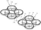
도 1은 본 발명의 일 실시예에 따라 비행 중인 드론에 무선으로 전력을 전송할 수 있는 무선충전장치의 기본적인 구성 관계를 보인다.
도 2는 본 발명의 일 실시예에 따라 상부 방향에서 바라본 무선충전장치와 드론 간의 배치 관계를 보인다.
도 3은 하부 방향에서 바라본 무선충전장치와 드론 간의 배치 관계를 보인다.
도 4는 측방에서 바라본 무선충전장치와 드론 간의 배치 관계를 보인다.
도 5는 무선 송신기와 무선 수신기 간의 작동 원리를 보인다.
도 6은 무선충전장치의 무선 송신기와 드론의 무선 수신기가 접힘 동작을 하는 구조의 일예를 보인다.
도 7은 무선충전장치의 무선 송신기와 드론의 무선 수신기가 접힘 동작을 하는 구조의 다른 예를 보인다.
도 8은 무선 송신기와 무선 수신기가 전자석이 배치된 일측면 상에 내장된 상태를 보인다.
도 9는 무선 송신기와 무선 수신기가 전자석들의 사이에 외장 상태로 배치된 모습을 보인다.
도 10은 무선충전장치를 이루는 전자석이 복수개의 열로 이루어진 상태를 보인다.1 shows a basic configuration of a wireless charging device capable of wirelessly transmitting power to a flying dron according to an embodiment of the present invention.
FIG. 2 shows a layout relationship between a wireless charging device and a dron viewed from an upper direction according to an embodiment of the present invention.
FIG. 3 shows the arrangement relationship between the wireless charging device and the drone viewed in the lower direction.
FIG. 4 shows a layout relationship between the wireless charging device and the drone viewed from the side.
Figure 5 shows the operating principle between a wireless transmitter and a wireless receiver.
FIG. 6 shows an example of a structure in which a radio transmitter of a wireless charging device and a radio receiver of a drone perform a folding operation.
7 shows another example of the structure in which the radio transmitter of the wireless charging device and the radio receiver of the drone perform a folding operation.
8 shows a state in which the radio transmitter and the radio receiver are built on one side where the electromagnets are arranged.
Figure 9 shows a radio transmitter and a radio receiver placed in an externally placed state between the electromagnets.
Fig. 10 shows a state in which the electromagnet forming the wireless charging device is composed of a plurality of rows.
이하, 첨부된 도면을 참조하여 본 발명의 실시예를 더욱 상세히 설명하기로 한다. 그러나, 본 발명은 이하에서 개시되는 실시예에 한정되는 것이 아니라 서로 다른 다양한 형태로 구현될 것이며, 단지 본 실시예들은 본 발명의 개시가 완전하도록 하며, 통상의 지식을 가진 자에게 발명의 범주를 완전하게 알려주기 위해 제공되는 것이다. 도면 상에서 동일 부호는 동일한 요소를 지칭한다.Hereinafter, embodiments of the present invention will be described in detail with reference to the accompanying drawings. It should be understood, however, that the invention is not limited to the disclosed embodiments, but is capable of other various forms of implementation, and that these embodiments are provided so that this disclosure will be thorough and complete, It is provided to let you know completely. Wherein like reference numerals refer to like elements throughout.
각 도면의 구성요소들에 참조부호를 부가함에 있어서, 동일한 구성요소들에 대해서는 비록 다른 도면상에 표시되더라도 가능한 한 동일한 부호를 가지도록 하고 있음에 유의해야 한다. 또한, 본 발명을 설명함에 있어, 관련된 공지 구성 또는 기능에 대한 구체적인 설명이 본 발명의 요지를 흐릴 수 있다고 판단되는 경우에는 그 상세한 설명은 생략한다.It should be noted that, in adding reference numerals to the constituent elements of the drawings, the same constituent elements are denoted by the same reference symbols as possible even if they are shown in different drawings. In the following description of the present invention, a detailed description of known functions and configurations incorporated herein will be omitted when it may make the subject matter of the present invention rather unclear.
이하, 도면을 참조하여 본 발명의 실시예에 따라 공중에서 비행 중인 드론에 무선으로 전력을 전송할 수 있는 무선충전장치를 설명한다.Hereinafter, a wireless charging device capable of wirelessly transmitting power to a flying drones according to an embodiment of the present invention will be described with reference to the drawings.
도 1 내지 도 4를 참조하면, 무선충전장치(100)는 공중에서 연속비행이 가능한 상태의 충전 바디(110), 충전 바디(110)의 공중 부양을 가능하게 하도록 상부 방향으로의 항력을 발생하게 하는 하나 이상의 프로펠러(120), 충전 바디(110) 상에 구비되는 하나 이상의 전자석(130), 충전 바디(110) 상에 배치되는 거리 감지부(140), 충전 바디(110) 상에 결합되는 무선 송신기(150) 및 충전 바디(110)의 중앙부에 배치된 상태에서 무선 송신기(150)와 거리 감지부(140)에 전기적으로 연결되는 제어부(160)를 포함한다.Referring to FIGS. 1 to 4, the
무선충전장치(100)는 구조와 제어 방식이 기본적으로 드론(10)과 실질적으로는 동일한 무인 비행체일 수 있지만, 호버링(hovering) 동작을 수행하여 드론(10)과의 사이에 무선 충전을 수행한다. 즉, 공중 정지 상태에서 드론(10)의 도킹을 유도하여 드론(10)과의 사이에 무선 충전을 수행한다.The
상기와 같이, 무인 비행체로서의 기능을 하는 드론(10)은 상기 무선충전장치(100)와 실질적으로 동일한 외형을 가지는 것으로 설명 가능하다.As described above, the
드론(10)은 공중에서 연속비행이 가능한 상태의 드론 바디(11), 드론 바디(11)의 공중 부양을 가능하게 하도록 상부 방향으로의 항력을 발생하게 하는 하나 이상의 드론 회전체(12), 드론 바디(11) 상에 구비되는 하나 이상의 자성체(13), 드론 바디(11) 상에 결합되는 무선 수신기(15) 및 드론 바디(11) 상에 배치되는 드론 제어기(16)를 포함한다.The
드론(10)은 무선 수신기(15)를 구비하는 한, 단일 프로펠러형 또는 4단 프로펠러형 등 기존의 어느 것을 이용해도 좋다. 드론(10)은 무선 충전 이전 정상 비행 중인 드론을 상정하기로 한다.As long as the
드론(10)은 무선충전장치(100)의 무선 송신기(150)로부터의 전력을 수신할 수 있는 무선 수신기(15)가 장착된 상태이다.The
공중에서 드론(10)이 무선충전장치(100)로 기설정된 기준 거리 내로 근접하는 경우에, 상기 전자석(130)에 전류를 공급하여 전자석에 극성을 유도함으로써 드론과 무선충전장치를 밀착하게 하고, 이를 통해 무선 송신기와 무선 충전기는 자기 공진 방식으로 전력을 송수신한다.When the
무선충전장치(100)와 드론(10)은 무선충전장치(100)를 이루는 무선 송신부(150)와 드론(10)의 무선 수신부(15) 간에 자기공명 방식을 이용한 충전 방식으로 무선 충전이 이루어진다.The
구체적으로, 도 5를 참조하면, 무선 송신부(150) 및 무선 수신부(15) 상에는 각각 송신 공진 코일 및 수신 공진 코일이 내장된 상태이고, 기설정된 기준 거리 내로 드론(10)과 무선충전장치(100)가 근접하는 경우에는, 무선 송신부(150) 내의 송신 공진 코일 상으로 배터리를 통해 RF 전력을 공급하여 자기장을 발생하게 한다. 이러한 경우에는 패러데이의 법칙에 의해 무선 수신부(15)의 코일 상에 반대 방향의 유도 자기장이 발생하고, 무선 수신부(15)에 연결된 드론(10)의 부하 측에 전력을 충전하게 한다.5, the transmission and reception resonance coils and the reception resonance coils are installed on the
상기 자기공명방식은 소리굽쇠의 진동 에너지가 주변으로 이동하는 공명현상을 이용해 전자파를 1m 이상 보내 충전하는 방식을 말한다. 이러한 방식은 한대의 무선 송신부를 이용하여 복수의 무선 수신부 상으로의 충전을 가능하게 하는 특징이 있다.The magnetic resonance method refers to a method in which electromagnetic waves are transmitted by more than 1 m by using the resonance phenomenon in which the vibration energy of the tuning fork moves around. This method is characterized in that it is possible to charge the plurality of wireless receiving units by using one wireless transmitting unit.
주파수를 이용한 충전 방식은 4.5m 거리에서도 전원 저장 장치인 배터리가 없는 웨어러블 디바이스, 스마트 기기 등 전원이 필요한 전자기기를 배터리 없이 실시간으로 동작 시킬 수 있다.The charging method using the frequency can operate the electronic devices requiring power such as wearable devices and smart devices without battery as power storage device in real time without battery even at a distance of 4.5m.
한편, 무선충전장치(100)는 다른 실시예로서, 자기유도방식을 이용한 충전 방식으로 무선 충전을 채용할 수 있다. 상기 자기유도방식은 1차 코일에 해당하는 무선 송신부(150)에서 생성된 자기장에 의하여 2차 코일에 해당하는 무선 수신부(15) 상에 유도전류가 흘러 전기 에너지를 공급하는 방식이다.On the other hand, the
상기와 같이 무선 충전 방식에는 자기 유도와 자기 공진식이 있다. 자기 유도식은 코일 간 전자기 유도 현상을 이용하며 근거리 전송이 가능하고 코일의 소형화에 유리하지만, 전송 거리가 짧고 코일간 정렬에 민감하다.As described above, the wireless charging system includes magnetic induction and self-resonance. The magnetic induction method utilizes the electromagnetic induction phenomenon between the coils and is capable of short distance transmission and is advantageous for miniaturization of the coil, but the transmission distance is short and is sensitive to alignment between coils.
한편, 자기 공진 방식은 코일 간 자기공진 현상을 이용하여 예를 들어 1m 이내의 전송도 가능하며, 코일 간 정렬 자유도가 높으므로 비행 중인 드론을 위한 충전 방식으로 적합하다. 코일 설계가 어렵고 전자파 노출이 많다는 문제가 있으나, 원격 드론 충전 방식을 택하면 후자는 문제되지 않고, 코일 설계 또한 점점 발전하는 추세에 있다. 상기의 이유로 본 발명에서는 자기 공진 방식을 택하는 것이 바람직하다.On the other hand, the self-resonance method is suitable as a charging method for a flying dragon because the self-resonance phenomenon between coils can be used to transmit within 1m, for example, and the degree of freedom in alignment between coils is high. Although coil design is difficult and electromagnetic wave exposure is problematic, the latter is not a problem if the remote drone charging method is adopted, and the coil design is also gradually developing. For the above reason, it is preferable to adopt the self-resonance method in the present invention.
무선충전장치(100)는 드론(10)을 결합할 수 있는 전자석(130)을 충전 바디(120)의 일 측면 상에 하나 이상 장착한다. 상기 전자석(130)은 평소에는 자성을 띄지 않지만, 자성체(13)가 결합된 드론(100)이 접근하는 경우에는 거리 감지 제어기(140)를 통해 적정 거리 범위인지 여부를 센싱함으로써, 드론(10)이 접근하면 전자석(130)의 자성을 발생하도록 하여 서로 접속될 수 있게 한다.The
본 발명에서의 자성체(13)는 자기장이 유도되면 자화되어 자력을 갖고, 자기장이 유도되지 않으면 자화되지 않는 자성체를 의미한다. 상기 전자석(130)에 전류를 공급함으로써 자성을 띠게 되는 경우에, 전자석(130)과 자성체(13) 간의 인력을 통해서 무선충전장치(100)와 드론(10)의 결합을 가능하게 한다. 상기 자성체(13)는 무선충전장치(100)를 이루는 전자석(130)을 통해 발생되는 자기장에 의해 유도되어 자성을 띄게 된 상태에서 전자석(130)에 부착되어진다. 한편으로는, 전자석(130)을 통한 자기장이 없어지게 되면, 상기 자성체(13)에 유도된 자성은 소멸되는 성질을 갖는다. 한편, 자성체(13) 상에는 추가적으로 전선을 권선하여 전자석으로 작동하게할 수 있다. 구체적으로는, 충전 바디(110)의 일 측면에 구비된 전자석(130)이 작동할 때, 드론(10)의 자성체(13)도 대응된 상태로 작동하게 함으로써 충전 바디(110)와 드론(10)을 밀착한 상태에서 충전이 이루어지게 한다. 이는 충전 바디(110)와 드론(10) 양측 상에 각각 구비된 전자석이 동일하게 권선된 상태에서 동일하게 전류가 흐르는 경우에는, 마주보는 전자석의 각각 다른 극이 유도되어 인력을 유발하게 된다는 것으로 설명된다.The
한편, 충전 바디(110)의 전자석(130)과 드론(10)의 자성체(13)가 다수 부착될 경우에는, 상기 전자석(130)과 자성체(13)는 순차적으로 상이한 극성으로 자화되도록 제어하는 과정을 통해 충전 바디(110)와 드론(10)의 밀착을 가능하게 한다. 상기 구조를 통해서, 전자석(130)이 다수 존재할 때, 전자석(130)과 자성체(13)가 서로 엇갈려서 붙게 되는 것을 방지함으로써 정확한 결합 위치를 유지하게 한다.When a large number of the
도 4와 같이, 무선 송신기(150)는 전자석(130)이 부착된 무선충전장치(100)의 충전 바디(120) 측면과 평행을 이루게 된다. 상기 상태에서, 드론(10)이 무선충전장치(100)에 접속되었을 때, 무선 송신기(150)는 드론(10)에 부착된 무선 수신기(15)와 마주보도록 설치되고, 무선 송신기(150)와 무선 수신기(15)의 내부에는 코일이 내장되어 있어 자기공진 방식으로 무선전력전송이 가능하다.4, the
무선충전장치(100)로 드론(10)을 충전할 때에는, 무선 송신기(150)의 송신 공진 코일과 무선 수신기(15)의 수신 공진 코일은 전력 송신 효율을 높이기 위하여 서로 마주보게 배치되도록 한다.When charging the
한편, 도 6과 같이, 무선 송신기(150)와 무선 수신기(15)는 폴딩 구조를 가진다. 무선 송신기(150)는 무선충전장치(100)의 중앙 하부 상에 배치된 상태에서 힌지 구조 등을 통해 접힘 가능한 구조를 갖는다.Meanwhile, as shown in FIG. 6, the
이를 통해서, 평소 비행 중에는 폴딩 상태를 유지하다가 드론(10)과 접속할 때만 펴져서 충전을 수행할 수 있다.In this way, it is possible to maintain the folding state during normal flight and to perform charging only when connecting with the
무선 송신기(150)는 충전 바디(110)의 중심에 위치하여 무선충전장치(100)의 중심을 유지하거나, 또는 전자석(130)을 중심으로 하여 상하 양측 방향으로 상기 충전 바디(110) 상에 부착되어 무선전력전송의 효율을 기할 수 있다.The
전자석(130)은 예시적으로 무선충전장치(100)의 일 측면에 복수개가 일렬로 부착 가능하다. 상기 전자석(130)은 순차적으로 극을 다르게 변동하게 해서 접근하는 드론(10)이 무선충전장치(100)의 특정한 영역에 정확히 부착 가능하도록 유도할 수 있다.A plurality of
도 7을 참조하여, 무선 송신기(150)와 무선 수신기(15)의 폴딩 구조의 다른 예를 보인다. 무선 송신기(150)와 무선 수신기(15)는 펼쳐진 상태에서는 각각 전자석(130)과 자성체(13)의 하부에 배치된다. 이후 접힌 상태에서는 각각 충전 바디(110)와 드론(10)의 중앙 하부에 위치한다.도 8을 참조하면, 무선 송신기(150)는 충전 바디(120) 일측면 상에 내장된 상태로 전자석(130)의 사이에 배치된다. 즉, 무선 송신기(150)는 무선충전장치(100)의 외측으로는 노출되지 않은 상태에서 충전 바디(120)의 일측을 통하여 무선전력전송을 가능하게 한 상태로 유지된다. 무선 수신기(15)의 경우에도 드론 바디(11)의 일측면 상에 내장된 상태로 자성체(13)의 사이에 배치된다.7, another example of the folding structure of the
한편, 도 9를 참조하면, 무선 송신기(150)는 충전 바디(120)의 일측면 상에 외장된 상태로 전자석(130)의 사이에 배치된다. 즉, 무선 송신기(150)는 무선충전장치(100)의 외측으로 노출된 상태에서 충전 바디(120)의 일측을 통한 무선전력전송을 가능하게 한다. 다른 실시예로서, 무선 송신기(150)는 전자석(130)의 사이에서 충전 바디(120)의 하부 방향으로 배치될 수 있다.9, the
도 10을 참조하면, 전자석(130)은 충전 바디(120)의 일측면 상에 복수개의 열을 이루어 배치된다. 구체적으로는, 상부에서 하부 방향으로 2개 또는 3개 층으로 간섭되지 않는 상태를 이루도록 배치된다. 즉, 상기와 같이 무선충전장치(100)의 측면 상에 상하를 따라 복수개의 열로 이루어진 전자석들은 상기 무선충전장치(100)가 위아래로 꺽여 변형되지 않도록 안정적으로 고정된 상태를 유지한다. Referring to FIG. 10, the
상술한 바와 같이 본 발명은 프로펠러를 통해 공중에서 연속비행이 가능한 상태의 충전 바디 상에 구비된 전자석 및 무선 송신기를 갖는 무선충전장치를 제공하고, 충전을 요하는 드론이 상기 무선충전장치에 근접하는 경우에 상기 전자석을 통해 상기 드론과 무선충전장치 간의 결합을 유도하고, 상기 무선 송신기와 무선 충전기는 자기 공진 방식으로 전력을 송수신하게 한다.As described above, the present invention provides a wireless charging apparatus having an electromagnet and a radio transmitter provided on a charging body capable of continuous flight in the air through a propeller, and a dron requiring charging is located close to the wireless charging apparatus The coupling between the drones and the wireless charging device is induced through the electromagnet, and the wireless transmitter and the wireless charging device transmit and receive power in a self-resonating manner.
이상의 설명은 본 발명의 기술 사상을 예시적으로 설명한 것에 불과한 것으로서, 본 발명이 속하는 기술 분야에서 통상의 지식을 가진 자라면 본 발명의 본질적인 특성에서 벗어나지 않는 범위에서 다양한 수정 및 변형이 가능할 것이다. 따라서, 본 발명에 개시된 실시예들은 본 발명의 기술 사상을 한정하기 위한 것이 아니라 설명하기 위한 것이고, 이러한 실시예에 의하여 본 발명의 기술 사상의 범위가 한정되는 것은 아니다. 본 발명의 보호 범위는 아래의 청구범위에 의하여 해석되어야 하며, 그와 동등한 범위 내에 있는 모든 기술 사상은 본 발명의 권리범위에 포함되는 것으로 해석되어야 할 것이다.The foregoing description is merely illustrative of the technical idea of the present invention, and various changes and modifications may be made by those skilled in the art without departing from the essential characteristics of the present invention. Therefore, the embodiments disclosed in the present invention are intended to illustrate rather than limit the scope of the present invention, and the scope of the technical idea of the present invention is not limited by these embodiments. The scope of protection of the present invention should be construed according to the following claims, and all technical ideas within the scope of equivalents should be construed as falling within the scope of the present invention.
10 : 드론
11 : 드론 바디
12 : 드론 회전체
13 : 자성체
15 : 무선 수신기
16 : 드론 제어기
100 : 무선충전장치
110 : 충전 바디
120 : 프로펠러
130 : 전자석
140 : 거리 감지부
150 : 무선 송신기
160 : 제어부10: Drones
11: Drone body
12: Drone rotating body
13: magnetic body
15: Wireless receiver
16: Drone controller
100: Wireless charging device
110: Charging body
120: Propeller
130: electromagnet
140:
150: wireless transmitter
160:
Claims (6)
Translated fromKorean상기 무선충전장치의 본체를 이루는 충전 바디;
상기 충전 바디 상에 배치된 상태에서 연속비행을 가능하게 하는 프로펠러;
상기 충전 바디의 중앙 하부에 일측 단부가 결합된 일직선 형태의 제1 고정로드와 상기 제1 고정로드의 타측 단부에 일측 단부가 회전 가능하게 연결된 일직선 형태의 제2 회전 로드로 이루어진 제1 위치변경부;
상기 제2 회전 로드의 타측 단부에 결합된 무선 송신기; 및
상기 충전 바디의 일 측면 상에 상부에서 하부 방향으로 복수개의 층으로 간섭되지 않는 상태를 이루도록 배치되어 구비되는 적어도 하나의 전자석;을 포함하고,
상기 전자석과 동일한 배치 구조로 적어도 하나 이상의 자성체를 그 일 측면 상에 구비한 드론이 상기 무선충전장치에 기준 거리 내로 접근하면, 상기 무선충전장치의 전자석이 작동하여 상기 충전 바디의 측면과 상기 드론의 측면이 밀착하게 되고, 상기 밀착한 측면을 기준으로 상기 제1 위치변경부 및 무선 송신기와 대칭되도록 상기 드론에 제2 위치변경부 및 무선 수신기가 구비되어져, 일반 비행 시에는 상기 제1,2 위치변경부가 각각 접혀서 상기 무선 송신기는 상기 충전 바디의 중앙 하부에 위치하며 상기 무선 수신기는 상기 드론의 중앙 하부에 위치하게 되고, 상기 충전 바디와 상기 드론이 밀착하게 되면 상기 제1,2 위치변경부가 각각 펼쳐져서 상기 무선 송신기는 상기 전자석의 하부에 위치하고 상기 무선 수신기는 상기 자성체의 하부에 위치하여 상기 무선 송신기와 상기 무선 수신기가 밀접하게 마주보게 되어지고, 상기 무선 송신기의 송신 공진 코일에서 상기무선 수신기의 수신 공진 코일로 전력을 전송하여 상기 드론을 충전시키는,
비행중 드론의 무선충전장치.
In a wireless charging device for a flying drones,
A charging body constituting the main body of the wireless charging device;
A propeller for allowing continuous flight in a deployed state on the charging body;
A first fixed rod having a straight shape coupled to one end of the center of the charged body and a second rotary rod having a straight end connected to the other end of the first fixed rod, ;
A wireless transmitter coupled to the other end of the second rotating rod; And
And at least one electromagnet disposed on one side of the charging body so as not to interfere with the plurality of layers from the top to the bottom,
When a dron having at least one magnetic body on one side thereof with the same arrangement structure as that of the electromagnet approaches to the wireless charging device within a reference distance, an electromagnet of the wireless charging device operates so that the side surface of the charging body, And a second position changing unit and a wireless receiver are provided on the drones so as to be symmetrical with respect to the first position changing unit and the wireless transmitter with respect to the close side surface, Wherein the radio transmitter is located at a lower center of the charging body and the radio receiver is positioned at a lower center of the dron. When the charging body and the dron come in close contact with each other, The radio transmitter is positioned below the electromagnet and the radio receiver is positioned above the magnetic body By getting the wireless transmitter and the wireless receiver to see closely facing, in the transmission resonant coil of the wireless transmitter to charge the drone by transmitting power to the receiving resonance coil of the radio receiver,
Wireless charging device for drones during flight.
상기 드론을 충전할 때, 상기 무선 송신기의 송신 공진 코일과 상기 무선 수신기의 수신 공진 코일은 서로 마주보게 배치되도록 하는,
비행중 드론의 무선충전장치.
The method according to claim 1,
Wherein the transmission resonance coil of the radio transmitter and the reception resonance coil of the radio receiver are arranged to face each other when the drones are charged,
Wireless charging device for drones during flight.
상기 드론의 자성체에 추가적으로 전선을 권선하여 전자석으로 작동하게 하고, 상기 충전 바디의 일 측면에 구비된 전자석이 작동할 때, 상기 드론의 자성체도 대응되게 작동하여, 상기 충전 바디와 상기 드론이 밀착되도록 하는,
비행중 드론의 무선충전장치.
The method according to claim 1,
When the electromagnet provided on one side of the charging body operates, the magnetic body of the charging / discharging body also operates correspondingly, so that the charging body and the dron are brought into close contact with each other. doing,
Wireless charging device for drones during flight.
상기 충전 바디의 전자석과 상기 드론의 자성체가 다수 부착될 경우, 상기 전자석과 상기 자성체는 순차적으로 다른 극성으로 자화되도록 제어하면서, 상기 충전 바디와 상기 드론이 밀착되도록 하는,
비행중 드론의 무선충전장치.
The method of claim 3,
Wherein when the electromagnet of the charging body and the magnetic body of the dron are attached in large numbers, the electromagnet and the magnetic body are sequentially controlled to have different polarities,
Wireless charging device for drones during flight.
상기 무선 송신기는 상기 무선충전장치의 중앙에 배치된 상태에서 폴딩 구조를 가지며, 상기 드론과 접속하는 경우에만 펼쳐져서 충전을 수행하는,
비행중 드론의 무선충전장치.
The method according to claim 1,
Wherein the wireless transmitter has a folding structure in a state of being disposed at the center of the wireless charging device and unfolds only when connected to the drones,
Wireless charging device for drones during flight.
상기 전자석은 상기 무선충전장치의 일측면 상에 복수의 열을 갖도록 배치된,
비행중 드론의 무선충전장치.The method according to claim 1,
Wherein the electromagnet is arranged to have a plurality of rows on one side of the wireless charging device,
Wireless charging device for drones during flight.
Priority Applications (1)
| Application Number | Priority Date | Filing Date | Title |
|---|---|---|---|
| KR1020180001601AKR101867424B1 (en) | 2018-01-05 | 2018-01-05 | Wireless power charging apparatus transmitting power wirelessly for drones airborne |
Applications Claiming Priority (1)
| Application Number | Priority Date | Filing Date | Title |
|---|---|---|---|
| KR1020180001601AKR101867424B1 (en) | 2018-01-05 | 2018-01-05 | Wireless power charging apparatus transmitting power wirelessly for drones airborne |
Publications (1)
| Publication Number | Publication Date |
|---|---|
| KR101867424B1true KR101867424B1 (en) | 2018-06-14 |
Family
ID=62629358
Family Applications (1)
| Application Number | Title | Priority Date | Filing Date |
|---|---|---|---|
| KR1020180001601AExpired - Fee RelatedKR101867424B1 (en) | 2018-01-05 | 2018-01-05 | Wireless power charging apparatus transmitting power wirelessly for drones airborne |
Country Status (1)
| Country | Link |
|---|---|
| KR (1) | KR101867424B1 (en) |
Cited By (6)
| Publication number | Priority date | Publication date | Assignee | Title |
|---|---|---|---|---|
| KR101973148B1 (en)* | 2018-10-31 | 2019-08-26 | 한화시스템 주식회사 | Method and apparatus for drone battery charging |
| CN114228521A (en)* | 2021-12-20 | 2022-03-25 | 歌尔科技有限公司 | Unmanned aerial vehicle equipment and wireless charging device thereof |
| WO2023047177A1 (en)* | 2021-09-21 | 2023-03-30 | Dubai Electricity & Water Authority | Uav charging system |
| CN117068420A (en)* | 2023-10-19 | 2023-11-17 | 山东省地质科学研究院 | Unmanned aerial vehicle-based self-recovery type remote sensing mapping equipment |
| WO2024181724A1 (en)* | 2023-02-28 | 2024-09-06 | 삼성전자 주식회사 | Electronic device including wireless charging device |
| CN119975894A (en)* | 2025-03-21 | 2025-05-13 | 中南大学 | Unmanned aerial vehicle collaborative wireless charging system, method, terminal device and storage medium |
Citations (3)
| Publication number | Priority date | Publication date | Assignee | Title |
|---|---|---|---|---|
| WO2015200436A1 (en)* | 2014-06-24 | 2015-12-30 | Board Of Trustees Of The University Of Alabama | Wireless power transfer systems and methods |
| WO2016134193A1 (en)* | 2015-02-19 | 2016-08-25 | Amazon Technologies, Inc. | Collective unmanned aerial vehicle configurations |
| EP3243749A1 (en)* | 2016-05-06 | 2017-11-15 | Skyx Limited | Unmanned aerial vehicle (uav) having vertical takeoff and landing (vtol) capability |
- 2018
- 2018-01-05KRKR1020180001601Apatent/KR101867424B1/ennot_activeExpired - Fee Related
Patent Citations (3)
| Publication number | Priority date | Publication date | Assignee | Title |
|---|---|---|---|---|
| WO2015200436A1 (en)* | 2014-06-24 | 2015-12-30 | Board Of Trustees Of The University Of Alabama | Wireless power transfer systems and methods |
| WO2016134193A1 (en)* | 2015-02-19 | 2016-08-25 | Amazon Technologies, Inc. | Collective unmanned aerial vehicle configurations |
| EP3243749A1 (en)* | 2016-05-06 | 2017-11-15 | Skyx Limited | Unmanned aerial vehicle (uav) having vertical takeoff and landing (vtol) capability |
Cited By (8)
| Publication number | Priority date | Publication date | Assignee | Title |
|---|---|---|---|---|
| KR101973148B1 (en)* | 2018-10-31 | 2019-08-26 | 한화시스템 주식회사 | Method and apparatus for drone battery charging |
| WO2023047177A1 (en)* | 2021-09-21 | 2023-03-30 | Dubai Electricity & Water Authority | Uav charging system |
| CN114228521A (en)* | 2021-12-20 | 2022-03-25 | 歌尔科技有限公司 | Unmanned aerial vehicle equipment and wireless charging device thereof |
| CN114228521B (en)* | 2021-12-20 | 2024-03-12 | 歌尔科技有限公司 | Unmanned aerial vehicle equipment and wireless charging device thereof |
| WO2024181724A1 (en)* | 2023-02-28 | 2024-09-06 | 삼성전자 주식회사 | Electronic device including wireless charging device |
| CN117068420A (en)* | 2023-10-19 | 2023-11-17 | 山东省地质科学研究院 | Unmanned aerial vehicle-based self-recovery type remote sensing mapping equipment |
| CN117068420B (en)* | 2023-10-19 | 2024-01-23 | 山东省地质科学研究院 | Unmanned aerial vehicle-based self-recovery type remote sensing mapping equipment |
| CN119975894A (en)* | 2025-03-21 | 2025-05-13 | 中南大学 | Unmanned aerial vehicle collaborative wireless charging system, method, terminal device and storage medium |
Similar Documents
| Publication | Publication Date | Title |
|---|---|---|
| KR101867424B1 (en) | Wireless power charging apparatus transmitting power wirelessly for drones airborne | |
| CN112567171B (en) | Unmanned aerial vehicle station | |
| US9896203B1 (en) | Unmanned aerial vehicles, charging systems for the same and methods of charging the same | |
| US10410788B1 (en) | Wireless power and data transfer for unmanned vehicles | |
| US10099561B1 (en) | Airborne unmanned aerial vehicle charging | |
| US20200039373A1 (en) | Systems and methods for charging an unmanned aerial vehicle with a host vehicle | |
| CN105162219B (en) | The charging method and charging management method of unmanned plane | |
| EP2644438B1 (en) | Vehicle base station | |
| US8862288B2 (en) | Vehicle base station | |
| US9828093B2 (en) | System for recharging remotely controlled aerial vehicle, charging station and rechargeable remotely controlled aerial vehicle, and method of use thereof | |
| US20190025830A1 (en) | Wireless charging and protection for unmanned delivery aerial vehicles | |
| US20220134899A1 (en) | Docking port and battery charging depot for an unmanned aerial vehicle and a method for docking and charging the vehicle | |
| KR101840473B1 (en) | Method for controlling formation flight | |
| CN106655322B (en) | Service-type unmanned aerial vehicle, unmanned aerial vehicle charging system and charging method | |
| CN104503349A (en) | Monitoring device based on unmanned aerial vehicle | |
| US20190237999A1 (en) | Wireless Power Transfer for Recharging Aircraft Batteries | |
| CN114365002A (en) | Radar-enabled multi-vehicle system | |
| US11919635B2 (en) | Unmanned aerial vehicles energized by power lines | |
| KR20170036297A (en) | Unmanned Aerial Vehicle, Base Station, Unmanned Aerial System and Control Method thereof | |
| KR101657669B1 (en) | Delivery device, charging system and method of operating charging system | |
| KR101670476B1 (en) | Delivery device, charging system and method of operating charging system | |
| RU168376U1 (en) | SMALL UNMANNED AIRCRAFT | |
| KR101986500B1 (en) | Expanded unmanned air vehicle assembly | |
| KR102122396B1 (en) | Combining form type wireless power transmission system for unmanned aerial vehicle | |
| KR102172209B1 (en) | Drone Reconnaissance System For Long-Distance Ocean |
Legal Events
| Date | Code | Title | Description |
|---|---|---|---|
| PA0109 | Patent application | St.27 status event code:A-0-1-A10-A12-nap-PA0109 | |
| PA0201 | Request for examination | St.27 status event code:A-1-2-D10-D11-exm-PA0201 | |
| PA0302 | Request for accelerated examination | St.27 status event code:A-1-2-D10-D17-exm-PA0302 St.27 status event code:A-1-2-D10-D16-exm-PA0302 | |
| P11-X000 | Amendment of application requested | St.27 status event code:A-2-2-P10-P11-nap-X000 | |
| P13-X000 | Application amended | St.27 status event code:A-2-2-P10-P13-nap-X000 | |
| P11-X000 | Amendment of application requested | St.27 status event code:A-2-2-P10-P11-nap-X000 | |
| P13-X000 | Application amended | St.27 status event code:A-2-2-P10-P13-nap-X000 | |
| PE0902 | Notice of grounds for rejection | St.27 status event code:A-1-2-D10-D21-exm-PE0902 | |
| P11-X000 | Amendment of application requested | St.27 status event code:A-2-2-P10-P11-nap-X000 | |
| P13-X000 | Application amended | St.27 status event code:A-2-2-P10-P13-nap-X000 | |
| R18-X000 | Changes to party contact information recorded | St.27 status event code:A-3-3-R10-R18-oth-X000 | |
| R18-X000 | Changes to party contact information recorded | St.27 status event code:A-3-3-R10-R18-oth-X000 | |
| E701 | Decision to grant or registration of patent right | ||
| PE0701 | Decision of registration | St.27 status event code:A-1-2-D10-D22-exm-PE0701 | |
| GRNT | Written decision to grant | ||
| PR0701 | Registration of establishment | St.27 status event code:A-2-4-F10-F11-exm-PR0701 | |
| PR1002 | Payment of registration fee | St.27 status event code:A-2-2-U10-U11-oth-PR1002 Fee payment year number:1 | |
| PG1601 | Publication of registration | St.27 status event code:A-4-4-Q10-Q13-nap-PG1601 | |
| R18-X000 | Changes to party contact information recorded | St.27 status event code:A-5-5-R10-R18-oth-X000 | |
| PN2301 | Change of applicant | St.27 status event code:A-5-5-R10-R11-asn-PN2301 | |
| PN2301 | Change of applicant | St.27 status event code:A-5-5-R10-R14-asn-PN2301 | |
| PR1001 | Payment of annual fee | St.27 status event code:A-4-4-U10-U11-oth-PR1001 Fee payment year number:4 | |
| PN2301 | Change of applicant | St.27 status event code:A-5-5-R10-R11-asn-PN2301 | |
| PN2301 | Change of applicant | St.27 status event code:A-5-5-R10-R14-asn-PN2301 | |
| P14-X000 | Amendment of ip right document requested | St.27 status event code:A-5-5-P10-P14-nap-X000 | |
| P16-X000 | Ip right document amended | St.27 status event code:A-5-5-P10-P16-nap-X000 | |
| Q16-X000 | A copy of ip right certificate issued | St.27 status event code:A-4-4-Q10-Q16-nap-X000 | |
| PR1001 | Payment of annual fee | St.27 status event code:A-4-4-U10-U11-oth-PR1001 Fee payment year number:5 | |
| P22-X000 | Classification modified | St.27 status event code:A-4-4-P10-P22-nap-X000 | |
| PC1903 | Unpaid annual fee | St.27 status event code:A-4-4-U10-U13-oth-PC1903 Not in force date:20230608 Payment event data comment text:Termination Category : DEFAULT_OF_REGISTRATION_FEE | |
| PC1903 | Unpaid annual fee | St.27 status event code:N-4-6-H10-H13-oth-PC1903 Ip right cessation event data comment text:Termination Category : DEFAULT_OF_REGISTRATION_FEE Not in force date:20230608 | |
| P22-X000 | Classification modified | St.27 status event code:A-4-4-P10-P22-nap-X000 |