KR101867261B1 - A compressor swash plate and a compressor equipped with the swash plate - Google Patents
A compressor swash plate and a compressor equipped with the swash plateDownload PDFInfo
- Publication number
- KR101867261B1 KR101867261B1KR1020187008595AKR20187008595AKR101867261B1KR 101867261 B1KR101867261 B1KR 101867261B1KR 1020187008595 AKR1020187008595 AKR 1020187008595AKR 20187008595 AKR20187008595 AKR 20187008595AKR 101867261 B1KR101867261 B1KR 101867261B1
- Authority
- KR
- South Korea
- Prior art keywords
- swash plate
- coating layer
- compressor
- convex portion
- flat
- Prior art date
- Legal status (The legal status is an assumption and is not a legal conclusion. Google has not performed a legal analysis and makes no representation as to the accuracy of the status listed.)
- Active
Links
- 239000011247coating layerSubstances0.000claimsabstractdescription74
- 239000000758substrateSubstances0.000claimsabstractdescription8
- 230000014509gene expressionEffects0.000claimsdescription6
- 238000000034methodMethods0.000claimsdescription5
- 238000003825pressingMethods0.000claimsdescription4
- 239000000463materialSubstances0.000description19
- 229920005989resinPolymers0.000description10
- 239000011347resinSubstances0.000description10
- 238000005520cutting processMethods0.000description7
- 239000010687lubricating oilSubstances0.000description6
- 239000002245particleSubstances0.000description5
- 239000007787solidSubstances0.000description5
- XEEYBQQBJWHFJM-UHFFFAOYSA-NIronChemical compound[Fe]XEEYBQQBJWHFJM-UHFFFAOYSA-N0.000description4
- 239000011230binding agentSubstances0.000description4
- 230000005489elastic deformationEffects0.000description4
- 230000001050lubricating effectEffects0.000description4
- 239000003921oilSubstances0.000description4
- 239000000314lubricantSubstances0.000description3
- RYGMFSIKBFXOCR-UHFFFAOYSA-NCopperChemical compound[Cu]RYGMFSIKBFXOCR-UHFFFAOYSA-N0.000description2
- 239000004696Poly ether ether ketoneSubstances0.000description2
- 239000004693PolybenzimidazoleSubstances0.000description2
- 229910052581Si3N4Inorganic materials0.000description2
- VYPSYNLAJGMNEJ-UHFFFAOYSA-NSilicium dioxideChemical compoundO=[Si]=OVYPSYNLAJGMNEJ-UHFFFAOYSA-N0.000description2
- 239000005083Zinc sulfideSubstances0.000description2
- 238000005299abrasionMethods0.000description2
- XAGFODPZIPBFFR-UHFFFAOYSA-NaluminiumChemical compound[Al]XAGFODPZIPBFFR-UHFFFAOYSA-N0.000description2
- 229910052782aluminiumInorganic materials0.000description2
- 229910052802copperInorganic materials0.000description2
- 239000010949copperSubstances0.000description2
- 230000000694effectsEffects0.000description2
- 229910052742ironInorganic materials0.000description2
- 238000005461lubricationMethods0.000description2
- 238000002156mixingMethods0.000description2
- CWQXQMHSOZUFJS-UHFFFAOYSA-Nmolybdenum disulfideChemical compoundS=[Mo]=SCWQXQMHSOZUFJS-UHFFFAOYSA-N0.000description2
- 229910052982molybdenum disulfideInorganic materials0.000description2
- 229920002312polyamide-imidePolymers0.000description2
- 229920002480polybenzimidazolePolymers0.000description2
- 229920002530polyetherether ketonePolymers0.000description2
- 229920001721polyimidePolymers0.000description2
- 239000009719polyimide resinSubstances0.000description2
- 229920001343polytetrafluoroethylenePolymers0.000description2
- 239000004810polytetrafluoroethyleneSubstances0.000description2
- HQVNEWCFYHHQES-UHFFFAOYSA-Nsilicon nitrideChemical compoundN12[Si]34N5[Si]62N3[Si]51N64HQVNEWCFYHHQES-UHFFFAOYSA-N0.000description2
- 229920005992thermoplastic resinPolymers0.000description2
- 229920001187thermosetting polymerPolymers0.000description2
- 229910052984zinc sulfideInorganic materials0.000description2
- 229910052582BNInorganic materials0.000description1
- PZNSFCLAULLKQX-UHFFFAOYSA-NBoron nitrideChemical compoundN#BPZNSFCLAULLKQX-UHFFFAOYSA-N0.000description1
- OKTJSMMVPCPJKN-UHFFFAOYSA-NCarbonChemical class[C]OKTJSMMVPCPJKN-UHFFFAOYSA-N0.000description1
- YCKRFDGAMUMZLT-UHFFFAOYSA-NFluorine atomChemical compound[F]YCKRFDGAMUMZLT-UHFFFAOYSA-N0.000description1
- 239000004677NylonSubstances0.000description1
- 239000004952PolyamideSubstances0.000description1
- 239000004962Polyamide-imideSubstances0.000description1
- PNEYBMLMFCGWSK-UHFFFAOYSA-Naluminium oxideInorganic materials[O-2].[O-2].[O-2].[Al+3].[Al+3]PNEYBMLMFCGWSK-UHFFFAOYSA-N0.000description1
- 238000005452bendingMethods0.000description1
- 239000011248coating agentSubstances0.000description1
- 238000000576coating methodMethods0.000description1
- 229920001971elastomerPolymers0.000description1
- 239000000806elastomerSubstances0.000description1
- 239000003822epoxy resinSubstances0.000description1
- 230000002349favourable effectEffects0.000description1
- 239000012530fluidSubstances0.000description1
- 239000011737fluorineSubstances0.000description1
- 229910052731fluorineInorganic materials0.000description1
- 238000005242forgingMethods0.000description1
- 230000005484gravityEffects0.000description1
- 230000020169heat generationEffects0.000description1
- 238000003754machiningMethods0.000description1
- 150000001247metal acetylidesChemical class0.000description1
- 238000012986modificationMethods0.000description1
- 230000004048modificationEffects0.000description1
- 150000004767nitridesChemical class0.000description1
- 229920001778nylonPolymers0.000description1
- 239000005011phenolic resinSubstances0.000description1
- 229920002647polyamidePolymers0.000description1
- 229920000647polyepoxidePolymers0.000description1
- -1polytetrafluoroethylenePolymers0.000description1
- 230000000717retained effectEffects0.000description1
- 238000005096rolling processMethods0.000description1
- HBMJWWWQQXIZIP-UHFFFAOYSA-Nsilicon carbideChemical compound[Si+]#[C-]HBMJWWWQQXIZIP-UHFFFAOYSA-N0.000description1
- 239000000377silicon dioxideSubstances0.000description1
- 150000004763sulfidesChemical class0.000description1
- 239000012780transparent materialSubstances0.000description1
- ITRNXVSDJBHYNJ-UHFFFAOYSA-Ntungsten disulfideChemical compoundS=[W]=SITRNXVSDJBHYNJ-UHFFFAOYSA-N0.000description1
- 230000000007visual effectEffects0.000description1
- DRDVZXDWVBGGMH-UHFFFAOYSA-Nzinc;sulfideChemical compound[S-2].[Zn+2]DRDVZXDWVBGGMH-UHFFFAOYSA-N0.000description1
Images


Classifications
- F—MECHANICAL ENGINEERING; LIGHTING; HEATING; WEAPONS; BLASTING
- F04—POSITIVE - DISPLACEMENT MACHINES FOR LIQUIDS; PUMPS FOR LIQUIDS OR ELASTIC FLUIDS
- F04B—POSITIVE-DISPLACEMENT MACHINES FOR LIQUIDS; PUMPS
- F04B27/00—Multi-cylinder pumps specially adapted for elastic fluids and characterised by number or arrangement of cylinders
- F04B27/08—Multi-cylinder pumps specially adapted for elastic fluids and characterised by number or arrangement of cylinders having cylinders coaxial with, or parallel or inclined to, main shaft axis
- F04B27/10—Multi-cylinder pumps specially adapted for elastic fluids and characterised by number or arrangement of cylinders having cylinders coaxial with, or parallel or inclined to, main shaft axis having stationary cylinders
- F04B27/12—Multi-cylinder pumps specially adapted for elastic fluids and characterised by number or arrangement of cylinders having cylinders coaxial with, or parallel or inclined to, main shaft axis having stationary cylinders having plural sets of cylinders or pistons
- F—MECHANICAL ENGINEERING; LIGHTING; HEATING; WEAPONS; BLASTING
- F04—POSITIVE - DISPLACEMENT MACHINES FOR LIQUIDS; PUMPS FOR LIQUIDS OR ELASTIC FLUIDS
- F04B—POSITIVE-DISPLACEMENT MACHINES FOR LIQUIDS; PUMPS
- F04B27/00—Multi-cylinder pumps specially adapted for elastic fluids and characterised by number or arrangement of cylinders
- F04B27/08—Multi-cylinder pumps specially adapted for elastic fluids and characterised by number or arrangement of cylinders having cylinders coaxial with, or parallel or inclined to, main shaft axis
- F04B27/10—Multi-cylinder pumps specially adapted for elastic fluids and characterised by number or arrangement of cylinders having cylinders coaxial with, or parallel or inclined to, main shaft axis having stationary cylinders
- F04B27/1036—Component parts, details, e.g. sealings, lubrication
- F—MECHANICAL ENGINEERING; LIGHTING; HEATING; WEAPONS; BLASTING
- F16—ENGINEERING ELEMENTS AND UNITS; GENERAL MEASURES FOR PRODUCING AND MAINTAINING EFFECTIVE FUNCTIONING OF MACHINES OR INSTALLATIONS; THERMAL INSULATION IN GENERAL
- F16C—SHAFTS; FLEXIBLE SHAFTS; ELEMENTS OR CRANKSHAFT MECHANISMS; ROTARY BODIES OTHER THAN GEARING ELEMENTS; BEARINGS
- F16C17/00—Sliding-contact bearings for exclusively rotary movement
- F16C17/10—Sliding-contact bearings for exclusively rotary movement for both radial and axial load
- F—MECHANICAL ENGINEERING; LIGHTING; HEATING; WEAPONS; BLASTING
- F16—ENGINEERING ELEMENTS AND UNITS; GENERAL MEASURES FOR PRODUCING AND MAINTAINING EFFECTIVE FUNCTIONING OF MACHINES OR INSTALLATIONS; THERMAL INSULATION IN GENERAL
- F16C—SHAFTS; FLEXIBLE SHAFTS; ELEMENTS OR CRANKSHAFT MECHANISMS; ROTARY BODIES OTHER THAN GEARING ELEMENTS; BEARINGS
- F16C29/00—Bearings for parts moving only linearly
- F16C29/02—Sliding-contact bearings
- F—MECHANICAL ENGINEERING; LIGHTING; HEATING; WEAPONS; BLASTING
- F16—ENGINEERING ELEMENTS AND UNITS; GENERAL MEASURES FOR PRODUCING AND MAINTAINING EFFECTIVE FUNCTIONING OF MACHINES OR INSTALLATIONS; THERMAL INSULATION IN GENERAL
- F16C—SHAFTS; FLEXIBLE SHAFTS; ELEMENTS OR CRANKSHAFT MECHANISMS; ROTARY BODIES OTHER THAN GEARING ELEMENTS; BEARINGS
- F16C33/00—Parts of bearings; Special methods for making bearings or parts thereof
- F16C33/02—Parts of sliding-contact bearings
- F16C33/04—Brasses; Bushes; Linings
- F16C33/06—Sliding surface mainly made of metal
- F16C33/10—Construction relative to lubrication
- F16C33/1025—Construction relative to lubrication with liquid, e.g. oil, as lubricant
- F16C33/106—Details of distribution or circulation inside the bearings, e.g. details of the bearing surfaces to affect flow or pressure of the liquid
- F16C33/1065—Grooves on a bearing surface for distributing or collecting the liquid
- F—MECHANICAL ENGINEERING; LIGHTING; HEATING; WEAPONS; BLASTING
- F16—ENGINEERING ELEMENTS AND UNITS; GENERAL MEASURES FOR PRODUCING AND MAINTAINING EFFECTIVE FUNCTIONING OF MACHINES OR INSTALLATIONS; THERMAL INSULATION IN GENERAL
- F16C—SHAFTS; FLEXIBLE SHAFTS; ELEMENTS OR CRANKSHAFT MECHANISMS; ROTARY BODIES OTHER THAN GEARING ELEMENTS; BEARINGS
- F16C33/00—Parts of bearings; Special methods for making bearings or parts thereof
- F16C33/02—Parts of sliding-contact bearings
- F16C33/04—Brasses; Bushes; Linings
- F16C33/06—Sliding surface mainly made of metal
- F16C33/12—Structural composition; Use of special materials or surface treatments, e.g. for rust-proofing
- F—MECHANICAL ENGINEERING; LIGHTING; HEATING; WEAPONS; BLASTING
- F16—ENGINEERING ELEMENTS AND UNITS; GENERAL MEASURES FOR PRODUCING AND MAINTAINING EFFECTIVE FUNCTIONING OF MACHINES OR INSTALLATIONS; THERMAL INSULATION IN GENERAL
- F16C—SHAFTS; FLEXIBLE SHAFTS; ELEMENTS OR CRANKSHAFT MECHANISMS; ROTARY BODIES OTHER THAN GEARING ELEMENTS; BEARINGS
- F16C33/00—Parts of bearings; Special methods for making bearings or parts thereof
- F16C33/02—Parts of sliding-contact bearings
- F16C33/04—Brasses; Bushes; Linings
- F16C33/20—Sliding surface consisting mainly of plastics
- F16C33/203—Multilayer structures, e.g. sleeves comprising a plastic lining
- F16C33/205—Multilayer structures, e.g. sleeves comprising a plastic lining with two layers
- F—MECHANICAL ENGINEERING; LIGHTING; HEATING; WEAPONS; BLASTING
- F16—ENGINEERING ELEMENTS AND UNITS; GENERAL MEASURES FOR PRODUCING AND MAINTAINING EFFECTIVE FUNCTIONING OF MACHINES OR INSTALLATIONS; THERMAL INSULATION IN GENERAL
- F16C—SHAFTS; FLEXIBLE SHAFTS; ELEMENTS OR CRANKSHAFT MECHANISMS; ROTARY BODIES OTHER THAN GEARING ELEMENTS; BEARINGS
- F16C33/00—Parts of bearings; Special methods for making bearings or parts thereof
- F16C33/30—Parts of ball or roller bearings
- F16C33/66—Special parts or details in view of lubrication
- F16C33/6696—Special parts or details in view of lubrication with solids as lubricant, e.g. dry coatings, powder
- F—MECHANICAL ENGINEERING; LIGHTING; HEATING; WEAPONS; BLASTING
- F05—INDEXING SCHEMES RELATING TO ENGINES OR PUMPS IN VARIOUS SUBCLASSES OF CLASSES F01-F04
- F05C—INDEXING SCHEME RELATING TO MATERIALS, MATERIAL PROPERTIES OR MATERIAL CHARACTERISTICS FOR MACHINES, ENGINES OR PUMPS OTHER THAN NON-POSITIVE-DISPLACEMENT MACHINES OR ENGINES
- F05C2251/00—Material properties
- F05C2251/14—Self lubricating materials; Solid lubricants
- F—MECHANICAL ENGINEERING; LIGHTING; HEATING; WEAPONS; BLASTING
- F05—INDEXING SCHEMES RELATING TO ENGINES OR PUMPS IN VARIOUS SUBCLASSES OF CLASSES F01-F04
- F05C—INDEXING SCHEME RELATING TO MATERIALS, MATERIAL PROPERTIES OR MATERIAL CHARACTERISTICS FOR MACHINES, ENGINES OR PUMPS OTHER THAN NON-POSITIVE-DISPLACEMENT MACHINES OR ENGINES
- F05C2253/00—Other material characteristics; Treatment of material
- F05C2253/12—Coating
- F—MECHANICAL ENGINEERING; LIGHTING; HEATING; WEAPONS; BLASTING
- F16—ENGINEERING ELEMENTS AND UNITS; GENERAL MEASURES FOR PRODUCING AND MAINTAINING EFFECTIVE FUNCTIONING OF MACHINES OR INSTALLATIONS; THERMAL INSULATION IN GENERAL
- F16C—SHAFTS; FLEXIBLE SHAFTS; ELEMENTS OR CRANKSHAFT MECHANISMS; ROTARY BODIES OTHER THAN GEARING ELEMENTS; BEARINGS
- F16C2208/00—Plastics; Synthetic resins, e.g. rubbers
- F16C2208/20—Thermoplastic resins
- F16C2208/30—Fluoropolymers
- F16C2208/32—Polytetrafluorethylene [PTFE]
- F—MECHANICAL ENGINEERING; LIGHTING; HEATING; WEAPONS; BLASTING
- F16—ENGINEERING ELEMENTS AND UNITS; GENERAL MEASURES FOR PRODUCING AND MAINTAINING EFFECTIVE FUNCTIONING OF MACHINES OR INSTALLATIONS; THERMAL INSULATION IN GENERAL
- F16C—SHAFTS; FLEXIBLE SHAFTS; ELEMENTS OR CRANKSHAFT MECHANISMS; ROTARY BODIES OTHER THAN GEARING ELEMENTS; BEARINGS
- F16C2208/00—Plastics; Synthetic resins, e.g. rubbers
- F16C2208/20—Thermoplastic resins
- F16C2208/36—Polyarylene ether ketones [PAEK], e.g. PEK, PEEK
- F—MECHANICAL ENGINEERING; LIGHTING; HEATING; WEAPONS; BLASTING
- F16—ENGINEERING ELEMENTS AND UNITS; GENERAL MEASURES FOR PRODUCING AND MAINTAINING EFFECTIVE FUNCTIONING OF MACHINES OR INSTALLATIONS; THERMAL INSULATION IN GENERAL
- F16C—SHAFTS; FLEXIBLE SHAFTS; ELEMENTS OR CRANKSHAFT MECHANISMS; ROTARY BODIES OTHER THAN GEARING ELEMENTS; BEARINGS
- F16C2208/00—Plastics; Synthetic resins, e.g. rubbers
- F16C2208/20—Thermoplastic resins
- F16C2208/40—Imides, e.g. polyimide [PI], polyetherimide [PEI]
- F16C2208/44—Polybenzimidazole [PBI]
- F—MECHANICAL ENGINEERING; LIGHTING; HEATING; WEAPONS; BLASTING
- F16—ENGINEERING ELEMENTS AND UNITS; GENERAL MEASURES FOR PRODUCING AND MAINTAINING EFFECTIVE FUNCTIONING OF MACHINES OR INSTALLATIONS; THERMAL INSULATION IN GENERAL
- F16C—SHAFTS; FLEXIBLE SHAFTS; ELEMENTS OR CRANKSHAFT MECHANISMS; ROTARY BODIES OTHER THAN GEARING ELEMENTS; BEARINGS
- F16C2208/00—Plastics; Synthetic resins, e.g. rubbers
- F16C2208/20—Thermoplastic resins
- F16C2208/60—Polyamides [PA]
- F—MECHANICAL ENGINEERING; LIGHTING; HEATING; WEAPONS; BLASTING
- F16—ENGINEERING ELEMENTS AND UNITS; GENERAL MEASURES FOR PRODUCING AND MAINTAINING EFFECTIVE FUNCTIONING OF MACHINES OR INSTALLATIONS; THERMAL INSULATION IN GENERAL
- F16C—SHAFTS; FLEXIBLE SHAFTS; ELEMENTS OR CRANKSHAFT MECHANISMS; ROTARY BODIES OTHER THAN GEARING ELEMENTS; BEARINGS
- F16C2208/00—Plastics; Synthetic resins, e.g. rubbers
- F16C2208/80—Thermosetting resins
- F16C2208/86—Epoxy resins
- F—MECHANICAL ENGINEERING; LIGHTING; HEATING; WEAPONS; BLASTING
- F16—ENGINEERING ELEMENTS AND UNITS; GENERAL MEASURES FOR PRODUCING AND MAINTAINING EFFECTIVE FUNCTIONING OF MACHINES OR INSTALLATIONS; THERMAL INSULATION IN GENERAL
- F16C—SHAFTS; FLEXIBLE SHAFTS; ELEMENTS OR CRANKSHAFT MECHANISMS; ROTARY BODIES OTHER THAN GEARING ELEMENTS; BEARINGS
- F16C2208/00—Plastics; Synthetic resins, e.g. rubbers
- F16C2208/80—Thermosetting resins
- F16C2208/90—Phenolic resin
- F—MECHANICAL ENGINEERING; LIGHTING; HEATING; WEAPONS; BLASTING
- F16—ENGINEERING ELEMENTS AND UNITS; GENERAL MEASURES FOR PRODUCING AND MAINTAINING EFFECTIVE FUNCTIONING OF MACHINES OR INSTALLATIONS; THERMAL INSULATION IN GENERAL
- F16C—SHAFTS; FLEXIBLE SHAFTS; ELEMENTS OR CRANKSHAFT MECHANISMS; ROTARY BODIES OTHER THAN GEARING ELEMENTS; BEARINGS
- F16C2223/00—Surface treatments; Hardening; Coating
- F16C2223/30—Coating surfaces
- F16C2223/42—Coating surfaces by spraying the coating material, e.g. plasma spraying
- F—MECHANICAL ENGINEERING; LIGHTING; HEATING; WEAPONS; BLASTING
- F16—ENGINEERING ELEMENTS AND UNITS; GENERAL MEASURES FOR PRODUCING AND MAINTAINING EFFECTIVE FUNCTIONING OF MACHINES OR INSTALLATIONS; THERMAL INSULATION IN GENERAL
- F16C—SHAFTS; FLEXIBLE SHAFTS; ELEMENTS OR CRANKSHAFT MECHANISMS; ROTARY BODIES OTHER THAN GEARING ELEMENTS; BEARINGS
- F16C2240/00—Specified values or numerical ranges of parameters; Relations between them
- F16C2240/40—Linear dimensions, e.g. length, radius, thickness, gap
- F16C2240/60—Thickness, e.g. thickness of coatings
- F—MECHANICAL ENGINEERING; LIGHTING; HEATING; WEAPONS; BLASTING
- F16—ENGINEERING ELEMENTS AND UNITS; GENERAL MEASURES FOR PRODUCING AND MAINTAINING EFFECTIVE FUNCTIONING OF MACHINES OR INSTALLATIONS; THERMAL INSULATION IN GENERAL
- F16C—SHAFTS; FLEXIBLE SHAFTS; ELEMENTS OR CRANKSHAFT MECHANISMS; ROTARY BODIES OTHER THAN GEARING ELEMENTS; BEARINGS
- F16C2300/00—Application independent of particular apparatuses
- F16C2300/02—General use or purpose, i.e. no use, purpose, special adaptation or modification indicated or a wide variety of uses mentioned
Landscapes
- Engineering & Computer Science (AREA)
- General Engineering & Computer Science (AREA)
- Mechanical Engineering (AREA)
- Chemical & Material Sciences (AREA)
- Oil, Petroleum & Natural Gas (AREA)
- Compressors, Vaccum Pumps And Other Relevant Systems (AREA)
- Sliding-Contact Bearings (AREA)
Abstract
Translated fromKorean
Description
Translated fromKorean본 발명은, 컴프레서용 사판(斜板) 및 그것을 구비하는 컴프레서의 기술에 관한 것이다.BACKGROUND OF THE INVENTION 1. Field of the Invention The present invention relates to a swash plate for a compressor and a technique of a compressor having the swash plate.
종래, 사판식 컴프레서에 이용되는 사판(컴프레서용 사판)의 기술은 공지가 되고 있다. 예를 들면, 특허문헌 1의 기재와 같다.BACKGROUND ART [0002] Conventionally, a swash plate (compressor swash plate) used in a swash plate type compressor has been known. For example, it is the same as that described in Patent Document 1.
특허문헌 1에는, 평판상 기재(平板狀基材) 상에 고체 윤활 수지 코팅막을 갖는 컴프레서용 사판이 개시되고 있다. 해당 컴프레서용 사판의 접동 표면(표면 수지 코팅층)에는 복수의 동심상의 둘레 방향의 홈(溝)이 형성됨과 동시에, 인접하는 홈 사이에 산부(山部)가 형성되어 있다.Patent Document 1 discloses a swash plate for a compressor having a solid lubricating resin coating film on a flat plate-like base material. A plurality of concentric circumferential grooves are formed on the sliding surface (surface resin coating layer) of the compressor swash plate, and a crest is formed between the adjacent grooves.
이러한 컴프레서용 사판은, 산부의 마모나 변형에 의해서 접동 상대재의 미묘한 닿음을 신속하게 확보하는 것이 가능하고, 초기 순응성(conformability)을 향상시킬 수 있다. 또 홈의 곡부(谷部)에 윤활유를 확보하는 것이 가능하고, 접동에 의한 온도 상승을 억제함과 동시에 접동 특성을 향상시킬 수 있다.Such a swash plate for a compressor is capable of securing a subtle touch of a sliding counterpart due to abrasion and deformation of a mountain portion, and can improve initial conformability. In addition, lubricating oil can be ensured in the valley portion of the groove, and temperature rise due to sliding can be suppressed and sliding characteristics can be improved.
그렇지만, 특허문헌 1 기재의 기술에서는, 표면 수지 코팅층(산부 및 구부(溝部))의 형상이나 재질에 의해서 마모나 변형의 정도가 다르고, 경우에 따라서는 조기에 산부(구부)가 소모(소실)해 버릴 우려가 있다는 점에서 개선의 여지가 있었다.However, in the technique described in Patent Document 1, the degree of wear and deformation varies depending on the shape and the material of the surface resin coating layer (the mountain portion and the groove portion), and in some cases, the peak portion is consumed (lost) There was room for improvement in that there was a possibility to do it.
본 발명은 이상과 같은 상황에 귀감 받아 된 것으로, 그 해결하려고 하는 과제는, 코팅층의 소모를 억제하는 것이 가능한 컴프레서용 사판 및 그것을 구비하는 컴프레서를 제공하는 것이다.An object of the present invention is to provide a compressor swash plate capable of suppressing the consumption of a coating layer and a compressor equipped with the swash plate.
본 발명의 해결하려고 하는 과제는 이상과 같으며, 다음에 이 과제를 해결하기 위한 수단을 설명한다.The problem to be solved by the present invention is as described above, and means for solving this problem will be described next.
즉, 본 발명의 컴프레서용 사판은, 평판상(平板狀)의 기재와, 상기 기재의 표면에 형성되어, 선상(線狀)으로 형성된 철부를 구비하는 코팅층을 구비하는 컴프레서용 사판에 있어서, 압압 부재에 형성된 평면부를 상기 코팅층에 30 MPa의 압력으로 압부하였을 때, 이하의 식을 만족하도록 형성된 것이다.In other words, the swash plate for a compressor of the present invention is a swash plate for a compressor, comprising: a flat base material; and a coating layer formed on a surface of the base material and having a convex portion formed linearly, When the flat portion formed on the member is pressed to the coating layer at a pressure of 30 MPa, the following formula is satisfied.
0.01≤B≤0.06···(1)0.01? B? 0.06 (1)
10≤S≤40···(2)10? S? 40 (2)
여기서, B는 상기 철부가 상기 평면부에 대해서 접촉하는 면의 폭(mm), S는 상기 코팅층 중 상기 평면부가 압부되는 부분의 면적에 대한, 상기 철부가 상기 평면부와 접촉하는 면의 총면적의 비율(%)이다.Where B is the width (mm) of the surface of the convex portion contacting the plane portion, S is the total area of the surface of the convex portion contacting the plane portion, Percentage (%).
또, 상기 코팅층은, 이하의 식을 만족하도록 형성되는 것이다.The coating layer is formed so as to satisfy the following expression.
0.001≤H≤0.01···(3)0.001? H? 0.01 (3)
0.005≤T≤0.06···(4)0.005? T? 0.06 (4)
여기서, H는 상기 평면부가 상기 코팅층에 압부되었을 때의 상기 철부의 높이(mm), T는 상기 평면부가 상기 코팅층에 압부되었을 때의 해당 코팅층의 두께(mm)이다.H is a height (mm) of the convex portion when the flat portion is pressed against the coating layer, and T is a thickness (mm) of the coating layer when the flat portion is pressed against the coating layer.
또, 상기 철부는, 복수의 동심원상(同心円狀)으로 형성되는 것이다.The convex portion is formed in a plurality of concentric circles.
또, 상기 철부는, 소용돌이상(渦卷狀)으로 형성되는 것이다.In addition, the convex portion is formed in a vortex shape.
또, 상기 철부는, 서로 다른 점을 중심으로 하는 복수의 원환상(円環狀)으로 형성되는 것이다.In addition, the convex portion is formed in a plurality of annular shapes centering on different points.
또, 본 발명의 컴프레서는, 상기 컴프레서용 사판과, 상기 컴프레서용 사판을 회전 가능하게 지지하는 회전축과, 상기 컴프레서용 사판의 회전에 수반하여 왕복동하는 피스톤을 구비하는 것이다.The compressor of the present invention includes the compressor swash plate, the rotary shaft for rotatably supporting the compressor swash plate, and the piston reciprocating with the rotation of the compressor swash plate.
본 발명의 효과로서, 이하에 나타내는 효과를 상주한다.As the effect of the present invention, the following effects reside.
본 발명에서는, 코팅층의 소모를 억제할 수 있다.In the present invention, consumption of the coating layer can be suppressed.
[도 1] 제1 실시 형태에 관한 컴프레서의 개략 구성을 나타내는 측면 일부 단면도.
[도 2] 사판과 슈와의 접촉 부분을 나타내는 측면 일부 단면도.
[도 3] 사판의 철부의 형상을 나타내는 정면도.
[도 4] 접촉면 관찰 장치의 개략 구성을 나타내는 측면도.
[도 5] (a) 사판(시험편)의 표면의 형상을 나타낸 사시도. (b) 사판(시험편)의 표면의 형상을 나타낸 정면도.
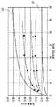
[도 6] 부하면압에 대한 접촉면적률의 값을 나타낸 도.
[도 7] 부하면압에 대한 접촉폭의 값을 나타낸 도.
[도 8] (a) 제2 실시 형태에 관한 사판을 나타낸 정면도. (b) 제3 실시 형태에 관한 사판을 나타낸 정면도.
[도 9] (a) 제4 실시 형태에 관한 사판(시험편)의 표면의 형상을 나타낸 정면도. (b) 제5 실시 형태에 관한 사판(시험편)의 표면의 형상을 나타낸 정면도.BRIEF DESCRIPTION OF THE DRAWINGS Fig. 1 is a partial cross-sectional view of a side view showing a schematic structure of a compressor according to a first embodiment; Fig.
FIG. 2 is a partial cross-sectional view showing a contact portion between the swash plate and the shoe.
3 is a front view showing the shape of the convex portion of the swash plate.
4 is a side view showing a schematic configuration of a contact surface observation apparatus.
[Fig. 5] (a) is a perspective view showing the shape of the surface of the swash plate (test piece). (b) a front view showing the shape of the surface of the swash plate (test piece).
6 is a view showing a value of contact area ratio with respect to a load surface pressure.
7 is a view showing the value of the contact width with respect to the load surface pressure.
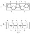
8 (a) is a front view showing a swash plate according to the second embodiment. Fig. (b) is a front view showing the swash plate according to the third embodiment.
9 (a) is a front view showing the shape of the surface of a swash plate (test piece) according to the fourth embodiment. (b) is a front view showing the shape of the surface of the swash plate (test piece) according to the fifth embodiment.
이하의 설명에서 이용하는 도는 모식도이며, 설명의 편의 상, 각부의 치수 등을 적당 과장하여 나타내 보이고 있다.The drawings used in the following description are schematic views, and the dimensions of the respective parts are exaggerated for convenience of explanation.
이하에서는, 도 1 및 도 2를 이용하여, 본 발명의 제1 실시 형태에 관한 컴프레서(1)의 구성의 개략에 대해 설명한다. 컴프레서(1)는, 주로 회전축(2), 사판(斜板)(3), 피스톤(4) 및 슈(shoe)(5)를 구비한다.Hereinafter, the outline of the configuration of the compressor 1 according to the first embodiment of the present invention will be described with reference to Figs. 1 and 2. Fig. The compressor 1 mainly includes a
도 1에 나타내는 회전축(2)은, 도시하지 않은 하우징에 회전 가능하게 지지를 받는다. 회전축(2)은, 도시하지 않은 구동원으로부터의 동력에 의해서 회전할 수 있다.The
사판(3)은, 원형 평판상으로 형성된다. 사판(3)의 중앙 부분에는, 회전축(2)이 삽통된다. 사판(3)은, 회전축(2)의 축선 방향에 대해서 경사한 상태로, 해당 회전축(2)의 중도부(中途部)에 고정된다.The swash plate (3) is formed in a circular plate shape. In the central portion of the
또한, 사판(3)의 상세한 구성에 대해서는 후술한다.The detailed configuration of the
피스톤(4)은, 상기 하우징에 형성된 도시하지 않은 복수의 실린더 보아(bore) 내에 각각 배치된다. 피스톤(4)은, 회전축(2)의 축선 방향을 따라서 접동(왕복동) 가능하게 설치된다. 피스톤(4)에는 요부(凹部)(4a)가 형성된다.The
요부(4a)는, 피스톤(4)의 내부에 형성된다. 요부(4a)는 대략 반구상으로 형성된다. 요부(4a)는, 회전축(2)의 축선 방향을 따라서 대향하도록, 각 피스톤(4)에 한 쌍씩 형성된다.The
도 1 및 도 2에 나타내는 슈(5)는, 대략 반구상으로 형성된다. 구체적으로는, 슈(5)는, 주로 평면부(5a) 및 구면부(5b)를 구비한다.The
평면부(5a)는, 평탄하게 형성되는 면이다. 평면부(5a)는, 대략 원형상으로 형성된다.The
구면부(5b)는, 대략 반구상으로 형성되는 면이다. 구면부(5b)는, 평면부(5a)의 반대 측에, 해당 평면부(5a)와 연속하도록 형성된다.The
슈(5)는, 철계, 동계, 알루미늄계 재료 외에, 소결 재료나 수지 재료 등에 의해서 제조된다. 특히, 슈(5)는 SUJ2에 단조나 전조를 시행하여 제조하는 것이 바람직하다.The
이와 같이 형성된 슈(5)는, 피스톤(4)의 요부(4a) 내에 각각 배치된다. 이 때, 슈(5)의 구면부(5b)와 요부(4a)가 요동 가능하게 접하도록 배치된다. 이것에 의해서, 1개의 피스톤(4)에 배치된 2개의 슈(5)는, 서로 평면부(5a)를 대향시킨 상태로 배치된다. 해당 2개의 슈(5)의 평면부(5a)의 사이에 사판(3)의 외주부 근방이 협지된다.The
이와 같이 구성된 컴프레서(1)에서 회전축(2)이 회전하면, 해당 회전축(2)와 함께 사판(3)도 회전한다. 사판(3)은 회전축(2)의 축선 방향에 대해서 기울고 있기 때문에, 해당 사판(3)은 슈(5)를 개입시켜 피스톤(4)를 축선 방향으로 왕복동(접동)시키게 된다. 이 때, 슈(5)의 평면부(5a)는 사판(3)의 표면을 접동한다.When the
이하에서는, 도 2 및 도 3을 이용하여, 사판(3)의 상세한 구성에 대해 설명한다.Hereinafter, the detailed structure of the
사판(3)은, 주로 기재(10) 및 코팅층(20)을 구비한다.The
기재(10)는, 원형 평판상으로 형성되는 부재이다. 기재(10)는, 철계, 동계, 알루미늄계 재료 등에 의해서 제조된다.The
코팅층(20)은, 기재(10)의 표면(슈(5)와 대향하는 면)에 형성된다. 또, 실제로는 기재(10)의 양측면에 코팅층(20)이 형성되지만, 이하의 설명에서는 기재(10)의 일방의 측면에 형성된 코팅층(20)에 주목하여 설명을 실시한다. 코팅층(20)은, 열강화성 수지 바인더 또는 열가소성 수지 바인더에 고체 윤활재를 첨가한 것을 이용하여 형성된다.The
열강화성 수지 바인더로서는, 예를 들면 폴리이미드계 수지(polyimide resin, PI), 폴리아미드이미드계 수지(polyamide-imide type resin, PAI), 에폭시 수지(epoxy resin), 페놀 수지(phenol resin), 폴리아미드(polyamide)(나일론), 엘라스토머(elastomer) 등을 들 수 있다. 열가소성 수지 바인더로서는, 예를 들면 폴리벤조이미다조르 수지(polybenzimidazole resin, PBI), 폴리에테르에테르 케톤 수지(polyetheretherketone resin, PEEK) 등을 들 수 있다.Examples of the thermosetting resin binder include a polyimide resin (PI), a polyamide-imide type resin (PAI), an epoxy resin, a phenol resin, a poly Polyamide (nylon), elastomer, and the like. Examples of the thermoplastic resin binder include polybenzimidazole resin (PBI), polyetheretherketone resin (PEEK), and the like.
고체 윤활재로서는, 예를 들면 2 황화 몰리브덴(molybdenum disulfide, MoS2), 폴리테트라플루오르 에틸렌(polytetrafluoroethylene, PTFE), 2 황화 텅스텐(tungsten disulfide, WS2), 육방정질화 붕소(hexagonal boron nitride, h-BN), 흑화 흑연(fluorinated graphite, CF), 불소계 수지(fluorine resin) 등을 들 수 있다. 고체 윤활재의 입경은 15μm 이하, 바람직하게는 0.2~10μm로 하는 것이 바람직하고, 그 배합비는 5~80 wt%로 하는 것이 바람직하다.Examples of the solid lubricant include molybdenum disulfide (MoS2), polytetrafluoroethylene (PTFE), tungsten disulfide (WS2), hexagonal boron nitride (h-BN) , Fluorinated graphite (CF), fluorine resin, and the like. The solid lubricant preferably has a particle diameter of 15 mu m or less, preferably 0.2 to 10 mu m, and the blending ratio thereof is preferably 5 to 80 wt%.
또 코팅층(20)에 경질 입자를 첨가해도 좋다. 경질 입자로서는, 알루미나나 실리카 등의 산화물, 질화 실리콘(SiN) 등의 질화물, 탄화 실리콘(SiC) 등의 탄화물, 유화 아연(ZnS) 등의 황화물을 들 수 있다. 경질 입자의 입경은 0.01~3μm로 하는 것이 바람직하고, 그 배합비는 0.2~7 wt%로 하는 것이 바람직하다.Hard particles may be added to the
코팅층(20)은, 주로 구부(溝部)(21) 및 철부(凸部)(22)를 구비한다.The
구부(21)는, 코팅층(20)의 표면에 형성된다. 구부(21)는, 사판(3)과 동심원상(同心円狀)으로 복수 형성된다. 구부(21)는, 기재(10)의 표면에 코팅층(20)을 형성한 다음에, 해당 코팅층(20)에 기계 가공(절삭 가공 등)을 시행함으로써 형성된다. 절삭 가공에 의해서 구부(21)를 형성하는 경우, 절삭 공구를 이용하여 코팅층(20)의 표면이 원환상(円環狀)으로 절삭된다. 이 때, 인접하는 구부(21) 간의 거리(피치)는 적당 설정할 수 있다. 또 구부(21)의 단면 형상(도 2 참조)은, 절삭 공구의 칼끝의 형상과 대략 동일하다.The
철부(22)는, 코팅층(20)의 표면에 형성된다. 철부(22)는, 코팅층(20)에 동심원상의 구부(21)를 복수 형성함으로써, 인접하는 구부(21)의 사이에 형성된다. 이것에 의해서 철부(22)는, 코팅층(20)의 표면에, 동심원상으로 복수 형성되게 된다.The
이와 같이 구성된 사판(3)이 슈(5)와 접동할 때, 코팅층(20)의 철부(22)의 선단이 슈(5)의 평면부(5a)와 접하게 된다. 이 때, 슈(5)에 의해서 코팅층(20)이 소정의 힘(압력)으로 밀리기 때문에, 철부(22)의 선단은 탄성변형에 의해 약간 무너지고 있다.The front end of the
이와 같이 구성된 컴프레서(1)에서, 사판(3)의 철부(22)가 적당 탄성변형 하거나 마모하거나 함으로써, 슈(5)와의 초기 순응성(conformability)을 향상시킬 수 있다. 또, 슈(5)가 복수의 철부(22)와 접하기 때문에, 해당 슈(5)에 의한 면압이 분산됨으로써 철부(22)의 탄성변형을 작게 억제하는 것이 가능하고, 과도한 마모를 억제할 수 있다. 또, 구부(21) 내에 윤활유를 확보하는 것이 가능하고, 접동에 의한 온도 상승을 억제함과 동시에 접동 특성을 향상시킬 수 있다.In the compressor 1 constructed as described above, the initial conformability with the
본 실시 형태에 관한 컴프레서(1)에서는, 특히 코팅층(20)의 소모(마모)를 억제하는 관점으로부터 사판(3)의 상세한 형상을 결정하고 있다. 이하에서는, 해당 사판(3)의 구성에 대해서, 보다 상세하게 설명한다.The compressor 1 according to the present embodiment determines the detailed shape of the
사판(3)에 대해 보다 상세하게 설명하기 위해서, 우선은 도 4를 이용하여, 해당 사판(3)의 접촉면(다른 부재와 접촉하고 있는 면)을 측정하기 위한 장치(접촉면 관찰 장치(100)(접촉면 현미경))의 개략에 대해 설명한다.In order to describe the
접촉면 관찰 장치(100)는, 고체끼리의 접촉면을 관찰하기 위한 장치이다. 접촉면 관찰 장치(100)는, 주로 프리즘(101) 및 광원(102)을 구비한다.The contact
프리즘(101)은, 적당의 투명한 재료로 형성된 부재이다. 프리즘(101)은 대략 삼각주상(三角柱狀)으로 형성된다. 프리즘(101)에는, 사각 평면상(矩形平面狀)의 평면부(101a)(3개의 측면 중 하나)가 형성된다. 프리즘(101)은, 평면부(101a)를 상방으로 향한 상태로 배치된다.The
광원(102)은, 광을 발하는 것이다. 광원(102)은, 프리즘(101)의 하부에 배치된다. 광원(102)으로부터의 광은, 프리즘(101)의 하부(보다 상세하게는, 기울기 45도 하방)로부터 해당 프리즘(101)(평면부(101a))을 향해서 조사된다.The
이러한 접촉면 관찰 장치(100)에서, 관찰의 대상이 되는 부재가, 프리즘(101)의 평면부(101a)에 상방으로부터 소정의 힘(압력)으로 압부된다. 이 때의 압력을, 이하에서는 부하면압(負荷面壓)이라 한다. 본 실시 형태에서는, 사판(3)(코팅층(20))이 관찰의 대상이 되기 때문에, 해당 사판(3)(코팅층(20))이 프리즘(101)의 평면부(101a)에 압부된다. 또 이 때에는, 원형 평판상의 사판(3) 전체가 아니고, 사판(3)의 일부분을 사각형(矩形狀)으로 잘라낸 시험편이 이용된다. 이하, 접촉면 관찰 장치(100)에 의한 관찰에 이용되는 사판(3)이란, 해당 시험편을 의미하는 것으로 한다.In this contact
이 상태로 광원(102)으로부터 광을 조사하여, 사판(3)의 표면(코팅층(20))에서 반사한 광(반사광)을 관찰한다. 해당 반사광의 관찰은, 목시(目視)나 카메라 등을 이용하여 행해진다. 해당 반사광을 관찰함으로써, 사판(3)의 접촉면을 상세하게 관찰할 수 있다.In this state, light is irradiated from the
다음으로 도 5를 이용하여, 접촉면 관찰 장치(100)에 의해서 관찰되는 사판(3)의 표면(코팅층(20))의 각부의 치수의 정의를 설명한다.Next, with reference to Fig. 5, the definition of the dimensions of each part of the surface (coating layer 20) of the
전술과 같이, 다른 부재(프리즘(101))가 압부됨으로써 코팅층(20)에 힘이 더해지면, 철부(22)의 선단은 탄성변형에 의해 약간 무너진다. 이 상태에서는, 철부(22)의 선단에 세장(細長) 평면상의 부분, 즉 프리즘(101)과의 접촉면(도 5에서의 사선 부분의 면)이 형성되게 된다. 이하에서는, 해당 접촉면의 폭(단수 방향의 폭)을 B(mm)라고 정의한다. 이하에서는 B를 접촉폭이라고 칭한다.As described above, when a force is applied to the
또, 사판(3)(시험편)의 코팅층(20)에는 복수의 철부(22)가 형성되어 있기 때문에, 상술의 프리즘(101)과의 접촉면도 복수 형성되게 된다. 따라서 이하에서는, 각 접촉면의 면적을 Si(mm2)라고 정의한다. 도 5에서는, 4개의 접촉면(철부(22)의 선단)을 예시하고 있으므로, i=1, 2, 3, 4로서 S1, S2, S3 및 S4를 예시하고 있다.Since a plurality of
또, 코팅층(20)에 프리즘(101)이 압부된 상태에서의 철부(22)의 높이를 H(mm)라고 정의한다. 보다 상세하게는, 높이(H)란, 구부(21)의 저부로부터 철부(22)의 선단(접촉면)까지의 높이를 의미한다.The height of the
또, 코팅층(20)에 프리즘(101)이 압부된 상태에서의 코팅층(20)의 두께를 T(mm)라고 정의한다. 보다 상세하게는, 두께(T)란, 철부(22)의 선단(접촉면)으로부터, 해당 철부(22)와는 반대측의 면까지의 두께를 의미한다.The thickness of the
이하에서는, 본 실시 형태에 관한 코팅층(20)을 접촉면 관찰 장치(100)로 관찰했을 때의, 해당 코팅층(20)의 각부의 치수의 구체적인 값에 대해 설명한다. 또, 구체적으로는, 사판(3)(시험편)은 프리즘(101)의 평면부(101a)에 대해서 30(MPa)의 압력으로 압부되는 것으로 한다.Hereinafter, specific values of the dimensions of the corner portions of the
이 경우에서, 본 실시 형태에 관한 코팅층(20)은, 이하의 식(1) 및 (2)을 만족하도록 설정되어 있다.In this case, the
0.01≤B≤0.06···(1)0.01? B? 0.06 (1)
10≤S≤40···(2)10? S? 40 (2)
여기서, S란, 기준면적(Sc)에 대한 각 접촉면의 면적(Si)의 총화(총면적)의 비율(%)을 의미한다. 이하에서는 S를 접촉면적률로 칭한다. 또 기준면적(Sc)이란, 접촉면 관찰 장치(100)에 의한 관찰의 대상이 되는 사판(3)의 면적, 즉 시험편의 면적을 의미한다. 따라서, 접촉면적률(S)은, 「S=ΣSi/Sc(%)」의 식에서 산출할 수 있다.Here, S means the ratio (%) of the total area (total area) of the area Si of each contact surface to the reference area Sc. Hereinafter S is referred to as contact area ratio. The reference area Sc means the area of the
또한, 본 실시 형태에서는, 복수의 철부(22)의 접촉폭(B)이 모두 같은 값인 상태를 도시하고 있지만(도 5 참조), 복수의 철부(22)의 접촉폭(B)은 서로 차이가 나도 좋다. 이 경우, 모든 접촉폭(B)이 상기 식(1)을 만족시키는 것이 바람직하다.Although the contact widths B of the plurality of
또, 본 실시 형태에 관한 코팅층(20)은, 이하의 식(3) 및 (4)를 만족하도록 설정되어 있다.The
0.001≤H≤0.01· · · (3)0.001? H? 0.01 (3)
0.005≤T≤0.06· · · (4)0.005? T? 0.06 (4)
이와 같이 코팅층(20)을 설정함으로써, 사판(3)의 표면(철부(22))이 적당히 탄성변형 하여, 해당 철부(22)의 선단(접촉면)의 유막(윤활막)을 보관 유지하기 쉬워진다. 이것에 의해서, 코팅층(20)의 소모(마모)를 억제할 수 있다. 또, 해당 접촉면에서 탄성 유체 윤활이 생기고, 유막 면적이 넓어져서 면압을 저하시킴으로써 양호한 윤활 상태를 유지할 수 있다. 이와 같이 하여, 본 실시 형태에 관한 컴프레서(1)(사판(3))에서는, 전단 저항이나 발열 등의 저감을 도모하는 것이 가능하고, 나아가서는 마찰력의 저감이나 마모의 저감을 도모할 수 있다.By setting the
도 6 및 도 7에는, 상기 식(1)~(4)를 만족하도록 설정된 코팅층(20)을 구비하는 사판(3)을, 접촉면 관찰 장치(100)로 관찰한 예를 나타내고 있다.6 and 7 show an example in which the
구체적으로는, 도 6에는, 부하면압에 대한 접촉면적률(S)의 값을 나타내고 있다. 또 도 6에는, 다른 기호를 이용하여, 다른 재료(기재(10) 및 코팅층(20)의 재료)를 이용하여 형성된 3 종류의 사판(3)의 데이터를 나타내고 있다. 또 도 6에는, 부하면압이 30(MPa) 일 때에 접촉면적률(S)=10(%)을 통과하는 대수관계의 그래프 L1와, 부하면압이 30(MPa) 일 때에 접촉면적률(S)=40(%)을 통과하는 대수관계의 그래프 L2를 아울러 나타내 보이고 있다.Specifically, FIG. 6 shows the value of the contact surface area ratio S with respect to the load surface pressure. 6 shows data of three kinds of
도 6으로부터 알 수 있듯이, 이 예에서는, 부하면압이 30(MPa) 일 때에 상기 식(2)을 만족하도록 사판(3)이 설정되어 있다. 특히 이 예에서는, 접촉면적률(S)이 그래프 L1와 그래프 L2의 사이의 영역 내에 포함되도록, 사판(3)이 설정되어 있다.As can be seen from Fig. 6, in this example, the
또 도 7에는, 부하면압에 대한 접촉폭(B)의 값을 나타내고 있다. 또 도 7에는, 다른 기호를 이용하여, 다른 철부(22)의 높이(H) 및 코팅층(20)의 두께(T)를 가지도록 설정된 3 종류의 사판(3)의 데이터를 나타내고 있다. 또 도 7에는, 부하면압이 30(MPa) 일 때에 접촉폭(B)=0.01(mm)을 통과하는 대수관계의 그래프 L3와, 부하면압이 30(MPa) 일 때에 접촉폭(B)=0.06(mm)을 통과하는 대수관계의 그래프 L4를 아울러 나타내 보이고 있다.7 shows the value of the contact width B with respect to the load surface pressure. 7 shows data of three types of
도 7으로부터 알 수 있듯이, 이 예에서는, 부하면압이 30(MPa) 일 때에 상기 식(1)을 만족하도록 사판(3)이 설정되어 있다. 특히 이 예에서는, 접촉폭(B)이 그래프 L3와 그래프 L4의 사이의 영역 내에 포함되도록, 사판(3)이 설정되어 있다.As can be seen from Fig. 7, in this example, the
이상과 같이, 본 실시 형태에 관한 사판(3)(컴프레서용 사판)은, 평판상의 기재(10)와, 기재(10)의 표면에 형성되어, 선상으로 형성된 철부(22)를 구비하는 코팅층(20)을 구비하는 사판(3)에서, 프리즘(101)(압압 부재)에 형성된 평면부(101a)를 코팅층(20)에 30 MPa의 압력으로 압부하였을 때에, 이하의 식을 만족하도록 형성된 것이다.As described above, the swash plate 3 (compressor swash plate) according to the present embodiment is a swash plate 3 (compressor swash plate) according to the present embodiment, which comprises a
0.01≤B≤0.06···(1)0.01? B? 0.06 (1)
10≤S≤40···(2)10? S? 40 (2)
여기서, B는 철부(22)가 평면부(101a)에 대해서 접촉하는 면의 폭(mm), S는 기준면적(Sc)(코팅층(20) 중 평면부(101a)가 압부되는 부분의 면적)에 대한 각 접촉면의 면적(Si)의 총화(철부(22)가 평면부(101a)와 접촉하는 면의 총면적)의 비율(%)이다.Where B is the width (mm) of the surface where the
이와 같이 구성함으로써, 코팅층(20)의 소모를 억제할 수 있다.By such a constitution, the consumption of the
즉, 이와 같이 코팅층(20)을 설정함으로써, 사판(3)의 표면(철부(22))이 적당히 탄성변형 하고, 해당 철부(22)의 선단(접촉면)의 유막(윤활막)을 보관 유지하기 쉬워진다. 이것에 의해서, 코팅층(20)의 소모(마모)를 억제할 수 있다.That is, by setting the
또, 코팅층(20)은, 이하의 식을 만족하도록 형성되는 것이다.The
0.001≤H≤0.01···(3)0.001? H? 0.01 (3)
0.00≤T≤0.06···(4)0.00? T? 0.06 (4)
여기서, H는 평면부(101a)가 코팅층(20)에 압부되었을 때의 철부(22)의 높이(mm), T는 평면부(101a)가 코팅층(20)에 압부되었을 때의 해당 코팅층(20)의 두께(mm)이다.Where H is the height (mm) of the
이와 같이 구성하는 것으로써, 코팅층(20)의 소모를 억제할 수 있다.By such a constitution, the consumption of the
즉, 이와 같이 코팅층(20)을 설정함으로써, 사판(3)의 표면(철부(22))이 적당히 탄성변형 하고, 해당 철부(22)의 선단(접촉면)의 유막(윤활막)을 보관 유지하기 쉬워진다. 이것에 의해서, 코팅층(20)의 소모(마모)를 억제할 수 있다.That is, by setting the
또한, 절삭 가공에 의해서 구부(21)를 형성하는 경우에는, 절삭 공구의 이송량(피치)을 조절함으로써, 철부(22)의 높이(H) 및 코팅층(20)의 두께(T)를 적당 조절할 수 있다.The height H of the
또, 철부(22)는, 복수의 동심원상으로 형성되는 것이다.The
이와 같이 구성함으로써, 코팅층(20)의 소모를 억제할 수 있다.By such a constitution, the consumption of the
즉, 인접하는 철부(22)의 사이에 적당한 간격을 비움으로써, 해당 철부(22)의 사이에 윤활유를 확보하는 것이 가능하고, 접동 특성을 향상시킬 수 있다. 특히, 본 실시 형태와 같이 사판(3)과 동심원상으로 철부(22)를 형성함으로써, 해당 철부(22)가 형성될 방향과, 슈(5)가 접동할 방향을 대략 일치시킬 수 있다. 이에 따라, 대략 일정한 면압으로 슈(5)와 사판(3)을 접동시키는 것이 가능하고, 코팅층(20)의 소모를 효과적으로 억제할 수 있다.In other words, it is possible to secure lubricating oil between the
또, 본 실시 형태에 관한 컴프레서(1)는, 사판(3)과, 사판(3)을 회전 가능하게 지지하는 회전축(2)과, 사판(3)의 회전에 수반하여 왕복동하는 피스톤(4)을 구비하는 것이다.The compressor 1 according to the present embodiment includes a
이와 같이 구성함으로써, 코팅층(20)의 소모를 억제할 수 있다.By such a constitution, the consumption of the
또한, 본 실시 형태에 관한 사판(3)은, 본 발명에 관한 컴프레서용 사판의 실시의 한 형태이다.The
또, 본 실시 형태에 관한 프리즘(101)은, 본 발명에 관한 압압 부재의 실시의 한 형태이다.The
이상, 본 발명의 실시 형태를 설명했지만, 본 발명은 상기 구성으로 한정되는 것이 아니고, 특허청구범위에 기재된 발명의 범위 내에서 여러 가지의 변경이 가능하다.Although the embodiment of the present invention has been described above, the present invention is not limited to the above-described configuration, and various modifications are possible within the scope of the invention described in the claims.
이하에서는, 본 발명에 관한 컴프레서용 사판의 다른 실시 형태에 대해 설명한다.Hereinafter, another embodiment of the swash plate for a compressor according to the present invention will be described.
도 8(a)에 나타내는 제2 실시 형태에 관한 사판(3A)과 같이, 철부(22)를 소용돌이상(渦卷狀)(나사상)으로 형성하는 것도 가능하다. 이 경우, 구부(21)를 소용돌이상으로 형성함으로써, 철부(22)도 소용돌이상(나사상)으로 형성되게 된다.It is also possible to form the
이상과 같이, 제2 실시 형태에 관한 철부(22)는, 소용돌이상으로 형성되는 것이다.As described above, the
이와 같이 구성함으로써, 코팅층(20)의 소모를 억제할 수 있다.By such a constitution, the consumption of the
즉, 철부(22)와 인접하는 소용돌이상의 구부(21)에 윤활유를 확보하는 것이 가능하고, 접동 특성을 향상시킬 수 있다.Namely, it is possible to secure lubricating oil at the spiral-shaped
도 8(b)에 나타내는 제3 실시 형태에 관한 사판(3B)과 같이, 철부(22)를 복수의 동심원 호상(弧狀)으로 형성하는 것도 가능하다. 구체적으로는, 사판(3B)의 철부(22)는, 동심원의 일부분(중심을 사이에 두고 대향하는 2개의 부분, 이하에서는 분단부라고 칭한다)을 분단한 것 같은 형상으로 형성된다. 이것에 의해서, 각 철부(22)는, 중심각이 대략 180도의 원호상으로 형성된다. 또 지름 방향으로 인접하는 철부(22)의 분단부끼리는, 서로 지름 방향으로 대향하지 않게 형성된다. 구체적으로는, 지름 방향으로 인접하는 철부(22)의 분단부끼리는, 서로 둘레 방향으로 소정의 각도(도 8(b)에서는 90도)만큼 어긋난 위치에 형성된다. 이것에 의해서, 구부(21)에 윤활유를 보관 유지하기 쉽게 할 수 있다.It is also possible to form the
도 9(a)에 나타내는 제4 실시 형태에 관한 사판(3C)과 같이, 철부(22)를 복수의 원환상으로 형성하는 것도 가능하다. 구체적으로는, 복수의 철부(22)는, 대략 동일 반경을 갖는 원환상으로 형성된다. 각 철부(22)는 서로 다른 점을 중심으로, 중복되지 않게 형성된다.It is also possible to form the
이상과 같이, 제4 실시 형태에 관한 철부(22)는, 서로 다른 점을 중심으로 하는 복수의 원환상으로 형성되는 것이다.As described above, the
이와 같이 구성함으로써, 코팅층(20)의 소모를 억제할 수 있다.By such a constitution, the consumption of the
즉, 철부(22)의 내측에 윤활유를 확보하는 것이 가능하고, 접동 특성을 향상시킬 수 있다.In other words, lubricating oil can be secured inside the
도 9(b)에 나타내는 제5 실시 형태에 관한 사판(3D)과 같이, 철부(22)를 복수의 직선상으로 형성하는 것도 가능하다. 구체적으로는, 철부(22)는, 소정의 길이를 갖는 직선상으로 형성된다. 각 철부(22)는 서로 중복되지 않게 형성된다. 제5 실시 형태에서는, 인접하는 철부(22)는, 서로 다른 방향(90도 다른 방향)을 따라서 연장되도록 형성된다.It is also possible to form the
또한, 상기 각 실시 형태에 한정하지 않고, 철부(22)의 형상은 임의의 형상으로 할 수 있다.The shape of the
산업상의 이용 가능성Industrial availability
본 발명은, 컴프레서용 사판 및 그것을 구비하는 컴프레서에 적용할 수 있다.INDUSTRIAL APPLICABILITY The present invention can be applied to a compressor swash plate and a compressor equipped with the swash plate.
1 컴프레서
2 회전축
3 사판(斜板)
4 피스톤
5 슈(shoe)
10 기재(基材)
20 코팅층
21 구부(溝部)
22 철부(凸部)1 compressor
2 rotating shaft
3 swash plate
4 piston
5 shoe
10 Base material
20 coating layer
21 groove portion
22 convex portion
Claims (6)
Translated fromKorean상기 기재의 표면에 형성되어, 선상으로 형성된 철부를 구비하는 코팅층,
을 구비하는 컴프레서용 사판에 있어서,
압압 부재에 형성된 평면부를 상기 코팅층에 30 MPa의 압력으로 압부하였을 때, 이하의 식을 만족하도록 형성된 컴프레서용 사판.
0.01≤B≤0.06···(1)
10≤S≤40···(2)
0.001≤H≤0.01···(3)
0.005≤T≤0.06···(4)
여기서, B는 상기 철부가 상기 평면부에 대해서 접촉하는 면의 폭(mm), S는 상기 코팅층 중 상기 평면부가 압부되는 부분의 면적에 대한, 상기 철부가 상기 평면부와 접촉하는 면의 총면적의 비율(%), H는 상기 평면부가 상기 코팅층에 압부되었을 때의 상기 철부의 높이(mm), T는 상기 평면부가 상기 코팅층에 압부되었을 때의 해당 코팅층의 두께(mm)이다.
A flat substrate,
A coating layer formed on the surface of the substrate and having convex portions formed in a line,
Wherein the swash plate for a compressor includes:
Wherein when the flat portion formed on the pressing member is pressed against the coating layer at a pressure of 30 MPa, the following expression is satisfied.
0.01? B? 0.06 (1)
10? S? 40 (2)
0.001? H? 0.01 (3)
0.005? T? 0.06 (4)
Where B is the width (mm) of the surface of the convex portion contacting the plane portion, S is the total area of the surface of the convex portion contacting the plane portion, H is a height (mm) of the convex portion when the flat portion is pressed against the coating layer, and T is a thickness (mm) of the coating layer when the flat portion is pressed against the coating layer.
상기 철부는,
복수의 동심원상으로 형성되는,
컴프레서용 사판.
The method according to claim 1,
The convex portion,
A plurality of concentric circles,
Compressor swash plate.
상기 철부는,
소용돌이상으로 형성되는,
컴프레서용 사판.
The method according to claim 1,
The convex portion,
Which is formed in a spiral shape,
Compressor swash plate.
상기 철부는,
서로 다른 점을 중심으로 하는 복수의 원환상으로 형성되는,
컴프레서용 사판.
The method according to claim 1,
The convex portion,
And is formed as a plurality of annular shapes centering on different points,
Compressor swash plate.
상기 컴프레서용 사판을 회전 가능하게 지지하는 회전축과,
상기 컴프레서용 사판의 회전에 수반하여 왕복동되는 피스톤,
을 구비하는 컴프레서.A compressor for a compressor as set forth in any one of claims 1 to 4,
A rotary shaft for rotatably supporting the compressor swash plate,
A piston reciprocating with the rotation of the compressor swash plate,
.
Applications Claiming Priority (3)
| Application Number | Priority Date | Filing Date | Title |
|---|---|---|---|
| JP2015196293AJP6177852B2 (en) | 2015-10-01 | 2015-10-01 | Swash plate for compressor and compressor having the same |
| JPJP-P-2015-196293 | 2015-10-01 | ||
| PCT/JP2016/078571WO2017057430A1 (en) | 2015-10-01 | 2016-09-28 | Compressor swashplate and compressor provided with same |
Publications (2)
| Publication Number | Publication Date |
|---|---|
| KR20180037286A KR20180037286A (en) | 2018-04-11 |
| KR101867261B1true KR101867261B1 (en) | 2018-06-12 |
Family
ID=58423926
Family Applications (1)
| Application Number | Title | Priority Date | Filing Date |
|---|---|---|---|
| KR1020187008595AActiveKR101867261B1 (en) | 2015-10-01 | 2016-09-28 | A compressor swash plate and a compressor equipped with the swash plate |
Country Status (6)
| Country | Link |
|---|---|
| US (1) | US10184463B2 (en) |
| JP (1) | JP6177852B2 (en) |
| KR (1) | KR101867261B1 (en) |
| CN (1) | CN108138758B (en) |
| DE (1) | DE112016004511T5 (en) |
| WO (1) | WO2017057430A1 (en) |
Families Citing this family (3)
| Publication number | Priority date | Publication date | Assignee | Title |
|---|---|---|---|---|
| US11498990B2 (en) | 2017-03-30 | 2022-11-15 | Zeon Corporation | Crosslinkable rubber composition and crosslinked rubber |
| JP2019082148A (en)* | 2017-10-31 | 2019-05-30 | 大豊工業株式会社 | Swash plate |
| JPWO2023248962A1 (en)* | 2022-06-23 | 2023-12-28 |
Citations (2)
| Publication number | Priority date | Publication date | Assignee | Title |
|---|---|---|---|---|
| JP4376519B2 (en)* | 2001-03-16 | 2009-12-02 | 大豊工業株式会社 | Swash plate for compressor |
| KR20130086240A (en)* | 2010-11-24 | 2013-07-31 | 다이호 고교 가부시키가이샤 | Swash plate compressor |
Family Cites Families (11)
| Publication number | Priority date | Publication date | Assignee | Title |
|---|---|---|---|---|
| JP3305979B2 (en) | 1997-03-18 | 2002-07-24 | 大同メタル工業株式会社 | Plain bearing |
| JP2001165167A (en)* | 1999-12-10 | 2001-06-19 | Taiho Kogyo Co Ltd | Plain bearing |
| JP2004211859A (en) | 2003-01-08 | 2004-07-29 | Taiho Kogyo Co Ltd | Plain bearing |
| JP2006070838A (en)* | 2004-09-03 | 2006-03-16 | Taiho Kogyo Co Ltd | Sliding member |
| BRPI0519787A2 (en)* | 2004-12-28 | 2009-03-17 | Taiho Kogyo Co Ltd | shoe |
| EP1854897A4 (en)* | 2005-01-17 | 2012-04-25 | Taiho Kogyo Co Ltd | METHOD FOR MANUFACTURING A SLIPPER MEMBER |
| JP4075899B2 (en)* | 2005-03-23 | 2008-04-16 | 大豊工業株式会社 | Manufacturing method of swash plate |
| JP3931990B2 (en)* | 2005-04-27 | 2007-06-20 | 大豊工業株式会社 | Sliding device |
| JP5298838B2 (en)* | 2008-12-25 | 2013-09-25 | 大豊工業株式会社 | Swash plate and its manufacturing method |
| JP2011089495A (en)* | 2009-10-23 | 2011-05-06 | Taiho Kogyo Co Ltd | Swash plate |
| JP5621990B2 (en)* | 2011-12-22 | 2014-11-12 | 大豊工業株式会社 | Sliding member |
- 2015
- 2015-10-01JPJP2015196293Apatent/JP6177852B2/enactiveActive
- 2016
- 2016-09-28DEDE112016004511.5Tpatent/DE112016004511T5/enactivePending
- 2016-09-28USUS15/751,952patent/US10184463B2/enactiveActive
- 2016-09-28KRKR1020187008595Apatent/KR101867261B1/enactiveActive
- 2016-09-28WOPCT/JP2016/078571patent/WO2017057430A1/ennot_activeCeased
- 2016-09-28CNCN201680056578.6Apatent/CN108138758B/enactiveActive
Patent Citations (2)
| Publication number | Priority date | Publication date | Assignee | Title |
|---|---|---|---|---|
| JP4376519B2 (en)* | 2001-03-16 | 2009-12-02 | 大豊工業株式会社 | Swash plate for compressor |
| KR20130086240A (en)* | 2010-11-24 | 2013-07-31 | 다이호 고교 가부시키가이샤 | Swash plate compressor |
Also Published As
| Publication number | Publication date |
|---|---|
| DE112016004511T5 (en) | 2018-07-19 |
| WO2017057430A1 (en) | 2017-04-06 |
| US10184463B2 (en) | 2019-01-22 |
| KR20180037286A (en) | 2018-04-11 |
| US20180230980A1 (en) | 2018-08-16 |
| JP2017067048A (en) | 2017-04-06 |
| JP6177852B2 (en) | 2017-08-09 |
| CN108138758B (en) | 2019-08-16 |
| CN108138758A (en) | 2018-06-08 |
Similar Documents
| Publication | Publication Date | Title |
|---|---|---|
| KR101867261B1 (en) | A compressor swash plate and a compressor equipped with the swash plate | |
| JP6317965B2 (en) | bearing | |
| KR102204289B1 (en) | Resin composition and sliding member | |
| US8579298B2 (en) | Sealing device | |
| JP2015183798A (en) | bearing | |
| JP5607754B2 (en) | Swash plate compressor | |
| JP6706184B2 (en) | Swash plate for compressor | |
| US11352581B2 (en) | Resin composition and sliding member | |
| JP2018035838A (en) | Thrust washer | |
| WO2007091564A1 (en) | Swash plate for swash plate-type compressor and swash plate-type compressor | |
| WO2017094810A1 (en) | Sliding member and swash plate type compressor | |
| JP6706185B2 (en) | Swash plate for compressor | |
| JP2018091142A (en) | Compressor swash plate | |
| KR102237730B1 (en) | compressor shoe | |
| JP2017141708A (en) | Swash plate for compressor and swash plate compressor | |
| JP6283238B2 (en) | bearing | |
| JP6313681B2 (en) | Swash plate compressor hemispherical shoe and swash plate compressor | |
| JP2008133814A (en) | Swash plate of swash plate-type compressor, and swash plate-type compressor | |
| JP2015183797A (en) | bearing | |
| JP2019082216A (en) | Sliding member | |
| JP2016121533A (en) | Slide member and compressor |
Legal Events
| Date | Code | Title | Description |
|---|---|---|---|
| A201 | Request for examination | ||
| A302 | Request for accelerated examination | ||
| PA0105 | International application | Patent event date:20180327 Patent event code:PA01051R01D Comment text:International Patent Application | |
| PA0201 | Request for examination | Patent event code:PA02012R01D Patent event date:20180327 Comment text:Request for Examination of Application | |
| PA0302 | Request for accelerated examination | Patent event date:20180327 Patent event code:PA03022R01D Comment text:Request for Accelerated Examination | |
| PG1501 | Laying open of application | ||
| E701 | Decision to grant or registration of patent right | ||
| PE0701 | Decision of registration | Patent event code:PE07011S01D Comment text:Decision to Grant Registration Patent event date:20180521 | |
| GRNT | Written decision to grant | ||
| PR0701 | Registration of establishment | Comment text:Registration of Establishment Patent event date:20180605 Patent event code:PR07011E01D | |
| PR1002 | Payment of registration fee | Payment date:20180605 End annual number:3 Start annual number:1 | |
| PG1601 | Publication of registration | ||
| PR1001 | Payment of annual fee | Payment date:20210513 Start annual number:4 End annual number:4 | |
| PR1001 | Payment of annual fee | Payment date:20220517 Start annual number:5 End annual number:5 | |
| PR1001 | Payment of annual fee | Payment date:20230518 Start annual number:6 End annual number:6 | |
| PR1001 | Payment of annual fee | Payment date:20240514 Start annual number:7 End annual number:7 |