KR101866037B1 - Battery management system for vehicle - Google Patents
Battery management system for vehicleDownload PDFInfo
- Publication number
- KR101866037B1 KR101866037B1KR1020160087361AKR20160087361AKR101866037B1KR 101866037 B1KR101866037 B1KR 101866037B1KR 1020160087361 AKR1020160087361 AKR 1020160087361AKR 20160087361 AKR20160087361 AKR 20160087361AKR 101866037 B1KR101866037 B1KR 101866037B1
- Authority
- KR
- South Korea
- Prior art keywords
- relay
- battery
- controller
- power source
- vehicle
- Prior art date
- Legal status (The legal status is an assumption and is not a legal conclusion. Google has not performed a legal analysis and makes no representation as to the accuracy of the status listed.)
- Active
Links
Images


Classifications
- B—PERFORMING OPERATIONS; TRANSPORTING
- B60—VEHICLES IN GENERAL
- B60L—PROPULSION OF ELECTRICALLY-PROPELLED VEHICLES; SUPPLYING ELECTRIC POWER FOR AUXILIARY EQUIPMENT OF ELECTRICALLY-PROPELLED VEHICLES; ELECTRODYNAMIC BRAKE SYSTEMS FOR VEHICLES IN GENERAL; MAGNETIC SUSPENSION OR LEVITATION FOR VEHICLES; MONITORING OPERATING VARIABLES OF ELECTRICALLY-PROPELLED VEHICLES; ELECTRIC SAFETY DEVICES FOR ELECTRICALLY-PROPELLED VEHICLES
- B60L58/00—Methods or circuit arrangements for monitoring or controlling batteries or fuel cells, specially adapted for electric vehicles
- B60L58/10—Methods or circuit arrangements for monitoring or controlling batteries or fuel cells, specially adapted for electric vehicles for monitoring or controlling batteries
- B60L11/1851—
- H—ELECTRICITY
- H02—GENERATION; CONVERSION OR DISTRIBUTION OF ELECTRIC POWER
- H02J—CIRCUIT ARRANGEMENTS OR SYSTEMS FOR SUPPLYING OR DISTRIBUTING ELECTRIC POWER; SYSTEMS FOR STORING ELECTRIC ENERGY
- H02J7/00—Circuit arrangements for charging or depolarising batteries or for supplying loads from batteries
- H02J7/0029—Circuit arrangements for charging or depolarising batteries or for supplying loads from batteries with safety or protection devices or circuits
- H02J7/00306—Overdischarge protection
- B—PERFORMING OPERATIONS; TRANSPORTING
- B60—VEHICLES IN GENERAL
- B60L—PROPULSION OF ELECTRICALLY-PROPELLED VEHICLES; SUPPLYING ELECTRIC POWER FOR AUXILIARY EQUIPMENT OF ELECTRICALLY-PROPELLED VEHICLES; ELECTRODYNAMIC BRAKE SYSTEMS FOR VEHICLES IN GENERAL; MAGNETIC SUSPENSION OR LEVITATION FOR VEHICLES; MONITORING OPERATING VARIABLES OF ELECTRICALLY-PROPELLED VEHICLES; ELECTRIC SAFETY DEVICES FOR ELECTRICALLY-PROPELLED VEHICLES
- B60L3/00—Electric devices on electrically-propelled vehicles for safety purposes; Monitoring operating variables, e.g. speed, deceleration or energy consumption
- B60L3/04—Cutting off the power supply under fault conditions
- B—PERFORMING OPERATIONS; TRANSPORTING
- B60—VEHICLES IN GENERAL
- B60R—VEHICLES, VEHICLE FITTINGS, OR VEHICLE PARTS, NOT OTHERWISE PROVIDED FOR
- B60R16/00—Electric or fluid circuits specially adapted for vehicles and not otherwise provided for; Arrangement of elements of electric or fluid circuits specially adapted for vehicles and not otherwise provided for
- B60R16/02—Electric or fluid circuits specially adapted for vehicles and not otherwise provided for; Arrangement of elements of electric or fluid circuits specially adapted for vehicles and not otherwise provided for electric constitutive elements
- B60R16/03—Electric or fluid circuits specially adapted for vehicles and not otherwise provided for; Arrangement of elements of electric or fluid circuits specially adapted for vehicles and not otherwise provided for electric constitutive elements for supply of electrical power to vehicle subsystems or for
- B60R16/033—Electric or fluid circuits specially adapted for vehicles and not otherwise provided for; Arrangement of elements of electric or fluid circuits specially adapted for vehicles and not otherwise provided for electric constitutive elements for supply of electrical power to vehicle subsystems or for characterised by the use of electrical cells or batteries
- B—PERFORMING OPERATIONS; TRANSPORTING
- B60—VEHICLES IN GENERAL
- B60R—VEHICLES, VEHICLE FITTINGS, OR VEHICLE PARTS, NOT OTHERWISE PROVIDED FOR
- B60R16/00—Electric or fluid circuits specially adapted for vehicles and not otherwise provided for; Arrangement of elements of electric or fluid circuits specially adapted for vehicles and not otherwise provided for
- B60R16/02—Electric or fluid circuits specially adapted for vehicles and not otherwise provided for; Arrangement of elements of electric or fluid circuits specially adapted for vehicles and not otherwise provided for electric constitutive elements
- B60R16/04—Arrangement of batteries
- G—PHYSICS
- G01—MEASURING; TESTING
- G01R—MEASURING ELECTRIC VARIABLES; MEASURING MAGNETIC VARIABLES
- G01R19/00—Arrangements for measuring currents or voltages or for indicating presence or sign thereof
- G01R19/165—Indicating that current or voltage is either above or below a predetermined value or within or outside a predetermined range of values
- G01R19/16533—Indicating that current or voltage is either above or below a predetermined value or within or outside a predetermined range of values characterised by the application
- G01R19/16538—Indicating that current or voltage is either above or below a predetermined value or within or outside a predetermined range of values characterised by the application in AC or DC supplies
- G01R19/16542—Indicating that current or voltage is either above or below a predetermined value or within or outside a predetermined range of values characterised by the application in AC or DC supplies for batteries
- G—PHYSICS
- G01—MEASURING; TESTING
- G01R—MEASURING ELECTRIC VARIABLES; MEASURING MAGNETIC VARIABLES
- G01R31/00—Arrangements for testing electric properties; Arrangements for locating electric faults; Arrangements for electrical testing characterised by what is being tested not provided for elsewhere
- G01R31/327—Testing of circuit interrupters, switches or circuit-breakers
- G01R31/3277—Testing of circuit interrupters, switches or circuit-breakers of low voltage devices, e.g. domestic or industrial devices, such as motor protections, relays, rotation switches
- G01R31/3278—Testing of circuit interrupters, switches or circuit-breakers of low voltage devices, e.g. domestic or industrial devices, such as motor protections, relays, rotation switches of relays, solenoids or reed switches
- G01R31/3627—
- G—PHYSICS
- G01—MEASURING; TESTING
- G01R—MEASURING ELECTRIC VARIABLES; MEASURING MAGNETIC VARIABLES
- G01R31/00—Arrangements for testing electric properties; Arrangements for locating electric faults; Arrangements for electrical testing characterised by what is being tested not provided for elsewhere
- G01R31/36—Arrangements for testing, measuring or monitoring the electrical condition of accumulators or electric batteries, e.g. capacity or state of charge [SoC]
- G01R31/385—Arrangements for measuring battery or accumulator variables
- H—ELECTRICITY
- H01—ELECTRIC ELEMENTS
- H01M—PROCESSES OR MEANS, e.g. BATTERIES, FOR THE DIRECT CONVERSION OF CHEMICAL ENERGY INTO ELECTRICAL ENERGY
- H01M10/00—Secondary cells; Manufacture thereof
- H01M10/42—Methods or arrangements for servicing or maintenance of secondary cells or secondary half-cells
- H01M10/425—Structural combination with electronic components, e.g. electronic circuits integrated to the outside of the casing
- H—ELECTRICITY
- H02—GENERATION; CONVERSION OR DISTRIBUTION OF ELECTRIC POWER
- H02J—CIRCUIT ARRANGEMENTS OR SYSTEMS FOR SUPPLYING OR DISTRIBUTING ELECTRIC POWER; SYSTEMS FOR STORING ELECTRIC ENERGY
- H02J7/00—Circuit arrangements for charging or depolarising batteries or for supplying loads from batteries
- H02J7/0029—Circuit arrangements for charging or depolarising batteries or for supplying loads from batteries with safety or protection devices or circuits
- H02J7/00302—Overcharge protection
- H—ELECTRICITY
- H01—ELECTRIC ELEMENTS
- H01M—PROCESSES OR MEANS, e.g. BATTERIES, FOR THE DIRECT CONVERSION OF CHEMICAL ENERGY INTO ELECTRICAL ENERGY
- H01M2220/00—Batteries for particular applications
- H01M2220/20—Batteries in motive systems, e.g. vehicle, ship, plane
- H—ELECTRICITY
- H02—GENERATION; CONVERSION OR DISTRIBUTION OF ELECTRIC POWER
- H02J—CIRCUIT ARRANGEMENTS OR SYSTEMS FOR SUPPLYING OR DISTRIBUTING ELECTRIC POWER; SYSTEMS FOR STORING ELECTRIC ENERGY
- H02J2310/00—The network for supplying or distributing electric power characterised by its spatial reach or by the load
- H02J2310/40—The network being an on-board power network, i.e. within a vehicle
- H02J2310/46—The network being an on-board power network, i.e. within a vehicle for ICE-powered road vehicles
- H—ELECTRICITY
- H02—GENERATION; CONVERSION OR DISTRIBUTION OF ELECTRIC POWER
- H02J—CIRCUIT ARRANGEMENTS OR SYSTEMS FOR SUPPLYING OR DISTRIBUTING ELECTRIC POWER; SYSTEMS FOR STORING ELECTRIC ENERGY
- H02J7/00—Circuit arrangements for charging or depolarising batteries or for supplying loads from batteries
- H02J7/14—Circuit arrangements for charging or depolarising batteries or for supplying loads from batteries for charging batteries from dynamo-electric generators driven at varying speed, e.g. on vehicle
- Y—GENERAL TAGGING OF NEW TECHNOLOGICAL DEVELOPMENTS; GENERAL TAGGING OF CROSS-SECTIONAL TECHNOLOGIES SPANNING OVER SEVERAL SECTIONS OF THE IPC; TECHNICAL SUBJECTS COVERED BY FORMER USPC CROSS-REFERENCE ART COLLECTIONS [XRACs] AND DIGESTS
- Y02—TECHNOLOGIES OR APPLICATIONS FOR MITIGATION OR ADAPTATION AGAINST CLIMATE CHANGE
- Y02E—REDUCTION OF GREENHOUSE GAS [GHG] EMISSIONS, RELATED TO ENERGY GENERATION, TRANSMISSION OR DISTRIBUTION
- Y02E60/00—Enabling technologies; Technologies with a potential or indirect contribution to GHG emissions mitigation
- Y02E60/10—Energy storage using batteries
- Y—GENERAL TAGGING OF NEW TECHNOLOGICAL DEVELOPMENTS; GENERAL TAGGING OF CROSS-SECTIONAL TECHNOLOGIES SPANNING OVER SEVERAL SECTIONS OF THE IPC; TECHNICAL SUBJECTS COVERED BY FORMER USPC CROSS-REFERENCE ART COLLECTIONS [XRACs] AND DIGESTS
- Y02—TECHNOLOGIES OR APPLICATIONS FOR MITIGATION OR ADAPTATION AGAINST CLIMATE CHANGE
- Y02T—CLIMATE CHANGE MITIGATION TECHNOLOGIES RELATED TO TRANSPORTATION
- Y02T10/00—Road transport of goods or passengers
- Y02T10/60—Other road transportation technologies with climate change mitigation effect
- Y02T10/70—Energy storage systems for electromobility, e.g. batteries
Landscapes
- Engineering & Computer Science (AREA)
- Power Engineering (AREA)
- Mechanical Engineering (AREA)
- General Physics & Mathematics (AREA)
- Physics & Mathematics (AREA)
- Sustainable Development (AREA)
- Sustainable Energy (AREA)
- Transportation (AREA)
- Life Sciences & Earth Sciences (AREA)
- Microelectronics & Electronic Packaging (AREA)
- Manufacturing & Machinery (AREA)
- Chemical & Material Sciences (AREA)
- Chemical Kinetics & Catalysis (AREA)
- Electrochemistry (AREA)
- General Chemical & Material Sciences (AREA)
- Charge And Discharge Circuits For Batteries Or The Like (AREA)
- Electric Propulsion And Braking For Vehicles (AREA)
- Secondary Cells (AREA)
Abstract
Translated fromKoreanDescription
Translated fromKorean본 발명은 차량의 배터리 관리 시스템에 관한 것으로, 더욱 상세하게는 복수의 상시전원을 사용하는 컨트롤러를 통해 저전압 배터리의 과충전 및 과방전을 방지하면서 차량의 고장을 예방하고 다양한 상황에서 외부 전원을 통한 차량의 점프 스타트를 가능하게 하는 차량의 배터리 관리 시스템에 관한 것이다.BACKGROUND OF THE INVENTION 1. Field of the Invention The present invention relates to a battery management system for a vehicle, and more particularly, to a battery management system for a vehicle, which prevents overcharging and overdischarge of a low-voltage battery through a controller using a plurality of constant- And more particularly, to a battery management system for a vehicle that enables jump start of a vehicle.
친환경 차량인 전기 차량 또는 연료전지 차량은 차량의 시동에 필요한 전원을 제공하고 저전압으로 동작하는 전장 부하들에 전원을 제공하기 위해 저전압 배터리('보조 배터리'라고도 함)를 구비한다. 또한, 화석연료를 사용하여 엔진을 구동하는 일반적인 내연기관 차량에서도 차량의 시동이나 전장 부하들의 전원을 제공하기 위해 충전이 가능한 배터리를 구비한다.An electric vehicle or a fuel cell vehicle that is an environmentally friendly vehicle has a low voltage battery (also referred to as a 'secondary battery') to provide power for starting the vehicle and to provide power to electric loads operating at a low voltage. Also, a general internal combustion engine vehicle that drives an engine using fossil fuel is provided with a battery that can be charged to start the vehicle or provide power to electric loads.
이러한 배터리는 주로 저가로 제작 가능한 납산 배터리가 지금까지 사용되었으나, 추후에는 수명이 길고 전기적 특성이 우수한 리튬 배터리로 대체될 전망이다.These batteries are mainly used for low-cost lead-acid batteries, but they are expected to replace lithium batteries with longer life and better electrical characteristics.
리튬 배터리는 그 특성 상 완전한 방전을 차단하여야 하므로 보조 배터리의 충전 상태가 사전 설정된 임계 전압(방전 하한 전압) 보다 낮아지면 릴레이를 이용하여 차량 시스템과의 전기적 연결을 차단하도록 설치된다. 이러한 리튬 배터리와 릴레이 등을 구비하는 보조 배터리 시스템은 여러 상황에 따른 적절한 제어가 요구되므로 차량의 배터리 관리 시스템(Battery Management System)과 같은 별도의 컨트롤러를 이용하여 관리될 필요가 있다.Since the lithium battery is required to shut off a complete discharge due to its characteristics, when the state of charge of the auxiliary battery becomes lower than a predetermined threshold voltage (lower limit of discharge), the relay is used to shut off the electrical connection with the vehicle system. The auxiliary battery system including the lithium battery, the relay, and the like is required to be controlled using a separate controller such as a battery management system of the vehicle because appropriate control according to various situations is required.
한편, 배터리 관리 시스템을 구현하는 컨트롤러는 통상적으로 작동을 위한 전원을 배터리로부터 직접 제공받는 형태로 구현되고 있다. 즉, 컨트롤러는 보조 배터리와 릴레이를 연결하는 연결라인에서 전원을 제공받는 형태로 구현되고 있다.On the other hand, a controller implementing a battery management system is usually implemented in such a manner that power for operation is directly supplied from a battery. That is, the controller is implemented in such a manner that power is supplied from the connection line connecting the auxiliary battery and the relay.
이러한 통상적인 컨트롤러의 전원 구조에 의하면, 보조 배터리가 과방전 되어 보조 배터리의 전압이 컨트롤러가 동작할 수 있는 크기의 전원 전압 이하로 저하된 경우, 컨트롤러가 동작하지 못하게 되는 문제를 갖는다. 특히, 릴레이가 오프된 상태에서 배터리 과방전으로 인해 컨트롤러가 전원 전압을 제공받지 못하게 되면, 릴레이를 다시 온시킬 수 없을 뿐만 아니라 컨트롤러가 동작하지 못하게 되므로 외부의 전원으로부터 점프 시동조차 불가능한 상태가 된다.According to such a conventional power supply structure of a controller, when the auxiliary battery is overdischarged and the voltage of the auxiliary battery is lowered to a power supply voltage of a size large enough for the controller to operate, there is a problem that the controller can not operate. In particular, if the controller is not supplied with the power supply voltage due to over discharge of the battery while the relay is off, the relay can not be turned on again, and the controller can not operate.
상기의 배경기술로서 설명된 사항들은 본 발명의 배경에 대한 이해 증진을 위한 것일 뿐, 이 기술분야에서 통상의 지식을 가진 자에게 이미 알려진 종래기술에 해당함을 인정하는 것으로 받아들여져서는 안 될 것이다.It should be understood that the foregoing description of the background art is merely for the purpose of promoting an understanding of the background of the present invention and is not to be construed as an admission that the prior art is known to those skilled in the art.
이에 본 발명은, 복수의 상시전원을 사용하는 컨트롤러를 통해 저전압 배터리의 과충전 및 과방전을 방지하면서 차량의 고장을 예방하고 다양한 상황에서 외부 전원을 통한 차량의 점프 스타트를 가능하게 하는 차량의 배터리 관리 시스템을 제공하는 것을 해결하고자 하는 기술적 과제로 한다.The present invention relates to a battery management system for a vehicle which prevents a failure of the vehicle while preventing overcharge and overdischarge of a low-voltage battery through a controller using a plurality of constant-current power sources, Which is a technical problem to be solved.
상기 기술적 과제를 해결하기 위한 수단으로서 본 발명은,According to an aspect of the present invention,
배터리에서 부하로 공급되는 전원을 전기적으로 연결 및 차단하는 릴레이; 및A relay electrically connecting and disconnecting power supplied from the battery to the load; And
상기 배터리와 상기 릴레이의 연결라인에서 제1 상시전원을 제공받고, 상기 릴레이와 상기 부하 사이의 연결라인에서 제2 상시전원을 제공받아 동작하며, 상기 릴레이의 온/오프를 제어하는 컨트롤러;A controller provided with a first constant power source at a connection line between the battery and the relay and a second constant power source at a connection line between the relay and the load, and controlling on / off of the relay;
를 포함하는 차량의 배터리 관리 시스템을 제공한다.The battery management system comprising:
본 발명의 일 실시형태에서, 상기 컨트롤러는, 상기 제1 상시전원과 상기 제2 상시전원을 공통의 공급라인을 통해 제공받을 수 있다.In one embodiment of the present invention, the controller can receive the first constant power source and the second constant power source via a common supply line.
본 발명의 일 실시형태에서, 상기 컨트롤러는, 상기 제1 상시전원과 상기 제2 상시전원을 각각 별도의 공급라인을 통해 제공받을 수 있다.In one embodiment of the present invention, the controller can receive the first and second constant power sources via a separate supply line.
본 발명의 일 실시형태에서, 상기 컨트롤러는, 상기 릴레이가 오프된 상태에서 상기 배터리의 전압이 사전 설정된 레벨 이하인 경우, 상기 릴레이와 상기 부하의 연결라인에 인가되는 외부 전원을 상기 제2 상시전원으로 제공받아 동작할 수 있다.In one embodiment of the present invention, when the voltage of the battery is lower than a predetermined level in a state where the relay is off, the controller supplies an external power applied to the connection line of the relay and the load to the second constant power source And can operate.
본 발명의 일 실시형태는, 사용자의 조작에 의해 접속 상태가 결정되며, 상기 접속 상태에 따라 상기 릴레이의 온/오프를 제어하기 위한 신호를 생성하는 재접속 스위치를 더 포함하며, 상기 컨트롤러는, 상기 재접속 스위치의 접속 상태에 따라 상기 릴레이의 온/오프를 제어할 수 있다.An embodiment of the present invention further includes a reconnection switch for determining a connection state by an operation of a user and generating a signal for controlling on / off of the relay according to the connection state, And on / off of the relay can be controlled according to the connection state of the reconnection switch.
본 발명의 일 실시형태에서, 상기 컨트롤러는, 상기 재접속 스위치의 접속 신호 또는 차량의 키입력에 따른 액세서리 온 또는 이그니션 온 신호를 입력 받거나, 상기 릴레이와 상기 부하의 연결 라인에 과전압이 인가된 경우 웨이크업 될 수 있다.In one embodiment of the present invention, the controller is configured to receive an access-on signal or an ignition-ON signal corresponding to a connection signal of the reconnection switch or a key input of the vehicle, or, when an overvoltage is applied to the connection line of the relay and the load, Up.
본 발명의 일 실시형태에서, 상기 컨트롤러는, 상기 재접속 스위치의 접속 상태에 따라 상기 릴레이로 펄스파형의 제어신호를 제공하여 상기 릴레이의 온/오프를 제어할 수 있다.In one embodiment of the present invention, the controller can control the relay on / off by providing a control signal of a pulse waveform to the relay in accordance with the connection state of the reconnection switch.
상기 기술적 과제를 해결하기 위한 다른 수단으로서 본 발명은,According to another aspect of the present invention,
배터리에서 부하로 공급되는 전원을 전기적으로 연결 및 차단하는 릴레이;A relay electrically connecting and disconnecting power supplied from the battery to the load;
상기 배터리와 상기 릴레이의 연결라인에서 제1 상시전원을 제공받고, 상기 릴레이와 상기 부하 사이의 연결라인에서 제2 상시전원을 제공받아 동작하며, 상기 릴레이의 온/오프를 제어하는 컨트롤러; 및A controller provided with a first constant power source at a connection line between the battery and the relay and a second constant power source at a connection line between the relay and the load, and controlling on / off of the relay; And
사용자의 조작에 의해 접속 상태가 결정되며, 상기 접속 상태에 따라 상기 릴레이의 온/오프를 제어하기 위한 신호를 생성하여 컨트롤러로 제공하는 재접속 스위치;를 포함하며,And a reconnection switch for generating a signal for controlling on / off of the relay according to the connection state and providing the signal to the controller,
상기 제1 상시전원은 상기 재접속 스위치를 통해 상기 컨트롤러로 제공되는 것을 특징으로 하는 차량의 배터리 관리 시스템을 제공한다.And the first constant power source is provided to the controller through the reconnection switch.
본 발명의 일 실시형태에서, 상기 컨트롤러는, 상기 재접속 스위치가 접속되는 경우에 상기 제1 상시전원을 제공받으며, 상기 재접속 스위치가 접속 차단된 경우에는 상기 제2 상시전원을 제공받을 수 있다.In one embodiment of the present invention, the controller is provided with the first constant power source when the reconnection switch is connected, and may receive the second constant power source when the reconnection switch is disconnected.
본 발명의 일 실시형태에서, 상기 컨트롤러는, 상기 재접속 스위치의 접속 신호 또는 차량의 키입력에 따른 액세서리 온 또는 이그니션 온 신호를 입력 받거나, 상기 릴레이와 상기 부하의 연결 라인에 과전압이 인가된 경우 웨이크업 될 수 있다.In one embodiment of the present invention, the controller is configured to receive an access-on signal or an ignition-ON signal corresponding to a connection signal of the reconnection switch or a key input of the vehicle, or, when an overvoltage is applied to the connection line of the relay and the load, Up.
본 발명의 일 실시형태에서, 상기 컨트롤러는, 상기 릴레이가 오프되고 상기 배터리의 전압이 사전 설정된 레벨 이상인 상태에서 상기 재접속 스위치가 접속되면, 상기 재접속 스위치를 통해 상기 배터리의 전압을 입력 받아 웨이크업 된 이후 상기 재접속 스위치가 접속 상태를 유지하는 동안 상기 배터리의 전압을 상기 제1 상시전원으로 제공받아 상기 릴레이를 온시킬 수 있다.In one embodiment of the present invention, when the relay is turned off and the voltage of the battery is higher than a predetermined level, when the reconnection switch is connected, the controller receives the voltage of the battery through the reconnection switch, Then, while the reconnection switch maintains the connection state, the voltage of the battery may be supplied to the first constant power source to turn on the relay.
본 발명의 일 실시형태에서, 상기 컨트롤러는, 상기 릴레이가 온되고 상기 재접속 스위치가 접속 차단 상태가 되면, 상기 제2 상시전원을 제공받아 동작할 수 있다.In one embodiment of the present invention, when the relay is turned on and the reconnection switch is in the connection cutoff state, the controller can operate by receiving the second constant power source.
상술한 바와 같은 과제 해결 수단을 갖는 차량의 배터리 관리 시스템에 따르면, 컨트롤러가 릴레이 전단 및 릴레이 후단에서 각각의 상시전원을 제공받음으로써 배터리가 과방전 되어 컨트롤러를 작동시킬 수 없는 전압을 갖더라도, 차량의 점프 시동을 위해 릴레이 후단에 연결되는 외부 전원을 통해 컨트롤러가 상시전원을 제공받아 동작할 수 있다.According to the battery management system of the vehicle having the above-described object, even if the controller is supplied with the respective power sources at the front end of the relay and the rear end of the relay, the battery is over- The controller can be operated by supplying the constant power through the external power source connected to the rear end of the relay for the jump start of the relay.
이에 따라, 상기 배터리 관리 시스템은, 기본적으로 릴레이 제어를 통해 배터리의 과방전 및 과충전을 방지할 수 있을 뿐만 아니라, 배터리가 과방전 되더라도 외부 전원을 통해 차량이 항시 점프 스타트가 가능하게 함으로써 차량의 상품성을 향상시킬 수 있다.Accordingly, the battery management system can basically prevent over discharge and overcharge of the battery through the relay control, and even if the battery is overdischarged, the vehicle can always start the jump through the external power source, Can be improved.
도 1은 본 발명의 일 실시형태에 따른 차량의 배터리 관리 시스템의 블록 구성도이다.
도 2 및 도 3은 본 발명의 일 실시형태에 따른 차량의 배터리 관리 시스템에서 제1 상시전원과 제2 상시전원이 공급되는 예시를 도시한 도면이다.
도 4는 본 발명의 다른 실시형태에 따른 차량의 배터리 관리 시스템의 블록 구성도이다.1 is a block diagram of a battery management system of a vehicle according to an embodiment of the present invention.
2 and 3 are diagrams illustrating an example in which a first constant power source and a second constant power source are supplied in a battery management system of a vehicle according to an embodiment of the present invention.
4 is a block diagram of a battery management system of a vehicle according to another embodiment of the present invention.
이하에서는 첨부된 도면을 참조하여 본 발명의 다양한 실시형태에 따른 차량의 배터리 관리 시스템에 대하여 살펴본다.Hereinafter, a battery management system for a vehicle according to various embodiments of the present invention will be described with reference to the accompanying drawings.
도 1은 본 발명의 일 실시형태에 따른 차량의 배터리 관리 시스템의 블록 구성도이다.1 is a block diagram of a battery management system of a vehicle according to an embodiment of the present invention.
도 1을 참조하면, 본 발명의 일 실시형태에 따른 차량의 배터리 관리 시스템은, 배터리(10)와, 배터리(10)에 연결된 전단 및 제어신호에 따라 전단과 전기적으로 연결 및 차단되는 후단을 갖는 릴레이(20)와, 릴레이(20)의 온/오프를 제어하는 컨트롤러(100)를 포함하여 구성될 수 있다.1, a battery management system for a vehicle according to an embodiment of the present invention includes a
이에 더하여, 본 발명의 일 실시형태에 따른 차량의 배터리 관리 시스템은, 배터리(10)에 연결된 일단 및 외부 입력에 따라 상기 일단과 전기적으로 연결 또는 차단되는 타단을 갖는 재접속 스위치(30)를 더 포함할 수 있다.In addition, the battery management system of the vehicle according to the embodiment of the present invention further includes a
배터리(10)는 저전압(예를 들어, 12V 내외)의 전력을 출력하기 위해 전기 에너지를 저장하는 요소이다. 배터리(10)는 차량의 시동 시 동작이 요구되는 각종 부하로 전원 전력을 제공할 수 있으며, 경우에 따라 차량 운행 시 저전압 부하에 필요한 전원 전력을 제공하는데 사용될 수 있다.The
본 발명의 여러 실시형태에서, 배터리(10)는 고전압 전력으로 모터를 구동하는 친환경 차량에 적용되는 경우 모터 구동을 위한 고전압 배터리와 구별하기 위해 저전압 배터리 또는 보조 배터리로 명명될 수 있으며, 일반적인 내연 기관 차량에서는 단순히 배터리라고 명명될 수 있다.In various embodiments of the present invention, the
배터리(10)로서 납산 배터리나 리튬 배터리가 적용될 수 있다. 현재까지는 비교적 저렴한 납산 배터리가 주로 적용되고 있으나, 신뢰도가 높고 수명이 긴 특징을 갖는 리튬 배터리가 납산 배터리를 대체하고 있는 추세이다. 리튬 배터리는 일정 전압 이하로 방전되면 성능이 급격히 열화되는 특징을 가지므로 일정 전압 수준 이하로 전압이 감소되는 경우 차량 시스템과의 연결을 차단하기 위한 릴레이(20)가 반드시 요구되는 것이다. 본 발명의 여러 실시형태는 배터리(10)로서 리튬 배터리가 사용되는 차량에 적용될 필요성이 더욱 높지만, 배터리(10)가 반드시 리튬 배터리로 한정되는 것은 아니며, 배터리(10)로서 납산 배터리가 사용되는 경우에도 물론 적용될 수 있다.As the
릴레이(20)는 배터리(10)(특히, 리튬 배터리)와 차량 시스템과의 전기적 연결을 형성하거나 차단하는 요소이다. 릴레이(20)는 배터리(10)와 전기적으로 연결되는 전단과 차량의 시스템 측에 연결되는 후단을 가지며, 전단과 후단을 전기적으로 연결 및 차단하는 동작을 통해 배터리(10)와 차량 시스템과의 전기적 연결 상태를 결정할 수 있다.The
릴레이(20)는 외부에서 입력되는 제어신호에 의해 온/오프 상태가 결정된다. 예를 들어, 온 상태가 되도록 릴레이(20) 내부의 코일(21)의 일단(22)으로 특정 전압을 갖는 제어신호가 인가되는 경우 릴레이(20)의 전단과 후단이 전기적으로 연결되도록 동작하며, 오프 상태가 되도록 릴레이(20) 내부의 코일(21)의 타단(23)으로 특정 전압을 갖는 제어신호가 인가되는 경우 릴레이(20)의 전단과 후단이 전기적으로 차단되도록 동작할 수 있다. 이를 위해, 릴레이(20)는 온을 위한 제어신호 및 오프를 위한 제어신호를 각각 입력 받기 위한 두 개의 제어신호 입력단자(22, 23)를 가질 수 있다.The on / off state of the
예를 들어, 배터리(10)가 정상적인 동작을 수행할 수 있는 조건으로 동작할 때(예를 들어, 배터리(10)의 전압이 사전 설정된 상한 전압과 하한 전압 사이의 값을 가질 때), 릴레이(20)는 접속상태, 즉 온(on) 상태를 유지하도록 제어되고 배터리(10)가 사전 설정된 임계값(하한 전압) 이하의 전압이 되는 경우 릴레이(20)는 차단상태, 즉 오프(off) 상태가 되도록 제어될 수 있다. 이와 같이, 릴레이(20)의 온/오프 상태를 결정하기 위한 제어신호는 컨트롤러(100)에서 제공된다.For example, when the
재접속 스위치(30)는 릴레이(20)가 오프인 상태에서 릴레이(10)를 재접속(턴온)시키기 위해 외부로부터 입력을 제공받기 위한 요소이다. 재접속 스위치(30)는 외부에서 제공되는 입력에 따라 상호 전기적으로 연결되거나 차단되는 양단을 가질 수 있다. 재접속 스위치(30)의 일단은 배터리(10)에 연결되고 타단은 컨트롤러(100)에 연결될 수 있다. 본 발명의 여러 실시형태에서는 재접속 스위치(30)가 외부 입력에 의해 온되면, 재접속 스위치(30)의 타단과 연결된 컨트롤러(100)가 이를 인지하고 릴레이(20)를 온 시키기 위한 제어신호를 릴레이(20)로 제공할 수 있다.The
본 발명의 일 실시형태에서, 컨트롤러(100)는 배터리(10)와 릴레이(20)의 연결라인에서 제1 상시전원을 제공받고, 릴레이(20)와 부하 사이의 연결라인에서 제2 상시전원을 제공받아 동작할 수 있다. 도 1에서, 제1 상시전원은 배터리(10)와 릴레이(20)의 연결라인에서 컨트롤러(100)의 전원부(120)로 제공되는 전원으로 도시되고 있으며, 제2 상시전원은 릴레이(20)의 후단에 연결된 정션박스(50)로부터 컨트롤러(100)의 전원부(120)로 제공되는 전원으로 도시되고 있다.In one embodiment of the invention, the
본 발명의 여러 실시형태에서, 컨트롤러(100)는 차량에 적용되는 배터리 관리 시스템(BMS: Battery Management System) 제어기로 구현될 수 있다. 특히, 친환경 차량에서 고전압 배터리와 저전압 배터리(보조 배터리)를 통합 패키징하는 추세를 반영하여, 고전압 배터리와 저전압 배터리를 동시에 관리하는 하나의 배터리 관리 시스템 제어기에 의해 컨트롤러(100)가 구현될 수 있다. 본 명세서나 첨부된 도면에서는 '컨트롤러'라는 용어 대신 BMS라는 용어로 컨트롤러를 칭하기도 한다.In various embodiments of the present invention, the
더욱 상세하게, 컨트롤러(100)는 웨이크업 입력부(110), 전원부(120) 및 릴레이 제어부(120)를 포함하여 구성될 수 있다.In more detail, the
웨이크업 입력부(110)는 컨트롤러(100)를 웨이크업 시키기 위한 신호를 입력받기 위한 요소이다. 웨이크업 입력부(110)에 웨이크업을 위한 입력이 발생하는 경우, 컨트롤러(100)는 그를 구성하는 각 요소에 전원을 공급하여 정상적인 동작을 개시하게 된다. 즉, 컨트롤러(100)는 차량의 시동이 오프된 상태에서 최소한의 동작만 수행할 수 있는 슬립 상태가 된다. 이 슬립 상태에서는 컨트롤러(100)가 정상적인 제어 동작을 수행할 수 없다. 예를 들어, 슬립 상태에서는 컨트롤러(100)는 릴레이(20)를 온/오프하는 동작을 수행할 수 없다. 웨이크업 입력부(110)가 웨이크업을 위한 입력을 제공받으면, 컨트롤러(100)는 상시전원을 각 요소에 제공하여 동작을 개시하게 된다.The wake-up
웨이크업 입력부(110)로 입력되는 웨이크업 신호는 차량의 키입력 또는 재접속 스위치(30)로부터의 입력 또는 릴레이(20) 후단의 과전압 입력 등이 될 수 있다. 예를 들어, 차량의 시동키(61)로부터 액세서리(ACC) 온이거나 이그니션(IG1) 온의 키입력을 웨이크업 입력부(110)가 제공받는 경우, 웨이크업 입력부(110)는 컨트롤러(100)를 웨이크업 시킬 수 있다. 또한, 재접속 스위치(30)가 접속되어 재접속 스위치(30)에 의한 전압이 웨이크업 입력부(110)에 인가되는 경우, 웨이크업 입력부(110)는 컨트롤러(100)를 웨이크업 시킬 수 있다.The wake-up signal input to the wake-up
전원부(120)는 배터리(10)와 직접 연결되어 배터리(10)와 릴레이(20)의 연결라인으로부터 제1 상시전원을 입력 받고, 릴레이(20)와 부하 사이의 연결라인으로부터 제2 상시전원을 입력 받는 요소이다. 전원부(120)는 슬립 상태에서 동작을 중단하며, 웨이크업 입력부(110)에 특정 신호가 입력되어 웨이크업 지시를 받는 경우 동작을 개시하여 컨트롤러(100)를 구성하는 전체 요소로 전원을 제공할 수 있다. 본 발명의 일 실시형태는 배터리(10)로부터 직접 상시전원을 제공받으므로, 릴레이(20)가 오프된 상태에서도 웨이크업이 가능하게 된다.The
릴레이 제어부(130)는 릴레이(20)의 전기적 접속상태를 제어하기 위한 제어신호를 릴레이(20)로 제공한다. 전술한 것과 같이, 예를 들어, 배터리(10)에 설치된 전압 센서(미도시)에서 검출되는 배터리 전압이 사전 설정된 임계값 이하가 되는 경우, 릴레이 제어부(130)는 릴레이(20)를 오프 시키기 위한 제어신호를 릴레이(20)로 제공할 수 있다. 또한, 재접속 스위치(30)가 온되어 배터리 전압이 컨트롤러(100)로 입력되는 경우, 릴레이 제어부(130)는 릴레이(20)를 온 시키기 위한 제어신호를 릴레이(20)로 제공할 수 있다.The
특히, 릴레이 제어부(120)는 릴레이(20)를 제어하기 위한 제어신호로서 펄스파형을 제공한다. 즉, 릴레이 제어부(120)는 펄스 파형의 제어를 통해 상기 릴레이 온/오프를 제어한다. 이에 따라, 재접속 스위치(30)가 장시간 온 되는 경우에도 재접속 스위치(30) 내부 코일이 소손되는 것을 방지할 수 있다.In particular, the
도 1에서, 참조부호 '50'은 릴레이(20)와 부하들에 대한 상호 전기적 연결을 형성하기 위한 정션박스를 나타내는 것이고, '62'는 저전압 DC-DC 변환기(LDC: Low voltage DC-DC Converter)를 나타내며, '63'은 배터리(10) 또는 LDC(62)로부터 저전압의 전원을 제공받아 동작하는 각종 전장부하를 나타내는 것이다.1,
전술한 것과 같은 구성을 갖는 본 발명의 배터리 관리 시스템은, 컨트롤러(100)의 동작을 위한 전원이 복수로 제공되는 특징을 갖는다. 즉, 도 1에 도시되고 설명된 바와 같이, 컨트롤러(100)는 컨트롤러(100)는 배터리(10)와 릴레이(20)의 연결라인에서 제1 상시전원을 제공받고, 릴레이(20)와 부하 사이의 연결라인에서 제2 상시전원을 제공받는다. 특히, 제1 상시전원과 제2 상시전원은 컨트롤러(100)의 전원부(120)로 제공된다.The battery management system of the present invention having the above-described configuration has a feature that a plurality of power sources for the operation of the
도 1에서 제1 상시전원과 제2 상시전원은 별도의 공급라인을 통해 컨트롤러(100) 또는 전원부(120)로 제공되는 것으로 도시되고 있으나 이는 단지 설명의 편의를 위한 것으로, 제1 상시전원과 제2 상시전원이 제공되는 형태는 다양하게 결정될 수 있다.1, the first constant power source and the second constant power source are shown as being provided to the
도 2 및 도 3은 본 발명의 일 실시형태에 따른 차량의 배터리 관리 시스템에서 제1 상시전원과 제2 상시전원이 공급되는 예시를 도시한 도면이다.2 and 3 are diagrams illustrating an example in which a first constant power source and a second constant power source are supplied in a battery management system of a vehicle according to an embodiment of the present invention.
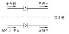
먼저, 도 2에 도시한 것과 같이, 배터리(10)로부터 제공되는 제1 상시전원과 릴레이(20)의 후단에서 제공되는 제2 상시전원은 상호 공통의 공급라인을 통해 컨트롤러(100)의 전원부(120)로 제공될 수 있다. 예를 들어, 집적회로 칩의 형태로 구현되는 컨트롤러에 구비된 하나의 전원 입력 단자에 제1 상시전원과 제2 상시전원이 함께 제공되는 형태로 구현될 수 있다. 이러한 상시전원 공급 형태는 컨트롤러를 제작하는데 있어 하나의 전원 단자만 마련하면 되므로 회로를 단순화 할 수 있으며 그에 따라 사이즈, 중량, 재료비 등을 절감할 수 있다.2, a first constant power source provided from the
다른 예로, 도 3에 도시한 것과 같이, 배터리(10)로부터 제공되는 배터리(10)로부터 제공되는 제1 상시전원과 릴레이(20)의 후단에서 제공되는 제2 상시전원이 상호 분리되어 별도의 공급라인을 통해 컨트롤러(100)의 전원부(120)로 제공될 수 있다. 도 3의 예의 경우, 집적회로 칩의 형태로 구현되는 컨트롤러를 별도로 마련된 두 개의 전원 입력 단자가 필요하다. 도 3의 예는, 도 2의 예에 비해 컨트롤러 사이즈와 중량이 증대되고 제작 비용이 더 소요될 수 있으나, 릴레이(20) 전단과 후단의 전압차이가 큰 경우에도 강건하게 동작할 수 있는 장점이 있다.3, the first constant power source provided from the
도 2 및 도 3에 도시된 다이오드는 역전류를 차단하기 위한 것이다.The diodes shown in Figs. 2 and 3 are for blocking reverse current.
이와 같이, 본 발명의 일 실시형태는 배터리 관리 시스템을 제어하는 컨트롤러가 두 개의 상시전원을 제공받아 동작하게 된다. 따라서, 릴레이(20)가 오프된 상태에서 배터리(10)의 전압이 사전 설정된 레벨 이하로 방전되어 제1 상시전원으로 컨트롤러(20)가 동작할 수 없는 상태인 경우, 릴레이(20)와 부하의 연결라인에 점프 스타트를 위한 외부 전원이 인가되면, 컨트롤러(100)는 이 외부 전원을 제2 상시전원으로 제공받아 동작할 수 있게 된다. 따라서, 컨트롤러(100)가 외부 전원을 통해 정상적으로 동작할 수 있게 되므로, 차량의 점프 스타트를 가능하게 할 뿐만 아니라 재접속 스위치(30)가 접속되는 경우에 이를 컨트롤러(100)가 인지하여 릴레이(20)를 온 시킬 수 있게 된다.As described above, in the embodiment of the present invention, the controller for controlling the battery management system operates by receiving two constant power sources. Therefore, when the voltage of the
도 4는 본 발명의 다른 실시형태에 따른 차량의 배터리 관리 시스템의 블록 구성도이다.4 is a block diagram of a battery management system of a vehicle according to another embodiment of the present invention.
도 4에 도시된 실시형태는, 제1 상시전원이 재접속 스위치(30)가 접속되는 경우에만 인가되는 실시형태이다. 이를 위해, 재접속 스위치(30)의 일단은 배터리(10)와 릴레이(20) 사이의 연결라인에 연결되고, 재접속 스위치(30)의 타단은 컨트롤러(100)의 웨이크업 입력부(110)와 전원부(120)에 동시에 연결되는 형태로 구현될 수 있다.The embodiment shown in Fig. 4 is an embodiment in which the first constant power source is applied only when the
이 실시형태에서, 릴레이(20)가 오프되고 배터리(100)의 전압이 사전 설정된 레벨 이상인 상태에서 재접속 스위치(30)가 접속되면, 컨트롤러(100)의 웨이크업 입력부(110)는 재접속 스위치(30)를 통해 배터리(10)의 전압을 입력 받아 컨트롤러(100)를 웨이크업 시키고, 전원부(120)는 재접속 스위치(30)가 접속 상태를 유지하는 동안 배터리(10)의 전압을 제1 상시전원으로 제공받아 릴레이 제어부(130)를 동작 시킴으로써 릴레이(20)를 온시킬 수 있게 된다.In this embodiment, when the
이어, 릴레이(20)가 온되고 재접속 스위치(30)의 접속이 차단되면 컨트롤러(100)는 릴레이(20) 후단, 즉 릴레이(20)와 부하의 연결라인으로부터 제2 상시전원을 제공받아 정상적인 동작을 유지할 수 있게 된다.When the
이상에서 설명한 것과 같이, 본 발명의 여러 실시형태에 따른 배터리 관리 시스템은, 컨트롤러가 릴레이 전단 및 릴레이 후단에서 각각의 상시전원을 제공받음으로써 배터리가 과방전 되어 컨트롤러를 작동시킬 수 없는 전압을 갖더라도, 차량의 점프 시동을 위해 릴레이 후단에 연결되는 외부 전원을 통해 컨트롤러가 상시전원을 제공받아 동작할 수 있게 된다.As described above, in the battery management system according to various embodiments of the present invention, even if the controller has the voltage that can not operate the controller due to the overdischarging of the battery by receiving the constant power source at the relay front end and the relay rear end And the controller is always powered by an external power source connected to the rear end of the relay for starting the jump of the vehicle.
이에 따라, 본 발명의 여러 실시형태에 따른 배터리 관리 시스템은, 기본적으로 릴레이 제어를 통해 배터리의 과방전 및 과충전을 방지할 수 있을 뿐만 아니라, 배터리가 과방전 되더라도 외부 전원을 통해 차량이 항시 점프 스타트가 가능하게 함으로써 차량의 상품성을 향상시킬 수 있다.Accordingly, the battery management system according to various embodiments of the present invention can basically prevent over discharge and overcharge of the battery through relay control, and even if the battery is overdischarged, So that the merchantability of the vehicle can be improved.
10: 배터리20: 릴레이
30: 재접속 스위치50: 정션박스
61: 시동키62: 저전압 직류 변환기
63: 저전압 전장100: 컨트롤러
110: 웨이크업 입력부120: 전원부
130: 릴레이 제어부10: Battery 20: Relay
30: reconnect switch 50: junction box
61: starter key 62: low-voltage DC converter
63: Low voltage electric field 100: Controller
110: wake-up input unit 120:
130: Relay controller
Claims (12)
Translated fromKorean상기 배터리와 상기 릴레이의 연결라인에서 제1 상시전원을 제공받고, 상기 릴레이와 상기 부하 사이의 연결라인에서 제2 상시전원을 제공받아 동작하며, 상기 릴레이의 온/오프를 제어하는 컨트롤러; 및
사용자의 조작에 의해 접속 상태가 결정되며, 상기 배터리와 상기 릴레이의 연결라인과 상기 컨트롤러에 양단이 각각 연결되며, 상기 접속 상태에 따라 상기 릴레이의 온/오프를 제어하기 위한 신호를 생성하여 컨트롤러로 제공하는 재접속 스위치;를 포함하며,
상기 제1 상시전원은, 상기 재접속 스위치의 접속상태가 온상태일 때 상기 컨트롤러로 제공되며 상기 재접속 스위치의 접속상태가 오프 상태일 경우에는 상기 컨트롤러로 제공되지 않는 것을 특징으로 하는 차량의 배터리 관리 시스템.A relay electrically connecting and disconnecting power supplied from the battery to the load;
A controller provided with a first constant power source at a connection line between the battery and the relay and a second constant power source at a connection line between the relay and the load, and controlling on / off of the relay; And
A connection state is determined by a user's operation, a connection line between the battery and the relay is connected to both ends of the controller, and a signal for controlling on / off of the relay according to the connection state is generated, And a reconnection switch
Wherein the first constant power source is provided to the controller when the connection state of the reconnection switch is on and is not provided to the controller when the connection state of the reconnection switch is off. .
상기 컨트롤러는 상기 재접속 스위치가 접속되는 경우에 상기 제1 상시전원을 제공받으며, 상기 재접속 스위치가 접속 차단된 경우에는 상기 제2 상시전원을 제공받는 것을 특징으로 하는 차량의 배터리 관리 시스템.The method of claim 8,
Wherein the controller is provided with the first constant power source when the reconnect switch is connected and the second constant power source when the reconnect switch is disconnected.
상기 컨트롤러는 상기 재접속 스위치의 접속 신호 또는 차량의 키입력에 따른 액세서리 온 또는 이그니션 온 신호를 입력 받거나, 상기 릴레이와 상기 부하의 연결 라인에 과전압이 인가된 경우 웨이크업 되는 것을 특징으로 하는 차량의 배터리 관리 시스템.The method of claim 8,
Wherein the controller is configured to receive a connection signal of the reconnection switch or an accessory ON or ignition ON signal corresponding to a key input of the vehicle or to wake up when an overvoltage is applied to the connection line of the relay and the load. Management system.
상기 릴레이가 오프되고 상기 배터리의 전압이 사전 설정된 레벨 이상인 상태에서 상기 재접속 스위치가 접속되면, 상기 재접속 스위치를 통해 상기 배터리의 전압을 입력 받아 웨이크업 된 이후 상기 재접속 스위치가 접속 상태를 유지하는 동안 상기 배터리의 전압을 상기 제1 상시전원으로 제공받아 상기 릴레이를 온시키는 것을 특징으로 하는 차량의 배터리 관리 시스템.11. The system of claim 10,
When the relay is turned off and the voltage of the battery is higher than a predetermined level, when the reconnection switch is connected, the voltage of the battery is received through the reconnection switch, And the relay is turned on by receiving the voltage of the battery as the first constant power source.
상기 릴레이가 온되고 상기 재접속 스위치가 접속 차단 상태가 되면, 상기 제2 상시전원을 제공받아 동작하는 것을 특징으로 하는 차량의 배터리 관리 시스템.
12. The system of claim 11,
Wherein when the relay is turned on and the reconnecting switch is in the disconnected state, the second normal power supply is operated.
Priority Applications (3)
| Application Number | Priority Date | Filing Date | Title |
|---|---|---|---|
| KR1020160087361AKR101866037B1 (en) | 2016-07-11 | 2016-07-11 | Battery management system for vehicle |
| US15/376,575US10263438B2 (en) | 2016-07-11 | 2016-12-12 | Battery management system for vehicle |
| CN201710074269.8ACN107599852B (en) | 2016-07-11 | 2017-02-10 | Battery management system for vehicle |
Applications Claiming Priority (1)
| Application Number | Priority Date | Filing Date | Title |
|---|---|---|---|
| KR1020160087361AKR101866037B1 (en) | 2016-07-11 | 2016-07-11 | Battery management system for vehicle |
Publications (2)
| Publication Number | Publication Date |
|---|---|
| KR20180007024A KR20180007024A (en) | 2018-01-22 |
| KR101866037B1true KR101866037B1 (en) | 2018-06-11 |
Family
ID=60911188
Family Applications (1)
| Application Number | Title | Priority Date | Filing Date |
|---|---|---|---|
| KR1020160087361AActiveKR101866037B1 (en) | 2016-07-11 | 2016-07-11 | Battery management system for vehicle |
Country Status (3)
| Country | Link |
|---|---|
| US (1) | US10263438B2 (en) |
| KR (1) | KR101866037B1 (en) |
| CN (1) | CN107599852B (en) |
Families Citing this family (14)
| Publication number | Priority date | Publication date | Assignee | Title |
|---|---|---|---|---|
| KR20180045954A (en)* | 2016-10-26 | 2018-05-08 | 현대자동차주식회사 | Battery management system and the controlling method thereof |
| CN110118144A (en)* | 2018-02-05 | 2019-08-13 | 杨允仁 | Auxiliary engine device |
| KR102125893B1 (en) | 2018-02-21 | 2020-06-23 | 박종수 | Discharge Vehicle Jump Start System Using Auxiliary Energy Storage Device |
| CN110289648B (en)* | 2018-03-19 | 2023-05-23 | 株洲中车时代电气股份有限公司 | Method and system for controlling storage battery of unmanned rail transit vehicle |
| CN108638868A (en)* | 2018-06-28 | 2018-10-12 | 南京恒天领锐汽车有限公司 | A kind of New Low Voltage power control box |
| KR102672245B1 (en)* | 2018-08-31 | 2024-06-03 | 주식회사 엘지에너지솔루션 | Apparatus for managing communication power source of battery pack |
| KR102656482B1 (en)* | 2018-09-19 | 2024-04-11 | 삼성에스디아이 주식회사 | Battery pack and means of transportation having the battery pack |
| KR102075531B1 (en)* | 2018-11-15 | 2020-02-10 | 현대오트론 주식회사 | Appatus for detecting overvoltage position and operating method thereof |
| DE102019203085A1 (en)* | 2019-03-06 | 2020-09-10 | Vitesco Technologies GmbH | Control device for actuating a load and method for operating such a control device |
| JP2020150629A (en)* | 2019-03-12 | 2020-09-17 | 株式会社竹内製作所 | Dc feeder circuit for work vehicle |
| KR102699015B1 (en)* | 2019-04-26 | 2024-08-26 | 현대자동차주식회사 | System and method for controlling low voltage dc-dc converter for vehicle |
| KR102829334B1 (en)* | 2020-02-13 | 2025-07-04 | 현대자동차주식회사 | Multi-path cooling system and cooling system for eco-friendly vehicle applying the same |
| DE102020205327B4 (en) | 2020-04-28 | 2025-05-08 | Thyssenkrupp Ag | Submarine with a situation-independent power supply for a string battery management system |
| US20240270188A1 (en)* | 2023-02-15 | 2024-08-15 | GM Global Technology Operations LLC | Startup methods in battery-less auxiliary low voltage bus |
Citations (10)
| Publication number | Priority date | Publication date | Assignee | Title |
|---|---|---|---|---|
| KR20010111135A (en)* | 2000-06-08 | 2001-12-17 | 이계안 | Jump system of hybrid electric vehicle |
| US20040066168A1 (en)* | 2002-10-04 | 2004-04-08 | George Terry A. | Jump start and reverse battery protection circuit |
| JP2004203178A (en)* | 2002-12-25 | 2004-07-22 | Murata Mach Ltd | Power supply plant, and method for connecting constant current power supply unit in power supply plant |
| KR20110081098A (en)* | 2010-01-06 | 2011-07-13 | 주식회사 엘지화학 | Battery control device and method |
| US20110288705A1 (en)* | 2010-05-20 | 2011-11-24 | Yuichi Kawasaki | Starting control device of electric vehicle |
| JP2012152003A (en)* | 2011-01-19 | 2012-08-09 | Toyota Motor Corp | Power supply device for vehicle |
| KR20130078099A (en)* | 2011-12-30 | 2013-07-10 | 주식회사 효성 | Energy efficiency electric vehicle charge apparatus |
| KR101315645B1 (en)* | 2013-04-17 | 2013-10-08 | 세방전지(주) | Dual battery control system and method thereof |
| JP2015173589A (en)* | 2014-03-04 | 2015-10-01 | ローベルト ボッシュ ゲゼルシャフト ミット ベシュレンクテル ハフツング | Method for implementing jump start procedure or emergency charging procedure of vehicle |
| US20160082854A1 (en)* | 2008-01-03 | 2016-03-24 | F.D. Richardson Enterprises, Inc. Dba Richardson Jumpstarters | Method and apparatus for providing supplemental power to an engine |
Family Cites Families (11)
| Publication number | Priority date | Publication date | Assignee | Title |
|---|---|---|---|---|
| JP3346910B2 (en)* | 1994-10-03 | 2002-11-18 | 本田技研工業株式会社 | Power supply for electric vehicles |
| JP3245334B2 (en)* | 1995-08-03 | 2002-01-15 | 本田技研工業株式会社 | Power control device for electric vehicle |
| JP3336826B2 (en)* | 1995-09-29 | 2002-10-21 | 株式会社デンソー | Anti-theft device |
| WO2002076794A2 (en)* | 2001-03-08 | 2002-10-03 | Siemens Vdo Automotive Corporation | Wake up system for electronic component in a vehicle using a bus technology |
| WO2004071814A1 (en)* | 2003-02-17 | 2004-08-26 | Denso Corporation | Vehicle-use supply system |
| JP4798071B2 (en) | 2007-06-13 | 2011-10-19 | マツダ株式会社 | Automatic engine stop device |
| KR101765934B1 (en)* | 2011-06-10 | 2017-08-08 | 현대자동차주식회사 | Vehicle Starting Apparatus and Control Method thereof |
| JP5974946B2 (en) | 2013-03-21 | 2016-08-23 | 株式会社オートネットワーク技術研究所 | Power supply |
| US9694769B2 (en)* | 2013-06-21 | 2017-07-04 | GM Global Technology Operations LLC | Smart power distribution unit |
| US20150202977A1 (en)* | 2014-01-22 | 2015-07-23 | Michael Rutledge McCall | Vehicle-charged supplemental power system |
| US20150357864A1 (en)* | 2014-06-06 | 2015-12-10 | Bayer Healthcare Llc | Power source switching apparatus and methods for dual-powered electronic devices |
- 2016
- 2016-07-11KRKR1020160087361Apatent/KR101866037B1/enactiveActive
- 2016-12-12USUS15/376,575patent/US10263438B2/enactiveActive
- 2017
- 2017-02-10CNCN201710074269.8Apatent/CN107599852B/enactiveActive
Patent Citations (10)
| Publication number | Priority date | Publication date | Assignee | Title |
|---|---|---|---|---|
| KR20010111135A (en)* | 2000-06-08 | 2001-12-17 | 이계안 | Jump system of hybrid electric vehicle |
| US20040066168A1 (en)* | 2002-10-04 | 2004-04-08 | George Terry A. | Jump start and reverse battery protection circuit |
| JP2004203178A (en)* | 2002-12-25 | 2004-07-22 | Murata Mach Ltd | Power supply plant, and method for connecting constant current power supply unit in power supply plant |
| US20160082854A1 (en)* | 2008-01-03 | 2016-03-24 | F.D. Richardson Enterprises, Inc. Dba Richardson Jumpstarters | Method and apparatus for providing supplemental power to an engine |
| KR20110081098A (en)* | 2010-01-06 | 2011-07-13 | 주식회사 엘지화학 | Battery control device and method |
| US20110288705A1 (en)* | 2010-05-20 | 2011-11-24 | Yuichi Kawasaki | Starting control device of electric vehicle |
| JP2012152003A (en)* | 2011-01-19 | 2012-08-09 | Toyota Motor Corp | Power supply device for vehicle |
| KR20130078099A (en)* | 2011-12-30 | 2013-07-10 | 주식회사 효성 | Energy efficiency electric vehicle charge apparatus |
| KR101315645B1 (en)* | 2013-04-17 | 2013-10-08 | 세방전지(주) | Dual battery control system and method thereof |
| JP2015173589A (en)* | 2014-03-04 | 2015-10-01 | ローベルト ボッシュ ゲゼルシャフト ミット ベシュレンクテル ハフツング | Method for implementing jump start procedure or emergency charging procedure of vehicle |
Also Published As
| Publication number | Publication date |
|---|---|
| CN107599852A (en) | 2018-01-19 |
| KR20180007024A (en) | 2018-01-22 |
| CN107599852B (en) | 2022-03-15 |
| US20180013297A1 (en) | 2018-01-11 |
| US10263438B2 (en) | 2019-04-16 |
Similar Documents
| Publication | Publication Date | Title |
|---|---|---|
| KR101866037B1 (en) | Battery management system for vehicle | |
| KR101846680B1 (en) | Battery management system for vehicle | |
| KR20180045954A (en) | Battery management system and the controlling method thereof | |
| US10160325B2 (en) | Vehicle power control method and system for jump-start | |
| US9174547B2 (en) | Electric vehicle and charging control method for auxiliary battery thereof | |
| US9387763B2 (en) | Power source device for vehicle | |
| US8519563B2 (en) | Electrical system for a motor vehicle and method for control of a starter motor and a battery isolator in such an electrical system | |
| CN109906169B (en) | Operating method for a dual-voltage battery | |
| KR20120062956A (en) | High voltage system of electric vehicles | |
| JP2014030281A (en) | Power-supply system | |
| US20130026823A1 (en) | Battery system for micro-hybrid vehicles comprising high-efficiency consumers | |
| KR101897352B1 (en) | System for processing fault information of vehicle | |
| KR102024196B1 (en) | Electricity storage system | |
| KR101786347B1 (en) | Vehicle electric power system for jump start | |
| US10293703B2 (en) | Method for controlling a voltage source for charging a battery of a motor vehicle | |
| KR20180038822A (en) | System for controlling relay of an auxiliary battery and method thereof | |
| US8237305B2 (en) | Auxiliary electrical power system for vehicular fuel economy improvement | |
| KR20170067186A (en) | System of managing power for vehicle | |
| KR101918361B1 (en) | Battery management system for vehicle | |
| US10266062B2 (en) | System and method for charging a vehicle battery by controlling a relay between the battery and a vehicle system | |
| JP5250953B2 (en) | Power storage circuit | |
| JP2017188972A (en) | Jump starter, and charging method of jump starter | |
| US20160276850A1 (en) | Charging Bus |
Legal Events
| Date | Code | Title | Description |
|---|---|---|---|
| A201 | Request for examination | ||
| PA0109 | Patent application | Patent event code:PA01091R01D Comment text:Patent Application Patent event date:20160711 | |
| PA0201 | Request for examination | ||
| E902 | Notification of reason for refusal | ||
| PE0902 | Notice of grounds for rejection | Comment text:Notification of reason for refusal Patent event date:20171129 Patent event code:PE09021S01D | |
| PG1501 | Laying open of application | ||
| E701 | Decision to grant or registration of patent right | ||
| PE0701 | Decision of registration | Patent event code:PE07011S01D Comment text:Decision to Grant Registration Patent event date:20180418 | |
| PR0701 | Registration of establishment | Comment text:Registration of Establishment Patent event date:20180601 Patent event code:PR07011E01D | |
| PR1002 | Payment of registration fee | Payment date:20180601 End annual number:3 Start annual number:1 | |
| PG1601 | Publication of registration | ||
| PR1001 | Payment of annual fee | Payment date:20210527 Start annual number:4 End annual number:4 | |
| PR1001 | Payment of annual fee | Payment date:20220527 Start annual number:5 End annual number:7 | |
| PR1001 | Payment of annual fee | Payment date:20250526 Start annual number:8 End annual number:8 |