KR101865784B1 - Laser and handpiece to beak down fat in body - Google Patents
Laser and handpiece to beak down fat in bodyDownload PDFInfo
- Publication number
- KR101865784B1 KR101865784B1KR1020170114365AKR20170114365AKR101865784B1KR 101865784 B1KR101865784 B1KR 101865784B1KR 1020170114365 AKR1020170114365 AKR 1020170114365AKR 20170114365 AKR20170114365 AKR 20170114365AKR 101865784 B1KR101865784 B1KR 101865784B1
- Authority
- KR
- South Korea
- Prior art keywords
- diffuser
- laser
- handpiece
- hole
- light
- Prior art date
- Legal status (The legal status is an assumption and is not a legal conclusion. Google has not performed a legal analysis and makes no representation as to the accuracy of the status listed.)
- Active
Links
Images


Classifications
- A—HUMAN NECESSITIES
- A61—MEDICAL OR VETERINARY SCIENCE; HYGIENE
- A61N—ELECTROTHERAPY; MAGNETOTHERAPY; RADIATION THERAPY; ULTRASOUND THERAPY
- A61N5/00—Radiation therapy
- A61N5/06—Radiation therapy using light
- A61N5/0613—Apparatus adapted for a specific treatment
- A61N5/0616—Skin treatment other than tanning
- A—HUMAN NECESSITIES
- A61—MEDICAL OR VETERINARY SCIENCE; HYGIENE
- A61B—DIAGNOSIS; SURGERY; IDENTIFICATION
- A61B18/00—Surgical instruments, devices or methods for transferring non-mechanical forms of energy to or from the body
- A61B18/18—Surgical instruments, devices or methods for transferring non-mechanical forms of energy to or from the body by applying electromagnetic radiation, e.g. microwaves
- A61B18/20—Surgical instruments, devices or methods for transferring non-mechanical forms of energy to or from the body by applying electromagnetic radiation, e.g. microwaves using laser
- A61B18/203—Surgical instruments, devices or methods for transferring non-mechanical forms of energy to or from the body by applying electromagnetic radiation, e.g. microwaves using laser applying laser energy to the outside of the body
- A—HUMAN NECESSITIES
- A61—MEDICAL OR VETERINARY SCIENCE; HYGIENE
- A61N—ELECTROTHERAPY; MAGNETOTHERAPY; RADIATION THERAPY; ULTRASOUND THERAPY
- A61N5/00—Radiation therapy
- A61N5/06—Radiation therapy using light
- A61N5/067—Radiation therapy using light using laser light
- A—HUMAN NECESSITIES
- A61—MEDICAL OR VETERINARY SCIENCE; HYGIENE
- A61B—DIAGNOSIS; SURGERY; IDENTIFICATION
- A61B18/00—Surgical instruments, devices or methods for transferring non-mechanical forms of energy to or from the body
- A61B2018/00315—Surgical instruments, devices or methods for transferring non-mechanical forms of energy to or from the body for treatment of particular body parts
- A61B2018/00452—Skin
- A61B2018/00458—Deeper parts of the skin, e.g. treatment of vascular disorders or port wine stains
- A61B2018/00464—Subcutaneous fat, e.g. liposuction, lipolysis
- A—HUMAN NECESSITIES
- A61—MEDICAL OR VETERINARY SCIENCE; HYGIENE
- A61N—ELECTROTHERAPY; MAGNETOTHERAPY; RADIATION THERAPY; ULTRASOUND THERAPY
- A61N5/00—Radiation therapy
- A61N2005/002—Cooling systems
- A61N2005/005—Cooling systems for cooling the radiator
- A—HUMAN NECESSITIES
- A61—MEDICAL OR VETERINARY SCIENCE; HYGIENE
- A61N—ELECTROTHERAPY; MAGNETOTHERAPY; RADIATION THERAPY; ULTRASOUND THERAPY
- A61N5/00—Radiation therapy
- A61N5/06—Radiation therapy using light
- A61N2005/0664—Details
- A61N2005/0665—Reflectors
- A61N2005/067—
Landscapes
- Health & Medical Sciences (AREA)
- Life Sciences & Earth Sciences (AREA)
- Engineering & Computer Science (AREA)
- Biomedical Technology (AREA)
- Physics & Mathematics (AREA)
- Veterinary Medicine (AREA)
- Optics & Photonics (AREA)
- Nuclear Medicine, Radiotherapy & Molecular Imaging (AREA)
- Animal Behavior & Ethology (AREA)
- General Health & Medical Sciences (AREA)
- Public Health (AREA)
- Surgery (AREA)
- Pathology (AREA)
- Radiology & Medical Imaging (AREA)
- Biophysics (AREA)
- Electromagnetism (AREA)
- Otolaryngology (AREA)
- Heart & Thoracic Surgery (AREA)
- Medical Informatics (AREA)
- Molecular Biology (AREA)
- Radiation-Therapy Devices (AREA)
- Laser Surgery Devices (AREA)
Abstract
Translated fromKoreanDescription
Translated fromKorean본 발명은 레이저를 핸드피스에서 안정적으로 장착함은 물론, 레이저광을 균일하게 산란시켜서 비교적 넓은 범위의 광 조사를 가능하게 하며, 레이저의 발열을 효과적으로 냉각시켜서 레이저가 안정적으로 구동할 수 있게 하는 지방분해용 핸드피스의 레이저 장치와 이를 이용한 핸드피스에 관한 것이다.The present invention can stably mount a laser on a handpiece, and can uniformly scatter laser light to enable a relatively wide range of light irradiation, effectively cooling the heat of the laser, And a handpiece using the same.
일반적으로, 저출력 레이저광 발진장치는 5mW 내지 10mW 범위의 출력과 635nm 내지 650nm정도의 파장을 갖는 레이저광을 방출하는 레이저 다이오드와, 상기 레이저 다이오드로부터 방출되는 레이저광의 빔량을 조절하는 저출력 레이저 다이오드 구동드라이버로 구성된다.Generally, a low-power laser light oscillator is composed of a laser diode that emits laser light having an output in the range of 5 mW to 10 mW and a wavelength of about 635 nm to 650 nm, and a low-power laser diode driver .
이러한 저출력 레이저광을 이용해서 인체의 피하지방 분해는 물론, 경혈이나 환부 등에 질병을 치료하는 효과를 거둘 수 있으며, 종래에는 이러한 각종 의료장비가 개발 및 활용되고 있다.Such low-power laser light can be used to treat subcutaneous fat decomposition in the human body, as well as to treat diseases such as acupuncture and reac- tions. Conventionally, various medical devices have been developed and utilized.
상기 의료장비들의 예를 든다면 저출력 레이저 다이오드의 균일빔을 구현하는 전기매트와, 신체의 허리부위에 착용하는 벨트에 레이저 다이오드를 내설하여 580-980nm 파장의 레이저광을 발생시켜 신체 요추부에 대하여 자극을 가하는 벨트(실용신안등록 제20-0270882호)와, 경혈조사는 물론 만성 관절류마티스, 오십견, 요통, 경추연좌, 통풍, 염좌, 타박, 관절염, 스트레스성 위염 등으로도 그 치료 범위를 넓힌 치료용 레이저/엘이디 포단(실용신안등록제20-0274266호) 등이 있다.Examples of the medical devices include an electric mat that implements a uniform beam of a low power laser diode and a laser diode that is placed on a belt to be worn on the waist of the body to generate a laser beam having a wavelength of 580-980 nm to stimulate the body lumbar (Patent Registration No. 20-0270882), and a treatment for widening the therapeutic range not only of menstrual irregularity but also chronic rheumatoid arthritis, osteoporosis, back pain, cervical vertebra, gout, sprains, bruises, arthritis, And a laser / LED indicator (utility model registration system 20-0274266).
이외에도 종래에는 지방 분해 및 기타 인체 치료 등을 목적으로 다양한 레이저 의료장비가 개발되었고, 이들 중에 대부분은 레이저광이 방출되는 단말 부분인 핸드피스와, 레이저광을 방출시키고 그 동작을 제어하는 컨트롤러로 구성됐다.In addition, various laser medical devices have been developed for the purpose of lipolysis and other human body treatments. Most of them are composed of a handpiece, which is a terminal part where laser light is emitted, and a controller for emitting laser light and controlling its operation done.
그런데 대부분의 종래 레이저 의료장비는 사용자가 핸드피스를 직접 손으로 쥐고 치료 위치 등에 접근시키는 방식이므로, 상기 핸드피스를 소형화 및 경량화해서 사용상의 노동 부담을 줄일 수 있어야 했고, 동작 과정에서 핸드피스가 가열되는 것을 방지해야 했다. 따라서 종래 레이저 의료장비는 레이저가 핸드피스가 아닌 컨트롤러에 설치되었다.However, since most of the conventional laser medical equipment is a method in which the user grasps the handpiece directly by hand and approaches the treatment position, the handpiece must be made compact and lightweight so as to reduce labor burden in use. . Thus, conventional laser medical equipment was installed in the controller, not the laser handpiece.
하지만 이러한 종래 레이저 의료장비는 컨트롤러로부터 레이저가 방출되어 핸드피스에 전달되는 동작 구조를 이루므로, 컨트롤러 1개와 핸드피스 1개가 한 쌍을 이룰 수밖에 없는 한계가 있었다. 더욱이 치료 효과를 높이기 위해서 컨트롤러 1개에 다수 개의 핸드피스를 설치할 경우에는 컨트롤러의 레이저로부터 방출된 레이저광이 핸드피스에 분할되어야 하므로, 비교적 정밀하고 복잡한 분할장치가 요구되었다.However, such a conventional laser medical device has an operation structure in which a laser is emitted from a controller to be transmitted to a handpiece, so that there is a limit in which one controller and one handpiece can not form a pair. Further, when a plurality of handpieces are installed in one controller to increase the therapeutic effect, the laser light emitted from the laser of the controller must be divided into handpieces, so that a relatively precise and complicated division device is required.
이러한 문제를 해소하기 위해 핸드피스에 레이저를 직접 장착하는 기술이 제안되었다.In order to solve this problem, a technique of directly attaching a laser to a handpiece has been proposed.
그러나 핸드피스에 레이저를 장착한 종래 기술은 점 단위의 소면적에 레이저광을 조사하는 펜 사이즈에 한정되므로, 상기 레이저는 상대적으로 소출력 규격이면 충분했다. 물론, 이러한 종래 기술은 레이저 자체의 발열량이 사용자가 쥐고 사용하는데 불편함이 없는 정도이므로, 별도의 추가 장비 없이도 핸드피스에 레이저를 장착하여 사용할 수 있었다.However, since the prior art in which a laser is mounted on a handpiece is limited to a pen size for irradiating a laser beam with a small area on a dot-by-point basis, it is sufficient that the laser has a relatively small output standard. Of course, such a conventional technique is not inconvenient for the user to grasp the calorific value of the laser itself, so that the laser can be mounted on the handpiece without any additional equipment.
하지만, 비교적 넓은 면적에 레이저광을 조사하는 핸드피스의 경우에는 상대적으로 큰 출력의 레이저광을 생성해서 방출시켜야 하므로, 핸드피스 자체가 가열되어 사용가 손으로 직접 쥐고 사용할 수 없었다.However, in the case of the handpiece which irradiates the laser light over a relatively large area, the laser light of a relatively large output has to be generated and emitted, so that the handpiece itself is heated and can not be hand held and used.
결국, 넓은 면적에 대한 레이저광 조사방식의 종래 레이저 의료장비는 레이저의 냉각 기능을 별도로 보강할 수 있는 컨트롤러에 레이저를 설치할 수밖에 없는 한계가 있었다.As a result, conventional laser medical equipment with a large area of laser irradiation has a limitation in installing a laser in a controller capable of separately reinforcing the cooling function of the laser.
이에 본 발명은 상기의 문제를 해소하기 위해 발명된 것으로서, 비교적 넓은 면적에 레이저광을 조사하도록 설계된 핸드피스에 레이저를 장착해서 피부의 넓은 면적에 대한 지방분해와 치료 등을 가능하게 하고, 레이저를 장착하면서도 핸드피스의 경량화와 발열량 감소를 실현하는 지방분해용 핸드피스의 레이저 장치와 이를 이용한 핸드피스의 제공을 해결하고자 하는 과제로 한다.Accordingly, the present invention has been made to solve the above problems, and it is an object of the present invention to provide a handpiece designed to irradiate a laser beam with a relatively large area, And to provide a laser device for a fat splitting handpiece and a handpiece using the laser device, which realizes light weight of the handpiece and reduction of the calorific power while mounting the handpiece.
상기의 과제를 달성하기 위하여 본 발명은,According to an aspect of the present invention,
투광홀이 형성된 서포트와, 냉각수의 출입을 위한 유입홀과 유출홀을 갖는 중공을 이루고 상기 서포트에 형성되는 스탠드를 갖춘 랙;A rack having a support formed with a light-transmitting hole, a stand formed in the support and hollowed with an inlet hole and an outlet hole for the cooling water to enter and exit;
상기 투광홀을 덮도록 상기 서포트에 안착되는 디퓨저;A diffuser mounted on the support so as to cover the light-transmitting hole;
상기 디퓨저에 레이저광을 조사하도록 배치되며, 상기 스탠드와 접촉하게 고정되는 레이저; 및A laser arranged to irradiate the diffuser with a laser beam, the laser being fixed in contact with the stand; And
상기 디퓨저를 투광하는 레이저광이 측방으로 산광하지 않도록 상기 디퓨저의 측면을 감싸 지지하면서 상기 랙에 고정되는 디퓨저 브래킷;A diffuser bracket fixed to the rack while surrounding the side surface of the diffuser so that laser light for projecting the diffuser is not scattered laterally;
을 포함하는 지방분해용 핸드피스의 레이저 장치이다.The laser device of the present invention is a laser device for a fat splitting handpiece.
상기의 다른 기술적 과제를 달성하기 위하여 본 발명은,According to another aspect of the present invention,
개방용 홀이 중앙부위에 형성되고, 냉각수의 출입을 위한 유입구와 유출구를 갖는 수로가 구성된 프레임; 상기 프레임에 안착해서 상기 개방용 홀과 중공이 연통하도록 고정되는 뿔대형 관 타입의 리플렉터;가 구비된 조광용 드럼,A frame having an opening hole formed at a central portion thereof and having a water channel having an inlet port and an outlet port for entering and exiting the cooling water; And a horn large-tube type reflector which is seated on the frame and is fixed so that the opening hole and the hollow communicate with each other,
상기 리플렉터의 중공과 연통하는 투광홀이 형성되고 상기 리플렉터에 안착해 고정되는 서포트와, 냉각수의 출입을 위한 유입홀과 유출홀을 갖는 중공을 이루고 상기 서포트에 형성되는 스탠드를 갖춘 랙; 상기 투광홀을 덮도록 상기 서포트에 안착되는 디퓨저; 상기 디퓨저에 레이저광을 조사하도록 배치되며, 상기 스탠드와 접촉하게 고정되는 레이저; 상기 디퓨저를 투광하는 레이저광이 측방으로 산광하지 않도록 상기 디퓨저의 측면을 감싸 지지하면서 상기 랙에 고정되는 디퓨저 브래킷;이 구비된 레이저 장치.A support having a light transmitting hole communicating with the hollow of the reflector and seated and fixed to the reflector; a rack having a hollow formed in the support, the hollow having an inlet hole and an outlet hole for the cooling water to enter and exit; A diffuser mounted on the support so as to cover the light-transmitting hole; A laser arranged to irradiate the diffuser with a laser beam, the laser being fixed in contact with the stand; And a diffuser bracket fixed to the rack while the side surface of the diffuser is wrapped so that a laser beam for projecting the diffuser is not scattered laterally.
를 포함하는 지방분해용 핸드피스이다.Of the handpiece.
상기의 본 발명은, 비교적 넓은 면적에 레이저광을 조사하도록 설계된 핸드피스에 레이저를 장착해서 피부의 넓은 면적에 대한 지방분해와 치료 등을 가능하게 하고, 레이저를 장착하면서도 핸드피스의 경량화와 발열량 감소를 실현하는 효과가 있다.The present invention is based on the discovery that a laser is mounted on a handpiece designed to irradiate a laser beam over a relatively large area to enable fat decomposition and treatment against a large area of the skin and to reduce the weight of the handpiece and heat generation There is an effect of realizing.
도 1은 본 발명에 따른 지방분해장치의 본체와 핸드피스를 보인 이미지이고,
도 2는 본 발명에 따른 지방분해장치에 구성된 핸드피스의 외관 모습을 보인 이미지이고,
도 3은 상기 핸드피스에서 피부와 접하는 부분의 모습을 보인 이미지이고,
도 4는 상기 핸드피스의 하우징 내부의 외관 모습을 보인 이미지이고,
도 5는 본 발명에 따른 조광용 드럼의 단면 모습을 보인 이미지이고,
도 6은 본 발명에 따른 레이저 장치를 분해 도시한 사시도이고,
도 7은 본 발명에 따른 레이저 장치의 측단면 모습을 도시한 단면도이고,
도 8은 본 발명에 따른 랙의 중공에 냉각수가 충전된 모습을 도시한 단면도이고,
도 9는 본 발명에 따른 조광용 드럼과 레이저 장치의 결합 모습을 도시한 측면도이고,
도 10은 본 발명에 따른 레이저 장치의 다른 실시의 측단면 모습을 도시한 단면도이다.1 is an image showing a main body and a handpiece of the fat decomposition apparatus according to the present invention,
FIG. 2 is an image showing an appearance of a handpiece constructed in the fat decomposition apparatus according to the present invention,
FIG. 3 is an image showing a part of the handpiece contacting the skin,
FIG. 4 is an image showing the appearance of the inside of the housing of the handpiece,
5 is an image showing a cross-sectional view of a light-extracting drum according to the present invention,
FIG. 6 is a perspective view explaining a laser device according to the present invention,
7 is a cross-sectional view showing a side cross-sectional view of the laser device according to the present invention,
8 is a cross-sectional view showing a state where cooling water is filled in the hollow of the rack according to the present invention,
FIG. 9 is a side view showing a combination of a light-extracting drum and a laser device according to the present invention,
10 is a cross-sectional view showing a side cross-sectional view of another embodiment of the laser device according to the present invention.
상술한 본 발명의 특징 및 효과는 첨부된 도면과 관련한 다음의 상세한 설명을 통하여 분명해질 것이며, 그에 따라 본 발명이 속하는 기술분야에서 통상의 지식을 가진 자가 본 발명의 기술적 사상을 용이하게 실시할 수 있을 것이다. 본 발명은 다양한 변경을 가할 수 있고 여러 가지 형태를 가질 수 있는바, 특정 실시 예들을 도면에 예시하고 본문에 상세하게 설명하고자 한다. 그러나 이는 본 발명을 특정한 개시형태에 대해 한정하려는 것이 아니며, 본 발명의 사상 및 기술 범위에 포함되는 모든 변경, 균등물 내지 대체물을 포함하는 것으로 이해되어야 한다. 본 출원에서 사용한 용어는 단지 특정한 실시 예들을 설명하기 위해 사용된 것으로, 본 발명을 한정하려는 의도가 아니다.BRIEF DESCRIPTION OF THE DRAWINGS The above and other features and advantages of the present invention will become more apparent from the following detailed description of the present invention when taken in conjunction with the accompanying drawings, There will be. The present invention is capable of various modifications and various forms, and specific embodiments are illustrated in the drawings and described in detail in the text. It is to be understood, however, that the invention is not intended to be limited to the particular forms disclosed, but on the contrary, is intended to cover all modifications, equivalents, and alternatives falling within the spirit and scope of the invention. The terminology used herein is for the purpose of describing particular embodiments only and is not intended to be limiting of the invention.
이하, 본 발명을 구체적인 내용이 첨부된 도면에 의거하여 상세히 설명한다.Hereinafter, the present invention will be described in detail with reference to the accompanying drawings.
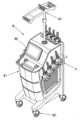
도 1은 본 발명에 따른 지방분해장치의 본체와 핸드피스를 보인 이미지이고, 도 2는 본 발명에 따른 지방분해장치에 구성된 핸드피스의 외관 모습을 보인 이미지이고, 도 3은 상기 핸드피스에서 피부와 접하는 부분의 모습을 보인 이미지이다.FIG. 1 is an image showing a main body and a handpiece of the fat decomposition apparatus according to the present invention, FIG. 2 is an image showing an appearance of a handpiece constructed in the fat decomposition apparatus according to the present invention, And the image of the portion in contact with the image.
본 실시의 지방분해장치(M)는 케이스(M1)와, 지방분해장치(M)의 입출력을 위한 입출력장치(M2)와, 케이스(M1)에 내설되어서 지방분해장치(M)와 핸드피스(H)의 구동을 제어하고 그 상태 등을 확인하기 위한 컨트롤러(미도시)와, 상기 컨트롤러의 제어에 따라 레이저광을 조사하는 하나 이상의 핸드피스(H)를 구성한다.The lipolysis apparatus M according to the present embodiment includes a case M1, an input / output device M2 for inputting / outputting the lipolysis device M, a lipolysis device M and a handpiece (Not shown) for controlling the driving of the main body H and confirming the state thereof, and at least one handpiece H for irradiating the laser light under the control of the controller.
지방분해장치(M)의 입출력장치(M2)는 하나의 스크린에서 입출력을 모두 가능하게 한 터치스크린 기술이 실시될 수 있고, 상기 컨트롤러의 제어에 따라 입출력장치(M2)가 입력값 수집과 출력값 프로세스를 모두 수행한다. 결국, 사용자는 입출력장치(M2)에서 출력된 정보를 바탕으로 후속 실행을 위한 명령을 선택해 입력하고, 입출력장치(M2)는 상기 명령에 대한 입력값을 실행시켜서 상기 컨트롤러에 전달하며, 상기 컨트롤러는 상기 입력값에 따라 해당 프로세스를 실행해서 해당 핸드피스(H)와 입출력장치(M2)를 실행시킨다.The input / output device M2 of the fat decomposition apparatus M may be implemented with a touch screen technology capable of both inputting and outputting from one screen. In accordance with the control of the controller, the input / . As a result, the user selects and inputs a command for subsequent execution based on the information output from the input / output device M2, and the input / output device M2 executes the input value for the command and transmits the command to the controller. And executes the corresponding process according to the input value to execute the handpiece H and the input / output device M2.
한편, 본 실시의 지방분해장치(M)는 케이스(M1)의 원활한 이동을 위한 롤러(M3)를 케이스(M1)의 하단에 구성할 수 있고, 케이스(M1)와 케이블을 매개로 연결된 핸드피스(H)를 걸기 위한 행거(M4)를 케이스(M1)의 상단에 구성할 수 있다.On the other hand, the lipolysis apparatus M of the present embodiment can form the roller M3 for smooth movement of the case M1 at the lower end of the case M1, The hanger M4 for hanging the hook H can be formed at the upper end of the case M1.
참고로 행거(M4)는 비교적 긴 길이의 상기 케이블이 바닥에 늘어져 위치하지 않도록 보관하며, 따라서 핸드피스(H)를 케이스(M1)로부터 원거리에 위치한 사용자에게도 활용할 수 있다.For reference, the hanger M4 stores the cable of a comparatively long length so that it is not positioned on the floor, so that the handpiece H can be utilized for a user located remotely from the case M1.
계속해서 도 1의 'A'에서 보인 핸드피스(H)는 하우징(H1)이 도 2 및 도 3에서 보인 대로 사용자의 피부와 맞닿는 하단의 폭이 상단의 폭에 비해 상대적으로 넓은 형상를 이룬다. 따라서 하우징(H1)의 하단은 피부와 맞닿고, 상단은 케이블과 연결되어서 지방분해장치(M)의 본체로부터 제어신호와 전력과 냉각수를 공급받는다. 본 실시의 하우징(H1)은 피부와 직접 접하는 하단면이 레이저광의 투광을 개방용 홀(111)을 구성하고, 개방용 홀(111)은 피부에 대한 레이저광의 직접 조사를 방지하도록 코팅된 윈도우(W)가 설치될 수 있다.2 and 3, the width of the lower end of the housing H1 contacting the user's skin is relatively large compared to the width of the upper end of the handpiece H shown in FIG. Therefore, the lower end of the housing H1 is in contact with the skin, and the upper end of the housing H1 is connected to the cable so that the control signal, the electric power and the cooling water are supplied from the main body of the fat- The housing H1 of this embodiment constitutes the
참고로, 본 실시의 핸드피스(H)의 하우징(H1)은 핸드피스(H)의 동작 여부를 사용자가 인지할 수 있도록 하나 이상의 램프(H2)를 구성하며, 출력램프(H2)는 컨트롤러에 의해 제어된다. 또한, 하우징(H1)의 하단면은 피부와의 접촉 여부를 감지하는 하나 이상의 센서(112)가 구성되는데, 센서(112)는 상기 하단면이 피부와 접촉했는지 여부를 파악해서 미접촉시에는 램프(H2)를 통해 사용자에게 경고하고, 더 나아가 컨트롤러는 센서(112)로부터 받은 신호에 따라 구동에 대한 진행 여부를 판단한다.The housing H1 of the handpiece H of the present embodiment constitutes one or more lamps H2 so that the user can recognize whether the handpiece H is operated and the output lamp H2 is connected to the controller . The lower end of the housing H1 is configured to detect whether or not the lower end of the housing H1 contacts the skin. The
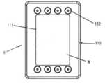
도 4는 상기 핸드피스의 하우징 내부의 외관 모습을 보인 이미지이고, 도 5는 본 발명에 따른 조광용 드럼의 단면 모습을 보인 이미지이다.FIG. 4 is an image showing the appearance of the inside of the housing of the handpiece, and FIG. 5 is an image showing a sectional view of the drum for illuminating according to the present invention.
본 실시의 핸드피스(H)는, 개방용 홀(111)이 중앙부위에 형성되고, 냉각수의 출입을 위한 유입구(114)와 유출구(114')를 갖는 수로(113)가 구성된 프레임(110); 프레임(110)에 안착해서 개방용 홀(111)과 중공이 연통하도록 고정되는 뿔대형 관 타입의 리플렉터(120);가 구비된 조광용 드럼(100)과 함께, 레이저 장치(200)를 포함한다.The handpiece H of the present embodiment has a
우선 조광용 드럼(100)을 설명하면, 조광용 드럼(100)은 레이저 장치(200)로부터 조사된 레이저광을 개방용 홀(111) 방향으로 집광해서 피부에 조사하도록 가이드하는 것으로, 프레임(110)과 리플렉터(120)로 구성된다.The
프레임(110)은 레이저광의 원활한 조사를 위한 개방용 홀(111)을 구성하며, 개방용 홀(111)에는 투명성 윈도우(W)가 설치된다. 본 실시에서 프레임(110)은 4각의 링 형상이며, 윈도우(W)는 개방용 홀(111)의 내측으로 돌출된 플랜지에 걸쳐진 구조로 결합된다.The
계속해서, 프레임(110)은 사용자의 피부와 직접 맞닿으며 자체 냉각을 위한 수로(113)를 구성한다. 여기서 수로(113)는 프레임(110)을 따라 형성되며, 냉각수의 출입을 위한 유입구(114)와 유출구(114')를 갖는다. 따라서 유입구(114)로 유입된 냉각수는 수로를 따라 이동하면서 프레임(110)의 열기를 식히고, 수압에 의해서 유출구(114')로 배출된다. 결국, 피부와 직접 맞닿는 프레임(110)은 자체 냉각을 통해서 사용자가 열기로 인한 불편을 해소시킨다.Subsequently, the
리플렉터(120)는 프레임(110)과의 연결부가 상대적으로 넓은 단면적을 이루는 뿔대 형상이며, 레이저 장치(200)로부터 조사되어 산광하는 레이저광이 유출됨이 없이 개방용 홀(111)을 통해 피부에 조사되도록 가이드한다. 이를 위해 리플렉터(120)는 뿔대 형상의 반사관(121)을 구성한다. 여기서 반사관(121)의 내면은 반사도가 우수한 재질로 코팅되면, 따라서 레이저 장치(200)에서 조사된 레이저광은 손실 없이 개방용 홀(111)을 통해 방출된다.The
계속해서 반사관(121)의 하단 둘레에는 가압 플랜지(122)가 형성된다. 가압 플랜지(122)는 프레임(110)과의 물리적 결합을 위한 구성이며, 프레임(110)과 볼트, 핀, 접착제 등의 결합수단을 매개로 고정된다. 참고로 수로(113)의 유입구(114) 및 유출구(114')와 각각 연결되는 호스(미도시)와, 센서(112)와 연결되는 전선(112a)의 인출을 위해서 상기 호스와 전선은 가압 플랜지(122)를 관통할 수 있다.Subsequently, a pressurizing
한편, 리플렉터(120)와 프레임(110) 간에 누광 없는 긴밀한 결합을 위해서, 리플렉터(120)의 가압 플랜지(122)와 프레임(110) 사이에 마감재(115)를 구성한다. 반사관(121)은 도 5에서와 같이 윈도우(W)를 가압하도록 연장하게 형성될 수 있고, 마감재(115)는 프레임(110)과 연장부 사이에도 배치될 수도 있다.A finishing
이하에서는 레이저 장치(200)의 구성을 도면을 참고해서 좀 더 상세하게 설명한다.Hereinafter, the configuration of the
도 6은 본 발명에 따른 레이저 장치를 분해 도시한 사시도이고, 도 7은 본 발명에 따른 레이저 장치의 측단면 모습을 도시한 단면도이다.FIG. 6 is a perspective view showing an exploded view of the laser device according to the present invention, and FIG. 7 is a sectional view showing a side sectional view of the laser device according to the present invention.
본 실시의 레이저 장치(200)는 리플렉터(120)의 중공과 연통하는 투광홀(211a)이 형성되고 리플렉터(120)에 안착해 고정되는 서포트(211)와, 냉각수의 출입을 위한 유입홀(212a)과 유출홀(212b)을 갖는 중공(212a)을 이루고 서포트(211)에 형성되는 스탠드(212)를 갖춘 랙(210); 투광홀(211a)을 덮도록 상기 서포트(211)에 안착되는 디퓨저(220); 디퓨저(220)에 레이저광을 조사하도록 배치되며, 스탠드(212)와 접촉하게 고정되는 레이저(230); 디퓨저(220)를 투광하는 레이저광이 측방으로 산광하지 않도록 디퓨저(220)의 측면을 감싸 지지하면서 랙(212)에 고정되는 디퓨저 브래킷(240);이 구비된다.The
본 실시의 랙(210)은 디퓨저(220)를 안착하고 레이저(230)를 지지하기 위한 브래킷의 일종으로, 디퓨저(220)를 안착하는 서포트(211)는 디퓨저(220)에서 산광한 레이저광이 조광용 드럼(100)으로 조사되도록 투광홀(211a)을 형성한다. 따라서 디퓨저(220)는 투광홀(211a)을 덮도록 배치된다.The
한편, 본 실시의 스탠드(212)는 서포트(211)의 일측에 구성되며, 레이저(230)의 발열을 냉각시키기 위한 중공(212a)을 구성한다. 중공(212a)은 냉각수가 충전되어서 스탠드(212)에 밀착한 레이저(230)를 냉각시키며, 냉각수의 순환을 위한 유입홀(212a)과 유출홀(212b)을 구성한다.On the other hand, the
또한, 본 실시의 스탠드(212)는 디퓨저(220)의 측단의 삽입을 위한 고정홈(212d)을 형성한다. 디퓨저(220)와 랙(210) 간에 결합 방식은 다양할 수 있는데, 본 실시는 디퓨저(220)의 일측을 수용하는 고정홈(212d)을 스탠드(212)의 일면에 형성시켜서 디퓨저(220)가 긴밀히 맞물려 결합할 수 있게 한다.The
디퓨저(220)는 프리즘과 같이 빛을 산광하는 재질로 구성되며, 본 실시의 디퓨저(220)는 레이저광의 효과적인 산광을 위해서 저면이 오목한 형상을 이루는 것이 바람직하다. 디퓨저(220)는 수광한 레이저의 반사를 최소화하기 위해 AR코팅( Anti Reflection Coating)을 할 수 있고, 디퓨저(220)의 재질과 종류는 다양할 수 있다.The
레이저(230)는 스탠드(212)에 밀착하게 설치되며, 방출하는 레이저광이 디퓨저(220)를 통해 투광홀(211a)로 투광하도록 조사한다. 레이저(230)의 구동을 위한 전력은 본체와 연결되는 케이블을 통해 전달되며, 레이저(230)의 제어 또한 본체의 컨트롤러를 통해 이루어진다.The
디퓨저 브래킷(240)은 디퓨저(220)의 둘레를 감싸서 디퓨저(220)로부터 레이저광이 주변으로 방출되는 것을 차단한다. 또한 디퓨저 브래킷(240)은 디퓨저(220)의 일측이 고정홈(212d)에 압입되도록 가압한다. 결국, 본 실시의 핸드피스(H)를 사용자가 이용해도 디퓨저(220)는 랙(210)과 안정된 결합 상태를 유지할 수 있다.The
계속해서 디퓨저 브래킷(240)은, 디퓨저(220)를 사이에 두고 스탠드(212)와 마주하게 배치되는 중앙부(241)와, 중앙부(241)의 양측단으로부터 각각 연장 형성되어서 랙(210)에 고정되는 한 쌍의 단부(242)로 구성된다. 이때, 한 쌍의 단부(242)에는 각각 랙(210)과의 결속을 위한 고정홀(243)이 형성될 수 있다. 결국, 디퓨저 브래킷(240)이 디퓨저(220)의 일측을 스탠드(212)의 고정홈(212d)에 압입하기 위해서는 디퓨저 브래킷(240)의 중앙부(241)가 디퓨저(220)와 밀착한다. 참고로, 단부(242)에 형성된 고정홈(243)은 디퓨저(220)의 압입 강도를 조절할 수 있도록 장축의 구멍을 이룬다. 따라서 랙(210)에 대한 디퓨저 브래킷(240)의 설치 위치를 조정할 수 있고, 이를 통해 디퓨저 브래킷(240)에 의해 고정되는 디퓨저(220)의 사이즈를 조정할 수 있다.Subsequently, the
도 8은 본 발명에 따른 랙의 중공에 냉각수가 충전된 모습을 도시한 단면도이고, 도 9는 본 발명에 따른 조광용 드럼과 레이저 장치의 결합 모습을 도시한 측면도이다.FIG. 8 is a sectional view showing a state where cooling water is filled in the hollow of a rack according to the present invention, and FIG. 9 is a side view showing a combination of a light-extracting drum and a laser device according to the present invention.
전술한 바와 같이, 레이저(230)의 냉각을 위해서 스탠드(212)는 냉각수(CW)를 수용하기 위한 중공(212a)을 구성하고, 중공(212a)은 냉각수(CW)의 유출입을 위한 유입홀(212b)과 유출홀(212c)을 구성한다. 이때, 유입홀(212b)과 유출홀(212c)에는 각각 호스와의 연결을 위한 어댑터(P1, P2)가 설치된다.As described above, in order to cool the
본 실시의 유입홀(212b)은 중공(212a)의 하단에 배치되고, 유출홀(212c)은 중공(212c)의 상단에 배치된다. 따라서 외부로부터 중공(212a)으로 유입되는 냉각수는 중공(212a)의 하단에 배치된 유입홀(212b)을 따라 중공(212a)에 유입되므로, 냉각수(CW)가 중공(212a)에 완전히 충전되기 전까지는 유출홀(212c)을 통해 외부로 배수되지 않는다. 즉, 냉각수(CW)는 중공(212a)에 항상 충전되어서 레이저(230)를 항시 냉각시킬 수 있다.The
본 실시의 냉각수(CW) 순환은 도 9에서 보인 대로 본체로부터 프레임(110)의 수로(113)에 우선 공급되고 수로(113)로부터 배출된 냉각수(CW)는 랙(210)의 중공(212a)으로 유입되어서 프레임(110)과 레이저(230)를 모두 냉각시키며, 이는 피부와 접촉하는 부분을 우선적으로 냉각시키기 위함이다.The circulation of the cooling water CW of this embodiment is first supplied to the
도 10은 본 발명에 따른 레이저 장치의 다른 실시의 측단면 모습을 도시한 단면도이다.10 is a cross-sectional view showing a side cross-sectional view of another embodiment of the laser device according to the present invention.
본 실시의 디퓨저 브래킷(240)은, 중앙부(241)의 상방으로 연장 형성되는 커버(244)로 구성되되; 중앙부(241)와 커버(244)의 경계 부위(245)가 디퓨저(220)와 밀착하여 가압하도록 돌출하게 형성되어서, 고정홈(212d)에 삽입된 디퓨저(220)의 일측이 압입된다.The
이를 좀 더 구체적으로 설명하면, 레이저(230)로부터 조사된 레이저광은 디퓨저(220)를 투광하면서 산광하고, 이 과정에서 산광되는 레이저광이 투광홀(211a) 외에 타방으로도 방출될 수 있다. 따라서 디퓨저(220)의 측면은 디퓨저 브래킷(240)에 의해 차단되지만 레이저(230) 방향으로 방출되는 레이저광까지는 완전히 차단될 수 없다. 이러한 문제를 해결하기 위해서 디퓨저 브래킷(240)은 상방으로 연장하여 형성된 커버(244)를 포함한다.More specifically, the laser beam irradiated from the
커버(244)는 레이저(230)와 디퓨저(220) 사이의 공간을 덮어서, 상기 공간으로 누광되는 레이저광을 차단한다. 본 실시에서는 중앙부(241)에만 커버(244)가 구성된 것으로 했으나, 단부(242)에도 상방으로 연장 형성된 커버(244)가 구성되어서 레이저(230)와 디퓨저(220) 사이의 둘레가 커버(244)에 의해 모두 덮히도록 할 수 있다.The
한편, 디퓨저 브래킷(240)의 중앙부(241)로부터 연장된 커버(244)는 중앙부(241)와의 경계 부위(245)가 디퓨저(220)의 상부 코너 부분과 접하도록 돌출되어서, 중앙부(241)와 양측 단부(242) 모두가 디퓨저(220)의 측면과 밀착하지 않아도 상기 경계 부위(245)의 가압만으로 디퓨저(220)를 고정홈(212d)에 압입할 수 있다.The
참고로, 중앙부(241)는 스탠드(212)의 고정홈(212d)과 마주하므로, 경계 부위(245)에 의한 가압은 디퓨저(220)를 고정홈(212d)으로 삽입한다.The
결국 디퓨저 브래킷(240)과의 강제 접촉에 의한 디퓨저(220)의 훼손을 최소화할 수 있고, 보다 안정된 결합 구조를 완성한다.As a result, damage to the
앞서 설명한 본 발명의 상세한 설명에서는 본 발명의 바람직한 실시 예들을 참조해 설명했지만, 해당 기술분야의 숙련된 당업자 또는 해당 기술분야에 통상의 지식을 갖는 자라면 후술될 특허청구범위에 기재된 본 발명의 사상 및 기술영역으로부터 벗어나지 않는 범위 내에서 본 발명을 다양하게 수정 및 변경시킬 수 있음을 이해할 수 있을 것이다.While the present invention has been described in connection with what is presently considered to be practical exemplary embodiments, it is to be understood that the invention is not limited to the disclosed embodiments, but, on the contrary, It will be understood by those skilled in the art that various changes in form and details may be made therein without departing from the spirit and scope of the invention as defined by the appended claims.
100; 조광용 드럼110; 프레임111; 개방용 홀
112; 센서113; 수로114; 유입구
114'; 유출구115; 마감재120; 리플랙터
121; 반사관122; 가압플랜지200; 레이저 장치
210; 랙211; 서포트212; 스탠드
220; 디퓨저230; 레이저240; 디퓨저 브래킷
241; 중앙부242; 단부243; 고정홀
244; 커버245; 경계 부위100; A
112;
114 '; An
121;
210;
220;
241; A
244;
Claims (8)
Translated fromKorean상기 투광홀을 덮도록 상기 서포트에 안착되는 디퓨저;
상기 디퓨저에 레이저광을 조사하도록 배치되며, 상기 스탠드와 접촉하게 고정되는 레이저; 및
상기 디퓨저를 투광하는 레이저광이 측방으로 산광하지 않도록 상기 디퓨저의 측면을 감싸 지지하면서 상기 랙에 고정되는 디퓨저 브래킷;
을 포함하는 것을 특징으로 하는 지방분해용 핸드피스의 레이저 장치.A rack having a support formed with a light-transmitting hole, a stand formed in the support and hollowed with an inlet hole and an outlet hole for the cooling water to enter and exit;
A diffuser mounted on the support so as to cover the light-transmitting hole;
A laser arranged to irradiate the diffuser with a laser beam, the laser being fixed in contact with the stand; And
A diffuser bracket fixed to the rack while surrounding the side surface of the diffuser so that laser light for projecting the diffuser is not scattered laterally;
And a laser device for processing the fat.
상기 스탠드는 상기 디퓨저의 측단의 삽입을 위한 고정홈을 형성하고, 상기 디퓨저 브래킷은 상기 디퓨저의 일측이 상기 고정홈에 압입되도록 가압하는 것;
을 특징으로 하는 지방분해용 핸드피스의 레이저 장치.The method according to claim 1,
Wherein the stand forms a fixing groove for insertion of a side end of the diffuser, the diffuser bracket presses one side of the diffuser so as to press the fixing groove into the fixing groove;
And a laser device for fat splitting.
상기 투광홀과 마주하는 디퓨저의 저면은 오목한 형상인 것;
을 특징으로 하는 지방분해용 핸드피스의 레이저 장치.The method according to claim 1,
The bottom surface of the diffuser facing the light-transmitting hole is concave;
And a laser device for fat splitting.
상기 유입홀은 상기 중공의 하단에 배치되고, 상기 유출홀은 상기 중공의 상단에 배치되는 것;
을 특징으로 하는 지방분해용 핸드피스의 레이저 장치.The method according to claim 1,
The inflow hole is disposed at the lower end of the hollow, and the outflow hole is disposed at the upper end of the hollow;
And a laser device for fat splitting.
상기 디퓨저를 사이에 두고 상기 스탠드와 마주하게 배치되는 중앙부와, 상기 중앙부의 양측단으로부터 각각 연장 형성되어서 상기 랙에 고정되는 한 쌍의 단부와, 상기 중앙부의 상방으로 연장 형성되는 커버로 구성되되;
상기 중앙부와 커버의 경계 부위가 상기 디퓨저와 밀착하여 가압하도록 돌출하게 형성되어서, 상기 고정홈에 삽입된 상기 디퓨저의 일측이 압입된 것;을 특징으로 하는 지방분해용 핸드피스의 레이저 장치.3. The apparatus of claim 2, wherein the diffuser bracket
A pair of end portions extending from both side ends of the center portion to be fixed to the rack, and a cover extending upward from the center portion;
Wherein a boundary portion between the center portion and the cover is formed so as to be in close contact with the diffuser so as to be pressed so that one side of the diffuser inserted in the fixing groove is press-fitted.
상기 리플렉터의 중공과 연통하는 투광홀이 형성되고 상기 리플렉터에 안착해 고정되는 서포트와, 냉각수의 출입을 위한 유입홀과 유출홀을 갖는 중공을 이루고 상기 서포트에 형성되는 스탠드를 갖춘 랙; 상기 투광홀을 덮도록 상기 서포트에 안착되는 디퓨저; 상기 디퓨저에 레이저광을 조사하도록 배치되며, 상기 스탠드와 접촉하게 고정되는 레이저; 상기 디퓨저를 투광하는 레이저광이 측방으로 산광하지 않도록 상기 디퓨저의 측면을 감싸 지지하면서 상기 랙에 고정되는 디퓨저 브래킷;이 구비된 레이저 장치.
를 포함하는 것을 특징으로 하는 지방분해용 핸드피스.A frame having an opening hole formed at a central portion thereof and having a water channel having an inlet port and an outlet port for entering and exiting the cooling water; And a horn large-tube type reflector which is seated on the frame and is fixed so that the opening hole and the hollow communicate with each other,
A support having a light transmitting hole communicating with the hollow of the reflector and seated and fixed to the reflector; a rack having a hollow formed in the support, the hollow having an inlet hole and an outlet hole for the cooling water to enter and exit; A diffuser mounted on the support so as to cover the light-transmitting hole; A laser arranged to irradiate the diffuser with a laser beam, the laser being fixed in contact with the stand; And a diffuser bracket fixed to the rack while the side surface of the diffuser is wrapped so that a laser beam for projecting the diffuser is not scattered laterally.
Characterized in that the handpiece comprises a handpiece.
상기 수로의 냉각수가 상기 스탠드의 중공으로 유입되도록, 상기 유출구와 유입홀이 연통하는 것;
을 특징으로 하는 지방분해용 핸드피스.The method according to claim 6,
The outlet communicating with the inlet hole such that the cooling water of the channel is introduced into the hollow of the stand;
Characterized in that the handpiece is a handpiece.
피부와 접하는 상기 프레임의 일면을 따라 피부와의 접촉 여부를 감시하는 하나 또는 둘 이상의 센서가 구성된 것;
을 특징으로 하는 지방분해용 핸드피스.
The method according to claim 6,
One or more sensors configured to monitor contact with the skin along one side of the frame in contact with the skin;
Characterized in that the handpiece is a handpiece.
Priority Applications (2)
| Application Number | Priority Date | Filing Date | Title |
|---|---|---|---|
| KR1020170114365AKR101865784B1 (en) | 2017-09-07 | 2017-09-07 | Laser and handpiece to beak down fat in body |
| PCT/KR2018/010454WO2019050312A1 (en) | 2017-09-07 | 2018-09-07 | Lipolysis handpiece laser device and handpiece using same |
Applications Claiming Priority (1)
| Application Number | Priority Date | Filing Date | Title |
|---|---|---|---|
| KR1020170114365AKR101865784B1 (en) | 2017-09-07 | 2017-09-07 | Laser and handpiece to beak down fat in body |
Publications (1)
| Publication Number | Publication Date |
|---|---|
| KR101865784B1true KR101865784B1 (en) | 2018-06-08 |
Family
ID=62600388
Family Applications (1)
| Application Number | Title | Priority Date | Filing Date |
|---|---|---|---|
| KR1020170114365AActiveKR101865784B1 (en) | 2017-09-07 | 2017-09-07 | Laser and handpiece to beak down fat in body |
Country Status (2)
| Country | Link |
|---|---|
| KR (1) | KR101865784B1 (en) |
| WO (1) | WO2019050312A1 (en) |
Cited By (4)
| Publication number | Priority date | Publication date | Assignee | Title |
|---|---|---|---|---|
| CN108837330A (en)* | 2018-06-27 | 2018-11-20 | 武汉洛芙科技股份有限公司 | Laser fiber double chin weight reducing apparatus with refrigeration |
| WO2019050312A1 (en)* | 2017-09-07 | 2019-03-14 | 주식회사 지티지웰니스 | Lipolysis handpiece laser device and handpiece using same |
| KR20200080517A (en)* | 2018-12-27 | 2020-07-07 | 주식회사 루트로닉 | A treatment apparatus |
| WO2023243577A1 (en)* | 2022-06-13 | 2023-12-21 | 帝人ファーマ株式会社 | Phototherapy apparatus |
Citations (3)
| Publication number | Priority date | Publication date | Assignee | Title |
|---|---|---|---|---|
| KR20140085267A (en)* | 2012-12-27 | 2014-07-07 | 주식회사 메디스코 | Hand piece for intensive pulse light illuminating with reflector having the plural curvature |
| KR101688424B1 (en)* | 2016-05-30 | 2017-01-02 | 정성재 | Ultrasonic cartridge and head of ultrasonic therapy system for treatment |
| KR101814109B1 (en)* | 2016-07-04 | 2018-01-02 | 주식회사 파나시 | Multifunction apparatus for skin treatment |
Family Cites Families (4)
| Publication number | Priority date | Publication date | Assignee | Title |
|---|---|---|---|---|
| US5735844A (en)* | 1995-02-01 | 1998-04-07 | The General Hospital Corporation | Hair removal using optical pulses |
| JPH08266649A (en)* | 1995-03-31 | 1996-10-15 | Toshiba Medical Eng Co Ltd | Laser therapy equipment |
| KR101232708B1 (en)* | 2010-07-20 | 2013-02-13 | (주)클래시스 | Handpiece for skin care device having cooling funtion |
| KR101865784B1 (en)* | 2017-09-07 | 2018-06-08 | 주식회사 지티지웰니스 | Laser and handpiece to beak down fat in body |
- 2017
- 2017-09-07KRKR1020170114365Apatent/KR101865784B1/enactiveActive
- 2018
- 2018-09-07WOPCT/KR2018/010454patent/WO2019050312A1/ennot_activeCeased
Patent Citations (3)
| Publication number | Priority date | Publication date | Assignee | Title |
|---|---|---|---|---|
| KR20140085267A (en)* | 2012-12-27 | 2014-07-07 | 주식회사 메디스코 | Hand piece for intensive pulse light illuminating with reflector having the plural curvature |
| KR101688424B1 (en)* | 2016-05-30 | 2017-01-02 | 정성재 | Ultrasonic cartridge and head of ultrasonic therapy system for treatment |
| KR101814109B1 (en)* | 2016-07-04 | 2018-01-02 | 주식회사 파나시 | Multifunction apparatus for skin treatment |
Cited By (5)
| Publication number | Priority date | Publication date | Assignee | Title |
|---|---|---|---|---|
| WO2019050312A1 (en)* | 2017-09-07 | 2019-03-14 | 주식회사 지티지웰니스 | Lipolysis handpiece laser device and handpiece using same |
| CN108837330A (en)* | 2018-06-27 | 2018-11-20 | 武汉洛芙科技股份有限公司 | Laser fiber double chin weight reducing apparatus with refrigeration |
| KR20200080517A (en)* | 2018-12-27 | 2020-07-07 | 주식회사 루트로닉 | A treatment apparatus |
| KR102192616B1 (en) | 2018-12-27 | 2020-12-17 | 주식회사 루트로닉 | A light radiation apparatus |
| WO2023243577A1 (en)* | 2022-06-13 | 2023-12-21 | 帝人ファーマ株式会社 | Phototherapy apparatus |
Also Published As
| Publication number | Publication date |
|---|---|
| WO2019050312A1 (en) | 2019-03-14 |
Similar Documents
| Publication | Publication Date | Title |
|---|---|---|
| KR101865784B1 (en) | Laser and handpiece to beak down fat in body | |
| EP2051774B1 (en) | System of plaster and radiation device | |
| US9561385B2 (en) | Light therapy platform system | |
| US20060217787A1 (en) | Light therapy device | |
| US9724536B1 (en) | Embedded fiber phototherapy light cap | |
| KR101803868B1 (en) | Skin care apparatus for hand | |
| US20190126061A1 (en) | Treatment device for scalp | |
| KR101788725B1 (en) | Noninvasive laser pain reliever | |
| AU2022336837A1 (en) | Phototherapy mask | |
| KR20210001284A (en) | rhinitis therapeutic device | |
| KR101906514B1 (en) | Laser apparatus for skin treatment | |
| CN108635678B (en) | Light guide structure, light emitting device, therapeutic instrument, beauty mask and comprehensive treatment system | |
| KR102409046B1 (en) | Portable lighting device for vulva and anal | |
| KR101412497B1 (en) | apparatus for skin massage. | |
| KR102146759B1 (en) | Multi-purpose portable light treatment device | |
| KR101631921B1 (en) | a coupling structure of the thermotherapy device | |
| KR102785829B1 (en) | Pet care device | |
| CN210057152U (en) | Light guide structure, light emitting device, therapeutic apparatus, beauty mask and comprehensive treatment system | |
| US20230149078A1 (en) | Improved cooling for a personal care device | |
| KR101875409B1 (en) | Head wearable type apparatus | |
| KR20180040948A (en) | Skin stick-type patch using diffusion optical fiber | |
| KR101944999B1 (en) | Laser apparatus for skin treatment | |
| EP1813307A1 (en) | Phototherapy light with fresnel lens for infant care apparatus | |
| KR101878914B1 (en) | Massage apparatus | |
| KR200245818Y1 (en) | laser appliance for medical freatment |
Legal Events
| Date | Code | Title | Description |
|---|---|---|---|
| PA0109 | Patent application | Patent event code:PA01091R01D Comment text:Patent Application Patent event date:20170907 | |
| PA0201 | Request for examination | ||
| PA0302 | Request for accelerated examination | Patent event date:20180305 Patent event code:PA03022R01D Comment text:Request for Accelerated Examination Patent event date:20170907 Patent event code:PA03021R01I Comment text:Patent Application | |
| E701 | Decision to grant or registration of patent right | ||
| PE0701 | Decision of registration | Patent event code:PE07011S01D Comment text:Decision to Grant Registration Patent event date:20180419 | |
| GRNT | Written decision to grant | ||
| PR0701 | Registration of establishment | Comment text:Registration of Establishment Patent event date:20180601 Patent event code:PR07011E01D | |
| PR1002 | Payment of registration fee | Payment date:20180601 End annual number:3 Start annual number:1 | |
| PG1601 | Publication of registration | ||
| PR1001 | Payment of annual fee | Payment date:20210407 Start annual number:4 End annual number:4 | |
| PR1001 | Payment of annual fee | Payment date:20230508 Start annual number:6 End annual number:6 | |
| PR1001 | Payment of annual fee | Payment date:20250526 Start annual number:8 End annual number:8 |