KR101862404B1 - Apparatus and method for eliminating noise of stereo image - Google Patents
Apparatus and method for eliminating noise of stereo imageDownload PDFInfo
- Publication number
- KR101862404B1 KR101862404B1KR1020110131659AKR20110131659AKR101862404B1KR 101862404 B1KR101862404 B1KR 101862404B1KR 1020110131659 AKR1020110131659 AKR 1020110131659AKR 20110131659 AKR20110131659 AKR 20110131659AKR 101862404 B1KR101862404 B1KR 101862404B1
- Authority
- KR
- South Korea
- Prior art keywords
- sensor unit
- image
- pixel difference
- image acquired
- corrected
- Prior art date
- Legal status (The legal status is an assumption and is not a legal conclusion. Google has not performed a legal analysis and makes no representation as to the accuracy of the status listed.)
- Active
Links
Images


Classifications
- H—ELECTRICITY
- H04—ELECTRIC COMMUNICATION TECHNIQUE
- H04N—PICTORIAL COMMUNICATION, e.g. TELEVISION
- H04N13/00—Stereoscopic video systems; Multi-view video systems; Details thereof
- H04N13/10—Processing, recording or transmission of stereoscopic or multi-view image signals
- H04N13/106—Processing image signals
- H04N13/128—Adjusting depth or disparity
- H—ELECTRICITY
- H04—ELECTRIC COMMUNICATION TECHNIQUE
- H04N—PICTORIAL COMMUNICATION, e.g. TELEVISION
- H04N13/00—Stereoscopic video systems; Multi-view video systems; Details thereof
- H04N13/20—Image signal generators
- H04N13/204—Image signal generators using stereoscopic image cameras
- H04N13/246—Calibration of cameras
- H—ELECTRICITY
- H04—ELECTRIC COMMUNICATION TECHNIQUE
- H04N—PICTORIAL COMMUNICATION, e.g. TELEVISION
- H04N13/00—Stereoscopic video systems; Multi-view video systems; Details thereof
- H04N13/20—Image signal generators
- H04N13/204—Image signal generators using stereoscopic image cameras
- H04N13/239—Image signal generators using stereoscopic image cameras using two 2D image sensors having a relative position equal to or related to the interocular distance
- H—ELECTRICITY
- H04—ELECTRIC COMMUNICATION TECHNIQUE
- H04N—PICTORIAL COMMUNICATION, e.g. TELEVISION
- H04N2213/00—Details of stereoscopic systems
- H04N2213/003—Aspects relating to the "2D+depth" image format
Landscapes
- Engineering & Computer Science (AREA)
- Multimedia (AREA)
- Signal Processing (AREA)
- Testing, Inspecting, Measuring Of Stereoscopic Televisions And Televisions (AREA)
- Measurement Of Optical Distance (AREA)
- Studio Devices (AREA)
- Length Measuring Devices By Optical Means (AREA)
Abstract
Translated fromKoreanDescription
Translated fromKorean본 발명은 노이즈 제거기술에 관한 것으로서, 보다 상세하게는 스테레오 영상에 발생하는 스트리킹 노이즈를 제거하기 위한 장치 및 방법에 관한 것이다.
BACKGROUND OF THE INVENTION 1. Field of the Invention The present invention relates to a noise reduction technique, and more particularly, to an apparatus and a method for eliminating streaking noise generated in a stereo image.
일반적으로, 스테레오 매칭이란, 좌영상과 우영상(즉, 스테레오 영상)의 각 픽셀(pixel)의 매칭을 통하여 물체가 얼마나 떨어져 있는지를 알아내는 기술이다.Generally, stereo matching is a technique for finding out how far an object is located by matching each pixel of a left image and a right image (i.e., a stereo image).
예를 들어, 손가락 하나를 양 눈 사이에 가까이 위치시키면, 좌안만 뜨는 경우에는 손가락이 오른쪽에 위치하지만, 우안만 뜨는 경우에는 손가락이 왼쪽에 위치한다. 반면, 매우 멀리 있는 산봉우리를 보는 경우에는, 좌안만 떴을 경우 혹은 우안만 떴을 경우 모두 산봉우리가 가운데 위치하고 있을 것이다.For example, if you place one finger between two eyes, your finger will be on the right if you are floating only on your left eye, but your finger will be on the left if you are only on your right eye. On the other hand, if you are looking at a very distant mountain peak, you will find the mountain peak in the middle when you open the left eye or the right eye.
이와 같이, 스테레오 매칭에서는, 스테레오 카메라를 이용하여 영상을 획득하는 경우, 거리에 따라 물체가 카메라에 찍히게 되는 위치가 달라지는데, 이 정보를 이용하여 깊이영상(depth image)를 추출한다.In stereo matching, when a stereo camera is used to acquire an image, a position at which an object is photographed varies depending on the distance, and a depth image is extracted using the information.
스테레오 카메라를 설계함에 있어 중요한 것은, 스테레오 영상을 촬영하는 두 센서를 정렬(alignment)하는 것이다.In designing a stereo camera, it is important to align the two sensors that capture the stereo image.
스테레오 영상을 촬영하는 두 센서간 정렬불량(misalignment)은, 스테레오 영상에서 깊이영상을 추출할 때 스트리킹 노이즈(streaking noise)를 야기하는 문제점이 있다.Misalignment between two sensors for capturing a stereo image has a problem of causing streaking noise when extracting a depth image from a stereo image.
도 1a는 스테레오 영상의 일예이고, 도 1b는 도 1a의 스트레오 영상으로부터 추출한 깊이영상의 일예이다.1A is an example of a stereo image, and FIG. 1B is an example of a depth image extracted from a stereo image of FIG. 1A.
도 1a의 스테레오 영상(좌영상 및 우영상)은 정렬불량 상태의 영상으로서, 우영상이 좌영상에 대해 정렬되지 않아, 도 1b와 같이, 깊이영상에 스트리킹 노이즈가 발생하게 되는 문제점이 있다.The stereo image (left image and right image) of FIG. 1A is an image of a misaligned state, and the right image is not aligned with respect to the left image, and streaking noise is generated in the depth image as shown in FIG.
즉, 종래의 스테레오 시스템에서는, 스테레오 영상을 취득하는 센서간 틸트(tilt) 또는 회전(rotation)에 의해 깊이영상에 스트리킹 노이즈가 발생하여, 영상의 인식률이 저하되는 문제점이 있다.
That is, in the conventional stereo system, streaking noise is generated in the depth image due to tilt or rotation between the sensors for acquiring the stereo image, which lowers the recognition rate of the image.
본 발명은 상기한 바와 같은 문제점을 해결하기 위하여 제안된 것으로, 스테레오 카메라의 센서부에 광학적 손떨림 보정부(OIS)를 적용하여, 스테레오 영상 중 하나의 영상에 대해 다른 영상을 광학적 손떨림 보정부(OIS)를 이용하여 보정함으로써, 스트리킹 노이즈를 최소화하는 스테레오 영상의 노이즈 제거장치 및 방법을 제공하는데 그 목적이 있다.
SUMMARY OF THE INVENTION The present invention has been proposed in order to solve the above-mentioned problems, and an object of the present invention is to provide an optical image stabilizer (OIS) to a sensor part of a stereo camera, The present invention has been made in view of the above problems, and it is an object of the present invention to provide an apparatus and method for removing noise of a stereo image that minimizes streaking noise.
상기와 같은 목적을 달성하기 위해, 제1센서부 및 제2센서부가 획득한 스테레오 영상의 노이즈를 제거하는, 본 발명의 노이즈 제거장치는, 상기 제1센서부가 획득한 영상과 상기 제2센서부가 획득한 영상의 기준픽셀차를 저장하는 저장부; 소정의 기준점을 기준으로, 상기 제1센서부가 획득한 영상에 대한 상기 제2센서부가 획득한 영상의 픽셀차를 연산하여, 상기 기준픽셀차로부터 보정할 픽셀량을 결정하고, 이를 이용하여 광학적 손떨림 방지(OIS) 액추에이터를 구동하는 구동신호를 생성하는 제어부; 및 상기 제어부로부터 수신한 구동신호에 따라 상기 제2센서부가 획득한 영상을 교정하는 상기 OIS 액추에이터를 포함한다.In order to achieve the above object, a noise removing apparatus of the present invention for eliminating the noise of a stereo image acquired by the first sensor unit and the second sensor unit, A storage unit for storing a reference pixel difference of the acquired image; A pixel difference of an image acquired by the second sensor unit with respect to an image acquired by the first sensor unit is calculated on the basis of a predetermined reference point to determine a pixel amount to be corrected from the reference pixel difference, A control unit for generating a drive signal for driving the OIS actuator; And the OIS actuator for calibrating an image acquired by the second sensor unit according to a drive signal received from the control unit.
본 발명의 일실시예에서, 상기 제1센서부가 획득한 영상과 교정된 상기 제2센서부가 획득한 영상을 이용하여 깊이영상을 추출하는 추출부를 더 포함하는 것이 바람직하다.In one embodiment of the present invention, the apparatus further includes an extraction unit for extracting a depth image using the image acquired by the first sensor unit and the image acquired by the second sensor unit.
본 발명의 일실시예에서, 상기 OIS 액추에이터는, 보정할 픽셀량만큼 상기 제2제어부에서 획득되는 영상을 이동하여 교정하는 것이 바람직하다.In an embodiment of the present invention, the OIS actuator preferably moves and corrects an image acquired by the second control unit by a pixel amount to be corrected.
본 발명의 일실시예에서, 상기 제1센서부 및 상기 제2센서부는, 상보형 금속 산화 반도체(CMOS)인 것이 바람직하다.In one embodiment of the present invention, the first sensor unit and the second sensor unit are preferably complementary metal oxide semiconductor (CMOS).
본 발명의 일실시예에서, 상기 기준픽셀차는, 상기 제1센서부 및 상기 제2센서부의 이격거리에 따라 미리 결정되는 것이 바람직하다.
In one embodiment of the present invention, it is preferable that the reference pixel difference is determined in advance according to a separation distance between the first sensor unit and the second sensor unit.
또한, 상기와 같은 목적을 달성하기 위해, 제1센서부 및 제2센서부가 획득한 스테레오 영상의 노이즈를 제거하는 본 발명의 노이즈 제거방법은, 소정의 기준점을 기준으로, 상기 제1센서부가 획득한 영상에 대한 상기 제2센서부가 획득한 영상의 픽셀차를 연산하는 단계; 기준픽셀차와 상기 픽셀차로부터, 상기 제2센서부가 획득한 영상의 보정할 픽셀량을 결정하는 단계; 상기 보정할 픽셀량에 의해 OIS 액추에이터를 구동하기 위한 구동신호를 결정하는 단계를 포함한다.According to another aspect of the present invention, there is provided a noise elimination method for eliminating noise in a stereo image acquired by a first sensor unit and a second sensor unit, Calculating a pixel difference of an image obtained by the second sensor unit with respect to one image; Determining from the reference pixel difference and the pixel difference an amount of pixels to be corrected of the image obtained by the second sensor unit; And determining a drive signal for driving the OIS actuator by the amount of pixels to be corrected.
본 발명의 일실시예에서, 상기 구동신호에 따라 상기 OIS 액추에이터가 상기 제2센서부가 획득한 영상을 교정하는 단계를 더 포함하는 것이 바람직하다.In an embodiment of the present invention, it is preferable that the OIS actuator corrects the image acquired by the second sensor unit according to the driving signal.
본 발명의 일실시예에서, 상기 제1센서부가 획득한 영상과 교정된 상기 제2센서부가 획득한 영상을 이용하여 깊이영상을 추출하는 단계를 더 포함하는 것이 바람직하다.In one embodiment of the present invention, the method further includes extracting a depth image using the image acquired by the first sensor unit and the image acquired by the second sensor unit calibrated.
본 발명의 일실시예에서, 상기 기준픽셀차는, 상기 제1센서부 및 상기 제2센서부의 이격거리에 따라 미리 결정되는 것이 바람직하다.
In one embodiment of the present invention, it is preferable that the reference pixel difference is determined in advance according to a separation distance between the first sensor unit and the second sensor unit.
상기와 같은 본 발명은, 스테레오 영상의 정렬불량을 최소화하여 스트리킹 노이즈를 최소화하도록 하는 효과가 있다.The present invention has the effect of minimizing the streaking noise by minimizing the alignment error of the stereo image.
또한, 본 발명은, 스트리킹 노이즈를 최소화함으로써, 스테레오 영상의 깊이영상을 보다 깨끗하게 추출하도록 하는 효과가 있다.
Further, the present invention has the effect of extracting the depth image of the stereo image more cleanly by minimizing the streaking noise.
도 1a는 스테레오 영상의 일예이다.
도 1b는 도 1a의 스트레오 영상으로부터 추출한 깊이영상의 일예이다.
도 2는 본 발명의 일실시예에 따른 스테레오 영상의 노이즈 제거장치의 일실시예 구성도이다.
도 3a 및 도 3b는 각각 도 2의 제1 및 제2센서부가 획득한 영상의 일예시도이다.
도 4는 본 발명의 일실시예에 따라 교정된 도 3b의 영상을 나타낸다.
도 5는 본 발명의 일실시예에 따른 노이즈 제거방법을 설명하기 위한 흐름도이다.1A is an example of a stereo image.
1B is an example of a depth image extracted from the stereo image of FIG. 1A.
2 is a block diagram of an apparatus for removing noise of a stereo image according to an embodiment of the present invention.
3A and 3B are views illustrating an example of an image acquired by the first and second sensor units of FIG. 2, respectively.
Figure 4 shows the image of Figure 3b calibrated in accordance with an embodiment of the present invention.
5 is a flowchart illustrating a noise removing method according to an embodiment of the present invention.
본 발명은 다양한 변경을 가할 수 있고 여러가지 실시예를 가질 수 있는바, 특정 실시예들을 도면에 예시하고 상세한 설명에 상세하게 설명하고자 한다. 그러나, 이는 본 발명을 특정한 실시 형태에 대해 한정하려는 것이 아니며, 본 발명의 사상 및 기술범위에 포함되는 모든 변경, 균등물 내지 대체물을 포함하는 것으로 이해되어야 한다.While the invention is susceptible to various modifications and alternative forms, specific embodiments thereof are shown by way of example in the drawings and will herein be described in detail. It should be understood, however, that the invention is not intended to be limited to the particular embodiments, but includes all modifications, equivalents, and alternatives falling within the spirit and scope of the invention.
제1, 제2 등과 같이 서수를 포함하는 용어는 다양한 구성요소들을 설명하는데 사용될 수 있지만, 해당 구성요소들은 이와 같은 용어들에 의해 한정되지는 않는다. 이 용어들은 하나의 구성요소들을 다른 구성요소로부터 구별하는 목적으로만 사용된다.Terms including ordinals such as first, second, etc. may be used to describe various elements, but the elements are not limited by such terms. These terms are used only to distinguish one component from another.
어떤 구성요소가 다른 구성요소에 '연결되어' 있다거나, 또는 '접속되어' 있다고 언급된 때에는, 그 다른 구성요소에 직접적으로 연결되어 있거나 또는 접속되어 있을 수도 있지만, 중간에 다른 구성요소가 존재할 수도 있다고 이해되어야 할 것이다. 반면에, 어떤 구성요소가 다른 구성요소에 '직접 연결되어' 있다거나, '직접 접속되어' 있다고 언급된 때에는, 중간에 다른 구성요소가 존재하지 않는 것으로 이해되어야 할 것이다.When an element is referred to as being "connected" or "connected" to another element, it may be directly connected or connected to the other element, but other elements may be present in between . On the other hand, when an element is referred to as being "directly connected" or "directly connected" to another element, it should be understood that there are no other elements in between.
본 출원에서 사용한 용어는 단지 특정한 실시예를 설명하기 위해 사용된 것으로, 본 발명을 한정하려는 의도가 아니다. 단수의 표현은 문맥상 명백하게 다르게 뜻하지 않는 한, 복수의 표현을 포함한다. 본 출원에서, '포함한다' 또는 '가지다' 등의 용어는 명세서상에 기재된 특징, 숫자, 단계, 동작, 구성요소, 부품 또는 이들을 조합한 것이 존재함을 지정하려는 것이지, 하나 또는 그 이상의 다른 특징들이나 숫자, 단계, 동작, 구성요소, 부품 또는 이들을 조합한 것들의 존재 또는 부가 가능성을 미리 배제하지 않는 것으로 이해되어야 한다.The terminology used in this application is used only to describe a specific embodiment and is not intended to limit the invention. The singular expressions include plural expressions unless the context clearly dictates otherwise. In this application, the terms "comprises", "having", and the like are used to specify that a feature, a number, a step, an operation, an element, a component, or a combination thereof, But do not preclude the presence or addition of one or more other features, integers, steps, operations, elements, components, or combinations thereof.
이하, 첨부된 도면을 참조하여 본 발명에 따른 바람직한 일실시예를 상세히 설명한다.Hereinafter, a preferred embodiment of the present invention will be described in detail with reference to the accompanying drawings.
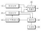
도 2는 본 발명의 일실시예에 따른 스테레오 영상의 노이즈 제거장치의 일실시예 구성도이다.2 is a block diagram of an apparatus for removing noise of a stereo image according to an embodiment of the present invention.
도면에 도시된 바와 같이, 본 발명의 일실시예에 따른 노이즈 제거장치는, 제1센서부(10), 제2센서부(20), 광학적 손떨림 방지(Optical Image Stabilizer; 이하, 'OIS'라 함) 액추에이터(actuator)(30), 제어부(40), 저장부(50) 및 깊이영상 추출부(60)를 포함한다.As shown in the figure, a noise removing apparatus according to an embodiment of the present invention includes a
제1센서부(10)와 제2센서부(20)는 소정 간격을 두고 배치되어, 각각 스테레오 영상 중 하나를 획득한다. 예를 들어, 제1센서부(10)는 좌영상을 획득하고, 제2센서부(20)는 우영상을 획득할 수 있다. 반면, 제1센서부(10)가 우영상을 획득하고, 제2센서부(20)가 좌영상을 획득할 수도 있다. 본 발명의 설명에서는, 설명의 편의상, 제1센서부(10)가 획득하는 영상을 좌영상으로, 제2센서부(20)가 획득하는 영상을 우영상으로 정하여 설명하기로 하겠다.The
또한, 본 발명의 일실시예의 설명에서는 제1센서부(10)에서 획득하는 영상을 기준으로, 제2센서부(20)에서 획득하는 영상의 위치를 변경하도록 영상을 보정하는 것으로 예를 들어 설명하기로 한다. 그러나, 제2센서부(20)에서 획득하는 영상을 기준으로, 제1센서부(10)에서 획득하는 영상의 위치를 변경하도록 영상을 보정하는 것을 배제하는 것은 아님은, 본 발명이 속하는 기술분야에서 통상의 지식을 가진 자에게 있어 자명하다 할 것이다.In the description of the embodiment of the present invention, the image is corrected so as to change the position of the image acquired by the
제1센서부(10)와 제2센서부(20)는 예를 들어, 상보형 금속 산화 반도체(Complementary Metal-Oxide Semiconductor; CMOS)로 구성될 수 있으나, 이에 한정되는 것은 아니다.The
제1센서부(10)와 제2센서부(20)는 소정 거리 이격되는 것으로서, 이격되는 거리는 일정하므로, 제1센서부(10)가 획득한 좌영상과 제2센서부(20)가 획득한 우영상이 소정의 기준점을 중심으로 몇 픽셀 떨어져 있는지(이를 '기준픽셀차'라고 하자)는 미리 결정되어, 저장부(50)에 저장된다. 이때, 기준점은, 예를 들어 영상의 중심점이다.Since the
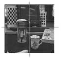
도 3a 및 도 3b는 각각 도 2의 제1 및 제2센서부가 획득한 영상의 일예시도로서, 제1센서부(10)가 좌영상을, 제2센서부(20)가 우영상을 획득하는 경우를 나타낸 것이다.3A and 3B are diagrams illustrating an example of an image obtained by the first and second sensor units of FIG. 2, respectively, in which the
도면에 도시된 바와 같이, 제1센서부(10)의 좌영상의 중심점(A)을 기준으로, 제2센서부(20)가 획득한 우영상은, 원칙적으로는 이격되어 있는 거리(이격거리)에 해당하는 픽셀만큼 그 중심점(B)이 이동하여야 하지만, 정렬불량으로 인해 도 3b와 같이 영상이 틀어져 있다.As shown in the figure, the right image acquired by the
제어부(40)는, 이와 같이 제1센서부(10)가 획득한 좌영상 대비 제2센서부(20)가 획득한 우영상의 픽셀차를 연산하여, 저장부(50)가 저장하고 있는 기준픽셀차로부터 보정할 픽셀량을 결정한다. 또한, 제어부(40)는, 보정할 픽셀량만큼 OIS 액추에이터(30)가 구동하도록 하는 구동신호(예를 들어, 전류신호, 전압신호 등)를 OIS 액추에이터(30)에 전달한다.The
OIS 액추에이터(30)는, 제어부(40)로부터 수신한 구동신호를 수신하여, 보정할 픽셀량만큼 제2센서부(20)에서 획득되는 영상을 이동하여, 영상을 교정(calibration)한다.The
도 4는 본 발명의 일실시예에 따라 교정된 도 3b의 영상을 나타낸다. 도면에 도시된 바와 같이, 본 발명의 OIS 액추에이터(30)에 의해 영상을 교정하여, 정렬불량이 해소되었음을 알 수 있다.Figure 4 shows the image of Figure 3b calibrated in accordance with an embodiment of the present invention. As shown in the figure, the image is corrected by the
깊이영상 추출부(60)는 제1센서부(10)로부터 좌영상을 수신하고, 제2센서부(20)로부터 교정된 우영상을 수신하여, 스테레오 매칭을 위한 깊이영상을 추출한다.The depth
다만, 깊이영상을 추출하는 알고리즘에 대해서는, 본 발명이 속하는 기술분야에서 널리 알려진 바와 같다 할 것이므로, 상세한 설명은 생략하기로 한다.
However, the algorithm for extracting the depth image will be as well known in the art to which the present invention belongs, and a detailed description thereof will be omitted.
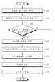
도 5는 본 발명의 일실시예에 따른 노이즈 제거방법을 설명하기 위한 흐름도이다.5 is a flowchart illustrating a noise removing method according to an embodiment of the present invention.
도면에 도시된 바와 같이, 본 발명의 일실시예에 따른 노이즈 제거방법은, 제1센서부(10)와 제2센서부(20)로부터 각각 좌영상 및 우영상을 획득한다(S51). 제1센서부(10)가 좌영상을, 제2센서부(20)가 우영상을 획득하는 것을 예를 들어 설명하겠으나, 이에 한정되지 않음은 이미 설명한 바와 같다.As shown in the figure, a noise removal method according to an embodiment of the present invention acquires left and right images from the
또한, 본 발명의 일실시예에서, 제1센서부(10)가 획득한 좌영상을 기준영상으로 하는 것을 설명하겠으나, 제2센서부(20)가 획득한 우영상을 기준영상으로 하여 제1센서부(10)의 영상을 교정하는 경우도 본 발명의 사상을 구현하는 것임은, 이미 설명한 바와 같다.Although it is described that the left image obtained by the
이후, 제어부(40)는 소정의 기준점에서 기준영상인 좌영상 대비 우영상의 픽셀차를 연산한다(S52). 저장부(50)에는 제1센서부(10)와 제2센서부(20)의 이격거리에 해당하는 기준픽셀차가 저장되어 있다.Thereafter, the
따라서, 제어부(40)는 S52에서 연산한 픽셀차가 기준픽셀차와 동일한지 판단한다(S53). 픽셀차가 기준픽셀차와 동일한 경우에는, 기준영상인 좌영상 대비 우영상이 정확하게 정렬되었다는 것을 의미한다. 이 경우, 깊이영상 추출부(60)는 좌영상과 우영상을 가지고 깊이영상을 추출한다(S58).Therefore, the
만약 S53에서, 픽셀차가 기준픽셀차와 동일하지 않은 경우에는, 기준영상인 좌영상에 대해 우영상이 정렬불량되었다는 것을 의미한다. 이 경우, 제어부(40)는 저장부(50)가 저장하고 있는 기준픽셀차와 S52에서 구한 픽셀차로부터, 보정할 픽셀량을 결정한다(S54).If the pixel difference is not equal to the reference pixel difference in S53, it means that the right image is misaligned with respect to the left image, which is the reference image. In this case, the
또한, 제어부(40)는, 보정할 픽셀량만큼 OIS 액추에이터(30)를 구동하기 위한 구동신호를 결정하여(S55), OIS 액추에이터(30)에 전달한다. 제어부(40)로부터 수신한 구동신호에 의해 OIS 액추에이터(30)가 구동하고(S56), 이에 의해, 제2센서부(20)가 획득하는 우영상을 교정할 수 있다(S57).The
이후, 깊이영상 추출부(60)가 제1센서부(10)가 획득한 좌영상 및 제2센서부(20)가 획득한, 보정된 우영상을 이용하여, 스테레오 영상의 깊이영상을 추출한다(S58).Thereafter, the depth
이와 같은 본 발명에 의하면, 스테레오 영상의 정렬불량을 최소화하여 스트리킹 노이즈를 최소화할 수 있으며, 이를 통해 보다 깨끗한 깊이영상을 추출할 수 있다.
According to the present invention, the streaking noise can be minimized by minimizing the alignment error of the stereo image, and thus, a clean depth image can be extracted.
한편, 본 발명의 실시예들은 컴퓨터로 판독 가능한 기록매체에 컴퓨터가 읽어들일 수 있는 프로그램 코드를 기록하여 구현하는 것이 가능하다. 본 발명의 실시예들이 소프트웨어를 이용하여 실행되는 경우, 본 발명의 구성수단들은 필요한 작업을 실행하는 코드 세그먼트들이다. 또한, 프로그램 또는 코드 세그먼트들은 컴퓨터의 프로세서로 판독 가능한 매체에 저장되거나 전송 매체 또는 통신망을 통해 반송파와 결합된 컴퓨터 데이터 신호로 전송될 수 있다.In the meantime, embodiments of the present invention can be implemented by recording computer-readable program codes on a computer-readable recording medium. When embodiments of the present invention are implemented using software, the constituent means of the present invention are code segments that perform the necessary tasks. The program or code segments may also be stored in a medium readable by a processor of the computer or transmitted in a computer data signal coupled with a carrier wave via a transmission medium or a communication network.
컴퓨터로 판독 가능한 기록매체에는 컴퓨터 시스템이 읽어들일 수 있는 데이터를 저장하는 모든 종류의 기록장치가 포함될 수 있다. 예컨대, 컴퓨터 판독가능 기록매체에는 ROM, RAM, CD-ROM, 자기 테이프, 플로피디스크, 광데이터 저장장치 등이 포함될 수 있다. 또한, 네트워크로 연결된 컴퓨터 시스템에 컴퓨터 판독가능 기록매체를 분산배치하여 컴퓨터가 읽어들일 수 있는 코드가 분산 방식으로 저장되고 실행되도록 할 수 있다.The computer-readable recording medium may include any type of recording device that stores data that can be read by a computer system. For example, the computer-readable recording medium may include ROM, RAM, CD-ROM, magnetic tape, floppy disk, optical data storage, and the like. In addition, the computer readable recording medium may be distributed to the networked computer system so that the computer readable code is stored and executed in a distributed manner.
이상에서 본 발명에 따른 실시예들이 설명되었으나, 이는 예시적인 것에 불과하며, 당해 분야에서 통상적 지식을 가진 자라면 이로부터 다양한 변형 및 균등한 범위의 실시예가 가능하다는 점을 이해할 것이다. 따라서, 본 발명의 진정한 기술적 보호 범위는 다음의 특허청구범위에 의해서 정해져야 할 것이다.
While the invention has been shown and described with reference to certain preferred embodiments thereof, it will be understood by those skilled in the art that various changes and modifications may be made without departing from the spirit and scope of the invention as defined by the appended claims. Accordingly, the true scope of the present invention should be determined by the following claims.
10: 제1센서부20: 제2센서부
30: OIS 액추에이터40: 제어부
50: 저장부60: 깊이영상 추출부10: first sensor unit 20: second sensor unit
30: OIS actuator 40:
50: storage unit 60: depth image extracting unit
Claims (9)
Translated fromKorean상기 제1센서부가 획득한 영상과 상기 제2센서부가 획득한 영상의 기준픽셀차를 저장하는 저장부;
소정의 기준점을 기준으로, 상기 제1센서부가 획득한 영상에 대한 상기 제2센서부가 획득한 영상의 픽셀차를 연산하여, 상기 기준픽셀차로부터 보정할 픽셀량을 결정하고, 이를 이용하여 광학적 손떨림 방지(OIS) 액추에이터를 구동하는 구동신호를 생성하는 제어부; 및
상기 제어부로부터 수신한 구동신호에 따라 상기 제2센서부가 획득한 영상을 교정하는 상기 OIS 액추에이터를 포함하고,
상기 기준픽셀차는 상기 제1센서부가 획득한 영상과 상기 제2센서부가 획득한 영상이 소정의 기준점을 중심으로 몇 픽셀 떨어져 있는지를 나타내며, 상기 기준픽셀차는 상기 제1센서부와 상기 제2센서부의 이격 거리에 따라 미리 결정되고,
상기 제어부는 연산된 상기 픽셀차와 상기 기준픽셀차로부터 보정할 상기 픽셀량을 결정하는 노이즈 제거장치.
An apparatus for eliminating noise in a stereo image acquired by a first sensor unit and a second sensor unit,
A storage unit for storing a reference pixel difference of an image acquired by the first sensor unit and an image acquired by the second sensor unit;
A pixel difference of an image acquired by the second sensor unit with respect to an image acquired by the first sensor unit is calculated on the basis of a predetermined reference point to determine a pixel amount to be corrected from the reference pixel difference, A control unit for generating a drive signal for driving the OIS actuator; And
And the OIS actuator for calibrating an image acquired by the second sensor unit according to a drive signal received from the control unit,
Wherein the reference pixel difference indicates how many pixels the image obtained by the first sensor unit and the image obtained by the second sensor unit are apart from each other about a predetermined reference point and the reference pixel difference is a difference between the first sensor unit and the second sensor unit Is determined in advance according to the separation distance,
Wherein the control unit determines the pixel amount to be corrected from the calculated pixel difference and the reference pixel difference.
The apparatus of claim 1, further comprising an extraction unit extracting a depth image using the image acquired by the first sensor unit and the image captured by the second sensor unit.
The apparatus of claim 1, wherein the OIS actuator moves and calibrates an image acquired by the second sensor unit by a pixel amount to be corrected.
The apparatus of claim 1, wherein the first sensor unit and the second sensor unit are complementary metal oxide semiconductor (CMOS).
2. The noise canceling apparatus according to claim 1, wherein the reference pixel difference is determined in advance according to a separation distance between the first sensor unit and the second sensor unit.
소정의 기준점을 기준으로, 상기 제1센서부가 획득한 영상에 대한 상기 제2센서부가 획득한 영상의 픽셀차를 연산하는 단계;
기준픽셀차와 상기 픽셀차로부터, 상기 제2센서부가 획득한 영상의 보정할 픽셀량을 결정하는 단계;
상기 보정할 픽셀량에 의해 OIS 액추에이터를 구동하기 위한 구동신호를 결정하는 단계를 포함하며,
상기 기준픽셀차는 상기 제1센서부가 획득한 영상과 상기 제2센서부가 획득한 영상이 소정의 기준점을 중심으로 몇 픽셀 떨어져 있는지를 나타내며, 상기 기준픽셀차는 상기 제1센서부와 상기 제2센서부의 이격 거리에 따라 미리 결정되고,
상기 보정할 픽셀량은 연산된 상기 픽셀차와 상기 기준픽셀차로부터 결정되는 노이즈 제거방법.
A method of removing noise of a stereo image acquired by a first sensor unit and a second sensor unit,
Calculating a pixel difference of an image acquired by the second sensor unit with respect to an image acquired by the first sensor unit based on a predetermined reference point;
Determining from the reference pixel difference and the pixel difference an amount of pixels to be corrected of the image obtained by the second sensor unit;
And determining a drive signal for driving the OIS actuator by the amount of pixels to be corrected,
Wherein the reference pixel difference indicates how many pixels the image obtained by the first sensor unit and the image obtained by the second sensor unit are centered around a predetermined reference point, and the reference pixel difference is a difference between the first sensor unit and the second sensor unit Is determined in advance according to the separation distance,
Wherein the pixel amount to be corrected is determined from the calculated pixel difference and the reference pixel difference.
상기 구동신호에 따라 상기 OIS 액추에이터가 상기 제2센서부가 획득한 영상을 교정하는 단계를 더 포함하는 노이즈 제거방법.
The method according to claim 6,
And correcting the image acquired by the OIS actuator by the second sensor unit in accordance with the drive signal.
상기 제1센서부가 획득한 영상과 교정된 상기 제2센서부가 획득한 영상을 이용하여 깊이영상을 추출하는 단계를 더 포함하는 노이즈 제거방법.
8. The method of claim 7,
Further comprising the step of extracting a depth image using the image acquired by the first sensor unit and the image acquired by the second sensor unit calibrated.
상기 제1센서부 및 상기 제2센서부의 이격거리에 따라 미리 결정되는 노이즈 제거방법.
7. The method of claim 6,
Wherein the first sensor unit and the second sensor unit are spaced apart from each other by a distance between the first sensor unit and the second sensor unit.
Priority Applications (4)
| Application Number | Priority Date | Filing Date | Title |
|---|---|---|---|
| KR1020110131659AKR101862404B1 (en) | 2011-12-09 | 2011-12-09 | Apparatus and method for eliminating noise of stereo image |
| US14/360,889US9961322B2 (en) | 2011-12-09 | 2012-11-05 | Apparatus and method for eliminating noise in stereo image |
| PCT/KR2012/009245WO2013085148A1 (en) | 2011-12-09 | 2012-11-05 | Apparatus and method for eliminating noise in stereo image |
| TW101142840ATWI575928B (en) | 2011-12-09 | 2012-11-16 | Apparatus and method for eliminating noise in stereo image |
Applications Claiming Priority (1)
| Application Number | Priority Date | Filing Date | Title |
|---|---|---|---|
| KR1020110131659AKR101862404B1 (en) | 2011-12-09 | 2011-12-09 | Apparatus and method for eliminating noise of stereo image |
Publications (2)
| Publication Number | Publication Date |
|---|---|
| KR20130064999A KR20130064999A (en) | 2013-06-19 |
| KR101862404B1true KR101862404B1 (en) | 2018-05-29 |
Family
ID=48574475
Family Applications (1)
| Application Number | Title | Priority Date | Filing Date |
|---|---|---|---|
| KR1020110131659AActiveKR101862404B1 (en) | 2011-12-09 | 2011-12-09 | Apparatus and method for eliminating noise of stereo image |
Country Status (4)
| Country | Link |
|---|---|
| US (1) | US9961322B2 (en) |
| KR (1) | KR101862404B1 (en) |
| TW (1) | TWI575928B (en) |
| WO (1) | WO2013085148A1 (en) |
Families Citing this family (45)
| Publication number | Priority date | Publication date | Assignee | Title |
|---|---|---|---|---|
| US8866920B2 (en) | 2008-05-20 | 2014-10-21 | Pelican Imaging Corporation | Capturing and processing of images using monolithic camera array with heterogeneous imagers |
| DK3876510T3 (en) | 2008-05-20 | 2024-11-11 | Adeia Imaging Llc | CAPTURE AND PROCESSING OF IMAGES USING MONOLITHIC CAMERA ARRAY WITH HETEROGENEOUS IMAGES |
| US11792538B2 (en) | 2008-05-20 | 2023-10-17 | Adeia Imaging Llc | Capturing and processing of images including occlusions focused on an image sensor by a lens stack array |
| EP2502115A4 (en) | 2009-11-20 | 2013-11-06 | Pelican Imaging Corp | CAPTURE AND IMAGE PROCESSING USING A MONOLITHIC CAMERAS NETWORK EQUIPPED WITH HETEROGENEOUS IMAGERS |
| US8878950B2 (en) | 2010-12-14 | 2014-11-04 | Pelican Imaging Corporation | Systems and methods for synthesizing high resolution images using super-resolution processes |
| CN104081414B (en) | 2011-09-28 | 2017-08-01 | Fotonation开曼有限公司 | Systems and methods for encoding and decoding light field image files |
| EP2817955B1 (en) | 2012-02-21 | 2018-04-11 | FotoNation Cayman Limited | Systems and methods for the manipulation of captured light field image data |
| JP2015534734A (en) | 2012-06-28 | 2015-12-03 | ペリカン イメージング コーポレイション | System and method for detecting defective camera arrays, optical arrays, and sensors |
| US20140002674A1 (en) | 2012-06-30 | 2014-01-02 | Pelican Imaging Corporation | Systems and Methods for Manufacturing Camera Modules Using Active Alignment of Lens Stack Arrays and Sensors |
| PL4296963T3 (en) | 2012-08-21 | 2025-04-28 | Adeia Imaging Llc | Method for depth detection in images captured using array cameras |
| WO2014032020A2 (en) | 2012-08-23 | 2014-02-27 | Pelican Imaging Corporation | Feature based high resolution motion estimation from low resolution images captured using an array source |
| EP4307659A1 (en) | 2012-09-28 | 2024-01-17 | Adeia Imaging LLC | Generating images from light fields utilizing virtual viewpoints |
| US8866912B2 (en) | 2013-03-10 | 2014-10-21 | Pelican Imaging Corporation | System and methods for calibration of an array camera using a single captured image |
| US9124831B2 (en) | 2013-03-13 | 2015-09-01 | Pelican Imaging Corporation | System and methods for calibration of an array camera |
| US9578259B2 (en) | 2013-03-14 | 2017-02-21 | Fotonation Cayman Limited | Systems and methods for reducing motion blur in images or video in ultra low light with array cameras |
| US9438888B2 (en) | 2013-03-15 | 2016-09-06 | Pelican Imaging Corporation | Systems and methods for stereo imaging with camera arrays |
| US9445003B1 (en) | 2013-03-15 | 2016-09-13 | Pelican Imaging Corporation | Systems and methods for synthesizing high resolution images using image deconvolution based on motion and depth information |
| US10122993B2 (en) | 2013-03-15 | 2018-11-06 | Fotonation Limited | Autofocus system for a conventional camera that uses depth information from an array camera |
| US9497429B2 (en) | 2013-03-15 | 2016-11-15 | Pelican Imaging Corporation | Extended color processing on pelican array cameras |
| US9898856B2 (en) | 2013-09-27 | 2018-02-20 | Fotonation Cayman Limited | Systems and methods for depth-assisted perspective distortion correction |
| US10119808B2 (en) | 2013-11-18 | 2018-11-06 | Fotonation Limited | Systems and methods for estimating depth from projected texture using camera arrays |
| WO2015081279A1 (en) | 2013-11-26 | 2015-06-04 | Pelican Imaging Corporation | Array camera configurations incorporating multiple constituent array cameras |
| US10089740B2 (en) | 2014-03-07 | 2018-10-02 | Fotonation Limited | System and methods for depth regularization and semiautomatic interactive matting using RGB-D images |
| JP2017531976A (en) | 2014-09-29 | 2017-10-26 | フォトネイション ケイマン リミテッド | System and method for dynamically calibrating an array camera |
| KR102242923B1 (en)* | 2014-10-10 | 2021-04-21 | 주식회사 만도 | Alignment device for stereoscopic camera and method thereof |
| US10037596B2 (en)* | 2014-11-11 | 2018-07-31 | Raymond Miller Karam | In-vehicle optical image stabilization (OIS) |
| KR102462502B1 (en)* | 2016-08-16 | 2022-11-02 | 삼성전자주식회사 | Automated driving method based on stereo camera and apparatus thereof |
| KR102540236B1 (en) | 2016-12-05 | 2023-06-02 | 삼성전자주식회사 | Image processing decive and system |
| KR102044639B1 (en)* | 2018-10-25 | 2019-11-14 | 공간정보기술 주식회사 | Method and apparatus for aligning stereo cameras |
| US11270110B2 (en) | 2019-09-17 | 2022-03-08 | Boston Polarimetrics, Inc. | Systems and methods for surface modeling using polarization cues |
| WO2021071992A1 (en) | 2019-10-07 | 2021-04-15 | Boston Polarimetrics, Inc. | Systems and methods for augmentation of sensor systems and imaging systems with polarization |
| DE112020005932T5 (en) | 2019-11-30 | 2023-01-05 | Boston Polarimetrics, Inc. | SYSTEMS AND METHODS FOR SEGMENTATION OF TRANSPARENT OBJECTS USING POLARIZATION CHARACTERISTICS |
| EP4081933A4 (en) | 2020-01-29 | 2024-03-20 | Intrinsic Innovation LLC | Systems and methods for characterizing object pose detection and measurement systems |
| US11797863B2 (en) | 2020-01-30 | 2023-10-24 | Intrinsic Innovation Llc | Systems and methods for synthesizing data for training statistical models on different imaging modalities including polarized images |
| US11953700B2 (en) | 2020-05-27 | 2024-04-09 | Intrinsic Innovation Llc | Multi-aperture polarization optical systems using beam splitters |
| US12020455B2 (en) | 2021-03-10 | 2024-06-25 | Intrinsic Innovation Llc | Systems and methods for high dynamic range image reconstruction |
| US12069227B2 (en) | 2021-03-10 | 2024-08-20 | Intrinsic Innovation Llc | Multi-modal and multi-spectral stereo camera arrays |
| US11954886B2 (en) | 2021-04-15 | 2024-04-09 | Intrinsic Innovation Llc | Systems and methods for six-degree of freedom pose estimation of deformable objects |
| US11290658B1 (en) | 2021-04-15 | 2022-03-29 | Boston Polarimetrics, Inc. | Systems and methods for camera exposure control |
| US12067746B2 (en) | 2021-05-07 | 2024-08-20 | Intrinsic Innovation Llc | Systems and methods for using computer vision to pick up small objects |
| US12175741B2 (en) | 2021-06-22 | 2024-12-24 | Intrinsic Innovation Llc | Systems and methods for a vision guided end effector |
| US12340538B2 (en) | 2021-06-25 | 2025-06-24 | Intrinsic Innovation Llc | Systems and methods for generating and using visual datasets for training computer vision models |
| US12172310B2 (en) | 2021-06-29 | 2024-12-24 | Intrinsic Innovation Llc | Systems and methods for picking objects using 3-D geometry and segmentation |
| US11689813B2 (en) | 2021-07-01 | 2023-06-27 | Intrinsic Innovation Llc | Systems and methods for high dynamic range imaging using crossed polarizers |
| US12293535B2 (en) | 2021-08-03 | 2025-05-06 | Intrinsic Innovation Llc | Systems and methods for training pose estimators in computer vision |
Citations (2)
| Publication number | Priority date | Publication date | Assignee | Title |
|---|---|---|---|---|
| US20100225745A1 (en)* | 2009-03-09 | 2010-09-09 | Wan-Yu Chen | Apparatus and method for capturing images of a scene |
| WO2011114683A1 (en)* | 2010-03-19 | 2011-09-22 | パナソニック株式会社 | Stereovision-image position matching apparatus, stereovision-image position matching method, and program therefor |
Family Cites Families (9)
| Publication number | Priority date | Publication date | Assignee | Title |
|---|---|---|---|---|
| US6191809B1 (en)* | 1998-01-15 | 2001-02-20 | Vista Medical Technologies, Inc. | Method and apparatus for aligning stereo images |
| JP4925498B2 (en)* | 2000-07-12 | 2012-04-25 | 富士重工業株式会社 | Outside vehicle monitoring device with fail-safe function |
| US7209161B2 (en)* | 2002-07-15 | 2007-04-24 | The Boeing Company | Method and apparatus for aligning a pair of digital cameras forming a three dimensional image to compensate for a physical misalignment of cameras |
| JP4156893B2 (en) | 2002-09-27 | 2008-09-24 | 富士フイルム株式会社 | Image processing apparatus, method, and program |
| EP1889171A4 (en)* | 2005-04-07 | 2012-11-28 | Visionsense Ltd | Method for reconstructing a three- dimensional surface of an object |
| KR100769461B1 (en) | 2005-12-14 | 2007-10-23 | 이길재 | Stereo vision system |
| US20070165942A1 (en) | 2006-01-18 | 2007-07-19 | Eastman Kodak Company | Method for rectifying stereoscopic display systems |
| JP5258722B2 (en)* | 2009-09-24 | 2013-08-07 | 富士フイルム株式会社 | Compound eye camera and control method thereof |
| EP2393298A1 (en)* | 2010-06-03 | 2011-12-07 | Zoltan Korcsok | Method and apparatus for generating multiple image views for a multiview autostereoscopic display device |
- 2011
- 2011-12-09KRKR1020110131659Apatent/KR101862404B1/enactiveActive
- 2012
- 2012-11-05WOPCT/KR2012/009245patent/WO2013085148A1/enactiveApplication Filing
- 2012-11-05USUS14/360,889patent/US9961322B2/enactiveActive
- 2012-11-16TWTW101142840Apatent/TWI575928B/enactive
Patent Citations (2)
| Publication number | Priority date | Publication date | Assignee | Title |
|---|---|---|---|---|
| US20100225745A1 (en)* | 2009-03-09 | 2010-09-09 | Wan-Yu Chen | Apparatus and method for capturing images of a scene |
| WO2011114683A1 (en)* | 2010-03-19 | 2011-09-22 | パナソニック株式会社 | Stereovision-image position matching apparatus, stereovision-image position matching method, and program therefor |
Also Published As
| Publication number | Publication date |
|---|---|
| TW201328319A (en) | 2013-07-01 |
| KR20130064999A (en) | 2013-06-19 |
| WO2013085148A1 (en) | 2013-06-13 |
| TWI575928B (en) | 2017-03-21 |
| US9961322B2 (en) | 2018-05-01 |
| US20140300706A1 (en) | 2014-10-09 |
Similar Documents
| Publication | Publication Date | Title |
|---|---|---|
| KR101862404B1 (en) | Apparatus and method for eliminating noise of stereo image | |
| US10506164B2 (en) | Depth information obtaining method and apparatus, and image acquisition device | |
| US9088718B2 (en) | Imaging apparatus and control method therefor | |
| US10674069B2 (en) | Method and apparatus for blurring preview picture and storage medium | |
| US9264616B2 (en) | Image capturing apparatus, method of controlling the same, and storage medium for correcting image blurring of a captured image | |
| EP2698766B1 (en) | Motion estimation device, depth estimation device, and motion estimation method | |
| CN102714697B (en) | Image processing device, image processing method and program | |
| US8970672B2 (en) | Three-dimensional image processing | |
| KR20190054890A (en) | Apparatus and method of five dimensional (5d) video stabilization with camera and gyroscope fusion | |
| US10013632B2 (en) | Object tracking apparatus, control method therefor and storage medium | |
| US20150178595A1 (en) | Image processing apparatus, imaging apparatus, image processing method and program | |
| JP2007228154A (en) | Image processing apparatus and image processing method | |
| CN111784885A (en) | Passage control method and device, gate equipment and multi-gate system | |
| JP2017134177A (en) | Image blur detection apparatus and method, and imaging apparatus | |
| US10148943B2 (en) | Image acquisition device and method based on a sharpness measure and an image acquistion parameter | |
| KR102216505B1 (en) | Face tracking camera module and method | |
| KR101657283B1 (en) | Optical image stabilizer | |
| KR20210023859A (en) | Image processing device, mobile device and method, and program | |
| KR101610512B1 (en) | Stereoscopic camera and method for operating the same | |
| CN118552611A (en) | Positioning method, positioning device, robot, and computer-readable storage medium | |
| KR100911493B1 (en) | Image processing apparatus and image processing method | |
| KR102371634B1 (en) | depth extraction method for stereo camera | |
| JP2013179614A (en) | Imaging apparatus | |
| KR20180068022A (en) | Apparatus for automatic calibration of stereo camera image, system having the same and method thereof | |
| KR101720775B1 (en) | Photoghraphing apparatus and method |
Legal Events
| Date | Code | Title | Description |
|---|---|---|---|
| PA0109 | Patent application | Patent event code:PA01091R01D Comment text:Patent Application Patent event date:20111209 | |
| PG1501 | Laying open of application | ||
| A201 | Request for examination | ||
| PA0201 | Request for examination | Patent event code:PA02012R01D Patent event date:20161201 Comment text:Request for Examination of Application Patent event code:PA02011R01I Patent event date:20111209 Comment text:Patent Application | |
| E902 | Notification of reason for refusal | ||
| PE0902 | Notice of grounds for rejection | Comment text:Notification of reason for refusal Patent event date:20170821 Patent event code:PE09021S01D | |
| E701 | Decision to grant or registration of patent right | ||
| PE0701 | Decision of registration | Patent event code:PE07011S01D Comment text:Decision to Grant Registration Patent event date:20180223 | |
| GRNT | Written decision to grant | ||
| PR0701 | Registration of establishment | Comment text:Registration of Establishment Patent event date:20180523 Patent event code:PR07011E01D | |
| PR1002 | Payment of registration fee | Payment date:20180523 End annual number:3 Start annual number:1 | |
| PG1601 | Publication of registration | ||
| PR1001 | Payment of annual fee | Payment date:20210420 Start annual number:4 End annual number:4 | |
| PR1001 | Payment of annual fee | Payment date:20240415 Start annual number:7 End annual number:7 | |
| PR1001 | Payment of annual fee | Payment date:20250415 Start annual number:8 End annual number:8 |