KR101859176B1 - Method of battry recycling by using charging, over-discharging, recycling apparatus for battery - Google Patents
Method of battry recycling by using charging, over-discharging, recycling apparatus for batteryDownload PDFInfo
- Publication number
- KR101859176B1 KR101859176B1KR1020170138323AKR20170138323AKR101859176B1KR 101859176 B1KR101859176 B1KR 101859176B1KR 1020170138323 AKR1020170138323 AKR 1020170138323AKR 20170138323 AKR20170138323 AKR 20170138323AKR 101859176 B1KR101859176 B1KR 101859176B1
- Authority
- KR
- South Korea
- Prior art keywords
- charging
- discharging
- battery
- unit
- battery cells
- Prior art date
- Legal status (The legal status is an assumption and is not a legal conclusion. Google has not performed a legal analysis and makes no representation as to the accuracy of the status listed.)
- Active
Links
- 238000007600chargingMethods0.000titleclaimsabstractdescription99
- 238000007599dischargingMethods0.000titleclaimsabstractdescription85
- 238000000034methodMethods0.000titleclaimsabstractdescription8
- 238000004064recyclingMethods0.000titleclaimsabstractdescription5
- 230000001172regenerating effectEffects0.000claimsabstractdescription37
- 238000011069regeneration methodMethods0.000claimsabstractdescription25
- 230000008929regenerationEffects0.000claimsabstractdescription23
- QAOWNCQODCNURD-UHFFFAOYSA-NSulfuric acidChemical compoundOS(O)(=O)=OQAOWNCQODCNURD-UHFFFAOYSA-N0.000claimsdescription18
- 238000010891electric arcMethods0.000claimsdescription5
- 230000002950deficientEffects0.000abstractdescription2
- 238000012544monitoring processMethods0.000abstractdescription2
- 230000005856abnormalityEffects0.000description7
- 238000006243chemical reactionMethods0.000description4
- 239000000126substanceSubstances0.000description4
- QAOWNCQODCNURD-UHFFFAOYSA-LSulfateChemical compound[O-]S([O-])(=O)=OQAOWNCQODCNURD-UHFFFAOYSA-L0.000description3
- 230000000694effectsEffects0.000description3
- 239000003792electrolyteSubstances0.000description3
- 238000010586diagramMethods0.000description2
- 239000000428dustSubstances0.000description2
- 230000019635sulfationEffects0.000description2
- 238000005670sulfation reactionMethods0.000description2
- XLYOFNOQVPJJNP-UHFFFAOYSA-NwaterSubstancesOXLYOFNOQVPJJNP-UHFFFAOYSA-N0.000description2
- 238000003411electrode reactionMethods0.000description1
- 239000008151electrolyte solutionSubstances0.000description1
- 230000005484gravityEffects0.000description1
- 238000007689inspectionMethods0.000description1
- 238000009413insulationMethods0.000description1
- 239000012528membraneSubstances0.000description1
- 238000004904shorteningMethods0.000description1
Images


Classifications
- H—ELECTRICITY
- H01—ELECTRIC ELEMENTS
- H01M—PROCESSES OR MEANS, e.g. BATTERIES, FOR THE DIRECT CONVERSION OF CHEMICAL ENERGY INTO ELECTRICAL ENERGY
- H01M10/00—Secondary cells; Manufacture thereof
- H01M10/42—Methods or arrangements for servicing or maintenance of secondary cells or secondary half-cells
- H01M10/4242—Regeneration of electrolyte or reactants
- H—ELECTRICITY
- H01—ELECTRIC ELEMENTS
- H01M—PROCESSES OR MEANS, e.g. BATTERIES, FOR THE DIRECT CONVERSION OF CHEMICAL ENERGY INTO ELECTRICAL ENERGY
- H01M10/00—Secondary cells; Manufacture thereof
- H01M10/06—Lead-acid accumulators
- H—ELECTRICITY
- H01—ELECTRIC ELEMENTS
- H01M—PROCESSES OR MEANS, e.g. BATTERIES, FOR THE DIRECT CONVERSION OF CHEMICAL ENERGY INTO ELECTRICAL ENERGY
- H01M10/00—Secondary cells; Manufacture thereof
- H01M10/42—Methods or arrangements for servicing or maintenance of secondary cells or secondary half-cells
- H01M10/44—Methods for charging or discharging
- H01M10/441—Methods for charging or discharging for several batteries or cells simultaneously or sequentially
- H—ELECTRICITY
- H02—GENERATION; CONVERSION OR DISTRIBUTION OF ELECTRIC POWER
- H02J—CIRCUIT ARRANGEMENTS OR SYSTEMS FOR SUPPLYING OR DISTRIBUTING ELECTRIC POWER; SYSTEMS FOR STORING ELECTRIC ENERGY
- H02J7/00—Circuit arrangements for charging or depolarising batteries or for supplying loads from batteries
- H02J7/0013—Circuit arrangements for charging or depolarising batteries or for supplying loads from batteries acting upon several batteries simultaneously or sequentially
- H—ELECTRICITY
- H02—GENERATION; CONVERSION OR DISTRIBUTION OF ELECTRIC POWER
- H02J—CIRCUIT ARRANGEMENTS OR SYSTEMS FOR SUPPLYING OR DISTRIBUTING ELECTRIC POWER; SYSTEMS FOR STORING ELECTRIC ENERGY
- H02J7/00—Circuit arrangements for charging or depolarising batteries or for supplying loads from batteries
- H02J7/0029—Circuit arrangements for charging or depolarising batteries or for supplying loads from batteries with safety or protection devices or circuits
- H02J7/0031—Circuit arrangements for charging or depolarising batteries or for supplying loads from batteries with safety or protection devices or circuits using battery or load disconnect circuits
- H—ELECTRICITY
- H01—ELECTRIC ELEMENTS
- H01M—PROCESSES OR MEANS, e.g. BATTERIES, FOR THE DIRECT CONVERSION OF CHEMICAL ENERGY INTO ELECTRICAL ENERGY
- H01M2300/00—Electrolytes
- H01M2300/0002—Aqueous electrolytes
- H01M2300/0005—Acid electrolytes
- H01M2300/0011—Sulfuric acid-based
- H02J2007/0039—
- Y—GENERAL TAGGING OF NEW TECHNOLOGICAL DEVELOPMENTS; GENERAL TAGGING OF CROSS-SECTIONAL TECHNOLOGIES SPANNING OVER SEVERAL SECTIONS OF THE IPC; TECHNICAL SUBJECTS COVERED BY FORMER USPC CROSS-REFERENCE ART COLLECTIONS [XRACs] AND DIGESTS
- Y02—TECHNOLOGIES OR APPLICATIONS FOR MITIGATION OR ADAPTATION AGAINST CLIMATE CHANGE
- Y02E—REDUCTION OF GREENHOUSE GAS [GHG] EMISSIONS, RELATED TO ENERGY GENERATION, TRANSMISSION OR DISTRIBUTION
- Y02E60/00—Enabling technologies; Technologies with a potential or indirect contribution to GHG emissions mitigation
- Y02E60/10—Energy storage using batteries
Landscapes
- Engineering & Computer Science (AREA)
- Manufacturing & Machinery (AREA)
- Chemical & Material Sciences (AREA)
- Chemical Kinetics & Catalysis (AREA)
- Electrochemistry (AREA)
- General Chemical & Material Sciences (AREA)
- Power Engineering (AREA)
- Charge And Discharge Circuits For Batteries Or The Like (AREA)
Abstract
Translated fromKoreanDescription
Translated fromKorean본 발명은 배터리 셀을 하나의 장치를 이용하여 연속적이면서 한번에 다수의 배터리 셀을 충, 방전 및 재생시킬 수 있는 배터리의 충, 방전 및 재생장치를 이용한 배터리 재생방법에 관한 것이다.The present invention relates to a battery regeneration method using a battery charging, discharging and regenerating apparatus capable of charging, discharging and regenerating a plurality of battery cells at one time in a continuous manner using a single battery cell.
일반적으로 배터리는 전류의 화학적 작용을 이용하는 것이며, 화학적 에너지를 전기 에너지로 사용할 수 있도록 하는 것으로서, 방전될 경우 충전하게 되면 다시 배터리의 기능을 회복할 수 있다. 배터리는 외부 전극 단자에 부하를 접속하면 배터리 내의 전극판과 전해액이 화학 반응을 일으켜 전압을 발생시킨다.Generally, a battery utilizes a chemical action of an electric current, and makes it possible to use chemical energy as electrical energy. When the battery is discharged, the battery can be restored to its original function when it is charged. When a load is connected to the external electrode terminal of the battery, a chemical reaction occurs between the electrode plate and the electrolyte in the battery to generate a voltage.
배터리는 전해액으로 묽은 황산을 이용하고, 양극판은 과산화 납, 음극판은 순수한 납을 사용하는 것이 일반적이다.Generally, batteries use dilute sulfuric acid as an electrolytic solution, pure lead as a positive electrode plate, and pure lead as a negative electrode plate.
배터리는 작은 체적으로 가능한 큰 전기 에너지를 얻기 위하여 화학반응을 일으키는 극판과 전해액의 접촉 면적이 커지도록 극판을 얇은 판으로 구성하여 여러 장 병렬로 접속하고 양극판과 음극판이 서로 마주보도록 배치되어 있다.In order to obtain a large electric energy as much as possible with a small volume, the battery is formed of a thin plate so that the contact area between the electrode plate and the electrolyte causing the chemical reaction becomes large, and a plurality of batteries are connected in parallel and the positive electrode plate and the negative electrode plate are arranged to face each other.
양극판과 음극판 두 전극의 반응은 불용성인 PbSO4를 생성하여 두 전극에 부착되며, 배터리가 방전시 황산이 소모되어 물이 생성되고, 물의 밀도는 황산의 밀도보다 낮기 때문에 배터리의 충전 상태는 전해액의 밀도를 측정하여 확인한다. 배터리가 재충전될 때는 전극 반응은 역반응이 일어난다.The reaction between the positive electrode and the negative electrode produces an insoluble PbSO4 that adheres to the two electrodes. When the battery discharges, sulfuric acid is consumed and water is produced. Since the density of water is lower than that of sulfuric acid, Density is checked and confirmed. When the battery is recharged, the electrode reaction is reversed.
그러나, 장기간 충방전을 반복하면, 전극판에 달라붙어 있던 황산염이 충전시에 이탈되지 않고 그대로 달라붙어 있게 되며, 이를 황산화 현상이라 한다.However, if charging and discharging are repeated for a long period of time, the sulfate attached to the electrode plate stuck to the electrolyte membrane without being released during charging, which is referred to as sulfation phenomenon.
이러한 황산화 현상은 전극판의 전기 반응의 통로가 차단되어 절연기능을 하게 되므로 배터리의 전압, 용량 및 비중도를 저하시키는 문제점이 발생하게 된다.Such a sulfation phenomenon causes a problem of lowering the voltage, capacity and specific gravity of the battery because the passage of the electric reaction of the electrode plate is blocked to perform the insulation function.
이러한, 문제점을 해결하기 위해 종래에는 대한민국 등록특허 제10-1189122호(이하, '특허문헌 1'이라 함)를 제안한 바 있다.In order to solve such a problem, conventionally, Korean Patent No. 10-1189122 (hereinafter referred to as "
상기 특허문헌 1은 배터리의 충전을 위하여 외부의 전원을 공급받는 전원부와, 상기 전원부로부터 제공되는 전류를 인가받는 충전부와, 상기 충전부로 고주파 펄스 신호를 출력하는 메인 제어부와, 상기 메인 제어부의 제어에 따라 상기 배터리의 방전이 이루어지도록 하는 방전부와, 상기 배터리의 충전 또는 방전에 관한 정보를 표시하는 표시부 및 상기 배터리의 충전 또는 방전에 관한 설정값을 사용자가 설정할 수 있도록 하는 사용자 입력부를 포함하고, 상기 충전부는 상기 전원부로부터 전달되는 전류를 고주파 펄스 형태로 변환하여 상기 배터리로 공급하고, 상기 메인 제어부는 상기 배터리의 내부저항값에 따라 상기 방전부에 의한 배터리 방전 여부를 결정하고, 상기 메인 제어부는, 상기 배터리로 공급되는 전압 또는 전류의 크기를 측정하는 검출부와, 상기 검출부를 통하여 측정된 값과 기설정된 값을 비교하는 비교부와, 상기 비교부의 비교결과로부터 상기 충전부 및 방전부의 동작을 제어하는 서브 제어부를 포함하여 이루어져 있다.The main control unit controls the main control unit to output a high frequency pulse signal to the charging unit. The main control unit controls the main control unit, A display unit for displaying information on charging or discharging of the battery and a user input unit for allowing a user to set a set value for charging or discharging the battery, The main unit converts the current delivered from the power unit into high frequency pulses and supplies the high frequency pulses to the battery. The main control unit determines whether the battery is discharged by the discharge unit according to an internal resistance value of the battery. , And measures the magnitude of the voltage or current supplied to the battery And a sub control unit for controlling the operation of the charging unit and the discharging unit based on the comparison result of the comparing unit.
(특허문헌 1) KR10-1189122 B1 배터리의 재생과 충전을 동시에 하는 장치 및 그 방법(Patent Document 1) KR10-1189122 B1 Apparatus and method for simultaneously regenerating and charging a battery
상술한 특허문헌 1은 고주파 전류를 통해 배터리 전극에 붙은 황산염을 제거하도록 되어 있으나 전극의 황산염을 제거하기 위해서는 높은 전압의 전원을 인가하여야만 하여 그 효율성이 저하되는 문제가 있었다.The above-described
상기와 같은 문제점을 해결하기 위한 본 발명에 따른 배터리의 충, 방전 및 재생장치를 이용한 배터리 재생방법은 충, 방전 및 재생작업을 배터리의 충, 방전 및 재생장치 하나로 중량이 무거운 배터리 셀의 이동 없이 이루어지기 때문에 작업의 편의성 및 효율성을 높일 수 있는 배터리의 충, 방전 및 재생장치를 이용한 배터리 재생방법을 제공하는데 그 목적이 있다.Disclosure of Invention Technical Problem [8] In order to solve the above problems, a battery recycling method using a battery charging / discharging / regenerating apparatus according to the present invention is a charging / discharging / The present invention has been made in view of the above problems, and it is an object of the present invention to provide a battery regeneration method using a battery charging, discharging and regenerating apparatus which can improve convenience and efficiency of operation.
본 발명의 또 다른 목적은 배터리의 충, 방전 및 재생장치에 형성되는 바이패스부를 통해 다수의 배터리 셀을 연속적으로 충전, 방전, 재생할 수 있어 작업의 효율성을 높일 수 있도록 하는데 있다.It is a further object of the present invention to enable continuous charging, discharging and regeneration of a plurality of battery cells through a bypass unit formed in a charging, discharging and regenerating apparatus of a battery, thereby improving the efficiency of the operation.
본 발명의 또 다른 목적은 바이패스부를 통해 각각의 배터리 셀의 모니터링을 실시하여 작업성을 향상시킬 수 있도록 하는데 있다.It is another object of the present invention to improve the workability by monitoring each battery cell through the bypass unit.
본 발명은 배터리의 충, 방전 및 재생장치 하나에 충, 방전 및 재생작업을 실시하기 위한 구성이 전기적으로 연결된 상태에서 작업이 이루어지기 때문에 중량이 무거운 배터리 셀의 이동없이 배터리의 재생 작업이 이루어져 작업성 향상 및 편의성을 향상시킬 수 있다.Disclosure of Invention Technical Problem [8] The present invention relates to a battery charging / discharging apparatus and a battery charging / discharging apparatus, It is possible to improve the performance and convenience.
또한, 충, 방전시 과전압, 과전류 및 이상이 발생한 배터리 셀이 존재할 경우 바이패스부에서 전원을 바이스패스 시킴으로써 해당 배터리 셀의 파손을 방지할 수 있다.In addition, when there is a battery cell in which an overvoltage, an overcurrent, or an abnormality occurs during charging and discharging, the power is bypassed in the bypass unit, thereby preventing breakage of the battery cell.
그리고 제1, 2 단자로 이루어진 스위치부를 고압으로 가압할 수 있는 엑추에이터를 형성하여 안전하고 효율적인 방전을 실시할 수 있다.In addition, an actuator capable of pressurizing the switch unit composed of the first and second terminals at a high pressure is formed, so that safe and efficient discharge can be performed.
아울러, 바이스패스부를 통해 각각의 배터리 셀 상태를 모니터링 할 수 있어 별도로 각각의 배터리 셀의 시험을 하지 않더라도 불량의 배터리 셀을 쉽게 찾을 수 있어 작업성을 향상시킬 수 있는 유용한 발명이다In addition, since the state of each battery cell can be monitored through the bypass unit, it is possible to easily find a defective battery cell without testing each battery cell separately, which is a useful invention that can improve workability
도 1은 본 발명에 따른 배터리 재생 과정을 도시한 블록도.
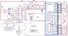
도 2는 본 발명에서의 배터리의 충, 방전 및 재생장치의 블록도.
도 3은 본 발명에서 스위치부를 도시한 개략도.1 is a block diagram illustrating a battery regeneration process according to the present invention;
2 is a block diagram of a charging, discharging and regenerating apparatus for a battery in the present invention.
3 is a schematic view showing a switch unit according to the present invention.
이하, 첨부된 도면을 이용하여 본 발명에 대해 보다 구체적으로 살펴보도록 한다.Hereinafter, the present invention will be described in more detail with reference to the accompanying drawings.
우선, 본 발명에서의 배터리의 충, 방전 및 재생장치의 구성에 대해 살펴보도록 한다.First, the configuration of a battery charging / discharging and reproducing apparatus in the present invention will be described.
본 발명에서의 배터리의 충, 방전 및 재생장치(100)는 도 1에서 도시된 바와 같이 다수의 배터리 셀(1)을 재생하기 위한 것이다.The battery charging, discharging and regenerating
이를 위해 본 발명은 다수의 배터리 셀(1)의 충전, 방전, 재생 작업을 실시할 수 있도록 구성된다.To this end, the present invention is configured to be capable of charging, discharging, and regenerating a plurality of
우선, 전원 공급부(10)는 도 2에서와 같이 통상의 전원을 공급하기 위한 구성으로서 상세한 설명은 생략하도록 한다.First, the
다음으로, 충전부(20)는 다수의 배터리 셀(1)을 충전할 수 있는 전류 및 전압을 변환하는 구성이다.Next, the
다음으로, 방전부(30)는 다수의 배터리 셀(1)을 완전히 방전시키기 위한 구성이다.Next, the
여기서, 다수의 배터리 셀(1)의 방전은 정해진 시간 내에 고전류를 이용해 실시하여야 하는 만큼 고전류를 생성할 수 있는 수단이 포함되어야만 한다.Here, the discharge of the plurality of
다음으로, 재생부(40)는 다수의 배터리 셀(1)을 재생하기 위한 구성이다.Next, the reproducing
더욱 구체적으로는, 상기 재생부(40)는 고전압을 인가하여 도면에는 도시하지 않았지만 배터리를 구성하는 전극에 부착된 황산을 탈락시켜 다수의 배터리 셀(1)을 재생시키는 구성이기 때문에 고압을 발생할 수 있는 수단(도면에 미도시)이 포함되어야만 한다.More specifically, the
다음으로, 스위치부(50)는 충, 방전부(20, 30)와 다수의 배터리 셀(1) 사이에 다수의 제1, 2 단자(51, 52)가 엑추에이터(53)에 의해 구동하도록 작동한다.Next, the
즉, 상기 스위치부(50)의 다수의 제1, 2 단자(51, 52)는 평상시 및 재생부(40)를 통한 다수의 배터리 셀(1)의 재생시에는 떨어져 있어 전기적으로 연결되지 않은 상태가 된다.That is, the first and
그러다가 사용자가 충전부(20) 및 방전부(30)를 통해 다수의 배터리 셀(1)을 충, 방전할 때에는 제어부(60)에서 다수의 제1, 2 단자(51, 52) 중 어느 하나의 단자를 구동하도록 구성된 엑추에이터(53)를 구동시켜 다수의 제1, 2 단자(51, 52)가 접촉하도록 작동한다.When the user charges and discharges a plurality of
여기서, 다수의 배터리 셀(1)의 방전시에는 고전류를 이용하여 방전을 실시하게 되는 만큼 도 3에서와 같이 상기 엑추에이터(53)를 통한 다수의 제1, 2 단자(51, 52)의 가압은 매우 강한 힘으로 다수의 제1, 2 단자(51, 52)가 맞닿아 있을 수 있도록 구성하여야만 한다.As shown in FIG. 3, since the first and
만약, 가압력이 약해지게 되어 접촉면 일부가 떨어지게 되면 다수의 제1, 2 단자(51, 52)가 고전류에 의해 아크 방전이 발생할 수 있기 때문이다.If the pressing force is weakened and a part of the contact surface is dropped, arc discharge may occur due to high currents in the first and
따라서, 상술한 엑추에이터(53)는 특별히 한정 짓는 것은 아니지만 대략 100kg 정도의 힘을 발생할 수 있는 실린더 또는 모터를 이용하는 것이 좋다.Therefore, although the
특히, 상술한 다수의 제1, 2 단자(51, 52)는 외부에 노출되어 있어 다수의 제1, 2 단자(51, 52)가 먼지 등의 이물질이 쌓일 수 있게 되며 이럴 경우 스파크가 발생할 수도 있다.Particularly, since the first and
이에 본 발명에서는 상기 다수의 제1, 2 단자(51, 52)의 형성시 경사각을 준 상태로 제작하여 다수의 제1, 2 단자(51, 52)가 접촉하는 면에 이물질 등이 묻어있지 않도록 할 수도 있다.Accordingly, in the present invention, when the first and
다음으로, 제어부(60)는 상술한 전원 공급부(10)를 통해 전원을 인가받으며, 충, 방전부(20, 30) 및 재생부(40)와 연동하여 작동할 수 있도록 구성된다.The
즉, 상기 제어부(60)는 평상시 및 고압을 발생하는 재생부(40)의 작동시에는 스위치부(50)의 다수의 제1, 2 단자(51, 52)가 연결되지 않도록 하여 충, 방전부(20, 30)와 재생부(40)가 전기적으로 연결되지 않도록 제어하고, 재생부(40)가 작동하지 않는 상태에서 충, 방전부(20, 30)가 작동하면 제어부(60)가 엑추에이터(53)를 구동시켜 다수의 제1, 2 단자(51, 52)가 맞닿도록 하여 전기적으로 연결될 수 있도록 작동한다.That is, the
특히, 상술한 제어부(60)는 스위치부(50)의 엑추에이터(53)를 구동하기 위한 전원을 검출하여 엑추에이터(53)가 작동하였을 때에만 충, 방전부(20, 30)로 전원을 인가하도록 제어도 하게 된다.Particularly, the
한편, 본 발명에서는 상기 충, 방전부(20, 30)와 스위치부(50) 사이에 바이패스부(70)를 더 포함하여 구성할 수 있다.Meanwhile, in the present invention, a
상기 바이패스부(70)는 상술한 충전부(20) 및 방전부(30)와 다수의 배터리 셀(1)을 연결하는 연결라인 상에서 어느 하나의 배터리 셀(1)과 이웃하는 배터리 셀(1) 사이에 배치되는 바이패스 유닛(71)이 배터리 셀(1)의 개수만큼 형성되어 있다.The
이러한, 바이패스부(70)는 바이패스 유닛(71)에서 해당 배터리 셀(1)의 전압 및 전류를 측정할 수 있음은 물론, 어느 하나의 배터리 셀(1)에서 측정된 전압 및 전류가 기준치를 벗어날 경우에는 해당 배터리 셀(1)로 유입되는 전원을 차단할 수 있도록 바이 패스시켜 이웃하는 배터리 셀(1)로 전원이 인가되도록 작동하게 되며, 이는, 충전부(20)를 통한 충전 및 방전부(40)를 통한 방전시에 구동이 이루어지게 된다.The
특히, 제어부(60)는 상술한 전원 공급부(10)에서 전원을 인가받아 충전부(20), 방전부(30), 재생부(40)에 전원을 인가하는 한편 위의 구성들과 연동하여 각 구성요소들을 제어할 수 있도록 이루어져 있다.Particularly, the
즉, 제어부(60)는 다수의 배터리 셀(1)의 충, 방전시 바이패스부(70)를 통해 해당 배터리 셀(1)로 유입되는 전류 및 전압이 기준치를 벗어남을 인지할 경우 바이스패스부(70)에 신호를 송신해 전원이 바이패스 되도록 할 수 있는 것이다.That is, when the
상기와 같은 구성으로 이루어진 상기와 같은 구성으로 이루어진 본 발명에 따른 배터리의 충, 방전 및 재생장치의 작용효과에 대해 살펴보면 다음과 같다.The operation and effect of the charging, discharging and regenerating apparatus of the present invention having the above-described constitution will be described below.
우선, 본 발명에서의 배터리의 충, 방전 및 재생장치(100)는 충, 방전부(20, 30)와 재생부(40)가 제어부(60)를 통해 전기적으로 연결된 상태를 유지하여 재생하고자 하는 다수의 배터리 셀(1)을 본 발명을 통해 충전, 방전 및 재생을 한번에 실시함으로써 중량이 무거운 다수의 배터리 셀(1)을 이동시키지 않아도 되어 작업성 및 편의성을 향상시킬 수 있는 효과를 얻을 수 있다.First, the charging, discharging and reproducing
즉, 통상의 충, 방전부(20, 30)는 배터리 셀(1)의 전체 전압, 예컨대, 2V의 배터리 셀(1)이 24개수 일 경우 약 48 ∼ 54V의 비교적 낮은 저전압에서 구동될 수 있도록 구성된다.That is, the normal charging and
하지만, 재생부(40)는 다수의 배터리 셀(1)의 전극에 붙은 황산을 떼어내기 위해 대략 1,000V 이상의 고압을 인가하여야만 한다.However, the
만약, 재생부(40)를 구동시킨 상태에서 충, 방전부(20, 30)가 재생부(40)와 전기적으로 연결된 상태이게 되면 재생부(40)의 전압에 의해 충, 방전부(20, 30)가 견디지 못하고 파손되는 문제가 발생하게 된다.If the charging and discharging
이에 본 발명에서는 충, 방전부(20, 30)와 다수의 배터리 셀(1) 사이에 스위치부(50)를 형성하여 평상시 및 재생부(40)가 작동할 때에는 스위치부(50)의 다수의 제1, 2 단자(51, 52)가 떨어져 있어 전기적으로 연결되지 않도록 함으로써 재생부(40)가 구동하더라도 충, 방전부(20, 30)에 영향을 미치지 않도록 함으로써 충, 방전부(20, 30)와 재생부(40)를 선택적으로 사용할 수 있도록 구성하여 작업성 및 편의성을 향상시킬 수 있게 되는 것이다.In the present invention, when the
또한, 충, 방전부(20, 30)의 구동시에는 엑추에이터(53)에 의해 다수의 제1, 2 단자(51, 52)가 접촉하여 전기적으로 연결되어 배터리 셀(1)의 충전 및 방전을 실시할 수 있게 된다.When the charging and discharging
한편, 상술한 방전부(30)를 통한 배터리 셀(1)의 방전은 정해진 시간 내에 배터리 셀(1) 내의 에너지를 모두 소진시켜야만 한다.On the other hand, the discharge of the
따라서, 방전시에는 고전류가 발생하게 되는데, 상술한 다수의 제1, 2 단자(51, 52)의 접촉면이 완전히 밀착되지 않은 상태일 경우 아크 방전이 발생하게 된다.Therefore, a high current is generated at the time of discharging. When the contact surfaces of the first and
이에 본 발명에서는 높은 가압력을 형성할 수 있는 실린더 또는 모터 중 어느 하나의 수단을 이용하여 가압함으로써 다수의 제1, 2 단자(51, 52)의 접촉면이 완전히 밀착될 수 있도록 하여 아크 방전이 발생하지 않도록 작용하게 된다.Accordingly, in the present invention, the contact surfaces of the first and
더욱이, 상술한 스위치부(50)의 다수의 제1, 2 단자(51, 52)는 경사각을 형성한 형태로 구성되어 먼지 등으로 인한 스파크의 발생도 막을 수 있는 효과를 얻을 수 있다.Moreover, the first and
또한, 본 발명에서는 스위치부(50)의 엑추에이터(53)를 작동시키는 전원이 인가되었는지 여부를 검출하여 엑추에이터(53)의 작동이 이루어진 것으로 판별될 때에만 제어부(60)에서 충, 방전부(20, 30)를 구동하기 위한 전원을 공급하도록 작동하여 안전사고를 방지할 수 있는 효과도 얻을 수 있게 된다.In the present invention, only when it is determined that the power source for operating the
한편, 본 발명에서는 바이패스부(70)를 통해 다수의 배터리 셀(1)의 충, 방전 및 재생 작업이 끊김 없이 연속적으로 이루어질 수 있어 작업시간을 대폭 단축할 수 있는 효과를 얻을 수 있다.Meanwhile, in the present invention, charging, discharging and regenerating operations of a plurality of
즉, 본 발명에서 바이패스부(70)는 어느 하나의 배터리 셀(1)과 이웃하는 배터리 셀(1) 사이에 배치되어 어느 하나의 배터리 셀(1)의 전류, 전압을 검출할 수 있음은 물론, 해당 배터리 셀(1)로 유입되는 전원을 차단하여 다른 이웃하는 배터리 셀(1)로 바이패스 시킬 수 있는 다수의 바이패스 유닛(71)이 구성되어 있다.That is, in the present invention, the
이러한, 바이패스부(70)는 다수의 배터리 셀(1)의 충전시 어느 하나의 배터리 셀(1)에 과전압 또는 일부 고장으로 인한 쇼트가 나거나 과전류가 흐르게 되면 바이패스 유닛(71)이 이웃하는 배터리 셀(1)로 전원을 바이패스 시켜 해당 배터리 셀(1)의 파손을 방지할 수 있게 된다.When the
또한, 배터리 셀(1)의 방전시 다수의 배터리 셀(1)은 순차적으로 방전이 이루어지게 되는데, 이때에, 이미 방전이 완료된 배터리 셀(1)이 발생할 경우 이를 인지하여 바이패스 시킴으로써 방전의 효율성을 높일 수 있게 된다.In addition, when a
더욱이 본 발명은 각각의 배터리 셀(1) 상태를 다수의 바이패스 유닛(71)이 모니터링 하기 때문에 충전량이 충분치 않은 배터리 셀(1)을 손쉽게 선별할 수 있다.Furthermore, since the plurality of
따라서, 각각의 배터리 셀(1)을 검사하지 않더라도 개별적인 검사가 이루어질 수 있어 작업성을 향상시킬 수 있는 효과를 얻을 수 있게 되는 것이다.Therefore, even if each
한편, 상기와 같은 구성 및 작용효과가 있는 배터리의 충, 방전 및 재생장치를 이용하여 배터리 셀을 재생하는 과정에 대해 살펴보면 다음과 같다.The process of regenerating the battery cell using the charging, discharging and regenerating apparatus of the battery having the above-described configuration and operation effects will be described.
1. 1차 충전단계1. Primary charge stage
본 단계는 재생하고자 하는 다수의 배터리 셀(1)을 재생하기 전에 각각의 배터리 셀(1)을 확인하기 위해 각각의 배터리 셀(1)을 완전히 충전하기 위한 단계이다.This step is a step for fully charging each
이를 위해, 본 발명에서는 배터리의 충, 방전 및 재생장치(100)를 이용하여 다수의 배터리 셀(1)을 충전한다.To this end, in the present invention, a plurality of
여기서, 본 발명에서의 배터리의 충, 방전 및 재생장치(100)는 비교적 저전압으로 구동하는 충, 방전부(20, 30)와 고전압으로 구동하는 재생부(40)가 같이 형성되어 있기 때문에, 평상시에는 충, 방전부(20, 30)와 다수의 배터리 셀(1)이 전기적으로 연결되어 있지 않다.Here, in the battery charging / discharging / regenerating
따라서, 위와 같이 다수의 배터리 셀(1)의 충전을 위해서는 스위치부(50)의 다수의 제1, 2 단자(51, 52)를 접촉시켜 충, 방전부(20, 30)와 재생부(40) 및 충, 방전부(20, 30)와 다수의 배터리 셀(1)이 전기적으로 연결된 상태에서 충전부(20)를 구동하여 다수의 배터리 셀(1)의 충전을 실시하면 된다.Therefore, in order to charge the plurality of
여기서, 본 발명의 배터리의 충, 방전 및 재생장치(100)에는 어느 하나의 배터리 셀(1)과 이웃하는 배터리 셀(1)과 전기적으로 연결되되, 배터리 셀(1)와 동일한 개수로 이루어진 바이패스 유닛(71)으로 이루어진 바이패스부(70)가 더 구성되어 있다.The battery charging and discharging
상기 바이패스부(70)의 바이패스 유닛(71)은 앞서 설명한 것과 같이 해당 배터리 셀(1)의 전류, 전압을 검출할 수 있음은 물론, 전압, 전류 및 기타 배터리 셀(1)의 이상이 있을 경우 전원을 바이패스시킬 수 있도록 작동하게 됨은 물론, 정상적으로 충전 및 방전이 완료되면 전원을 바이스패스 시켜 그 다음 배터리 셀(1)로 전원이 인가되도록 작동한다.The
따라서, 본 단계에서 과전류, 과전압 및 배터리 셀(1)의 이상으로 인한 이상징후 및 배터리 셀(1)이 정상적으로 충전이 이루어진 후에는 그 다음의 배터리 셀(1)로 전원이 바이패스되도록 작동하게 됨은 당연한 것이다.Therefore, in this step, the overcurrent, the overvoltage, and the abnormality indication due to the abnormality of the
이러한, 바이패스부(70)를 통해 어느 하나의 배터리 셀(1)의 이상으로 인한 작업이 중단되는 현상을 방지할 수 있음은 물론, 특정 배터리 셀(1)의 파손을 방지하면서 허전압 발생에 따른 작업자의 작업량을 과중시키는 현상을 방지할 수 있게 된다.The
특히, 상기 바이패스 유닛(71)은 각각의 배터리 셀(1)과 1 : 1 대응하도록 구성되어 각각의 배터리 셀(1)을 개별 모니터링할 수 있는 효과도 얻을 수 있다.Particularly, the
2. 1차 방전단계2. Primary Discharge Phase
본 단계는 상술한 1차 충전단계에서 완전히 충전된 다수의 배터리 셀(1)을 방전시켜 다수의 배터리 셀(1)의 상태를 확인하기 위한 단계이다.This step is for confirming the state of a plurality of
즉, 상술한 다수의 배터리 셀(1)은 최소 5년 동안 사용 또는 방치해 놓은 배터리 셀(1)로서 시간이 지남에 따라 다수의 배터리 셀(1)의 전극에 황산이 부착되어 에너지를 충전하기 위한 공간이 줄어든 상태의 것들이다.That is, in the above-described
이러한, 다수의 배터리 셀(1)은 각각 충전되는 양이 다르기 때문에 상기 1차 충전단계를 통해 다수의 배터리 셀(1)을 완전히 충전한 후 본 단계를 실시하게 되면 충전량이 각각 다르기 때문에 방전도 각각 다른 시간이 이루어지게 된다.Since the plurality of
따라서, 본 발명은 이러한 데이터를 통해 각각의 배터리 셀(1)의 상태를 파악할 수 있게 된다.Therefore, the present invention can grasp the state of each
여기서, 상기 다수의 배터리 셀(1)의 방전은 배터리의 충, 방전 및 재생장치(100)의 방전부(30)를 통해 실시할 수 있다.Here, the discharge of the plurality of
특히, 본 단계는 저전압, 고전류를 이용하여 이루어지게 된다.Particularly, this step is performed by using low voltage and high current.
따라서, 스위치부(50)의 다수의 제1, 2 단자(51, 52)의 접촉면이 강한 힘으로 밀착되지 않게 될 경우 아크 방전이 발생하게 되어 화재가 발생할 수 있다.Therefore, when the contact surfaces of the first and
이에 본 발명의 배터리의 충, 방전 및 재생장치(100)의 스위치부(50)에는 모터 또는 실린더 등으로 이루어진 엑추에이터(53)가 다수의 제1, 2 단자(51, 52) 중 어느 하나를 강한 힘으로 구동시킬 수 있도록 구성되어 위와 같이 아크 방전에 따른 화재를 예방할 수 있게 된다.Therefore, in the
본 단계도 앞선 1차 충전단계에서와 마찬가지로 어느 하나의 배터리 셀(1)의 방전이 완료되거나 배터리 셀(1)의 이상이 감지되면 전원이 바이패스부(70)에 의해 바이패스되어 그 다음의 배터리 셀(1)의 방전을 실시할 수 있도록 작동하게 된다.The power is bypassed by the
3. 재생단계3. Playback phase
본 단계는 재생하고자 하는 다수의 배터리 셀(1)의 전극에 들러붙은 황산을 떨어뜨려 다수의 배터리 셀(1)의 충전량을 향상시키기 위한 단계이다.In this step, sulfuric acid adhered to the electrodes of the plurality of
본 단계를 위해서는 배터리의 충, 방전 및 재생장치(100)의 재생부(40)를 이용하여 재생작업을 실시하여야 한다.For this step, a regeneration operation must be performed using the
여기서, 다수의 배터리 셀(1)의 전극에 붙어있는 황산을 떨어뜨리기 위해서는 앞서 설명한 바와 같이 대략 1,000V 이상의 전압을 이용하여야만 하는데, 배터리의 충, 방전 및 재생장치(100)의 충, 방전부(20, 30)는 낮은 전압(48 ∼ 50V)에서 구동할 수 있도록 구성되어 있어, 위와 같이 재생부(40)의 구동시 파손이 발생하게 된다.Here, in order to drop sulfuric acid attached to the electrodes of the
이에 본 발명에서는 배터리의 충, 방전 및 재생장치(100)의 스위치부(50)의 다수의 제1, 2 단자(51, 52)를 떨어뜨려 충, 방전부(20, 30)와 재생부(40) 및 충, 방전부(20, 30)와 배터리 셀(1)이 전기적으로 연결되지 않은 상태로 만든 후 재생부(40)를 통해 배터리 셀(1)의 재생작업을 실시하게 된다.Accordingly, in the present invention, a plurality of first and
따라서, 본 발명은 고전압으로 작동하는 재생부(40)와 저전압으로 작동하는 충, 방전기(20, 30)를 모두 배터리의 충, 방전 및 재생장치(100)에 형성한 한 후 다수의 배터리 셀(1)의 이동없이 충, 방전 및 재생작업을 한번에 실시할 수 있어 작업성 향상, 편의성 향상과 더불어 작업시간을 단축할 수 있게 된다.Accordingly, the present invention is characterized in that the
4. 2차 충전 단계4. Secondary charging stage
본 단계는 상술한 재생단계를 통해 재생이 완료된 다수의 배터리 셀(1)을 충전시키기 위한 단계이다.This step is for charging the plurality of
이를 위해 앞선 재생단계에서 떨어뜨린 스위치부(50)의 제1, 2 단자(51, 52)를 엑추에이터(53)를 통해 밀착시켜 충전부(20)와 다수의 배터리 셀(1)이 전기적으로 연결될 수 있도록 구동시킨 후 충전을 실시하게 된다.To this end, the first and
본 단계에서도 앞선 1차 충전단계에서와 마찬가지로 바이패스부(70)에 의해 과전류, 과전압 및 배터리 셀(1)의 이상이 발생할 경우 전원을 바이패스시켜 연속적으로 작업이 이루어져 작업자의 편의성 및 작업시간을 단축시킴은 물론, 배터리 셀(1)을 각각 모니터링하여 작업자의 편의성을 향상시킬 수 있게 된다.In this step, as in the case of the first primary charging step, when the overcurrent, overvoltage, and an abnormality of the
특히, 상기 바이패스 유닛(71)은 각각의 배터리 셀(1)과 1 : 1 대응하도록 구성되어 각각의 배터리 셀(1)을 개별 모니터링할 수 있는 효과도 얻을 수 있다.Particularly, the
5. 2차 방전단계5. Secondary discharge step
본 단계는 상술한 2차 충전 단계를 통해 충전한 재생이 완료된 다수의 배터리 셀(1)을 방전시키기 위한 단계이다.This step is a step for discharging the plurality of regenerated
특히, 본 단계는 재생이 완료된 후에 충전 및 방전시켜 다수의 배터리 셀(1)의 재생이 어느 정도 이루어졌는지를 확인하기 위한 단계이다.In particular, this step is a step for confirming to what extent the reproduction of a plurality of
즉, 다수의 배터리 셀(1)을 충전하게 되면 에너지가 축적되며, 이를 동일 조건으로 방전시키게 되면 각각의 배터리 셀(1)에 충전된 양을 검출할 수 있게 된다.That is, energy is accumulated when a plurality of
6. 선별단계6. Selection step
본 단계는 상기 2차 방전단계에서 각각의 배터리 셀(1)을 방전시킨 후 사용자가 원하는 정도로 충전이 이루어진 양질의 배터리 셀(1)과 재생이 제대로 이루어지지 않았거나 또는 망실된 배터리 셀(1)을 선별하여 요구에 충족되는 배터리 셀(1)을 선별하기 위한 단계이다.In this step, after discharging each
이러한, 다수의 배터리 셀(1)의 충전량에 따른 데이터는 각각의 배터리 셀(1)과 연결되어 있는 바이패스부(70)의 바이패스 유닛(71)을 통해 데이터를 확보할 수 있다.The data according to the charged amount of the plurality of
7. 3차 충전단계7. Third charge stage
본 단계는 상기 선별단계에서 충전량을 충족한 재생된 다수의 배터리 셀(1)을 충전하기 위한 단계로서 본 단계를 통해 다수의 배터리 셀(1)의 재생작업이 완료된다.This step is a step for charging a plurality of regenerated
상술한 실시 예는 본 발명의 가장 바람직한 예에 대하여 설명한 것이지만, 상기 실시 예에만 한정되는 것은 아니며, 본 발명의 기술적 사상을 벗어나지 않는 범위내에서 다양한 변형이 가능하다는 것은 본 발명이 속하는 기술분야에서 통상의 기술자들에게 있어 명백한 것이다.Although the present invention has been described in connection with what is presently considered to be the most practical and preferred embodiment, it is to be understood that the invention is not limited to the disclosed embodiments, but, on the contrary, It is obvious to the technicians of.
1 : 배터리 셀
10 : 전원 공급부
20 : 충전부
30 : 방전부
40 : 재생부
50 : 스위치부
51 : 제1 단자 52 : 제2 단자 53 : 엑추에이터
60 : 제어부
70 : 바이패스부
71 : 바이패스 유닛
100 : 배터리의 충, 방전 및 재생장치1: Battery cell
10: Power supply
20:
30: discharge unit
40:
50:
51: first terminal 52: second terminal 53: actuator
60:
70: Bypass section
71: Bypass unit
100: Battery charging, discharging and regenerating device
Claims (3)
Translated fromKorean배터리의 충, 방전 및 재생장치의 스위치부에 형성된 다수의 제1, 2 단자를 접촉시킨 후 충전하고자 하는 다수의 배터리 셀에 배터리의 충, 방전 및 재생장치의 충전부를 이용하여 충전하는 1차 충전단계;
상기 1차 충전 이후 배터리의 충, 방전 및 재생장치의 방전부를 이용하여 다수의 배터리 셀에 충전된 에너지를 방전시키기 위한 1차 방전단계;
상기 배터리의 충, 방전 및 재생장치의 스위치부에 형성된 다수의 제1, 2 단자를 떨어뜨려 충, 방전부와 재생부가 전기적으로 연결되지 않도록 한후, 상기 1차 방전된 다수의 배터리 셀을 배터리의 충, 방전 및 재생장치의 재생장치를 이용하여 배터리 셀의 전극에 붙은 황산을 떨어뜨려 다수의 배터리 셀을 재생하는 재생단계;
상기 재생단계를 통해 재생된 다수의 배터리 셀의 재생율을 확인하기 위해 배터리의 충, 방전 및 재생장치의 스위치부의 다수의 제1, 2 단자를 접촉시켜 충전부와 배터리 셀이 전기적으로 연결되도록 한 후 배터리의 충, 방전 및 재생장치의 충전부를 이용해 다수의 배터리 셀을 충전하는 2차 충전단계;
상기 2차 충전된 다수의 배터리 셀을 배터리의 충, 방전 및 재생장치의 방전부를 이용하여 완전히 방전시키는 2차 방전단계;
상기 방전단계 이후 각각의 배터리 셀의 전류량을 검출하여 허용기준을 충족하는 배터리 셀을 골라내는 선별단계;
상기 선별단계에서 선별된 다수의 배터리 셀을 배터리의 충, 방전 및 재생장치의 충전부를 이용하여 최종 충전하는 3차 충전단계;로 이루어져 있어,
다수의 배터리 셀의 재생작업시 배터리의 충, 방전 및 재생장치로 다수의 배터리 셀의 충, 방전 및 재생작업을 한번에 실시하는 것에 특징이 있는 배터리의 충, 방전 및 재생장치를 이용한 배터리 재생방법.A power supply unit for supplying power to a plurality of battery cells, a charging unit charging the plurality of battery cells, a discharger for discharging the plurality of battery cells, a regenerating unit for regenerating the battery cells, A plurality of first and second battery cells which are formed between the charge and discharge units and the battery cells and operate so that the charge and discharge units and the regeneration unit are not electrically connected at the time of normal operation and the operation of the regeneration unit, The first and second terminals being connected to the first and second terminals, respectively, the first and second terminals being connected to each other, A switch unit which presses the two terminals with a strong force to move the current so as to prevent arc discharge from occurring; A plurality of first and second terminals of the switch unit are interlocked with the switch unit at the time of normal operation or at the time of operation of the regeneration unit and a control unit operable to abut the first and second terminals of the switch unit at the time of charge / And a switching unit that is disposed between the discharging unit and the switch unit to bypass the power supplied to the battery cell when the current and the voltage in the battery cell are out of the reference value, And a bypass unit including a plurality of bypass units for supplying power to the battery cells. The battery cells are connected to the adjacent battery cells when a short circuit occurs due to the overcharging, the overcurrent and the failure of the battery cells during the first and second charging steps and the first and second discharging steps. It is possible to monitor the state of each battery cell by sequentially charging, discharging and regenerating a plurality of battery cells at a time A battery recycling method using a charge, discharge, and regenerator,
A plurality of battery cells to which a plurality of first and second terminals formed in a switch unit of a charging, discharging and regenerating apparatus of a battery are brought into contact and then charged are charged using a charging unit of the battery and a charging unit of the battery, step;
A primary discharging step of discharging the energy charged in the plurality of battery cells by using the discharging part of the charging, discharging and regenerating device of the battery after the primary charging;
A plurality of first and second terminals formed on a switch unit of the charging, discharging and regenerating unit of the battery are dropped so that the charging and discharging unit and the regenerating unit are not electrically connected to each other, A regeneration step of regenerating a plurality of battery cells by dropping sulfuric acid attached to an electrode of the battery cell using a regeneration device of the charge, discharge and regeneration device;
A plurality of first and second terminals of the switch unit of the battery charging / discharging and regenerating apparatus are contacted to check the refresh rate of the plurality of battery cells reproduced through the regeneration step so that the charging unit and the battery cell are electrically connected to each other, A secondary charging step of charging the plurality of battery cells using the charging unit of the charging, discharging and regenerating apparatus of the charging and discharging unit;
A secondary discharging step of discharging a plurality of the secondary charged battery cells by using the discharging unit of the charging, discharging and regenerating apparatus of the battery;
Detecting a current amount of each battery cell after the discharging step and selecting a battery cell that meets a tolerance criterion;
And a third charging step of final charging the plurality of battery cells selected in the selecting step using the charging unit of the battery and the charging unit of the reproducing apparatus,
Discharging and regenerating operations of a plurality of battery cells are carried out at one time by charging, discharging and regenerating the batteries during the regeneration work of a plurality of battery cells.
Priority Applications (1)
| Application Number | Priority Date | Filing Date | Title |
|---|---|---|---|
| KR1020170138323AKR101859176B1 (en) | 2017-10-24 | 2017-10-24 | Method of battry recycling by using charging, over-discharging, recycling apparatus for battery |
Applications Claiming Priority (1)
| Application Number | Priority Date | Filing Date | Title |
|---|---|---|---|
| KR1020170138323AKR101859176B1 (en) | 2017-10-24 | 2017-10-24 | Method of battry recycling by using charging, over-discharging, recycling apparatus for battery |
Publications (1)
| Publication Number | Publication Date |
|---|---|
| KR101859176B1true KR101859176B1 (en) | 2018-06-28 |
Family
ID=62780114
Family Applications (1)
| Application Number | Title | Priority Date | Filing Date |
|---|---|---|---|
| KR1020170138323AActiveKR101859176B1 (en) | 2017-10-24 | 2017-10-24 | Method of battry recycling by using charging, over-discharging, recycling apparatus for battery |
Country Status (1)
| Country | Link |
|---|---|
| KR (1) | KR101859176B1 (en) |
Cited By (1)
| Publication number | Priority date | Publication date | Assignee | Title |
|---|---|---|---|---|
| KR102412867B1 (en)* | 2021-11-16 | 2022-06-24 | 이진수 | Testing device for charging and discharging of secondary battery |
Citations (4)
| Publication number | Priority date | Publication date | Assignee | Title |
|---|---|---|---|---|
| KR20110033757A (en)* | 2009-09-25 | 2011-03-31 | 임만식 | Battery Recharge / Charge Device |
| KR20120010805A (en)* | 2010-07-27 | 2012-02-06 | 경 영 이 | How to play and charge the battery |
| KR20120046628A (en)* | 2010-11-02 | 2012-05-10 | (주)세성유니버스 | Recycling device for rechargeable battery |
| KR20130001239A (en)* | 2010-02-08 | 2013-01-03 | 포투 인텔렉츄얼 프로퍼티 아게 | High-current battery system and method for controlling a high-current battery system |
- 2017
- 2017-10-24KRKR1020170138323Apatent/KR101859176B1/enactiveActive
Patent Citations (4)
| Publication number | Priority date | Publication date | Assignee | Title |
|---|---|---|---|---|
| KR20110033757A (en)* | 2009-09-25 | 2011-03-31 | 임만식 | Battery Recharge / Charge Device |
| KR20130001239A (en)* | 2010-02-08 | 2013-01-03 | 포투 인텔렉츄얼 프로퍼티 아게 | High-current battery system and method for controlling a high-current battery system |
| KR20120010805A (en)* | 2010-07-27 | 2012-02-06 | 경 영 이 | How to play and charge the battery |
| KR20120046628A (en)* | 2010-11-02 | 2012-05-10 | (주)세성유니버스 | Recycling device for rechargeable battery |
Cited By (1)
| Publication number | Priority date | Publication date | Assignee | Title |
|---|---|---|---|---|
| KR102412867B1 (en)* | 2021-11-16 | 2022-06-24 | 이진수 | Testing device for charging and discharging of secondary battery |
Similar Documents
| Publication | Publication Date | Title |
|---|---|---|
| US4616170A (en) | Arrangement and method for operating an electrochemical storage device | |
| EP2879268B1 (en) | Charging/discharging device | |
| CN102742066B (en) | Heavy current battery system and the method being used for controlling heavy current battery system | |
| CN101667737B (en) | Power supply system and battery charging/discharging control method | |
| JP6733783B2 (en) | Power supply device and diagnostic method for diagnosing abnormality of power supply device | |
| CN102386653A (en) | Discharger and discharger control method | |
| KR101859336B1 (en) | A charging, over-discharging, recycling apparatus for battery | |
| CN107219467B (en) | Transformer substation storage battery nuclear capacity device with sulfur removal and repair functions and method | |
| CN103066671A (en) | Uniform charging method and uniform charging device for lithium battery packs | |
| CN102938477A (en) | Charging method and apparatus for storage battery | |
| CN113924708B (en) | Method for operating an electrical energy store, electrical energy store and device | |
| JP2011200023A (en) | Uninterruptible power supply device | |
| JP5361594B2 (en) | Lithium ion secondary battery system and power supply method to management device | |
| JP4015126B2 (en) | DC power supply system | |
| JP2018161000A (en) | Battery pack charge control device and charge control method | |
| KR20180050156A (en) | Apparatus for managing energy storage system and method for operating the same | |
| KR101859176B1 (en) | Method of battry recycling by using charging, over-discharging, recycling apparatus for battery | |
| JP4485489B2 (en) | DC power supply system and test method thereof, and program for executing DC power supply system test method | |
| KR20120039423A (en) | Apparatus and method for recycling and charging simultaneously a battery | |
| KR101004762B1 (en) | Battery Restoration Device and Method | |
| JP2012125122A (en) | Power system | |
| JP5541682B2 (en) | Lithium-ion battery charging system and charging method | |
| KR101425394B1 (en) | Power Converting System with Diagnostic or Regeneration Function for Battery | |
| JPWO2004034074A1 (en) | Battery management method and apparatus | |
| JP2018011447A (en) | Large-capacity storage battery system |
Legal Events
| Date | Code | Title | Description |
|---|---|---|---|
| PA0109 | Patent application | Patent event code:PA01091R01D Comment text:Patent Application Patent event date:20171024 | |
| PA0201 | Request for examination | ||
| PA0302 | Request for accelerated examination | Patent event date:20171024 Patent event code:PA03022R01D Comment text:Request for Accelerated Examination | |
| PE0902 | Notice of grounds for rejection | Comment text:Notification of reason for refusal Patent event date:20171114 Patent event code:PE09021S01D | |
| PE0701 | Decision of registration | Patent event code:PE07011S01D Comment text:Decision to Grant Registration Patent event date:20180214 | |
| GRNT | Written decision to grant | ||
| PR0701 | Registration of establishment | Comment text:Registration of Establishment Patent event date:20180511 Patent event code:PR07011E01D | |
| PR1002 | Payment of registration fee | Payment date:20180511 End annual number:3 Start annual number:1 | |
| PG1601 | Publication of registration | ||
| PR1001 | Payment of annual fee | Payment date:20210322 Start annual number:4 End annual number:4 | |
| PR1001 | Payment of annual fee | Payment date:20220510 Start annual number:5 End annual number:5 | |
| PR1001 | Payment of annual fee | Payment date:20230510 Start annual number:6 End annual number:6 | |
| PR1001 | Payment of annual fee | Payment date:20240509 Start annual number:7 End annual number:7 |