KR101857945B1 - Biopsy device with motorized needle firing - Google Patents
Biopsy device with motorized needle firingDownload PDFInfo
- Publication number
- KR101857945B1 KR101857945B1KR1020137029812AKR20137029812AKR101857945B1KR 101857945 B1KR101857945 B1KR 101857945B1KR 1020137029812 AKR1020137029812 AKR 1020137029812AKR 20137029812 AKR20137029812 AKR 20137029812AKR 101857945 B1KR101857945 B1KR 101857945B1
- Authority
- KR
- South Korea
- Prior art keywords
- needle
- biopsy device
- launch
- coupling portion
- translatable
- Prior art date
- Legal status (The legal status is an assumption and is not a legal conclusion. Google has not performed a legal analysis and makes no representation as to the accuracy of the status listed.)
- Expired - Fee Related
Links
Images


Classifications
- A—HUMAN NECESSITIES
- A61—MEDICAL OR VETERINARY SCIENCE; HYGIENE
- A61B—DIAGNOSIS; SURGERY; IDENTIFICATION
- A61B10/00—Instruments for taking body samples for diagnostic purposes; Other methods or instruments for diagnosis, e.g. for vaccination diagnosis, sex determination or ovulation-period determination; Throat striking implements
- A61B10/02—Instruments for taking cell samples or for biopsy
- A61B10/0233—Pointed or sharp biopsy instruments
- A61B10/0266—Pointed or sharp biopsy instruments means for severing sample
- A61B10/0275—Pointed or sharp biopsy instruments means for severing sample with sample notch, e.g. on the side of inner stylet
- A—HUMAN NECESSITIES
- A61—MEDICAL OR VETERINARY SCIENCE; HYGIENE
- A61B—DIAGNOSIS; SURGERY; IDENTIFICATION
- A61B10/00—Instruments for taking body samples for diagnostic purposes; Other methods or instruments for diagnosis, e.g. for vaccination diagnosis, sex determination or ovulation-period determination; Throat striking implements
- A61B10/02—Instruments for taking cell samples or for biopsy
- A61B10/0233—Pointed or sharp biopsy instruments
- A61B10/0283—Pointed or sharp biopsy instruments with vacuum aspiration, e.g. caused by retractable plunger or by connected syringe
- A—HUMAN NECESSITIES
- A61—MEDICAL OR VETERINARY SCIENCE; HYGIENE
- A61B—DIAGNOSIS; SURGERY; IDENTIFICATION
- A61B10/00—Instruments for taking body samples for diagnostic purposes; Other methods or instruments for diagnosis, e.g. for vaccination diagnosis, sex determination or ovulation-period determination; Throat striking implements
- A61B10/02—Instruments for taking cell samples or for biopsy
- A61B2010/0208—Biopsy devices with actuators, e.g. with triggered spring mechanisms
- A—HUMAN NECESSITIES
- A61—MEDICAL OR VETERINARY SCIENCE; HYGIENE
- A61B—DIAGNOSIS; SURGERY; IDENTIFICATION
- A61B17/00—Surgical instruments, devices or methods
- A61B2017/0046—Surgical instruments, devices or methods with a releasable handle; with handle and operating part separable
- A—HUMAN NECESSITIES
- A61—MEDICAL OR VETERINARY SCIENCE; HYGIENE
- A61B—DIAGNOSIS; SURGERY; IDENTIFICATION
- A61B17/00—Surgical instruments, devices or methods
- A61B2017/00535—Surgical instruments, devices or methods pneumatically or hydraulically operated
- A61B2017/00561—Surgical instruments, devices or methods pneumatically or hydraulically operated creating a vacuum
- A—HUMAN NECESSITIES
- A61—MEDICAL OR VETERINARY SCIENCE; HYGIENE
- A61B—DIAGNOSIS; SURGERY; IDENTIFICATION
- A61B90/00—Instruments, implements or accessories specially adapted for surgery or diagnosis and not covered by any of the groups A61B1/00 - A61B50/00, e.g. for luxation treatment or for protecting wound edges
- A61B90/08—Accessories or related features not otherwise provided for
- A61B2090/0807—Indication means
- A61B2090/0808—Indication means for indicating correct assembly of components, e.g. of the surgical apparatus
Landscapes
- Health & Medical Sciences (AREA)
- Life Sciences & Earth Sciences (AREA)
- Medical Informatics (AREA)
- Engineering & Computer Science (AREA)
- Biomedical Technology (AREA)
- Heart & Thoracic Surgery (AREA)
- Pathology (AREA)
- Molecular Biology (AREA)
- Surgery (AREA)
- Animal Behavior & Ethology (AREA)
- General Health & Medical Sciences (AREA)
- Public Health (AREA)
- Veterinary Medicine (AREA)
- Surgical Instruments (AREA)
- Infusion, Injection, And Reservoir Apparatuses (AREA)
Abstract
Translated fromKoreanDescription
Translated fromKorean생검 샘플(biopsy sample)은 여러 디바이스를 사용하여 여러 의료 절차에서 여러 방식으로 획득되었다. 생검 디바이스(biopsy device)는 정위 가이드(stereotactic guidance), 초음파 가이드, MRI 가이드, PEM 가이드, BSGI 가이드 하에 사용되거나, 또는 다른 방식으로 사용될 수 있다. 예를 들어, 일부 생검 디바이스는 한 손으로 환자로부터 하나 이상의 생검 샘플을 캡처하기 위해 한 손을 사용하여 한번 삽입으로 사용자에 의하여 완전히 동작가능할 수 있다. 더욱이, 일부 생검 디바이스는 예를 들어 유체(예를 들어, 가압 공기, 염수(saline), 대기 공기, 진공 등)의 전달을 위해, 동력의 전달을 위해, 및/또는 명령 등의 전달을 위해 진공 모듈 및/또는 제어 모듈에 구속될 수 있다. 다른 생검 디바이스는 완전히 또는 적어도 부분적으로 다른 디바이스에 구속되거나 다른 방식으로 연결되지 않고 동작가능할 수 있다.Biopsy samples were obtained in different ways in different medical procedures using multiple devices. Biopsy devices can be used under stereotactic guidance, ultrasound guides, MRI guides, PEM guides, BSGI guides, or in other ways. For example, some biopsy devices may be fully operable by the user in one insertion with one hand to capture one or more biopsy samples from the patient with one hand. Moreover, some biopsy devices can be used for delivery of fluids (e.g., pressurized air, saline, atmospheric air, vacuum, etc.), for power delivery, and / Modules and / or control modules. Other biopsy devices may be fully or at least partially operable without being constrained or otherwise connected to another device.
단지 예시적인 생검 디바이스는 미국 특허 제5,526,822호(발명의 명칭: "Method and Apparatus for Automated Biopsy and Collection of Soft Tissue", 등록일: 1996년 6월 18일); 미국 특허 제6,086,544호(발명의 명칭: "Control Apparatus for an Automated Surgical Biopsy Device", 등록일: 2000년 7월 11일); 미국 공개 제2003/0109803호(발명의 명칭: "MRI Compatible Surgical Biopsy Device", 공개일: 2003년 6월 12일); 미국 공개 제2006/0074345호(발명의 명칭: "Biopsy Apparatus and Method", 공개일: 2006년 4월 6일); 미국 공개 제2007/0118048호(발명의 명칭: "Remote Thumbwheel for a Surgical Biopsy Device", 공개일: 2007년 5월 24일); 미국 공개 제2008/0214955호(발명의 명칭: "Presentation of Biopsy Sample by Biopsy Device", 공개일: 2008년 9월 4일); 미국 공개 제2009/0171242호(발명의 명칭: "Clutch and Valving System for Tetherless Biopsy Device", 공개일: 2009년 7월 2일); 미국 공개 제2010/0152610호(발명의 명칭: "Hand Actuated Tetherless Biopsy Device with Pistol Grip", 공개일: 2010년 6월 17일); 미국 공개 제2010/0160819호(발명의 명칭: "Biopsy Device with Central Thumbwheel", 공개일: 2010년 6월 24일); 미국 공개 제2010/0317997호(발명의 명칭: "Tetherless Biopsy Device with Reusable Portion", 공개일: 2010년 12월 16일); 및 미국 정식 특허 출원 제12/953,715호(발명의 명칭: "Handheld Biopsy Device with Needle Firing", 출원일: 2010년 11월 24일)에 개시되어 있다. 상기 언급된 미국 특허, 미국 특허 출원 공개 및 미국 정식 특허 출원 각각의 개시 내용은 본 명세서에 참조 문헌으로 병합된다.An exemplary biopsy device is disclosed in U.S. Patent No. 5,526,822 entitled " Method and Apparatus for Automated Biopsy and Collection of Soft Tissue ", issued June 18, 1996; U.S. Patent No. 6,086,544 entitled "Control Apparatus for an Automated Surgical Biopsy Device ", filed July 11, 2000); U.S. Publication No. 2003/0109803 (entitled "MRI Compatible Surgical Biopsy Device ", published on June 12, 2003); U.S. Publication No. 2006/0074345 entitled "Biopsy Apparatus and Method ", published on April 6, 2006); U.S. Publication No. 2007/0118048 (entitled " Remote Thumbwheel for a Surgical Biopsy Device ", published on May 24, 2007); U.S. Publication No. 2008/0214955 (entitled " Presentation of Biopsy Sample by Biopsy Device ", published on Sep. 4, 2008); US Patent Application Publication No. 2009/0171242 entitled " Clutch and Valving System for Tetherless Biopsy Device ", published on July 2, 2009); U.S. Publication No. 2010/0152610 (entitled " Hand Actuated Tetherless Biopsy Device with Pistol Grip ", published on June 17, 2010); U.S. Published Patent Application No. 2010/0160819 entitled "Biopsy Device with Central Thumbwheel ", published on June 24, 2010); &Quot; Tetherless Biopsy Device with Reusable Portion ", published on Dec. 16, 2010); And US Patent Application No. 12 / 953,715 entitled "Handheld Biopsy Device with Needle Firing" filed on November 24, 2010. The disclosures of each of the aforementioned US patents, U.S. patent application publications, and U.S. formal patent applications are incorporated herein by reference.
여러 시스템 및 방법이 생검 샘플을 획득하는데 만들어져 사용될 수 있으나, 본 발명자 전에는 그 누구도 첨부된 청구범위에 개시된 본 발명이 만들어지거나 사용된 적이 없는 것으로 믿어진다.Although several systems and methods can be made and used to obtain a biopsy sample, it is believed that none of the inventors have ever made or used the invention disclosed in the appended claims.
본 명세서는 본 발명을 구체적으로 적시하고 명확히 청구하는 청구범위로 종결되지만, 본 발명은 동일한 참조 부호가 동일한 요소를 나타내는 첨부 도면과 함께 특정 예의 이하 상세한 설명으로부터 더 잘 이해될 수 있는 것으로 생각된다. 도면에서 일부 구성부품(component) 또는 구성부품의 부분은 파선으로 도시되었다.
도 1은 예시적인 생검 디바이스의 여러 구성부품을 도시한 개략 블록도;
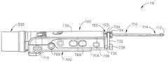
도 2는 서로 연결된 예시적인 생검 디바이스의 프로브(probe)와 홀스터(holster)의 사시도;
도 3은 프로브의 하부측과 홀스터의 상부측을 노출시키기 위하여 프로브를 홀스터로부터 분리시킨 도 2의 생검 디바이스의 사시도;
도 4a는 니들(needle)이 장전된 위치(armed position)에 있는 도 2의 생검 디바이스의 측면도;
도 4b는 니들이 발사 위치(fired position)에 있는 도 2의 생검 디바이스의 측면도;
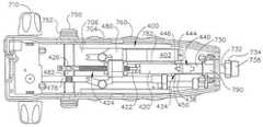
도 5는 상부 하우징 커버가 제거된 도 2의 생검 디바이스의 홀스터의 평면도;
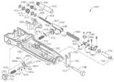
도 6은 도 5의 홀스터의 니들 발사 메커니즘(needle firing mechanism)의 분해 사시도;
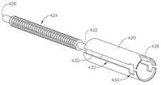
도 7은 도 6의 니들 발사 메커니즘의 리드 스크루(lead screw)와 발사 튜브(firing tube)의 측면도;
도 8은 도 7의 발사 튜브와 결합된(engaged) 도 5의 홀스터의 캠 레일(cam rail)의 횡단면 단부를 도시하는 도면;
도 9a는 니들 발사 메커니즘이 미리-장전된 배치(pre-armed configuration)에 있는 도 5의 홀스터의 평면도;
도 9b는 니들 발사 메커니즘이 장전된 배치에 있는 도 5의 홀스터의 평면도;
도 9c는 니들 발사 메커니즘이 발사 배치(firing configuration)에 있는 도 5의 홀스터의 평면도;
도 9d는 니들 발사 메커니즘이 발사 배치에 있는 도 5의 홀스터의 평면도; 및
도 10은 니들 발사 메커니즘이 도 9c의 발사 배치에 있는 도 6의 니들 발사 메커니즘의 구성부품의 부분 사시도.
도면은 발명을 제한하려고 의도된 것이 전혀 아니며, 본 발명의 여러 실시예는 반드시 도면에 도시된 것이 아닌 것을 포함하여 여러 다른 방식으로 수행될 수 있는 것으로 이해된다. 본 명세어에 포함되어 본 명세서의 일부를 형성하는 첨부 도면은 본 발명의 여러 측면을 도시하며 본 상세한 설명과 함께 본 발명의 원리를 설명하는 역할을 하지만; 본 발명은 도시된 정확한 배치로 제한되는 것은 아닌 것으로 이해된다.While the specification concludes with claims particularly pointing out and distinctly claiming the invention, it is believed that the invention may be better understood from the following detailed description of specific examples, taken in conjunction with the accompanying drawings, in which like reference numerals identify like elements. In the drawings, some of the components or parts of the components are shown in dashed lines.
1 is a schematic block diagram showing various components of an exemplary biopsy device;
2 is a perspective view of a probe and a holster of an exemplary biopsy device connected to each other;
Figure 3 is a perspective view of the biopsy device of Figure 2 with the probe separated from the holster to expose the bottom side of the probe and the top side of the holster;
FIG. 4A is a side view of the biopsy device of FIG. 2 with the needle in an armed position; FIG.
Figure 4b is a side view of the biopsy device of Figure 2 with the needles in a fired position;
Figure 5 is a plan view of the holster of the biopsy device of Figure 2 with the upper housing cover removed;
Figure 6 is an exploded perspective view of the needle firing mechanism of the holster of Figure 5;
Figure 7 is a side view of the lead screw and firing tube of the needle firing mechanism of Figure 6;
8 is a cross-sectional view of the cam rail of the holster of FIG. 5 engaged with the launch tube of FIG. 7;
9A is a top view of the holster of FIG. 5 in which the needle firing mechanism is in a pre-armed configuration; FIG.
Figure 9b is a top view of the holster of Figure 5 in which the needle firing mechanism is in the loaded configuration;
Figure 9c is a top view of the holster of Figure 5 in which the needle firing mechanism is in a firing configuration;
9D is a top view of the holster of FIG. 5 in which the needle firing mechanism is in the firing configuration; And
Figure 10 is a partial perspective view of the components of the needle firing mechanism of Figure 6 in which the needle firing mechanism is in the firing configuration of Figure 9c.
It is to be understood that the drawings are not intended to limit the invention in any way, and that various embodiments of the invention may be performed in a variety of different ways, including those not necessarily shown in the drawings. BRIEF DESCRIPTION OF THE DRAWINGS The accompanying drawings, which are incorporated in and constitute a part of this specification, illustrate various aspects of the invention and, together with the description, serve to explain the principles of the invention; It is understood that the invention is not limited to the exact arrangement shown.
본 발명의 특정 예의 이하 상세한 설명은 본 발명의 범위를 제한하는데 사용되어서는 안 된다. 본 발명의 다른 예, 특징, 측면, 실시예, 및 장점은 본 발명을 수행하는데 고려되는 최상의 모드 중 하나인 예시적인 이하 상세한 설명으로부터 이 기술 분야에서 통상의 지식을 가진 자에게는 명백할 것이다. 실현되는 바와 같이, 본 발명은 모두 본 발명을 벗어남이 없이 여러 상이한 및 명백한 측면을 실시할 수 있다. 따라서, 본 도면 및 상세한 설명은 발명을 제한하는 것이 아니라 예시하는 것으로 고려되어야 한다.The following detailed description of specific examples of the invention should not be used to limit the scope of the invention. Other aspects, features, aspects, embodiments, and advantages of the present invention will be apparent to those skilled in the art from the following detailed description, which is one of the best modes contemplated for carrying out the invention. As will be realized, the present invention may be embodied in many different and obvious aspects without departing from the invention in any way. Accordingly, the drawings and detailed description are to be regarded as illustrative rather than limiting.
I. 예시적인 생검 디바이스의 개요I. Overview of Exemplary Biopsy Device
도 1 내지 도 4는 예시적인 생검 디바이스(10)를 도시한다. 이 예의 생검 디바이스(10)는 프로브(100) 및 홀스터(700)를 포함한다. 니들(110)은 프로브(100)로부터 말단방향(distally)으로 연장하되, 아래에서 보다 상세히 설명되는 바와 같이 환자의 조직(tissue)으로 삽입되어 조직 샘플(tissue sample)을 획득한다. 이들 조직 샘플은 또한 아래에서 보다 상세히 설명되는 바와 같이 프로브(100)의 근접 단부에 있는 조직 샘플 홀더(300)에 적재(deposited)된다. 본 명세서에서 "홀스터"라는 용어를 사용하는 것이 프로브(100)의 임의의 부분이 홀스터(700)의 임의의 부분으로 삽입되는 것을 요구하는 것으로 판독되어서는 안 되는 것으로 이해되어야 한다. 프롱(prong)(102)이 이 예에서 프로브(100)를 홀스터(700)에 제거가능하게 고정하는데 사용되지만, 여러 다른 유형의 구조, 구성부품, 특징부 등(예를 들어, 검(bayonet) 장착, 래치(latch), 클램프(clamp), 클립(clip), 스냅 피팅부(snap fittings) 등)이 프로브(100) 및 홀스터(700)를 제거가능하게 결합(coupling)하는데 사용될 수 있는 것으로 이해되어야 한다. 나아가, 일부 생검 디바이스(10)에서, 프로브(100) 및 홀스터(700)는 2개의 구성부품이 분리될 수 없도록 일체형(unitary) 또는 통합형 구조물(integral construction)일 수 있다. 단지 예로서, 프로브(100) 및 홀스터(700)가 별개의 구성부품으로 제공된 형태(version)에서, 프로브(100)는 일회용(disposable) 구성부품으로 제공될 수 있는 반면, 홀스터(700)는 재사용가능한 구성부품으로 제공될 수 있다. 프로브(100) 및 홀스터(700) 사이에 또 다른 적절한 구조적 및 기능적 관계는 본 명세서의 개시 내용에 비춰 이 기술 분야에서 통상의 지식을 가진 자에게는 명백할 것이다.Figures 1-4 illustrate an
생검 디바이스(10)의 일부 변형(variation)은 프로브(100)가 홀스터(700)와 결합(coupled)될 때를 검출하도록 구성된 프로브(100) 및/또는 홀스터(700) 내 하나 이상의 센서(미도시)를 포함할 수 있다. 이러한 센서 또는 다른 특징부는 단지 특정 유형의 프로브(100) 및 홀스터(700)만이 서로 결합될 수 있도록 더 구성될 수 있다. 추가적으로 또는 대안적으로, 이러한 센서는 적절한 프로브(100) 및 홀스터(700)가 서로 결합될 때까지 프로브(100) 및/또는 홀스터(700)의 기능 중 하나 이상의 기능을 디스에이블(disable)하도록 구성될 수 있다. 물론, 이러한 센서 및 특징부는 원하는 대로 변경되거나 생략될 수 있다.Some variation of the
도 1에 도시된 일부 형태에서, 생검 디바이스(10)는 진공 펌프와 같은 진공 소스(800)를 포함한다. 단지 예로서, 진공 소스(800)는 프로브(100)에 병합(incorporated)되거나, 홀스터(700)에 병합될 수 있고, 및/또는 완전히 별개의 구성부품일 수도 있다. 진공 소스(800)가 프로브(100) 및 홀스터(700)로부터 분리된 형태에서, 진공 소스(800)는 유연한 관(flexible tubing)과 같은 하나 이상의 도관을 통해 프로브(100) 및/또는 홀스터(700)와 결합될 수 있다. 도 1에 도시된 바와 같이, 진공 소스(800)는 조직 샘플 홀더(300) 및 니들(110)과 유체 연통가능하다. 따라서, 진공 소스(800)는 조직을 니들(110)의 측방향 애퍼처(114) 안으로 흡인(draw)하도록 작동될 수 있다. 조직 샘플 홀더(300)는 또한 커터(200)와 유체 연통가능하다. 진공 소스(800)는 이에 따라 또한 커터(200)의 중공 내부를 통해 절단된 조직 샘플을 조직 샘플 홀더(300) 안으로 흡인하도록 작동될 수 있다. 진공 소스(800)가 사용될 수 있는 다른 적절한 방식은 본 명세서의 개시 내용에 비춰 이 기술 분야에서 통상의 지식을 가진 자에게는 명백할 것이다. 또한 진공 소스(800)는 원하는 경우에는 단순히 생략될 수도 있는 것으로 이해되어야 한다.In some aspects shown in Figure 1, the
일부 형태에서, 진공 소스(800)는 개시 내용이 본 명세서에 참조 문헌으로 병합된 미국 공개 제2008/0214955호의 개시 내용에 따라 제공된다. 추가적으로 또는 대안적으로, 진공 소스(800)는 개시 내용이 본 명세서에 참조 문헌으로 병합된 미국 정식 특허 출원 제12/953,715호의 개시 내용에 따라 제공될 수 있다. 또 다른 예시적인 예에서, 진공 소스(800)는 개시 내용이 본 명세서에 참조 문헌으로 병합된 미국 정식 특허 출원 제12/709,695호(발명의 명칭: "Biopsy Device with Auxiliary Vacuum Source", 출원일: 2010년 2월 22일)의 개시 내용에 따라 제공될 수 있다. 진공 소스(800)가 제공될 수 있는 또 다른 적절한 방식은 본 명세서의 개시 내용에 비춰 이 기술 분야에서 통상의 지식을 가진 자에게는 명백할 것이다.In some aspects, a
본 예의 생검 디바이스(10)는 테이블 또는 고정물(fixture)에 장착하도록 구성되고, 정위 가이드 하에서 사용될 수 있다. 물론, 생검 디바이스(10)는 대신 초음파 가이드, MRI 가이드, PEM 가이드, BSGI 가이드 하에서 사용되거나, 또는 다른 방식으로 사용될 수 있다. 또한 생검 디바이스(10)는 사용자의 한 손을 사용하여 동작될 수 있도록 생검 디바이스(10)가 사이즈 정해지고 구성될 수 있는 것으로 이해된다. 특히, 사용자는 생검 디바이스(10)를 파지하고, 니들(110)을 환자의 가슴으로 삽입하고, 환자의 가슴 내로부터 하나 이상의 조직 샘플을 수집(collect)할 수 있는데, 이 모든 동작은 단지 한 손만을 사용하여 할 수 있다. 대안적으로, 사용자는 두 손을 사용하여 및/또는 임의의 원하는 보조 기구(assistance)를 사용하여 생검 디바이스(10)를 파지할 수 있다. 일부 설정(settings)에서, 사용자는 니들(110)을 환자의 가슴으로 단지 한번 삽입하여 복수의 조직 샘플을 캡처할 수 있다. 이러한 조직 샘플은 공압적으로 조직 샘플 홀더(300) 안으로 적재되고, 차후 분석 시 조직 샘플 홀더(300)로부터 검색(retrieved)될 수 있다. 본 명세서에 설명된 예는 종종 환자의 가슴으로부터 생검 샘플을 획득하는 것을 언급하고 있으나, 생검 디바이스(10)는 여러 다른 목적을 위한 여러 다른 절차에서 및 환자의 해부학적 구조의 여러 다른 부분(예를 들어, 전립선, 갑상선 등)에 사용될 수 있는 것으로 이해된다. 생검 디바이스(10)의 여러 예시적인 구성부품, 특징부, 배치, 및 동작가능성(operability)은 이하에서 보다 상세히 설명되는 반면; 다른 적절한 구성부품, 특징부, 배치, 및 동작가능성은 본 명세서의 개시 내용에 비춰 이 기술 분야에서 통상의 지식을 가진 자에게 명백할 것이다.The
II. 예시적인 프로브II. An exemplary probe
도 2 내지 도 4에 도시된 바와 같이, 이 예의 프로브(100)는 말단방향으로 연장되는 니들(110)을 포함한다. 프로브(100)는 또한 서로 고정 결합된 섀시(120) 및 상부 하우징(130)을 포함한다. 도 3에 가장 잘 도시된 바와 같이, 기어(140)가 섀시(120)의 개구(142)를 통해 노출되고, 프로브(100)의 커터 작동 메커니즘(202)을 구동하도록 동작가능하다. 또한 도 3에 도시된 바와 같이, 또 다른 기어(144)가 섀시(120)의 또 다른 개구(146)를 통해 노출되고, 니들(110)을 회전시키도록 동작가능하며, 이는 아래에서 보다 상세히 설명된다. 프로브(100)의 기어(140)는 프로브(100) 및 홀스터(700)가 서로 결합될 때 홀스터(700)의 노출된 기어(740)와 맞물린다(mesh). 유사하게, 프로브(100)의 기어(144)는 프로브(100) 및 홀스터(700)가 서로 결합될 때 홀스터(700)의 노출된 기어(744)와 맞물린다.As shown in Figs. 2-4, the
A. 예시적인 니들A. Exemplary Needle
이 예의 니들(110)은 관통 팁(tip)(112), 이 팁(112)에 근접하여 위치된 측방향 애퍼처(aperture)(114), 및 허브 부재(150)를 포함한다. 조직 관통 팁(112)은 많은 양의 힘을 요구함이 없이, 및 팁(112)을 삽입하기 전에 조직에 개구를 미리 형성시킬 것을 요구함이 없이 조직을 피어싱(pierce)하고 관통(penetrate)하도록 구성된다. 대안적으로, 팁(112)은 원하는 경우 무딘 형상(예를 들어, 라운드형, 평면형 등)일 수 있다. 팁(112)은 또한 니들(110)의 다른 부분보다 더 큰 에코 발생도(echogenicity)를 제공하여 초음파 영상 하에서 팁(112)의 가시성(visibility)을 개선할 수 있도록 구성될 수 있다. 단지 예로서, 팁(112)은 개시 내용이 본 명세서에 참조 문헌으로 병합된 미국 정식 특허 출원 제12/875,200호(발명의 명칭: "Echogenic Needle for Biopsy Device", 출원일: 2010년 9월 3일)의 개시 내용 중 어느 것에 따라 구성될 수 있다. 팁(112)에 사용될 수 있는 다른 적절한 배치는 본 명세서의 개시 내용에 비춰 이 기술 분야에서 통상의 지식을 가진 자에게 명백할 것이다.The
측방향 애퍼처(114)는 디바이스(10)의 동작 동안 탈수된 조직(prolapsed tissue)을 수용하도록 사이즈 정해진다. 날카로운 말단 에지(distal edge)(미도시)를 구비하는 중공 관형 커터(hollow tubular cutter)(200)는 니들(110) 내에 위치된다. 커터(200)는 니들(110)에 대해 측방향 애퍼처(114)를 지나 회전 및 병진이동하며 측방향 애퍼처(114)를 통해 돌출하는 조직으로부터 조직 샘플을 절단하도록 동작가능하다. 예를 들어, 커터(200)는 연장된 위치로부터 수축된 위치로 이동하며, 측방향 애퍼처(114)를 "개방"시켜 조직이 이 애퍼처를 통해 돌출하게 하고; 이후 수축된 위치로부터 다시 연장된 위치로 이동하며 돌출된 조직을 절단할 수 있다. 측방향 애퍼처(114)가 도 1에서 위를 향한 위치로 배향된 것으로 도시되어 있으나, 니들(110)이 회전하는 것에 의해 측방향 애퍼처(114)는 니들(110)의 길이방향 축에 대해 임의의 원하는 각도 위치로 배향될 수 있는 것으로 이해된다. 니들(110)의 이러한 회전은 이 예에서 허브 부재(150)에 의해 가능하다.The
이 예의 허브 부재(150)는 허브 부재(150) 및 니들(110)이 서로 일체형(unitarily)으로 회전하고 병진이동하도록 니들(110)에 대해 오버몰딩(overmolded)된다. 단지 예로서, 니들(110)은 금속으로 형성될 수 있고, 허브 부재(150)는 허브 부재(150)를 니들(110)에 일체형으로 고정 형성하기 위하여 니들(110)에 대해 오버몰딩된 플라스틱 물질로 형성될 수 있다. 허브 부재(150) 및 니들(110)은 대안적으로 임의의 다른 적절한 물질(들)로 형성될 수 있고, 임의의 다른 적절한 방식으로 서로 고정될 수 있다. 허브 부재(150)는 환형 플랜지(152) 및 썸휠(154)을 포함한다. 기어(144)는 허브 부재(150)의 근접 부분(150) 상에 슬라이딩가능하게 및 동축으로 배치(disposed)되고 허브 부재(150)에 고정 결합되어, 기어(144)가 회전할 때 허브 부재(150) 및 니들(110)이 함께 회전하지만, 허브 부재(150) 및 니들(110)은 기어(144)에 대해서는 병진이동할 수 있다. 기어(144)는 아래에서 보다 상세히 설명되는 바와 같이 기어(744)에 의해 회전가능하게 구동된다. 대안적으로, 니들(110)은 썸휠(thumbwheel)(154)을 회전시키는 것에 의해 회전될 수 있다. 니들(110)이 수동으로 회전될 수 있는 여러 다른 적절한 방식은 본 명세서의 개시 내용에 비춰 이 기술 분야에서 통상의 지식을 가진 자에게는 명백할 것이다. 또한 니들(110)의 회전은 본 명세서에 언급된 여러 참조 문헌에 설명된, 니들을 자동으로 회전시키는 여러 형태를 포함하나 이들로 제한되지 않는 여러 방식으로 자동화될 수 있는 것으로 이해된다. 특히 니들 발사 메커니즘(400)에 의해, 니들(110)이 섀시(120) 및 상부 하우징(130)에 대해 길이방향으로 병진이동될 수 있는 방식의 예들은 이하에서 보다 상세히 설명된다.The
본 명세서에 설명된 다른 구성부품과 같이, 니들(110)은 여러 방식으로 변경되거나 변형되거나 대체되거나 또는 보충될 수 있고, 니들(110)은 여러 대안적인 특징부, 구성부품, 배치, 및 기능을 구비할 수 있는 것으로 이해된다. 복수의 외부 개구(미도시)가 또한 니들(110)에 형성될 수 있고, 제2 루멘(lumen)(162)과 유체 연통가능할 수 있다. 예를 들어, 이러한 외부 개구는 개시 내용이 본 명세서에 참조 문헌으로 병합된 미국 공개 제2007/0032742호(발명의 명칭: "Biopsy Device with Vacuum Assisted Bleeding Control", 공개일: 2007년 2월 8일)의 개시 내용에 따라 구성될 수 있다. 커터(150)는 또한 하나 이상의 사이드 개구(side opening)(미도시)를 포함할 수 있다. 물론, 본 명세서에 설명된 다른 구성부품과 같이, 니들(110) 및 커터(150)에 있는 이러한 외부 개구는 단지 선택적인 것이다. 또 다른 단지 예시적인 예로서, 니들(110)은 개시 내용이 본 명세서에 참조 문헌으로 병합된 미국 공개 제2008/0214955호의 개시 내용 및/또는 본 명세서에 언급된 임의의 다른 참조 문헌의 개시 내용에 따라 구성될 수 있다.As with other components described herein, the
프로브(100)는 또한 니들(110)의 적어도 일부와 유체 연통가능하게 연결된 밸브 조립체를 더 포함하여, 커터(200)의 길이방향 위치와 같은 임의의 적절한 조건(condition)에 기초하여 니들(110)의 적어도 일부의 공압 상태를 선택적으로 변경할 수 있다. 이러한 밸브 조립체는 개시 내용이 본 명세서에 참조 문헌으로 병합된 미국 공개 제2010/0317997호의 개시 내용에 따라, 개시 내용이 본 명세서에 참조 문헌으로 병합된 미국 정식 특허 출원 제12/953,715호의 개시 내용에 따라, 또는 다른 방식으로 구성될 수 있다. 추가적으로 또는 대안적으로, 밸브 동작(valving)은 개시 내용이 본 명세서에 참조 문헌으로 병합된 미국 공개 제2008/0214955호에 개시된 바와 같이 진공 소스(800) 및/또는 진공 캐니스터(canister)에 의해 제공될 수 있다. 니들(110)의 다른 적절한 대안적인 형태, 특징부, 구성부품, 배치, 및 기능은 본 명세서의 개시 내용에 비춰 이 기술 분야에서 통상의 지식을 가진 자에게는 명백할 것이다.The
B. 예시적인 커터 작동 메커니즘B. Exemplary Cutter Actuation Mechanism
전술된 바와 같이, 커터(200)는 니들(110)에 대해 측방향 애퍼처(114)를 지나 회전하고 병진이동하여 측방향 애퍼처(114)를 통해 돌출하는 조직으로부터 조직 샘플을 절단하도록 동작가능하다. 커터(200)의 이러한 동작은 커터 작동 메커니즘(202)에 의해 제공된다. 커터 작동 메커니즘(202)은 이 예에서 주로 프로브(100) 내에 위치되지만, 커터 작동 메커니즘(202)은 주로 홀스터(700) 내에 및/또는 프로브(100) 및 홀스터(700) 내에 위치될 수 있는 것으로 이해된다. 커터 작동 메커니즘(202)은 맞물림 기어(140, 740)를 포함하며, 기어(740)는 모터(204)에 의해 구동된다. 모터(204)는 이 예에서 홀스터(700) 내에 위치되지만, 모터(204)는 대안적으로 프로브(100) 내에 및/또는 그 밖의 다른 곳에 위치될 수 있는 것으로 이해된다.The
단지 예로서, 커터 작동 메커니즘(202)은 개시 내용이 본 명세서에 참조 문헌으로 병합된 미국 공개 제2008/0214955호의 개시 내용에 따라 구성될 수 있다. 또 다른 예시적인 예로서, 커터 작동 메커니즘(202)은 개시 내용이 본 명세서에 참조 문헌으로 병합된 미국 공개 제2010/0317997호의 개시 내용에 따라 구성될 수 있다. 또 다른 예시적인 예로서, 커터 작동 메커니즘(202)은 개시 내용이 본 명세서에 참조 문헌으로 병합된 미국 공개 제2010/0292607호(발명의 명칭: "Tetherless Biopsy Device with Self-Reversing Cutter Drive Mechanism", 공개일: 2010년 11월 18일)의 개시 내용에 따라 구성될 수 있다. 대안적으로, 커터 작동 메커니즘(202)은 본 명세에서 언급된 임의의 다른 참조 문헌의 개시 내용에 따라 구성될 수 있다. 또한 생검 디바이스(10)는 커터(200)가 병진이동하지 못하도록(예를 들어, 커터(200)가 단순히 회전만 가능하도록) 구성되거나; 또는 커터(200)가 회전하지 못하도록(예를 들어, 커터(200)가 단순히 병진이동만 가능하도록) 구성될 수 있는 것으로 이해된다. 또 다른 예시적인 예로서, 커터(200)는 기계적인 구성부품에 의해 작동되는 것에 추가하여 또는 이 기계적인 구성부품에 의해 작동되는 대신에 공압적으로 작동될 수 있다. 커터 작동 메커니즘(202)의 다른 적절한 대안적인 형태, 특징부, 구성부품, 배치 및 기능은 본 명세서의 개시 내용에 비춰 이 기술 분야에서 통상의 지식을 가진 자에게 명백할 것이다.By way of example only, the
C. 예시적인 조직 샘플 홀더C. Exemplary tissue sample holder
이 예의 조직 샘플 홀더(300)는 커터(200)에 의해 절단되고 커터(200)의 중공 내부를 통해 근접 방향으로 전달되는 조직 샘플을 수용하도록 구성된 복수의 챔버(미도시)를 포함한다. 조직 샘플 홀더(300)는 또한 섀시(120)로부터 조직 샘플 홀더(300)를 제거함이 없이 조직 샘플 홀더(300)로부터 절단된 조직 샘플을 사용자로 하여금 제거할 수 있게 하는 하나 이상의 제거가능한 트레이(미도시)를 포함한다. 조직 샘플 홀더(130)는 진공 소스(800) 및 커터(200)와 유체 연통가능하게 연결되고 챔버를 커터(200)에 연속적으로 색인(index)하도록 회전가능한 회전가능 매니폴드(manifold)(미도시)를 더 포함한다. 특히, 매니폴드는 모터(304)에 의해 구동되는 조직 샘플 홀더 회전 메커니즘(302)에 의해 회전된다. 조직 샘플 홀더 회전 메커니즘(302) 및/또는 모터(304)의 적어도 일부는 프로브(100) 안으로 병합되거나, 홀스터(700) 안으로 병합되거나, 또는 프로브(100) 및 홀스터(700) 안으로 병합될 수 있는 것으로 이해된다.The
단지 예로서, 조직 샘플 홀더(300)는 개시 내용이 본 명세서에 참조 문헌으로 병합된 미국 공개 제2008/0214955호의 개시 내용에 따라 구성되고 동작할 수 있다. 또 다른 예시적인 예로서, 조직 샘플 홀더(300)는 개시 내용이 본 명세서에 참조 문헌으로 병합된 미국 공개 제2010/0160824호(발명의 명칭: "Biopsy Device with Discrete Tissue Chambers", 공개일: 2010년 6월 24일)의 개시 내용에 따라 구성되고 동작가능할 수 있다. 또 다른 예시적인 예로서, 조직 샘플 홀더(300)는 개시 내용이 본 명세서에 참조 문헌으로 병합된 미국 공개 제2008/0221480호(발명의 명칭: "Biopsy Sample Storage", 공개일: 2008년 9월 11일)의 개시 내용에 따라 구성되고 동작가능할 수 있다.By way of example only,
일부 다른 형태에서, 조직 샘플 홀더(300)는 회전가능 매니폴드를 포함하지 않는다. 일부 이러한 형태에서, 조직 샘플 홀더(300)는 개시 내용이 본 명세서에 참조 문헌으로 병합된 미국 가특허 출원 제61/381,466호(발명의 명칭: "Biopsy Device Tissue Sample Holder with Removable Basket", 출원일: 2010년 9월 10일)의 개시 내용에 따라 구성된다. 조직 샘플 홀더(300)가 구성되고 동작할 수 있는 또 다른 적절한 방식은 본 명세서의 개시 내용에 비춰 이 기술 분야에서 통상의 지식을 가진 자에게는 명백할 것이다.In some other forms, the
II. 예시적인 홀스터II. Illustrative Holster
도 2 내지 도 10에 도시된 바와 같이, 이 예의 홀스터(700)는 서로 고정 결합된 상부 하우징 커버(702), 사이드 패널(704), 및 하우징 베이스(706)를 포함한다. 도 3에 가장 잘 도시되고 전술된 바와 같이, 기어(740, 744)는 상부 하우징 커버(702)를 통해 노출되고, 프로브(100) 및 홀스터(120)가 서로 결합될 때 프로브(100)의 기어(140, 144)와 맞물린다. 특히, 기어(740, 140)는 커터 작동 메커니즘(202)을 구동하는 반면; 기어(744, 144)는 니들(110)을 회전시키는데 사용된다. 홀스터(700)는 또한 아래에서 보다 상세히 설명되는 바와 같이 니들(110)과 결합되어 니들(110)을 말단방향으로 발사하는 발사 로드(firing rod)(730) 및 포크(fork)(732)를 포함한다.As shown in Figs. 2 to 10, the
본 명세서에 언급된 모든 모터(204, 304, 402)는 이 예에서는 홀스터(700) 내에 포함되고 케이블(720)을 통해 외부 소스로부터 전력을 수신한다. 추가적으로 또는 대안적으로, 데이터는 케이블(720)을 통해 원하는 대로 홀스터(700)로부터 전달받거나 및/또는 홀스터(700)로 전달될 수 있다. 일부 다른 형태에서, 모터(204, 304, 402)는 홀스터(700) 및/또는 프로브(100) 내에 위치된 하나 이상의 배터리로부터 전력을 공급받는다. 그리하여 본 명세서에 설명된 다른 구성부품과 같이 케이블(720)은 단지 선택적인 것으로 이해된다. 또 다른 예시적인 변형예로서, 케이블(720)은 가압된 유체 매질을 홀스터(700)로 전달하는 도관으로 대체되고 이에 모터(204, 304, 402)는 공압적으로 동력을 공급받을 수 있다. 또 다른 예시적인 변형예로서, 케이블(720)은 홀스터(700)의 외부에 위치된 모터(204, 304, 402)에 의해 구동되는 하나 이상의 회전식 구동 케이블을 포함할 수 있다. 또한 2개 또는 3개의 모터(204, 304, 402)가 단일 모터로 결합될 수 있는 것으로 이해된다. 여러 메커니즘(202, 302, 400)이 구동될 수 있는 다른 적절한 방식은 본 명세서의 개시 내용에 비춰 이 기술 분야에서 통상의 지식을 가진 자에게는 명백할 것이다.All
A. 예시적인 니들 회전 메커니즘A. Exemplary needle rotation mechanism
전술된 바와 같이, 기어(744)를 회전시키면 프로브(100)에 대해 니들(110)이 회전한다. 이 예에서, 기어(744)는 노브(710)의 회전에 의해 회전된다. 특히, 노브(710)는 기어(미도시) 및 샤프트(미도시)의 시리즈에 의해 기어(744)에 결합되어, 노브(710)가 회전하면 기어(744)가 회전된다. 제2 노브(710)는 홀스터(700)의 다른 사이드로부터 연장된다. 단지 예로서, 이러한 니들 회전 메커니즘은 개시 내용이 본 명세서에 참조 문헌으로 병합된 미국 공개 제2008/0214955호의 개시 내용에 따라 구성될 수 있다. 또 다른 예시적인 예로서, 니들 회전 메커니즘은 개시 내용이 본 명세서에 참조 문헌으로 병합된 미국 공개 제2010/0160819호의 개시 내용에 따라 구성될 수 있다. 일부 다른 형태에서, 니들(110)은 모터에 의하여 회전된다. 또 다른 형태에서, 니들(110)은 단순히 썸휠(154)의 회전에 의하여 회전된다. 니들(110)이 회전할 수 있는 여러 다른 적절한 방식은 본 명세서의 개시 내용에 비춰 이 기술 분야에서 통상의 지식을 가진 자에게는 명백할 것이다. 또한 일부 형태는 니들(110)을 회전시키지 않을 수도 있는 것으로 이해된다.As described above, when the
B. 예시적인 니들 발사 메커니즘B. Exemplary Needle Launch Mechanism
이 예의 홀스터(700)는 도 4a에 도시된 부하 위치(loaded position)로부터 도 4b에 위치된 발사 위치(fired position)로 니들(110)을 발사하도록 동작가능한 니들 발사 메커니즘(400)을 더 포함한다. 단지 예로서, 이러한 발사 동작은, 생검 디바이스(10)가 정위 테이블 고정물 또는 다른 고정물에 장착되고 팁(112)이 환자의 가슴에 인접하여 니들 발사 메커니즘(400)이 니들(110)을 환자의 가슴으로 구동하도록 작동될 수 있는 경우에 유용할 수 있다. 니들 발사 메커니즘(400)은 니들(110)을 임의의 적절한 이동(motion) 범위를 따라 구동하여 팁(112)을 프로브(100)의 고정된 구성부품에 대해 임의의 적절한 거리로 구동하도록 구성될 수 있다. 이 예의 니들 발사메커니즘(400)은 작동 버튼(760) 및 장전 버튼(750)에 의해 작동된다. 작동 버튼(760)은 홀스터(700)의 사이드 패널(704)에 제공된 박막 스위치(thin film switch)를 포함한다. 일부 형태에서 작동 버튼(760)은 홀스터(700)의 양 사이드에 존재하는 반면, 다른 형태에서 작동 버튼(760)은 홀스터(700)의 단 하나의 사이드에 있거나 또는 그 밖의 다른 곳(예를 들어, 진공 소스(800) 또는 그 밖의 다른 곳에 있는 원격 사용자 인터페이스 등)에 위치될 수 있다. 작동 버튼(760)은 아래에 보다 상세히 설명된 바와 같이 모터(402)를 선택적으로 작동시키도록 동작가능하다. 장전 버튼(750)은 또한 이 예에서 홀스터(700)의 양 사이드 상에 제공되고, 사이드 패널(704)에 대해 횡방향으로 기계적으로 이동가능하다. 각 장전 버튼(750)은 사이드 패널(704)과 유체 밀봉(fluid tight seal)을 제공하는 벨로우즈(bellows)(752)를 포함한다. 물론, 버튼(750, 760)의 양 유형은 여러 다른 구성부품, 특징부, 배치, 및 동작가능성을 구비할 수 있다.The
이 예에서, 니들 발사 메커니즘(400)은 발사 로드(732) 및 발사 포크(732)를 통해 니들(110)과 결합된다. 발사 로드(732) 및 발사 포크(734)는 상보적인 평면부(flat)(736, 737) 및 핀(pin)(738)에 의해 서로 일체형으로 고정된다. 발사 포크(732)는 중간에 니들(110)의 허브 부재(150)를 수용하는 한 쌍의 프롱(734)을 포함한다. 프롱(734)은 환형 플랜지(152) 및 썸휠(154) 사이에 위치되어, 니들(110)이 발사 로드(730) 및 포크(732)와 일체형으로 병진이동할 수 있다. 그럼에도 불구하고 프롱(734)은 허브 부재(150)를 제거가능하게 수용하여, 포크(732)는 프로브(100)가 홀스터(700)와 결합될 때 허브 부재(150)에 용이하게 고정될 수 있고; 허브 부재(150)는 프로브(100)가 홀스터(700)로부터 분리될 때 포크(732)로부터 용이하게 제거될 수 있다. 프롱(734)은 또한, 예를 들어 노브(710)가 측방향 애퍼처(114)의 각도 배향을 변경하기 위해 회전될 때와 같이 허브 부재(150)가 프롱(734)들 사이에서 회전할 수 있도록 구성된다. 다른 적절한 구성부품, 배치, 및 관계는 본 명세서의 개시 내용에 비춰 이 기술 분야에서 통상의 지식을 가진 자에게는 명백할 것이다.In this example, the
도 5 내지 도 10은 니들 발사 메커니즘(400)의 구성부품을 보다 상세히 도시한다. 도 6에서 가장 잘 도시된 바와 같이, 이 예의 니들 발사 메커니즘(400)은 모터(402), 발사 튜브(420), 커플링부(coupling)(440), 및 탄성 부재, 예를 들어 코일 스프링(460)을 포함한다. 아래에서 보다 상세히 설명되는 바와 같이, 모터(402)는 발사 튜브(420)를 커플링부(440)에 선택적으로 결합시켜 코일 스프링(460)을 압축하도록 동작가능하다. 모터(402)는 니들(110)을 도 4a에 도시된 부하 위치로 수축하도록 더 동작가능하다. 모터(402)는 발사 튜브(420)로부터 커플링부(440)를 분리하여, 코일 스프링(460)이 니들(110)을 도 4b에 도시된 발사 위치로 말단방향으로 발사할 수 있도록 동작가능하다. 물론, 여러 다른 유형의 탄성 또는 바이어싱 구성부품(biasing component)이 코일 스프링(460)에 추가되어 또는 그 대신에 사용될 수 있다.5 to 10 show components of the
도 6을 더 참조하면, 모터(402)는 모터(402)가 작동될 때 구동 기어(404)를 회전시키도록 통합된 구동 기어(404)를 포함한다. 구동 기어(404)는 부싱(bushing)(408)에 의해 하우징 베이스(base)(706)의 리세스(recess)(770)에서 지지되는 중간 기어(406)와 맞물린다. 중간 기어(406)는 부싱(412)에 의해 하우징 베이스(706)의 리세스(772)에서 지지되는 너트 기어(410)와 맞물린다. 너트 기어(410)는 내부 나사산부(threading)(414)를 포함하고, 발사 튜브(420)로부터 근접방향으로 및 일체형으로 연장되는 샤프트(422)에 대해 동축으로 배치된다. 특히, 샤프트(422)는 너트 기어(410)의 내부 나사산부(414)와 상보적인 외부 나사산부(424)를 포함한다. 아래에서 보다 상세히 설명된 바와 같이, 샤프트(422)는 이 예에서 하우징 베이스(706)에 대해 회전하지 않는다. 그리하여 너트 기어(410)가 회전하면 발사 튜브(420)가 길이방향으로 병진이동하는 것으로 이해된다. 다시 말해, 모터(402)는 모터(402)가 구동 기어(404)를 회전시키는 방향에 따라 발사 튜브(420)를 말단방향으로 또는 근접방향으로 병진이동시키도록 작동될 수 있다. 리테이너(retainer)(780)는 하우징 베이스(706)에 고정되어 모터(402), 기어(404, 406, 410) 및 부싱(408, 412)을 하우징 베이스(706)에 대해 유지한다.
코일 스프링 및 발사 로드는 니들과 평행하되, 탄성 부재 및 발사 로드의 축들은 니들의 축에 대해 횡방향으로 이격된다.6, the
The coil spring and the launching rod are parallel to the needle, the axes of the elastic member and the launching rod being laterally spaced relative to the axis of the needle.
도 7에 가장 잘 도시된 바와 같이, 발사 튜브(420)는 근접 내부벽(430), 한 쌍의 대향하는 세장형의 슬롯(elongate slot)(432), 슬롯(432)과 연관된 한 쌍의 폴 노치(pawl notch)(434), 및 정렬 노치(alignment notch)(436)를 더 포함한다. 도 8에 가장 잘 도시된 바와 같이, 하우징 베이스(706)는 발사 튜브(420)의 세장형 슬롯(432)에 배치된 한 쌍의 대향하는 내부 쪽으로 돌출하는 캠 레일(782)을 포함한다. 레일(782)은 발사 튜브(420)가 하우징 베이스(706)에 대해 병진이동할 수는 있게 하지만 발사 튜브(420)가 하우징 베이스(706)에 대해 회전할 수는 없게 한다. 물론, 여러 다른 유형의 구조, 구성부품, 특징부 등은 원하는 경우 이러한 동작을 제공하도록 사용될 수 있다.7, the
커플링부(440)는 발사 로드(730) 및 핀(738)에 고정되어, 커플링부(440)는 로드(730), 핀(738), 포크(732), 및 니들(110)과 일체형으로 병진이동한다. 커플링부(440)는 환형 플랜지(442) 및 캡 부재(444)를 포함한다. 캡 부재(444)는 발사 튜브(420)의 정렬 노치(436)와 상보적인 정렬 돌출부(446)를 포함한다. 커플링부(440)는 또한 스프링(452)에 의하여 대항하여 외부 쪽으로 돌출하도록 탄성적으로 바이어싱된 한 쌍의 폴(pawl)(450)을 포함한다. 물론, 여러 다른 유형의 탄성 또는 바이어싱 구성부품이 코일 스프링(452)에 추가되어 또는 그 대신에 사용될 수 있다. 캡(cap) 부재(444)는 스프링(452)이 압축되거나 압축 해제될 때 폴(450)을 횡방향으로 이동하게 하면서 폴(450) 및 스프링(452)을 커플링부에 고정시킨다. 특히, 및 아래에서 보다 상세히 설명된 바와 같이, 폴(450)은, 발사 튜브(420)가 말단방향으로 전진(advanced)할 때에는 발사 튜브(420)의 폴 노치(434)에 스냅 결합되고; 발사 튜브(420)가 근접방향으로 수축될 때에는 레일(782)에 의하여 내부 쪽으로 편향되도록 사이즈 정해지고 위치되고 구성된다.The
도 6을 다시 참조하면, 이 예의 니들 발사 메커니즘(400)은, 버튼(750)들 사이에 위치되고 하우징 베이스(706)에 대해 횡방향으로 이동가능한 횡방향 바(bar)(470)를 더 포함한다. 한 쌍의 스페이서(spacer)(472)는 횡방향 바(470)의 자유 단부 및 버튼(750) 사이에 위치된다. 횡방향 바(470)의 각 자유 단부는 스페이서(472)의 대응하는 리세스(476)에 수용되는 포스트(post)(474)를 포함한다. 한 쌍의 코일 스프링(478)은 횡방향 바(470)에 대해 동축으로 위치된다. 각 코일 스프링(478)은 대응하는 스페이서(472) 및 하우징 베이스(706)로 탄성적으로 지지된다. 코일 스프링(478)은 횡방향 바(470)를 하우징 베이스(706)에 대해 횡방향 중심 위치로 바이어싱하도록 구성된다. 물론, 여러 다른 유형의 탄성 또는 바이어싱 구성부품이 코일 스프링(478)에 추가하여 또는 그 대신에 사용될 수 있다. 또한 도 6에 도시된 바와 같이, 횡방향 바(470)는 한 쌍의 상부 리세스(480a, 480b) 및 한 쌍의 하부 리세스(484a, 484b)를 포함한다. 상부 리세스(480a, 480b)는 상부 돌출부(482)에 의해 분리되는 반면; 하부 리세스(484a, 484b)는 하부 돌출부(486)에 의해 분리된다. 도 5, 도 9a, 도 9b 및 도 9d에 도시된 바와 같이, 횡방향 바(470)는, 횡방향 바(470)가 코일 스프링(478)의 대향하는 탄성 바이어싱에 의하여 중심 잡힐(centered) 때, 돌출부(482, 486)가 샤프트(422)의 길이방향 축, 발사 튜브(420), 커플링부(440), 발사 로드(730) 및 핀(738)과 정렬된 수직 면(페이지에서 나오는 면)에 중심이 있도록 구성된다.6, the
니들 발사 메커니즘(400)의 예시적인 동작에서, 니들 발사 메커니즘(400)의 부품은 처음에 도 5에 위치된 위치에 있다. 사용자는 버튼(760) 중 하나를 작동시켜 니들 발사 메커니즘(400)을 장전한다. 이에 의해 모터(402)는 제1 방향으로 구동 기어(404)를 회전시키고, 이는 중간 기어(406)를 통해 너트 기어(410)를 동일한 제1 방향으로 회전하게 한다. 너트 기어(410)의 이러한 회전은 너트 기어(410)의 내부 나사산(414) 및 샤프트(422)의 외부 나사산(424) 사이에 상호 작용으로 인해 발사 튜브(420)를 말단방향으로 전진시킨다. 발사 튜브(420)는 궁극적으로 도 9a에 도시된 위치에 도달한다. 발사 튜브(420)가 도 5에 도시된 위치로부터 도 9a에 도시된 위치로 전진할 때, 코일 스프링(460)이 발사 튜브(420)의 근접 내부벽(430) 및 커플링부(440) 사이에 압축된다. 추가적으로, 발사 튜브(420)가 도 5에 도시된 위치로부터 도 9a에 도시된 위치로 전진할 때, 폴(450)은 발사 튜브(420)의 말단 단부에 의하여 내부 쪽으로 편향되고 나서, 일단 발사 튜브(420)가 도 9a에 도시된 위치에 도달하면 발사 튜브(420)의 폴 노치(434) 안으로 외부 쪽에서 스냅 결합된다. 이러한 내부 쪽 편향 및 외부 쪽 스냅 결합은 폴(450)이 서로를 향해 여전히 내부 쪽으로 이동가능하게 하면서 폴(450)에 외부 쪽 바이어스를 제공하는 코일 스프링(452)에 의하여 가능하다. 또한 발사 튜브(420)가 도 5에 도시된 위치로부터 도 9a에 도시된 위치로 전진할 때, 정렬 노치(436) 및 정렬 돌출부(446) 사이의 상호작용은 발사 튜브(420) 및 커플링부(440)가 적절히 회전가능하게 정렬되는 것을 보장하여, 발사 튜브(420)가 도 9a에 도시된 최 말단 위치에 도달할 때 폴(450)이 폴 노치(434)에 도달하는 것을 보장하는 것으로 이해된다.In the exemplary operation of the
발사 튜브(420)가 커플링부(440)와 결합되어 있는 도 9a에 도시된 배치에 도달한 후에, 모터(402)의 동작은 구동 기어(404) 및 너트 기어(410)가 제1 방향과는 반대인 제2 방향으로 회전되도록 역전(reversed)된다. 일부 형태에서, 이것은 적어도 하나의 버튼(760)의 별도의 작동을 요구한다. 일부 다른 형태에서, 버튼(760)이 한번 작동하면, 모터(402)는 발사 튜브(420)를 도 9a에 도시된 위치로 구동하고 발사 튜브가 이 위치에 도달하자마자 자동적으로 역전된다. 또 다른 예시적인 예로서, 사용자는, 모터(402)를 작동시켜 발사 튜브(420)를 도 9a에 도시된 위치로 구동하고 나서 발사 튜브가 이 위치에 도달하자마자 자동적으로 역전되는 동작의 전체 시간 동안 적어도 하나의 버튼(760)을 누르고 있어야 한다. 발사 튜브(420)가 도 9a에 도시된 위치에 도달하자마자 모터(402)가 자동적으로 역전되는 형태에서, 이 자동 역전이 수행될 수 있는 방식에는 여러 가지가 있다. 단지 예로서, 인코더, 근접 센서, 모터 부하 검출 알고리즘, 및/또는 여러 다른 구성부품/기술이 모터(402)의 자동 역전을 수행하는데 사용될 수 있다. 또한 센서가 폴(450)이 발사 튜브(420)에 래치(latch)된 것을 검출하는데 사용될 수 있고, 이 데이터는 모터(402)의 역전을 트리거하는데 사용될 수 있는 것으로 이해된다. 또 다른 예시적인 예로서, 생검 디바이스(10)는 발사 튜브(420)가 도 9a에 도시된 위치에 도달할 때 사용자에 알람(alert)(예를 들어, 폴(450)이 발사 튜브(420)와 맞물려 스냅 결합할 때 비프음(beep), 조명(light), 시끄러운 클릭(click) 등)을 제공하게 하고, 이에 사용자가 입력(예를 들어, 하나 이상의 버튼(750, 760) 및 가능하게는 추가적인 기계적인 안전 기구 등을 통해)을 제공하여야 모터(402)가 역전되고 발사 프로세스가 계속되도록 할 수 있다.9A, in which the
너트 기어(410)가 제2 방향으로 회전되면, 너트 기어(410)의 내부 나사산(414)과 샤프트(422)의 외부 나사산(424) 사이에 상호 작용으로 인해 발사 튜브(420)가 근접 방향으로 수축된다. 발사 튜브(420)는 종국적으로 도 9b에 도시된 장전된 위치에 도달한다. 이 배치에서, 코일 스프링(460)은 발사 튜브(420)의 근접 내부벽(430)과 커플링부(440) 사이에 압축되어 유지되어, 발사 튜브(420)와 폴(450)의 결합에 의해 저지(resisted)되는 상당한 위치 에너지를 저장한다. 폴(450)은 레일(782) 쪽 바로 말단에 있고 도 9b에 도시된 배치로 발사 튜브(420)와 여전히 결합되어 있다. 추가적으로, 횡방향 바(470)는 발사 튜브(420)의 추가적인 근접 움직임을 제한하도록 위치되고 구성된다. 특히, 횡방향 바(470)가 스프링(478)에 의해 중심 잡힌 경우, 하부 돌출부(486)는 샤프트(422)의 근접 단부(426)에 바로 근접하여 샤프트(422)를 통과하는 길이방향 축을 따라 위치된다. 상부 돌출부(482)만이 도 9b에서 볼 수 있으나, 하부 돌출부(486)는 상부 돌출부(482) 바로 밑에 있는 것으로 이해된다. 물론, 일부 다른 형태에서, 상부 돌출부(482)는 샤프트(422)의 근접 단부(426)에 바로 근접하여 샤프트(422)를 통과하는 길이방향 축을 따라 위치될 수 있다. 모터(402)가 의도치 않게 작동되어 발사 튜브(420)를 근접방향으로 계속 병진이동시키게 된 경우에, 샤프트(422)의 근접 단부(426)가 거의 즉시 하부 돌출부(486) 안으로 움직여서, 발사 튜브(420)의 추가적인 근접 움직임을 방지할 수 있다. 다시 말해, 발사 튜브(420)는 하부 돌출부(486)가 아래에서 보다 상세히 설명된 바와 같이 경로에서 벗어나 이동될 때까지 추가적으로 근접방향으로 이동할 수 없다. 또한 이들 구성부품은 하부 돌출부(486)가 아래에 보다 상세히 설명된 바와 같이 경로에서 벗어나 이동될 때까지 폴(450)이 발사 튜브(420)와 결합하여 유지되도록 구성되는 것으로 이해된다.When the
니들 발사 메커니즘(400)이 도 9b에 도시된 장전된 배치에 도달한 후에, 니들 발사 메커니즘(400)은 발사 준비가 된다. 생검 디바이스(10)는 니들 발사 메커니즘(400)이 장전된 배치에 도달하였다는 것을 사용자에 알려주는 하나 이상의 사용자 피드백 특징부(예를 들어, 하나 이상의 조명, 하나 이상의 스피커 또는 다른 사운드 방출 구성부품 등)를 포함할 수 있다. 니들 발사 메커니즘(400)을 발사하기 위하여, 사용자는 또 다른 버튼(760)을 작동시키면서 버튼(750) 중 하나의 버튼에 유지하여야 한다. 이것은 도 9c에 도시된 바와 같이 니들 발사 메커니즘(400)의 발사를 가능하게 한다. 홀스터(700)의 오른쪽에 있는 버튼(750)이 도 9c에 눌린 것으로 도시되어 있으나, 동일한 동작이 홀스터(700)의 왼쪽에 있는 버튼(750)을 누르는 것에 의해 제공될 수 있는 것으로 이해된다. 버튼(750)의 이러한 누름은 횡방향 바(470)를 눌러서 횡방향 바(470)가 홀스터(700)에 대해 측방향으로 이동하게 한다. 횡방향 바(470)의 이러한 측방향 움직임은 샤프트(422)의 근접 단부(426)에 대해 경로를 벗어나게 하부 돌출부(486)를 이동시킨다. 이것은 샤프트(422)의 근접 단부(426)의 추가적인 근접 움직임을 위한 클리어런스(clearance)를 제공하는 하부 리세스(484a)를 도시하는 도 10에서 잘 볼 수 있다. 이러한 클리어런스가 제공되면, 모터(402)는 발사 튜브(420)를 도 9c 및 도 10에 도시된 위치에 더 근접하게 더 병진이동하도록 작동된다. 이 위치에 발사 튜브(420)가 있으면, 폴(450)은 레일(782)과 접촉하게 되고, 이는 폴(450)을 서로를 향해 내부 쪽으로 푸시한다. 특히, 레일(782)은 폴(450)이 폴 노치(434)와 분리될만큼 충분히 멀리 내부 쪽으로 폴(450)을 푸시한다. 폴(450)이 폴 노치(434)로부터 분리되면, 커플링부(440)는 발사 튜브(420)로부터 분리된다. 커플링부(440)가 발사 튜브(420)로부터 분리되면, 코일 스프링(460)이 압축 해제되는 것을 막을 것이 전혀 없게 된다. 코일 스프링(460)은 즉시 및 힘있게 압축 해제되어, 커플링부(440)를 말단방향으로 신속히 푸시하여 도 9d에 도시된 바와 같이 발사 바(730) 및 포크(732)를 통해 니들(110)을 발사한다. 커플링부(440)가 일단 도 9d에 도시된 발사 위치에 도달하면 환형 플랜지(442) 및 리테이너(790)는 협력하여 커플링부(440)의 말단 움직임을 저지(arrest)한다.After the
일부 형태에서, 생검 디바이스는 사용자로 하여금 니들(110)을 "소프트 발사(soft fire)"할 수 있게 한다. 예를 들어, 일부 이러한 형태에서, 모터(402)는 말단방향으로 이동하여 발사 튜브(420)를 도 9a에 도시된 위치로 말단방향으로 병진이동시켜 폴(450)과 결합시키도록 작동된다. 모터(402)는 이후 역전되어 발사 튜브(420), 포크(732), 니들(110), 및 연관된 구성부품을 도 9b에 도시된 위치로 근접 방향으로 병진이동시킨다. 그러나, 이 방향으로 계속 회전하여 발사 튜브(420)를 더 근접방향으로 계속 병진이동시켜, 폴(450)을 해제하여 코일 스프링(460)이 포크(732) 및 니들(110)을 말단방향으로 발사할 수 있게 하는 대신에, 모터(402)는 다시 역전되어 이들 구성부품을 도 9a에 도시된 배치로 말단방향으로 다시 전진한다. 다시 말해, 코일 스프링(460)을 사용하여 포크(732) 및 니들(110)를 말단방향으로 구동하는 대신에 모터(402)는 포크(732) 및 니들(110)을 구동하는데 사용된다. 이러한 동작은 포크(732) 및 니들(110)의 말단 병진이동 속도를 선택적으로 제어될 수 있게 하고, 또한 포크(732) 및 니들(110)이 말단 운동 범위를 횡단할 때 포크(732) 및 니들(110)의 말단 운동이 인터럽트되거나 느려지거나 또는 가속되거나 또는 그 밖의 방법으로 제어될 수 있게 하는 것으로 이해된다. 물론, 이러한 "소프트 발사" 제어는 하나 이상의 버튼(750, 760)을 통해 및/또는 임의의 다른 적절한 제어 형태를 통해 제공될 수 있다. 일부 형태에서, 니들(110)의 "소프트 발사" 발사 동작은 코일 스프링(460)에 의한 니들(110)의 발사 동작보다 환자에게 덜 들릴 수 있는 것으로 이해된다.In some forms, the biopsy device allows the user to "soft fire " the
니들(110)이 도 9d에 도시된 바와 같이(또는 "소프트 발사" 동작에서는 도 9a에 도시된 바와 같이 등) 발사되었다면, 사용자는 커터 작동 메커니즘(202)을 작동시켜 환자의 가슴으로부터 하나 이상의 생검 샘플을 획득할 수 있다. 일부 형태에서, 니들 발사 메커니즘(400)이 니들(110)을 말단방향으로 발사한 직후에, 모터(402)는 자동적으로 다시 방향을 역전시켜 도 9d에 도시된 배치로부터 도 9a에 도시된 배치로 구성부품을 되 이동시켜서, 후속 발사 행정을 준비한다. 대안적으로, 니들 발사 메커니즘(400)은 모터(402)가 방향을 역전시켜 도 9d에 도시된 배치로부터 도 9a에 도시된 배치로 구성부품을 되 이동시키기 전에 사용자가 장전 버튼(760)을 누르는 것을 기다릴 수 있다. 생검 디바이스(10)가 사용될 수 있는 다른 적절한 방식은 본 명세서의 개시 내용에 비춰 이 기술 분야에서 통상의 지식을 가진 자에게 명백할 것이다.If the
본 명세서에 참조 문헌으로 병합된 것으로 언급된 임의의 특허 문헌, 공개 문헌 또는 다른 출원 문헌의 내용은 전체적으로 또는 부분적으로 이 병합된 출원이 본 개시 내용에 제시된 기존의 정의, 진술 또는 다른 개시 내용과 충돌하지 않는 한, 본 명세서에 병합되는 것으로 이해된다. 그리하여, 필요한 한, 본 명세서에 명시적으로 제시된 개시 내용은 본 명세서에 참조 문헌으로 병합된 내용과 충돌하는 경우 충돌하는 내용을 대체한다. 본 명세서에 참조 문헌으로 병합된 것으로 언급되지만 본 명세서에 제시된 기존의 정의, 진술 또는 다른 개시 내용과 충돌하는 임의의 내용이나 부분은 병합된 내용과 기존의 개시 내용 사이에 충돌이 발생하는 않는 정도까지만 병합된다.The contents of any patent, publication or other application cited herein incorporated by reference may in whole or in part conflict with an existing definition, statement or other disclosure provided in this disclosure Unless otherwise indicated, is understood to be incorporated herein. Thus, where necessary, the disclosure set forth herein explicitly supersedes the content of the conflict in conflict with the content incorporated herein by reference. Any content or portion that conflicts with existing definitions, statements, or other disclosures referred to herein is incorporated by reference herein to the extent that there is no conflict between the merged content and existing disclosure Lt; / RTI >
본 발명의 실시예는 종래의 내시경 및 개방 수술 기구 및 로봇 보조 수술에 적용된다.Embodiments of the present invention apply to conventional endoscopes and open surgical instruments and robot assisted surgery.
본 명세서에 개시된 디바이스의 실시예는 한번 사용 후 버려지도록 설계되거나, 또는 다수회 사용되도록 설계될 수 있다. 이 실시예는 어느 경우이든, 적어도 한번 사용 후 재사용을 위해 재조정될 수 있다. 재조정은 디바이스를 분해하는 단계, 이후 특정 부재를 클리닝하거나 교체하는 단계, 후속하여 재조립하는 단계의 조합을 포함할 수 있다. 특히, 디바이스의 실시예는 분해될 수 있고, 디바이스의 임의의 개수의 특정 부재 또는 부분은 선택적으로 교체되거나 또는 임의의 조합에서 제거될 수 있다. 특정 부분의 클리닝 및/또는 교체 시, 디바이스의 실시예는 이후 재조정 시설에서 사용되거나 또는 수술 절차 바로 전에 수술 팀에서 사용되도록 재조립될 수 있다. 이 기술 분야에서 통상의 지식을 가진 자라면 디바이스의 재조정은 분해, 클리닝/교체 및 재조립에 여러 기술을 사용할 수 있다는 것을 이해할 수 있을 것이다. 이러한 기술의 사용과, 그 결과 재조정된 디바이스는 모두 본 출원의 범위 내에 있다.Embodiments of the devices disclosed herein may be designed to be discarded after a single use, or may be designed to be used multiple times. This embodiment, in either case, can be readjusted for reuse at least once after use. Reconditioning can include a step of disassembling the device, followed by a step of cleaning or replacing a particular member, followed by a reassembly step. In particular, embodiments of a device may be disassembled, and any number of specific members or portions of the device may be selectively replaced or removed in any combination. Upon cleaning and / or replacement of a particular part, embodiments of the device may then be used in a rescheduling facility or reassembled for use in a surgical team just prior to the surgical procedure. Those of ordinary skill in the art will appreciate that the re-sizing of the device can utilize a variety of techniques for disassembly, cleaning / replacement, and reassembly. The use of these techniques and the resulting re-arranged devices are all within the scope of the present application.
단지 예로서, 본 명세서에 설명된 실시예는 수술 전에 실시될 수 있다. 제1, 새로운 또는 사용된 기구가 획득되고 필요한 경우 클리닝될 수 있다. 이 기구는 살균될 수 있다. 하나의 살균 기술에서, 기구는 플라스틱 또는 TYVEK 백과 같은 밀폐되고 밀봉된 용기에 배치된다. 이 용기 및 기구는 감마 복사선, x-선, 또는 고에너지 전자선과 같은, 용기를 관통할 수 있는 복사선 영역에 놓일 수 있다. 복사선은 기구 상에 및 용기 내에 있는 박테리아를 살균할 수 있다. 살균된 기구는 살균 용기에 저장될 수 있다. 밀봉된 용기는 기구가 의료 시설에서 개방될 때까지 기구를 살균 상태로 유지할 수 있다. 디바이스는 또한 베타 또는 감마 복사선, 산화에틸렌, 또는 증기를 포함하나 이들로 제한되지 않는 이 기술 분야에 알려진 임의의 다른 기술을 사용하여 살균될 수 있다.By way of example only, the embodiments described herein may be practiced prior to surgery. A first, new or used instrument may be obtained and cleaned if necessary. This device can be sterilized. In one sterilization technique, the instrument is placed in a hermetically sealed container such as a plastic or TYVEK bag. The vessel and instrument can be placed in a radiation area that can penetrate the vessel, such as gamma radiation, x-rays, or high energy electron beams. Radiation may sterilize bacteria on the instrument and in the container. The sterilized device may be stored in a sterile container. The sealed container can keep the device sterile until the device is opened in the medical facility. The device may also be sterilized using any other technique known in the art including but not limited to beta or gamma radiation, ethylene oxide, or steam.
본 발명의 여러 실시예를 도시하고 설명하였으나, 본 명세서에 설명된 방법 및 시스템의 추가적인 변형이 본 발명의 범위를 벗어남이 없이 이 기술 분야에서 통상의 지식을 가진 자에 의해 적절한 변형으로 달성될 수 있다. 이러한 잠재적인 변형 중 일부가 언급되었으므로 다른 변형은 이 기술 분야에서 통상의 지식을 가진 자에게 명백할 것이다. 예를 들어, 전술된 예, 실시예, 기하학적 형상, 물질, 치수, 비율, 단계 등은 단지 예시를 위한 것일 뿐 반드시 요구되는 것은 아니다. 따라서, 본 발명의 범위는 이하 청구범위에 비춰 고려되어야 하고, 본 명세서 및 도면에 도시되고 설명된 구조 및 동작의 상세로 제한되는 것으로 이해되어서는 안 된다.While various embodiments of the present invention have been shown and described, further modifications of the methods and systems described herein may be accomplished by those skilled in the art without departing from the scope of the present invention, have. As some of these potential variations have been mentioned, other variations will be apparent to those of ordinary skill in the art. For example, the above-described examples, embodiments, geometries, materials, dimensions, ratios, steps, etc., are for illustration purposes only and are not required. Accordingly, the scope of the present invention should be considered in the following claims, and should not be construed as limited to the details of the structure and operation shown and described in the specification and the drawings.
Claims (20)
Translated fromKorean(a) 조직을 관통하는 팁(tip)을 구비하는 니들(needle);
(b) 바디 부분; 및
(c) 니들 발사 조립체를 포함하되,
상기 니들은 상기 바디 부분에 대해 길이방향으로 이동가능하며,
상기 니들 발사 조립체는,
(i) 탄성 부재가 부하가 가해진 배치(loaded configuration)에 있을 때 상기 니들을 상기 바디 부분에 대하여 말단방향으로 가압하도록 구성된 탄성 부재,
(ii) 병진이동 부재가 말단방향으로 이동될 때 상기 탄성 부재에 부하를 가하도록 동작가능한 병진이동 부재, 및
(iii) 상기 탄성 부재에 부하를 가하도록 상기 바디 부분에 대해 말단방향으로 상기 병진이동 부재를 구동하도록 동작가능한 모터를 포함하며, 상기 모터는 상기 병진이동 부재를 상기 바디 부분에 대해 근접방향으로 구동하여 상기 탄성 부재의 부하를 해제하여, 상기 니들을 말단방향으로 발사하도록, 더 동작가능한 생검 디바이스.As a biopsy device,
(a) a needle having a tip penetrating tissue;
(b) a body portion; And
(c) a needle launch assembly,
The needle being longitudinally movable relative to the body portion,
The needle launch assembly includes:
(i) an elastic member configured to urge the needle in a distal direction relative to the body portion when the elastic member is in a loaded configuration,
(ii) a translationally movable member operable to apply a load to the resilient member when the translationally movable member is moved in a distal direction, and
(iii) a motor operable to drive the translatable member in a distal direction relative to the body portion to apply a load to the elastic member, the motor being configured to drive the translational member in a direction proximate the body portion Thereby releasing the load of the elastic member, thereby firing the needle in the distal direction.
Applications Claiming Priority (3)
| Application Number | Priority Date | Filing Date | Title |
|---|---|---|---|
| US13/086,567 | 2011-04-14 | ||
| US13/086,567US8858465B2 (en) | 2011-04-14 | 2011-04-14 | Biopsy device with motorized needle firing |
| PCT/US2012/032853WO2012142013A1 (en) | 2011-04-14 | 2012-04-10 | Biopsy device with motorized needle firing |
Publications (2)
| Publication Number | Publication Date |
|---|---|
| KR20140021010A KR20140021010A (en) | 2014-02-19 |
| KR101857945B1true KR101857945B1 (en) | 2018-05-16 |
Family
ID=47006929
Family Applications (1)
| Application Number | Title | Priority Date | Filing Date |
|---|---|---|---|
| KR1020137029812AExpired - Fee RelatedKR101857945B1 (en) | 2011-04-14 | 2012-04-10 | Biopsy device with motorized needle firing |
Country Status (9)
| Country | Link |
|---|---|
| US (3) | US8858465B2 (en) |
| EP (1) | EP2696775B1 (en) |
| JP (1) | JP6169560B2 (en) |
| KR (1) | KR101857945B1 (en) |
| CN (2) | CN105662483B (en) |
| AU (1) | AU2012243067B2 (en) |
| CA (1) | CA2833008C (en) |
| PL (1) | PL2696775T3 (en) |
| WO (1) | WO2012142013A1 (en) |
Families Citing this family (84)
| Publication number | Priority date | Publication date | Assignee | Title |
|---|---|---|---|---|
| US7867173B2 (en) | 2005-08-05 | 2011-01-11 | Devicor Medical Products, Inc. | Biopsy device with replaceable probe and incorporating vibration insertion assist and static vacuum source sample stacking retrieval |
| US11129690B2 (en) | 2006-03-28 | 2021-09-28 | Devicor Medical Products, Inc. | Method for making hydrogel markers |
| US20170066162A9 (en) | 2006-03-28 | 2017-03-09 | Devicor Medical Products, Inc. | Method of Enhancing Ultrasound Visibility of Hyperechoic Materials |
| US7507210B2 (en) | 2006-05-01 | 2009-03-24 | Ethicon Endo-Surgery, Inc. | Biopsy cannula adjustable depth stop |
| US20130324882A1 (en) | 2012-05-30 | 2013-12-05 | Devicor Medical Products, Inc. | Control for biopsy device |
| US9345457B2 (en) | 2006-12-13 | 2016-05-24 | Devicor Medical Products, Inc. | Presentation of biopsy sample by biopsy device |
| US20140039343A1 (en) | 2006-12-13 | 2014-02-06 | Devicor Medical Products, Inc. | Biopsy system |
| WO2012033796A2 (en) | 2010-09-10 | 2012-03-15 | Devicor Medical Products, Inc. | Biopsy device tissue sample holder with removable tray |
| US8764680B2 (en) | 2010-11-01 | 2014-07-01 | Devicor Medical Products, Inc. | Handheld biopsy device with needle firing |
| US8858465B2 (en) | 2011-04-14 | 2014-10-14 | Devicor Medical Products, Inc. | Biopsy device with motorized needle firing |
| US8938285B2 (en) | 2011-08-08 | 2015-01-20 | Devicor Medical Products, Inc. | Access chamber and markers for biopsy device |
| US9326755B2 (en) | 2011-08-26 | 2016-05-03 | Devicor Medical Products, Inc. | Biopsy device tissue sample holder with bulk chamber and pathology chamber |
| US9955955B2 (en) | 2011-12-05 | 2018-05-01 | Devicor Medical Products, Inc. | Biopsy device with slide-in probe |
| US9486186B2 (en) | 2011-12-05 | 2016-11-08 | Devicor Medical Products, Inc. | Biopsy device with slide-in probe |
| WO2013122992A1 (en) | 2012-02-15 | 2013-08-22 | Devicor Medical Products, Inc. | Biopsy device valve assembly |
| ES2924635T3 (en)* | 2012-11-21 | 2022-10-10 | Bard Inc C R | Core needle biopsy device |
| EP2967510B1 (en) | 2013-03-15 | 2019-07-24 | Devicor Medical Products, Inc. | Biopsy device |
| EP2996570B1 (en) | 2013-03-15 | 2018-12-26 | Devicor Medical Products, Inc. | Biopsy site marker applier |
| CN105358067B (en) | 2013-05-07 | 2018-04-03 | Devicor医疗产业收购公司 | Syringe needle for biopsy device fires component |
| EP3021761B1 (en) | 2013-07-19 | 2020-03-18 | Devicor Medical Products, Inc. | Biopsy device targeting features |
| CN105517496B (en) | 2013-08-28 | 2018-11-30 | 德威科医疗产品公司 | Tissue Collection Assembly for Biopsy Devices |
| US9622726B2 (en) | 2013-11-26 | 2017-04-18 | Hologic, Inc. | Biopsy device latching assembly |
| US9955959B2 (en) | 2014-03-05 | 2018-05-01 | Boss Instruments, Ltd | Rotating retractor arm |
| CN106255466B (en) | 2014-05-15 | 2019-09-10 | 德威科医疗产品公司 | Biopsy device |
| US9204750B1 (en)* | 2014-09-05 | 2015-12-08 | Louis Qussar | Electric hand held fruit and vegetable coring device |
| EP3197370B1 (en) | 2014-09-24 | 2021-11-17 | Devicor Medical Products, Inc. | Mri biopsy system |
| CN105520756B (en)* | 2014-09-29 | 2020-03-31 | 德昌电机(深圳)有限公司 | Drive device for medical equipment |
| EP3203925B1 (en) | 2014-10-08 | 2024-03-13 | Devicor Medical Products, Inc. | Biopsy marker |
| JP6689850B2 (en) | 2014-11-26 | 2020-04-28 | デビコー・メディカル・プロダクツ・インコーポレイテッドDevicor Medical Products, Inc. | Graphic user interface of biopsy device |
| US10646208B2 (en) | 2015-05-06 | 2020-05-12 | Devicor Medical Products, Inc. | Marker delivery device for use with MRI breast biopsy system |
| WO2016179145A1 (en) | 2015-05-06 | 2016-11-10 | Devicor Medical Products, Inc. | Mri guided breast biopsy targeting assembly with obturator overshoot feature |
| JP2018522627A (en) | 2015-06-11 | 2018-08-16 | デビコー・メディカル・プロダクツ・インコーポレイテッドDevicor Medical Products, Inc. | MRI biopsy system |
| WO2017019780A1 (en) | 2015-07-29 | 2017-02-02 | Devicor Medical Products, Inc. | Biopsy imaging rod with an egress port, with a biopsy marker and with a biased pushrod |
| WO2017059078A1 (en) | 2015-09-30 | 2017-04-06 | Devicor Medical Products, Inc. | Breast support compression pillow |
| US11191498B2 (en) | 2015-10-27 | 2021-12-07 | Devicor Medical Products, Inc. | Surgical probe and apparatus with improved graphical display |
| KR102428056B1 (en) | 2015-10-27 | 2022-08-03 | 데비코어 메디컬 프로덕츠, 인코포레이티드 | Surgical probe device and system and method of use thereof |
| KR102365969B1 (en) | 2015-10-30 | 2022-02-23 | 데비코어 메디컬 프로덕츠, 인코포레이티드 | Tissue sample holder with bulk tissue collection feature |
| WO2017083412A1 (en) | 2015-11-11 | 2017-05-18 | Devicor Medical Products, Inc. | Marker delivery device and method of deploying a marker |
| WO2017083417A1 (en) | 2015-11-12 | 2017-05-18 | Devicor Medical Products, Inc. | Marker delivery device and method of deploying a marker |
| US10617411B2 (en)* | 2015-12-01 | 2020-04-14 | Covidien Lp | Adapter assembly for surgical device |
| KR20230020024A (en) | 2016-04-29 | 2023-02-09 | 데비코어 메디컬 프로덕츠, 인코포레이티드 | Tissue sample holder with enhanced features |
| JP2019515740A (en) | 2016-04-29 | 2019-06-13 | デビコー・メディカル・プロダクツ・インコーポレイテッドDevicor Medical Products, Inc. | MRI-guided biopsy targeting set with launch obturator |
| US10610841B1 (en) | 2016-06-30 | 2020-04-07 | Devicor Medical Products, Inc. | Marker having enhanced ultrasound visibility and method of manufacturing the same |
| CN109562378A (en) | 2016-07-01 | 2019-04-02 | Devicor医疗产业收购公司 | For handling the integrated workflow of the tissue sample from breast biopsy program |
| WO2018005958A2 (en) | 2016-07-01 | 2018-01-04 | Devicor Medical Products, Inc. | Biopsy sample container |
| US10357326B1 (en) | 2016-07-29 | 2019-07-23 | Devicor Medical Products, Inc. | MRI breast biopsy targeting grid and cube |
| US10729856B1 (en) | 2016-07-29 | 2020-08-04 | Devicor Medical Products, Inc. | Guide and filter for biopsy device |
| EP3525681A1 (en) | 2016-10-11 | 2019-08-21 | Devicor Medical Products, Inc. | Tissue strip container for formalin fixation |
| EP3525679A4 (en) | 2016-10-11 | 2020-03-04 | Devicor Medical Products, Inc. | CONTAINER TO SUPPORT A TISSUE SAMPLE TRAY |
| CA3040275A1 (en) | 2016-10-12 | 2018-04-19 | Devicor Medical Products, Inc. | Core needle biopsy device for collecting multiple samples in a single insertion |
| US11160538B2 (en) | 2016-10-31 | 2021-11-02 | Devicor Medical Products, Inc. | Biopsy device with linear actuator |
| CN108143440A (en)* | 2016-12-02 | 2018-06-12 | 多里瓦·帕罗内托 | Applied to configuration of biopsy device with reusable trigger for disposable needle |
| KR102672534B1 (en) | 2016-12-02 | 2024-06-07 | 데비코어 메디컬 프로덕츠, 인코포레이티드 | Multi-chamber tissue sample cup for biopsy device |
| WO2018102713A2 (en) | 2016-12-02 | 2018-06-07 | Devicor Medical Products, Inc. | Apparatus to allow biopsy sample visualization during tissue removal |
| EP4042948B1 (en) | 2017-05-12 | 2024-06-26 | Devicor Medical Products, Inc. | Biospy device with sterile sleeve |
| KR102657900B1 (en) | 2017-05-12 | 2024-04-17 | 데비코어 메디컬 프로덕츠, 인코포레이티드 | Biopsy device with tip protector and mounting apparatus |
| US11504101B1 (en) | 2017-05-12 | 2022-11-22 | Devicor Medical Products, Inc. | Biopsy device with remote multi-chamber tissue sample holder |
| JP2020520738A (en) | 2017-05-22 | 2020-07-16 | デビコー・メディカル・プロダクツ・インコーポレイテッドDevicor Medical Products, Inc. | MRI target set with improved target sleeve |
| KR102026938B1 (en)* | 2017-06-13 | 2019-09-30 | 주식회사 파인메딕스 | Hybrid knife for endoscope |
| USD832426S1 (en) | 2017-08-02 | 2018-10-30 | Gyrus Acmi, Inc | Bronchial biopsy needle advancer |
| USD831199S1 (en) | 2017-08-02 | 2018-10-16 | Gyrus Acmi, Inc. | Bronchial biopsy needle handle |
| JP6984007B2 (en) | 2017-09-20 | 2021-12-17 | デビコー・メディカル・プロダクツ・インコーポレイテッドDevicor Medical Products, Inc. | MRI Guided Biopsy Device with Rotating Depth Stop Device |
| WO2019067441A1 (en) | 2017-09-26 | 2019-04-04 | Devicor Medical Products, Inc. | Biopsy site marker with microsphere coating |
| JP2021503996A (en) | 2017-11-22 | 2021-02-15 | デビコー・メディカル・プロダクツ・インコーポレイテッドDevicor Medical Products, Inc. | Adjustable targeting set for MRI-induced biopsy procedures |
| EP3716861B1 (en) | 2017-11-30 | 2024-10-23 | C. R. Bard, Inc. | Sample container for a biopsy apparatus |
| WO2019112998A1 (en) | 2017-12-05 | 2019-06-13 | Devicor Medical Products, Inc. | Biopsy device with applied imaging |
| CN112236085B (en) | 2018-06-08 | 2023-08-25 | Devicor医疗产业收购公司 | Apparatus allowing visualization of selective biopsy samples during tissue removal |
| US11202622B2 (en) | 2018-06-20 | 2021-12-21 | Devicor Medical Products, Inc. | Tissue sample holder with enhanced fluid management |
| WO2020014584A1 (en) | 2018-07-13 | 2020-01-16 | Devicor Medical Products, Inc. | Biopsy device with self-reversing cutter drive |
| EP4278984A3 (en) | 2018-07-31 | 2024-01-17 | Devicor Medical Products, Inc. | Core needle biopsy device for collecting multiple samples in a single insertion |
| EP3616625B1 (en)* | 2018-09-03 | 2021-03-24 | NeoDynamics AB | Biopsy arrangement |
| EP3893799B1 (en) | 2019-02-15 | 2024-09-04 | Devicor Medical Products, Inc. | Marker delivery device with sterile guide |
| CN110547830B (en)* | 2019-09-17 | 2022-07-19 | 哈尔滨理工大学 | Rotary biopsy gun |
| WO2021076753A2 (en) | 2019-10-17 | 2021-04-22 | Devicor Medical Products, Inc. | Sample management for core needle biopsy device |
| WO2021178489A1 (en) | 2020-03-04 | 2021-09-10 | Devicor Medical Products, Inc. | Slide-lock for biopsy device |
| WO2023167779A1 (en) | 2022-03-03 | 2023-09-07 | Devicor Medical Products, Inc. | Sample management for core needle biopsy device |
| WO2023211424A1 (en) | 2022-04-26 | 2023-11-02 | Devicor Medical Products, Inc. | Core needle biopsy device for collecting multiple samples in a single insertion |
| EP4572677A1 (en) | 2022-10-11 | 2025-06-25 | Devicor Medical Products, Inc. | Graphical user interface for biopsy device |
| WO2024145010A1 (en) | 2022-12-28 | 2024-07-04 | Devicor Medical Products, Inc. | Sample management for core needle biopsy device |
| EP4618849A1 (en) | 2022-12-28 | 2025-09-24 | Devicor Medical Products, Inc. | Multi-sample core needle biopsy device having limited piercer firing |
| WO2025014629A1 (en) | 2023-07-07 | 2025-01-16 | Devicor Medical Products, Inc. | Tissue sample holder drive mechanisms for biopsy device |
| WO2025072142A1 (en) | 2023-09-28 | 2025-04-03 | Devicor Medical Products, Inc. | Biopsy device with in-line sample imaging outside aspiration path |
| WO2025072146A1 (en) | 2023-09-28 | 2025-04-03 | Devicor Medical Products, Inc. | In-line tissue analysis and transportation method |
| WO2025072145A1 (en) | 2023-09-28 | 2025-04-03 | Devicor Medical Products, Inc. | Articulating imaging and sample collection unit |
Citations (2)
| Publication number | Priority date | Publication date | Assignee | Title |
|---|---|---|---|---|
| JP2009125589A (en) | 2007-11-20 | 2009-06-11 | Ethicon Endo Surgery Inc | Biopsy device with motorized needle firing mechanism |
| JP2011062244A (en) | 2009-09-15 | 2011-03-31 | Tasuku:Kk | Biopsy device |
Family Cites Families (38)
| Publication number | Priority date | Publication date | Assignee | Title |
|---|---|---|---|---|
| GB2256369B (en)* | 1991-06-04 | 1995-10-25 | Chiou Rei Kwen | Improved biopsy device |
| US5526822A (en) | 1994-03-24 | 1996-06-18 | Biopsys Medical, Inc. | Method and apparatus for automated biopsy and collection of soft tissue |
| US5921943A (en)* | 1994-04-26 | 1999-07-13 | Kass; Erik S. | Controlled surgical core biopsy system |
| US6142955A (en)* | 1997-09-19 | 2000-11-07 | United States Surgical Corporation | Biopsy apparatus and method |
| US6602203B2 (en)* | 2000-10-13 | 2003-08-05 | Ethicon Endo-Surgery, Inc. | Remote thumbwheel for a surgical biopsy device |
| US6712774B2 (en)* | 2000-10-13 | 2004-03-30 | James W. Voegele | Lockout for a surgical biopsy device |
| US6656133B2 (en)* | 2000-10-13 | 2003-12-02 | Ethicon Endo-Surgery, Inc. | Transmission assembly for a surgical biopsy device |
| US6592530B1 (en) | 2000-11-20 | 2003-07-15 | Ashkan Farhadi | Automated hot biopsy needle and device |
| US6626849B2 (en) | 2001-11-01 | 2003-09-30 | Ethicon Endo-Surgery, Inc. | MRI compatible surgical biopsy device |
| US8109885B2 (en) | 2002-03-19 | 2012-02-07 | C. R. Bard, Inc. | Biopsy device for removing tissue specimens using a vacuum |
| EP1524940B1 (en) | 2002-03-19 | 2011-08-24 | Bard Dublin ITC Limited | Biopsy device and biopsy needle module that can be inserted into the biopsy device |
| US6806544B2 (en) | 2002-11-05 | 2004-10-19 | New Wave Research | Method and apparatus for cutting devices from conductive substrates secured during cutting by vacuum pressure |
| FR2845266B1 (en)* | 2002-10-03 | 2004-12-17 | Porges Sa | DEVICE FOR TAKING A BODY SAMPLE |
| US7022085B2 (en)* | 2002-11-20 | 2006-04-04 | Scimed Life Systems, Inc. | Medical instrument |
| US7229419B2 (en) | 2003-02-11 | 2007-06-12 | Promex/U.S. Biosy Llc | Single-handed biopsy system |
| JP4460257B2 (en) | 2003-10-02 | 2010-05-12 | 富士フイルム株式会社 | Coating rod and manufacturing method thereof |
| US7147607B2 (en) | 2003-10-27 | 2006-12-12 | Ko-Pen Wang | Transendoscopic double needle assembly |
| JP4814229B2 (en) | 2004-07-09 | 2011-11-16 | バード ペリフェラル ヴァスキュラー インコーポレイテッド | Transport device for biopsy device |
| US20060074345A1 (en) | 2004-09-29 | 2006-04-06 | Hibner John A | Biopsy apparatus and method |
| US7470237B2 (en)* | 2005-01-10 | 2008-12-30 | Ethicon Endo-Surgery, Inc. | Biopsy instrument with improved needle penetration |
| US20060184063A1 (en) | 2005-02-15 | 2006-08-17 | Miller Michael E | Single motor handheld biopsy device |
| US7867173B2 (en)* | 2005-08-05 | 2011-01-11 | Devicor Medical Products, Inc. | Biopsy device with replaceable probe and incorporating vibration insertion assist and static vacuum source sample stacking retrieval |
| US7938786B2 (en)* | 2006-12-13 | 2011-05-10 | Devicor Medical Products, Inc. | Vacuum timing algorithm for biopsy device |
| US8251916B2 (en)* | 2006-12-13 | 2012-08-28 | Devicor Medical Products, Inc. | Revolving tissue sample holder for biopsy device |
| US8702623B2 (en) | 2008-12-18 | 2014-04-22 | Devicor Medical Products, Inc. | Biopsy device with discrete tissue chambers |
| US7981049B2 (en)* | 2006-12-13 | 2011-07-19 | Devicor Medical Products, Inc. | Engagement interface for biopsy system vacuum module |
| US9345457B2 (en) | 2006-12-13 | 2016-05-24 | Devicor Medical Products, Inc. | Presentation of biopsy sample by biopsy device |
| US7854706B2 (en) | 2007-12-27 | 2010-12-21 | Devicor Medical Products, Inc. | Clutch and valving system for tetherless biopsy device |
| US20100152610A1 (en) | 2008-12-16 | 2010-06-17 | Parihar Shailendra K | Hand Actuated Tetherless Biopsy Device with Pistol Grip |
| US20100160819A1 (en) | 2008-12-18 | 2010-06-24 | Parihar Shailendra K | Biopsy Device with Central Thumbwheel |
| US8672860B2 (en) | 2009-05-18 | 2014-03-18 | Devicor Medical Products, Inc. | Tetherless biopsy device with self-reversing cutter drive mechanism |
| US20110004121A1 (en)* | 2009-05-28 | 2011-01-06 | Angiotech Pharmaceuticals Inc. | Biopsy device handle |
| US8206316B2 (en) | 2009-06-12 | 2012-06-26 | Devicor Medical Products, Inc. | Tetherless biopsy device with reusable portion |
| US8376957B2 (en) | 2010-02-22 | 2013-02-19 | Devicor Medical Products, Inc. | Biopsy device with auxiliary vacuum source |
| CN201710389U (en)* | 2010-08-06 | 2011-01-19 | 德迈特医学技术(北京)有限公司 | Firing device and full-automatic biopsy gun |
| US20120059247A1 (en) | 2010-09-03 | 2012-03-08 | Speeg Trevor W V | Echogenic needle for biopsy device |
| US8764680B2 (en) | 2010-11-01 | 2014-07-01 | Devicor Medical Products, Inc. | Handheld biopsy device with needle firing |
| US8858465B2 (en) | 2011-04-14 | 2014-10-14 | Devicor Medical Products, Inc. | Biopsy device with motorized needle firing |
- 2011
- 2011-04-14USUS13/086,567patent/US8858465B2/ennot_activeExpired - Fee Related
- 2012
- 2012-04-10CNCN201610019364.3Apatent/CN105662483B/enactiveActive
- 2012-04-10PLPL12770828Tpatent/PL2696775T3/enunknown
- 2012-04-10JPJP2014505207Apatent/JP6169560B2/enactiveActive
- 2012-04-10KRKR1020137029812Apatent/KR101857945B1/ennot_activeExpired - Fee Related
- 2012-04-10WOPCT/US2012/032853patent/WO2012142013A1/enactiveApplication Filing
- 2012-04-10AUAU2012243067Apatent/AU2012243067B2/ennot_activeCeased
- 2012-04-10EPEP12770828.7Apatent/EP2696775B1/enactiveActive
- 2012-04-10CACA2833008Apatent/CA2833008C/ennot_activeExpired - Fee Related
- 2012-04-10CNCN201280017934.5Apatent/CN103491881B/ennot_activeExpired - Fee Related
- 2014
- 2014-08-20USUS14/463,910patent/US9833222B2/enactiveActive
- 2017
- 2017-10-20USUS15/788,866patent/US20180035985A1/ennot_activeAbandoned
Patent Citations (2)
| Publication number | Priority date | Publication date | Assignee | Title |
|---|---|---|---|---|
| JP2009125589A (en) | 2007-11-20 | 2009-06-11 | Ethicon Endo Surgery Inc | Biopsy device with motorized needle firing mechanism |
| JP2011062244A (en) | 2009-09-15 | 2011-03-31 | Tasuku:Kk | Biopsy device |
Also Published As
| Publication number | Publication date |
|---|---|
| CN105662483A (en) | 2016-06-15 |
| AU2012243067A1 (en) | 2013-05-02 |
| US20140358031A1 (en) | 2014-12-04 |
| PL2696775T3 (en) | 2017-05-31 |
| WO2012142013A8 (en) | 2013-10-31 |
| JP6169560B2 (en) | 2017-07-26 |
| AU2012243067B2 (en) | 2014-05-15 |
| CA2833008A1 (en) | 2012-10-18 |
| JP2014514090A (en) | 2014-06-19 |
| CA2833008C (en) | 2019-02-26 |
| AU2012243067A8 (en) | 2014-10-02 |
| EP2696775A4 (en) | 2014-12-03 |
| US8858465B2 (en) | 2014-10-14 |
| US9833222B2 (en) | 2017-12-05 |
| CN103491881A (en) | 2014-01-01 |
| EP2696775B1 (en) | 2016-10-19 |
| US20120265095A1 (en) | 2012-10-18 |
| CN103491881B (en) | 2016-02-03 |
| KR20140021010A (en) | 2014-02-19 |
| WO2012142013A1 (en) | 2012-10-18 |
| US20180035985A1 (en) | 2018-02-08 |
| CN105662483B (en) | 2019-04-19 |
| EP2696775A1 (en) | 2014-02-19 |
| HK1191204A1 (en) | 2014-07-25 |
Similar Documents
| Publication | Publication Date | Title |
|---|---|---|
| KR101857945B1 (en) | Biopsy device with motorized needle firing | |
| KR102275365B1 (en) | Needle firing assembly for biopsy device | |
| US11564668B2 (en) | Biopsy device | |
| EP2814399A1 (en) | Biopsy device valve assembly | |
| CN113164166A (en) | Biopsy device with manual firing mechanism | |
| HK1194946A (en) | Biopsy device with motorized needle firing | |
| HK1194946B (en) | Biopsy device with motorized needle firing | |
| US20210275156A1 (en) | Needle rotation mechanism for biopsy needle | |
| HK1191204B (en) | Biopsy device with motorized needle firing | |
| HK1222526B (en) | Needle firing assembly for biopsy device | |
| HK1224909A1 (en) | Biopsy device and method of operating the same | |
| HK1224909B (en) | Biopsy device and method of operating the same | |
| HK1190594A (en) | Biopsy device with manifold alignment feature and tissue sensor |
Legal Events
| Date | Code | Title | Description |
|---|---|---|---|
| PA0105 | International application | St.27 status event code:A-0-1-A10-A15-nap-PA0105 | |
| PG1501 | Laying open of application | St.27 status event code:A-1-1-Q10-Q12-nap-PG1501 | |
| R18-X000 | Changes to party contact information recorded | St.27 status event code:A-3-3-R10-R18-oth-X000 | |
| AMND | Amendment | ||
| E13-X000 | Pre-grant limitation requested | St.27 status event code:A-2-3-E10-E13-lim-X000 | |
| P11-X000 | Amendment of application requested | St.27 status event code:A-2-2-P10-P11-nap-X000 | |
| P13-X000 | Application amended | St.27 status event code:A-2-2-P10-P13-nap-X000 | |
| PA0201 | Request for examination | St.27 status event code:A-1-2-D10-D11-exm-PA0201 | |
| PA0302 | Request for accelerated examination | St.27 status event code:A-1-2-D10-D17-exm-PA0302 St.27 status event code:A-1-2-D10-D16-exm-PA0302 | |
| E902 | Notification of reason for refusal | ||
| PE0902 | Notice of grounds for rejection | St.27 status event code:A-1-2-D10-D21-exm-PE0902 | |
| AMND | Amendment | ||
| P11-X000 | Amendment of application requested | St.27 status event code:A-2-2-P10-P11-nap-X000 | |
| P13-X000 | Application amended | St.27 status event code:A-2-2-P10-P13-nap-X000 | |
| E601 | Decision to refuse application | ||
| PE0601 | Decision on rejection of patent | St.27 status event code:N-2-6-B10-B15-exm-PE0601 | |
| AMND | Amendment | ||
| P11-X000 | Amendment of application requested | St.27 status event code:A-2-2-P10-P11-nap-X000 | |
| P13-X000 | Application amended | St.27 status event code:A-2-2-P10-P13-nap-X000 | |
| PX0901 | Re-examination | St.27 status event code:A-2-3-E10-E12-rex-PX0901 | |
| PX0701 | Decision of registration after re-examination | St.27 status event code:A-3-4-F10-F13-rex-PX0701 | |
| X701 | Decision to grant (after re-examination) | ||
| PR0701 | Registration of establishment | St.27 status event code:A-2-4-F10-F11-exm-PR0701 | |
| PR1002 | Payment of registration fee | St.27 status event code:A-2-2-U10-U12-oth-PR1002 Fee payment year number:1 | |
| PG1601 | Publication of registration | St.27 status event code:A-4-4-Q10-Q13-nap-PG1601 | |
| R17-X000 | Change to representative recorded | St.27 status event code:A-5-5-R10-R17-oth-X000 | |
| PR1001 | Payment of annual fee | St.27 status event code:A-4-4-U10-U11-oth-PR1001 Fee payment year number:4 | |
| R18-X000 | Changes to party contact information recorded | St.27 status event code:A-5-5-R10-R18-oth-X000 | |
| PC1903 | Unpaid annual fee | St.27 status event code:A-4-4-U10-U13-oth-PC1903 Not in force date:20220510 Payment event data comment text:Termination Category : DEFAULT_OF_REGISTRATION_FEE | |
| PC1903 | Unpaid annual fee | St.27 status event code:N-4-6-H10-H13-oth-PC1903 Ip right cessation event data comment text:Termination Category : DEFAULT_OF_REGISTRATION_FEE Not in force date:20220510 |