KR101857283B1 - Steering wheel switching haptical unit and apparatus with the same unit - Google Patents
Steering wheel switching haptical unit and apparatus with the same unitDownload PDFInfo
- Publication number
- KR101857283B1 KR101857283B1KR1020110038251AKR20110038251AKR101857283B1KR 101857283 B1KR101857283 B1KR 101857283B1KR 1020110038251 AKR1020110038251 AKR 1020110038251AKR 20110038251 AKR20110038251 AKR 20110038251AKR 101857283 B1KR101857283 B1KR 101857283B1
- Authority
- KR
- South Korea
- Prior art keywords
- haptic
- wheel
- knob
- unit
- steering wheel
- Prior art date
- Legal status (The legal status is an assumption and is not a legal conclusion. Google has not performed a legal analysis and makes no representation as to the accuracy of the status listed.)
- Active
Links
- 239000000758substrateSubstances0.000claimsdescription42
- 238000000034methodMethods0.000claimsdescription26
- 239000000463materialSubstances0.000claimsdescription11
- 238000003860storageMethods0.000claimsdescription5
- 238000004891communicationMethods0.000claimsdescription3
- 230000006870functionEffects0.000description31
- 238000001514detection methodMethods0.000description13
- 210000003811fingerAnatomy0.000description12
- 210000003813thumbAnatomy0.000description12
- 230000005540biological transmissionEffects0.000description11
- 230000003287optical effectEffects0.000description11
- 238000010586diagramMethods0.000description9
- 230000033001locomotionEffects0.000description7
- 238000004519manufacturing processMethods0.000description5
- 230000008859changeEffects0.000description4
- 239000003086colorantSubstances0.000description4
- 229920000515polycarbonatePolymers0.000description4
- 239000004417polycarbonateSubstances0.000description4
- 230000004048modificationEffects0.000description3
- 238000012986modificationMethods0.000description3
- 238000005192partitionMethods0.000description3
- 238000003825pressingMethods0.000description3
- 230000008569processEffects0.000description3
- 238000004040coloringMethods0.000description2
- 238000002347injectionMethods0.000description2
- 239000007924injectionSubstances0.000description2
- 239000002184metalSubstances0.000description2
- 239000010705motor oilSubstances0.000description2
- 230000004044responseEffects0.000description2
- 238000004378air conditioningMethods0.000description1
- 230000003042antagnostic effectEffects0.000description1
- 230000008901benefitEffects0.000description1
- 230000000903blocking effectEffects0.000description1
- 239000000470constituentSubstances0.000description1
- 230000008878couplingEffects0.000description1
- 238000010168coupling processMethods0.000description1
- 238000005859coupling reactionMethods0.000description1
- 238000013461designMethods0.000description1
- 238000007599dischargingMethods0.000description1
- 235000012489doughnutsNutrition0.000description1
- 230000009977dual effectEffects0.000description1
- 230000000694effectsEffects0.000description1
- 210000003195fasciaAnatomy0.000description1
- 238000005286illuminationMethods0.000description1
- 230000035515penetrationEffects0.000description1
- 229920002635polyurethanePolymers0.000description1
- 239000004814polyurethaneSubstances0.000description1
- 238000011160researchMethods0.000description1
- 238000012827research and developmentMethods0.000description1
- 210000004243sweatAnatomy0.000description1
- 229920002725thermoplastic elastomerPolymers0.000description1
- 239000012780transparent materialSubstances0.000description1
- 230000000007visual effectEffects0.000description1
- 230000016776visual perceptionEffects0.000description1
- XLYOFNOQVPJJNP-UHFFFAOYSA-NwaterSubstancesOXLYOFNOQVPJJNP-UHFFFAOYSA-N0.000description1
Images


Classifications
- B—PERFORMING OPERATIONS; TRANSPORTING
- B62—LAND VEHICLES FOR TRAVELLING OTHERWISE THAN ON RAILS
- B62D—MOTOR VEHICLES; TRAILERS
- B62D1/00—Steering controls, i.e. means for initiating a change of direction of the vehicle
- B62D1/02—Steering controls, i.e. means for initiating a change of direction of the vehicle vehicle-mounted
- B62D1/04—Hand wheels
- B62D1/046—Adaptations on rotatable parts of the steering wheel for accommodation of switches
- B—PERFORMING OPERATIONS; TRANSPORTING
- B29—WORKING OF PLASTICS; WORKING OF SUBSTANCES IN A PLASTIC STATE IN GENERAL
- B29C—SHAPING OR JOINING OF PLASTICS; SHAPING OF MATERIAL IN A PLASTIC STATE, NOT OTHERWISE PROVIDED FOR; AFTER-TREATMENT OF THE SHAPED PRODUCTS, e.g. REPAIRING
- B29C45/00—Injection moulding, i.e. forcing the required volume of moulding material through a nozzle into a closed mould; Apparatus therefor
- B29C45/14—Injection moulding, i.e. forcing the required volume of moulding material through a nozzle into a closed mould; Apparatus therefor incorporating preformed parts or layers, e.g. injection moulding around inserts or for coating articles
- B—PERFORMING OPERATIONS; TRANSPORTING
- B29—WORKING OF PLASTICS; WORKING OF SUBSTANCES IN A PLASTIC STATE IN GENERAL
- B29C—SHAPING OR JOINING OF PLASTICS; SHAPING OF MATERIAL IN A PLASTIC STATE, NOT OTHERWISE PROVIDED FOR; AFTER-TREATMENT OF THE SHAPED PRODUCTS, e.g. REPAIRING
- B29C45/00—Injection moulding, i.e. forcing the required volume of moulding material through a nozzle into a closed mould; Apparatus therefor
- B29C45/16—Making multilayered or multicoloured articles
- B29C45/1676—Making multilayered or multicoloured articles using a soft material and a rigid material, e.g. making articles with a sealing part
- B—PERFORMING OPERATIONS; TRANSPORTING
- B60—VEHICLES IN GENERAL
- B60K—ARRANGEMENT OR MOUNTING OF PROPULSION UNITS OR OF TRANSMISSIONS IN VEHICLES; ARRANGEMENT OR MOUNTING OF PLURAL DIVERSE PRIME-MOVERS IN VEHICLES; AUXILIARY DRIVES FOR VEHICLES; INSTRUMENTATION OR DASHBOARDS FOR VEHICLES; ARRANGEMENTS IN CONNECTION WITH COOLING, AIR INTAKE, GAS EXHAUST OR FUEL SUPPLY OF PROPULSION UNITS IN VEHICLES
- B60K35/00—Instruments specially adapted for vehicles; Arrangement of instruments in or on vehicles
- B60K35/10—Input arrangements, i.e. from user to vehicle, associated with vehicle functions or specially adapted therefor
- B—PERFORMING OPERATIONS; TRANSPORTING
- B60—VEHICLES IN GENERAL
- B60R—VEHICLES, VEHICLE FITTINGS, OR VEHICLE PARTS, NOT OTHERWISE PROVIDED FOR
- B60R16/00—Electric or fluid circuits specially adapted for vehicles and not otherwise provided for; Arrangement of elements of electric or fluid circuits specially adapted for vehicles and not otherwise provided for
- B60R16/02—Electric or fluid circuits specially adapted for vehicles and not otherwise provided for; Arrangement of elements of electric or fluid circuits specially adapted for vehicles and not otherwise provided for electric constitutive elements
- B60R16/023—Electric or fluid circuits specially adapted for vehicles and not otherwise provided for; Arrangement of elements of electric or fluid circuits specially adapted for vehicles and not otherwise provided for electric constitutive elements for transmission of signals between vehicle parts or subsystems
Landscapes
- Engineering & Computer Science (AREA)
- Mechanical Engineering (AREA)
- Chemical & Material Sciences (AREA)
- Combustion & Propulsion (AREA)
- Transportation (AREA)
- Manufacturing & Machinery (AREA)
- Steering Controls (AREA)
Abstract
Translated fromKoreanDescription
Translated fromKorean본 발명은 스위치 장치에 대한 것으로, 보다 구체적으로는 운전자의 조향시 원활한 동작을 이루고 신속한 인지를 가능하게 하기 위한 간단한 구조의 스위치 장치에 관한 것이다.BACKGROUND OF THE
스위치 장치는 차량, 공작 기계, 단말기, 멀티미디어 기기 및 게임기 등의 장치들에 선택 및 조작을 위한 장치로서 사용되고 있다. 하지만, 장치들의 다양한 기능적 선택을 위하여 스위치 장치도 다양한 연구 및 개발이 진행되고 있다. 단순한 푸시 스위치 타입의 버튼 스위치 이외에도 축방향 회동을 가능하게 하는 로터 리 스위치 들도 있고, 다양한 변화된 구조에 대하여도 다양한 연구 및 생산이 이루어지고 있다.BACKGROUND ART Switch devices are used as devices for selecting and operating devices such as a vehicle, a machine tool, a terminal, a multimedia device, and a game machine. However, various research and development of switch devices are underway for various functional selection of devices. In addition to simple push-button type button switches, there are also rotary switches that allow axial rotation, and various research and production have been made on various modified structures.
한편, 스위치 장치에 의하여 조작되는 대상이 복잡하고 다양한 기능을 요구되므로, 스위치 장치에도 복합적인 계층적 작동 기능을 선택하기 위한 기능이 요구된다. 하지만, 종래 기술에 따른 스위치 장치의 경우 단계적인 동작을 통하여 계층적 작동 기능이 가능하나, 종래 기술에 따른 스위치 장치의 스위치 노브에 배치되는 아이콘에 조명빛을 조사하기 위한 광원이 배치되는 구성을 취할 뿐, 다양한 작동 모드에 대응하는 능동적 표시 기능을 수행하지 못하여 사용자가 별도의 디스플레이를 응시하여야 하는 번거로움이 있었다. 즉, 스위치 장치를 조작하기 위하여 스위치 장치의 스위치 노브와 디스플레이를 동시에 주시하여야 하므로 조작이 번거롭거나 또는 차량 등에 장착되는 스위치 장치의 경우 전방 주의력이 분산되어 차량 주행 안전성을 약화시키는 문제점이 수반되었다. 또한, 종래 기술의 스위치 장치의 또 다른 유형의 경우 정전 용량 타입의 스위치 구조를 취하여 디스플레이와 스위치 장치를 일체화시키는 구성을 취하기도 하였으나, 터치 스위치의 경우 조작 응답성이 약하고 사용자로 하여금 직접적인 조작감을 느끼도록 하지 못하였다.On the other hand, since the object to be operated by the switch device is complicated and various functions are required, the switch device is required to have a function for selecting a complex hierarchical operation function. However, in the case of the switch device according to the related art, a hierarchical operation function can be achieved through a stepwise operation, but a configuration in which a light source for illuminating illumination light is disposed on an icon disposed in the switch knob of the switch device according to the related art However, since the active display function corresponding to various operation modes can not be performed, the user has to take a look at a separate display. That is, since the switch knob of the switch device and the display must be simultaneously viewed in order to operate the switch device, a troublesome operation or a switch device mounted on a vehicle or the like is accompanied with a problem that the frontal attention is dispersed to weaken the driving safety of the vehicle. Further, in another type of switch device of the related art, a configuration in which the switch and the display device are integrated by taking the switch structure of the capacitance type is adopted. However, in the case of the touch switch, the operation response is weak and the user feels a direct operation feeling I could not.
본 발명은 차량의 스티어링 휠에 장착되고 컴팩트하면서 제조 원가를 현저하게 저감시킬 수 있고 조작성을 증대시킨 간단한 구조의 스티어링 휠 햅틱 유니트 및 이를 구비하는 스티어링 휠 햅틱 장치를 제공하는 것을 목적으로 한다.SUMMARY OF THE INVENTION It is an object of the present invention to provide a steering wheel haptic unit having a simple structure that is mounted on a steering wheel of a vehicle and can be manufactured in a compact and remarkably reduced manufacturing cost and has increased operability and a steering wheel haptic device having the same.
전술한 목적을 달성하기 위한 본 발명은, 차량 스티어링 휠에 배치되는 햅틱 휠 하우징부; 상기 햅틱 휠 하우징부에 배치되는 회로기판부; 상기 회로기판부와 전기적 소통을 이루고 햅틱 샤프트를 구비하는 햅틱 휠 디바이스 액츄에이터와, 상기 햅틱 샤프트와 연결되고 상기 햅틱 휠 하우징부의 일면 상에 노출되도록 배치되는 햅틱 노브와, 상기 햅틱 샤프트의 회동 상태를 감지하는 햅틱 휠 디바이스 감지부를 포함하는 햅틱 휠 디바이스부;를 구비하고, 상기 햅틱 휠 디바이스부는 차량 스티어링 휠의 전면 또는 배면에 배치되는 스티어링 휠 햅틱 유니트를 제공한다.According to an aspect of the present invention, there is provided a haptic steering wheel comprising: a haptic wheel housing part disposed on a vehicle steering wheel; A circuit board portion disposed in the haptic wheel housing portion; A haptic wheel device actuator electrically communicating with the circuit board portion and having a haptic shaft; a haptic knob connected to the haptic shaft and disposed to be exposed on one surface of the haptic wheel housing portion; And a haptic wheel device portion including a haptic wheel device sensing portion for sensing the haptic wheel device. The haptic wheel device portion provides a steering wheel haptic unit disposed on a front surface or a rear surface of the vehicle steering wheel.
상기 스티어링 휠 햅틱 유니트에 있어서, 상기 햅틱 노브는 차량 스티어링 휠이 이루는 평면 상에서 회동 동작을 이루고 상기 햅틱 휠 디바이스 액츄에이터는 상기 햅틱 샤프트의 길이 방향으로 수직 가동될 수도 있다.In the steering wheel haptic unit, the haptic knob may perform a turning operation on a plane formed by the vehicle steering wheel, and the actuator of the haptic wheel device may be vertically movable in the longitudinal direction of the haptic shaft.
상기 스티어링 휠 햅틱 유니트에 있어서, 상기 햅틱 노브는 차량 스티어링 휠의 전면 측에 배치되고, 상기 햅틱 샤프트의 회전 중심축은 차량 스티어링 휠이 회동을 이루는 평면에 교차될 수도 있다.In the steering wheel haptic unit, the haptic knob may be disposed on the front side of the vehicle steering wheel, and the rotational center axis of the haptic shaft may intersect the plane on which the vehicle steering wheel rotates.
상기 스티어링 휠 햅틱 유니트에 있어서, 상기 햅틱 휠 디바이스 액츄에이터의 햅틱 샤프트는 양단에 배치되는 샤프트 제 1 단부 및 샤프트 제 2 단부를 구비할 수도 있다.In the steering wheel haptic unit, the haptic shaft of the haptic wheel device actuator may have a shaft first end disposed at both ends and a shaft second end.
상기 스티어링 휠 햅틱 유니트에 있어서, 상기 햅틱 노브는 상기 샤프트 제 1 단부와, 그리고 상기 햅틱 휠 디바이스 감지부는 상기 샤프트 제 2 단부와 연결될 수도 있다.In the steering wheel haptic unit, the haptic knob may be coupled to the shaft first end, and the haptic wheel device sensing unit may be coupled to the shaft second end.
상기 스티어링 휠 햅틱 유니트에 있어서, 상기 햅틱 노브와 상기 샤프트 제 1 단부 사이에는 상기 햅틱 노브 및 상기 샤프트 제 1 단부 간의 상대 회동을 방지하는 샤프트 노브 홀더가 배치될 수도 있다.In the steering wheel haptic unit, a shaft knob holder for preventing relative rotation between the haptic knob and the shaft first end may be disposed between the haptic knob and the shaft first end.
상기 스티어링 휠 햅틱 유니트에 있어서, 상기 햅틱 휠 디바이스 감지부와 상기 샤프트 제 2 단부 사이에는 상기 햅틱 휠 디바이스 감지부 및 상기 샤프트 제 2 단부 간의 상대 회동을 방지하는 샤프트 감지 홀더가 배치될 수도 있다.In the steering wheel haptic unit, a shaft sensing holder for preventing relative rotation between the haptic wheel device sensing unit and the shaft second end may be disposed between the haptic wheel device sensing unit and the shaft second end.
상기 스티어링 휠 햅틱 유니트에 있어서, 상기 햅틱 휠 디바이스 감지부는 상기 햅틱 휠 디바이스 액츄에이터 측과 연결되는 디바이스 감지 바디부와, 상기 디바이스 감지 바디부의 회동 상태를 검출하는 디바이스 감지 센서부를 구비하고, 상기 디바이스 감지 바디부는: 상기 샤프트 감지 홀더와 상대 회동 제한되도록 연결되어 상기 햅틱 샤프트와 함께 회동하는 디바이스 감지 메인 풀리와, 상기 디바이스 감지 메인 풀리와 이격되어 연결되는 디바이스 감지 서브 풀리와, 상기 디바이스 감지 메인 풀리와 상기 디바이스 감지 서브 풀리를 연결하는 디바이스 감지 벨트와, 상기 디바이스 감지 서브 풀리에 연결되어 상기 디바이스 감지 서브 풀리와 함께 회동하고 상기 디바이스 감지 센서부의 대응되는 위치에 회동 가능하게 배치되는 디바이스 슬롯을 구비할 수도 있다.In the steering wheel haptic unit, the haptic wheel device sensing unit may include a device sensing body unit connected to the haptic wheel device actuator side and a device sensing sensor unit for sensing a rotation state of the device sensing body unit. A device sensing main pulley connected to the shaft sensing holder so as to be restricted to rotate relative to the shaft sensing holder and rotating with the haptic shaft; a device sensing sub pulley connected to the device sensing main pulley and spaced apart from the device sensing main pulley; A device sensing belt connected to the device sensing sub pulley and rotatable with the device sensing sub pulley and rotatably disposed at a corresponding position of the device sensing sensor; .
상기 스티어링 휠 햅틱 유니트에 있어서, 상기 디바이스 감지 메인 풀리와 상기 디바이스 감지 서브 풀리의 회전비는 1이상 일 수도 있다.In the steering wheel haptic unit, the rotation ratio of the device sensing main pulley and the device sensing sub pulley may be one or more.
상기 스티어링 휠 햅틱 유니트에 있어서, 상기 햅틱 노브가 상기 햅틱 샤프트의 길이 방향으로 수직 가동되는 경우 스위칭 신호를 출력하는 푸시 스위치부를 구비할 수도 있다.The steering wheel haptic unit may further include a push switch unit for outputting a switching signal when the haptic knob is vertically movable in the longitudinal direction of the haptic shaft.
상기 스티어링 휠 햅틱 유니트에 있어서, 상기 푸시 스위치부는: 상기 회로기판부에 배치되는 푸시 스위치와, 상기 햅틱 휠 디바이스 액츄에이터와 함께 수직 가동되는 푸시 가동부를 구비할 수도 있다.In the steering wheel haptic unit, the push switch portion may include: a push switch disposed on the circuit board portion; and a push moving portion vertically movable together with the haptic wheel device actuator.
상기 스티어링 휠 햅틱 유니트에 있어서, 상기 푸시 스위치는 복수 개가 구비될 수도 있다.In the steering wheel haptic unit, a plurality of push switches may be provided.
상기 스티어링 휠 햅틱 유니트에 있어서, 상기 햅틱 휠 디바이스 감지부는 상기 햅틱 휠 디바이스 액츄에이터와 함께 수직 가동될 수도 있다.In the steering wheel haptic unit, the haptic wheel device sensing unit may be vertically movable together with the haptic wheel device actuator.
상기 스티어링 휠 햅틱 유니트에 있어서, 상기 햅틱 노브는 투광 재료로 형성되고, 상기 회로기판부는 상기 햅틱 휠 디바이스 액츄에이터의 단부로 상기 샤프트 제 1 단부가 관통되도록 배치되는 노브 기판을 구비하고, 상기 노브 기판에는 빛을 출력하는 햅틱 노브 광원부를 구비할 수도 있다.In the steering wheel haptic unit, the haptic knob is formed of a light-transmitting material, and the circuit board portion includes a knob substrate disposed so as to pass through the first end of the shaft to the end of the haptic wheel device actuator, And a haptic knob light source for outputting light.
상기 스티어링 휠 햅틱 유니트에 있어서, 상기 햅틱 노브와 외곽에는 상기 햅틱 노브와 독립적으로 수직 가동되는 버튼 스위치부가 구비될 수도 있다.In the steering wheel haptic unit, a button switch unit that is vertically movable independently of the haptic knob may be provided outside the haptic knob.
상기 스티어링 휠 햅틱 유니트에 있어서, 상기 버튼 스위치부는: 일면이 상기 햅틱 휠 하우징부의 외부로 노출되도록 배치되는 상기 햅틱 노브의 외곽에 배치되는 버튼 노브와, 일단은 상기 버튼 노브의 내부에 배치되고 타단은 상기 햅틱 휠 하우징부의 내부로 상기 회로기판부를 항하여 배치되는 버튼 가이드와, 상기 버튼 가이드에 부착되어 상기 버튼 가이드와 함께 상기 햅틱 휠 하우징부에 수직 가동 가능하게 배치되는 버튼 가이드 홀더와, 상기 회로기판부의 일면 상으로 상기 버튼 가이드 홀더와 접촉 가능하게 배치되는 버튼 스위치를 구비할 수도 있다.In the steering wheel haptic unit, the button switch unit may include: a button knob disposed at an outer periphery of the haptic knob disposed on one side of the haptic wheel housing unit so as to be exposed to the outside of the haptic wheel housing unit; A button guide holder attached to the button guide and vertically movable with respect to the haptic wheel housing unit together with the button guide; and a button guide holder mounted on the haptic wheel housing unit, And a button switch arranged to be in contact with the button guide holder on one side of the button guide holder.
상기 스티어링 휠 햅틱 유니트에 있어서, 상기 버튼 가이드 홀더의 일측에는 버튼 가이드 홀더 스톱퍼가 구비되고, 상기 버튼 가이드 홀더 스톱퍼의 대응되는 위치로 상기 햅틱 휠 하우징부에는 상기 버튼 가이드 홀더의 분리 이탈을 방지하도록 상기 버튼 가이드 홀더 스톱퍼와 접촉 가능한 휠 하우징 바디 버튼 가이드 홀더 스톱퍼를 구비할 수도 있다.In the steering wheel haptic unit, a button guide holder stopper is provided at one side of the button guide holder, and the haptic wheel housing unit is connected to the corresponding position of the button guide holder stopper, A button guide holder, and a wheel housing body button guide holder stopper that can be brought into contact with a stopper.
상기 스티어링 휠 햅틱 유니트에 있어서, 상기 버튼 가이드 홀더에는 상기 버튼 스위치를 가동시키는 버튼 가이드 홀더 가동부가 구비될 수도 있다.In the steering wheel haptic unit, the button guide holder may be provided with a button guide holder moving unit for moving the button switch.
상기 스티어링 휠 햅틱 유니트에 있어서, 상기 버튼 스위치부는 버튼 광원부를 더 구비하고, 상기 버튼 가이드는 도광 재료로 형성될 수도 있다.In the steering wheel haptic unit, the button switch unit may further include a button light source unit, and the button guide may be formed of a light guiding material.
상기 스티어링 휠 햅틱 유니트에 있어서, 상기 버튼 가이드 홀더 가동부의 일면에는 상기 버튼 가이드와 접촉하여 상기 버튼 가이드를 지지하는 버튼 가이드 홀더 가동부 안착면이 형성될 수도 있다.In the steering wheel haptic unit, a button guide holder moving part seating surface may be formed on one surface of the moving part of the button guide holder to support the button guide in contact with the button guide.
상기 스티어링 휠 햅틱 유니트에 있어서, 상기 버튼 가이드와 상기 버튼 노브 사이에는 사전 설정된 주파수 영역의 빛만을 투과시키는 버튼 컬러 필터가 구비될 수도 있다.In the steering wheel haptic unit, a button color filter may be provided between the button guide and the button knob to transmit only light in a predetermined frequency range.
상기 스티어링 휠 햅틱 유니트에 있어서, 상기 햅틱 노브의 일면에는 요홈 구조의 햅틱 노브 딤플이 형성되고, 상기 햅틱 노브 딤플의 상기 햅틱 노브 회전 중심에 수직한 방향으로의 딤플 깊이는, 상기 햅틱 노브의 중앙으로부터 반경 방향으로 향할수록 감소될 수도 있다.In the steering wheel haptic unit, a haptic knob dimple having a concave structure is formed on one surface of the haptic knob, and a depth of a dimple in a direction perpendicular to the rotational center of the haptic knob of the haptic knob dimple is determined from a center of the haptic knob And may be reduced toward the radial direction.
상기 스티어링 휠 햅틱 유니트에 있어서, 상기 햅틱 노브의 일면에는 일면으로부터 돌출 형성되는 햅틱 노브 그립이 구비될 수도 있다.In the steering wheel haptic unit, a haptic knob grip protruding from one surface may be provided on one surface of the haptic knob.
상기 스티어링 휠 햅틱 유니트에 있어서, 상기 햅틱 노브의 일면에는 접촉 마찰력을 증대시키도록 이중 사출 형성되는 햅틱 노브 접촉면이 구비될 수도 있다.In the steering wheel haptic unit, a haptic knob contact surface may be provided on one surface of the haptic knob.
상기 스티어링 휠 햅틱 유니트에 있어서, 상기 햅틱 샤프트의 회전 중심축은 차량 스티어링 휠이 회동을 이루는 평면에 평행하게 배치될 수도 있다.In the steering wheel haptic unit, the rotation center axis of the haptic shaft may be disposed parallel to a plane on which the vehicle steering wheel is rotated.
상기 스티어링 휠 햅틱 유니트에 있어서, 상기 햅틱 노브는 차량 스티어링 휠의 배면 측으로 차량 스티어링 휠의 휠 림으로부터 사전 설정 거리 이내에 이격 배치될 수도 있다.In the steering wheel haptic unit, the haptic knob may be disposed within a predetermined distance from a wheel rim of the vehicle steering wheel to a rear side of the vehicle steering wheel.
상기 스티어링 휠 햅틱 유니트에 있어서, 상기 사전 설정 이격 거리는 운전자가 상기 휠 림을 그립한 상태에서 조작 가능한 거리일 수도 있다.In the steering wheel haptic unit, the preset distance may be a distance that the driver can operate while gripping the wheel rim.
상기 스티어링 휠 햅틱 유니트에 있어서, 상기 햅틱 노브와 상기 햅틱 휠 디바이스부 사이에는 상기 햅틱 노브와 상기 햅틱 휠 디바이스부 사이의 회동 상태를 전달하는 햅틱 전달부가 구비될 수도 있다.In the steering wheel haptic unit, a haptic transmission unit may be provided between the haptic knob and the haptic wheel device to transmit the rotation state between the haptic knob and the haptic wheel device unit.
상기 스티어링 휠 햅틱 유니트에 있어서, 상기 햅틱 휠 하우징부에 배치되고 상기 회로기판부와 전기적 소통을 이루어, 상기 햅틱 노브의 동작에 연동하는 사전 설정된 빛을 출력하는 스티어링 휠 광원부를 구비할 수도 있다.The steering wheel haptic unit may further include a steering wheel light unit disposed in the haptic wheel housing unit and electrically communicating with the circuit board unit to output predetermined light interlocked with the operation of the haptic knob.
상기 스티어링 휠 햅틱 유니트에 있어서, 차량 스티어링 휠의 휠 림에 배치되고 상기 스티어링 휠 광원부로부터 입력되는 빛을 전달받아 외부로 출력하는 휠 림 광원 출력부를 더 구비할 수도 있다.The steering wheel haptic unit may further include a wheel rim light source output unit disposed in a wheel rim of the vehicle steering wheel and receiving light input from the steering wheel light source unit and outputting the received light to the outside.
상기 스티어링 휠 햅틱 유니트에 있어서, 상기 햅틱 휠 하우징부에 배치되고 상기 회로기판부와 전기적 소통을 이루어, 외부의 차량 제어 장치로부터 전달되는 전기적 신호에 따라 사전 설정된 빛을 출력하는 스티어링 휠 광원부를 구비할 수도 있다.The steering wheel haptic unit may further include a steering wheel light source unit disposed in the haptic wheel housing unit and electrically communicating with the circuit board unit and outputting predetermined light according to an electrical signal transmitted from an external vehicle control unit It is possible.
본 발명의 다른 일면에 따르면, 본 발명은 차량 스티어링 휠에 배치되는 햅틱 휠 하우징부; 상기 햅틱 휠 하우징부에 배치되는 회로기판부; 상기 회로기판부와 전기적 소통을 이루고 햅틱 샤프트를 구비하는 햅틱 휠 디바이스 액츄에이터와, 상기 햅틱 샤프트와 연결되고 상기 햅틱 휠 하우징부의 일면 상에 노출되도록 배치되는 햅틱 노브와, 상기 햅틱 샤프트의 회동 상태를 감지하는 햅틱 휠 디바이스 감지부를 포함하는 햅틱 휠 디바이스부;를 구비하고, 상기 햅틱 휠 디바이스부는 차량 스티어링 휠의 전면 또는 배면에 배치되는 스티어링 휠 햅틱 유니트와, 상기 스티어링 휠 햅틱 유니트와 전기적 소통을 이루는 제어부와, 상기 제어부와 전기적 소통을 이루고 소정의 작동 모드에 대한 사전 설정 데이터가 저장된 저장부를 구비하는 스티어링 휠 햅틱 장치를 제공한다.According to another aspect of the present invention, there is provided a haptic steering wheel comprising: a haptic wheel housing part disposed on a vehicle steering wheel; A circuit board portion disposed in the haptic wheel housing portion; A haptic wheel device actuator electrically communicating with the circuit board portion and having a haptic shaft; a haptic knob connected to the haptic shaft and disposed to be exposed on one surface of the haptic wheel housing portion; The haptic wheel device portion including a steering wheel haptic unit disposed on a front surface or a rear surface of the vehicle steering wheel, a control unit electrically communicating with the steering wheel haptic unit, And a storage unit for electrically communicating with the control unit and storing preset data for a predetermined operation mode.
상기한 바와 같은 구성을 갖는 본 발명에 따른 스티어링 휠 햅틱 유니트 및 이를 구비하는 스티어링 휠 햅틱 장치는 다음과 같은 효과를 갖는다.The steering wheel haptic unit and the steering wheel haptic device having the above-described structure according to the present invention have the following effects.
첫째, 본 발명에 따른 스티어링 휠 햅틱 유니트 및 이를 구비하는 스티어링 휠 햅틱 장치는, 차량 스티어링 휠의 전면 또는 배면에 배치되어 운전자의 차량 스티어링 휠의 그립 상태에서 원활한 조작을 가능하게 할 수도 있다.First, the steering wheel haptic unit and the steering wheel haptic device having the haptic unit according to the present invention may be disposed on the front or rear surface of the vehicle steering wheel to enable smooth operation in the grip state of the vehicle steering wheel of the driver.
둘째, 본 발명에 따른 스티어링 휠 햅틱 유니트 및 이를 구비하는 스티어링 휠 햅틱 장치는, 양축 회동 방식의 햅틱 휠 디바이스 액츄에이터를 구비하여 보다 컴팩트하고 정확한 회동 감지 구조를 이룰 수 있는 구성을 취할 수 있다.Second, the steering wheel haptic unit and the steering wheel haptic device including the same according to the present invention can be configured to provide a more compact and accurate rotation detection structure by including the haptic wheel device actuator of the biaxial rotation type.
셋째, 본 발명에 따른 스티어링 휠 햅틱 유니트 및 이를 구비하는 스티어링 휠 햅틱 장치는, 햅틱 휠 디바이스 액츄에이터의 햅틱 샤프트와 연결되는 햅틱 노브를 통하여 로터리 동작과 푸시 동작을 동시에 이룸으로써 컴팩트한 구성과 동시에 보다 정확한 동작을 구현을 이룰 수 있고, 푸시 스위치부를 통한 디렉셔널 동작도 구현 가능하게 함으로써 가동되는 스위치를 일원화시킨 간결한 구조를 제공하여 제조를 용이하게 하고 제조 원가를 현저하게 저감시킬 수 있다.Third, the steering wheel haptic unit and the steering wheel haptic device including the same according to the present invention simultaneously perform the rotary operation and the push operation through the haptic knob connected to the haptic shaft actuator of the haptic wheel device actuator, Operation can be realized and a directive operation through the push switch portion can also be implemented, thereby providing a simple structure in which the movable switch is unified, thereby facilitating manufacture and significantly reducing the manufacturing cost.
넷째, 본 발명에 따른 스티어링 휠 햅틱 유니트 및 이를 구비하는 스티어링 휠 햅틱 장치는, 햅틱 노브의 외곽에 배치되는 버튼 스위치부를 통하여 보다 간결하면서도 복합화된 스위칭 기능을 구현할 수 있다.Fourth, the steering wheel haptic unit and the steering wheel haptic device including the steering wheel haptic unit according to the present invention can realize a simpler and complex switching function through the button switch unit disposed at the outer side of the haptic knob.
다섯째, 본 발명에 따른 스티어링 휠 햅틱 유니트 및 이를 구비하는 스티어링 휠 햅틱 장치는, 햅틱 노브 내지 버튼 스위치부에 각각의 광원부를 통하여 스위칭 동작에 따른 사전 설정된 빛을 출력하여 운전자로 하여금 보다 신속한 시각적 인지를 이룰 수 있도록 한다.Fifth, the steering wheel haptic unit and the steering wheel haptic device having the haptic unit according to the present invention output predetermined light according to the switching operation through the light source unit to the haptic knob or the button switch unit, .
여섯째, 본 발명에 따른 스티어링 휠 햅틱 유니트 및 이를 구비하는 스티어링 휠 햅틱 장치는, 컬러 필터를 통하여 간결하면서도 복합화된 아이콘 출력 기능을 구헌하여 저렴한 제조 비용의 복합하된 기능 구현을 이룰 수 있다.Sixth, the steering wheel haptic unit according to the present invention and the steering wheel haptic device having the haptic unit according to the present invention can achieve a combined function of low manufacturing cost by constituting a compact and complex icon output function through a color filter.
일곱째, 본 발명에 따른 스티어링 휠 햅틱 유니트 및 이를 구비하는 스티어링 휠 햅틱 장치는, 햅틱 액츄에이터부가 위치 고정되어 배치됨으로써 스위치 노브부를 조작함에 있어 관성 모멘트의 영향을 최소화시켜 조작을 용이하게 할 수도 있다.Seventh, in the steering wheel haptic unit and the steering wheel haptic device having the haptic actuator unit according to the present invention, since the haptic actuator unit is fixed and positioned, the influence of the moment of inertia can be minimized when operating the switch knob unit.
여덟째, 본 발명에 따른 스티어링 휠 햅틱 유니트 및 이를 구비하는 스티어링 휠 햅틱 장치는, 차량 스티어링 휠의 전면 또는 배면에 배치되어 운전자의 스티어링 휠의 그립 상태에서도 엄지 손가락을 사용한 썸휠 방식 가동 내지 엄지 손가락 이외의 검지, 중지 등의 손가락을 사용한 가동 구조를 형성하여 운전자의 원활한 가동 동작을 구현할 수도 있다.Eighth, the steering wheel haptic unit and the steering wheel haptic device having the same according to the present invention are disposed on the front or rear surface of the vehicle steering wheel so that even when the driver's steering wheel is in the grip state, the thumb wheel type operation using the thumb, It is possible to realize a smooth operation of the driver by forming a movable structure using fingers such as detection, stop and the like.
아홉째, 본 발명에 따른 스티어링 휠 햅틱 유니트 및 이를 구비하는 스티어링 휠 햅틱 장치는, 스티어링 휠 광원부를 통하여 햅틱 노브의 동작에 연동하여 또는 사전 설정된 빛이 출력됨으로써 운전자에게 시각적 정보를 제공함으로써 보다 신속하고 원활한 스위칭 동작 상태 내지 차량 경고 내지 안내 상태 등을 보다 원활하게 인지하고 대처할 수도 있다.Ninth, the steering wheel haptic unit and the steering wheel haptic device including the same according to the present invention provide visual information to the driver by interlocking with the operation of the haptic knob through the steering wheel light unit or outputting predetermined light, It is possible to recognize and cope with the switching operation state, the vehicle warning, and the guidance state more smoothly.
본 발명은 도면에 도시된 일실시예들을 참고로 설명되었으나 이는 예시적인 것에 불과하며, 본 기술 분야의 통상의 지식을 가진 자라면 이로부터 다양한 변형 및 균등한 다른 실시예가 가능하다는 점을 이해할 것이다. 따라서, 본 발명의 진정한 기술적 보호 범위는 첨부된 특허 청구 범위의 기술적 사상에 의해 정해져야 할 것이다.While the present invention has been particularly shown and described with reference to exemplary embodiments thereof, it will be understood by those of ordinary skill in the art that various changes in form and details may be made therein without departing from the scope of the present invention. Accordingly, the true scope of the present invention should be determined by the technical idea of the appended claims.
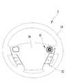
도 1은 본 발명의 일실시예에 따른 스티어링 휠 햅틱 유니트가 장착된 스티어링 휠에 대한 개략적인 평면도이다.
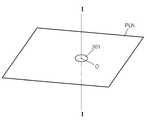
도 2는 본 발명의 일실시예에 따른 스티어링 휠 햅틱 유니트가 차량 스티어링 휠 전면에 장착된 상태에 대한 상태도이다.
도 3는 본 발명의 일실시예에 따른 스티어링 휠 햅틱 유니트에 대한 개략적인 사시도이다.
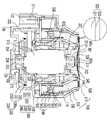
도 4은 본 발명의 일실시예에 따른 스티어링 휠 햅틱 유니트에 대한 개략적인 평면도이다.
도 5는 본 발명의 일실시예에 따른 스티어링 휠 햅틱 유니트에 대한 개략적인 단면도이다.
도 6는 본 발명의 일실시예에 따른 스티어링 휠 햅틱 유니트의 햅틱 노브에 대한 개략적인 단면도이다.
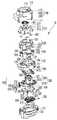
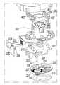
도 7는 본 발명의 일실시예에 따른 스티어링 휠 햅틱 유니트에 대한 개략적인 분해 사시도이다.
도 8은 본 발명의 일실시예에 따른 스티어링 휠 햅틱 유니트의 버튼 스위치부의 개략적인 사시도이다.
도 9은 본 발명의 일실시예에 따른 스티어링 휠 햅틱 유니트의 버튼 스위치부의 버튼 가이드 홀더 및 휠 하우징 바디의 개략적인 부분 확대 사시도이다.
도 10은 본 발명의 일실시예에 따른 스티어링 휠 햅틱 유니트의 의 개략적인 부분 확대 사시도이다.
도 11는 본 발명의 일실시예에 따른 스티어링 휠 햅틱 유니트의 부분 확대 저면 사시도이다.
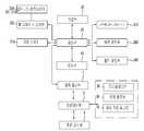
도 12은 본 발명의 일실시예에 따른 스티어링 휠 햅틱 유니트를 구비하는 스티어링 휠 햅틱 장치에 대한 개략적인 블록선도이다.
도 13은 본 발명의 일실시예에 따른 스티어링 휠 햅틱 유니트의 햅틱 노브의 로터리 동작을 나타내는 개략적인 상태 사시도이다.
도 14는 본 발명의 일실시예에 따른 스티어링 휠 햅틱 유니트의 버튼 스위치부의 동작을 나타내는 개략적인 상태 사시도이다.
도 15은 본 발명의 일실시예에 따른 스티어링 휠 햅틱 유니트의 샤프트 노브 홀더의 변형예에 대한 개략적인 사시도이다.
도 16는 본 발명의 일실시예에 따른 스티어링 휠 햅틱 유니트의 버튼 스위치부의 개략적인 부분 확대 사시도이다.
도 17는 본 발명의 일실시예에 따른 스티어링 휠 햅틱 유니트의 버튼 컬러 필터의 버튼 컬러 필터 바디의 개략적인 평면도이다.
도 18은 본 발명의 다른 일실시예에 따른 스티어링 휠 햅틱 유니트의 장착 상태를 나타내는 개략적인 배면도이다.
도 19는 본 발명의 다른 일실시예에 따른 스티어링 휠 햅틱 유니트의 차량 스티어링 휠 배면 측에 배치된 상태를 나타내는 개략적인 상태도이다.
도 20은 본 발명의 다른 일실시예에 따른 스티어링 휠 햅틱 유니트의 부분 확대 배면도이다.
도 21은 본 발명의 다른 일실시예에 따른 스티어링 휠 햅틱 유니트의 개략적인 부분 사시도이다.
도 22는 본 발명의 다른 일실시예에 따른 스티어링 휠 햅틱 유니트를 운전자가 조작하는 상태에서의 위치 관계를 나타내는 개략적인 상태도이다.
도 23은 본 발명의 다른 일실시예에 따른 스티어링 휠 햅틱 유니트의 스티어링 휠 광원부의 개략적인 부분 확대 사시도이다.
도 24은 본 발명의 또 다른 일실시예에 따른 스티어링 휠 햅틱 유니트를 구비하는 스티어링 휠 햅틱 장치의 개략적인 블록선도이다.
도 25는 본 발명의 다른 일실시예에 따른 스티어링 휠 햅틱 유니트의 스티어링 휠 광원부의 변형예의 개략적인 평면도이다.
도 26은 도 25의 도면 부호 B의 부분 확대 사시 단면도이다.1 is a schematic plan view of a steering wheel equipped with a steering wheel haptic unit according to an embodiment of the present invention.
2 is a state diagram of a state in which a steering wheel haptic unit according to an embodiment of the present invention is mounted on a front surface of a vehicle steering wheel.
3 is a schematic perspective view of a steering wheel haptic unit according to an embodiment of the present invention.
4 is a schematic plan view of a steering wheel haptic unit according to an embodiment of the present invention.
5 is a schematic cross-sectional view of a steering wheel haptic unit according to an embodiment of the present invention.
6 is a schematic cross-sectional view of a haptic knob of a steering wheel haptic unit according to an embodiment of the present invention.
7 is a schematic exploded perspective view of a steering wheel haptic unit according to an embodiment of the present invention.
8 is a schematic perspective view of a button switch unit of a steering wheel haptic unit according to an embodiment of the present invention.
9 is a schematic enlarged perspective view of a button guide holder and a wheel housing body of a button switch unit of a steering wheel haptic unit according to an embodiment of the present invention.
10 is a schematic partial enlarged perspective view of a steering wheel haptic unit according to an embodiment of the present invention.
11 is a partially enlarged bottom perspective view of a steering wheel haptic unit according to an embodiment of the present invention.
12 is a schematic block diagram of a steering wheel haptic device including a steering wheel haptic unit according to an embodiment of the present invention.
13 is a schematic perspective view illustrating a rotary operation of a haptic knob of a steering wheel haptic unit according to an embodiment of the present invention.
14 is a schematic perspective view illustrating the operation of a button switch unit of a steering wheel haptic unit according to an embodiment of the present invention.
15 is a schematic perspective view of a modification of the shaft knob holder of the steering wheel haptic unit according to the embodiment of the present invention.
16 is a schematic partially enlarged perspective view of a button switch unit of a steering wheel haptic unit according to an embodiment of the present invention.
17 is a schematic plan view of a button color filter body of a button color filter of a steering wheel haptic unit according to an embodiment of the present invention.
18 is a schematic rear view showing a mounting state of a steering wheel haptic unit according to another embodiment of the present invention.
19 is a schematic diagram showing a state in which the steering wheel haptic unit is disposed on the rear side of the vehicle steering wheel according to another embodiment of the present invention.
20 is a partially enlarged rear view of a steering wheel haptic unit according to another embodiment of the present invention.
21 is a schematic partial perspective view of a steering wheel haptic unit according to another embodiment of the present invention.
FIG. 22 is a schematic diagram showing a positional relationship in a state where a driver operates a steering wheel haptic unit according to another embodiment of the present invention. FIG.
23 is a schematic partial enlarged perspective view of a steering wheel light portion of a steering wheel haptic unit according to another embodiment of the present invention.
24 is a schematic block diagram of a steering wheel haptic device having a steering wheel haptic unit according to another embodiment of the present invention.
25 is a schematic plan view of a modified example of a steering wheel light portion of a steering wheel haptic unit according to another embodiment of the present invention.
26 is a cross-sectional view of a portion B of FIG.
이하에서는 스티어링 휠 햅틱 유니트 및 이를 구비하는 스티어링 휠 햅틱 장치에 대한 도면을 참조하여 설명하기로 한다.Hereinafter, a steering wheel haptic unit and a steering wheel haptic device having the same will be described with reference to the drawings.
도 1에는 본 발명의 일실시예에 따른 스티어링 휠 햅틱 유니트가 장착된 스티어링 휠에 대한 개략적인 평면도가 도시되고, 도 2에는 본 발명의 일실시예에 따른 스티어링 휠 햅틱 유니트가 차량 스티어링 휠 전면에 장착된 상태에 대한 상태도가 도시되고, 도 3에는 본 발명의 일실시예에 따른 스티어링 휠 햅틱 유니트에 대한 개략적인 사시도가 도시되고, 도 4에는 본 발명의 일실시예에 따른 스티어링 휠 햅틱 유니트에 대한 개략적인 평면도가 도시되고, 도 5에는 본 발명의 일실시예에 따른 스티어링 휠 햅틱 유니트에 대한 개략적인 단면도가 도시되고, 도 6에는 본 발명의 일실시예에 따른 스티어링 휠 햅틱 유니트의 햅틱 노브에 대한 개략적인 단면도가 도시되고, 도 7에는 본 발명의 일실시예에 따른 스티어링 휠 햅틱 유니트에 대한 개략적인 분해 사시도가 도시되고, 도 8에는 본 발명의 일실시예에 따른 스티어링 휠 햅틱 유니트의 버튼 스위치부의 개략적인 사시도가 도시되고, 도 9에는 본 발명의 일실시예에 따른 스티어링 휠 햅틱 유니트의 버튼 스위치부의 버튼 가이드 홀더 및 휠 하우징 바디의 개략적인 부분 확대 사시도가 도시되고, 도 10에는 본 발명의 일실시예에 따른 스티어링 휠 햅틱 유니트의 의 개략적인 부분 확대 사시도가 도시되고, 도 11에는 본 발명의 일실시예에 따른 스티어링 휠 햅틱 유니트의 부분 확대 저면 사시도가 도시되고, 도 12에는 본 발명의 일실시예에 따른 스티어링 휠 햅틱 유니트를 구비하는 스티어링 휠 햅틱 장치에 대한 개략적인 블록선도가 도시되고, 도 13에는 본 발명의 일실시예에 따른 스티어링 휠 햅틱 유니트의 햅틱 노브의 로터리 동작을 나타내는 개략적인 상태 사시도가 도시되고, 도 14에는 본 발명의 일실시예에 따른 스티어링 휠 햅틱 유니트의 버튼 스위치부의 동작을 나타내는 개략적인 상태 사시도가 도시되고, 도 15에는 본 발명의 일실시예에 따른 스티어링 휠 햅틱 유니트의 샤프트 노브 홀더의 변형예에 대한 개략적인 사시도가 도시되고, 도 16에는 본 발명의 일실시예에 따른 스티어링 휠 햅틱 유니트의 버튼 스위치부의 개략적인 부분 확대 사시도가 도시되고, 도 17에는 본 발명의 일실시예에 따른 스티어링 휠 햅틱 유니트의 버튼 컬러 필터의 버튼 컬러 필터 바디의 개략적인 평면도가 도시되고, 도 18에는 본 발명의 다른 일실시예에 따른 스티어링 휠 햅틱 유니트의 장착 상태를 나타내는 개략적인 배면도가 도시되고, 도 19에는 본 발명의 다른 일실시예에 따른 스티어링 휠 햅틱 유니트의 차량 스티어링 휠 배면 측에 배치된 상태를 나타내는 개략적인 상태도가 도시되고, 도 20에는 본 발명의 다른 일실시예에 따른 스티어링 휠 햅틱 유니트의 부분 확대 배면도가 도시되고, 도 21에는 본 발명의 다른 일실시예에 따른 스티어링 휠 햅틱 유니트의 개략적인 부분 사시도가 도시되고, 도 22에는 본 발명의 다른 일실시예에 따른 스티어링 휠 햅틱 유니트를 운전자가 조작하는 상태에서의 위치 관계를 나타내는 개략적인 상태도가 도시되고, 도 23에는 본 발명의 다른 일실시예에 따른 스티어링 휠 햅틱 유니트의 스티어링 휠 광원부의 개략적인 부분 확대 사시도가 도시되고, 도 24에는 본 발명의 또 다른 일실시예에 따른 스티어링 휠 햅틱 유니트를 구비하는 스티어링 휠 햅틱 장치의 개략적인 블록선도가 도시되고, 도 25에는 본 발명의 다른 일실시예에 따른 스티어링 휠 햅틱 유니트의 스티어링 휠 광원부의 변형예의 개략적인 평면도가 도시되고, 도 26에는 도 25의 도면 부호 B의 부분 확대 사시 단면도가 도시된다.FIG. 1 is a schematic plan view of a steering wheel equipped with a steering wheel haptic unit according to an embodiment of the present invention. FIG. 2 is a plan view of a steering wheel haptic unit according to an embodiment of the present invention. FIG. 3 is a schematic perspective view of a steering wheel haptic unit according to an embodiment of the present invention, and FIG. 4 is a sectional view of the steering wheel haptic unit according to an embodiment of the present invention. FIG. 5 is a schematic cross-sectional view of a steering wheel haptic unit according to an embodiment of the present invention, and FIG. 6 is a sectional view of the haptic knob of the steering wheel haptic unit according to an embodiment of the present invention. 7 is a schematic sectional view of a steering wheel haptic unit according to an embodiment of the present invention. 8 is a schematic perspective view of a button switch unit of a steering wheel haptic unit according to an embodiment of the present invention. FIG. 9 is a perspective view of a button switch unit of a steering wheel haptic unit according to an embodiment of the present invention. FIG. 10 is a schematic enlarged perspective view of a steering wheel haptic unit according to an embodiment of the present invention, and FIG. 11 is a perspective view of the steering wheel haptic unit according to an embodiment of the present invention. 12 is a schematic block diagram of a steering wheel haptic device including a steering wheel haptic unit according to an embodiment of the present invention, and FIG. 12 is a schematic block diagram of a steering wheel haptic device having a steering wheel haptic unit according to an embodiment of the present invention. 13 schematically shows the rotary operation of the haptic knob of the steering wheel haptic unit according to the embodiment of the present invention FIG. 14 is a schematic perspective view illustrating the operation of the button switch unit of the steering wheel haptic unit according to the embodiment of the present invention. FIG. 15 is a schematic perspective view of the steering wheel haptic unit according to the embodiment of the present invention, 16 is a schematic perspective view of a modified example of a shaft knob holder of a haptic unit, and FIG. 16 is a schematic partial enlarged perspective view of a button switch unit of a steering wheel haptic unit according to an embodiment of the present invention. FIG. 18 is a schematic plan view of a button color filter body of a button color filter of a steering wheel haptic unit according to an embodiment of the present invention. FIG. 18 is a schematic view showing a mounting state of a steering wheel haptic unit according to another embodiment of the present invention FIG. 19 is a side view of a steering wheel haptic unit according to another embodiment of the present invention. FIG. 20 is a partial enlarged rear view of the steering wheel haptic unit according to another embodiment of the present invention, and FIG. 21 is a schematic view showing the state of the steering wheel haptic unit according to another A schematic partial perspective view of a steering wheel haptic unit according to an embodiment is shown and FIG. 22 is a schematic diagram showing a positional relationship in a state where a driver operates the steering wheel haptic unit according to another embodiment of the present invention FIG. 23 is a schematic partial perspective view of a steering wheel light source unit of a steering wheel haptic unit according to another embodiment of the present invention, and FIG. 24 shows a steering wheel haptic unit according to another embodiment of the present invention. Fig. 25 is a schematic block diagram of a steering wheel haptic device having a steering wheel haptic device according to another embodiment A schematic plan view of a modified example of the steering wheel light portion of the steering wheel haptic unit according to the example is shown, and Fig. 26 is a partially enlarged perspective sectional view of the portion B of Fig.
본 발명의 일실시예에 따른 스티어링 휠 햅틱 유니트(10)는 차량의 스티어링 휠(2)에 장착되어 운전자로 하여금 보다 용이한 조작 및 햅틱감을 전달하고 경고 등의 물리적 경고 기능을 실행하여 운전자의 주의력 및 편의성 증대를 이룬다.The steering wheel
차량 스티어링 휠(2)은 휠 림(2A)과 휠 허브(2B,2C)를 포함할 수 있는데, 휠 림(2A)은 휠 허브 스포크(2C)를 통하여 휠 허브 바디(2B)와 연결된다. 본 실시예에서 휠 림은 링 타입을 이루었으나 운전자가 조향을 하기 위한 접촉 영역을 형성하는 범위에서 이에 국한되지 않고 다양한 구성이 가능하다.The
본 발명의 스티어링 휠 햅틱 유니트(10)는 차량 스티어링 휠의 전면 또는 배면 측에 배치된다. 즉, 도 1 및 도 2에 도시된 바와 같이 차량 스티어링 휠(2)의 전면에 스티어링 휠 햅틱 유니트(10)가 배치되거나, 도 18 및 도 19에 도시된 바와 같이 스티어링 휠 햅틱 유니트(10)는 스티어링 휠(2)의 배면 측에 배치된다. 먼저, 차량 스티어링 휠(2)의 전면에 배치되는 구조에 있어, 스티어링 휠 햅틱 유니트(10)는 휠 허브 바디(2B)에 배치되는데, 운전자의 간편한 조작을 이루도록 하는 썸휠(Thumb-wheel) 타입의 구조를 이루는 범위에서 다양한 배치가 가능하다. 스티어링 휠 햅틱 유니트(10)는 차량 스티어링 휠(2)의 전면 측에 배치되되, 차량 스티어링 휠(2)이 이루는 평면(PLN)에 대하여 스티어링 휠 햅틱 유니트(10)의 하기되는 햅틱 샤프트의 길이 방향, 궁극적으로 햅틱 노브가 회동 동작을 이루는 회동 중심축(I-I)이 교차되는 구조를 취함으로써 운전자가 엄지 손가락을 이용하여 원활한 회동 동작을 이루도록 할 수 있다.The steering wheel
보다 상세하게, 스티어링 휠 햅틱 유니트(10)는 햅틱 휠 하우징부(100)와 회로기판부(200)와 햅틱 휠 디바이스부(300)를 포함하는데, 회로기판부(200) 및 햅틱 휠 디바이스부(300)는 햅틱 휠 하우징부(100)에 안정적으로 장착된다.More specifically, the steering wheel
햅틱 휠 하우징부(100)는 차량 스티어링 휠(2), 보다 구체적으로 본 실시예에서 휠 허브 바디(2B)에 안정적으로 위치 고정되어 배치된다. 햅틱 휠 하우징부(10)는 휠 하우징 커버(110)와 휠 하우징 바디(120)와 휠 하우징 베이스(130)를 포함하는데, 휠 하우징 커버(110)와 휠 하우징 바디(120)와 휠 하우징 베이스(130)는 상호 체결되어 다른 구성요소들을 수용하기 위한 내부 공간을 형성한다.The haptic
휠 하우징 커버(110)에는 휠 하우징 커버 관통구(113)가 배치되는데, 휠 하우징 커버 관통구(113)를 통하여 하기되는 햅틱 휠 디바이스부(300)가 관통 배치된다. 휠 하우징 커버(110)의 단부측에는 휠 하우징 커버 장착부(111)가 배치되는데, 휠 하우징 커버 장착부(111)는 하기되는 휠 하우징 바디(120) 및/또는 휠 하우징 베이스(130)와 체결되는 구조를 형성한다.The wheel housing cover through
휠 하우징 커버(110)의 휠 하우징 커버 관통구(113)의 인근 내측에는 휠 하우징 커버 버튼 노브 가이드(115)가 배치되는데, 휠 하우징 커버 버튼 노브 가이드(115)는 하기되는 버튼 스위치부(500)의 버튼 노브(510)의 안정적인 수직 가동 상태를 형성하도록 한다.The wheel housing cover
휠 하우징 바디(120)는 휠 하우징 커버(110)와 접하도록 배치되는데, 휠 하우징 바디(120)는 휠 하우징 바디 관통구(123)를 구비한다. 휠 하우징 바디 관통구(123)는 휠 하우징 커버 관통구(113)와 연결되어 햅틱 휠 디바이스부(300)의 안정적인 연결 상태를 형성한다. 휠 하우징 바디(120)의 외측에는 휠 하우징 바디 장착부(121)가 배치되는데, 휠 하우징 바디 장착부(121)는 휠 하우징 커버 장착부(111)와 맞물림 체결되어 양자 간의 결합을 공고히 할 수 있다.The
휠 하우징 바디 관통구(123)의 외주에는 방사 방향으로 연장 형성되는 휠 하우징 바디 버튼 노브 격벽(124)이 배치되는데, 이는 하기되는 버튼 노브(510)의 안정적인 가동을 안내한다. 휠 하우징 바디 버튼 노브 격벽(124)은 복수 개가 구비될 수 있는데, 휠 하우징 바디 버튼 노브 격벽(124) 사이에는 휠 하우징 바디 버튼 노브 관통구(125)가 배치된다. 휠 하우징 바디 버튼 노브 관통구(125)에는 하기되는 버튼 스위치부(500)의 적어도 일부 구성요소가 관통 가능하게 배치된다. 휠 하우징 바디 버튼 노브 관통구(125)의 내측면에는 하기되는 버튼 가이드 홀더(540)의 안정적인 수직 가동을 안내하고 오조립을 방지하기 위한 휠 하우징 바디 버튼 홀더 가이드(126)가 배치된다. 또한, 휠 하우징 바디 버튼 노브 관통구(125)의 내측면에는 휠 하우징 바디 버튼 홀더 스톱퍼(127)가 배치되는데, 이는 버튼 노브(510)가 하기되는 버튼 스위치(550) 등을 통한 수직 복원력에 의하여 원치 않게 휠 하우징 바디 버튼 노브 관통구(125)로부터 분리 이탈되는 것을 방지할 수 있다.A wheel housing body button
휠 하우징 베이스(130)는 휠 하우징 바디(120)를 사이에 두고 휠 하우징 커버(110)와 마주하여 배치된다. 휠 하우징 베이스(130)의 외주에는 휠 하우징 베이스 장착부(131)가 배치되는데, 휠 하우징 베이스 장착부(131)는 휠 하우징 커버 장착부(111)와 체결되어 양자간의 결합을 공고히 한다.The
휠 하우징 베이스(130)에는 휠 하우징 베이스 커넥터(132)가 배치되는데, 휠 하우징 베이스 커넥터(132)에는 하기되는 회로기판부(200)로부터의 기판 커넥터 핀(211)이 배치되어 외부 전기 장치와의 전기적 접속을 이룰 수 있다. 여기서, 도면 부호 200의 구성요소에 대하여 회로기판이란 명칭이 부여되었으나, 회로 배선을 형성하는 범위에서 통상적인 인쇄회로기판으로 구현될 수도 있고, 인서트 사출 구조로 형성될 수도 있고, LED 등으로부터 발생되는 열을 외부로 방출하기 위한 메탈 기판으로 형성될 수도 있는 등 전기적 신호의 전달을 이루는 범위에서 다양한 구성이 가능하다.A wheel
회로기판부(200)는 햅틱 휠 하우징부(100)의 내부에 배치되는데, 회로기판부(200)는 단일의 기판으로 형성될 수도 있으나 본 실시예에서는 복수 개의 기판을 구비하는 구조를 취한다. 인쇄회로기판(200)는 다른 구성요소, 특히 하기되는 햅틱 휠 디바이스부(300)와 전기적으로 연결되어 햅틱 휠 디바이스 액츄에이터(310)의 햅틱 샤프트에 회동력을 제공하거나 또는 회동 상태를 감지하는 전기적 신호의 전달이 이루어질 수 있다.The
회로기판부(200)는 메인 기판(210)과 감지 기판(220)과 플렉서블 기판(230)과 노브 기판(240)을 구비한다. 메인 기판(210)은 휠 하우징 바디(120)와 휠 하우징 베이스(130)의 사이에 배치되고, 메인 기판(211)에는 커넥터 핀(211)이 배치되어 외부 전기 장치와의 전기적 소통을 이룰 수 있다. 메인 기판(211)의 중앙에는 메인 기판 관통구(213)가 배치되는데, 메인 기판 관통구(213)를 통하여 다른 구성요소, 즉 햅틱 휠 디바이스 액츄에이터(310)의 관통 배치를 가능하게 한다.The
감지 기판(220)에는 하기되는 햅틱 휠 디바이스부(300)의 햅틱 휠 디바이스 감지부(330)의 구성요소가 배치된다. 감지 기판(220)은 메인 기판(210)에 수직하게 배치되는데 이는 본 발명의 일실시예의 일예로서 본 발명의 감지 기판의 배치 구조가 이에 국한되지 않고 경우에 따라 메인 기판과 일체화될 수도 있는 등 다양한 변형이 가능하다. 본 실시예에서 감지 기판(220)은 햅틱 휠 디바이스부(300)의 햅틱 휠 디바이스 픽스처(320)의 픽스처 베이스(323)에 고정 장착되어 메인 기판(210)과 수직 배치되는 구조를 형성한다.Components of the haptic wheel
플렉서블 기판(230)은 수직 배치되는 구조의 메인 기판(210) 및 감지 기판(220) 간의 원활한 전기적 연결을 위하여 양단이 각각의 기판에 연결된다. 본 실시예에서 메인 기판(210)과 감지 기판(220)이 플렉서블 기판(230)을 통하여 연결되었으나, 메인 기판과 감지 기판이 직결되는 구조를 형성할 수 있다.Both ends of the
노브 기판(240)은 하기되는 햅틱 휠 디바이스부(300)의 햅틱 휠 디바이스 액츄에이터(310)의 상단측에 배치되고 노브 기판(240)에는 햅틱 노브 광원부(340)가 배치되는데, 이를 통하여 햅틱 노브(301)를 통한 광출력 기능이 실행될 수 있다.The
햅틱 휠 디바이스부(300)는 햅틱 휠 하우징부(100)에 배치되는데, 햅틱 휠 디바이스부(100)는 햅틱 휠 디바이스 액츄에이터(310)와 햅틱 휠 디바이스 픽스처(320)와 햅틱 휠 디바이스 감지부(330)를 포함한다. 햅틱 휠 디바이스 액츄에이터(310)는 회로기판부(200)와 전기적 연결 구조를 형성하여 이를 통한 전기적 신호를 내외부의 제어부 등으로부터 입력받아 저장부 등에 사전 설정된 방식에 따라, 조작자가 상기 햅틱 노브를 회전시키는 상태에 대응하여 또는 차량 상태 등의 경고 등을 위한 소정의 사전 설정되어 저장된 대응 방식에 따라 소정의 회전력 또는 충격력 또는 회전 저지력을 생성하여 조작자에게 역각을 제공한다. 본 실시예에서 햅틱 휠 디바이스 액츄에이터(310)는 전기 모터로 구현된다. 본 실시예에 따른 햅틱 휠 디바이스 액츄에이터(310)는 양축 전기 모터로 형성되는데, 양축은 햅틱 휠 디바이스 액츄에이터의 양단에 회전축이 배치되는 구조를 지시한다. 양축 전기 모터로 구현되는 햅틱 휠 디바이스 액츄에이터(310)의 햅틱 샤프트(311,313)에는 각각 햅틱 노브(301)와 햅틱 휠 디바이스 감지부(330)가 연결된다. 햅틱 샤프트(311,313)는 햅틱 휠 디바이스 액츄에이터(310)의 양단에 배치되는데, 햅틱 샤프트(311,313)는 샤프트 제 1 단부(311)와 샤프트 제 2 단부(313)를 포함한다. 샤프트 제 1 단부(311)는 햅틱 노브(301)와 연결되고, 샤프트 제 2 단부(313)는 하기되는 햅틱 휠 디바이스 감지부(330)와 연결된다.The haptic
햅틱 휠 디바이스 액츄에이터(310)는 햅틱 휠 디바이스 픽스처(320)에 의하여 햅틱 휠 하우징부(100)에 안정적으로 배치되고 하기되는 푸시 스위치부(400)의 푸시 스위치 가동부(420)와 함께 안정적인 수직 가동 운동을 이루도록 한다. 햅틱 휠 디바이스 픽스처(320)는 픽스처 바디(321)와 픽스처 베이스(323)를 포함하는데, 픽스처 바디(321)의 상단에는 픽스처 바디 관통구(326)가 배치되고 픽스처 베이스(323)의 하단에는 픽스처 베이스 관통구(324)가 배치된다. 양축 전기 모터 구조의 햅틱 휠 디바이스 액츄에이터(310)의 햅틱 샤프트(311,313)는 각각 픽스처 바디 관통구(326) 및 픽스처 베이스 관통구(324)를 통하여 각각 상하단으로 관통 배치된다. 픽스처 바디(321)와 픽스처 베이스(323)의 외주에는 각각 픽스처 장착부가 배치되고 이를 통하여 볼트와 같은 픽스처 체결부(328)가 배치되어 픽스처 바디(321)와 픽스처 베이스(323)의 체결 상태를 공고히 할 수 있다.The haptic
픽스처 바디(321)의 상단에는 픽스처 바디 노브 기판 안착부(327)가 형성되는데, 픽스처 바디 노브 기판 안착부(327)에는 회로기판부(200)의 노브 기판(240)이 배치되어 안정적인 위치 고정 상태를 이룰 수 있다. 픽스처 베이스(323)의 일측에는 픽스처 베이스 감지 장착부(325)가 배치되는데, 픽스처 베이스 감지 장착부(325)는 햅틱 휠 디바이스 감지부(330)의 서브 풀리 샤프트(336)의 회동 가능한 안정적인 장착 상태를 이루도록 한다.A fixture body knob
햅틱 노브(301)는 햅틱 샤프트(311)와 연결되고 햅틱 휠 하우징부(100)의 일면 상에 노출되도록 배치된다. 햅틱 노브(301)는 햅틱 휠 디바이스 액츄에이터(310)의 햅틱 샤프트(311)와 연결되는데 이들 사이에 샤프트 노브 홀더(312)가 배치될 수 있다. 샤프트 노브 홀더(312)는 햅틱 노브(301)와 햅틱 샤프트(311,313)의 샤프트 제 1 단부(311) 사이에 배치되는데, 샤프트 노브 홀더(312)를 통하여 햅틱 노브(301)와 햅틱 휠 디바이스 액츄에이터(310)의 햅틱 샤프트(311,313)의 샤프트 제 1 단부 사이의 원치 않는 상호 회동을 방지할 수 있다.The
샤프트 노브 홀더(312)와 샤프트 제 1 단부(311)는 억지 끼워 맞춤 구성을 취하고 샤프트 노브 홀더(312)의 외주는 챔퍼링된 다각형 구조를 이루어 접촉 영역 간의 상대 회동이 저지되는 구조를 취할 수 있다. 또한, 샤프트 노브 홀더(312a)는 이에 국한되지 않고 별도의 노브 스크류 등의 체결 수단을 통하여 샤프트 제 1 단부와 샤프트 노브 홀더 간의 체결 상태를 형성할 수도 있는 등 햅틱 노브와 햅틱 휠 디바이스 액츄에이터의 햅틱 샤프트 간의 상대 회동을 방지하는 구조를 취하는 범위에서 다양한 구성이 가능하다.The
햅틱 노브(301)는 햅틱 노브 플레이트(301a)와 햅틱 노브 바디(301b)를 구비하는데, 햅틱 노브 바디(301b)의 하부에는 햅틱 노브 바디 홈부(301c)가 구비되어 샤프트 노브 홀더(312)의 수용 배치를 가능하게 한다. 햅틱 노브 바디(301b)의 일면 상에는 햅틱 노브 플레이트(301a)가 배치되는데, 햅틱 노브 바디(301b)와 햅틱 노브 플레이트(301a)는 일체로 구현될 수 있다. 햅틱 노브 플레이트(301a)의 일면 상에는 하기되는 햅틱 노브 그립(301-2)이 형성되는데, 이를 통하여 사용자는 햅틱 노브(301)의 원활한 회전 동작, 즉 햅틱 휠 디바이스 액츄에이터(310)의 햅틱 샤프트(311,313)를 중심으로 하는 로터리 동작을 미끄럼없이 원활하게 수행할 수 있다.The
또한, 햅틱 노브(301)의 일면에는 햅틱 노브 딤플(301-1)이 형성된다. 햅틱 노브 딤플(301-1)은 요홈 형상으로 형성되는데, 햅틱 노브 딤플(301-1)은 중앙 영역을 향할수록 햅틱 노브(301)의 회전축의 방향으로 깊게 들어가는 구조를 취한다. 즉, 햅틱 노브 딤플(301-1)은 햅틱 노브(301)의 회전 중심에 수직한 방향으로의 딤플 깊이(d1,d2)가 햅틱 노브(301)의 중앙으로부터 반경 방향으로 향할수록 감소되는 구조를 이룬다. 즉, 도 6에 도시된 바와 같이, 햅틱 노브(301)의 중앙 영역에서의 햅틱 노브 딤플(301-1)의 깊이(d1)는 햅틱 노브(301)의 외곽 영역에서의 햅틱 노브 딤플(301-1)의 깊이(d2)보다 훨씬 큰 값을 갖도록 구성되어 운전자의 손가락, 특히 엄지 손가락을 이용하여 햅틱 노브(301)의 회전 동작을 실행함에 있어 보다 원활한 회전 동작을 이루도록 할 수 있다.In addition, a haptic knob dimple 301-1 is formed on one surface of the
이와 같은 구조를 통하여 운전자가 스티어링 휠(2)을 조정하면서 엄지 등의 손가락을 사용하여 회전 동작을 실행함에 있어 용이한 접촉 상태를 형성하여 햅틱 노브(301)의 원활한 로테이션 동작을 이루도록 할 수 있다. 즉, 햅틱 노브 딤플이 없거나 반구 형상으로 볼록하게 튀어나온 구조의 경우 엄지 손가락 등으로 햅틱 노브의 표면을 가압한 상태로 원활한 회전 동작을 이루기 어려운 반면, 본 구조의 햅틱 노브 딤플이 형성된 햅틱 노브는 엄지 손가락 등으로 표면 가압을 이룬 상태에서, 특히 다른 손가락으로 스티어링 휠의 휠 림을 그립한 상태에서도 보다 원활한 회전 동작을 이루도록 할 수 있다.Through such a structure, when the driver adjusts the
또한, 이 밖에도 햅틱 노브(301)에는 회전 동작을 원활하게 하도록 하는 구성요소가 더 구비될 수도 있다. 즉, 햅틱 노브(301)의 일면에는 햅틱 노브 그립(301-2)이 형성되는데, 햅틱 노브 그립(301-2)는 햅틱 노브(301)의 일면으로부터 돌출 형성된다. 이와 같은 햅틱 노브 그립(301-2)의 구성을 통하여 운전자가 엄지 등의 손가락을 이용하여 햅틱 노브(301)의 회전 동작을 이루는 경우 미끄럼없이 원활한 회동 상태를 유지할 수 있다.In addition, the
이러한 햅틱 노브(301)는 단일체로 구성될 수도 있으나 경우에 따라 햅틱 노브(301)를 통한 운전자의 조작을 보다 원활하게 하기 위한 이중 사출 구조를 형성할 수도 있다. 즉, 햅틱 노브(301)의 일면에는 운전자의 손가락 등의 피부와의 미끄럼이 덜한 재질로 형성되는 햅틱 노브 접촉면(301-3)이 형성되는 구조를 취할 수도 있다. 예를 들어, 햅틱 노브(301)는 도면 부호 301-4로 지시되는 부분은 일차적으로 폴리카보네이트(PC)와 같은 재질로 형성되고 그 일면에 폴리우레탄 등과 같은 열가소성 탄성체로 이중 사출되어 햅틱 노브 접촉면(301-3)이 부가적으로 형성되는 구조를 취할 수도 있다. 이러한 경우 운전자의 햅틱 노브 조작시 손가락 등의 땀 등에 의한 미끄럼을 방지하여 원활한 회동 동작을 이루도록 할 수 있다.The
햅틱 휠 디바이스 감지부(330)는 햅틱 샤프트(311,313)의 샤프트 제 2 단부(313)과 연결되어 햅틱 샤프트의 회전 상태, 즉 햅틱 휠 디바이스 액츄에이터(310)의 작동 상태를 감지한다. 햅틱 휠 디바이스 감지부(330)와 햅틱 휠 디바이스 액츄에이터의 샤프트 제 2 단부는 햅틱 휠 디바이스 감지부(330)와 연결되는데, 이들 간의 상대 회동을 방지하기 위하여 샤프트 제 2 단부와 햅틱 휠 디바이스 감지부(330) 사이에는 샤프트 감지 홀더(314)가 배치된다. 샤프트 감지 홀더(314)는 샤프트 제 1 단부와 햅틱 노브 간의 연결에 사용되는 샤프트 노브 홀더(312)에 대응되는 구성요소로서 이의 형상 및 구조는 샤프트 노브 홀더(312)의 기술과 중복되는바 구체적 사항은 상기로 대체한다.The haptic wheel
햅틱 휠 디바이스 감지부(330)는 본 실시예에서 광 검출기로 구현되는데, 햅틱 휠 디바이스 감지부(330)는 디바이스 감지 바디부(330a)와 디바이스 감지 센서부(339)를 포함하는데, 디바이스 감지 바디부(330a)는 햅틱 휠 디바이스 액츄에이터(310) 측과 연결되어 햅틱 샤프트의 회동 상태를 출력하고 디바이스 감지 센서부(319)는 디바이스 감지 바디부(330a)의 회동 상태를 검출한다. 본 실시예에서 디바이스 감지 바디부는 햅틱 샤프트의 회동 상태를 기계적으로 전달하기 위한 구조로 형성되고 디바이스 감지 센서부는 디바이스 감지 바디부의The haptic wheel
디바이스 감지 바디부(330a)는 디바이스 감지 메인 풀리(331)과 디바이스 감지 서브 풀리(335)와 디바이스 감지 벨트(333)와 디바이스 슬롯(337)을 포함한다. 디바이스 감지 메인 풀리(331)는 샤프트 감지 홀더(314)와 상대 회동 제한되도록 연결되어 햅틱 샤프트의 샤프트 제 2 단부(313)와 함께 회동한다. 디바이스 감지 메인 풀리(331)의 중앙에는 메인 풀리 장착부(332, 도 10 참조)가 배치되는데, 샤프트 감지 홀더(314)는 메인 풀리 장착부(332)에 삽입 수용된다. 디바이스 감지 메인 풀리(331)의 하단에는 디바이스 감지 메인 풀리(331)를 통한 햅틱 샤프트의 안정적인 가동을 이루고 정확한 역각 형성을 위한 구성요소로서 샤프트 관성체(315)가 배치된다. 샤프트 관성체(315)도 도너츠 타입으로 구성되어 디바이스 감지 메인 풀리(331)의 메인 풀리 장축부(332)의 외주에 삽입 배치된다. 경우에 따라 샤프트 관성체(315)와 디바이스 감지 메인 풀리(331)는 일체로 형성될 수도 있으나, 본 실시예에 따른 샤프트 관성체는 별개물로 형성되어 볼트와 같은 체결 부재를 통하여 디바이스 감지 메인 풀리(315)의 하단에 위치 고정되어 장착된다.The
디바이스 감지 서브 풀리(335)는 디바이스 감지 메인 풀리(331)와 이격되어 연결되고 디바이스 감지 벨트(333)는 디바이스 감지 메인 풀리(331)와 디바이스 감지 서브 풀리(335)를 연결하여 디바이스 감지 메인 풀리(331)의 기계적인 회동 상태를 디바이스 감지 서브 풀리(335)로 전달한다. 디바이스 슬롯(337)은 디바이스 감지 서브 풀리(335)에 동축 연결되는 구조를 취하는데, 디바이스 감지 서브 풀리(335)가 회동하는 경우 함께 회동한다. 디바이스 슬롯(337)은 서브 풀리 샤프트(336)에 의하여 회동 가능하게 지지된다. 서브 풀리 샤프트(336)는 햅틱 휠 디바이스 픽스처(320)의 픽스처 베이스(323)에 회동 가능하게 장착되는데, 픽스처 베이스(323)에는 픽스처 베이스 감지 장착부(325)가 형성되고 서브 풀리 샤프트(336)는 픽스처 베이스 감지 장착부(325)에 삽입 배치된다. 디바이스 감지 서브 풀리(335) 및 디바이스 슬롯(337)은 서브 풀리 샤프트(336)에 장착된다. 픽스처 베이스(323)와 디바이스 감지 서브 풀리(335) 간의 원활한 상태 회동을 위하여, 서브 풀리 샤프트(336)와 디바이스 감지 서브 풀리(335) 사이에는 서브 풀리 부싱(338)이 더 구비될 수도 있다.The device
디바이스 감지 센서부(339)는 디바이스 슬롯(337)에 인접하여 배치되는데, 디바이스 감지 센서부(339)는 감지 기판(220)에 배치된다. 디바이스 감지 센서부(339)는 광센서로 구현되는데, 디바이스 슬롯(337)은 디바이스 감지 센서부(339)의 발광부 및 수광부 사이에 배치되어 햅틱 샤프트의 샤프트 제 2 단부의 회동 상태는 디바이스 감지 메인 풀리, 디바이스 감지 벨트 및 디바이스 감지 서브 풀리 및 디바이스 슬롯을 거쳐 디바이스 감지 센서부로 하여금 광학 신호 변화를 통한 전기적 신호의 변화를 출력하도록 한다. 이러한 변화된 전기적 신호는 휠 하우징 베이스 커넥터(132)에 배치되는 커넥터 핀을 통하여 제어부와 같은 내외부 전기 장치로 전송될 수 있다.The device detecting
본 실시예에서 디바이스 감지 메인 풀리(331)와 디바이스 감지 서브 풀리의 회전비는 1이상의 값을 갖는 것이 바람직하다. 운전자의 손가락을 통하여 조작되는 햅틱 노브(301)가 1회전하는 동안, 즉 햅틱 노브(301)와 연결되어 동축 회전을 이루는 디바이스 감지 메인 풀리(331)가 1회전하는 동안 디바이스 감지 서브 풀리(335)는 수회 회전을 이룸으로써, 궁극적으로 햅틱 노브(301)의 1회전에 대한 디바이스 감지 센서부(339)를 통한 분해능을 증대시켜 햅틱 노브(301) 및 햅틱 샤프트의 보다 정확한 회전 상태 감지를 이룰 수 있다.In this embodiment, the rotation ratio of the device sensing
상기 실시예에서 햅틱 휠 디바이스 감지부는 풀리/벨트 구조를 취하는 것으로 기술되었으나, 햅틱 노브 내지 햅틱 샤프트의 정확한 회동 상태를 감지하는 범위에서 햅틱 휠 디바이스 감지부는 기어 전달 구조를 취할 수도 있는 등 다양한 구성이 가능하다. 기어 구조를 취하는 경우 햅틱 샤프트 측 기어와 햅틱 휠 디바이스 감지부의 디바이스 슬롯이 배치되는 기어는 직결될 수도 있고, 경우에 따라 이들 기어 사이에 하나 이상의 아이들 기어가 배치되어 연결되는 구조를 취할 수도 있다. 또한, 상기 실시예에서 햅틱 휠 디바이스 감지부는 광센서 구조로 이루어졌으나 햅틱 노브의 회전 상태를 감지하는 범위에서 다양한 구성이 가능하다.Although the haptic wheel device sensing unit is described as taking the pulley / belt structure in the above embodiment, the haptic wheel device sensing unit may take a gear transmission structure in a range that senses the accurate rotation state of the haptic knob or the haptic shaft, Do. In the case of taking the gear structure, the gear in which the device slots of the haptic-shaft-side gear and the haptic-wheel-device sensing portion are disposed may be directly connected, or may have a structure in which one or more idle gears are arranged and connected between these gears. In the above embodiment, the haptic wheel device sensing unit has the optical sensor structure. However, the haptic wheel device sensing unit may have various configurations in a range of sensing the rotation state of the haptic knob.
이와 같은 햅틱 노브, 햅틱 휠 디바이스 액츄에이터, 햅틱 휠 디바이스 감지부의 구성을 통하여 조작자의 의도가 담겨진 조작 상태가 햅틱 노브를 거쳐 햅틱 휠 디바이스 감지부에서 감지되고, 햅틱 휠 디바이스 감지부에서 감지한 조작 상태에 대응하여 또는 사전 설정된 방식을 따라 경고 등의 동작을 구현하기 위해 내외부 전기 장치로부터 전달되는 사전 설정된 방식을 따라, 양축 모터로 구현되는 햅틱 휠 디바이스 액츄에이터에서 생성되는 사전 설정된 역각 신호는 햅틱 노브를 거쳐 조작자에게 전달되어 조작자로 하여금 보다 안정적이고 정확한 촉각적 감지를 이루도록 할 수 있다. 이러한 햅틱 노브(301)는 차량 스티어링 휠(2)이 이루는 실질적인 평면 상에서 회동 동작을 이루는데, 햅틱 노브(301)는 상기한 바와 같이 햅틱 샤프트를 중심축으로 로터리 회동 동작을 이룬다. 이와 같은 로터리 동작을 통하여 사용자는 차량 스티어링 휠(2)의 휠 림(2A)을 통한 조향 상태 유지와 동시에 엄지 손가락을 통한 스티어링 휠 햅틱 유니트(10)의 조작이 가능한 썸-휠 방식 동작 구현을 가능하게 할 수 있다. 이는 운전자가 스위치 조작을 위하여 스티어링 휠, 보다 구체적으로 휠 림으로부터 손을 분리시키켜야 하는 등의 동작을 제거하여 휠림을 그립한 상태에서 운전자의 전방 주의력을 저해하지 않으면서도 햅틱 노브를 통한 원활한 사전 설정된 메뉴 선택과 같은 조작 기능을 증대시킬 수 있다. 예를 들어, 시소 동작 내지 힌지점을 중심으로 스크롤 동작을 이루는 종래의 구조를 디스플레이 장치와 연계하여 소정의 선택 메뉴를 화상 디스플레이시키는 장치의 구현에 있어, 운전자가 소정의 선택 동작을 이룸에 있어 선택 조작력을 조정하기 어려워 선택하고자 하는 메뉴를 지나치게 되는 문제점들이 수반되었으나, 본 구조에 따른 썸휠 구동 방식의 스티어링 휠 햅틱 유니트의 경우 시계 방향 또는 반시계 방향으로 엄지 손가락의 로터리 동작을 통하여 선택하고자 하는 메뉴를 신속하고 정확하게 선택 가능하며 이의 과정에서 보다 원활한 역각 제공을 이룰 수 있다는 장점이 수반된다. 또한, 이러한 스티어링 휠 햅틱 유니트의 로터리 동작에 연계되는 사용자 인터페이스의 다양한 제작을 가능하게 할 수도 있다.Through the configuration of the haptic knob, the haptic wheel device actuator, and the haptic wheel device sensing unit, the operation state including the intention of the operator is sensed by the haptic wheel device sensing unit via the haptic knob, A predetermined antagonistic signal generated in a haptic wheel device actuator implemented in a biaxial motor, according to a predetermined manner, transmitted from an internal or external electrical device to implement an operation, such as a warning, in response or in a predetermined manner, To allow the operator to perform more stable and accurate tactile sensing. The
한편, 본 발명에 따른 스티어링 휠 햅틱 유니트는 햅틱 노브를 통한 푸시 동작, 즉 차량 스티어링 휠이 이루는 평면에 수직한 방향인 길이 방향으로의 수직 가동을 가능하게 한다. 이와 같은 구조를 통하여 스티어링 휠 햅틱 유니트는 썸휠 구동 방식의 원활한 로터리 회동 동작과 푸시 동작을 통하여 보다 다양한 동작 구현을 이룰 수 있다. 스티어링 휠 햅틱 유니트의 수직 가동을 통한 스위칭 신호의 변화를 출력하기 위한 푸시 스위치부(500)가 더 구비될 수 있다. 푸시 스위치부(400)는 푸시 스위치(410)와 푸시 스위치 가동부(420)를 포함한다. 푸시 스위치(410)는 회로기판부(200)의 메인 기판(210)의 일면 상에 배치되는데, 본 실시예의 푸시 스위치(410)는 수직 가동되는 택트 스위치로 구현되나 메탈 돔 스위치로 구현될 수도 있는 등 수직 푸시 동작을 이루는 범위에서 다양한 구성이 가능하다. 푸시 스위치 가동부(420)는 햅틱 휠 디바이스 액츄에이터(310)와 함께 수직 가동되어 푸시 스위치(410)를 온/오프 절환시킨다. 푸시 스위치 가동부(420)는 푸시 스위치 가동 바디(421)와 푸시 스위치 가동 돌기(423)를 포함한다. 푸시 스위치 가동 바디(421)는 링 타입 구조를 취하는데, 푸시 스위치 가동 바디(421)의 중앙에는 푸시 스위치 가동 바디 관통구(422)가 구비되고 푸시 스위치 가동 바디 관통구(422)에는 햅틱 휠 디바이스 액츄에이터(310)의 외주에 배치되는 햅틱 휠 디바이스 픽스처(320)가 관통 배치된다. 푸시 스위치 가동 바디 관통구(422)의 내측에는 푸시 스위치 가동 장착부(424)가 배치되고 이의 대응되는 위치로 햅틱 휠 디바이스 픽스처(320)의 외주에는 픽스처 바디 푸시 스위치 가동 장착부(322)가 배치되는데, 푸시 스위치 가동 장착부(424)는 픽스처 바디 푸시 스위치 가동 장착부(322)에 맞물리어 푸시 스위치 가동 바디(421)와 햅틱 휠 디바이스 픽스처(320)의 안정적인 조립 공정을 이루도록 하고 장착 상태를 유지하도록 할 수 있다. 또한, 푸시 스위치 가동 바디의 외주에는 체결부가 구비되어 픽스처 바디와 픽스처 베이스의 체결시 함께 체결되는 구조를 취할 수도 있다.Meanwhile, the steering wheel haptic unit according to the present invention enables the push operation through the haptic knob, that is, the vertical movement in the longitudinal direction, which is perpendicular to the plane formed by the vehicle steering wheel. Through such a structure, the steering wheel haptic unit can realize more various operations through the smooth rotary turning operation and the push operation of the thumbwheel driving system. And a push switch unit 500 for outputting a change of the switching signal through the vertical movement of the steering wheel haptic unit. The
푸시 스위치 가동 돌기(423)는 푸시 스위치 가동 바디(421)의 외주에 배치되는데, 푸시 스위치 가동 돌기(423)는 푸시 스위치(410)와 직접적인 접촉 상태를 형성하고 푸시 스위치(410)의 초기 지지 상태를 통하여 푸시 스위치 가동 돌기(423), 푸시 스위치 가동 바디(421), 햅틱 휠 디바이스 픽스처(320), 햅틱 휠 디바이스 액츄에이터(310) 및 햅틱 노브(301)의 순차적인 연결 구조의 지지 상태를 일정하게 유지할 수 있고, 푸시 스위치(410)보다 큰 외력이 햅틱 노브(301)에 인가되는 경우 소정의 수직 가동 상태를 형성할 수 있다.The push switch
본 발명의 일실시예에 따른 푸시 스위치(410)는 복수 개가 구비되는데, 복수 개의 푸시 스위치(410)의 개수에 대응하여 푸시 스위치 가동 돌기(423)도 복수 개가 구비된다. 본 실시예에서는 4개로 구현되는 복수 개의 푸시 스위치(410) 및 푸시 스위치 가동 돌기(423)를 통하여 햅틱 휠 디바이스 액츄에이터(310) 및 햅틱 노브(301)는 푸시 스위치(310)를 통한 안정적인 지지 상태를 형성할 수 있다.A plurality of push switches 410 according to an embodiment of the present invention are provided, and a plurality of push switch
외력이 가해지지 않는 평시의 경우 햅틱 휠 디바이스 액츄에이터(310)는 푸시 스위치(410)에 의하여 안정적인 수직 지지 상태를 형성하나, 운전자와 같은 사용자가 햅틱 노브(301)를 사전 설정된 값 이상의 크기로 수직 가압하는 경우, 햅틱 노브(301), 햅틱 휠 디바이스 액츄에이터(310), 햅틱 휠 디바이스 픽스처(320), 푸시 스위치 가동부(420)를 거쳐 푸시 스위치(410)의 전기적 신호의 변화가 발생한다. 본 실시예의 푸시 스위치(410)는 4개가 구비되는데, 햅틱 노브(301)의 가압 방향에 따라 개별적인 스위칭 절환 동작을 이룰 수도 있다. 예를 들어, 햅틱 노브(301)의 평면도 상 우측 상단을 가압하는 경우 소정의 영역만 가압되어 전체적으로 볼 때 햅틱 휠 디바이스 액츄에이터(310)는 일단측만이 하방 이동을 이루는 틸팅 동작을 구현할 수도 있다. 반면, 햅틱 휠 디바이스 액츄에이터(310)와 연결되는 햅틱 노브(301)의 중앙 영역을 수평을 이루며 수직 가압하는 경우 전체적인 수직 가압 동작을 이루어 4개의 푸시 스위치가 가동되는 신호를 형성할 수도 있다. 경우에 따라, 햅틱 노브(301)의 중심, 즉 햅틱 휠 디바이스 액츄에이터(310)의 중심축을 기준으로 대각 배치되는 푸시 스위치가 동시에 또는 일정 시간 내 연속적으로 가압되는 경우 개별 틸팅 동작이 아닌 전체 수직 가압 동작으로 인식되도록 하는 구조를 취할 수도 있다.The haptic
한편, 푸시 스위치부(400)의 푸시 스위치(410)는 메인 기판(210) 상에 배치되어 위치 고정되는 구조를 취하고 푸시 스위치 가동부(420)만이 햅틱 휠 디바이스 액츄에이터(310)와 함께 수직 가동되는 구조를 취하는 반면, 상기한 햅틱 휠 디바이스 감지부(330)는 햅틱 휠 디바이스 액츄에이터와 함께 수직 가동되는 구조를 취할 수도 있다. 햅틱 휠 디바이스 액츄에이터(310)가 배치되는 햅틱 휠 디바이스 픽스처(320)의 픽스처 베이스(323)에 감지 기판(220)이 위치 고정되어 배치되고 디바이스 감지 바디부의 디바이스 감지 메인 풀리는 햅틱 샤프트와, 그리고 디바이스 감지 서브 풀리는 픽스처 베이스에 연결됨으로써, 궁극적으로 디바이스 감지 센서부 및 디바이스 감지 바디부는 햅틱 휠 디바이스부와 함께 수직 가동되는 구조를 형성한다. 이와 같은 구조를 통하여 푸시 동작을 이루는 푸시 스위치부 및 로터리 동작을 이루는 햅틱 휠 디바이스부와의 연결이 궁극적으로 햅틱 노브를 통하여 이루어지는 구조를 형성함으로써, 푸시 수직 가동 및 로터리 회동 동작의 일체화를 통하여 운전자 등의 조작자로 하여금 우수한 조작감을 제공할 수 있고, 안정적이면서도 틸팅 기능도 동시에 이룰 수 있는 등 다변화된 동작을 구현할 수 있다.The
상기와 같은 로터리 회동 동작 및 푸시/틸팅 동작을 이룸과 동시에 각각의 기능 수행시 빛의 출력을 통한 시각적 인지를 향상시키기 위한 구성이 더 구비될 수도 있다. 본 발명의 햅틱 휠 디바이스부(300)는 햅틱 노브 광원부(340)를 포함할 수 있는데, 햅틱 노브 광원부(340, 도 15 참조)는 본 실시예에서 회로기판부(200)의 노브 기판(240)에 배치된다. 노브 기판(240)은 햅틱 휠 디바이스 액츄에이터(310)의 단부로 샤프트 제 1 단부(311)가 관통 배치되도록 햅틱 휠 디바이스 액츄에이터(310)의 상단에 배치되는데, 보다 구체적으로 픽스처 바디(321)의 상단에는 픽스처 바디 노브 기판 안착부(327)가 배치된다. 픽스처 바디 노브 기판 안착부(327, 도 5 참조)에 노브 기판(240)이 수용 배치되는데, 노브 기판(240)은 별도의 라인을 통하여 메인 기판(210)과 전기적 연결 구조를 형성할 수 있다. 노브 기판(240)의 일면 상에는 햅틱 노브 광원부(340)가 배치되는데, 햅틱 노브 광원부(340)는 LED와 같은 광원으로 구현된다. 햅틱 노브(301)는 폴리카보네이트(PC)와 같은 투광 재료로 형성되어 노브 기판(240) 상의 햅틱 노브 광원부(340)로부터 출사되는 빛을 외부로 원활하게 전달할 수 있다. 햅틱 노브 광원부(340)는 복수 개가 구비될 수 있는데, 본 발명에 따른 햅틱 노브 광원부(340)는 청색,녹색,적색의 빛을 출사하는 LED가 균등하게 각분할되어 배치되거나 다색 출력 가능하도록 단일화된 모듈이 하나 이상이 배치되고 각각의 LED로 구현되는 햅틱 노브 광원부(340)로부터 출력되는 빛은 햅틱 노브 바디(301b)의 하면을 통하여 외부로 투광 및/또는 도광되어 외부로 출사된다. 이러한 햅틱 노브 광원부(340)의 작동 상태는 사전 설정된 방식, 예를 들어 소정의 주기마다 깜박이거나 또는 일정하게 변화되는 신호 주기로 출력되거나 소정의 색상이 동시에 출력되어 합성된 색상을 출력하도록 하는 등 사전 설정된 제어 방식에 따라 다양한 색상 내지 크기 내지 주기의 빛을 외부로 출력함으로써 운전자와 같은 사용자로 하여금 스티어링 휠 햅틱 유니트의 작동 상태 내지 사용자에 의하여 선택된 조작 상태 등을 신속하게 시각적으로 인지할 수 있다.
It is also possible to provide a rotary turning operation and a push / tilting operation as described above and a configuration for improving visual perception by outputting light when each function is performed. The haptic
또 한편, 본 발명에 따른 스티어링 휠 햅틱 유니트(10)는 버튼 스위치부(500)를 구비하여, 햅틱 휠 디바이스부와 함께 복합 조작 기능을 실행할 수 있다. 버튼 스위치부(500)는 햅틱 노브(301)의 외곽에 배치되는데, 햅틱 노브(301)를 통한 햅틱 휠 디바이스 액츄에이터 내지 푸시 스위치부와는 별개의 독립적인 수직 가동 동작을 이루어 소정의 변화된 스위칭 신호를 생성할 수 있다. 본 발명의 실시예에 따른 버튼 스위치부(500)는 햅틱 노브(301)를 중심으로 외곽을 둘러싸는 구성을 취하는데, 버튼 스위치부(500)는 버튼 노브(510)와 버튼 가이드(530)와 버튼 홀더(540)와 버튼 스위치(550)를 포함한다. 버튼 노브(510)는 일면이 햅틱 휠 하우징부(100)의 외부로 노출되도록 햅틱 노브(301)의 외곽에 배치된다. 버튼 노브(510)는 버튼 노브 헤드(511)와 버튼 노브 바디(513)를 포함하는데, 버튼 노브 헤드(511)는 햅틱 노브(301)의 외곽에 노출되어 배치되고 버튼 노브 바디(513)는 버튼 노브 헤드(511)의 하단에 배치된다. 버튼 노브 헤드(511)와 버튼 노브 바디(513)는 별개물로 구성될 수도 있으나 본 실시예에서는 일체로 형성되는 구조를 취한다.In addition, the steering wheel
버튼 노브 헤드(511)의 일면을 통하여 버튼 노브 아이콘(512)이 표시될 수 있는데, 버튼 노브 아이콘(512)은 버튼 노브 헤드(512)의 일면 상에 직접 형성될 수도 있고, 경우에 따라 버튼 노브 헤드(512)는 폴리카보네이트와 같은 투명 재료로 형성되고 하부에 배치되는 하기되는 바와 같은 별도의 표시 소자를 통하여 출력되는 구조를 취할 수도 있다.A
버튼 노브 헤드(511)와 버튼 노브 바디(513)는 내부에 공간을 구비하는 구성을 취하여, 버튼 노브 헤드(511)와 버튼 노브 바디(513)가 취하는 공간에 버튼 가이드(530)가 배치될 수 있다. 버튼 가이드(530)는 일단이 버튼 노브(510)의 내부에 배치되고 타단이 상기 햅틱 휠 하우징부(100)의 내부로 회로기판부(200)를 향하여 배치된다. 즉, 버튼 가이드(530)는 일단이 버튼 노브 헤드(511)와 버튼 노브 바디(513)가 이루는 내부 공간에 배치되고 타단이 메인 기판(210)을 향하도록 배치된다. 버튼 가이드(530)는 버튼 가이드 헤드(531)와 버튼 가이드 바디(533)를 포함한다. 버튼 가이드 헤드(531)와 버튼 가이드 바디(533)는 본 실시예에서 일체로 구성되었으나 별개로 구성될 수도 있다. 버튼 가이드 헤드(531)의 일단에는 버튼 가이드 바디(533)가 연결되는데, 버튼 가이드 헤드(531)의 상단은 버튼 노브 헤드(511) 및 버튼 노브 바디(513)가 이루는 내부 공간에 삽입 배치되고 버튼 가이드 바디(533)의 단부는 버튼 스위치(550)가 배치되는 메인 기판(210)을 향하도록 위치하여 하기되는 버튼 가이드 홀더(540)의 내부에 배치된다. 버튼 가이드(530)는 투명 내지는 소정 색상의 도광 재료로 형성되는데, 버튼 가이드 바디(533)의 단부를 통하여 유입되는 빛은 버튼 가이드 헤드(531)의 일면으로 통하여 외부로 전달된다. 버튼 가이드 바디(533)의 측면에는 버튼 가이드 바디 장착부(535)가 배치되는데, 버튼 가이드 바디 장착부(535)의 대응하는 위치로 버튼 가이드 홀더(540)의 측면에는 홀더 장착부(544)가 배치되고 버튼 가이드 바디 장착부(535)와 홀더 장착부(544)는 서로 맞물리어 체결되는 구조를 형성한다. 버튼 가이드 바디(533)의 외주면에는 버튼 가이드 바디 그루브(534)가 구비되는데, 버튼 가이드 바디 그루브(534)는 버튼 가이드 홀더(540)에 형성되는 홀더 수용부 그루브(542)와 맞물리어 버튼 가이드(530)와 버튼 가이드 홀더(540) 간의 원활한 상대 장착 구조를 형성하여 햅틱 휠 하우징부(100)에의 원활한 장착 및 조립시 오조립 가능성을 방지할 수 있다.The
버튼 가이드 홀더(540)는 버튼 가이드(530)에 부착되어 버튼 가이드(530)와 함께 햅틱 휠 하우징부(100), 보다 구체적으로 휠 하우징 바디(120)에 안정적으로 수직 가동 가능하게 배치된다. 버튼 가이드 홀더(540)는 휠 하우징 바디(120)의 일면 상에 형성되는 휠 하우징 버튼 노브 관통구(125)에 수직 가동 가능하게 삽입되는데, 버튼 가이드 홀더(540)의 외주면에는 길이 방향을 따라 형성되는 버튼 가이드 홀더 라인(546)이 배치된다. 버튼 가이드 홀더 라인(546)의 대응되는 위치로 휠 하우징 버튼 노브 관통구(125)의 내주에는 휠 하우징 바디 버튼 홀더 가이드(126)가 배치되는데, 버튼 가이드 홀더 라인(546)과 휠 하우징 바디 버튼 홀더 가이드(126)는 수직 가동 가능하게 맞물림되는 구조를 취한다.The
버튼 가이드 홀더(540)에는 버튼 가이드 홀더 가동부(543)이 배치되는데, 버튼 가이드 홀더 가동부(543)는 버튼 가이드 홀더(540)의 중앙에 형성된 버튼 가이드 홀더 수용부(541)의 내측 하단으로부터 연장 형성되어 하부에 배치되는 버튼 스위치(550)와 상시 접촉 상태를 유지하도록 형성된다. 즉, 버튼 가이드 홀더(540), 버튼 가이드(530), 버튼 노브(510)는 별도의 지지 수단을 통하여 지지되는 구조를 취할 수도 있으나, 본 실시예에서는 순차적으로 버튼 스위치(550)에 의하여 지지되는 구조를 취한다.The button guide
이와 같은 구조를 통하여, 운전자 등의 사용자에 의하여 버튼 노브(510)에 가해지는 압력은 버튼 가이드(530), 버튼 가이드 홀더(540)를 거쳐 버튼 스위치(550)로 전달된다. 여기서, 버튼 가이드 홀더 가동부(543)는 버튼 가이드 홀더(540)의 버튼 가이드 홀더 수용부(541)의 내측면으로부터 연장 형성되어 하부를 향하는 구조를 취하는데, 버튼 가이드 홀더 가동부(543)의 상면에는 버튼 가이드 홀더 가동부 안착면(547)이 형성되어 버튼 가이드 바디 걸림부(536)의 걸림 안착 상태를 형성하도록 한다. 즉, 버튼 가이드(530)의 하단은 분기되는 두 개의 버튼 가이드 브랜치(537)가 형성되고 중앙에는 버튼 가이드 바디 걸림부(536)이 형성되는데, 버튼 가이드 바디 걸림부(536)는 버튼 가이드 홀더 가동부 안착면(547)과 접하여 안정적인 장착 구조를 형성한다. 버튼 가이드 브랜치(537)는 버튼 가이드 바디(530)의 하단으로부터 양측으로 분기되는데, 이는 버튼 스위치(550)의 측부에 배치되는 버튼 광원부(560)로부터의 빛의 상부로 전달하기 위한 구조를 형성할 수 있다. 버튼 광원부(560)는 LED 등의 광원으로 구현되는데, 버튼 광원부(560)는 각각의 버튼 가이드에 대하여 복수 개가 배치됨으로써 버튼 가이드 브랜치에 개별 할당되는 구조를 취할 수도 있다. 버튼 가이드(530)는 폴리카보네이트와 같은 투명 도광 재료로 형성될 수도 있고 소정의 사전 설정된 색상을 구비하는 구조를 취할 수도 있다.Through this structure, the pressure applied to the
또한, 버튼 스위치부(500)에는 버튼 광원부로부터 출사되는 빛을 이용하여 다양한 아이콘을 형성할 수 있는 표시 소자를 더 구비할 수도 있다. 이와 동시에 버튼 광원부는 각각의 버튼 가이드 내지 버튼 컬러 필터에 대하여 복수 개의 색상의 빛을 출력하는 구조를 취한다. 버튼 스위치부(500)는 버튼 컬러 필터(520)를 더 포함할 수 있는데, 버튼 컬러 필터(520)는 버튼 컬러 필터 베이스(521)와 버튼 컬러 필터 바디(523)를 포함한다. 버튼 컬러 필터 베이스(521)는 도광 재료로 형성되어 버튼 컬러 필터 베이스(521)의 하면을 통하여 유입되는 빛을 전면에 고르게 분사시키는 기능을 수행한다. 버튼 컬러 필터 바디(523)는 복수 개의 색상의 빛을 출력하는 버튼 광원부로부터의 제 1 색상광을 출사시키는 제 1 투과 영역(523a)과, 버튼 광원부로부터의 다른 제 2 색상광을 출사시키는 제 2 투과 영역(523b)과, 제 1 투과 영역과 제 2 투과 영역이 교차되는 교차 영역(523c)과, 제 1 색상과 및 제 2 색상광을 모두 차단하는 차단 영역(523d)를 포함하는데, 교차 영역(523c)은 제 1 투과 영역(523a) 및 제 2 투과 영역(523c)와 함께 각각 제 1 버튼 아이콘(512a) 및 제 2 버튼 아이콘(512b)를 형성할 수 있다. 예를 들어 버튼 광원부는 적색 LED와 청색 LED를 포함할 수 있고, 제 1 투과 영역은 적색광을 출사시키고 제 2 투과 영역은 청색 광을 출사시키는 구조를 취함으로써 제 1 투과 영역, 제 2 투과 영역 및 교차 영역 등을 통하여 소정의 "USER SET" 또는 "
The button switch unit 500 may further include a display device capable of forming various icons by using light emitted from the button light source unit. At the same time, the button light source unit has a structure of outputting light of a plurality of colors to each button guide or button color filter. The button switch unit 500 may further include a
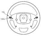
상기 실시예에서는 스티어링 휠 햅틱 유니트가 차량 스티어링 휠의 전면 측에 배치되는 구조에 대하여 기술되었으나, 본 발명의 다른 실시예로서의 스티어링 휠 햅틱 유니트(10s)는 차량 스티어링 휠(2)의 배면 측에도 배치될 수 있다. 즉, 도 18 및 도 19에 도시된 바와 같이 스티어링 휠 햅틱 유니트(10s)는 스티어링 휠(2)의 배면 측에 배치되는데, 도 19에 도시된 바와 같이 스티어링 휠 햅틱 유니트(10s)의 햅틱 샤프트의 회전 중심축, 궁극적으로 스티어링 휠 햅틱 유니트(10s)의 햅틱 노브(301s)의 회전 중심축(II-II)이 차량 스티어링 휠(2)이 회동을 이루는 평면(PLN)에 평행하게 배치되는 구조를 이룸으로써, 운전자는 검지, 중지 등의 가급적 엄지 손가락 이외의 손가락을 이용하여 보다 원활하게 스티어링 휠 햅틱 유니트(10s)를 가동시키고 촉각적 전달을 수행할 수도 있다.Although the steering wheel haptic unit is disposed on the front side of the vehicle steering wheel in the above embodiment, the steering wheel
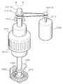
스티어링 휠 햅틱 유니트(10s)는 도 21에 도시된 바와 같이, 햅틱 휠 하우징부(100s)와 회로기판부와 햅틱 휠 디바이스(300s)를 구비하는데, 햅틱 휠 하우징부(100s)는 차량 스티어링 휠의 휠 바디와 일체화된 구조를 형성하고 회로기판부가 이에 내장되는 구조를 취할 수도 있는 등 다양한 변형이 가능한바, 본 실시예에서는 햅틱 휠 디바이스(300s)를 중심으로 설명한다. 햅틱 휠 디바이스부(300s)는 햅틱 샤프트(311s)를 구비하는 햅틱 휠 디바이스 액츄에이터(310s)와, 햅틱 샤프트(311s)와 연결되고 외부로 노출되는 햅틱 노브(301s)와, 햅틱 샤프트(311s)의 회동 상태를 감지하는 햅틱 휠 디바이스 감지부(330s)를 포함한다. 햅틱 휠 디바이스 액츄에이터(310s)는 전기 모터로 구현될 수 있는데, 햅틱 휠 디바이스 액츄에이터(310s)와 햅틱 노브(301s)는 햅틱 전달부(310-1s,310-2s,310-3s)을 통하여 연결된다. 즉, 햅틱 샤프트(311s)의 단부에는 햅틱 전달 풀리(310-1s)가 배치되고, 햅틱 노브(301s)의 햅틱 노브 바디(301-1s)의 단부(301-2s)에는 햅틱 연결 풀리(310-3s)가 배치되고 햅틱 전달 풀리(301-s)와 햅틱 연결 풀리(310-3s)는 햅틱 전달 벨트(310-2s)를 통하여 연결되어 햅틱 휠 디바이스 액츄에이터(310s)로부터의 동력을 전달받아 소정의 햅틱 기능을 햅틱 노브로 전달할 수 있다. 여기서, 햅틱 노브로의 동력 전달은 풀리 구조를 통하여 이루어지는 것으로 기술되었으나 기어 동력 전달 구조를 취할 수도 있고 햅틱 휠 디바이스 액츄에이터와 햅틱 노브가 직결되는 구조를 취할 수도 있는 등 다양한 변형이 가능하다.21, the steering wheel
여기서, 햅틱 노브(301s)는 햅틱 휠 하우징부(미도시)의 내부에 배치되는데, 햅틱 휠 하우징부로부터 연장 형성되는 햅틱 노브 가이드(101s,102s)를 통하여 안정적인 회동을 이루기 위한 지지 구조를 더 구비할 수도 있다.Here, the
햅틱 휠 디바이스 감지부(330s)는 햅틱 노브(301s)와 연결된다. 즉, 햅틱 휠 디바이스 감지부(330s) 디바이스 감지 슬롯(397s)과 디바이스 감지 센서부(339s)를 구비하는데, 디바이스 감지 슬롯(397s)은 햅틱 노브(301s)에 동축 연결될 수 있고, 디바이스 감지 센서부(339s)은 디바이스 감지 슬롯(397s)에 인접하여 배치되는 광센서로 구현될 수 있고 경우에 따라 자기 센서로 구현될 수도 있다. 디바이스 감지 센서부(339s)는 회로기판부의 감지 기판(220s)에 배치된다. 이와 같은 구조를 통하여 소정의 햅틱 동작 구현 및 운전자에 의하여 조작되는 햅틱 노브를 통한 햅틱 노브 회동 동작을 감지함으로써 소정의 스위칭 기능과 동시에 정확한 역각 정보를 제공할 수 있다.The haptic wheel device sensing unit 330s is connected to the
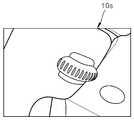
도 22에는 본 발명의 다른 실시예에 따라 차량 스티어링 휠(2)의 배면 측에 배치되는 스티어링 휠 햅틱 유니트의 운전자를 통한 작동 상태가 도시되는데, 통상적으로 소정의 스위칭 동작은 커브 등의 곡선 주로를 주행하는 과정에서 이루어지기 보다는 직진 주행 상태에서 이루어지는 비중이 높은바, 직진 주행 중 운전자는 차량 스티어링 휠(2)의 휠 림(2A)을 그립한 상태에서 중지 등의 손가락을 활용하여 햅틱 노브(301s)를 조작할 수 있고, 햅틱 노브(301s)를 통한 소정의 역각 정보를 원활하게 전달받을 수도 있다. 이와 같이, 햅틱 노브(301s)는 차량 스티어링 휠(2)의 배면 측에 배치되되, 차량 스티어링 휠의 휠 림(2A)으로부터 사전 설정 거리 이내에 이격 배치되는데, 본 실시예에서 사전 설정 거리는 예를 들어 5cm 내지 20cm로 실행되으나, 사전 설정 거리는 운전자의 엄지 손가락 이외의 손가락으로 차량 스티어링 휠(2)의 휠 림(2A)을 그립한 상태에서 원활한 조작을 가능하게 하는 거리가 선택되는 것이 바람직하다. 또한, 스티어링 휠의 회전 선회 동작 여부는 스티어링 앵글 센서(미도시)로부터의 신호를 활용하여, 스티어링 휠의 선회 회전 동작 중 발생하는 햅틱 노브의 원치 않는 접촉과 운전자의 의도에 따른 회동 여부를 판별하여 스티어링 휠 햅틱 유니트의 동작을 제어할 수도 있다.22 shows an operation state of the steering wheel haptic unit disposed on the rear side of the
또 한편, 본 발명의 스티어링 휠 햅틱 유니트(10)는 햅틱 노브 내지 버튼 노브 이외의 영역에 스위칭 동작에 대응하는 빛을 출력하거나 차량의 사전 설정된 경고 상태로 차량 상태가 진입하는 경우 이를 운전자에게 빛을 출력하기 위하여 별도의 광원부를 더 구비할 수도 있다. 즉, 본 발명의 스티어링 휠 햅틱 유니트(10)는 스티어링 휠 광원부(4B,5B)를 구비하는데, 스티어링 휠 광원부(4B,5B)는 차량 스티어링 휠(2)에 배치된다. 보다 구체적으로, 도 23에 도시된 바와 같이, 스티어링 휠 광원부(4B,5B)는 휠 허브 바디(2B)와 휠 스포크(2C) 사이에 배치된다. 스티어링 휠 광원부(4B,5B)는 스티어링 휠 광원(4B)과 스티어링 휠 광전달부(5B)를 구비하는데, 스티어링 휠 광원(4B)은 LED 등의 광원으로 구현된다. 본 실시예에서 스티어링 휠 광원(4B)은 휠 허브 바디(2B) 측에 배치되는데, 휠 허브 바디(2B)의 휠 허브 바디 수용부(2B-1)에는 스티어링 휠 광원 기판(3B)이 배치되고 스티어링 휠 광원(4B)은 스티어링 휠 광원 기판(3B)의 일면 상에 배치된다. 스티어링 휠 광원 기판(3B) 상의 스티어링 휠 광원(4B)의 개수 및 출력 색상 등의 다양한 구성이 가능하다. 스티어링 휠 광전달부(5B)는 도광체로 구현될 수 있는데, 스티어링 휠 광전달부(5B)는 스티어링 휠 광전달 바디(5B-1)와 스티어링 휠 광전달 입력부(5B-2)를 포함한다. 스티어링 휠 광전달 입력부(5B-2)를 통하여 스티어링 휠 광원(4B)으로부터 출사된 빛이 스티어링 휠 광전달 바디(5B-1)를 통하여 외부로 출력된다. 이와 같은 광출력 기능을 통하여 운전자는 신속한 광 신호 인지를 이룸으로써 출력 신호에 원활하게 대처할 수 있다. 이러한 스티어링 휠 광원부를 통하여 출력되는 빛은 햅틱 노브의 회전 동작에 대응하는 사전 설정된 빛을 출력할 수도 있고, 경우에 따라 외부의 차량 제어 장치로부터 전달되는 전기적 신호에 따른 출력, 예를 들어 주차 브레이크의 미 해제, 차량 도어의 열림, 트렁크 열림, ABS 고장, 차량 배터리의 방전 내지는 전기 자동차의 충전량 저하 상태 경고, 엔진 오일 압력 경고, 타이어 저압 내지 고압 상태 경고, 안전벨트 미착용 상태 경고, 엔진 체크 경고 등과 같이 운전자에게 소정의 경고 내지 안내 기능을 실행하여야 하는 경우 스티어링 휠 광원부를 통한 소정의 광 출력 기능을 실행함으로써 운전자로 하여금 신속한 인지 및 이를 통한 대응 상태를 이루도록 할 수 있다.In addition, the steering wheel
이러한 경고는 햅틱 기능과 개별적으로 내지는 동시에 이루어질 수도 있다. 각각의 경고 상태 등을 클래스로 분류하고 각각의 클래스에 햅틱 기능 내지 광출력 기능을 사전 설정할 수 있는데, 현재 차량의 상태가 소정의 클래스에 해당하는 경우 이에 대응하는 햅틱 기능 내지 광출력 기능이 실행될 수 있다. 예를 들어, 주차 브레이크의 미 해제, 차량 도어의 열림, 트렁크 열림 등과 같은 상태는 클래스 1로 분류하고, 햅틱 기능의 진동 출력 및 스티어링 휠 광원부를 통한 광출력은 1단계로 설정하여 햅틱 휠 디바이스 액츄에이터의 모터는 정격 출력의 20%, 스티어링 휠 광원의 최대 광출력의 20%를 형성하고 출력 주기를 1초로 형성할 수 있다.Such a warning may be made simultaneously with the haptic function separately. Each of the warning states and the like can be classified into a class and a haptic function or an optical output function can be preset in each class. If the current state of the vehicle corresponds to a predetermined class, the corresponding haptic function or optical output function can be executed have. For example, the states such as the unlocking of the parking brake, the opening of the vehicle door, the opening of the trunk, etc. are classified as
또한, ABS 고장, 차량 배터리의 방전 내지는 전기 자동차의 충전량 저하 상태 경고, 엔진 오일 압력 경고 등은 클래스 2로 분류하고, 햅틱 기능의 진동 출력 및 스티어링 휠 광원부를 통한 광출력은 2단계로 설정하여 햅틱 휠 디바이스 액츄에이터의 모터는 정격 출력의 40%, 스티어링 휠 광원의 최대 광출력의 40%를 형성하고 출력 주기를 50ms로 형성할 수 있다.In addition, the ABS failure, the discharge of the vehicle battery, the warning of the state of charge of the electric vehicle, the engine oil pressure warning, and the like are classified into
또한, 타이어 저압 내지 고압 상태 경고, 안전벨트 미착용 상태 경고, 엔진 체크 경고 등은 클래스 3으로 분류하고, 햅틱 기능의 진동 출력 및 스티어링 휠 광원부를 통한 광출력은 3단계로 설정하여 햅틱 휠 디바이스 액츄에이터의 모터는 정격 출력의 70%, 스티어링 휠 광원의 최대 광출력의 70%를 형성하고 출력 주기를 10ms로 형성할 수 있다. 이와 같이 사전 설정된 클래스는 설계 사양에 따라 변화시켜 해당 경고 기능의 중요도를 변화시킬 수도 있다.In addition, the tire low-pressure to high-pressure state warning, the safety warning for the non-use of the seat belt, and the engine check warning are classified into Class 3, and the vibration output of the haptic function and the light output through the steering wheel light portion are set to three levels, The motor can form 70% of the rated output, 70% of the maximum light output of the steering wheel light source, and an output period of 10 ms. In this manner, the predetermined class may be changed according to the design specification to change the importance of the warning function.
또한, 상기 실시예에서 스티어링 휠 광원부는 휠 허브 바디와 휠 스포크 사이에 배치되는 구조를 형성하였으나, 이에 국한되지 않고 다양한 변형이 가능하다. 즉, 도 25 및 도 26에 도시된 바와 같이, 스티어링 휠 광원부는 휠 림 광원 출력부(6A)를 더 구비할 수도 있다. 즉, 휠 림 광원 출력부(6A)는 차량 스티어링 휠(2)의 휠 림(2A)에 배치되는데, 휠 림 광원 출력부(6A)는 소정의 라인 타입의 도광 재료 형성되고 휠 림(2A)에는 휠 림 광원 출력 수용부(2A-1)가 형성될 수 있다. 휠 림 광원 출력부(6A)의 단부는 도 24에 부분 절개 확대된 영역과 같이 스티어링 휠 광원(4A)으로부터 빛을 전달받는 스티어링 휠 광원 전달부(5B)와 맞닿아 연결됨으로써 스티어링 휠 광원(4A)으로부터 출력되는 빛을 전달받아 외부로 출력할 수도 있다. 본 실시예에서 도시되지는 않았으나, 휠 림 광원 출력부는 별도의 광원으로부터 빛을 전달받을 수도 있다. 이와 같은 구성을 통하여 보다 원활한 광 출력 기능을 실행할 수 있다. 또한, 이러한 광출력 기능은 차량의 대시보드 내지 센터페시아 등의 차량 내에 장착되는 별도의 출력 장치를 통하여 이루어질 수도 있다.
Further, in the above embodiment, the steering wheel light portion is disposed between the wheel hub body and the wheel spokes, but the present invention is not limited thereto and various modifications are possible. That is, as shown in FIGS. 25 and 26, the steering wheel light portion may further include a wheel rim light
또 한편, 본 발명에 따른 스티어링 휠 햅틱 유니트는 다른 구성요소들과 함께 통합적 구현 상태로서의 스티어링 휠 햅틱 장치(1)에 구비될 수도 있다. 즉, 도 12에 도시된 바와 같이 스티어링 휠 햅틱 장치(1)는 제어부(20)와 연결되는 저장부(30)를 구비하는 장치로 구성될 수도 있고 연산부(40)를 더 포함하는 장치로 구현될 수도 있다. 햅틱 노브(301)를 통하여 로터리 동작을 이룸에 있어 역각을 제공하는 햅틱 휠 디바이스 액츄에이터(310), 햅틱 휠 디바이스 액츄에이터(310)의 로터리 회동 상태를 감지하는 햅틱 휠 디바이스 감지부(330), 햅틱 노브(301)를 구비하고 차량 스티어링 휠(2)의 전면 또는 배면 측에 배치되는 스티어링 휠 햅틱 유니트(10)를 구비하고, 경우에 따라 스티어링 휠햅틱 휠 디바이스 액츄에이터(310)의 수직 가동을 통한 푸시 동작을 이루는 푸시 스위치부(400) 및 햅틱 노브(301)의 외곽에 배치되는 버튼 스위치부(500)와 연결되어 이들로부터 또는 이들로 전기적 신호를 전달하거나 전달받는다.In addition, the steering wheel haptic unit according to the present invention may be provided in the steering wheel
스티어링 휠 햅틱 유니트(10)의 스위치부들로부터 입력되는 신호들은 스티어링 휠 햅틱 장치(1)의 제어부(20)로 전달되고 제어부(20)는 이와 전기적 소통을 이루는 저장부(30)에 스티어링 휠 햅틱 유니트를 통하여 선택하고 조작하여 작동시키고자 하는 작동 유니트에 대한 소정의 작동 모드 구현, 예를 들어 공조 장치의 작동 온도 조절 모드, 목적지 선택 내지 경로 탐색 등과 같은 네비게이션의 작동을 위한 네비게이션 모드 등과 같은 작동 모드에 대한 사전 설정된 사전 설정 데이터와 스티어링 휠 햅틱 유니트(10)로부터 입력된 신호에 기초하여 연산부(40)에서의 소정의 연산 과정을 거쳐 소정의 제어 신호를 산출하고 이를 출력부로 전달한다. 출력부로는 스티어링 휠 햅틱 유니트(10)에 구비되는 햅틱 휠 디바이스 액츄에이터부(310)를 포함할 수도 있고, 별도의 화상 표시를 위한 디스플레이부(50) 및/또는 음향 출력을 위한 음향 출력부(60)를 포함할 수도 있다. 그리고 제어부(20)로부터의 제어 신호가 직접 제어 대상으로서의 대상 작동 유니트(70), 예를 들어 자동차의 공조 장치, 네비게이션 등과 같은 작동 유니트로 직접 전달될 수도 있다.The signals input from the switch portions of the steering wheel
또한, 스티어링 휠 햅틱 장치(1)는 제어부(20)와 연결되는 저장부(30)를 구비하는 장치로 구성될 수도 있고 연산부(40)를 더 포함하는 장치로 구현될 수도 있는데, 제어부는 단일 형태로 구현될 수도 있으나 또는 복수의 형태로 구현될 수도 있다. 즉, 도 24에 도시된 바와 같이 제어부(20)가 햅틱 통신부(7) 등을 통하여 별도의 차량 제어부(8) 등과 통신을 이루며 디스플레이부(50), 음향 출력부(60) 및, 네비게이션/차량 오디오/공조시스템/경고램프 등과 같은 대상 작동 유니트(70)의 제어 기능을 실행하는 별도의 차량 제어부(40)를 통한 출력 제어를 실행할 수도 있다. 이때, 차량 제어부(8)는 차량 감지부(9)와 연결되어, 차량의 상태, 즉 차량 주차 브레이크 작동 신호, 엔진 체크, 내지 타이어 압력 센서 등과 같이 차량 상태를 감지하는 차량 감지부(9) 등의 신호를 통하여 운전자에게 경고하기 위한 상기 실시예에서와 같은 클래스 분류에 따른 경고 동작을 실행할 수도 있다.
The steering wheel
상기 실시예들은 본 발명을 설명하기 위한 일예들로, 본 발명이 이에 국한되지 않고 다양한 구성이 가능하다.The embodiments are illustrative of the present invention, and the present invention is not limited thereto, and various configurations are possible.
1....스티어링 휠 햅틱 장치10...스티어링 휠 햅틱 유니트
100...햅틱 휠 하우징부200...회로기판부
300...햅틱 휠 디바이스부400...푸시 스위치부
500...버튼 스위치부1 .... Steering wheel
100 ... haptic
300 ... haptic
500 ... button switch section
Claims (32)
Translated fromKorean상기 햅틱 노브는 차량 스티어링 휠이 이루는 평면 상에서 회동 동작을 이루고 상기 햅틱 휠 디바이스 액츄에이터는 상기 햅틱 샤프트의 길이 방향으로 수직 가동되고,
상기 햅틱 노브는 차량 스티어링 휠의 전면 측에 배치되고, 상기 햅틱 샤프트의 회전 중심축은 차량 스티어링 휠이 회동을 이루는 평면에 교차되고,
상기 햅틱 노브가 상기 햅틱 샤프트의 길이 방향으로 수직 가동되는 경우 스위칭 신호를 출력하는 푸시 스위치부를 구비하고,
상기 푸시 스위치부는: 상기 회로기판부에 배치되는 복수 개의 푸시 스위치와, 상기 햅틱 휠 디바이스 액츄에이터와 함께 수직 가동되는 푸시 가동부를 구비하는 것을 특징으로 하는 스티어링 휠 햅틱 유니트.A haptic wheel housing part disposed on the vehicle steering wheel; A circuit board portion disposed in the haptic wheel housing portion; A haptic wheel device actuator electrically communicating with the circuit board portion and having a haptic shaft; a haptic knob connected to the haptic shaft and disposed to be exposed to the haptic wheel housing portion; and a haptic- And a haptic wheel device portion including a wheel device sensing portion, wherein the haptic wheel device portion is disposed on a front surface or a rear surface of the vehicle steering wheel,
Wherein the haptic knob rotates on a plane formed by the vehicle steering wheel, the actuator of the haptic wheel device is vertically movable in the longitudinal direction of the haptic shaft,
Wherein the haptic knob is disposed on the front side of the vehicle steering wheel, the rotational center axis of the haptic shaft is intersected with a plane in which the vehicle steering wheel is rotated,
And a push switch unit for outputting a switching signal when the haptic knob is vertically movable in the longitudinal direction of the haptic shaft,
Wherein the push switch portion comprises: a plurality of push switches disposed on the circuit board portion; and a push moving portion vertically movable together with the haptic wheel device actuator.
상기 햅틱 휠 디바이스 액츄에이터의 햅틱 샤프트는 양단에 배치되는 샤프트 제 1 단부 및 샤프트 제 2 단부를 구비하는 것을 특징으로 하는 스티어링 휠 햅틱 유니트.The method according to claim 1,
Wherein the haptic wheel actuator of the haptic wheel device actuator has a shaft first end disposed at both ends and a shaft second end.
상기 햅틱 노브는 상기 샤프트 제 1 단부와, 그리고 상기 햅틱 휠 디바이스 감지부는 상기 샤프트 제 2 단부와 연결되는 것을 특징으로 하는 스티어링 휠 햅틱 유니트.5. The method of claim 4,
Wherein the haptic knob is coupled to the shaft first end, and the haptic wheel device sensing portion is coupled to the shaft second end.
상기 햅틱 노브와 상기 샤프트 제 1 단부 사이에는 상기 햅틱 노브 및 상기 샤프트 제 1 단부 간의 상대 회동을 방지하는 샤프트 노브 홀더가 배치되는 것을 특징으로 하는 스티어링 휠 햅틱 유니트.6. The method of claim 5,
And a shaft knob holder for preventing relative rotation between the haptic knob and the shaft first end is disposed between the haptic knob and the first end of the shaft.
상기 햅틱 휠 디바이스 감지부와 상기 샤프트 제 2 단부 사이에는 상기 햅틱 휠 디바이스 감지부 및 상기 샤프트 제 2 단부 간의 상대 회동을 방지하는 샤프트 감지 홀더가 배치되는 것을 특징으로 하는 스티어링 휠 햅틱 유니트.6. The method of claim 5,
And a shaft sensing holder for preventing relative rotation between the haptic wheel device sensing unit and the shaft second end is disposed between the haptic wheel device sensing unit and the shaft second end.
상기 햅틱 휠 디바이스 감지부는 상기 햅틱 휠 디바이스 액츄에이터 측과 연결되는 디바이스 감지 바디부와, 상기 디바이스 감지 바디부의 회동 상태를 검출하는 디바이스 감지 센서부를 구비하고,
상기 디바이스 감지 바디부는:
상기 샤프트 감지 홀더와 상대 회동 제한되도록 연결되어 상기 햅틱 샤프트와 함께 회동하는 디바이스 감지 메인 풀리와,
상기 디바이스 감지 메인 풀리와 이격되어 연결되는 디바이스 감지 서브 풀리와,
상기 디바이스 감지 메인 풀리와 상기 디바이스 감지 서브 풀리를 연결하는 디바이스 감지 벨트와,
상기 디바이스 감지 서브 풀리에 연결되어 상기 디바이스 감지 서브 풀리와 함께 회동하고 상기 디바이스 감지 센서부의 대응되는 위치에 회동 가능하게 배치되는 디바이스 슬롯을 구비하는 것을 특징으로 하는 스티어링 휠 햅틱 유니트.8. The method of claim 7,
Wherein the haptic wheel device sensing unit includes a device sensing body unit connected to the haptic wheel device actuator side and a device sensing sensor unit for sensing a rotation state of the device sensing body unit,
The device sensing body may include:
A device sensing main pulley connected to the shaft sensing holder so as to be restricted to rotate relative to the shaft sensing holder and rotating with the haptic shaft,
A device sensing sub pulley spaced apart from the device sensing main pulley,
A device sensing belt connecting the device sensing main pulley and the device sensing sub pulley,
And a device slot coupled to the device sensing sub-pulley and rotatable with the device sensing sub-pulley and rotatably disposed at a corresponding position of the device sensing sensor.
상기 디바이스 감지 메인 풀리와 상기 디바이스 감지 서브 풀리의 회전비는 1이상인 것을 특징으로 하는 스티어링 휠 햅틱 유니트.9. The method of claim 8,
Wherein the rotation ratio of the device sensing main pulley and the device sensing sub pulley is 1 or more.
상기 푸시 스위치는 복수 개가 구비되는 것을 특징으로 하는 스티어링 휠 햅틱 유니트.The method according to claim 1,
Wherein a plurality of the push switches are provided.
상기 햅틱 휠 디바이스 감지부는 상기 햅틱 휠 디바이스 액츄에이터와 함께 수직 가동되는 것을 특징으로 하는 스티어링 휠 햅틱 유니트.The method according to claim 1,
Wherein the haptic wheel device sensing unit is vertically movable together with the haptic wheel device actuator.
상기 햅틱 휠 디바이스 액츄에이터의 햅틱 샤프트는 양단에 배치되는 샤프트 제 1 단부 및 샤프트 제 2 단부를 구비하고,
상기 햅틱 노브는 투광 재료로 형성되고,
상기 회로기판부는 상기 햅틱 휠 디바이스 액츄에이터의 단부로 상기 샤프트 제 1 단부가 관통되도록 배치되는 노브 기판을 구비하고,
상기 노브 기판에는 빛을 출력하는 햅틱 노브 광원부를 구비하는 것을 특징으로 하는 스티어링 휠 햅틱 유니트.The method according to claim 1,
Wherein the haptic wheel actuator of the haptic wheel device actuator has a shaft first end disposed at both ends and a shaft second end,
The haptic knob is formed of a light-transmitting material,
Wherein the circuit board portion includes a knob substrate disposed such that the first end of the shaft passes through an end of the haptic wheel device actuator,
And a haptic knob light source unit for outputting light to the knob substrate.
상기 햅틱 노브와 외곽에는 상기 햅틱 노브와 독립적으로 수직 가동되는 버튼 스위치부가 구비되는 것을 특징으로 하는 스티어링 휠 햅틱 유니트.The method according to claim 1,
Wherein the haptic knob comprises a button switch unit that is vertically movable independently of the haptic knob.
상기 버튼 스위치부는:
일면이 상기 햅틱 휠 하우징부의 외부로 노출되도록 배치되는 상기 햅틱 노브의 외곽에 배치되는 버튼 노브와,
일단은 상기 버튼 노브의 내부에 배치되고 타단은 상기 햅틱 휠 하우징부의 내부로 상기 회로기판부를 항하여 배치되는 버튼 가이드와,
상기 버튼 가이드에 부착되어 상기 버튼 가이드와 함께 상기 햅틱 휠 하우징부에 수직 가동 가능하게 배치되는 버튼 가이드 홀더와,
상기 회로기판부의 일면 상으로 상기 버튼 가이드 홀더와 접촉 가능하게 배치되는 버튼 스위치를 구비하는 것을 특징으로 하는 스티어링 휠 햅틱 유니트.16. The method of claim 15,
The button switch unit comprises:
A button knob disposed on an outer periphery of the haptic knob, the haptic knob having a first surface exposed to the outside of the haptic wheel housing,
A button guide having one end disposed inside the button knob and the other end disposed within the haptic wheel housing portion in opposition to the circuit board portion;
A button guide holder attached to the button guide and movably arranged vertically to the haptic wheel housing part together with the button guide,
And a button switch disposed on one surface of the circuit board so as to be able to contact the button guide holder.
상기 버튼 가이드 홀더의 일측에는 버튼 가이드 홀더 스톱퍼가 구비되고,
상기 버튼 가이드 홀더 스톱퍼의 대응되는 위치로 상기 햅틱 휠 하우징부에는 상기 버튼 가이드 홀더의 분리 이탈을 방지하도록 상기 버튼 가이드 홀더 스톱퍼와 접촉 가능한 휠 하우징 바디 버튼 가이드 홀더 스톱퍼를 구비하는 것을 특징으로 하는 스티어링 휠 햅틱 유니트.17. The method of claim 16,
A button guide holder stopper is provided at one side of the button guide holder,
Wherein the haptic wheel housing unit includes a wheel housing body button guide holder stopper capable of contacting the button guide holder stopper to prevent detachment of the button guide holder from the corresponding position of the button guide holder stopper. Haptic unit.
상기 버튼 가이드 홀더에는 상기 버튼 스위치를 가동시키는 버튼 가이드 홀더 가동부가 구비되는 것을 특징으로 하는 스티어링 휠 햅틱 유니트.17. The method of claim 16,
Wherein the button guide holder is provided with a button guide holder moving part for operating the button switch.
상기 버튼 스위치부는 버튼 광원부를 더 구비하고,
상기 버튼 가이드는 도광 재료로 형성되는 것을 특징으로 하는 스티어링 휠 햅틱 유니트.17. The method of claim 16,
Wherein the button switch unit further comprises a button light source unit,
Wherein the button guide is formed of a light guiding material.
상기 버튼 가이드 홀더 가동부의 일면에는 상기 버튼 가이드와 접촉하여 상기 버튼 가이드를 지지하는 버튼 가이드 홀더 가동부 안착면이 형성되는 것을 특징으로 하는 스티어링 휠 햅틱 유니트.20. The method of claim 19,
Wherein a button guide holder movable part mounting surface is formed on one surface of the movable part of the button guide holder to contact the button guide to support the button guide.
상기 버튼 가이드와 상기 버튼 노브 사이에는 사전 설정된 주파수 영역의 빛만을 투과시키는 버튼 컬러 필터가 구비되는 것을 특징으로 하는 스티어링 휠 햅틱 유니트.20. The method of claim 19,
Wherein a button color filter is provided between the button guide and the button knob for transmitting only light in a predetermined frequency range.
상기 햅틱 노브의 일면에는 요홈 구조의 햅틱 노브 딤플이 형성되고,
상기 햅틱 노브 딤플의 상기 햅틱 노브 회전 중심에 수직한 방향으로의 딤플 깊이는, 상기 햅틱 노브의 중앙으로부터 반경 방향으로 향할수록 감소되는 것을 특징으로 하는 스티어링 휠 햅틱 유니트.The method according to claim 1,
A haptic knob dimple having a concave structure is formed on one surface of the haptic knob,
Wherein a dimple depth in a direction perpendicular to the center of rotation of the haptic knob dimple of the haptic knob dimple is reduced toward a radial direction from a center of the haptic knob.
상기 햅틱 노브의 일면에는 일면으로부터 돌출 형성되는 햅틱 노브 그립이 구비되는 것을 특징으로 하는 스티어링 휠 햅틱 유니트.The method according to claim 1,
And a haptic knob grip protruding from one surface of the haptic knob is provided on one surface of the haptic knob.
상기 햅틱 노브의 일면에는 접촉 마찰력을 증대시키도록 이중 사출 형성되는 햅틱 노브 접촉면이 구비되는 것을 특징으로 하는 스티어링 휠 햅틱 유니트.The method according to claim 1,
Wherein a haptic knob contact surface is formed on one surface of the haptic knob so as to increase contact friction.
상기 햅틱 휠 하우징부에 배치되고 상기 회로기판부와 전기적 소통을 이루어, 상기 햅틱 노브의 동작에 연동하는 사전 설정된 빛을 출력하는 스티어링 휠 광원부를 구비하는 것을 특징으로 하는 스티어링 휠 햅틱 유니트.The method according to claim 1,
And a steering wheel light unit disposed in the haptic wheel housing unit and electrically communicating with the circuit board unit to output predetermined light interlocked with the operation of the haptic knob.
차량 스티어링 휠의 휠 림에 배치되고 상기 스티어링 휠 광원부로부터 입력되는 빛을 전달받아 외부로 출력하는 휠 림 광원 출력부를 더 구비하는 것을 특징으로 하는 스티어링 휠 햅틱 유니트.30. The method of claim 29,
Further comprising a wheel rim light source output unit disposed in a wheel rim of the vehicle steering wheel and receiving light input from the steering wheel light source unit and outputting the received light to the outside.
상기 햅틱 휠 하우징부에 배치되고 상기 회로기판부와 전기적 소통을 이루어, 외부의 차량 제어 장치로부터 전달되는 전기적 신호에 따라 사전 설정된 빛을 출력하는 스티어링 휠 광원부를 구비하는 것을 특징으로 하는 스티어링 휠 햅틱 유니트.The method according to claim 1,
And a steering wheel light haptic unit disposed in the haptic wheel housing unit and electrically communicating with the circuit board unit and outputting predetermined light according to an electrical signal transmitted from an external vehicle control unit. .
상기 스티어링 휠 햅틱 유니트와 전기적 소통을 이루는 제어부와,
상기 제어부와 전기적 소통을 이루고 소정의 작동 모드에 대한 사전 설정 데이터가 저장된 저장부를 구비하는 스티어링 휠 햅틱 장치.A haptic wheel housing part disposed on the vehicle steering wheel; A circuit board portion disposed in the haptic wheel housing portion; A haptic wheel device actuator electrically communicating with the circuit board portion and having a haptic shaft; a haptic knob connected to the haptic shaft and disposed to be exposed on one surface of the haptic wheel housing portion; Wherein the haptic wheel device portion is disposed on a front surface or a rear surface of the vehicle steering wheel and the haptic knob rotates on a plane formed by the vehicle steering wheel and the haptic wheel device portion includes a haptic wheel device, Wheel device actuator is vertically movable in the longitudinal direction of the haptic shaft, the haptic knob is disposed on the front side of the vehicle steering wheel, the rotational center axis of the haptic shaft is intersected with a plane in which the vehicle steering wheel turns, Wherein the knob is configured to move the haptic shaft Wherein the push switch portion includes: a plurality of push switches disposed on the circuit board portion; and a push moving portion vertically movable together with the haptic wheel device actuator, wherein the push switch portion includes: A steering wheel haptic unit,
A control unit electrically communicating with the steering wheel haptic unit;
And a storage unit for establishing electrical communication with the control unit and storing preset data for a predetermined operation mode.
Priority Applications (9)
| Application Number | Priority Date | Filing Date | Title |
|---|---|---|---|
| KR1020110038251AKR101857283B1 (en) | 2011-04-25 | 2011-04-25 | Steering wheel switching haptical unit and apparatus with the same unit |
| EP11193108.5AEP2518591B1 (en) | 2011-04-25 | 2011-12-12 | Haptic steering wheel switch apparatus and haptic steering wheel switch system including the same |
| JP2011275831AJP5438748B2 (en) | 2011-04-25 | 2011-12-16 | Steering wheel haptic device and steering wheel haptic system including the same |
| US13/334,145US8809716B2 (en) | 2011-04-25 | 2011-12-22 | Haptic steering wheel switch apparatus and haptic steering wheel swtich system including the same |
| CN201210120885.XACN102756751B (en) | 2011-04-25 | 2012-04-23 | Tactile steering wheel switch equipment and the tactile steering wheel switch system including it |
| EP12165379.4AEP2518592B1 (en) | 2011-04-25 | 2012-04-24 | Haptic steering wheel switch apparatus |
| US13/455,496US8987620B2 (en) | 2011-04-25 | 2012-04-25 | Haptic steering wheel switch apparatus |
| CN201210125416.7ACN102756752B (en) | 2011-04-25 | 2012-04-25 | Haptic steering wheel switch apparatus |
| JP2012099811AJP5393833B2 (en) | 2011-04-25 | 2012-04-25 | Steering wheel haptic device |
Applications Claiming Priority (1)
| Application Number | Priority Date | Filing Date | Title |
|---|---|---|---|
| KR1020110038251AKR101857283B1 (en) | 2011-04-25 | 2011-04-25 | Steering wheel switching haptical unit and apparatus with the same unit |
Publications (2)
| Publication Number | Publication Date |
|---|---|
| KR20120120582A KR20120120582A (en) | 2012-11-02 |
| KR101857283B1true KR101857283B1 (en) | 2018-05-14 |
Family
ID=47507226
Family Applications (1)
| Application Number | Title | Priority Date | Filing Date |
|---|---|---|---|
| KR1020110038251AActiveKR101857283B1 (en) | 2011-04-25 | 2011-04-25 | Steering wheel switching haptical unit and apparatus with the same unit |
Country Status (1)
| Country | Link |
|---|---|
| KR (1) | KR101857283B1 (en) |
Cited By (2)
| Publication number | Priority date | Publication date | Assignee | Title |
|---|---|---|---|---|
| KR102613912B1 (en) | 2023-09-19 | 2023-12-15 | 서중석 | Vehicle steering wheel haptic device |
| US11975609B1 (en) | 2023-05-08 | 2024-05-07 | Toyota Motor Engineering & Manufacturing North America Inc. | Systems and methods for selective steering wheel transparency and control of the same |
Families Citing this family (6)
| Publication number | Priority date | Publication date | Assignee | Title |
|---|---|---|---|---|
| KR102118127B1 (en)* | 2014-08-14 | 2020-06-02 | 현대자동차주식회사 | Input apparatus, vehicle comprising the same and control method for the vehicle |
| KR102102847B1 (en)* | 2018-02-28 | 2020-04-22 | 이씨에스프라임 주식회사 | Haptic control dial apparatus |
| KR102095718B1 (en)* | 2018-03-07 | 2020-04-01 | 주식회사 모베이스전자 | Scroll switch apparatus for an automobile |
| KR101974399B1 (en)* | 2018-03-09 | 2019-05-02 | 주식회사 서연전자 | Switch apparatus for an automobile |
| KR101977055B1 (en)* | 2018-03-07 | 2019-05-10 | 주식회사 서연전자 | Switch apparatus for an automobile |
| KR102006254B1 (en)* | 2018-04-25 | 2019-08-01 | 주식회사 서연전자 | Switch apparatus for an automobile |
- 2011
- 2011-04-25KRKR1020110038251Apatent/KR101857283B1/enactiveActive
Cited By (2)
| Publication number | Priority date | Publication date | Assignee | Title |
|---|---|---|---|---|
| US11975609B1 (en) | 2023-05-08 | 2024-05-07 | Toyota Motor Engineering & Manufacturing North America Inc. | Systems and methods for selective steering wheel transparency and control of the same |
| KR102613912B1 (en) | 2023-09-19 | 2023-12-15 | 서중석 | Vehicle steering wheel haptic device |
Also Published As
| Publication number | Publication date |
|---|---|
| KR20120120582A (en) | 2012-11-02 |
Similar Documents
| Publication | Publication Date | Title |
|---|---|---|
| JP5438748B2 (en) | Steering wheel haptic device and steering wheel haptic system including the same | |
| KR101857283B1 (en) | Steering wheel switching haptical unit and apparatus with the same unit | |
| EP2518592B1 (en) | Haptic steering wheel switch apparatus | |
| JP6454882B2 (en) | Input operation device | |
| US20190149152A1 (en) | Input device | |
| JP7031277B2 (en) | Electrical equipment | |
| KR101091273B1 (en) | Multiple switch unit, multiple switch device having same and control method thereof | |
| KR101189026B1 (en) | Haptic Switch Mounted on Steering Wheel | |
| KR101080586B1 (en) | Vehicular lever switching unit | |
| JP6092654B2 (en) | Operating device | |
| KR101268626B1 (en) | Steering wheel switching haptical unit and apparatus with the same unit | |
| EP3059751B1 (en) | Operating panel device | |
| KR101155221B1 (en) | Haptic Switch for Vehicle | |
| KR101165174B1 (en) | Integrated switching unit with directional switch and apparatus with the unit and method for controlling the apparatus | |
| US20130248343A1 (en) | Multidirectional operating switch | |
| KR101097020B1 (en) | Composite switch unit and composite switch device having same | |
| KR101318065B1 (en) | Steering wheel switching haptical unit | |
| JP4209300B2 (en) | Joystick type input device | |
| CN210156301U (en) | Switch knob and operation module with same | |
| KR101190381B1 (en) | Haptic switching apparatus | |
| KR101421739B1 (en) | Steering wheel switch unit | |
| KR101417059B1 (en) | Sensation system with haptic switching unit | |
| KR20090111977A (en) | Steering wheel switch unit |
Legal Events
| Date | Code | Title | Description |
|---|---|---|---|
| PA0109 | Patent application | Patent event code:PA01091R01D Comment text:Patent Application Patent event date:20110425 | |
| PG1501 | Laying open of application | ||
| A201 | Request for examination | ||
| PA0201 | Request for examination | Patent event code:PA02012R01D Patent event date:20160215 Comment text:Request for Examination of Application Patent event code:PA02011R01I Patent event date:20110425 Comment text:Patent Application | |
| E902 | Notification of reason for refusal | ||
| PE0902 | Notice of grounds for rejection | Comment text:Notification of reason for refusal Patent event date:20170302 Patent event code:PE09021S01D | |
| E902 | Notification of reason for refusal | ||
| PE0902 | Notice of grounds for rejection | Comment text:Notification of reason for refusal Patent event date:20171201 Patent event code:PE09021S01D | |
| PN2301 | Change of applicant | Patent event date:20180228 Comment text:Notification of Change of Applicant Patent event code:PN23011R01D | |
| E701 | Decision to grant or registration of patent right | ||
| PE0701 | Decision of registration | Patent event code:PE07011S01D Comment text:Decision to Grant Registration Patent event date:20180501 | |
| GRNT | Written decision to grant | ||
| PR0701 | Registration of establishment | Comment text:Registration of Establishment Patent event date:20180504 Patent event code:PR07011E01D | |
| PR1002 | Payment of registration fee | Payment date:20180504 End annual number:3 Start annual number:1 | |
| PG1601 | Publication of registration | ||
| PR1001 | Payment of annual fee | Payment date:20210415 Start annual number:4 End annual number:4 | |
| PR1001 | Payment of annual fee | Payment date:20220418 Start annual number:5 End annual number:5 | |
| PR1001 | Payment of annual fee | Payment date:20230410 Start annual number:6 End annual number:6 | |
| PR1001 | Payment of annual fee | Payment date:20240403 Start annual number:7 End annual number:7 | |
| PR1001 | Payment of annual fee | Payment date:20250407 Start annual number:8 End annual number:8 |