KR101855743B1 - Medical inserting apparatus - Google Patents
Medical inserting apparatusDownload PDFInfo
- Publication number
- KR101855743B1 KR101855743B1KR1020160169966AKR20160169966AKR101855743B1KR 101855743 B1KR101855743 B1KR 101855743B1KR 1020160169966 AKR1020160169966 AKR 1020160169966AKR 20160169966 AKR20160169966 AKR 20160169966AKR 101855743 B1KR101855743 B1KR 101855743B1
- Authority
- KR
- South Korea
- Prior art keywords
- current
- screw
- conductor member
- human body
- driver
- Prior art date
- Legal status (The legal status is an assumption and is not a legal conclusion. Google has not performed a legal analysis and makes no representation as to the accuracy of the status listed.)
- Active
Links
Images


Classifications
- A—HUMAN NECESSITIES
- A61—MEDICAL OR VETERINARY SCIENCE; HYGIENE
- A61B—DIAGNOSIS; SURGERY; IDENTIFICATION
- A61B17/00—Surgical instruments, devices or methods
- A61B17/56—Surgical instruments or methods for treatment of bones or joints; Devices specially adapted therefor
- A61B17/58—Surgical instruments or methods for treatment of bones or joints; Devices specially adapted therefor for osteosynthesis, e.g. bone plates, screws or setting implements
- A61B17/68—Internal fixation devices, including fasteners and spinal fixators, even if a part thereof projects from the skin
- A61B17/70—Spinal positioners or stabilisers, e.g. stabilisers comprising fluid filler in an implant
- A61B17/7074—Tools specially adapted for spinal fixation operations other than for bone removal or filler handling
- A61B17/7076—Tools specially adapted for spinal fixation operations other than for bone removal or filler handling for driving, positioning or assembling spinal clamps or bone anchors specially adapted for spinal fixation
- A61B17/7082—Tools specially adapted for spinal fixation operations other than for bone removal or filler handling for driving, positioning or assembling spinal clamps or bone anchors specially adapted for spinal fixation for driving, i.e. rotating, screws or screw parts specially adapted for spinal fixation, e.g. for driving polyaxial or tulip-headed screws
- A—HUMAN NECESSITIES
- A61—MEDICAL OR VETERINARY SCIENCE; HYGIENE
- A61B—DIAGNOSIS; SURGERY; IDENTIFICATION
- A61B17/00—Surgical instruments, devices or methods
- A61B17/56—Surgical instruments or methods for treatment of bones or joints; Devices specially adapted therefor
- A61B17/58—Surgical instruments or methods for treatment of bones or joints; Devices specially adapted therefor for osteosynthesis, e.g. bone plates, screws or setting implements
- A61B17/88—Osteosynthesis instruments; Methods or means for implanting or extracting internal or external fixation devices
- A61B17/8875—Screwdrivers, spanners or wrenches
- A—HUMAN NECESSITIES
- A61—MEDICAL OR VETERINARY SCIENCE; HYGIENE
- A61B—DIAGNOSIS; SURGERY; IDENTIFICATION
- A61B5/00—Measuring for diagnostic purposes; Identification of persons
- A61B5/05—Detecting, measuring or recording for diagnosis by means of electric currents or magnetic fields; Measuring using microwaves or radio waves
- A61B5/053—Measuring electrical impedance or conductance of a portion of the body
- A61B5/0538—Measuring electrical impedance or conductance of a portion of the body invasively, e.g. using a catheter
- A—HUMAN NECESSITIES
- A61—MEDICAL OR VETERINARY SCIENCE; HYGIENE
- A61B—DIAGNOSIS; SURGERY; IDENTIFICATION
- A61B17/00—Surgical instruments, devices or methods
- A61B17/56—Surgical instruments or methods for treatment of bones or joints; Devices specially adapted therefor
- A61B17/58—Surgical instruments or methods for treatment of bones or joints; Devices specially adapted therefor for osteosynthesis, e.g. bone plates, screws or setting implements
- A61B17/68—Internal fixation devices, including fasteners and spinal fixators, even if a part thereof projects from the skin
- A61B17/70—Spinal positioners or stabilisers, e.g. stabilisers comprising fluid filler in an implant
- A—HUMAN NECESSITIES
- A61—MEDICAL OR VETERINARY SCIENCE; HYGIENE
- A61B—DIAGNOSIS; SURGERY; IDENTIFICATION
- A61B17/00—Surgical instruments, devices or methods
- A61B17/56—Surgical instruments or methods for treatment of bones or joints; Devices specially adapted therefor
- A61B17/58—Surgical instruments or methods for treatment of bones or joints; Devices specially adapted therefor for osteosynthesis, e.g. bone plates, screws or setting implements
- A61B17/68—Internal fixation devices, including fasteners and spinal fixators, even if a part thereof projects from the skin
- A61B17/84—Fasteners therefor or fasteners being internal fixation devices
- A61B17/86—Pins or screws or threaded wires; nuts therefor
- A61B5/04—
- A—HUMAN NECESSITIES
- A61—MEDICAL OR VETERINARY SCIENCE; HYGIENE
- A61B—DIAGNOSIS; SURGERY; IDENTIFICATION
- A61B5/00—Measuring for diagnostic purposes; Identification of persons
- A61B5/24—Detecting, measuring or recording bioelectric or biomagnetic signals of the body or parts thereof
- A—HUMAN NECESSITIES
- A61—MEDICAL OR VETERINARY SCIENCE; HYGIENE
- A61B—DIAGNOSIS; SURGERY; IDENTIFICATION
- A61B5/00—Measuring for diagnostic purposes; Identification of persons
- A61B5/48—Other medical applications
- A61B5/4887—Locating particular structures in or on the body
- A61B5/4893—Nerves
- A—HUMAN NECESSITIES
- A61—MEDICAL OR VETERINARY SCIENCE; HYGIENE
- A61C—DENTISTRY; APPARATUS OR METHODS FOR ORAL OR DENTAL HYGIENE
- A61C8/00—Means to be fixed to the jaw-bone for consolidating natural teeth or for fixing dental prostheses thereon; Dental implants; Implanting tools
- A61C8/0089—Implanting tools or instruments
- A—HUMAN NECESSITIES
- A61—MEDICAL OR VETERINARY SCIENCE; HYGIENE
- A61B—DIAGNOSIS; SURGERY; IDENTIFICATION
- A61B17/00—Surgical instruments, devices or methods
- A61B2017/00017—Electrical control of surgical instruments
- A61B2017/00022—Sensing or detecting at the treatment site
- A61B2017/00026—Conductivity or impedance, e.g. of tissue
- A—HUMAN NECESSITIES
- A61—MEDICAL OR VETERINARY SCIENCE; HYGIENE
- A61B—DIAGNOSIS; SURGERY; IDENTIFICATION
- A61B2505/00—Evaluating, monitoring or diagnosing in the context of a particular type of medical care
- A61B2505/05—Surgical care
Landscapes
- Health & Medical Sciences (AREA)
- Life Sciences & Earth Sciences (AREA)
- Orthopedic Medicine & Surgery (AREA)
- Surgery (AREA)
- Neurology (AREA)
- Veterinary Medicine (AREA)
- Public Health (AREA)
- General Health & Medical Sciences (AREA)
- Animal Behavior & Ethology (AREA)
- Biomedical Technology (AREA)
- Molecular Biology (AREA)
- Medical Informatics (AREA)
- Heart & Thoracic Surgery (AREA)
- Engineering & Computer Science (AREA)
- Nuclear Medicine, Radiotherapy & Molecular Imaging (AREA)
- Biophysics (AREA)
- Pathology (AREA)
- Physics & Mathematics (AREA)
- Oral & Maxillofacial Surgery (AREA)
- Dentistry (AREA)
- Epidemiology (AREA)
- Radiology & Medical Imaging (AREA)
- Surgical Instruments (AREA)
- Measurement And Recording Of Electrical Phenomena And Electrical Characteristics Of The Living Body (AREA)
Abstract
Translated fromKoreanDescription
Translated fromKorean본 발명은 의료용 삽입 장치에 관한 것으로서, 보다 구체적으로는 인체로 삽입되는 나사못 주위 조직의 종류를 정확하게 파악하여 나사못 삽입에 의해 신경이 손상되는 것을 차단할 수 있는 의료용 삽입 장치에 관한 것이다.BACKGROUND OF THE INVENTION 1. Field of the Invention The present invention relates to a medical insertion device, and more particularly, to a medical insertion device capable of precisely grasping the type of tissue around a screw inserted into a human body and preventing nerve damage by screw insertion.
의료용 삽입 장치는 수술 또는 치료를 위해서 인체 내에 삽입될 수 있다. 예를 들어, 의료용 삽입 장치는 척추에 삽입되는 척추경 나사못 또는 치아를 대신하는 임플란트 등을 포함할 수 있다. 구체적으로 척추관 협착증이 심한 환자는 우선 좁아진 척추관을 넓혀주는 수술을 받게 된다. 주변의 뼈나 관절을 제거해 공간을 넓혀줌으로써 오랜 기간 압박된 신경을 풀어주는 것이다. 이를 신경 감압술이라고 한다. 감압술을 시행하고 나면 각각의 마디가 불안정하게 되는데 놔두면 장기적으로 여러 문제를 일으키게 된다. 따라서 척추 유합술로 척추의 상태를 안정화시켜야 한다. 이는 인접해 있는 척추뼈들을 척추경 나사못을 이용해 고정한 뒤 뼈 이식을 통해 한 개의 통뼈로 합쳐주는 과정이다.The medical insertion device may be inserted into the body for surgery or treatment. For example, the medical insertion device may include a pedicle screw inserted into the vertebrae or an implant instead of a tooth. Specifically, patients with severe stenosis of the spinal stenosis first narrows the spine is widened to receive surgery. By removing the surrounding bones and joints and widening the space, it will release the nerves that have been stressed for a long time. This is called neuro-decompression. Once decompression is done, each node becomes unstable, but leaving it will cause many problems in the long run. Therefore, vertebral fusion should stabilize the condition of the spine. This is a procedure in which adjacent vertebrae are fixed with a pedicle screw and combined with a bone bone through a bone graft.
최근 척추 또는 치아와 관련된 치료 또는 수술이 급증하고 있어, 이에 대한 연구 또한 활발히 진행되고 있다. 이러한 연구와 관련된 종래의 의료용 삽입 장치의 경우 의료용 삽입 장치 내에 전류 발생기 및 전류 측정기를 구비하고, 전류 발생기에서 전류를 인체로 인가하고 되돌아오는 전류의 양을 전류 측정기에서 측정함으로써 인체로 삽입되는 나사못 주위의 조직의 종류를 파악하고자 한다. 그러나, 종래의 의료용 삽입 장치(한국등록특허 제10-1599603호 참조)의 경우 전류가 인가되는 도체 부재가 금 등으로 제조되며, 이러한 도체 부재에 비하여 신경의 저항값이 높기 때문에 인가된 전류가 신경으로 흐르지 못하고 다시 되돌아 전류 측정기로 이동하게 된다. 따라서, 전류가 거쳐간 조직의 저항값을 파악할 수 없으며 그에 따라 조직의 종류를 정확하게 파악하는데 어려움이 있어왔다.Recently, treatment or surgery related to spine or tooth has been rapidly increasing, and researches on this have also been actively conducted. In the conventional medical insertion device related to this research, a current generator and a current measuring device are provided in a medical insertion device, and a current is applied to the human body from the current generator and the amount of the returning current is measured in the current measuring device, To understand the type of organization. However, in the conventional medical inserting apparatus (refer to Korean Patent No. 10-1599603), the conductor member to which the current is applied is made of gold or the like, and since the resistance value of the nerve is higher than that of the conductor member, And then moves back to the current measuring device. Therefore, it is not possible to grasp the resistance value of the tissue through which the current flows, and thus it has been difficult to accurately grasp the type of tissue.
이러한 문제점을 해결하기 위하여, 전류 발생기에서 발생된 전류의 일정 부분이 조직으로 흐르도록 하여 전류가 흐른 조직의 종류를 정확하게 파악할 수 있는 의료용 삽입 장치의 필요성이 대두되고 있다.In order to solve such a problem, a need has arisen for a medical inserting device capable of precisely grasping the type of current flowing through a certain portion of the current generated in the current generator to the tissue.
본 발명이 해결하려는 과제는, 전류가 돌아오는 경로인 도체 부재의 저항값을 높여 일정 전류가 조직으로 흐르도록 함으로써 나사못 주위 조직의 종류를 정확하게 파악하고, 그에 따라 나사못 삽입 시에 나사못이 신경을 손상시키지 않도록 하는 의료용 삽입 장치를 제공하는 데 있다.A problem to be solved by the present invention is to accurately measure the type of the surrounding tissue by causing a constant current to flow to the tissue by raising the resistance value of the conductor member, which is the path through which the current returns, A medical inserting device for inserting a medical device into a living body.
본 발명이 해결하려는 과제들은 이상에서 언급한 과제들로 제한되지 않으며, 언급되지 않은 또 다른 과제들은 아래의 기재로부터 당업자에게 명확하게 이해될 수 있을 것이다.The problems to be solved by the present invention are not limited to the above-mentioned problems, and other matters not mentioned can be clearly understood by those skilled in the art from the following description.
상기 과제를 해결하기 위한 본 발명의 일 실시예에 따른 의료용 삽입 장치는, 인체에 삽입되는 나사못, 나사못을 인체에 삽입시키는 드라이버, 드라이버 내부에 위치하며 소정의 전류를 발생시키는 전류 발생기, 드라이버 내부에 위치하면 전류를 측정하는 전류 측정기 및 나사못 및 드라이버 내부에서 길이 방향을 따라 위치하며 외부에 노출되는 노출부를 포함하는 도체 부재를 포함하고, 도체 부재는 전류 발생기와 연결되어 전류 발생기에서 발생된 전류를 인체로 흐르도록 하는 인가 도체 부재 및 일단이 인가 도체 부재와 전기적으로 연결되며 타단이 전류 발생기와 연결되고, 가변 저항 및 전류 측정기가 설치되어 전류 발생기에서 생성된 전류가 인체의 저항과 전류 분배되면서 전류 측정기로 흐르도록 하는 귀류 도체 부재를 포함한다.According to an aspect of the present invention, there is provided a medical inserting apparatus comprising: a screw inserted into a human body; a driver for inserting a screw into a human body; a current generator for generating a predetermined current, And a conductor member including a screw and a driver, and a conductor member including a screw and an exposed portion which is located along the longitudinal direction inside the driver and exposed to the outside, wherein the conductor member is connected to the current generator, And the other end is connected to the current generator, and a variable resistor and a current measuring instrument are installed, and the current generated by the current generator is divided by the resistance of the human body and the current, As shown in Fig.
상기 과제를 해결하기 위한 본 발명의 다른 실시예에 따른 의료용 삽입 장치는, 인체에 삽입되는 나사못, 나사못을 인체에 삽입시키는 드라이버, 나사못 및 드라이버 외부에 위치하며 소정의 전류를 발생시키는 전류 발생기, 나사못 및 드라이버 외부에 위치하면 전류를 측정하는 전류 측정기 및 전류 발생기에서 나와 나사못 및 드라이버 내부를 거친 후에 전류 발생기로 들어가고, 인체와 접촉하는 노출부를 포함하는 도체 부재를 포함하고, 도체 부재는 전류 발생기와 연결되어 전류 발생기에서 발생된 전류를 인체로 흐르도록 하는 인가 도체 부재 및 일단이 인가 도체 부재와 전기적으로 연결되며 타단이 전류 발생기와 연결되고, 가변 저항 및 전류 측정기가 설치되어 전류 발생기에서 생성된 전류가 인체의 저항과 전류 분배되면서 전류 측정기로 흐르도록 하는 귀류 도체 부재를 포함한다.According to another aspect of the present invention, there is provided a medical insertion apparatus including: a screw inserted into a human body; a screwdriver for inserting the screw into the human body; a current generator positioned outside the screwdriver and generating a predetermined current; And a conductor member for measuring a current when it is located outside the driver, and a conductor member which comes out of the current generator and enters the current generator after passing through the screw and the driver and includes an exposed portion in contact with the human body, And a current detector for detecting a current generated by the current generator, wherein the current generator generates a current to be applied to the current generator, Human body resistance and current divider and current meter And a conductive member that gwiryu to LE.
본 발명에 따르면, 전류가 돌아오는 경로인 도체 부재의 저항값을 높여 일정 전류가 조직으로 흐르도록 함으로써 나사못 주위 조직의 종류를 정확하게 파악하고, 그에 따라 나사못 삽입 시에 나사못이 신경을 손상시키지 않도록 하는 의료용 삽입 장치를 제공할 수 있다.According to the present invention, by increasing the resistance value of the conductor member, which is a path through which the current returns, a constant current flows into the tissue, thereby accurately grasping the type of the tissue around the screw, and thereby preventing the screw from damaging the nerve A medical insertion device can be provided.
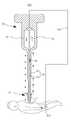
도 1 은 본 발명의 일 실시예에 따른 의료용 삽입 장치의 단면도이다.
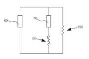
도 2 는 본 발명의 일 실시예에 따른 의료용 삽입 장치의 전류 발생기 및 인체가 형성하는 회로도이다.
도 3 은 본 발명에 따른 의료용 삽입 장치의 노출부의 확대도이다.
도 4 는 본 발명의 다른 실시예에 따른 의료용 삽입 장치의 단면도이다.
도 5 는 본 발명의 또 다른 실시예에 따른 의료용 삽입 장치의 단면도이다.
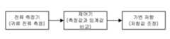
도 6 은 본 발명에 따른 의료용 삽입 장치의 가변 저항의 저항값이 조정되는 과정을 나타낸 개념도이다.1 is a cross-sectional view of a medical insertion device according to an embodiment of the present invention.
2 is a circuit diagram of a current generator and a human body of a medical inserting apparatus according to an embodiment of the present invention.
3 is an enlarged view of an exposed portion of the medical insertion device according to the present invention.
4 is a cross-sectional view of a medical insertion device according to another embodiment of the present invention.
5 is a cross-sectional view of a medical insertion device according to another embodiment of the present invention.
6 is a conceptual diagram illustrating a process of adjusting a resistance value of a variable resistor of the medical insertion apparatus according to the present invention.
본 발명의 이점 및 특징, 그리고 그것들을 달성하는 방법은 첨부되는 도면과 함께 상세하게 후술되어 있는 실시예들을 참조하면 명확해질 것이다. 그러나 본 발명은 이하에서 개시되는 실시예들에 한정되는 것이 아니라 서로 다른 다양한 형태로 구현될 것이며, 단지 본 실시예들은 본 발명의 개시가 완전하도록 하며, 본 발명이 속하는 기술분야에서 통상의 지식을 가진 자에게 발명의 범주를 완전하게 알려주기 위해 제공되는 것이며, 본 발명은 청구항의 범주에 의해 정의될 뿐이다. 명세서 전체에 걸쳐 동일 참조 부호는 동일 구성 요소를 지칭한다.BRIEF DESCRIPTION OF THE DRAWINGS The advantages and features of the present invention, and the manner of achieving them, will be apparent from and elucidated with reference to the embodiments described hereinafter in conjunction with the accompanying drawings. The present invention may, however, be embodied in many different forms and should not be construed as being limited to the embodiments set forth herein. Rather, these embodiments are provided so that this disclosure will be thorough and complete, and will fully convey the scope of the invention to those skilled in the art. Is provided to fully convey the scope of the invention to those skilled in the art, and the invention is only defined by the scope of the claims. Like reference numerals refer to like elements throughout the specification.
본 명세서에서 사용된 용어는 실시예들을 설명하기 위한 것이며 본 발명을 제한하고자 하는 것은 아니다. 본 명세서에서, 단수형은 문구에서 특별히 언급하지 않는 한 복수형도 포함한다. 명세서에서 사용되는 "포함한다(comprises)" 및/또는 "포함하는(comprising)"은 언급된 구성요소, 단계 및 동작은 하나 이상의 다른 구성요소, 단계 및 동작의 존재 또는 추가를 배제하지 않는다.The terminology used herein is for the purpose of illustrating embodiments and is not intended to be limiting of the present invention. In the present specification, the singular form includes plural forms unless otherwise specified in the specification. It is noted that the terms " comprises "and / or" comprising ", as used herein, do not exclude the presence or addition of one or more other elements, steps and operations.
도 1 내지 3 을 참조하여, 본 발명의 일 실시예에 따른 의료용 삽입 장치를 설명한다. 도 1 은 본 발명의 일 실시예에 따른 의료용 삽입 장치의 단면도이다. 도 2 는 본 발명의 일 실시예에 따른 의료용 삽입 장치의 전류 발생기 및 인체가 형성하는 회로도이다. 도 3 은 본 발명에 따른 의료용 삽입 장치의 노출부의 확대도이다.1 to 3, a medical insertion device according to an embodiment of the present invention will be described. 1 is a cross-sectional view of a medical insertion device according to an embodiment of the present invention. 2 is a circuit diagram of a current generator and a human body of a medical inserting apparatus according to an embodiment of the present invention. 3 is an enlarged view of an exposed portion of the medical insertion device according to the present invention.
도 1 내지 3 을 참조하면, 본 발명의 일 실시예에 따른 의료용 삽입 장치(100)는 나사못(10), 드라이버(20), 전류 발생기(60), 전류 측정기(70), 도체 부재(50) 및 가변 저항(80)을 포함한다. 한편, 본 발명의 이해를 돕고자 도면 상에서 의료용 삽입 장치를 인체에 비해서 확대하여 표현하였다.1 to 3, a
나사못(10)은 신경에 인접한 뼈의 조직(350)에 삽입되는 골유합 나사못(10), 특히 척추 등에 삽입되는 척추경 나사못(10)일 수 있다. 이렇게 나사못(10)은 인체 내부에 삽입되기 위해서 외측에 나사산이 형성될 수 있다. 또한, 나사못(10)은 인체에 삽입되기 때문에 생체 적합성과 강도가 우수하여 각종 임플란트용 재료로 사용되고 있는 티타늄 재질로 제작될 수 있다.The
나사못(10)의 전단부에는 태핑 나사(T)가 형성될 수 있으며, 태핑 나사(T)는 나사못(10)이 인체 내부에 삽입되기 전에 미리 천공 작업을 진행하고, 그에 따라 태핑 나사(T)에 의해 확보된 구멍을 통하여 나사못(10)을 보다 안전하게 삽입할 수 있다.A tapping screw T may be formed at the front end of the
드라이버(20)는 나사못(10)을 인체에 삽입시키거나 삽입된 나사못(10)을 인체로부터 제거하는 부재로서, 본 발명의 일 실시예에 따른 의료용 삽입 장치(100)의 경우 나사못(10)과 드라이버(20)는 일체형을 이루고, 드라이버(20)가 회전함에 따라 드라이버(20)와 일체를 이루는 나사못(10) 역시 시계 방향 또는 반시계방향으로 회전하면서 인체에 삽입되거나 인체로부터 제거될 수 있다.The
전류 발생기(60)는 드라이버(20) 내부에 위치할 수 있으며, 도체 부재를 통해 인체로 흘려보내는 전류를 발생시키는 부재이다.The
전류 측정기(70)는 드라이버(20) 내부에 위치할 수 있으며, 전류 발생기(60)에서 발생된 전류가 인체의 저항과 전류 분배되어 전류 측정기로 흐르는 전류량(즉, 전류 중에서 인체로 흐르지 않은 전류의 전류량)을 측정하는 부재이다. 전류 발생기(60)에서 전류를 인체로 인가하고 이후 일부의 전류가 인체로 흘러들어가고 나머지 전류가 전류 측정기(70)로 돌아가게 되는 바, 전류 측정기(60)로 돌아온 전류량을 측정하여 인체로 흐른 전류량을 파악할 수 있고, 그에 따라 전류가 흘러들어간 인체 내 조직(350)의 저항값을 산출할 수 있다. 이렇게 산출된 저항값과 이미 알고 있는 조직(350)의 종류에 따른 고유 저항값을 비교하여 전류가 흘러들어간 조직(350)이 신경인지 근육인지 파악할 수 있게 된다.The
한편, 인체로 흘러들어간 전류는 다리와 같이 인체의 특정 부위에 장착된 그라운드 부재(400)를 통해 외부로 나온 후에 그라운드 부재(400)와 연결된 복귀 부재(450)를 흐르면서 전류 발생기(60)로 복귀하고, 그에 따라 본 발명에 따른 의료용 삽입 장치(100)는 하나의 폐회로를 구성할 수 있다(도 2 참조). 또한, 복귀 부재(450)는 백금, 금, 은, 텅스텐 등으로 구성될 수 있으며, 인체에 대한 적합성이 검증되고, 전기 전도율이 매우 우수한 재질이라면 재질에 있어서 제한이 없다.On the other hand, the current flowing into the human body returns to the
도체 부재(50)는 나사못(10) 및 드라이버(20) 내부에서 길이 방향을 따라 위치하며 외부에 노출되는 노출부(S)를 포함하고, 이 노출부(S)를 통해 전류 발생기(60)에서 발생된 전류를 인체 내 조직(350)으로 흘려보냄으로써 삽입되는 나사못(10) 주위에 위치한 조직(350)의 종류를 파악할 수 있고, 그에 따라 나사못(10) 삽입 과정에서 나사못(10)이 신경과 접촉하지 않도록 할 수 있다.The
이를 위해, 도체 부재(50)는 전류 발생기(60)와 연결되어 전류 발생기(60)에서 발생된 전류를 인체로 흐르도록 하는 인가 도체 부재(30) 및 일단이 인가 도체 부재(30)와 전기적으로 연결되며 타단이 전류 발생기(60)와 연결되고(이렇게 됨으로써 하나의 폐회로를 구성함), 가변 저항 및 전류 측정기가 설치되어 전류 발생기에서 생성된 전류가 인체의 저항과 전류 분배되어 전류 측정기로 흐르도록 하는 귀류 도체 부재(40)를 포함할 수 있다.To this end, the
즉, 전류 발생기(60), 인가 도체 부재(30), 귀류 도체 부재(40) 및 전류 측정기(70)는 하나의 폐회로를 형성하고, 전류 발생기(60)에서 발생된 전류 중 일부 전류는 인가 도체 부재(30)를 흐르면서 인체 내 조직(350)으로 흘러들어가고 나머지 전류는 귀류 도체 부재(40)를 통해 전류 측정기(70)를 거쳐 전류 발생기(60)로 흐르게 된다. 따라서 감소된 전류량 또는 전류가 흘러들어간 조직(350)의 저항값을 파악하여 전류가 흘러들어간 조직(350)이 신경인지 아니면 근육인지를 파악할 수 있게 된다.That is, the
도 3 을 참고하여, 도체 부재(50)의 노출부(S)를 살펴보면, 노출부(S)는 인가 도체 부재(30)와 귀류 도체 부재(40)가 직접 연결되어 형성된 부분이며 나사못(10) 전단부의 외부 둘레에 위치할 수 있다. 즉, 노출부(S)는 인가 도체 부재(30)와 귀류 도체 부재(40)가 접한 부분 및 그 주위 부분으로 이루어질 수 있으며, 나사못(10) 전단부의 외부 둘레에 부착될 수 있다.3, the exposed portion S of the
다르게는, 노출부(S)는 나사못(10) 전단부의 외면을 형성하며 인가 도체 부재(30) 및 귀류 도체 부재(40)와 연결될 수 있다(도 3(a) 참조). 이 경우 노출부(S)는 인가 도체 부재(30) 및 귀류 도체 부재(40)와는 별개의 도체 몸체(35)일 수 있으며, 이 도체 몸체(35)는 나사못(10) 전단부에 부착되고 또한 인가 도체 부재(30) 및 귀류 도체 부재(40)와 연결될 수 있다. 이러한 도체 몸체(35)를 적용함으로써 도체 부재(50)가 신경과 접촉하는 면적을 증가시킬 수 있어 보다 용이하게 신경을 감지할 수 있다.Alternatively, the exposed portion S forms the outer surface of the front end of the
또 다르게는, 노출부(S)는 나사못(10) 전단부의 둘레를 감싸는 링 형상이며 인가 도체 부재(30) 및 귀류 도체 부재(40)와 연결될 수 있다(도 3(b) 참조). 이 링 형상의 도체 부재(45)는 나사못(10) 전단부로부터 일정 거리 이격된 위치에서 나사못(10)의 둘레를 감쌀 수 있고, 또한 링 형상의 도체 부재(45)는 두개 이상일 수 있다.Alternatively, the exposed portion S may be ring-shaped surrounding the periphery of the front end portion of the
한편, 도체 부재(50)는 백금, 금, 은, 텅스텐 등으로 구성될 수 있으며, 인체에 대한 적합성이 검증되고, 전기 전도율이 매우 우수하여 미세한 EMG(근전도) 신호를 검출하는 데에 적합한 재질이라면 재질에 있어서 제한이 없다.On the other hand, if the
가변 저항(80)은 전류가 흘러들어간 조직(350)의 종류를 정확하게 파악하기 위해서 사용될 수 있다. 이와 관련하여, 종래의 의료용 삽입 장치의 경우, 금 등으로 제조된 도체 부재(50)에 비하여 신경의 저항값이 높기 때문에 인가된 전류가 신경으로 흐르지 못하고 다시 되돌아 전류 측정기(70)로 이동하게 된다. 따라서, 전류가 흐른 조직(350)의 저항값을 파악할 수 없으며 그에 따라 조직(350)의 종류를 정확하게 파악하는데 어려움이 있어왔다.The
이러한 문제점을 해결하기 위해서, 본 발명의 경우는 가변 저항(80)을 설치하여 도체 부재(50)의 저항값을 높이고 그 결과 일정 전류가 조직(350)으로 흐르도록 하여 조직(350)의 종류를 정확하게 파악하도록 하고 있다. 아울러, 가변 저항(80)의 저항값은 자동으로 또는 수동으로 조정될 수 있으며, 가변 저항(80)을 자동으로 조정하기 위해 본 발명에 따른 의료용 삽입 장치는 제어기를 더 포함할 수 있다. 이러한 제어기는 다른 구성들과 일체로 형성될 수 있고 별개로서 형성될 수도 있으며, 그 설치 형태에는 제한이 없다.In order to solve this problem, in the present invention, the
구체적으로, 전류 측정기(70)가 설치된 귀류 도체 부재(40)에는 가변 저항(80)이 구비되어 가변 저항(80)의 저항값을 자동으로 또는 수동으로 조정하여 귀류 도체 부재(40)의 전체 저항값을 높이고, 그에 따라 전류 발생기(60)에서 발생된 전류가 신경을 포함한 인체 내 조직(350)으로 흐르도록 할 수 있다. 이후, 전류 측정기(70)로 돌아온 전류량(또는 조직(350)으로 흐른 전류량)과 가변 저항(80)의 저항값을 통해 전류가 흐른 조직(350)의 저항값을 산출하고, 산출된 저항값과 조직(350)의 고유 저항값을 비교하여 전류가 흐른 조직(350)의 종류를 용이하게 파악할 수 있다.The
한편, 도 6 을 통해 제어기가 가변 저항(80)의 저항값을 조정하는 과정을 살펴보면, 전류 측정기(70)는 귀류 전류량을 측정하고, 이 측정값을 제어기에 전달할 수 있다. 이후 제어기는 전달받은 귀류 전류량을 통해 인체로 흐른 전류량을 산출하고, 이 산출된 전류량과 미리 정해진 임계값을 비교하여 인체로 흐른 전류량이 임계값 미만으로 판단될 경우, 가변 저항의 저항값을 자동으로 조절하여 인체에 임계값 이상의 전류가 흐르도록 할 수 있다.Meanwhile, referring to FIG. 6, when the controller adjusts the resistance value of the
더욱이, 본 발명의 경우는, 전류가 흐른 인체의 조직(350)의 종류에 상관없이 전류 발생기(60)로부터 발생되는 전류량에 대한 전류 측정기(70)로 돌아오는 전류량의 비가 일정하도록 가변 저항(80)의 저항값을 자동으로 또는 수동으로 조정할 수 있다. 예를 들어, 돌아오는 전류량은 발생되는 전류량의 1/2이 되도록 가변 저항값을 조정할 수 있다. 이럴 경우, 전류가 흐르는 조직(350)이 신경일 때와 근육일 때 그 가변 저항(80)의 저항값이 차이가 나게 되며 이러한 저항값의 차이를 통해 조직(350)의 저항값을 산출할 수 있다. 이후 이미 알고 있는 조직(350)의 종류에 따른 고유 저항값과 산출된 조직(350)의 저항값을 비교하여 전류가 흐른 조직(350)이 신경인지 아니면 근육인지를 정확하게 파악할 수 있게 된다.Further, in the case of the present invention, the ratio of the amount of current returning to the
결과적으로, 가변 저항(80)을 도입함으로써 삽입되는 나사못(10) 주위 조직(350)의 종류를 정확하게 파악할 수 있는바, 나사못(10)이 인체 내에 삽입될 때 신경과의 접촉을 실시간으로 감지하여 신경의 손상을 방지할 수 있다.As a result, by introducing the
추가적으로, 드라이버(20)에는 표시창 또는 램프 및 표시창을 포함하는 디스플레이가 구비될 수 있다. 디스플레이를 통해서 전류의 감소를 시각적으로 확인할 수 있다. 구체적으로, 디스플레이에서 전류 발생기(60)에 의해 인가 도체 부재(30)로 인가된 전류와 전류 측정기(70)에 의해 측정된 전류를 숫자로 표시할 경우, 전류의 감소 여부를 쉽게 확인할 수 있다. 게다가, 전류 측정기(70)에 의해 측정된 전류가 전류 발생기(60)에 의해 인가 도체 부재(30)에 인가된 전류보다 작은 경우, 램프에서 불이 켜지게 하여 전류의 감소 여부를 쉽게 확인할 수 있다. 또는, 전류 측정기(70)에 의해 측정된 전류가 전류 발생기(60)에 의해 인가 도체 부재(30)에 인가된 전류보다 작은 경우, 알람이 울리게 하여 시각적으로뿐만 아니라 청각적으로 전류의 감소 여부를 쉽게 확인할 수 있다.In addition, the
이상 본 발명의 일 실시예에 따른 의료용 삽입 장치를 설명하였으며, 이하 도 4 를 참조하여 본 발명의 다른 실시예에 따른 의료용 삽입 장치를 설명한다. 도 4 는 본 발명의 다른 실시예에 따른 의료용 삽입 장치의 단면도이다.The medical insertion device according to an embodiment of the present invention has been described above, and the medical insertion device according to another embodiment of the present invention will be described with reference to FIG. 4 is a cross-sectional view of a medical insertion device according to another embodiment of the present invention.
도 4 를 참조하면, 본 발명의 다른 실시예에 따른 의료용 삽입 장치(200)는 나사못(110)과 드라이버(120)가 일체형이 아니며 별개의 구성이다. 별개의 구성인 나사못(110)과 드라이버(120)의 결합을 위해서, 나사못(110)의 헤드에는 암나사산이 형성된 결합홈이 존재하고, 드라이버(120)의 전단부에는 나사못(110)의 암나사산에 대응하는 수나사산이 형성되어 있어, 나사못(110)과 드라이버(120)는 맞물려 결합될 수 있다. 그러나, 나사못(110)과 드라이버(120)의 결합 방식은 전술한 방식에 한정되는 것은 아니며 다양한 결합 방식이 사용될 수 있다.Referring to FIG. 4, the
또한, 인가 도체 부재는 나사못(110) 내부에 위치한 제 1 도체 부재(130) 및 드라이버(120) 내부에 위치한 제 2 도체 부재(140)를 포함할 수 있고, 귀류 도체 부재는 나사못(110) 내부에 위치한 제 3 도체 부재(135) 및 드라이버(120) 내부에 위치한 제 4 도체 부재(145)를 포함할 수 있다. 따라서, 제 2 도체 부재(140)는 전류 발생기(160)와 연결되고 제 4 도체 부재(145)는 전류 측정기(170)와 연결될 수 있다. 한편, 나사못(110)과 드라이버(120)가 맞물릴 때에 제 1 도체 부재(130)와 제 2 도체 부재(140)는 연결되어 하나의 인가 도체 부재를 형성하고, 제 3 도체 부재(135)와 제 4 도체 부재(145)는 연결되어 하나의 귀류 도체 부재를 형성할 수 있다.The applied conductor member may also include a
가변 저항(180)은 전류 측정기(170)와 연결된 제 4 도체 부재(145) 상에 설치되어 전류가 흐르는 조직(350)이 신경인지 아니면 근육인지를 정확하게 파악할 수 있게 된다. 한편, 인체로 흘러들어간 전류는 다리와 같이 인체의 특정 부위에 장착된 그라운드 부재(400)를 통해 외부로 나온 후에 그라운드 부재(400)와 연결된 복귀 부재(450)를 흐르면서 전류 발생기(160)로 복귀하고, 그에 따라 본 발명에 따른 의료용 삽입 장치(200)는 하나의 폐회로를 구성할 수 있다.The
노출부(S)의 경우는 전술한 본 발명의 일 실시예에 따른 의료용 삽입 장치(100)와 마찬가지로, 제 1 도체 부재(130)와 제 3 도체 부재(135)가 직접 연결되어 노출부(S)를 형성하거나, 별개의 도체 몸체 및 링 형상의 도체가 사용되어 노출부를 형성할 수 있다.In the case of the exposed portion S, the
이상 본 발명의 다른 실시예에 따른 의료용 삽입 장치를 설명하였으며, 이하 도 5 를 참조하여 본 발명의 또 다른 실시예에 따른 의료용 삽입 장치를 설명한다. 도 5 는 본 발명의 또 다른 실시예에 따른 의료용 삽입 장치의 단면도이다.The medical insertion device according to another embodiment of the present invention has been described above, and a medical insertion device according to another embodiment of the present invention will be described with reference to FIG. 5 is a cross-sectional view of a medical insertion device according to another embodiment of the present invention.
도 5 를 참조하면, 본 발명의 또 다른 실시예에 따른 의료용 삽입 장치(300)는 드라이버(210) 내부에 전류 발생기, 전류 측정기 및 가변 저항이 설치되어 있지 않고, 대신에 드라이버(210) 외부에 별도로 구비되어 있다. 구체적으로, 본 발명의 또 다른 실시예에 따른 의료용 삽입 장치(300)는, 도체 부재로 흐르는 전류를 발생시키는 전류 발생기(250), 전류 발생기(250)에서 발생된 후 인체를 거쳐 돌아오는 전류량을 측정하는 전류 측정기(260) 및 전류 측정기(260)로 돌아오는 전류의 경로 상에 설치된 가변 저항(270)을 포함하는 외부 전류 발생 장치(280)를 포함한다. 이렇게, 전류 발생기(250) 및 전류 측정기(260)가 외부에 있음으로 인해서 전류 발생기(250) 및 전류 측정기(260)의 유지 보수가 용이하다는 장점이 있다.5, a
또한, 인가 도체 부재는 나사못(110) 내부에 위치한 제 1 도체 부재(220) 및 드라이버(210) 내부에서 외부로 연장되어 전류 발생기에 연결된 제 5 도체 부재(230)를 포함하고, 귀류 도체 부재는 나사못(110) 내부에 위치한 제 3 도체 부재(225) 및 드라이버(210) 내부에서 외부로 연장되어 전류 측정기(260)에 연결된 제 6 도체 부재(235)를 포함하고, 가변 저항(270)은 외부 전류 발생 장치(280) 내의 제 6 도체 부재(235) 상에 설치될 수 있다. 물론, 경우에 따라서 가변 저항(270)은 외부 전류 발생 장치(280) 내부가 아닌 제 6 도체 부재(235) 상에 설치될 수도 있다.The applied conductor member includes a
아울러, 나사못(110)과 드라이버(210)는 일체형이 아닌 별개의 구성일 수 있으며, 이러한 나사못(110)과 드라이버(210)가 맞물릴 때에 제 1 도체 부재(220)와 제 5 도체 부재(230)는 연결되어 하나의 인가 도체 부재를 형성하고, 제 3 도체 부재(225)와 제 6 도체 부재(235)는 연결되어 하나의 귀류 도체 부재를 형성할 수 있다.The
한편, 도 5 에는 나사못(110)과 드라이버(210)가 별개의 구성으로 도시되었으나, 도 1 과 같이 나사못(110)과 드라이버(210)가 일체형을 이루는 경우를 고려할 수 있고, 이러한 일체형 의료용 삽입 장치에 있어서 외부 전류 발생 장치(280)가 구비될 수도 있다.Although the
추가적으로, 노출부(S)의 경우는 전술한 의료용 삽입 장치와 마찬가지로, 제 1 도체 부재(220)와 제 3 도체 부재(225)가 직접 연결되어 노출부를 형성하거나, 별개의 도체 몸체 및 링 형상의 도체가 사용되어 노출부를 형성할 수 있다.In addition, in the case of the exposed portion S, the
한편, 인체로 흘러들어간 전류는 다리와 같이 인체의 특정 부위에 장착된 그라운드 부재(400)를 통해 외부로 나온 후에 그라운드 부재(400)와 연결된 복귀 부재(450)를 흐르면서 전류 발생기(250)로 복귀하고, 그에 따라 본 발명에 따른 의료용 삽입 장치(300)는 하나의 폐회로를 구성할 수 있다.On the other hand, the current flowing into the human body is returned to the
10, 100: 나사못20, 120, 210: 드라이버
30: 인가 도체 부재 40: 귀류 도체 부재
50, 150, 240: 도체 부재60, 160, 250: 전류 발생기
70, 170, 260: 전류 측정기80, 180, 270: 가변 저항
100, 200, 300: 의료용 삽입 장치130, 220: 제 1 도체 부재
135, 225: 제 3 도체 부재140: 제 2 도체 부재
145: 제 4 도체 부재230: 제 5 도체 부재
235: 제 6 도체 부재280: 외부 전류 발생 장치
400: 그라운드 부재450: 복귀 부재10, 100:
30: Applying conductor member 40:
50, 150, 240:
70, 170, 260: current measuring
100, 200, 300:
135, 225: third conductor member 140: second conductor member
145: fourth conductor member 230: fifth conductor member
235: sixth conductor member 280: external current generator
400: ground member 450: return member
Claims (26)
Translated fromKorean상기 나사못을 상기 인체에 삽입시키는 드라이버;
상기 드라이버 내부에 위치하며 소정의 전류를 발생시키는 전류 발생기;
상기 드라이버 내부에 위치하면 전류를 측정하는 전류 측정기; 및
상기 나사못 및 드라이버 내부에서 길이 방향을 따라 위치하며 외부에 노출되는 노출부를 포함하는 도체 부재를 포함하고,
상기 도체 부재는 상기 전류 발생기와 연결되어 상기 전류 발생기에서 발생된 전류를 상기 인체로 흐르도록 하는 인가 도체 부재 및 일단이 상기 인가 도체 부재와 전기적으로 연결되며 타단이 상기 전류 발생기와 연결되고, 가변 저항 및 상기 전류 측정기가 설치되어 상기 전류 발생기에서 생성된 전류가 상기 인체의 저항과 전류 분배되면서 상기 전류 측정기로 흐르도록 하는 귀류 도체 부재를 포함하는 의료용 삽입 장치.Screws inserted into the body;
A driver for inserting the screw into the human body;
A current generator located inside the driver and generating a predetermined current;
A current meter for measuring a current when the driver is located inside the driver; And
And a conductor member which is disposed along the longitudinal direction inside the screw and the driver and includes an exposed portion exposed to the outside,
Wherein the conductor member is connected to the current generator and has an applied conductor member for flowing a current generated from the current generator to the human body, one end electrically connected to the applied conductor member and the other end connected to the current generator, And a current conductor provided on the current measuring unit to cause a current generated by the current generator to flow to the current meter while being divided into current and resistance of the human body.
상기 전류 측정기에서 측정 결과 상기 인체로 흐른 전류량이 미리 정해진 임계값 미만으로 판단될 경우, 상기 가변 저항의 저항값을 수동 또는 자동으로 조절하여 상기 인체에 상기 임계값 이상의 전류가 흐르도록 하는 의료용 삽입 장치.The method according to claim 1,
Wherein the resistance value of the variable resistor is manually or automatically adjusted to allow a current equal to or greater than the threshold value to flow to the human body when the amount of current flowing into the human body is less than a predetermined threshold value .
상기 전류 측정기에서 측정한 전류량 및 상기 가변 저항의 저항값을 통해 전류가 흐른 인체 조직의 저항값을 산출하고, 산출된 저항값과 조직의 고유 저항값을 비교함으로써 상기 조직의 종류를 파악하는 의료용 삽입 장치.The method according to claim 1,
A medical inserter for calculating a resistance value of a human body through which a current flows through a current amount measured by the current meter and a resistance value of the variable resistor and comparing the calculated resistance value with a resistivity value of the tissue, Device.
상기 가변 저항을 조정하여 상기 전류 발생기로부터 발생되는 전류량에 대한 상기 전류 측정기로 돌아오는 전류량의 비를 일정하게 함으로써 전류가 흐른 인체 조직의 저항값을 산출하고, 산출된 저항값과 조직의 고유 저항값을 비교함으로써 상기 조직의 종류를 파악하는 의료용 삽입 장치.The method of claim 3,
The resistance value of the human tissue in which the current flows is calculated by adjusting the variable resistor so that the ratio of the amount of current returning to the current measuring device to the amount of current generated from the current generator is made constant and the resistance value of the tissue and the intrinsic resistance value To determine the type of the tissue.
상기 인체로 흐른 전류는 상기 인체에 장착된 그라운드 부재를 통해 외부로 나온 후에 복귀 부재를 통해 상기 전류 발생기로 흐르는 의료용 삽입 장치.The method according to claim 1,
Wherein the current flowing to the human body flows out to the outside through the ground member mounted on the human body, and then flows to the current generator through the return member.
상기 나사못과 드라이버는 일체형인 의료용 삽입 장치.The method according to claim 1,
Wherein the screw and the screwdriver are integral with each other.
상기 나사못의 전단부에는 태핑 나사가 형성된 의료용 삽입 장치.The method according to claim 6,
And a tapping screw is formed at a front end portion of the screw.
상기 나사못의 헤드에는 암나사산이 형성된 결합홈이 존재하고, 상기 드라이버의 전단부에는 상기 암나사산에 대응하는 수나사산이 형성되어 있어, 상기 나사못과 드라이버는 맞물릴 수 있는 의료용 삽입 장치.The method according to claim 1,
Wherein a screw groove is formed in the head of the screw and a screw thread corresponding to the female thread is formed at a front end of the screw driver so that the screw and the screw can be engaged with each other.
상기 인가 도체 부재는 상기 나사못 내부에 위치한 제 1 도체 부재 및 상기 드라이버 내부에 위치한 제 2 도체 부재를 포함하고,
상기 귀류 도체 부재는 상기 나사못 내부에 위치한 제 3 도체 부재 및 상기 드라이버 내부에 위치한 제 4 도체 부재를 포함하고,
상기 나사못과 드라이버가 맞물릴 때에 상기 제 1 도체 부재와 제 2 도체 부재는 연결되고 상기 제 3 도체 부재와 제 4 도체 부재는 연결되는 의료용 삽입 장치.9. The method of claim 8,
Wherein the applied conductor member includes a first conductor member located within the screw and a second conductor member located within the driver,
Wherein said return conductor member includes a third conductor member located within said screw and a fourth conductor member located within said driver,
Wherein the first conductor member and the second conductor member are connected and the third conductor member and the fourth conductor member are connected when the screw and the driver are engaged with each other.
상기 노출부는 상기 인가 도체 부재와 귀류 도체 부재가 직접 연결되어 형성된 부분이며 나사못 전단부의 외부 둘레에 위치하는 의료용 삽입 장치.The method according to claim 1,
Wherein the exposed portion is a portion formed by directly connecting the applied conductor member and the return conductive member, and is located at the outer periphery of the screw front end portion.
상기 노출부는 나사못 전단부의 외면을 형성하며 상기 인가 도체 부재 및 귀류 도체 부재와 연결된 의료용 삽입 장치.The method according to claim 1,
Wherein the exposed portion forms an outer surface of the screw front end portion and is connected to the applied conductive member and the conductive member.
상기 노출부는 나사못 전단부의 둘레를 감싸는 링 형상이며 상기 인가 도체 부재 및 귀류 도체 부재와 연결된 의료용 삽입 장치.The method according to claim 1,
Wherein the exposed portion is ring-shaped surrounding the periphery of the screw front end portion and is connected to the applied conductor member and the return conductor member.
상기 나사못을 상기 인체에 삽입시키는 드라이버;
상기 나사못 및 드라이버 외부에 위치하며 소정의 전류를 발생시키는 전류 발생기;
상기 나사못 및 드라이버 외부에 위치하면 전류를 측정하는 전류 측정기; 및
상기 전류 발생기에서 나와 상기 나사못 및 드라이버 내부를 거친 후에 상기 전류 발생기로 들어가고, 상기 인체와 접촉하는 노출부를 포함하는 도체 부재를 포함하고,
상기 도체 부재는 상기 전류 발생기와 연결되어 상기 전류 발생기에서 발생된 전류를 상기 인체로 흐르도록 하는 인가 도체 부재 및 일단이 상기 인가 도체 부재와 전기적으로 연결되며 타단이 상기 전류 발생기와 연결되고, 가변 저항 및 상기 전류 측정기가 설치되어 상기 전류 발생기에서 생성된 전류가 상기 인체의 저항과 전류 분배되면서 상기 전류 측정기로 흐르도록 하는 귀류 도체 부재를 포함하는 의료용 삽입 장치.Screws inserted into the body;
A driver for inserting the screw into the human body;
A current generator positioned outside the screw and the driver and generating a predetermined current;
A current meter for measuring a current when the screw and the driver are located outside; And
And a conductor member which enters the current generator after passing through the screw generator and the screwdriver and inside the driver and includes an exposed portion for contacting the human body,
Wherein the conductor member is connected to the current generator and has an applied conductor member for flowing a current generated from the current generator to the human body, one end electrically connected to the applied conductor member and the other end connected to the current generator, And a current conductor provided on the current measuring unit to cause a current generated by the current generator to flow to the current meter while being divided into current and resistance of the human body.
상기 전류 측정기에서 측정 결과 상기 인체로 흐른 전류량이 미리 정해진 임계값 미만으로 판단될 경우, 상기 가변 저항의 저항값을 수동 또는 자동으로 조절하여 상기 인체에 상기 임계값 이상의 전류가 흐르도록 하는 의료용 삽입 장치.14. The method of claim 13,
Wherein the resistance value of the variable resistor is manually or automatically adjusted to allow a current equal to or greater than the threshold value to flow to the human body when the amount of current flowing into the human body is less than a predetermined threshold value .
상기 전류 측정기에서 측정한 전류량 및 상기 가변 저항의 저항값을 통해 전류가 흐른 인체 조직의 저항값을 산출하고, 산출된 저항값과 조직의 고유 저항값을 비교함으로써 상기 조직의 종류를 파악하는 의료용 삽입 장치.14. The method of claim 13,
A medical inserter for calculating a resistance value of a human body through which a current flows through a current amount measured by the current meter and a resistance value of the variable resistor and comparing the calculated resistance value with a resistivity value of the tissue, Device.
상기 가변 저항을 조정하여 상기 전류 발생기로부터 발생되는 전류량에 대한 상기 전류 측정기로 돌아오는 전류량의 비를 일정하게 함으로써 전류가 흐른 인체 조직의 저항값을 산출하고, 산출된 저항값과 조직의 고유 저항값을 비교함으로써 상기 조직의 종류를 파악하는 의료용 삽입 장치.16. The method of claim 15,
The resistance value of the human tissue in which the current flows is calculated by adjusting the variable resistor so that the ratio of the amount of current returned to the current measuring device to the amount of current generated from the current generator is made constant, To determine the type of the tissue.
상기 인체로 흐른 전류는 상기 인체에 장착된 그라운드 부재를 통해 외부로 나온 후에 복귀 부재를 통해 상기 전류 발생기로 흐르는 의료용 삽입 장치.14. The method of claim 13,
Wherein the current flowing to the human body flows out to the outside through the ground member mounted on the human body, and then flows to the current generator through the return member.
상기 나사못과 드라이버는 일체형인 의료용 삽입 장치.14. The method of claim 13,
Wherein the screw and the screwdriver are integral with each other.
상기 나사못의 전단부에는 태핑 나사가 형성된 의료용 삽입 장치.19. The method of claim 18,
And a tapping screw is formed at a front end portion of the screw.
상기 나사못의 헤드에는 암나사산이 형성된 결합홈이 존재하고, 상기 드라이버의 전단부에는 상기 암나사산에 대응하는 수나사산이 형성되어 있어, 상기 나사못과 드라이버는 맞물릴 수 있는 의료용 삽입 장치.14. The method of claim 13,
Wherein a screw groove is formed in the head of the screw and a screw thread corresponding to the female thread is formed at a front end of the screw driver so that the screw and the screw can be engaged with each other.
상기 인가 도체 부재는 상기 나사못 내부에 위치한 제 1 도체 부재 및 상기 드라이버 내부에서 외부로 연장되어 상기 전류 발생기에 연결된 제 5 도체 부재를 포함하고,
상기 귀류 도체 부재는 상기 나사못 내부에 위치한 제 3 도체 부재 및 상기 드라이버 내부에서 외부로 연장되어 상기 전류 측정기에 연결된 제 6 도체 부재를 포함하고,
상기 나사못과 드라이버가 맞물릴 때에 상기 제 1 도체 부재와 제 5 도체 부재는 연결되고 상기 제 3 도체 부재와 제 6 도체 부재는 연결되는 의료용 삽입 장치.21. The method of claim 20,
Wherein the applied conductor member includes a first conductor member located within the screw and a fifth conductor member extending outwardly from the driver and connected to the current generator,
The current conducting member includes a third conductor member located inside the screw and a sixth conductor member extending outward from the inside of the driver and connected to the current meter,
Wherein the first conductor member and the fifth conductor member are connected and the third conductor member and the sixth conductor member are connected when the screw and the driver are engaged with each other.
상기 노출부는 상기 인가 도체 부재와 귀류 도체 부재가 직접 연결되어 형성된 부분이며 나사못 전단부의 외부 둘레에 위치하는 의료용 삽입 장치.14. The method of claim 13,
Wherein the exposed portion is a portion formed by directly connecting the applied conductor member and the return conductive member, and is located at the outer periphery of the screw front end portion.
상기 노출부는 나사못 전단부의 외면을 형성하며 상기 인가 도체 부재 및 귀류 도체 부재와 연결된 의료용 삽입 장치.14. The method of claim 13,
Wherein the exposed portion forms an outer surface of the screw front end portion and is connected to the applied conductive member and the conductive member.
상기 노출부는 나사못 전단부의 둘레를 감싸는 링 형상이며 상기 인가 도체 부재 및 귀류 도체 부재와 연결된 의료용 삽입 장치.14. The method of claim 13,
Wherein the exposed portion is ring-shaped surrounding the periphery of the screw front end portion and is connected to the applied conductor member and the return conductor member.
상기 전류 발생기 및 전류 측정기를 수용하는 외부 전류 발생 장치를 더 포함하는 의료용 삽입 장치.14. The method of claim 13,
Further comprising an external current generator for receiving the current generator and the current meter.
상기 외부 전류 발생 장치는 상기 가변 저항을 더 수용하는 의료용 삽입 장치.26. The method of claim 25,
Wherein the external current generator further accommodates the variable resistor.
Priority Applications (4)
| Application Number | Priority Date | Filing Date | Title |
|---|---|---|---|
| KR1020160169966AKR101855743B1 (en) | 2016-12-13 | 2016-12-13 | Medical inserting apparatus |
| PCT/KR2017/014050WO2018110882A1 (en) | 2016-12-13 | 2017-12-04 | Medical insertion device |
| US16/468,442US11109899B2 (en) | 2016-12-13 | 2017-12-04 | Medical inserting apparatus |
| EP17881065.1AEP3536272B1 (en) | 2016-12-13 | 2017-12-04 | Medical insertion device |
Applications Claiming Priority (1)
| Application Number | Priority Date | Filing Date | Title |
|---|---|---|---|
| KR1020160169966AKR101855743B1 (en) | 2016-12-13 | 2016-12-13 | Medical inserting apparatus |
Publications (1)
| Publication Number | Publication Date |
|---|---|
| KR101855743B1true KR101855743B1 (en) | 2018-05-09 |
Family
ID=62200741
Family Applications (1)
| Application Number | Title | Priority Date | Filing Date |
|---|---|---|---|
| KR1020160169966AActiveKR101855743B1 (en) | 2016-12-13 | 2016-12-13 | Medical inserting apparatus |
Country Status (4)
| Country | Link |
|---|---|
| US (1) | US11109899B2 (en) |
| EP (1) | EP3536272B1 (en) |
| KR (1) | KR101855743B1 (en) |
| WO (1) | WO2018110882A1 (en) |
Cited By (2)
| Publication number | Priority date | Publication date | Assignee | Title |
|---|---|---|---|---|
| KR20200001133A (en) | 2018-06-27 | 2020-01-06 | 경북대학교 산학협력단 | Medical inserting apparatus and neuromonitoring system including the same |
| KR102714115B1 (en) | 2023-07-20 | 2024-10-07 | 대신엔터프라이즈(주) | Apparatus for measuring insertion depth of medical instruments inserted into the body and method for measuring insertion depth of medical instruments inserted into the body using the same |
Citations (1)
| Publication number | Priority date | Publication date | Assignee | Title |
|---|---|---|---|---|
| US20050059972A1 (en) | 2003-09-16 | 2005-03-17 | Spineco, Inc., An Ohio Corporation | Bone anchor prosthesis and system |
Family Cites Families (11)
| Publication number | Priority date | Publication date | Assignee | Title |
|---|---|---|---|---|
| US20060004431A1 (en)* | 2004-07-01 | 2006-01-05 | Fuller Thomas A | Prophylactic bactericidal implant |
| CA2580101A1 (en) | 2004-09-14 | 2006-03-23 | Spineco, Inc. | Implant device |
| US7559929B2 (en)* | 2005-02-18 | 2009-07-14 | Warsaw Orthopedic, Inc. | Implants and methods for positioning same in surgical approaches to the spine |
| US7981144B2 (en)* | 2006-09-21 | 2011-07-19 | Integrity Intellect, Inc. | Implant equipped for nerve location and method of use |
| KR20070011220A (en) | 2006-12-29 | 2007-01-24 | 이명철 | Odor removal device for toilet |
| US8348983B2 (en)* | 2007-11-13 | 2013-01-08 | Warsaw Orthopedic, Inc. | Surgical bone screw construction |
| US9737233B2 (en)* | 2009-09-09 | 2017-08-22 | Ryan A. Londot | Medical device for use with neuromonitoring equipment |
| KR101318844B1 (en)* | 2010-11-27 | 2013-10-17 | 서울대학교산학협력단 | Implant for neurotization by lectrostimulation |
| US20120185001A1 (en)* | 2011-01-14 | 2012-07-19 | Warsaw Orthopedic, Inc. | Bone Anchors Compatible for Use with Neural Integrity Monitoring Systems and Procedures |
| KR101599603B1 (en) | 2013-08-26 | 2016-03-03 | 경북대학교 산학협력단 | Medical inserting apparatus |
| KR20170045286A (en)* | 2014-08-26 | 2017-04-26 | 아벤트, 인크. | Method and system for identification of source of chronic pain and treatment |
- 2016
- 2016-12-13KRKR1020160169966Apatent/KR101855743B1/enactiveActive
- 2017
- 2017-12-04EPEP17881065.1Apatent/EP3536272B1/enactiveActive
- 2017-12-04WOPCT/KR2017/014050patent/WO2018110882A1/ennot_activeCeased
- 2017-12-04USUS16/468,442patent/US11109899B2/enactiveActive
Patent Citations (1)
| Publication number | Priority date | Publication date | Assignee | Title |
|---|---|---|---|---|
| US20050059972A1 (en) | 2003-09-16 | 2005-03-17 | Spineco, Inc., An Ohio Corporation | Bone anchor prosthesis and system |
Cited By (3)
| Publication number | Priority date | Publication date | Assignee | Title |
|---|---|---|---|---|
| KR20200001133A (en) | 2018-06-27 | 2020-01-06 | 경북대학교 산학협력단 | Medical inserting apparatus and neuromonitoring system including the same |
| KR102144041B1 (en) | 2018-06-27 | 2020-08-12 | 경북대학교 산학협력단 | Medical inserting apparatus and neuromonitoring system including the same |
| KR102714115B1 (en) | 2023-07-20 | 2024-10-07 | 대신엔터프라이즈(주) | Apparatus for measuring insertion depth of medical instruments inserted into the body and method for measuring insertion depth of medical instruments inserted into the body using the same |
Also Published As
| Publication number | Publication date |
|---|---|
| WO2018110882A1 (en) | 2018-06-21 |
| EP3536272A1 (en) | 2019-09-11 |
| US11109899B2 (en) | 2021-09-07 |
| EP3536272A4 (en) | 2020-07-08 |
| US20200397485A1 (en) | 2020-12-24 |
| EP3536272B1 (en) | 2024-02-14 |
Similar Documents
| Publication | Publication Date | Title |
|---|---|---|
| KR101599603B1 (en) | Medical inserting apparatus | |
| CN101951848B (en) | Implant equipped for nerve location and method of use | |
| EP1675508B1 (en) | System for performing dynamic pedicle integrity assessments | |
| AU2008240341B2 (en) | System and methods for performing percutaneous pedicle integrity assessments | |
| US7981144B2 (en) | Implant equipped for nerve location and method of use | |
| US10470707B2 (en) | System and methods for performing percutaneous pedicle integrity assessments | |
| US10172658B2 (en) | Medical insertion apparatus | |
| US20110264151A1 (en) | Bone fixation device and method of validating its proper placement | |
| AU2002353954A1 (en) | System and methods for performing percutaneous pedicle integrity assessments | |
| KR20040083455A (en) | Device for monitoring penetration into anatomical members | |
| RU2708319C2 (en) | Medical system | |
| WO2006132946A2 (en) | Pedicle impedence measuring probe | |
| KR101855743B1 (en) | Medical inserting apparatus | |
| US9737233B2 (en) | Medical device for use with neuromonitoring equipment | |
| Davis et al. | Can triggered electromyography be used to evaluate pedicle screw placement in hydroxyapatite-coated screws: an electrical examination | |
| KR101981981B1 (en) | Medical screw | |
| Norton et al. | Considering pedicle screw resistance in electromyography of the spine | |
| KR20180120889A (en) | Medical inserting apparatus and manufacturing method thereof | |
| KR102144041B1 (en) | Medical inserting apparatus and neuromonitoring system including the same | |
| Davis et al. | Pedicle screw electrical resistance: hydroxyapatite coated versus non-coated | |
| BR112017021168B1 (en) | MEDICAL SYSTEM DESIGNED TO PENETRATE AN ANATOMICAL STRUCTURE OF A PATIENT |
Legal Events
| Date | Code | Title | Description |
|---|---|---|---|
| PA0109 | Patent application | Patent event code:PA01091R01D Comment text:Patent Application Patent event date:20161213 | |
| PA0201 | Request for examination | ||
| PE0902 | Notice of grounds for rejection | Comment text:Notification of reason for refusal Patent event date:20180201 Patent event code:PE09021S01D | |
| E701 | Decision to grant or registration of patent right | ||
| PE0701 | Decision of registration | Patent event code:PE07011S01D Comment text:Decision to Grant Registration Patent event date:20180427 | |
| GRNT | Written decision to grant | ||
| PR0701 | Registration of establishment | Comment text:Registration of Establishment Patent event date:20180502 Patent event code:PR07011E01D | |
| PR1002 | Payment of registration fee | Payment date:20180502 End annual number:3 Start annual number:1 | |
| PG1601 | Publication of registration | ||
| PR1001 | Payment of annual fee | Payment date:20220419 Start annual number:5 End annual number:5 | |
| PR1001 | Payment of annual fee | Payment date:20230425 Start annual number:6 End annual number:6 | |
| PR1001 | Payment of annual fee | Payment date:20250430 Start annual number:8 End annual number:8 |