KR101855306B1 - Vapor deposition apparatus and plasma source - Google Patents
Vapor deposition apparatus and plasma sourceDownload PDFInfo
- Publication number
- KR101855306B1 KR101855306B1KR1020120071262AKR20120071262AKR101855306B1KR 101855306 B1KR101855306 B1KR 101855306B1KR 1020120071262 AKR1020120071262 AKR 1020120071262AKR 20120071262 AKR20120071262 AKR 20120071262AKR 101855306 B1KR101855306 B1KR 101855306B1
- Authority
- KR
- South Korea
- Prior art keywords
- electrode
- deposition apparatus
- vapor deposition
- plasma
- dielectric tube
- Prior art date
- Legal status (The legal status is an assumption and is not a legal conclusion. Google has not performed a legal analysis and makes no representation as to the accuracy of the status listed.)
- Expired - Fee Related
Links
Images


Classifications
- H—ELECTRICITY
- H01—ELECTRIC ELEMENTS
- H01J—ELECTRIC DISCHARGE TUBES OR DISCHARGE LAMPS
- H01J37/00—Discharge tubes with provision for introducing objects or material to be exposed to the discharge, e.g. for the purpose of examination or processing thereof
- H01J37/32—Gas-filled discharge tubes
- H01J37/32431—Constructional details of the reactor
- H01J37/32532—Electrodes
- H01J37/32559—Protection means, e.g. coatings
- C—CHEMISTRY; METALLURGY
- C23—COATING METALLIC MATERIAL; COATING MATERIAL WITH METALLIC MATERIAL; CHEMICAL SURFACE TREATMENT; DIFFUSION TREATMENT OF METALLIC MATERIAL; COATING BY VACUUM EVAPORATION, BY SPUTTERING, BY ION IMPLANTATION OR BY CHEMICAL VAPOUR DEPOSITION, IN GENERAL; INHIBITING CORROSION OF METALLIC MATERIAL OR INCRUSTATION IN GENERAL
- C23C—COATING METALLIC MATERIAL; COATING MATERIAL WITH METALLIC MATERIAL; SURFACE TREATMENT OF METALLIC MATERIAL BY DIFFUSION INTO THE SURFACE, BY CHEMICAL CONVERSION OR SUBSTITUTION; COATING BY VACUUM EVAPORATION, BY SPUTTERING, BY ION IMPLANTATION OR BY CHEMICAL VAPOUR DEPOSITION, IN GENERAL
- C23C16/00—Chemical coating by decomposition of gaseous compounds, without leaving reaction products of surface material in the coating, i.e. chemical vapour deposition [CVD] processes
- C23C16/04—Coating on selected surface areas, e.g. using masks
- C23C16/042—Coating on selected surface areas, e.g. using masks using masks
- H—ELECTRICITY
- H01—ELECTRIC ELEMENTS
- H01J—ELECTRIC DISCHARGE TUBES OR DISCHARGE LAMPS
- H01J37/00—Discharge tubes with provision for introducing objects or material to be exposed to the discharge, e.g. for the purpose of examination or processing thereof
- H01J37/32—Gas-filled discharge tubes
- H01J37/32431—Constructional details of the reactor
- H01J37/3244—Gas supply means
- H—ELECTRICITY
- H01—ELECTRIC ELEMENTS
- H01J—ELECTRIC DISCHARGE TUBES OR DISCHARGE LAMPS
- H01J37/00—Discharge tubes with provision for introducing objects or material to be exposed to the discharge, e.g. for the purpose of examination or processing thereof
- H01J37/32—Gas-filled discharge tubes
- H01J37/32431—Constructional details of the reactor
- H01J37/32532—Electrodes
- H01J37/32541—Shape
- H—ELECTRICITY
- H01—ELECTRIC ELEMENTS
- H01J—ELECTRIC DISCHARGE TUBES OR DISCHARGE LAMPS
- H01J37/00—Discharge tubes with provision for introducing objects or material to be exposed to the discharge, e.g. for the purpose of examination or processing thereof
- H01J37/32—Gas-filled discharge tubes
- H01J37/32431—Constructional details of the reactor
- H01J37/3266—Magnetic control means
- H01J37/32669—Particular magnets or magnet arrangements for controlling the discharge
Landscapes
- Chemical & Material Sciences (AREA)
- Engineering & Computer Science (AREA)
- Physics & Mathematics (AREA)
- Plasma & Fusion (AREA)
- Analytical Chemistry (AREA)
- General Chemical & Material Sciences (AREA)
- Chemical Kinetics & Catalysis (AREA)
- Materials Engineering (AREA)
- Mechanical Engineering (AREA)
- Metallurgy (AREA)
- Organic Chemistry (AREA)
- Chemical Vapour Deposition (AREA)
Abstract
Translated fromKoreanDescription
Translated fromKorean본 발명은 기상 증착장치 및 플라즈마 소스에 관한 것으로서, 더 상세하게는 플라즈마로부터 전극을 보호할 수 있는 기상 증착장치 및 플라즈마 소스에 관한 것이다.The present invention relates to a vapor deposition apparatus and a plasma source, and more particularly, to a vapor deposition apparatus and a plasma source capable of protecting an electrode from a plasma.
전자 소자의 제조에서, 화학적 기상 증착이나 원자층 증착과 같은 공정을 수행하는 기상 증착장치는 증착물질이 증착될 기판 등을 위치시킨 후 소스가스와 반응가스 등을 제공하여 물질층을 기판 상에 형성시킨다. 특히 플라즈마 에너지를 이용하여 물질층을 형성하는 경우, 증착 온도가 낮아져서, 예를 들어, 디스플레이 소자, 태양광 소자, 유기발광 소자 등과 같은, 전자 소자의 다른 구성요소들에 열적 손상을 완화할 수 있는 유리한 효과를 기대할 수 있다.BACKGROUND ART In the production of electronic devices, a vapor deposition apparatus that performs processes such as chemical vapor deposition and atomic layer deposition is a technique in which a substrate on which a deposition material is to be deposited is placed, and then a source gas and a reactive gas are provided, . Particularly, in the case of forming a material layer by using plasma energy, the deposition temperature is lowered, so that thermal damage to other components of the electronic device, such as a display device, a photovoltaic device, an organic light emitting device, An advantageous effect can be expected.
하지만, 통상적으로 플라즈마는 두 개의 전극 사이에서 발생하는데, 플라즈마에 의하여 전극의 온도가 상승하게 되며 이러한 고온의 전극은 공정가스와 반응하여 산화되는 현상이 발생할 수 있다. 본 발명은 상기와 같은 문제점을 포함하여 여러 문제점들을 해결하기 위한 것으로서, 플라즈마가 발생되는 영역과 전극을 분리하는 기상 증착장치 및 플라즈마 소스를 제공하는 것을 목적으로 한다. 그러나 이러한 과제는 예시적인 것으로, 이에 의해 본 발명의 범위가 한정되는 것은 아니다.Generally, however, a plasma is generated between two electrodes, the temperature of the electrode is raised by the plasma, and such a high temperature electrode may be oxidized by reacting with the process gas. It is an object of the present invention to provide a vapor deposition apparatus and a plasma source for separating electrodes from a region where a plasma is generated. However, these problems are exemplary and do not limit the scope of the present invention.
본 발명의 일 관점에 의한 기상 증착장치에 따르면, 내부에 중공이 형성된 제 1 전극, 상기 중공 내에 상기 제 1 전극과 이격되어 배치되는 제 2 전극을 포함한다. 나아가, 상기 제 2 전극을 둘러싸며 상기 제 1 전극과 이격되는 유전체 튜브를 포함한다. 상기 제 1 전극과 상기 유전체 튜브 사이에 플라즈마가 발생할 수 있다.According to an aspect of the present invention, there is provided a vapor deposition apparatus including a first electrode having a hollow therein, and a second electrode disposed in the hollow so as to be spaced apart from the first electrode. And a dielectric tube surrounding the second electrode and spaced apart from the first electrode. Plasma may be generated between the first electrode and the dielectric tube.
상기 기상 증착장치에 있어서, 상기 유전체 튜브는 상기 제 2 전극이 상기 유전체 장벽 방전에 의한 플라즈마에 노출되지 않도록 상기 제 2 전극을 둘러쌀 수 있다.In the vapor deposition apparatus, the dielectric tube may surround the second electrode so that the second electrode is not exposed to the plasma caused by the dielectric barrier discharge.
상기 기상 증착장치에 있어서, 상기 제 2 전극은 기둥 형상으로 신장되며, 상기 유전체 튜브 내에 삽입될 수 있다.In the vapor deposition apparatus, the second electrode extends in a columnar shape and can be inserted into the dielectric tube.
상기 기상 증착장치에 있어서, 상기 유전체 튜브는 세라믹을 포함하여 구성될 수 있으며, 예를 들어, 쿼츠 또는 알루미나를 포함하여 구성될 수 있다.In the vapor deposition apparatus, the dielectric tube may include ceramic, for example, quartz or alumina.
상기 기상 증착장치에 있어서, 상기 플라즈마는 유전체 장벽 방전에 의한 용량 결합형(capacitively coupled) 플라즈마일 수 있다.In the vapor deposition apparatus, the plasma may be a capacitively coupled plasma by dielectric barrier discharge.
상기 기상 증착장치에 있어서, 상기 유전체 튜브와 대향하는 상기 제 1 전극의 내측면 상에 배치된 유전체층을 더 포함할 수 있다.The vapor deposition apparatus may further include a dielectric layer disposed on an inner surface of the first electrode facing the dielectric tube.
상기 기상 증착장치에 있어서, 상기 제 1 전극의 하부면에 배치된 자력 쉴드부를 더 포함할 수 있다.The vapor deposition apparatus may further include a magnetic shield portion disposed on a lower surface of the first electrode.
상기 기상 증착장치에 있어서, 가스를 상기 제 1 전극과 상기 유전체 튜브 사이에 공급하도록 상기 중공에 연결된 제 1 유로 및 상기 제 1 유로를 통하여 공급된 상기 가스가 상기 플라즈마와 반응한 여기체를 피증착 구조체 상에 제공하도록 상기 중공에 연결된 제 2 유로를 더 포함할 수 있다.A first flow path connected to the hollow to supply a gas between the first electrode and the dielectric tube and a second flow path connected to the hollow through the first flow path, And a second flow path connected to the hollow for providing on the structure.
상기 기상 증착장치에 있어서, 상기 제 2 유로와 연결되는 상기 제 1 전극의 하부면에 배치되고, 강자성체로 이루어진, 자력 쉴드부를 더 포함할 수 있다.The vapor deposition apparatus may further include a magnetic force shield portion disposed on a lower surface of the first electrode connected to the second flow path and made of a ferromagnetic material.
상기 기상 증착장치에 있어서, 상기 제 2 전극은 제 1 방향으로 신장하는 기둥 형상을 가질 수 있으며, 상기 제 1 방향은, 상기 제 1 유로를 통하여 상기 반응가스가 공급되고 상기 제 2 유로를 통하여 상기 여기체가 제공되는 방향과 교차할 수 있다.In the vapor deposition apparatus, the second electrode may have a column shape extending in a first direction, and the first direction is a direction in which the reaction gas is supplied through the first flow path, It can intersect with the direction in which the excitation body is provided.
상기 기상 증착장치에 있어서, 상기 유전체 튜브와 대향하는 상기 제 1 전극의 내측면 상에 배치되고, 나아가, 상기 제 1 유로 및 상기 제 2 유로의 내측면 상으로 신장하는, 유전체층을 더 포함할 수 있다.The vapor deposition apparatus may further include a dielectric layer disposed on an inner surface of the first electrode facing the dielectric tube and further extending on the inner surfaces of the first flow path and the second flow path have.
본 발명의 다른 관점에 의한 기상 증착장치에 따르면, 소스가스를 하방으로 제공할 수 있는 소스가스 제공부, 반응가스를 하방으로 제공할 수 있는 반응가스 제공부, 상기 소스가스 제공부와 상기 반응가스 제공부 사이에 위치하며 가스를 펌핑할 수 있는 펌핑부 및 상기 소스가스 제공부, 상기 펌핑부, 및 상기 반응가스 제공부의 하방에서 피증착 구조체를 순차적으로 이송할 수 있는 이송부를 포함한다. 나아가, 상기 반응가스 제공부는, 내부에 중공이 형성된 제 1 전극, 상기 중공 내에 상기 제 1 전극과 이격되어 배치되는 제 2 전극 및 상기 제 2 전극을 둘러싸며 상기 제 1 전극과 이격되는 유전체 튜브를 포함한다. 상기 제 1 전극과 상기 유전체 튜브 사이에 플라즈마가 발생할 수 있다.According to another aspect of the present invention, there is provided a vapor deposition apparatus including: a source gas supply unit capable of supplying a source gas downward; a reaction gas supply unit capable of supplying a reaction gas downward; And a transfer unit capable of sequentially transferring the deposition structure under the source gas supply unit, the pumping unit, and the reaction gas supply unit. Further, the reaction gas supply unit may include a first electrode having a hollow therein, a second electrode disposed in the hollow so as to be spaced apart from the first electrode, and a dielectric tube surrounding the second electrode and spaced apart from the first electrode, . Plasma may be generated between the first electrode and the dielectric tube.
상기 기상 증착장치에 있어서, 상기 피증착 구조체는 기판 및 상기 기판 상의 금속 마스크를 포함할 수 있고, 상기 금속 마스크를 상기 기판 상에 고정하기 위하여 상기 기판의 하방에 배치한 자석에 의한 자력으로부터, 상기 플라즈마에 대한 영향을 감소시키기 위하여, 상기 피증착 구조체와 대향하는 상기 제 1 전극의 하부면에 배치된, 강자성체로 이루어진, 자력 쉴드부를 더 포함할 수 있다.In the vapor deposition apparatus, the deposited structure may include a substrate and a metal mask on the substrate, and the magnetic force generated by the magnet disposed below the substrate to fix the metal mask on the substrate And a magnetic shield portion made of a ferromagnetic material disposed on a lower surface of the first electrode facing the evaporated film structure to reduce the influence on the plasma.
상기 기상 증착장치에 있어서, 상기 펌핑부는 상기 반응가스 제공부보다 상기 소스가스 제공부에 더 인접한 제 1 펌핑부 및 상기 소스가스 제공부보다 상기 반응가스 제공부에 더 인접한 제 2 펌핑부를 포함할 수 있다. 나아가, 상기 제 1 펌핑부 및 상기 제 2 펌핑부 사이에 배치되고, 가스를 상기 피증착 구조체 상에 퍼지할 수 있는 퍼지부를 포함할 수 있다.In the vapor deposition apparatus, the pumping section may include a first pumping section that is closer to the source gas supply section than the reactive gas supply section and a second pumping section that is closer to the reactive gas supply section than the source gas supply section have. Further, a purge portion disposed between the first pumping portion and the second pumping portion and capable of purging gas on the evaporated structure may be included.
상기 기상 증착장치에 있어서, 상기 제 2 전극은 기둥 형상으로 신장되며, 상기 유전체 튜브 내에 삽입될 수 있다.In the vapor deposition apparatus, the second electrode extends in a columnar shape and can be inserted into the dielectric tube.
본 발명의 또 다른 관점에 의한 플라즈마 소스에 따르면, 내부에 중공이 형성된 제 1 전극, 상기 중공 내에 상기 제 1 전극과 이격되어 배치되는 제 2 전극 및 상기 제 2 전극을 둘러싸며 상기 제 1 전극과 이격되는, 유전체 튜브를 포함한다. 상기 제 1 전극과 상기 유전체 튜브 사이에 플라즈마가 발생할 수 있다. 나아가, 가스를 상기 제 1 전극과 상기 유전체 튜브 사이에 공급하도록 상기 중공에 연결된 제 1 유로 및 상기 제 1 유로를 통하여 공급된 상기 가스가 상기 플라즈마와 반응한 여기체를 피처리 구조체 상에 제공하도록 상기 중공에 연결된 제 2 유로를 포함한다.According to another aspect of the present invention, there is provided a plasma source comprising: a first electrode having a hollow therein; a second electrode disposed in the hollow space apart from the first electrode; Spaced, dielectric tube. Plasma may be generated between the first electrode and the dielectric tube. Further, a first flow path connected to the hollow to supply a gas between the first electrode and the dielectric tube and a gas supplied through the first flow path are provided on the structure to be treated, And a second flow path connected to the hollow.
상기 플라즈마 소스에 있어서, 상기 제 2 유로와 연결되는 상기 제 1 전극의 하부면에 배치된 자력 쉴드부를 더 포함할 수 있다.The plasma source may further include a magnetic shield portion disposed on a lower surface of the first electrode connected to the second flow path.
상기 플라즈마 소스에 있어서, 상기 제 2 전극은 기둥 형상으로 신장되며, 상기 유전체 튜브 내에 삽입될 수 있다In the plasma source, the second electrode may extend in a columnar form and may be inserted into the dielectric tube
상기한 바와 같이 이루어진 본 발명의 일 실시예에 따른 기상 증착장치 및 플라즈마 소스에 의하면, 플라즈마에 의하여 전극의 온도가 상승하는 것을 완화하고 전극이 산화하는 현상을 방지하여, 금속 파티클의 발생을 억제하고 공정의 불량을 방지할 수 있다. 물론 이러한 효과에 의해 본 발명의 범위가 한정되는 것은 아니다.According to the vapor deposition apparatus and the plasma source according to the embodiment of the present invention as described above, the rise of the temperature of the electrode due to the plasma is mitigated, the oxidation of the electrode is prevented, It is possible to prevent the defective process. Of course, the scope of the present invention is not limited by these effects.
도 1은 본 발명의 일 실시예에 따른 기상 증착장치의 일부를 보여주는 개략적인 단면도이다.
도 2는 본 발명의 일 실시예에 따른 기상 증착장치의 일부를 보여주는 개략적인 사시도이다.
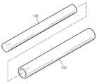
도 3은 본 발명의 일 실시예에 따른 기상 증착장치에서 제 2 전극이 유전체 튜브 내에 삽입되는 구성을 도해하는 분해 사시도이다.
도 4는 본 발명의 다른 실시예에 따른 기상 증착장치의 일부를 보여주는 개략적인 단면도이다.
도 5는 본 발명의 또 다른 실시예에 따른 기상 증착장치의 일부를 보여주는 개략적인 단면도이다.
도 6은 본 발명의 또 다른 실시예에 따른 기상 증착장치의 일부를 보여주는 개략적인 단면도이다.1 is a schematic cross-sectional view showing a part of a vapor deposition apparatus according to an embodiment of the present invention.
2 is a schematic perspective view showing a part of a vapor deposition apparatus according to an embodiment of the present invention.
3 is an exploded perspective view illustrating a configuration in which a second electrode is inserted into a dielectric tube in a vapor deposition apparatus according to an embodiment of the present invention.
4 is a schematic cross-sectional view showing a part of a vapor deposition apparatus according to another embodiment of the present invention.
5 is a schematic cross-sectional view showing a part of a vapor deposition apparatus according to another embodiment of the present invention.
6 is a schematic cross-sectional view showing a part of a vapor deposition apparatus according to another embodiment of the present invention.
이하, 첨부된 도면들을 참조하여 본 발명의 실시예를 상세히 설명하면 다음과 같다. 그러나 본 발명은 이하에서 개시되는 실시예에 한정되는 것이 아니라 서로 다른 다양한 형태로 구현될 수 있는 것으로, 이하의 실시예는 본 발명의 개시가 완전하도록 하며, 통상의 지식을 가진 자에게 발명의 범주를 완전하게 알려주기 위해 제공되는 것이다. 또한 설명의 편의를 위하여 도면에서는 구성 요소들이 그 크기가 과장 또는 축소될 수 있다.Hereinafter, embodiments of the present invention will be described in detail with reference to the accompanying drawings. It should be understood, however, that the invention is not limited to the disclosed embodiments, but may be embodied in many different forms and should not be construed as limited to the embodiments set forth herein. Rather, these embodiments are provided so that this disclosure will be thorough and complete, Is provided to fully inform the user. Also, for convenience of explanation, the components may be exaggerated or reduced in size.
이하의 실시예에서, X축, Y축 및 Z축은 직교 좌표계 상의 세 축으로 한정되지 않고, 이를 포함하는 넓은 의미로 해석될 수 있다. 예를 들어, X축, Y축 및 Z축은 서로 직교할 수도 있지만, 서로 직교하지 않는 서로 다른 방향을 지칭할 수도 있다.In the following embodiments, the X-axis, the Y-axis, and the Z-axis are not limited to three axes on the orthogonal coordinate system, and can be interpreted in a broad sense including the three axes. For example, the X-axis, Y-axis, and Z-axis may be orthogonal to each other, but may refer to different directions that are not orthogonal to each other.
본 발명에서 언급하는 기상 증착장치는 기상 상태의 증착기체의 반응에 의해서 물질층이 형성되는 화학적 기상 증착(chemical vapor deposition; CVD) 공정을 수행하는 장치를 포함할 수 있다. 나아가, 본 발명에서 언급하는 기상 증착장치는 기상 상태의 증착기체를 기판 상에 시분할 방식 또는 공간분할 방식으로 제공하는 단계를 반복하여, 원자층 증착(atomic layer deposition; ALD) 공정을 수행하는 장치를 포함할 수도 있다.The vapor deposition apparatus referred to in the present invention may include an apparatus for performing a chemical vapor deposition (CVD) process in which a material layer is formed by the reaction of a vapor deposition gas in a gaseous state. Furthermore, the vapor deposition apparatus referred to in the present invention is an apparatus for performing an atomic layer deposition (ALD) process by repeating the step of providing a vapor-phase deposition gas on a substrate in a time division manner or a space division manner .
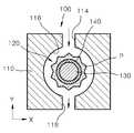
도 1은 본 발명의 일 실시예에 따른 기상 증착장치(100)의 일부를 보여주는 개략적인 단면도이고, 도 2는 본 발명의 일 실시예에 따른 기상 증착장치(100)의 일부를 보여주는 개략적인 사시도이다.FIG. 1 is a schematic cross-sectional view showing a part of a
도 1 및 도 2를 참조하면, 본 발명의 일 실시예에 따른 기상 증착장치(100)는 제 1 전극(110) 및 제 2 전극(130)을 포함한다. 제 1 전극(110)은 내부에 중공(120)이 형성될 수 있는데, 중공(120)은 제 1 전극(110)의 내측면(116)에 의하여 정의되는 공간을 포함하며, 예를 들어, Z 방향으로 신장할 수 있다. 제 2 전극(130)은 중공(120) 내에 제 1 전극(110)과 이격되어 배치될 수 있다. 제 2 전극(130)은 기둥 형상을 가지며 제 1 방향으로 신장될 수 있는데, 예를 들어, 원기둥, 타원기둥 또는 다각형 기둥 형상을 가지면서 Z 방향으로 신장할 수 있다. 여기에서, 기둥 형상은 속이 비어 있는 통 형상이 아니라 속이 채워진 기둥 형상을 포함할 수 있다. 제 1 전극(110) 및/또는 제 2 전극(130)은, 예를 들어, 알루미늄, 스테인레스와 같은, 금속 물질을 포함하여 구성될 수 있다. 예를 들어, 제 1 전극(110)은 알루미늄 계열의 금속을 포함하여 구성될 수 있으며, 제 2 전극(130)은 SUS(Steel Use Stainless) 계열의 금속을 포함하여 구성될 수 있다. 그러나, 본 발명이 기술적 사상은 제 1 전극(110) 및 제 2 전극(130)을 구성하는 물질의 종류에 의하여 한정되지 않음은 명백하다.Referring to FIGS. 1 and 2, a
유전체 튜브(140)가 제 2 전극(130)을 둘러싸면서 제 1 전극(110)과 이격되어 배치된다. 유전체 튜브(140)는 부도체로 구성되며, 예를 들어, 세라믹을 포함하여 구성될 수 있다. 예를 들면, 유전체 튜브(140)는 쿼츠(quartz) 또는 알루미나(alumina)를 포함하여 구성될 수 있다. 특히, 알루미나를 포함하여 구성된 유전체 튜브(140)는 쿼츠를 포함하여 구성된 유전체 튜브(140)보다 공정가스에 의한 표면 손상이 적어 바람직할 수 있다. 또한, 산화알루미늄(Al2O3)를 증착할 경우, 플라즈마 반응시 발생하는 파우더(powder) 등의 입자가 유전체 튜브(140)에 달라붙는 정도가 재질이 쿼츠인 경우보다 알루미나인 경우에서 완화되므로, 알루미나를 포함하여 구성된 유전체 튜브(140)가 산화알루미늄(Al2O3)증착공정에 유리하다.The
유전체 튜브(140)와 제 1 전극(110)의 내측면(116) 사이에는 유전체 장벽 방전(DBD: Dielectric Barrier Discharge)에 의한 플라즈마(P)가 발생될 수 있다. 유전체 장벽 방전에 의한 플라즈마는 저온 플라즈마로서 대기압 하에서도 발생이 가능한 플라즈마이다. 이를 위하여 제 1 전극(110) 및/또는 제 2 전극(130)에는 전압을 인가할 수 있는 전원부(미도시)가 연결될 수 있다. 상기 전원부는, 예를 들어, 교류형 또는 펄스형 전압을 인가할 수 있다. 플라즈마(P)는, 예를 들어, 용량 결합형(capacitively coupled) 플라즈마일 수 있다. 다만, 본 발명의 기술적 사상은 플라즈마(P)의 종류나 형태에 의하여 한정되지 않는다.A plasma P due to a dielectric barrier discharge (DBD) may be generated between the
유전체 튜브(140)를 도입하지 않은 상태에서 제 1 전극(110)과 제 2 전극(130) 사이에 플라즈마를 생성하는 경우, 제 2 전극(130)은 플라즈마에 의하여 노출되며, 플라즈마에 의하여 제 2 전극(130)의 표면은 고온 산화가 발생하여 금속 파티클이 발생할 수 있다. 이러한 문제점을 방지하기 위하여, 제 2 전극(130)을 둘러싸는 유전체 튜브(140)를 도입하였다. 유전체 튜브(140)에 의하여 플라즈마(P)가 생성되는 공간과 제 2 전극(130)을 분리할 수 있으며, 이로 인하여 제 2 전극(130)의 고온 산화를 원천적으로 방지할 수 있다. 제 2 전극(130)을 둘러싸는 유전체 튜브(140)의 구성은 유전체 튜브(140) 내에 제 2 전극(130)을 삽입함으로써 구현할 수 있다(도 3 참조). 따라서 유전체 튜브(140)의 내경은 제 2 전극(130)의 외경보다 클 수 있다.When the plasma is generated between the
발명자는 플라즈마로부터 제 2 전극(130)을 보호하기 위하여, 제 2 전극(130)의 표면 상에 용사코팅 또는 표면 산화처리를 수행하여 보호 세라믹층을 형성해 보았으나, 공정시간이 증가함에 따라 제 2 전극(130)가 고온 산화됨을 확인하였다. 이에 반하여, 유전체 튜브(140) 내에 제 2 전극(130)을 삽입함으로써 구현한 제 2 전극(130)을 둘러싸는 유전체 튜브(140)의 구성에 의할 경우, 플라즈마(P)가 발생되는 영역과 제 2 전극(130)이 분리되어 플라즈마(P)에 의해 제 2 전극(130)의 온도가 상승하는 것을 방지하고, 제 2 전극(130)이 공정가스에 직접적으로 노출되는 것을 방지하여 제 2 전극(130)이 고온 분위기에서 산화되는 것을 원천적으로 방지하며, 제 2 전극(130)의 산화가 억제되어 금속 파티클의 발생을 방지할 수 있음을 확인하였다.The inventor has tried to form a protective ceramic layer by spray coating or surface oxidation treatment on the surface of the
본 발명의 일 실시예에 따른 기상 증착장치(100)는 중공(120)에 각각 연결된 제 1 유로(114)와 제 2 유로(118)를 포함할 수 있다. 제 1 유로(114)는 제 1 전극(110)과 유전체 튜브(140) 사이에 소정의 가스, 예를 들어, 반응가스를 공급하도록 중공(120)에 연결될 수 있다. 제 2 유로(118)는 제 1 유로(114)를 통하여 공급된 상기 소정의 가스가 유전체 장벽 방전에 의한 플라즈마(P)와 반응한 여기체를 피증착 구조체 상에 제공하도록 중공(120)에 연결될 수 있다. 피증착 구조체는, 예를 들어,증착공정이 수행되는 기판을 포함할 수 있다. 한편, 상기 여기체는 상기 소정의 가스가 플라즈마(P)와 반응하여 여기된(excited) 물질을 포함하며, 예를 들어, 활성화된 이온, 전자, 라디칼 등을 포함할 수 있다.The
제 1 유로(114)와 제 2 유로(118)는 제 2 전극(130)을 중심으로 다른 방향으로 배치될 수 있다. 제 1 유로(114)는 상기 소정의 가스가 외부에서 공급되는 통로인 채널(112)에 연결될 수 있다. 제 1 유로(114)를 통하여 상기 소정의 가스가 공급되고 제 2 유로(118)를 통하여 여기체가 제공되는 방향(-Y 방향)은 제 2 전극(130)이 기둥 형상을 가지며 신장하는 방향(Z 방향)과 평행하지 않고 교차할 수 있으며, 예를 들어, 수직하게 교차할 수 있다.The
도 4는 본 발명의 다른 실시예에 따른 기상 증착장치(100)의 일부를 보여주는 개략적인 단면도이다.4 is a schematic cross-sectional view showing a part of a
도 4를 참조하면, 본 발명의 다른 실시예에 따른 기상 증착장치(100)는 유전체 튜브(140)와 대향하는 제 1 전극(110)의 내측면(116) 상에 배치된 유전체층(142)을 더 포함할 수 있다. 유전체층(142)은 유전체 장벽 방전에 의한 플라즈마(P)에 의해 제 1 전극(110)의 내측면(116)이 노출되어 제 1 전극(110)이 고온 산화되는 것을 방지함으로써 금속 파티클이 발생하는 것을 억제하는 효과를 기대할 수 있다. 유전체층(142)은 제 1 전극(110)의 내측면(116) 상에서 제 1 유로(114) 및/또는 제 2 유로(118)의 내측면으로 신장될 수도 있다. 나머지 구성요소들은 도 1을 참조하여 앞에서 이미 설명하였으므로, 여기에서 이에 대한 설명은 생략한다.4, a
도 5는 본 발명의 또 다른 실시예에 따른 기상 증착장치(100)의 일부를 보여주는 개략적인 단면도이다.5 is a schematic cross-sectional view showing a part of a
도 5를 참조하면, 본 발명의 또 다른 실시예에 따른 기상 증착장치(100)의 하방에 피증착 구조체의 일부인 기판(210)이 배치된다. 기판(210)은, 예를 들어, 글래스 기판을 포함할 수 있다. 기판(210) 상에는 마스크(220)가 배치된다. 마스크(220)는 증착장치에서 선택적인 물질층 증착을 위해서 기판(210) 상에 부분적인 차폐층으로 결합되는 증착용 마스크를 의미한다. 마스크(220)는 금속물질을 포함하여 구성될 수 있는데, 기판(210) 상에 마스크(220)를 고정하기 위하여 기판(210)의 하방에 자석(230)을 배치할 수 있다. 이러한 자석(230)으로부터 발생하는 자력(磁力)에 의하여 플라즈마(P)의 발생 및 유지에 영향을 미칠 수 있다.Referring to FIG. 5, a
발명자는 피증착 구조체인 기판(210)과 대향하는 제 1 전극(110)의 하부면에, 강자성체로 이루어진, 자력 쉴드부(150)를 배치함으로써, 자석(230)에 의한 자력으로부터 플라즈마(P)에 대한 영향을 감소시킬 수 있음을 확인하였다. 강자성체로 이루어진 자력 쉴드부(150)는 자석(230)에 의한 자력이 중공(120)에 이르지 않고 다른 방향으로 우회하도록 함으로써, 플라즈마(P)에 대한 자력의 영향을 감소시킬 수 있다. 강자성체는 외부에서 강한 자기장을 걸어주었을 때 그 자기장의 방향으로 강하게 자화된 뒤 외부 자기장이 사라져도 자화가 남아 있는 물질을 의미한다. 이런 경우 강자성체를 이루는 각각의 원자가 하나의 자석과 같으며, 철, 코발트, 니켈 및 그 합금등을 포함할 수 있다.자력 쉴드부(150)는 제 2 유로(118)과 연결된 제 1 전극(110)의 하부면에 배치될 수 있다. 나아가, 자력 쉴드부(150)는 제 2 유로(118)과 연결된 제 1 전극(110)의 하부면 상에 배치될 뿐만 아니라, 제 2 유로(118)의 내측면 상으로 신장할 수도 있다.The inventors have found that by disposing the
변형된 실시예에서, 자력 쉴드부(150)는 제 2 유로(118)를 선택적으로 개폐할 수 있도록 구성될 수도 있다. 예를 들어, 제 1 전극(110)과 유전체 튜브(140) 사이에서 플라즈마(P)가 발생하는 동안, 자석(230)에 의한 자력이 제 2 유로(118)를 통하여 중공(120)에 이르지 않고 다른 방향으로 우회하도록 자력 쉴드부(150)는 제 2 유로(118)를 폐쇄하도록 이동 배치될 수 있다. 그리고, 제 1 유로(114)를 통하여 제공된 가스가 플라즈마(P)와 반응하여 생성된 여기체가 제 2 유로(118)를 통과하여 기판(210) 상에 제공되는 동안, 자력 쉴드부(150)는 제 2 유로(118)를 개방하도록 이동 배치될 수 있다.In the modified embodiment, the
또한, 변형된 실시예에서, 자력 쉴드부(150)는 제 2 유로(118)의 말단부에서 제 2 유로(118)의 입구를 막는 위치에 배치될 수 있다. 이 경우, 자력 쉴드부(150)는 적어도 하나 이상의 관통홀을 가지는 플레이트 형태를 가질 수 있다. 제 1 유로(114)를 통하여 제공된 가스가 플라즈마(P)와 반응하여 생성된 여기체는 상기 적어도 하나 이상의 관통홀을 통과하여 기판(210) 상에 제공될 수 있다. 이 경우, 자력 쉴드부(150)는 샤워헤드 구조의 일부를 형성할 수 있다.Also, in a modified embodiment, the
이하에서는 본 발명의 기술적 사상을 원자층 증착장치에 적용하는 구체적인 실시예를 설명하고자 한다. Hereinafter, a description will be made of a specific embodiment in which the technical idea of the present invention is applied to an atomic layer deposition apparatus.
일반적으로 원자층 증착은 화학흡착층의 결합력과 물리흡착층의 결합력이 상이한 것을 이용한 증착이다. 원자층 증착에서는, 소스전구체를 포함하는 소스가스를 기판의 표면에 흡착시킨 후 불활성 기체로 퍼지시킨다. 그 결과, 반데르발스(Van der Waals) 힘에 의하여 결합을 하고 있는 전구체의 물리흡착 분자(physisorbed molecules)는 탈착된다. 그러나, 공유결합(covalent bond)을 하고 있는 화학흡착 분자(chemisorbed molecules)는 기판과 강하게 흡착하고 있기 때문에 탈착되지 않는다. 기판에 흡착되어 있는 전구체의 화학흡착 분자가 반응전구체를 포함하는 반응가스와 반응 및/또는 치환하는 성질을 이용하여 원자층 증착이 이루어진다.In general, atomic layer deposition is a deposition using the difference between the binding force of the chemisorptive layer and the binding force of the physical adsorption layer. In atomic layer deposition, a source gas containing a source precursor is adsorbed on the surface of the substrate and then purged with an inert gas. As a result, the physisorbed molecules of the precursors that are bound by Van der Waals forces are desorbed. However, chemisorbed molecules that are covalent bonds do not desorb because they are strongly adsorbed to the substrate. The atomic layer deposition is performed by using the property that the chemisorption molecules of the precursor adsorbed on the substrate react and / or substitute with the reaction gas containing the reaction precursor.
예를 들어, 소스전구체를 포함하는 소스가스를 주입하여 소스전구체를 기판에 과잉으로 흡착시킨다. 다음으로, 퍼지 기체의 주입 및/또는 반응실의 펌핑에 의하여 과잉의 전구체 또는 물리흡착 분자를 제거함으로써 화학흡착 분자만을 기판에 남겨 단일 분자층(mono molecule layer)을 얻는다. 다만, 본 발명의 기술적 사상은 실제 단일 분자층 뿐만 아니라 복수개의 분자층에 대해서도 적용 가능함은 명백하다. 다음으로, 반응전구체(또는 치환제(replacement agent))를 반응실에 주입한 후, 퍼지 기체 및/또는 반응실의 펌핑에 의하여 과잉의 전구체 또는 물리흡착 분자를 제거함으로써 최종적인 원자층을 얻게 된다. 이하에서는 본 발명의 실시예인 원자층 증착장치의 구성요소들을 구체적으로 설명한다. 본 실시예에서 언급하는 원자층 증착은 기상 상태의 증착기체를 기판 상에 시분할 방식이 아닌 공간분할 방식으로 제공하는 단계를 반복하는 방식을 채용하므로, 소스가스와 반응가스가 서로 섞이지 않도록 교번하여 분사될 필요가 없으며 동시에 분사될 수 있다.For example, a source gas containing a source precursor is implanted to excessly adsorb the source precursor to the substrate. Next, excess precursors or physically adsorbed molecules are removed by purging the purge gas and / or pumping the reaction chamber, leaving only the chemisorbed molecules on the substrate to obtain a mono molecular layer. However, it is apparent that the technical idea of the present invention is applicable not only to a single molecule layer but also to a plurality of molecular layers. Next, after the reaction precursor (or replacement agent) is injected into the reaction chamber, excess precursor or physically adsorbed molecules are removed by purging the purge gas and / or the reaction chamber to obtain the final atomic layer . Hereinafter, the constituent elements of the atomic layer deposition apparatus, which is an embodiment of the present invention, will be described in detail. The atomic layer deposition referred to in this embodiment employs a method of repeating the step of providing a deposition gas in a gaseous state on a substrate in a space division manner instead of a time division manner so that the source gas and the reactive gas are alternately injected And can be sprayed at the same time.
도 6은 본 발명의 다른 실시예에 따른 기상 증착장치의 일부를 보여주는 개략적인 단면도이다.6 is a schematic cross-sectional view showing a part of a vapor deposition apparatus according to another embodiment of the present invention.
도 6을 참조하면, 본 발명의 다른 실시예에 따른 기상 증착장치는 소스가스를 하방으로 제공할 수 있는 소스가스 제공부(30)와 반응가스를 하방으로 제공할 수 있는 반응가스 제공부(100)를 포함할 수 있으며, 나아가, 소스가스 제공부(30)와 반응가스 제공부(100) 사이에 위치하며, 가스를 퍼지 및 펌핑할 수 있는 퍼지펌핑부(60)를 포함하는 원자층 증착 장치를 포함한다. 원자층 증착이 이루어질 피증착 구조체인 기판(210)은 이송부(미도시)에 의하여 소스가스 제공부(30), 퍼지펌핑부(60) 및 반응가스 제공부(100)의 하방에서 수평방향(예를 들어, X 방향)으로 순차적으로 또는 선택적으로 이동할 수 있다. 한편, 기판(210)을 이송하는 이송부는 롤러와 컨베이어 벨트를 포함하여 구성될 수 있으나, 이는 예시적인 것일 뿐, 레일과 리니어 모터를 포함하는 구성일 수도 있는 등 다양한 변형이 가능함은 물론이다.Referring to FIG. 6, a vapor deposition apparatus according to another embodiment of the present invention includes a
소스가스 제공부(30)는 소스전구체를 포함하는 소스가스를 하방으로 주입할 수 있다. 소스가스 제공부(30)는 상부에서 하부를 향해 (-Y 방향으로) 연장된 소스가스 노즐(31)을 통해 -Y 방향으로 소스가스를 주입한다. 소스가스 노즐(31)은 다양한 형태를 가질 수 있으며, 예를 들어, 상부에서 하부로 순차로 위치한 제1위치(32), 제2위치(33) 및 제3위치(34)에 있어서, 제2위치(33)에서의 단면적이 제1위치(32)에서의 단면적 및 제3위치(34)에서의 단면적보다 크고, 제3위치(34)에서의 단면적이 제1위치(32)에서의 단면적보다 작을 수 있다. 이러한 소스가스 노즐(31)을 통해 -Y 방향으로 공급된 소스가스는 소스가스 노즐(31)을 통과한 후, 도 6에 도시된 것과 같이, ZX 평면 상에서 대략 수평방향으로 이동하며 퍼질 수 있다.The
이송부에 의하여 기판(210)이 +X 방향으로 이동함에 있어서, 소스가스 제공부(30) 하측을 지나갈 시, 소스가스 제공부(30)에서 하방으로 주입되는 소스가스는 소스가스 노즐(31) 하측에 위치한 기판(210)의 일부분에 소스물질층을 형성하게 된다. 기판(210)이 +X 방향으로 계속 이동함으로써 결과적으로 기판(210)의 전면(全面)에 소스물질층이 형성되게 된다. 소스물질층은 예컨대 트리메틸 알루미늄(TMA: Al(CH3)3)층일 수 있다.The source gas injected downward from the
반응가스 제공부(100)는 반응가스를 하방으로 주입할 수 있다. 반응가스 제공부(100)는 도 1 내지 도 5를 참조하여 앞에서 설명한 기상 증착장치를 포함한다. 이송부에 의하여 기판(210)이 +X 방향으로 이동함에 있어서 반응가스 제공부(100) 하측을 지나갈 시, 반응가스 제공부(100)에서 하방으로 제공되는 반응가스는, 기판(210) 상에 이미 형성된 소스물질층과 반응하여, 최종물질층을 형성하게 된다. 소스물질층이 전술한 것과 같은 트리메틸 알루미늄(TMA: Al(CH3)3)층일 경우, 반응가스는 수증기를 포함하거나 오존을 포함할 수 있다. 이 경우 트리메틸 알루미늄층은 수증기나 오존과 반응하여, 최종물질층, 즉 알루미늄 옥사이드(Al2O3)층이 될 수 있다. 한편, 반응가스의 종류는 최종물질층에 따라 다양하게 변경될 수 있으며, 예를 들어, N2O,NH3등이 제공될 수도 있다.The
퍼지펌핑부(60)는 소스가스 제공부(30)와 반응가스 제공부(100) 사이에 위치하며, 비활성 가스를 기판(210) 상에 퍼지하는 퍼지부(64)와 잔류 가스를 외부로 배출하는 펌핑부(62, 66)를 갖는다. 펌핑부(62, 66)는, 예를 들어, 소스가스 제공부(30)에 인접하여, 기판(210) 상에서 미반응하고 잔류하는 과잉의 전구체 또는 물리흡착 분자 형태인 소스가스를 외부로 배출하는 제 1 펌핑부(62)와 반응가스 제공부(100)에 인접하여, 기판(210) 상에서 미반응하고 잔류하는 과잉의 전구체 또는 물리흡착 분자 형태인 반응가스를 외부로 배출하는 제 2 펌핑부(66)를 포함할 수 있다. 이 경우, 제 1 펌핑부(62)는 반응가스 제공부(100) 보다 소스가스 제공부(30)에 더 인접하도록 배치되며, 제 2 펌핑부(66)는 소스가스 제공부(30) 보다 반응가스 제공부(100)에 더 인접하도록 배치될 수 있다. 물론 필요에 따라 퍼지펌핑부(60)는 두 개의 펌핑부(62, 66)가 아닌 더 많은 개수의 펌핑부들을 가질 수도 있다.The
두 개의 펌핑부(62, 66) 사이에는, 예를 들어, 질소와 같은, 비활성 가스를 기판(210) 상에 주입하는 퍼지부(64)가 배치된다. 퍼지부(64)에서 하방으로 공급되는 비활성 가스는 기판(210) 상에서 미반응하고 잔류하는 과잉의 전구체 또는 물리흡착 분자를 탈착시키는 역할을 하면서 동시에 소스가스 제공부(30)에서 제공되는 소스가스와 반응가스 제공부(100)에서 제공되는 반응가스가 서로 섞이지 않도록 차단하는 커튼 역할을 할 수 있다. 즉, 퍼지부(64)에 의하여 공급되는 가스에 의하여 소스가스가 반응가스 제공부(100)의 하측으로 이동하여 반응가스와 섞이는 것을 방지하고, 반응가스가 소스가스 제공부(30)의 하측으로 이동하여 소스가스와 섞이는 것을 효과적으로 방지할 수 있다.Between the two
한편, 본 실시예에 따른 기상 증착장치의 경우에서, 소스가스가 기판(210) 표면을 따라 잘 퍼질 수 있도록 층류 유동(laminar flow)이 형성되도록 하기 위해, 소스가스 제공부(30)와 그 하부의 기판(210) 사이의 거리(d1)가 짧아지도록 하는 것이 바람직하다. 아울러 반응가스는 기판(210) 표면에 형성된 소스물질층과 반응만 하면 되기에, 반응가스 제공부(100)와 기판(210) 사이의 거리(d2)는 소스가스 제공부(30)와 기판(210) 사이의 거리(d1)보다 크도록 하여, 기판(210) 상부에서 반응가스가 충분히 존재할 수 있는 공간을 확보할 수 있도록 하는 것이 바람직하다.On the other hand, in the case of the vapor deposition apparatus according to the present embodiment, in order to form a laminar flow so that the source gas can spread well along the surface of the
지금까지 설명한 실시예들은, 물질층을 증착하기 위한 기상 증착장치에 대하여 설명하였으나, 플라즈마가 발생하는 영역과 전극을 유전체 튜브에 의하여 분리하는 본 발명의 기술적 사상은 이에 한정되지 않으며, 증착공정, 식각공정, 세정공정, 표면개질공정 등을 위한 플라즈마 소스로 확장하여 적용될 수 있다. 즉, 도 1, 도 4 및 도 5에 도시된, 유전체 장벽 방전에 의한 플라즈마(P)는 저온 플라즈마로서 대기압 하에서도 발생이 가능한 플라즈마이며, 보통 1 내지 10 eV의 에너지를 가져 표면에서의 화학결합을 파괴하기에 적당하기 때문에, 식각공정, 세정공정이나 표면개질공정에도 사용될 수 있다. 예를 들어, 도 1, 도 4 및 도 5에 도시된, 제 1 유로(114)를 통하여 공급되는 제 1 가스가 물질을 식각할 수 있는 성질을 가진다면, 제 1 가스가 플라즈마(P)와 반응하여 생성된 여기체는, 제 2 유로(118)를 통하여 제공됨으로써, 플라즈마 소스의 하방에 배치된 물질층을 식각할 수도 있다.Although the embodiments described above have been described with respect to a vapor deposition apparatus for depositing a material layer, the technical idea of the present invention for separating a region where a plasma is generated and an electrode by a dielectric tube is not limited to this, And may be extended to a plasma source for a process, a cleaning process, a surface modification process, and the like. That is, the plasma (P) due to the dielectric barrier discharge shown in Figs. 1, 4 and 5 is a plasma which can be generated even under atmospheric pressure as a low-temperature plasma, and usually has energy of 1 to 10 eV, It can be used in the etching process, the cleaning process, and the surface modification process. For example, if the first gas supplied through the
이러한 플라즈마 소스를 구성하는 요소들은 앞에서 설명한 기상 증착장치를 구성하는 요소들과 동일하다. 예를 들어, 플라즈마 소스에서도, 도 1, 도 4 및 도 5을 참조하여 설명한 것처럼, 유전체 튜브(140) 내에 제 2 전극(130)이 삽입되어 배치될 수 있으며, 자력 쉴드부(150)가 제 1 전극(110)의 하부면에 배치될 수 있다.The elements constituting such a plasma source are the same as those constituting the above-described vapor deposition apparatus. For example, as described with reference to FIGS. 1, 4, and 5, the
본 발명은 도면에 도시된 실시예를 참고로 설명되었으나 이는 예시적인 것에 불과하며, 당해 기술분야에서 통상의 지식을 가진 자라면 이로부터 다양한 변형 및 균등한 다른 실시예가 가능하다는 점을 이해할 것이다. 따라서 본 발명의 진정한 기술적 보호 범위는 첨부된 특허청구범위의 기술적 사상에 의하여 정해져야 할 것이다.While the present invention has been described with reference to exemplary embodiments, it is to be understood that the invention is not limited to the disclosed exemplary embodiments, but, on the contrary, is intended to cover various modifications and equivalent arrangements included within the spirit and scope of the invention. Accordingly, the true scope of the present invention should be determined by the technical idea of the appended claims.
100 : 기상 증착장치 110 : 제 1 전극
112 : 채널 114: 제 1 유로
116: 내측면 118: 제 2 유로
120 : 중공 130 : 제 2 전극
140: 유전체 튜브 142 : 유전체층
150 : 자력 쉴드부 210 : 기판
220 : 마스크 230 : 자석
30 : 소스가스 공급부 60 : 퍼지펌핑부
62 : 제 1 펌핑부 64 : 퍼지부
66 : 제 2 펌핑부100: vapor deposition apparatus 110: first electrode
112: channel 114: first channel
116: inner side surface 118: second flow path
120: hollow 130: second electrode
140: dielectric tube 142: dielectric layer
150: magnetic force shield part 210: substrate
220: mask 230: magnet
30: source gas supply unit 60: purge pumping unit
62: first pumping section 64:
66: second pumping section
Claims (20)
Translated fromKorean반응가스를 하방으로 제공할 수 있는 반응가스 제공부;
상기 소스가스 제공부와 상기 반응가스 제공부 사이에 위치하며, 가스를 펌핑할 수 있는 펌핑부; 및
상기 소스가스 제공부, 상기 펌핑부, 및 상기 반응가스 제공부의 하방에서 피증착 구조체를 순차적으로 이송할 수 있는 이송부;를 포함하고,
상기 반응가스 제공부는,
내부에 중공이 형성된 제1 전극;
상기 중공 내에 상기 제1 전극과 이격되어 배치되는 제2 전극;
상기 제2 전극을 둘러싸며 상기 제1 전극과 이격되는, 유전체 튜브;
상기 반응가스를 상기 제1 전극과 상기 유전체 튜브 사이에 공급하도록 상기 중공에 연결된 제1 유로; 및
상기 제1 유로를 통하여 공급된 상기 반응가스가 상기 제1 전극과 상기 유전체 튜브 사이에 발생한 플라즈마와 반응하여 생성된 여기체를 상기 피증착 구조체 상에 제공하도록 상기 중공에 연결된 제2 유로;를 포함하고,
상기 제2 전극은 상기 유전체 튜브 내에 삽입되어 배치되면서상기 유전체 튜브에 의하여 상기 플라즈마가 발생되는 영역과 분리되어 보호되며,
상기 펌핑부는 상기 반응가스 제공부보다 상기 소스가스 제공부에 더 인접한 제1 펌핑부; 및 상기 소스가스 제공부보다 상기 반응가스 제공부에 더 인접한 제2 펌핑부;를 포함하는,
기상 증착장치.A source gas supplier capable of providing a source gas downward;
A reaction gas supplier capable of supplying the reaction gas downward;
A pumping unit positioned between the source gas supply unit and the reaction gas supply unit and capable of pumping gas; And
And a transfer unit capable of sequentially transferring the deposition structure below the source gas supply unit, the pumping unit, and the reaction gas supply unit,
The reaction gas supply unit includes:
A first electrode having a hollow therein;
A second electrode spaced apart from the first electrode in the hollow;
A dielectric tube surrounding the second electrode and spaced apart from the first electrode;
A first flow path connected to the hollow to supply the reaction gas between the first electrode and the dielectric tube; And
And a second flow path connected to the hollow to provide the excited body generated by reacting the reaction gas supplied through the first flow path with the plasma generated between the first electrode and the dielectric tube and,
The second electrode is inserted into the dielectric tube and separated from the region where the plasma is generated by the dielectric tube.
Wherein the pumping unit further comprises a first pumping unit, which is closer to the source gas supply unit than the reactive gas supply unit; And a second pumping unit closer to the reactant gas supply unit than the source gas supply unit.
Vapor deposition apparatus.
상기 피증착 구조체는 기판; 및 상기 기판 상의 금속 마스크를 포함하고,
상기 금속 마스크를 상기 기판 상에 고정하기 위하여 상기 기판의 하방에 배치한 자석에 의한 자력으로부터, 상기 플라즈마에 대한 영향을 감소시키기 위하여, 상기 피증착 구조체와 대향하며, 상기 제 2 유로와 연결된 상기 제 1 전극의 하부면에 배치된 자력 쉴드부를 더 포함하는, 기상 증착장치.The method according to claim 1,
The deposited structure may include a substrate; And a metal mask on the substrate,
Wherein the metal mask is opposed to the deposition target structure in order to reduce an influence on the plasma from a magnetic force generated by a magnet disposed below the substrate to fix the metal mask on the substrate, And a magnetic force shield portion disposed on a lower surface of the one electrode.
2. The vapor deposition apparatus according to claim 1, further comprising: a purge section disposed between the first pumping section and the second pumping section and capable of purging gas on the evaporated structure.
Priority Applications (1)
| Application Number | Priority Date | Filing Date | Title |
|---|---|---|---|
| KR1020120071262AKR101855306B1 (en) | 2012-06-29 | 2012-06-29 | Vapor deposition apparatus and plasma source |
Applications Claiming Priority (1)
| Application Number | Priority Date | Filing Date | Title |
|---|---|---|---|
| KR1020120071262AKR101855306B1 (en) | 2012-06-29 | 2012-06-29 | Vapor deposition apparatus and plasma source |
Publications (2)
| Publication Number | Publication Date |
|---|---|
| KR20140003232A KR20140003232A (en) | 2014-01-09 |
| KR101855306B1true KR101855306B1 (en) | 2018-05-09 |
Family
ID=50139885
Family Applications (1)
| Application Number | Title | Priority Date | Filing Date |
|---|---|---|---|
| KR1020120071262AExpired - Fee RelatedKR101855306B1 (en) | 2012-06-29 | 2012-06-29 | Vapor deposition apparatus and plasma source |
Country Status (1)
| Country | Link |
|---|---|
| KR (1) | KR101855306B1 (en) |
Families Citing this family (2)
| Publication number | Priority date | Publication date | Assignee | Title |
|---|---|---|---|---|
| CA2769677A1 (en) | 2009-07-29 | 2011-02-03 | Foamix Ltd. | Non surface active agent non polymeric agent hydro-alcoholic foamable compositions, breakable foams and their uses |
| WO2011013009A2 (en) | 2009-07-29 | 2011-02-03 | Foamix Ltd. | Non surfactant hydro-alcoholic foamable compositions, breakable foams and their uses |
Citations (1)
| Publication number | Priority date | Publication date | Assignee | Title |
|---|---|---|---|---|
| JP2006299361A (en)* | 2005-04-22 | 2006-11-02 | Dainippon Printing Co Ltd | Film forming apparatus and film forming method |
- 2012
- 2012-06-29KRKR1020120071262Apatent/KR101855306B1/ennot_activeExpired - Fee Related
Patent Citations (1)
| Publication number | Priority date | Publication date | Assignee | Title |
|---|---|---|---|---|
| JP2006299361A (en)* | 2005-04-22 | 2006-11-02 | Dainippon Printing Co Ltd | Film forming apparatus and film forming method |
Also Published As
| Publication number | Publication date |
|---|---|
| KR20140003232A (en) | 2014-01-09 |
Similar Documents
| Publication | Publication Date | Title |
|---|---|---|
| US8697198B2 (en) | Magnetic field assisted deposition | |
| US20120269967A1 (en) | Hot Wire Atomic Layer Deposition Apparatus And Methods Of Use | |
| KR101529578B1 (en) | Apparatus and method for treating substrate using plasma | |
| JP6661625B2 (en) | High temperature silicon oxide atomic layer deposition technology | |
| KR101897604B1 (en) | Process chamber lid design with built-in plasma source for short lifetime species | |
| EP2188413B1 (en) | Method for atomic layer deposition using an atmospheric pressure glow discharge plasma | |
| US8784950B2 (en) | Method for forming aluminum oxide film using Al compound containing alkyl group and alkoxy or alkylamine group | |
| KR102124042B1 (en) | Vapor deposition apparatus and method for manufacturing organic light emitting display apparatus | |
| KR20130062980A (en) | Treating surface of substrate using inert gas plasma in atomic layer deposition | |
| JP2015507844A (en) | Built-in heating element | |
| US20130323422A1 (en) | Apparatus for CVD and ALD with an Elongate Nozzle and Methods Of Use | |
| KR101855306B1 (en) | Vapor deposition apparatus and plasma source | |
| WO2014116520A1 (en) | Cascaded plasma reactor | |
| KR20130071586A (en) | Deposition apparatus providing direct palsma | |
| KR101076172B1 (en) | Vapor Deposition Reactor | |
| US9558963B2 (en) | Plasma reactor with conductive member in reaction chamber for shielding substrate from undesirable irradiation | |
| KR101881956B1 (en) | Vapor deposition apparatus and plasma source | |
| KR101388223B1 (en) | Atomic layer deposition apparatus for generating uniform plasma | |
| KR102007866B1 (en) | Apparatus for atomic layer depositing and the method for atomic layer depositing using the same | |
| KR20140140466A (en) | Thin Film Deposition Apparatus, and Linear Source therefor | |
| KR102716438B1 (en) | Deposition apparatus and cleaning method for deposition apparatus | |
| KR102819061B1 (en) | Substrate processing apparatus and method of substrate processing | |
| KR20230100554A (en) | Substrate treating method and substrate treating apparatus including rapid thermal source | |
| KR20200077655A (en) | Apparatus for atomic layer deposition | |
| KR20150094337A (en) | Apparatus for making insulation layers |
Legal Events
| Date | Code | Title | Description |
|---|---|---|---|
| PA0109 | Patent application | St.27 status event code:A-0-1-A10-A12-nap-PA0109 | |
| N231 | Notification of change of applicant | ||
| PN2301 | Change of applicant | St.27 status event code:A-3-3-R10-R13-asn-PN2301 St.27 status event code:A-3-3-R10-R11-asn-PN2301 | |
| PG1501 | Laying open of application | St.27 status event code:A-1-1-Q10-Q12-nap-PG1501 | |
| N231 | Notification of change of applicant | ||
| PN2301 | Change of applicant | St.27 status event code:A-3-3-R10-R13-asn-PN2301 St.27 status event code:A-3-3-R10-R11-asn-PN2301 | |
| PA0201 | Request for examination | St.27 status event code:A-1-2-D10-D11-exm-PA0201 | |
| P11-X000 | Amendment of application requested | St.27 status event code:A-2-2-P10-P11-nap-X000 | |
| P13-X000 | Application amended | St.27 status event code:A-2-2-P10-P13-nap-X000 | |
| D13-X000 | Search requested | St.27 status event code:A-1-2-D10-D13-srh-X000 | |
| D14-X000 | Search report completed | St.27 status event code:A-1-2-D10-D14-srh-X000 | |
| E902 | Notification of reason for refusal | ||
| PE0902 | Notice of grounds for rejection | St.27 status event code:A-1-2-D10-D21-exm-PE0902 | |
| AMND | Amendment | ||
| P11-X000 | Amendment of application requested | St.27 status event code:A-2-2-P10-P11-nap-X000 | |
| P13-X000 | Application amended | St.27 status event code:A-2-2-P10-P13-nap-X000 | |
| E601 | Decision to refuse application | ||
| PE0601 | Decision on rejection of patent | St.27 status event code:N-2-6-B10-B15-exm-PE0601 | |
| AMND | Amendment | ||
| E13-X000 | Pre-grant limitation requested | St.27 status event code:A-2-3-E10-E13-lim-X000 | |
| P11-X000 | Amendment of application requested | St.27 status event code:A-2-2-P10-P11-nap-X000 | |
| P13-X000 | Application amended | St.27 status event code:A-2-2-P10-P13-nap-X000 | |
| PX0901 | Re-examination | St.27 status event code:A-2-3-E10-E12-rex-PX0901 | |
| PX0701 | Decision of registration after re-examination | St.27 status event code:A-3-4-F10-F13-rex-PX0701 | |
| X701 | Decision to grant (after re-examination) | ||
| P22-X000 | Classification modified | St.27 status event code:A-2-2-P10-P22-nap-X000 | |
| PR0701 | Registration of establishment | St.27 status event code:A-2-4-F10-F11-exm-PR0701 | |
| PR1002 | Payment of registration fee | St.27 status event code:A-2-2-U10-U11-oth-PR1002 Fee payment year number:1 | |
| PG1601 | Publication of registration | St.27 status event code:A-4-4-Q10-Q13-nap-PG1601 | |
| L13-X000 | Limitation or reissue of ip right requested | St.27 status event code:A-2-3-L10-L13-lim-X000 | |
| PR1001 | Payment of annual fee | St.27 status event code:A-4-4-U10-U11-oth-PR1001 Fee payment year number:4 | |
| PR1001 | Payment of annual fee | St.27 status event code:A-4-4-U10-U11-oth-PR1001 Fee payment year number:5 | |
| PC1903 | Unpaid annual fee | St.27 status event code:A-4-4-U10-U13-oth-PC1903 Not in force date:20230501 Payment event data comment text:Termination Category : DEFAULT_OF_REGISTRATION_FEE | |
| PC1903 | Unpaid annual fee | St.27 status event code:N-4-6-H10-H13-oth-PC1903 Ip right cessation event data comment text:Termination Category : DEFAULT_OF_REGISTRATION_FEE Not in force date:20230501 |