KR101853192B1 - Testing device for cable - Google Patents
Testing device for cableDownload PDFInfo
- Publication number
- KR101853192B1 KR101853192B1KR1020160096350AKR20160096350AKR101853192B1KR 101853192 B1KR101853192 B1KR 101853192B1KR 1020160096350 AKR1020160096350 AKR 1020160096350AKR 20160096350 AKR20160096350 AKR 20160096350AKR 101853192 B1KR101853192 B1KR 101853192B1
- Authority
- KR
- South Korea
- Prior art keywords
- cable
- connector
- under test
- test
- terminal
- Prior art date
- Legal status (The legal status is an assumption and is not a legal conclusion. Google has not performed a legal analysis and makes no representation as to the accuracy of the status listed.)
- Active
Links
Images

Classifications
- G01R31/021—
- G—PHYSICS
- G01—MEASURING; TESTING
- G01R—MEASURING ELECTRIC VARIABLES; MEASURING MAGNETIC VARIABLES
- G01R1/00—Details of instruments or arrangements of the types included in groups G01R5/00 - G01R13/00 and G01R31/00
- G01R1/02—General constructional details
- G01R1/025—General constructional details concerning dedicated user interfaces, e.g. GUI, or dedicated keyboards
- G—PHYSICS
- G01—MEASURING; TESTING
- G01R—MEASURING ELECTRIC VARIABLES; MEASURING MAGNETIC VARIABLES
- G01R1/00—Details of instruments or arrangements of the types included in groups G01R5/00 - G01R13/00 and G01R31/00
- G01R1/02—General constructional details
- G01R1/04—Housings; Supporting members; Arrangements of terminals
- G01R1/0408—Test fixtures or contact fields; Connectors or connecting adaptors; Test clips; Test sockets
- G01R1/0416—Connectors, terminals
- G—PHYSICS
- G01—MEASURING; TESTING
- G01R—MEASURING ELECTRIC VARIABLES; MEASURING MAGNETIC VARIABLES
- G01R1/00—Details of instruments or arrangements of the types included in groups G01R5/00 - G01R13/00 and G01R31/00
- G01R1/02—General constructional details
- G01R1/06—Measuring leads; Measuring probes
- G01R1/067—Measuring probes
- G—PHYSICS
- G01—MEASURING; TESTING
- G01R—MEASURING ELECTRIC VARIABLES; MEASURING MAGNETIC VARIABLES
- G01R1/00—Details of instruments or arrangements of the types included in groups G01R5/00 - G01R13/00 and G01R31/00
- G01R1/20—Modifications of basic electric elements for use in electric measuring instruments; Structural combinations of such elements with such instruments
- G01R1/206—Switches for connection of measuring instruments or electric motors to measuring loads
- G—PHYSICS
- G01—MEASURING; TESTING
- G01R—MEASURING ELECTRIC VARIABLES; MEASURING MAGNETIC VARIABLES
- G01R13/00—Arrangements for displaying electric variables or waveforms
- G—PHYSICS
- G01—MEASURING; TESTING
- G01R—MEASURING ELECTRIC VARIABLES; MEASURING MAGNETIC VARIABLES
- G01R27/00—Arrangements for measuring resistance, reactance, impedance, or electric characteristics derived therefrom
- G01R27/02—Measuring real or complex resistance, reactance, impedance, or other two-pole characteristics derived therefrom, e.g. time constant
- G01R27/16—Measuring impedance of element or network through which a current is passing from another source, e.g. cable, power line
- G—PHYSICS
- G01—MEASURING; TESTING
- G01R—MEASURING ELECTRIC VARIABLES; MEASURING MAGNETIC VARIABLES
- G01R31/00—Arrangements for testing electric properties; Arrangements for locating electric faults; Arrangements for electrical testing characterised by what is being tested not provided for elsewhere
- G01R31/12—Testing dielectric strength or breakdown voltage ; Testing or monitoring effectiveness or level of insulation, e.g. of a cable or of an apparatus, for example using partial discharge measurements; Electrostatic testing
- G01R31/1227—Testing dielectric strength or breakdown voltage ; Testing or monitoring effectiveness or level of insulation, e.g. of a cable or of an apparatus, for example using partial discharge measurements; Electrostatic testing of components, parts or materials
- G01R31/1263—Testing dielectric strength or breakdown voltage ; Testing or monitoring effectiveness or level of insulation, e.g. of a cable or of an apparatus, for example using partial discharge measurements; Electrostatic testing of components, parts or materials of solid or fluid materials, e.g. insulation films, bulk material; of semiconductors or LV electronic components or parts; of cable, line or wire insulation
Landscapes
- Physics & Mathematics (AREA)
- General Physics & Mathematics (AREA)
- Engineering & Computer Science (AREA)
- Human Computer Interaction (AREA)
- Testing Of Short-Circuits, Discontinuities, Leakage, Or Incorrect Line Connections (AREA)
Abstract
Translated fromKoreanDescription
Translated fromKorean본 발명은 케이블 테스트 장치에 관한 것으로, 더욱 상세하게는 다양한 사이즈의 케이블을 테스트할 수 있으며 휴대가 가능한 케이블 테스트 장치에 관한 것이다.BACKGROUND OF THE
통신 장비에 사용되는 안테나 본체에는 다수의 커넥터와 연결된 통신 케이블이 설치되는데, 통신용 케이블로는 동축 케이블이 주로 사용된다.A communication cable connected to a plurality of connectors is installed in an antenna main body used for communication equipment, and a coaxial cable is mainly used as a communication cable.
일반적으로 동축 케이블은 중앙부와 그 주위에 도체를 배치해 단면이 동심원상인 케이블로, 특성 임피던스가 관리되는 케이블을 말한다. 특성 임피던스는 중앙 및 바깥 둘레 도체의 직경과 이들 사이를 메운 절연체의 종류에 따라 결정된다. 동축 케이블은 중앙의 구리선에 흐르는 전기신호가 그것을 싸고 있는 외부 구리 망 때문에 외부의 전기적 간섭을 적게 받으므로 전력 손실이 적어 고주파 신호의 전송에 이용된다. 동축 케이블의 일 예가 한국특허등록 제10-1696797호에 개시되어 있다.Generally, a coaxial cable is a cable whose cross section is concentric with the conductor arranged at the center and the periphery thereof, and the characteristic impedance is managed by the cable. The characteristic impedance is determined by the diameter of the center and outer conductors and the type of insulator between them. The coaxial cable is used for transmission of high-frequency signals because the electric signal flowing through the central copper wire receives less external electrical interference due to the external copper network wrapping it, so there is little power loss. An example of a coaxial cable is disclosed in Korean Patent Registration No. 10-1696797.
동축 케이블은 설치 위치에 따라 동축 케이블의 과도한 꺾임 등이 발생할 수 있는데, 이 경우 내부 도체를 따라 흐르는 전파가 절연체의 외부로 누설되거나 전송되는 전파에 노이즈가 발생되는 문제가 있다.The coaxial cable may cause excessive bending of the coaxial cable depending on the installation position. In this case, there is a problem that a radio wave flowing along the internal conductor leaks to the outside of the insulator or noise is generated in the radio wave transmitted.
이러한 문제 발생을 확인하기 위해 동축 케이블의 점검이 필요하다. 동축 케이블의 점검은 멀티테스터에 탐촉자가 연결된 커넥터를 연결한 후, 작업자가 동축 케이블의 커넥터 단자에 탐촉자를 일일이 접촉시켜 동축 케이블의 품질을 검사하였다.The coaxial cable needs to be checked to confirm this problem. After inspecting the coaxial cable, the operator connected the probe to the multi-tester, and then the operator checked the quality of the coaxial cable by touching the probe to the connector terminal of the coaxial cable.
그러나 동축 케이블의 종류에 따라 커넥터가 너무 작아 작업자가 혼자 작업하기 어려운 경우가 있고, 커넥터의 접점을 정확하게 찾아 접촉하기 어려워 정확한 검사가 이루어지지 못하는 문제가 있다. 또한, 비숙련 작업자의 경우 검사의 오류 발생 확률이 높아 검사의 신뢰도가 저하되는 문제가 있다.However, depending on the type of coaxial cable, the connector is so small that it is difficult for the operator to work alone, and it is difficult to accurately locate the contact point of the connector and make contact with the connector. Also, in the case of unskilled workers, there is a problem that the reliability of the test is lowered because the probability of occurrence of the test error is high.
본 발명의 목적은 다양한 사이즈의 케이블을 테스트할 수 있으며 휴대가 가능한 케이블 테스트 장치를 제공하는 것이다.It is an object of the present invention to provide a portable cable test apparatus capable of testing cables of various sizes.
본 발명의 케이블 테스트 장치는, 휴대를 위한 손잡이가 구비된 박스 형태의 본체와, 상기 본체의 일면에 구비되며, 시험 대상 케이블이 결합되는 복수의 케이블 커넥터와, 상기 케이블 커넥터와 이격되어 구비되며, 상기 시험 대상 케이블의 시험 항목을 선택하고 시험 결과를 표시하는 컨트롤 패널부와, 상기 케이블 커넥터와 이격되어 구비되되, 전기 회로로 연결되는 탐촉자 커넥터와, 상기 컨트롤 패널부와 상기 탐촉자 커넥터를 전기적으로 연결하는 복수의 탐촉자와, 상기 컨트롤 패널부와 이격되어 구비되며, 상기 케이블 커넥터 및 탐촉자 커넥터와 전기적으로 연결되어 상기 시험 대상 케이블의 검사 모드를 선택하는 스위치를 포함한다.A cable test apparatus of the present invention includes a box-shaped main body having a handle for carrying, a plurality of cable connectors provided on one side of the main body, to which a cable to be tested is coupled, A control panel part for selecting a test item of the cable to be tested and displaying a test result, a probe connector which is provided apart from the cable connector, and which is connected by an electric circuit, and a control panel part which is electrically connected to the probe connector And a switch which is provided apart from the control panel unit and is electrically connected to the cable connector and the probe connector to select an inspection mode of the cable under test.
상기 스위치는 3개의 포지션(position)을 갖는 토글 스위치인 것을 특징으로 한다.Wherein the switch is a toggle switch having three positions.
상기 스위치는 제1 포지션에서 -접점을, 제2 포지션에서 누설 여부를, 제3 포지션에서 +접점을 테스트하는 것을 특징으로 한다.The switch is characterized in that it tests the - contact at the first position, the leakage at the second position, and the + contact at the third position.
상기 스위치는 상기 제1 포지션에서 상기 시험 대상 케이블의 일단쪽 단자와 타단쪽 단자를 전기적으로 연결하는 것을 특징으로 한다.And the switch electrically connects one end terminal of the cable to be tested and the other terminal of the cable at the first position.
상기 스위치는 상기 제2 포지션에서 상기 시험 대상 케이블의 일단쪽 -단자와 타단쪽 +단자를 전기적으로 연결하는 것을 특징으로 한다.And the switch electrically connects one end terminal of the cable to be tested and the + terminal of the other end at the second position.
상기 스위치는 상기 제3 포지션에서 상기 시험 대상 케이블의 일단쪽 +단자와 타단쪽 +단자를 전기적으로 연결하는 것을 특징으로 한다.And the switch electrically connects the + terminal of one end of the cable to be tested and the + terminal of the other end of the cable to be tested at the third position.
상기 컨트롤 패널부는 상기 시험 대상 케이블의 검사 결과를 표시하는 디스플레이와, 저항, 전류, 전압 중 어느 하나의 검사 모드를 선택할 수 있는 조절기와, 상기 탐촉자가 연결되는 복수의 단자를 포함한다.The control panel unit includes a display for displaying the inspection result of the cable under test, a controller capable of selecting one of an inspection mode of resistance, current, and voltage, and a plurality of terminals to which the probe is connected.
상기 제1 내지 제3 포지션에서 상기 시험 대상 케이블의 검사는 상기 조절기의 검사 모드 중 저항 검사 모드인 것을 특징으로 한다.And the inspection of the cable under test in the first to third positions is a resistance inspection mode during the inspection mode of the regulator.
상기 시험 대상 케이블의 검사 시 상기 시험 대상 케이블이 정상인 경우, 상기 디스플레이에 표시되는 저항값은 상기 시험 대상 케이블마다 정해진 정상값인 것을 특징으로 한다.Wherein the resistance value displayed on the display is a normal value determined for each cable under test when the cable under test is normal when the cable under test is inspected.
상기 시험 대상 케이블의 검사 시 상기 시험 대상 케이블에 이상이 발생한 경우, 상기 디스플레이에 표시되는 저항값은 상기 정상값과 다른 비정상값인 것을 특징으로 한다.When an abnormality occurs in the cable under test at the time of inspecting the cable under test, the resistance value displayed on the display is an abnormal value different from the normal value.
본 발명의 일 실시 예에 따른 케이블 테스트 장치는 비숙련 작업자도 검사의 오류 위험 없이 다양한 사이즈의 케이블을 테스트할 수 있어 검사의 신뢰성을 확보할 수 있다. 또한, 휴대가 가능한 케이블 테스트 장치를 제공함으로써 검사의 효율성을 향상시킬 수 있다.The cable test apparatus according to an embodiment of the present invention can test cables of various sizes without an error of inspection even for unskilled operators, thereby ensuring reliability of inspection. Further, by providing a portable cable test apparatus, the inspection efficiency can be improved.
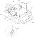
도 1은 본 발명의 일 실시 예에 따른 케이블 테스트 장치를 도시한 사시도,
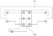
도 2는 도 1에 따른 케이블 테스트 장치의 회로 구성을 도시한 모식도,
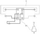
도 3은 도 2에 따른 토글 스위치의 제1 위치에서의 회로 연결을 도시한 모식도,
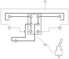
도 4는 도 2에 따른 토글 스위치의 제2 위치에서의 회로 연결을 도시한 모식도,
도 5는 도 2에 따른 토글 스위치의 제3 위치에서의 회로 연결을 도시한 모식도이다.1 is a perspective view showing a cable test apparatus according to an embodiment of the present invention,
FIG. 2 is a schematic diagram showing a circuit configuration of the cable test apparatus according to FIG. 1,
3 is a schematic diagram showing circuit connection at a first position of the toggle switch according to FIG. 2,
Fig. 4 is a schematic diagram showing circuit connection at the second position of the toggle switch according to Fig. 2,
Fig. 5 is a schematic diagram showing the circuit connection at the third position of the toggle switch according to Fig. 2;
이하에서는 도면을 참조하여, 본 발명의 일 실시 예에 따른 케이블 테스트 장치에 대해 상세히 설명하기로 한다.Hereinafter, a cable test apparatus according to an embodiment of the present invention will be described in detail with reference to the drawings.
도 1은 본 발명의 일 실시 예에 따른 케이블 테스트 장치를 도시한 사시도, 도 2는 도 1에 따른 케이블 테스트 장치의 회로 구성을 도시한 모식도이다.FIG. 1 is a perspective view showing a cable test apparatus according to an embodiment of the present invention, and FIG. 2 is a schematic diagram showing a circuit configuration of a cable test apparatus according to FIG.
도 1에 도시된 바와 같이, 본 발명의 케이블 테스트 장치(30)는 다양한 사이즈의 케이블(10)을 검사할 수 있는 장치로, 외관을 형성하는 본체(300)와, 본체(300)의 일면에 구비된 테스트용 부품들로 구성된다.As shown in FIG. 1, the
본체(300) 일면의 일측에는 컨트롤 패널부(310)가 일체로 형성되며, 컨트롤 패널부(310)와 이격된 타측에는 시험 대상 케이블(10)이 결합되는 복수의 케이블 커넥터(330)와, 탐촉자(340)를 연결하는 탐촉자 커넥터(350)와, 검사 모드를 선택할 수 있는 스위치(370)가 구비된다. 컨트롤 패널부(310)에는 탐촉자(340)가 연결되어 본체(300)에 전기적으로 연결되고, 시험 대상 케이블(10)은 케이블 커넥터(330)에 연결되어 이상 유무를 검사하게 된다.A
시험 대상 케이블(10)은 동축 케이블로, 전파가 전달되는 내부 도체(12)와, 내부 도체(12)를 외측에서 감싸는 내부 절연체(14)와, 내부 절연체(14)를 외측에서 감싸는 편조체(16)와, 편조체(16)를 외측에서 감싸는 외부 절연체(18)로 구성된다.The
시험 대상 케이블(10)이 과도하게 꺾이는 등의 환경에서 내부 절연체(14)와 편조체(16)의 사이, 편조체(16)와 외부 절연체(18) 사이 등으로 누설이 발생될 수 있다. 또한, 시험 대상 케이블(10)에 이상이 발생한 경우 내부 도체(12)를 통해 신호가 제대로 전달되지 않을 수 있으므로 누설 여부, '- 접점', '+ 접점'에 이상이 없는지 점검이 필요하다. 이를 위해 케이블 테스트 장치(30)를 사용하게 된다.Leakage may occur between the inner insulator 14 and the braid 16, between the braid 16 and the outer insulator 18 in an environment such as excessive bending of the
본체(300)는 휴대 가능한 박스 형태로, 본체(300)의 일면에는 시험 대상 케이블(10)의 검사를 위한 각종 테스트용 부품들이 구비된다. 본체(300)의 테스트용 부품들이 구비된 면이 아닌 다른 면에는 휴대 시 사용자가 잡고 이동할 수 있는 손잡이(300a)가 구비될 수 있다.The
편의상 도면에는 테스트용 부품들이 본체(300)의 외부에 바로 노출된 형태로 도시하였으나, 별도의 케이스에 본체(300)가 수납된 형태로 케이블 테스트 장치(30)가 구현될 수도 있다. 또는, 테스트용 부품들이 구비된 면을 커버하는 별도의 커버가 구비되어 해당 면을 개폐하는 형태로 구현될 수도 있다.For the sake of convenience, the test components are directly exposed to the outside of the
컨트롤 패널부(310)는 본체(300)의 일면에 일체로 형성되며, 검사 결과를 표시하는 디스플레이(312)와, 시험 항목을 선택할 수 있는 조절기(314)와, 각종 세팅을 위한 복수의 입력 버튼(316)과, 탐촉자(340)가 연결되는 복수의 단자(318)를 포함하여 구성된다.The
디스플레이(312)에는 조절기(314)나 입력 버튼(316)을 통해 변경되는 설정값이나 각종 수치가 표시되며, 시험 대상 케이블(10)의 검사 모드가 표시된다. 또한, 각 검사 모드에 따른 검사 결과 역시 표시된다. 디스플레이(312)를 통해 사용자가 각종 설정값을 확인하며 세팅을 변경할 수 있고, 검사 모드 및 검사 결과를 확인할 수 있다.The
조절기(314)는 검사 항목을 변경하는 기능을 하며, 회전식 다이얼로 구현될 수 있다. 조절기(314)에 의해 검사할 수 있는 검사 모드는 저항, 전류, 전압 등이 있으며, 전류 및 전압 단위에 따른 세기를 선택할 수 있다. 검사 모드는 시험 대상 케이블(10)의 종류에 따라 다르게 설정될 수 있다.The adjuster 314 functions to change the inspection item, and can be implemented with a rotary dial. The test mode that can be checked by the
입력 버튼(316)은 각종 설정값을 변경 및 세팅하는 역할을 하며, 검사 모드나 시험 대상 케이블(10)의 종류에 따라 변경해야 할 설정이 있을 때 사용된다. 조절기(314) 및 입력 버튼(316)에 의해 입력된 값들은 디스플레이(312) 상에 표시된다.The
단자(318)는 복수 개로 구비되며, 검사 모드나 검사 대상 등에 따라 선택적으로 사용될 수 있다. 단자(318)에는 탐촉자(340)가 연결된다.A plurality of
탐촉자(340)는 일단이 컨트롤 패널부(310)의 단자(318)에 연결되고, 타단이 본체(300)에 구비된 탐촉자 커넥터(350)에 결합된다. 탐촉자(340)는 가늘고 뾰족한 탐침(probe) 형태이므로 시험 대상 케이블(10)의 커넥터 핀에 정확하게 접촉시키기가 어려운 문제가 있다.One end of the
종래에는 탐촉자(340)를 시험 대상 케이블(10)의 커넥터 핀에 직접 접촉시켜 검사를 진행하였으므로 검사의 정확도가 떨어지는 문제가 있다.Conventionally, since the
그러나 본 발명에서는 탐촉자(340)를 본체(300)의 탐촉자 커넥터(350)에 연결시키고, 탐촉자 커넥터(350)를 시험 대상 케이블(10)을 본체(300)의 케이블 커넥터(330)에 연결시키며, 탐촉자 커넥터(350)와 케이블 커넥터(330)를 전기적으로 연결하는 회로를 구성함으로써 검사의 정확도를 향상시킨다.However, in the present invention, the
케이블 커넥터(330)는 시험 대상 케이블(10)의 일단 및 타단의 단자가 각각 연결되며, 본체(300) 외부로 노출되지 않도록 구성된 회로에 전기적으로 연결된다. 케이블 커넥터(330)는 단자의 크기가 여러 가지인 시험 대상 케이블(10)을 모두 검사할 수 있도록 크기가 큰 것과 작은 것이 모두 구비되는 것이 바람직하다. 또한, 케이블 커넥터(330)는 시험 대상 케이블(10)의 단자 종류에 맞게 여러 형태로 구비되는 것이 바람직하다. 시험 대상 케이블(10)의 단자 형태는 표준 형태를 따르므로 케이블 커넥터(330) 역시 표준 단자의 형태에 대응하는 형태로 구비될 수 있다.The
탐촉자 커넥터(350)는 전술한 탐촉자(340)가 연결되는 단자로, 탐침 형태의 탐촉자(340)를 감싸는 형태로 구성되어 탐촉자(340)가 전기적으로 안정된 연결 상태를 유지할 수 있도록 한다. 탐촉자 커넥터(350)가 구비됨으로써 검사 시간 동안 사용자가 탐촉자(340)를 잡고 연결 상태를 유지하지 않아도 되므로 검사 시간이 단축되는 효과가 있다. 또한, 탐촉자(340)를 탐촉자 커넥터(350)에 결합시키면 사용자가 분리할 때까지 탐촉자(340)가 임의로 분리되지 않으므로 작업 숙련도가 낮은 사용자도 검사의 오류 없이 쉽게 시험 대상 케이블(10)을 점검할 수 있다.The
도 2에 도시된 바와 같이, 스위치(370)는 3점(three position) 스위치로, 토글 스위치 등으로 구성될 수 있다. 스위치(370)는 3개의 스위칭 포지션을 가지며, 제1 포지션(ⓐ)에서는 '- 접점'을 점검하고, 제2 포지션(ⓑ)에서는 '누설 여부'를 점검한다. 또한, 제3 포지션(ⓒ)에서는 '+ 접점'을 점검한다. 제1 내지 제3 포지션(ⓐ, ⓑ, ⓒ)은 일직선 상에 배치되며, 화살표 방향을 따라 스위치(370)를 이동시키면 제1 포지션(ⓐ)에서 제2 포지션(ⓑ)을 거쳐 제3 포지션으로(ⓒ) 변경된다.As shown in Fig. 2, the
스위치(370) 내부의 회로는 저항계(R)와, -단자 및 +단자를 연결 또는 또는 연결 해제하도록 구성된다. 좀더 상세히 살펴보면, 아래와 같다.The circuit inside the
스위치(370) 내에는 ① 내지 ⑥의 스위칭 회로가 구비되며, ①과 ②, ②와 ③, ④와 ⑤, ⑤와 ⑥이 전기적으로 연결되거나 탈락될 수 있다.The
스위치(370)의 미구동 시 시험 대상 케이블(10)의 일측에 연결된 케이블 커넥터(330)의 +단자는 스위치(370)의 ①에 연결되고, 타측에 연결된 케이블 커넥터(330)의 +단자는 스위치(370)의 ④에 연결된다. 일측 케이블 커넥터(330)의 -단자는 ③에 연결되고, 타측 케이블 커넥터(330)의 -단자는 ⑥에 연결된다. 스위치(370)의 ②는 저항계(R)를 거쳐 ⑤에 연결된다.The positive terminal of the
본 실시 예에서, 저항계(R)는 컨트롤 패널부(310)에서 조절기(314)의 설정을 '저항'으로 설정했을 때를 예로 한 것으로, 검사 항목이 달라지면 회로 상에 표시되는 저항계(R) 역시 달리 표현되는 것이 자명하다.In this embodiment, the ohmmeter R is an example in which the setting of the
이하에서는 각 포지션에서의 회로 연결 관계를 상세히 설명하기로 한다.Hereinafter, the circuit connection relation at each position will be described in detail.
도 3은 도 2에 따른 토글 스위치의 제1 위치에서의 회로 연결을 도시한 모식도이고, 도 4는 도 2에 따른 토글 스위치의 제2 위치에서의 회로 연결을 도시한 모식도이며, 도 5는 도 2에 따른 토글 스위치의 제3 위치에서의 회로 연결을 도시한 모식도이다.Fig. 3 is a schematic diagram showing the circuit connection at the first position of the toggle switch according to Fig. 2, Fig. 4 is a schematic diagram showing circuit connection at the second position of the toggle switch according to Fig. 2, 2 is a schematic diagram showing the circuit connection at the third position of the toggle switch according to the second embodiment.
도 3에 도시된 바와 같이, 스위치(370)의 제1 포지션(ⓐ)에서는 '- 접점'을 점검하므로, 시험 대상 케이블(10)의 일단쪽 -단자와 타단쪽 -단자가 스위치(370)를 통해 연결된다. 즉, 스위치(370) 내에서 ②와 ③이 연결되고, ⑤와 ⑥이 연결되어 시험 대상 케이블(10)의 일단쪽 -단자와 타단쪽 단자가 전기적으로 연결된다.3, the '-contact' is checked at the first position (a) of the
이때, 컨트롤 패널부(310)의 디스플레이(312)에 검사 결과가 표시된다. 예를 들어, 시험 대상 케이블(10)에 이상이 없는 경우, 디스플레이(312)에 표시되는 저항값은 시험 대상 케이블(10)마다 정해진 정상값으로 측정이 될 것이다. 그러나 시험 대상 케이블(10)에 이상이 있는 경우, 디스플레이(312)에 표시되는 저항값은 비정상값으로 표시가 될 것이다. 따라서 디스플레이(312)에 표시되는 저항값으로 시험 대상 케이블(10)의 '- 접점' 검사 결과를 알 수 있다.At this time, the test result is displayed on the
도 4에 도시된 바와 같이, 스위치(370)의 제2 포지션(ⓑ)에서는 '누설 여부'를 점검하므로, 시험 대상 케이블(10)의 일단쪽 단자와 타단쪽 +단자가 스위치(370)를 통해 연결된다. 즉, 스위치(370) ②와 ③이 연결되고, ④와 ⑤가 연결되어 시험 대상 케이블(10)의 일단쪽 -단자와 타단쪽 +단자가 전기적으로 연결된다.As shown in FIG. 4, since the 'leakage' is checked at the second position (b) of the
이때, 컨트롤 패널부(310)의 디스플레이(312)에 검사 결과가 표시된다. 예를 들어, 시험 대상 케이블(10)에 이상이 없는 경우, 디스플레이(312)에 표시되는 저항값은 시험 대상 케이블(10)마다 정해진 정상값으로 측정이 될 것이다. 그러나 시험 대상 케이블(10)에 이상이 있는 경우, 디스플레이(312)에 표시되는 저항값은 비정상값으로 표시가 될 것이다. 따라서 디스플레이(312)에 표시되는 저항값으로 시험 대상 케이블(10)의 '누설 여부' 검사 결과를 알 수 있다.At this time, the test result is displayed on the
도 5에 도시된 바와 같이, 스위치(370)의 제3 포지션(ⓒ)에서는 '+ 접점'을 점검하므로, 시험 대상 케이블(10)의 일단쪽 +단자와 타단쪽 +단자가 스위치(370)를 통해 연결된다. 즉, 스위치(370) 내에서 ①과 ②와 ③이 상호 연결되고, ④와 ⑤가 연결되어 시험 대상 케이블(10)의 일단쪽 +단자와 타단쪽 +단자가 전기적으로 연결된다.The + terminal of the one end of the
이때, 컨트롤 패널부(310)의 디스플레이(312)에 검사 결과가 표시된다. 예를 들어, 시험 대상 케이블(10)에 이상이 없는 경우, 디스플레이(312)에 표시되는 저항값은 시험 대상 케이블(10)마다 정해진 정상값으로 측정이 될 것이다. 그러나 시험 대상 케이블(10)에 이상이 있는 경우, 디스플레이(312)에 표시되는 저항값은 비정상값으로 표시가 될 것이다. 따라서 디스플레이(312)에 표시되는 저항값으로 시험 대상 케이블(10)의 '+ 접점' 검사 결과를 알 수 있다.At this time, the test result is displayed on the
전술한 바와 같이, 본 발명의 케이블 테스트 장치를 사용하면 비숙련 작업자도 검사의 오류 위험 없이 다양한 사이즈의 케이블을 테스트할 수 있어 검사의 신뢰성을 확보할 수 있다. 또한, 휴대가 가능한 케이블 테스트 장치를 제공함으로써 검사의 효율성을 향상시킬 수 있다.As described above, by using the cable test apparatus of the present invention, unskilled operators can test cables of various sizes without risking an error in inspection, thereby ensuring reliability of inspection. Further, by providing a portable cable test apparatus, the inspection efficiency can be improved.
앞에서 설명되고 도면에 도시된 본 발명의 일 실시 예는, 본 발명의 기술적 사상을 한정하는 것으로 해석되어서는 안 된다. 본 발명의 권리범위는 청구범위에 기재된 사항에 의해서만 제한되고, 본 발명의 기술분야에서 통상의 지식을 가진 자는 본 발명의 기술적 사상을 다양한 형태로 개량 및 변경하는 것이 가능하다. 따라서 이러한 개량 및 변경이 통상의 지식을 가진 자에게 자명한 것인 한, 본 발명의 권리범위에 속하게 될 것이다.One embodiment of the present invention described above and shown in the drawings should not be construed as limiting the technical spirit of the present invention. The scope of the present invention is limited only by the matters described in the claims, and those skilled in the art can improve and modify the technical spirit of the present invention in various forms. Accordingly, it is intended that the present invention cover the modifications and variations of this invention provided they come within the scope of the appended claims and their equivalents.
10: 시험 대상 케이블30: 케이블 테스트 장치
300: 본체310: 컨트롤 패널부
330: 케이블 커넥터350: 탐촉자 커넥터
370: 스위치10: Test cable 30: Cable test device
300: main body 310: control panel section
330: Cable connector 350: Transducer connector
370: Switch
Claims (10)
Translated fromKorean상기 본체의 일면에 구비되며, 시험 대상 케이블이 결합되는 복수의 케이블 커넥터와,
상기 케이블 커넥터와 이격되어 상기 본체의 일면에 구비되며, 상기 시험 대상 케이블의 시험 항목을 선택하고 시험 결과를 표시하는 컨트롤 패널부와,
상기 케이블 커넥터와 이격되어 상기 본체의 일면에 구비되되, 전기 회로로 연결되는 탐촉자 커넥터와,
상기 컨트롤 패널부와 상기 탐촉자 커넥터를 전기적으로 연결하는 복수의 탐촉자와,
상기 컨트롤 패널부와 이격되어 상기 본체의 일면에 구비되며, 상기 케이블 커넥터 및 탐촉자 커넥터와 전기적으로 연결되어 상기 시험 대상 케이블의 검사 모드를 선택하는 스위치를 포함하며,
상기 시험 대상 케이블은 동축 케이블인 것을 특징으로 하고,
상기 탐촉자는 탐침(probe) 형태이며, 일단이 상기 컨트롤 패널부의 단자에 연결되고, 타단이 상기 탐촉자 커넥터에 결합되는 것을 특징으로 하며,
상기 탐촉자 커넥터와 상기 케이블 커넥터를 전기적으로 연결하는 회로를 구성함으로써 상기 시험 대상 케이블을 검사하는 것을 특징으로 하는 케이블 테스트 장치.A box-shaped main body having a handle for carrying,
A plurality of cable connectors provided on one side of the main body and to which the cables to be tested are coupled,
A control panel part provided on one side of the main body and spaced apart from the cable connector, for selecting a test item of the cable under test and displaying a test result;
A probe connector disposed on one side of the main body and spaced apart from the cable connector,
A plurality of transducers for electrically connecting the control panel unit and the probe connector,
And a switch provided on one side of the main body and spaced apart from the control panel part and electrically connected to the cable connector and the probe connector to select an inspection mode of the cable under test,
Characterized in that the cable to be tested is a coaxial cable,
Wherein the probe is in the form of a probe and has one end connected to the terminal of the control panel part and the other end coupled to the probe connector,
And the cable to be tested is inspected by constructing a circuit for electrically connecting the probe connector and the cable connector.
상기 스위치는 3개의 포지션(position)을 갖는 토글 스위치인 것을 특징으로 하는 케이블 테스트 장치.The method according to claim 1,
Wherein the switch is a toggle switch having three positions.
상기 스위치는 제1 포지션에서 -접점을, 제2 포지션에서 누설 여부를, 제3 포지션에서 +접점을 테스트하는 것을 특징으로 하는 케이블 테스트 장치.3. The method of claim 2,
Wherein the switch tests the contact at the first position, the leakage at the second position, and the contact at the third position.
상기 스위치는 상기 제1 포지션에서 상기 시험 대상 케이블의 일단쪽 단자와 타단쪽 단자를 전기적으로 연결하는 것을 특징으로 하는 케이블 테스트 장치.The method of claim 3,
Wherein the switch electrically connects the one end terminal and the other end terminal of the cable under test at the first position.
상기 스위치는 상기 제2 포지션에서 상기 시험 대상 케이블의 일단쪽 -단자와 타단쪽 +단자를 전기적으로 연결하는 것을 특징으로 하는 케이블 테스트 장치.The method of claim 3,
Wherein the switch electrically connects the terminal at one end of the cable to be tested with the terminal at the other end in the second position.
상기 스위치는 상기 제3 포지션에서 상기 시험 대상 케이블의 일단쪽 +단자와 타단쪽 +단자를 전기적으로 연결하는 것을 특징으로 하는 케이블 테스트 장치.The method of claim 3,
Wherein the switch electrically connects the + terminal of one end of the cable under test to the + terminal of the other end of the cable at the third position.
상기 컨트롤 패널부는 상기 시험 대상 케이블의 검사 결과를 표시하는 디스플레이와, 저항, 전류, 전압 중 어느 하나의 검사 모드를 선택할 수 있는 조절기와, 상기 탐촉자가 연결되는 복수의 단자를 포함하는 케이블 테스트 장치.7. The method according to any one of claims 4 to 6,
Wherein the control panel unit comprises: a display for displaying an inspection result of the cable under test; a controller capable of selecting one of an inspection mode of resistance, current, and voltage; and a plurality of terminals to which the probe is connected.
상기 제1 내지 제3 포지션에서 상기 시험 대상 케이블의 검사는 상기 조절기의 검사 모드 중 저항 검사 모드인 것을 특징으로 하는 케이블 테스트 장치.8. The method of claim 7,
Wherein the inspection of the test object cable in the first to third positions is the resistance inspection mode during the inspection mode of the regulator.
상기 시험 대상 케이블의 검사 시 상기 시험 대상 케이블이 정상인 경우, 상기 디스플레이에 표시되는 저항값은 상기 시험 대상 케이블마다 정해진 정상값인 것을 특징으로 하는 케이블 테스트 장치.9. The method of claim 8,
Wherein the resistance value displayed on the display is a normal value determined for each cable under test when the cable under test is normal when the cable under test is inspected.
상기 시험 대상 케이블의 검사 시 상기 시험 대상 케이블에 이상이 발생한 경우, 상기 디스플레이에 표시되는 저항값은 상기 정상값과 다른 비정상값인 것을 특징으로 하는 케이블 테스트 장치.10. The method of claim 9,
Wherein a resistance value displayed on the display is an abnormal value different from the normal value when an abnormality occurs in the cable under test when the cable under test is inspected.
Priority Applications (1)
| Application Number | Priority Date | Filing Date | Title |
|---|---|---|---|
| KR1020160096350AKR101853192B1 (en) | 2016-07-28 | 2016-07-28 | Testing device for cable |
Applications Claiming Priority (1)
| Application Number | Priority Date | Filing Date | Title |
|---|---|---|---|
| KR1020160096350AKR101853192B1 (en) | 2016-07-28 | 2016-07-28 | Testing device for cable |
Publications (2)
| Publication Number | Publication Date |
|---|---|
| KR20180013132A KR20180013132A (en) | 2018-02-07 |
| KR101853192B1true KR101853192B1 (en) | 2018-04-27 |
Family
ID=61203907
Family Applications (1)
| Application Number | Title | Priority Date | Filing Date |
|---|---|---|---|
| KR1020160096350AActiveKR101853192B1 (en) | 2016-07-28 | 2016-07-28 | Testing device for cable |
Country Status (1)
| Country | Link |
|---|---|
| KR (1) | KR101853192B1 (en) |
Cited By (1)
| Publication number | Priority date | Publication date | Assignee | Title |
|---|---|---|---|---|
| KR102101317B1 (en) | 2018-11-28 | 2020-05-15 | 유헌규 | Device for testing cable assembly of combat vehicle and testing method using this |
Families Citing this family (5)
| Publication number | Priority date | Publication date | Assignee | Title |
|---|---|---|---|---|
| KR102198930B1 (en)* | 2020-10-19 | 2021-01-06 | 주식회사 라인테크 | Jig device for measuring insulation resistance and withstand voltage |
| KR102419661B1 (en)* | 2021-12-31 | 2022-07-11 | 주식회사 세원전자 | Apparatus for checking the withstand voltage of a connector-connected cable |
| KR20240022322A (en) | 2022-08-11 | 2024-02-20 | 한국전력공사 | Adapter for conneting cable and partial discharge diagnosis system using the same |
| KR102716236B1 (en)* | 2023-03-13 | 2024-10-11 | 주식회사 경신 | Device and method for detecting faulty safety circuit for juction box |
| CN119438831B (en)* | 2025-01-13 | 2025-03-25 | 赣州市金电电子设备有限公司 | A rapid detection device and detection method for changes in electrical properties of a cable when it is heated |
- 2016
- 2016-07-28KRKR1020160096350Apatent/KR101853192B1/enactiveActive
Cited By (1)
| Publication number | Priority date | Publication date | Assignee | Title |
|---|---|---|---|---|
| KR102101317B1 (en) | 2018-11-28 | 2020-05-15 | 유헌규 | Device for testing cable assembly of combat vehicle and testing method using this |
Also Published As
| Publication number | Publication date |
|---|---|
| KR20180013132A (en) | 2018-02-07 |
Similar Documents
| Publication | Publication Date | Title |
|---|---|---|
| KR101853192B1 (en) | Testing device for cable | |
| US4553085A (en) | Coaxial cable tester device | |
| US5477152A (en) | Device for testing continuity and/or short circuits in a cable | |
| JP2005321379A5 (en) | ||
| CN102187243A (en) | Measurement arrangement having a calibration substrate and electronic circuit | |
| JP2007206058A (en) | Connection system | |
| US3205436A (en) | Method and apparatus for measuring impedance increases in the ground or protective ground wires leading to three-wire prong power receptacles | |
| US8724474B2 (en) | Telecommunication port testing apparatus | |
| CN112083309A (en) | Intelligent testing system and method for memory board | |
| AU2018278163A1 (en) | Reflectometry system for detecting faults on a hardened multipoint connector of an electrical network | |
| CN111458540A (en) | Connecting devices and electronic equipment | |
| TWI506280B (en) | Probe module (2) | |
| JP2016070932A (en) | Test system and method | |
| TWI493904B (en) | Radiofrequency characteristic testing equipment | |
| CN106291267A (en) | The electrical property test instrument of spacecraft thermal test multicore cable | |
| CN208140911U (en) | Calibration device for a multifunctional safety intelligent comprehensive tester | |
| KR20220059379A (en) | Cable test device with switch | |
| CN110118907A (en) | Transformer synthesis detection device | |
| GB2444850A (en) | An apparatus for assisting measurement of the resistances of LV ring main circuits | |
| KR102252063B1 (en) | Electromagnetic wave test device for power supply unit | |
| KR101913274B1 (en) | Probe Card Electrical Characteristic Measuring Device | |
| CN214151026U (en) | Calibrating device for network analyzer | |
| JP2012052992A (en) | Cable inspection adapter | |
| CN109521278B (en) | Test tool and method for resistance of inner conductor and outer conductor of coaxial cable | |
| JP5297562B2 (en) | Probe station with improved interconnection |
Legal Events
| Date | Code | Title | Description |
|---|---|---|---|
| A201 | Request for examination | ||
| PA0109 | Patent application | Patent event code:PA01091R01D Comment text:Patent Application Patent event date:20160728 | |
| PA0201 | Request for examination | ||
| E902 | Notification of reason for refusal | ||
| PE0902 | Notice of grounds for rejection | Comment text:Notification of reason for refusal Patent event date:20170601 Patent event code:PE09021S01D | |
| AMND | Amendment | ||
| E601 | Decision to refuse application | ||
| PE0601 | Decision on rejection of patent | Patent event date:20171120 Comment text:Decision to Refuse Application Patent event code:PE06012S01D Patent event date:20170601 Comment text:Notification of reason for refusal Patent event code:PE06011S01I | |
| AMND | Amendment | ||
| PX0901 | Re-examination | Patent event code:PX09011S01I Patent event date:20171120 Comment text:Decision to Refuse Application Patent event code:PX09012R01I Patent event date:20170728 Comment text:Amendment to Specification, etc. | |
| PX0701 | Decision of registration after re-examination | Patent event date:20180122 Comment text:Decision to Grant Registration Patent event code:PX07013S01D Patent event date:20171220 Comment text:Amendment to Specification, etc. Patent event code:PX07012R01I Patent event date:20171120 Comment text:Decision to Refuse Application Patent event code:PX07011S01I Patent event date:20170728 Comment text:Amendment to Specification, etc. Patent event code:PX07012R01I | |
| X701 | Decision to grant (after re-examination) | ||
| PG1501 | Laying open of application | ||
| GRNT | Written decision to grant | ||
| PR0701 | Registration of establishment | Comment text:Registration of Establishment Patent event date:20180423 Patent event code:PR07011E01D | |
| PR1002 | Payment of registration fee | Payment date:20180423 End annual number:3 Start annual number:1 | |
| PG1601 | Publication of registration | ||
| PR1001 | Payment of annual fee | Payment date:20210401 Start annual number:4 End annual number:4 | |
| PR1001 | Payment of annual fee | Payment date:20220330 Start annual number:5 End annual number:5 | |
| PR1001 | Payment of annual fee | Payment date:20230329 Start annual number:6 End annual number:6 |