KR101852847B1 - Engaging apparatus for unmanned aerial vehicle, engaging apparatus for parcel and unmanned aerial vehicle - Google Patents
Engaging apparatus for unmanned aerial vehicle, engaging apparatus for parcel and unmanned aerial vehicleDownload PDFInfo
- Publication number
- KR101852847B1 KR101852847B1KR1020160179822AKR20160179822AKR101852847B1KR 101852847 B1KR101852847 B1KR 101852847B1KR 1020160179822 AKR1020160179822 AKR 1020160179822AKR 20160179822 AKR20160179822 AKR 20160179822AKR 101852847 B1KR101852847 B1KR 101852847B1
- Authority
- KR
- South Korea
- Prior art keywords
- cargo
- insertion holes
- fixing members
- fixing
- unmanned aerial
- Prior art date
- Legal status (The legal status is an assumption and is not a legal conclusion. Google has not performed a legal analysis and makes no representation as to the accuracy of the status listed.)
- Expired - Fee Related
Links
Images


Classifications
- B—PERFORMING OPERATIONS; TRANSPORTING
- B64—AIRCRAFT; AVIATION; COSMONAUTICS
- B64D—EQUIPMENT FOR FITTING IN OR TO AIRCRAFT; FLIGHT SUITS; PARACHUTES; ARRANGEMENT OR MOUNTING OF POWER PLANTS OR PROPULSION TRANSMISSIONS IN AIRCRAFT
- B64D1/00—Dropping, ejecting, releasing or receiving articles, liquids, or the like, in flight
- B64D1/22—Taking-up articles from earth's surface
- B—PERFORMING OPERATIONS; TRANSPORTING
- B64—AIRCRAFT; AVIATION; COSMONAUTICS
- B64C—AEROPLANES; HELICOPTERS
- B64C39/00—Aircraft not otherwise provided for
- B64C39/02—Aircraft not otherwise provided for characterised by special use
- B64C39/024—Aircraft not otherwise provided for characterised by special use of the remote controlled vehicle type, i.e. RPV
- B—PERFORMING OPERATIONS; TRANSPORTING
- B64—AIRCRAFT; AVIATION; COSMONAUTICS
- B64D—EQUIPMENT FOR FITTING IN OR TO AIRCRAFT; FLIGHT SUITS; PARACHUTES; ARRANGEMENT OR MOUNTING OF POWER PLANTS OR PROPULSION TRANSMISSIONS IN AIRCRAFT
- B64D1/00—Dropping, ejecting, releasing or receiving articles, liquids, or the like, in flight
- B64D1/02—Dropping, ejecting, or releasing articles
- B64C2201/128—
- B64D2700/62605—
- B—PERFORMING OPERATIONS; TRANSPORTING
- B64—AIRCRAFT; AVIATION; COSMONAUTICS
- B64U—UNMANNED AERIAL VEHICLES [UAV]; EQUIPMENT THEREFOR
- B64U2101/00—UAVs specially adapted for particular uses or applications
- B64U2101/60—UAVs specially adapted for particular uses or applications for transporting passengers; for transporting goods other than weapons
Landscapes
- Engineering & Computer Science (AREA)
- Aviation & Aerospace Engineering (AREA)
- Connection Of Plates (AREA)
Abstract
Translated fromKoreanDescription
Translated fromKorean본 발명은 무인 항공기용 고정 장치, 화물용 고정 장치 및 무인 항공기에 관한 것으로, 더욱 구체적으로는 배송 가능한 화물의 규격에 대한 제한을 최소화할 수 있으며, 다양한 규격의 화물을 나사산을 이용하여 무인 항공기에 안정적으로 고정(engage)하고 해제(disengage)할 수 있어서 화물의 움직임에 따라서 무인 항공기가 영향을 받는 것을 최소화할 수 있는 무인 항공기용 고정 장치, 화물용 고정 장치 및 무인 항공기에 관한 것이다.The present invention relates to a fixing device for a UAV, a fixing device for a cargo, and a UAV, and more particularly, to a UAV A cargo fixing device, and an unmanned airplane, which can stably engage and disengage, minimizing the influence of the unmanned airplane according to the movement of the cargo.
무인 항공기("드론"으로도 지칭됨)는 조종사가 탑승하지 않은 상태에서 무선 전파의 유도 또는 자동 제어에 의해서 비행 및 조정이 가능한 비행체를 지칭한다. 무인 항공기는 주로 군사용으로 개발 및 사용되었으나, 민간용으로도 개발 및 사용되고 있다.Unmanned aerial vehicles (also referred to as "drones") refer to airborne vehicles that are capable of flying and being adjusted by induction or automatic control of radio waves while the pilot is not on board. Unmanned aerial vehicles were developed and used mainly for military purposes, but they are also being developed and used for civilian use.
민간용 무인 항공기를 사용하는 대표적인 분야는 배송 서비스가 될 것으로 예상된다. 무인 항공기를 이용한 배송 서비스는 미국의 아마존(Amazon.com) 등의 인터넷 쇼핑몰 등에서 시험 운영하고 있으며, 개발 및 성능 시험이 완료되는 대로 보급될 것으로 예상된다.A typical sector using civilian unmanned aerial vehicles is expected to be a shipping service. Unmanned aircrafts are being tested and operated in Internet shopping malls such as Amazon.com in the United States, and are expected to be deployed as soon as development and performance tests are completed.
예컨대 아마존 기술 회사(Amazon Technologies, Inc.)에 의해서 출원되고 2015년 4월 30일 공개된 "UNMANNED AERIAL VEHICLE DELIVERY SYSTEM"이라는 명칭의 미국 특허공개공보 US2015/120094 A1호는 상품을 자동적으로 다양한 목적지로 배송하는 무인 항공기를 개시하고 있다. 미국 특허공개공보 US2015/120094 A1호의 구성에 따르면 화물을 무인 항공기를 통하여 신속하게 배송할 수 있다는 장점이 있다.For example, United States Patent Application Publication No. US2015 / 120094 A1 entitled " UNMANNED AERIAL VEHICLE DELIVERY SYSTEM ", filed by Amazon Technologies, Inc. on April 30, 2015, And the like. According to the structure of U.S. Patent Application Publication No. US2015 / 120094 A1, the cargo can be rapidly delivered through the unmanned airplane.
그러나 미국 특허공개공보 US2015/120094 A1호 및 종래의 무인 항공기에 의한 배송 방식은 미리 지정된 규격의 화물 또는 화물 수용부(container)만을 고정 및 해제할 수 있다는 단점이 있다.However, U.S. Patent Application Publication No. US2015 / 120094 A1 and the conventional unmanned aerial vehicle delivery system have a disadvantage in that only a cargo or a cargo receiving container of a predetermined standard can be fixed and released.
즉 미국 특허공개공보 US2015/120094 A1호의 도 3A 내지 도 3D에 도시된 구성은 앵글 지원 암(angled support arm)의 회전 등에 의해서 화물을 고정하는 구성을 가지므로, 다양한 규격의 화물을 고정 및 해제하는 것이 어렵다는 단점이 있다. 특히 화물의 크기가 앵글 지원 암의 높이보다 큰 경우에는 무인 항공기에 화물을 고정할 수 없다는 단점이 있다. 마찬가지로 미국 특허공개공보 US2015/120094 A1호의 도 3E 내지 도 3G에 도시된 구성은 화물 수용부 내에 화물을 수용하므로 화물 수용부보다 큰 화물을 무인 항공기에 의해서 배송할 수 없다는 단점이 있다.That is, the configuration shown in FIGS. 3A to 3D of U.S. Patent Application Publication No. US2015 / 120094 A1 has a configuration for fixing a cargo by rotation of an angled support arm, There is a drawback that it is difficult. Especially, when the size of the cargo is larger than the height of the angle supporting arm, the cargo can not be fixed to the unmanned airplane. Similarly, the configuration shown in FIGS. 3E to 3G of U.S. Patent Publication No. US2015 / 120094 A1 has a disadvantage in that the cargo can not be delivered by the UAV because the cargo is accommodated in the cargo receiving portion.
한편 한국항공대학교 산학협력단에 의해서 2015년 12월 11일자로 출원되고 2016년 11월 29일자로 등록된 "무인 항공기용 고정 장치 및 무인 항공기"라는 명칭의 한국등록특허 제10-1682572호는 돌출부를 포함하는 화물을 고정할 수 있는 무인 항공기용 고정 장치를 개시하고 있다.Korean Patent No. 10-1682572 entitled " Fixed Units and Unmanned Aircraft for Unmanned Aircraft ", filed on December 11, 2015 and registered on November 29, 2016 by Korea Aerospace University, Which can fix a cargo containing the unmanned aerial vehicle.
한국등록특허 제10-1682572호에 따른 무인 항공기용 고정 장치는 돌출부를 포함하는 화물의 상기 돌출부가 통과하기 위한 개구를 구비하는 본체와, 상기 돌출부를 고정하거나 고정 해제하는 돌출부 고정 부재를 포함한다.Korean Patent No. 10-1682572 includes a main body having an opening through which the protrusion of the cargo including the protrusion passes, and a protrusion fixing member for fixing or releasing the protrusion.
그러나 한국등록특허 제10-1682572호의 구성에 따르면, 화물의 돌출부와 수용부는 연결부에 의해서 연결된다. 따라서 무인 항공기용 고정 장치가 화물을 고정하여 배송하는 경우, 무인 항공기용 고정 장치는 화물을 안정적으로 고정하지 못할 가능성이 있다. 예컨대 화물이 공기 저항에 의해서 움직이거나 또는 무인 항공기의 비행에 따라서 화물이 움직이는 경우, 연결부에 스트레스가 누적되어 연결부가 파손될 가능성이 있다. 또한 화물이 움직이는 것에 따라서 무인 항공기의 비행에 영향을 미칠 수도 있다는 단점도 가진다.However, according to the structure of Korean Patent No. 10-1682572, the projecting portion and the receiving portion of the cargo are connected by the connecting portion. Therefore, when the fixing device for the unmanned aerial vehicle is transported by fixing the cargo, the fixing device for the unmanned aerial vehicle may not be able to stably fix the cargo. For example, if the cargo moves by air resistance or if the cargo moves according to the flight of the UAV, there is a possibility that the connection is damaged due to accumulation of stress in the connection. It also has the disadvantage that the movement of the cargo may affect the flight of the UAV.
본 발명의 목적은 배송 가능한 화물의 규격에 대한 제한을 최소화할 수 있으며, 다양한 규격의 화물을 나사산을 이용하여 무인 항공기에 안정적으로 고정하고 해제할 수 있어서 화물의 움직임에 따라서 무인 항공기가 영향을 받는 것을 최소화할 수 있는 무인 항공기용 고정 장치, 화물용 고정 장치 및 무인 항공기를 제공하는 데 있다.It is an object of the present invention to minimize the limitation on the size of deliverable cargoes and to securely fix and release freight of various sizes to the unmanned airplane by using threads so that the unmanned airplane is affected A fixed device for unmanned aircraft, a fixed device for cargo, and an unmanned airplane.
상기 기술적 과제를 달성하기 위하여, 본 발명은 요부(凹部) 및 상기 요부의 측면에 형성된 복수의 삽입공을 구비하는 화물용 고정 장치가 부착된 화물을 무인 항공기에 고정 또는 고정 해제하기 위한 무인 항공기용 고정 장치로서, 상기 요부에 적어도 일부가 수용되는 본체; 상기 본체에 상기 복수의 삽입공에 대응하여 배치되며, 상기 복수의 삽입공의 표면에 구비된 제1 나사산에 대응하는 제2 나사산을 구비하며, 상기 복수의 삽입공에 삽입되는 복수의 고정 부재; 상기 본체에 배치되며, 상기 복수의 고정 부재가 상기 복수의 삽입공에 삽입되거나 상기 복수의 삽입공으로부터 배출되도록 상기 복수의 고정 부재의 길이 방향을 축으로 상기 복수의 고정 부재를 회전 및 수평 이동하는 구동부; 및 상기 구동부의 동작을 제어하는 제어부를 포함하는 무인 항공기용 고정 장치를 제공한다.According to an aspect of the present invention, there is provided an unmanned airplane for unlocking or unlocking a cargo with a cargo fixing device having a concave portion and a plurality of insertion holes formed on a side surface of the concave portion, A fixing device comprising: a main body, at least a part of which is received in the recess; A plurality of fixing members disposed in the body and corresponding to the plurality of insertion holes and having a second thread corresponding to a first thread provided on a surface of the plurality of insertion holes, the plurality of fixing members being inserted into the plurality of insertion holes; And a plurality of fixing members disposed on the body and rotating and horizontally moving the plurality of fixing members about the longitudinal direction of the plurality of fixing members so that the plurality of fixing members are inserted into the plurality of insertion holes or discharged from the plurality of insertion holes A driving unit; And a control unit for controlling the operation of the driving unit.
또한 본 발명은 화물에 부착되는 화물용 고정 장치로서, 전술한 무인 항공기용 고정 장치의 적어도 일부를 수용하는 요부(凹部)를 구비하는 본체; 및 상기 무인 항공기용 고정 장치에 구비된 복수의 고정 부재가 삽입되도록 상기 복수의 고정 부재에 대응하여 상기 요부의 측면에 형성되며, 표면에 제1 나사산을 구비하는 복수의 삽입공을 구비하는 화물용 고정 장치를 제공한다.The present invention also relates to a cargo fixing device attached to a cargo, comprising: a main body having a recessed portion for accommodating at least a part of the above-described fixing device for an unmanned aerial vehicle; And a plurality of insertion holes formed in a side surface of the recess so as to correspond to the plurality of fixing members so that a plurality of fixing members provided in the fixing device for the unmanned aerial aircraft are inserted, Thereby providing a fixing device.
본 발명에 따른 화물용 고정 장치에 있어서, 상기 화물용 고정 장치는 상기 무인 항공기용 고정 장치를 상기 화물용 고정 장치의 상기 본체에 정렬하기 위한 정렬 유도부를 더 구비할 수 있다.In the cargo fixing device according to the present invention, the cargo fixing device may further include an alignment guide portion for aligning the fixing device for the unmanned aerial vehicle with the main body of the cargo fixing device.
또한 본 발명에 따른 화물용 고정 장치에 있어서, 상기 복수의 삽입공은 상기 본체의 측면을 관통하도록 형성될 수 있다.Further, in the fixing device for a cargo according to the present invention, the plurality of insertion holes may be formed to penetrate the side surface of the main body.
또한 본 발명은 전술한 무인 항공기용 고정 장치를 포함하는 무인 항공기를 제공한다.The present invention also provides an unmanned aerial vehicle including the aforementioned fixing device for an unmanned aerial vehicle.
본 발명에 따르면 배송 가능한 화물의 규격에 대한 제한을 최소화할 수 있으며, 다양한 규격의 화물을 나사산을 이용하여 무인 항공기에 안정적으로 고정하고 해제할 수 있어서 화물의 움직임에 따라서 무인 항공기가 영향을 받는 것을 최소화할 수 있는 무인 항공기용 고정 장치, 화물용 고정 장치 및 무인 항공기를 제공할 수 있다.According to the present invention, it is possible to minimize the restriction on the size of the deliverable cargo, and it is possible to stably fix and release the cargo of various sizes to the unmanned airplane using the thread, so that the unmanned airplane is affected according to the movement of the cargo It is possible to provide a fixing device for a UAV, a fixing device for a cargo, and a UAV that can be minimized.
도 1a 내지 도 1b는 본 발명에 따른 무인 항공기용 고정 장치의 예시적인 구성을 나타내는 도면.
도 2a 내지 도 2d는 본 발명에 따른 무인 항공기용 고정 장치의 단면을 예시적으로 도시한 도면.
도 3a 내지 도 3b는 본 발명에 따른 화물용 고정 장치의 예시적인 구성을 나타내는 도면.
도 4는 본 발명에 따른 화물용 고정 장치가 화물에 고정된 상태를 예시적으로 나타내는 도면.
도 5a 및 도 5d는 본 발명에 따른 무인 항공기용 고정 장치와 화물용 고정 장치가 결합되어 고정된 상태를 예시적으로 나타내는 도면.
도 6은 본 발명에 따른 무인 항공기용 고정 장치의 고정 부재의 형상을 예시적으로 나타내는 도면.
도 7은 본 발명에 따른 무인 항공기의 예시적인 구성을 나타내는 도면.BRIEF DESCRIPTION OF THE DRAWINGS Fig. 1 is a view showing an exemplary configuration of a fastening device for an unmanned aerial vehicle according to the present invention. Fig.
Figures 2a to 2d illustrate in section a cross section of a fastening device for an unmanned aerial vehicle according to the present invention.
Figs. 3A to 3B are views showing an exemplary configuration of a cargo holding device according to the present invention; Fig.
4 is a view exemplarily showing a state in which a cargo fixing device according to the present invention is fixed to a cargo;
FIGS. 5A and 5D are views illustrating a state in which a fixing device for a UAV and a fixing device for a cargo are coupled and fixed according to the present invention; FIG.
6 is a view exemplarily showing a shape of a fixing member of a fixing device for a UAV according to the present invention;
7 is a view showing an exemplary configuration of an unmanned aerial vehicle according to the present invention;
이하, 본 발명의 무인 항공기용 고정 장치, 화물용 고정 장치 및 무인 항공기의 실시예를 첨부한 도면을 참조로 보다 구체적으로 설명한다. 한편 본 발명의 실시예를 설명하기 위한 도면들에서, 설명의 편의를 위해서 실제 구성 중 일부만을 도시하거나 일부를 생략하여 도시하거나 변형하여 도시하거나 또는 축척이 다르게 도시될 수 있다.DETAILED DESCRIPTION OF THE PREFERRED EMBODIMENTS Hereinafter, embodiments of a fixing device for a UAV, a fixing device for a cargo, and an unmanned aerial vehicle according to the present invention will be described in detail with reference to the accompanying drawings. In the drawings for explaining embodiments of the present invention, for the sake of convenience of explanation, only a part of the actual structure is shown or a part thereof is omitted or shown, or the scales may be shown differently.
도 1a 내지 도 1b는 본 발명에 따른 무인 항공기용 고정 장치의 예시적인 구성을 사시도로 나타내는 도면이고, 도 2a 내지 도 2d는 본 발명에 따른 무인 항공기용 고정 장치의 단면을 예시적으로 도시한 도면이고, 도 3a 내지 도 3b는 본 발명에 따른 화물용 고정 장치의 예시적인 구성을 사시도로 나타내는 도면이고, 도 3c는 도 3a의 구성의 단면도를 도시한 도면이다.FIGS. 1A to 1B are perspective views showing an exemplary configuration of a fixing device for a UAV according to the present invention, and FIGS. 2A to 2D are diagrams exemplarily showing cross sections of a fixing device for a UAV according to the present invention 3A and 3B are perspective views showing an exemplary configuration of a cargo fixing apparatus according to the present invention, and FIG. 3C is a sectional view of the configuration of FIG. 3A.
도 1a 내지 도 3b를 참조하여, 본 발명에 따른 무인 항공기용 고정 장치를 보다 구체적으로 설명한다.1A to 3B, a securing apparatus for a UAV according to the present invention will be described in more detail.
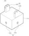
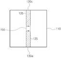
도 2a 및 도 2b를 참조하면, 본 발명에 따른 무인 항공기용 고정 장치(100)는 본체(110)와, 복수의 고정 부재(130)와, 구동부(150)와, 제어부(170)를 포함한다. 또한 도 1a 및 도 1b를 참조하면, 본 발명에 따른 무인 항공기용 고정 장치(100)는 무인 항공기 결합부(190)를 더 포함할 수 있다. 또한 도 3a 내지 도 3c를 참조하면, 본 발명에 따른 화물용 고정 장치(200)는 요부(215)를 구비하는 본체(210)와, 요부(215)의 측면에 형성된 복수의 삽입공(230)을 구비한다. 도 3c를 참조하면,복수의 삽입공(230)은 그 표면에 제1 나사산(235)을 구비한다.2A and 2B, a
본체(110)는 도 3a 또는 도 3b에 도시된 화물용 고정 장치(200)의 요부(215)에 적어도 일부가 수용되도록 구성된다. 본체(110)는 예컨대 복수의 고정 부재(130)(예컨대 도 2a에 도시된 130a 내지 130d), 구동부(150)(예컨대 도 2a에 도시된 150a 내지 150d) 및 제어부(170)를 수용하기 위한 케이스 형태일 수 있다. 한편 본체(110)의 복수의 고정 부재(130)(예컨대 도 2a에 도시된 130a 내지 130d)가 배치된 부분에는 복수의 고정 부재(130a 내지 130d)의 각각의 표면에 구비된 제2 나사산(135)에 대응하여 나사산이 형성될 수 있으나, 나사산이 형성되지 않더라도 무방하다.The
도 1a 및 도 3a를 참조하면, 바람직하게는, 본체(110)의 적어도 일부, 예컨대 본체(110)의 하부는 요부(215)에 수용될 수 있도록 요부(215)의 형상에 대응하는 형상을 가진다. 예컨대 도 3a에 도시된 바와 같이 요부(215)가 4각 기둥(구체적인 예로 정육면체) 형상인 경우, 본체(110)의 적어도 일부, 예컨대 본체(110)의 하부는 도 1a에 도시된 바와 같이 요부(215)의 형상에 대응하는 4각 기둥(구체적인 예로 정육면체) 형상을 가질 수 있다.1A and 3A, at least a portion of the
요부(215)는 4각 기둥 형상 이외에도 예컨대 원 기둥 형상, 타원 기둥 형상, 각기둥 형상, 원뿔 형상, 타원뿔 형상, 각뿔 형상, 반구 형상 및 전술한 형상들 중 적어도 2개가 조합된 형상 및 전술한 형상들 중 일부가 절단된 형상 중 어느 하나의 형상을 가지는 공간을 구비할 수도 있다. 본체(110)의 적어도 일부, 예컨대 본체(110)의 하부는 이러한 요부(215)가 구비하는 공간에 대응하는 형상을 가지는 것이 바람직하다.The
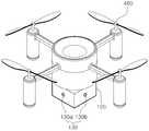
도 5a 및 도 5b는 본 발명에 따른 무인 항공기용 고정 장치와 화물용 고정 장치가 결합되어 고정된 상태를 예시적으로 나타내는 도면이다.5A and 5B are views illustrating a state in which a fixing device for a UAV and a fixing device for a cargo are coupled and fixed according to the present invention.
도 5a를 참조하면, 화물용 고정 장치(200)의 본체(210)의 요부(215)에 무인 항공기용 고정 장치(100)의 본체(110)의 하부가 수용되며, 복수의 고정 부재(130a 내지 130d)는 화물용 고정 장치(200)의 본체(210)의 요부(210)의 측면에 형성된 복수의 삽입공(도 3c의 230a 내지 230d)에 삽입되어 고정된다. 보다 구체적으로는 전술하듯이 복수의 삽입공(230)의 표면에 구비된 제1 나사산(235)과 복수의 고정 부재(130a 내지 130d) 각각의 표면에 구비되며 제1 나사산(235)에 대응하는 제2 나사산(135)에 의해서 복수의 고정 부재(130a 내지 130d)는 복수의 삽입공(도 3c의 230a 내지 230d)에 삽입되어 고정된다.5A, a
한편 복수의 삽입공(230a 내지 230d)은 도 3c에 도시되듯이 본체(210)의 측면을 관통하도록 형성될 수도 있다. 이 경우, 복수의 고정 부재(130a 내지 130d)는 복수의 삽입공(230a 내지 230d)에 삽입되어 본체(210)의 외표면의 외부까지 돌출될 수도 있다.The plurality of
그러나 본체(110)의 적어도 일부가 화물용 고정 장치(200)의 요부(215)에 수용될 수 있고 또한 복수의 고정 부재(130a 내지 130d)가 화물용 고정 장치(200)의 복수의 삽입공(230a 내지 230d)에 제1 나사산(235)과 제2 나사산(135)을 통하여 삽입될 수 있도록 구성된다면, 본체(110)의 적어도 일부, 예컨대 본체(110)의 하부의 형상과 요부(215)가 구비하는 공간의 형상은 달라도 무방하다. 예컨대 도 1a에 도시된 바와 같이 예컨대 본체(110)의 하부가 4각 기둥(구체적인 예로 정육면체) 형상인 경우라도, 도 3b에 도시되는 바와 같이, 요부(215)는 원기둥 형상일 수도 있다. 또는 도 1b에 도시된 바와 같이 예컨대 본체(110)의 하부가 원기둥 형상인 경우라도, 도 3a에 도시되는 바와 같이, 요부(215)는 사각 기둥, 구체적인 예로 정육면체 형상일 수도 있다.However, at least a portion of the
다만 본체(110)의 하부의 형상과 요부(215)의 형상이 다를 경우 또는 본체(110)의 하부의 형상과 요부(215)의 형상이 동일하더라도 본체(110)가 요부(215)에 정확하게 수용되도록 그리고 복수의 고정 부재(130a 내지 130d)가 화물용 고정 장치(200)의 복수의 삽입공(230a 내지 230d)에 제1 나사산(235)과 제2 나사산(135)을 이용하여 삽입될 수 있도록, 본 발명에 따른 무인 항공기용 고정 장치(100)는 정렬부를 더 포함할 수 있다.However, even if the shape of the lower portion of the
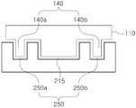
도 5c는 본 발명에 따른 무인 항공기용 고정 장치와 화물용 고정 장치가 결합되어 고정된 상태를 예시적으로 나타내는 도면이다. 도 5c를 참조하면, 본체(110)의 하부에는 정렬부(140)가 구비된다.5C is a view illustrating a state in which a fixing device for a UAV and a fixing device for a cargo are coupled and fixed according to the present invention. Referring to FIG. 5C, an
정렬부(140)는 도 3b에 도시된 화물용 고정 장치(200)에 구비된 정렬 유도부(250)에 대응하는 형상을 가진다. 예컨대 도 3b에 도시되듯이, 정렬 유도부(250)가 2개의 오목 형상의 구조(250a, 250b)를 포함하는 경우, 도 5c에 도시되듯이, 정렬부(140)는 오목 형상의 구조(250a, 250b) 각각에 삽입될 수 있도록 볼록 형상의 구조(140a, 140b)를 포함한다.The
도 5c에 도시되듯이, 볼록 형상의 구조(140a, 140b)와 오목 형상의 구조(250a, 250b)가 정렬되어 삽입되면, 본체(110)의 하부가 요부(215)에 수용될 수 있다.As shown in FIG. 5C, when the
도 5d는 본 발명에 따른 무인 항공기용 고정 장치와 화물용 고정 장치가 결합되어 고정된 상태를 예시적으로 나타내는 도면이다.FIG. 5D is a view illustrating a state in which a fixing device for a UAV and a fixing device for a cargo are coupled and fixed according to the present invention.
도 5d에서 요부(215)는 각기둥 형상 중 하부가 절단된 형상을 가진다. 본체(110)의 적어도 일부, 예컨대 본체(110)의 하부는 이러한 요부(215)가 구비하는 공간에 대응하여 각기둥 형상 중 하부가 절단된 형상을 가진다.5D, the
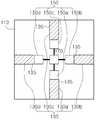
도 2a 내지 도 2b를 참조하면, 복수의 고정 부재(130a 내지 130d)는 본체(110)에 화물용 고정 장치(200)의 복수의 삽입공(230a 내지 230d)에 대응하여 배치되며, 복수의 삽입공(230a 내지 230d)의 표면에 구비된 제1 나사산(235)에 대응하는 제2 나사산(135)을 구비한다. 복수의 고정 부재(130a 내지 130d)는 제1 나사산(235)과 제2 나사산(135)을 통하여 복수의 삽입공(230a 내지 230d)에 삽입 및 고정될 수 있도록 구성된다. 도 2a는 복수의 고정 부재(130a 내지 130d)가 구동부(150)에 의해서 회전 및 수평 이동되기 전의 상태를 도시하며, 도 2b는 복수의 고정 부재(130a 내지 130d)가 구동부(150)에 의해서 회전 및 수평 이동된 상태, 즉 복수의 고정 부재(130a 내지 130d)가 복수의 삽입공(230a 내지 230d)에 삽입되어 고정된 상태의 무인 항공기용 고정 장치(100)의 상태를 도시한다.2A to 2B, a plurality of fixing
복수의 고정 부재(130a 내지 130d)는 도 2a 내지 도 2b에서는 4개로 도시되었지만, 복수의 고정 부재의 개수는 이에 한정되지 않는다. 예컨대 복수의 고정 부재의 개수는 2개, 3개, 4개, 5개 및 6개 중 어느 하나일 수도 있다.Although the plurality of fixing
복수의 고정 부재(130a 내지 130d) 각각은 예컨대 바(bar) 형상일 수 있다.Each of the plurality of fixing
도 6은 본 발명에 따른 무인 항공기용 고정 장치의 고정 부재의 형상을 예시적으로 나타내는 도면이다.6 is a view exemplarily showing the shape of a fixing member of a fixing device for a UAV according to the present invention.
예컨대 도 3c에 도시되듯이, 복수의 삽입공(230a 내지 230d)은 그 표면에 제1 나사산(235)을 구비한다. 도 6에 도시되듯이, 복수의 고정 부재(130a 내지 130d)의 표면에는 제1 나사산(235)에 대응하는 제2 나사산(135)을 구비한다. 따라서 복수의 고정 부재(130a 내지 130d)의 제2 나사산(135)과 복수의 삽입공(230a 내지 230d)의 제1 나사산(235)이 체결되는 것에 의해서, 보다 더 안정적으로 화물의 움직임을 방지할 수 있다.For example, as shown in FIG. 3C, the plurality of
다시 도 2a 내지 도 2b를 참조하면, 구동부(150)는 본체(110)에 배치되며, 복수의 고정 부재(130a 내지 130d)가 복수의 삽입공(230a 내지 230d)에 삽입되거나 복수의 삽입공(230a 내지 230d)으로부터 배출되도록 복수의 고정 부재(130a 내지 130d)의 길이 방향을 축으로 복수의 고정 부재(130a 내지 130d)를 회전 및 수평 이동한다. 구동부(150)는 예컨대 서보 모터를 이용하여 구현될 수 있다.2A and 2B, the driving
예컨대 구동부(150)는 복수의 고정 부재(130a 내지 130d)에 대응하는 복수의 제1 구동부(150a 내지 150d)를 포함한다.For example, the driving
복수의 제1 구동부(150a 내지 150d) 각각은 복수의 고정 부재(130a 내지 130d) 중 대응하는 고정 부재가 복수의 삽입공(230a 내지 230d) 중 대응하는 삽입공으로 삽입되거나 또는 대응하는 삽입공으로부터 배출되도록 복수의 고정 부재(130a 내지 130d) 중 대응하는 고정 부재를 회전 및 수평 이동한다.Each of the plurality of
예컨대 제1 구동부(150a)는 고정 부재(150a)가 삽입공(230a)으로 삽입되거나 또는 삽입공(230a)으로부터 배출되도록 고정 부재(130a)를 회전 및 수평 이동한다.For example, the
마찬가지로, 제1 구동부(150b)는 고정 부재(150b)가 삽입공(230b)으로 삽입되거나 또는 삽입공(230b)으로부터 배출되도록 고정 부재(130b)를 회전 및 수평 이동하고, 제1 구동부(150c)는 고정 부재(150c)가 삽입공(230c)으로 삽입되거나 또는 삽입공(230c)으로부터 배출되도록 고정 부재(130c)를 회전 및 수평 이동하고, 제1 구동부(150d)는 고정 부재(150d)가 삽입공(230d)으로 삽입되거나 또는 삽입공(230d)으로부터 배출되도록 고정 부재(130d)를 회전 및 수평 이동한다.Similarly, the
제어부(170)는 구동부(150)의 동작을 제어한다. 예컨대 구동부(150)가 복수의 제1 구동부(150a 내지 150d)를 포함하는 경우, 제어부(170)는 복수의 제1 구동부(150a 내지 150d) 각각을 연동하여 제어한다. 따라서 복수의 고정 부재(130a 내지 130d)는 복수의 제1 구동부(150a 내지 150d)에 의해서 동시에 복수의 삽입공(230a 내지 230d)으로 삽입되거나 또는 복수의 삽입공(230a 내지 230d)으로부터 배출될 수 있다.The
한편 구동부(150)는 도 2c 내지 도 2d를 참조하면, 제2 구동부(155)를 하나 이상 포함할 수도 있다.On the other hand, referring to FIG. 2C to FIG. 2D, the driving
제2 구동부(155)는 복수의 고정 부재(130a 내지 130d) 중 대응하는 2개의 고정 부재(예컨대 130a, 130c)가 복수의 삽입공(230a 내지 230d) 중 대응하는 2개의 삽입공(예컨대 230a, 230c)으로 삽입되거나 대응하는 2개의 삽입공(예컨대 230a, 230c)으로부터 배출되도록 복수의 고정 부재(130a 내지 130d) 중 대응하는 2개의 고정 부재(예컨대 130a, 130c)를 회전 및 수평 이동한다.The
도 2c는 고정 부재(예컨대 130a, 130c)가 제2 구동부(155)에 의해서 이동되기 전의 상태를 도시하며, 도 2d는 고정 부재(예컨대 130a, 130c)가 제2 구동부(155)에 의해서 이동된 상태, 즉 고정 부재(예컨대 130a, 130c)가 복수의 삽입공(예컨대 230a, 230c)에 삽입된 상태의 무인 항공기용 고정 장치(100)의 상태를 도시한다. 도 2c 내지 도 2c에서 제어부(170) 등의 구성은 도시를 생략한다.FIG. 2C shows a state before the fixing members (for example, 130a and 130c) are moved by the
도 2a 내지 도 2b에 도시된 구성과는 다르게, 도 2c 내지 도 2d에 도시된 제2 구동부(155)는 동시에 2개의 고정 부재(예컨대 130a, 130c)를 회전 및 수평 이동하므로, 구동부(150)의 구성을 보다 단순하게 할 수 있다.The
본 발명에 따른 무인 항공기용 고정 장치(100)는 예컨대 무인 항공기에 장착되거나 또는 탈착될 수 있다. 이를 위해서, 도 1a 내지 도 1b를 참조하면, 본 발명에 따른 무인 항공기용 고정 장치(100)는 무인 항공기 결합부(190)를 더 포함할 수 있다.The securing
무인 항공기 결합부(190)는 본체(110)의 상면에 배치되며, 무인 항공기에 탈착 가능하다. 무인 항공기 결합부(190)는 예컨대 도 1a에 도시되듯이 본체(110)의 상면의 양 측부에 배치되는 한 쌍의 체결 구조(190a 내지 190b)를 포함하도록 구현될 수 있다. 한 쌍의 체결 구조(190a 내지 190b) 각각은 예컨대 나사 등을 통하여 무인 항공기에 체결될 수 있는 구성을 가진다.The unmanned aerial
한편 도 1b를 참조하면, 무인 항공기 결합부(190)는 본체(110)의 상부의 중앙부에 배치되는 1개의 체결 구조(190c)를 포함할 수도 있다. 즉 본 발명에 따른 무인 항공기용 고정 장치(100)는 도 1a에 도시된 예와는 달리 도 1b에 도시되듯이 1개의 체결 구조(190c)만을 이용하여 무인 항공기에 체결될 수도 있다.Referring to FIG. 1B, the unmanned aerial
한편 무인 항공기 결합부(190)는 도 1a 및 도 1b를 통하여 예시적인 구조를 설명하였지만, 기타 다른 형태로 무인 항공기용 고정 장치(100)를 무인 항공기에 결합하는 것도 가능하다.Although the unmanned aerial
이상에서 설명한 바와 같이 본 발명에 따른 무인 항공기용 고정 장치에 따르면, 배송 가능한 화물의 규격에 대한 제한을 최소화할 수 있으며, 다양한 규격의 화물을 나사산을 이용하여 무인 항공기에 안정적으로 고정하고 해제할 수 있어서 화물의 움직임에 따라서 무인 항공기가 영향을 받는 것을 최소화할 수 있다.As described above, according to the fixing apparatus for an unmanned aerial vehicle according to the present invention, it is possible to minimize the restriction on the size of the deliverable cargo and to reliably fix and release the cargo of various sizes to the unmanned airplane using the thread Therefore, it is possible to minimize the influence of the unmanned airplane according to the movement of the cargo.
도 3a 내지 도 3b를 참조하면, 전술하듯이 본 발명에 따른 화물용 고정 장치(200)는 요부(215)를 구비하는 본체(210)와, 요부(215)의 측면에 형성된 복수의 삽입공(230)을 구비한다.3A and 3B, the
본 발명에 따른 화물용 고정 장치(200)는 전술한 무인 항공기용 고정 장치(100)와 조합되어서 화물을 고정하는 것이며, 화물(도 4의 300)에 부착될 수 있다.The
도 4는 본 발명에 따른 화물용 고정 장치가 화물에 고정된 상태를 예시적으로 나타내는 도면이다.4 is a view illustrating a state in which a cargo fixing device according to the present invention is fixed to a cargo.
도 4를 참조하면, 본 발명에 따른 화물용 고정 장치(200)는 화물(300)에 부착된다. 화물용 고정 장치(200)를 화물(300)에 부착하는 방식은 예컨대 접착 테이프를 이용하여 부착하거나, 또는 도 4에 도시되듯이 화물용 고정 장치(200)가 화물(300)을 고정하는 고정 부재(270a 내지 270d)를 구비하고 고정 부재(270a 내지 270d)에 의해서 화물(300)을 지지하는 방식을 이용할 수도 있다. 고정 부재(270a 내지 270d)의 형상과 개수는 다양하게 변형될 수 있다.Referring to FIG. 4, the
본 발명에 따른 화물용 고정 장치(200)에 대한 설명은 본 발명에 따른 화물용 고정 장치에 대한 설명을 참조할 수 있으므로 상세한 설명을 생략한다.The description of the
이상에서 설명한 바와 같이 본 발명에 따른 화물용 고정 장치에 따르면, 배송 가능한 화물의 규격에 대한 제한을 최소화할 수 있으며, 다양한 규격의 화물을 나사산을 이용하여 무인 항공기에 안정적으로 고정하고 해제할 수 있어서 화물의 움직임에 따라서 무인 항공기가 영향을 받는 것을 최소화할 수 있다.As described above, according to the cargo locking apparatus of the present invention, it is possible to minimize the limitation on the size of the deliverable cargo, and to stably fix and release the cargo of various sizes on the unmanned airplane using the thread It is possible to minimize the influence of the unmanned airplane according to the movement of the cargo.
도 7은 본 발명에 따른 무인 항공기의 예시적인 구성을 나타내는 도면이다.7 is a diagram showing an exemplary configuration of an unmanned aerial vehicle according to the present invention.
본 발명에 따른 무인 항공기(400)의 구성은 전술한 본 발명에 따른 무인 항공기용 고정 장치가 무인 항공기에 일체형으로 장착된 것을 제외하면 본 발명에 따른 무인 항공기용 고정 장치와 동일하므로 상세한 설명을 생략한다.The configuration of the
또한 본 발명에 따른 무인 항공기의 구성은 예시적인 것일 뿐이며, 예컨대 회전 날개가 8개인 옥타드론 등 다양한 형태를 가질 수 있다.The configuration of the unmanned aerial vehicle according to the present invention is merely an example, and may have various forms such as an octadron having eight rotary blades.
이상에서 설명한 바와 같이 본 발명에 따른 무인 항공기에 따르면, 나사산을 이용하여 다양한 규격의 화물을 안정적으로 고정하고 해제할 수 있어서 화물의 움직임에 따라서 무인 항공기가 영향을 받는 것을 최소화할 수 있다.As described above, according to the unmanned aerial vehicle according to the present invention, it is possible to stably lock and unlock various types of cargo using threads, thereby minimizing the influence of the unmanned airplane according to the movement of the cargo.
비록 본 발명의 구성이 구체적으로 설명되었지만 이는 단지 본 발명을 예시적으로 설명한 것에 불과한 것으로, 본 발명이 속하는 기술분야에서 통상의 지식을 가지는 자라면 본 발명의 본질적인 특성에서 벗어나지 않는 범위 내에서 다양한 변형이 가능할 것이다.Although the present invention has been described in detail, it should be understood that the present invention is not limited thereto. Those skilled in the art will appreciate that various modifications may be made without departing from the essential characteristics of the present invention. Will be possible.
따라서 본 명세서에 개시된 실시예들은 본 발명을 한정하기 위한 것이 아니라 설명하기 위한 것이고, 이러한 실시예에 의하여 본 발명의 사상과 범위가 한정되는 것은 아니다. 본 발명의 범위는 아래의 청구범위에 의해 해석되어야 하며, 그와 동등한 범위 내에 있는 모든 기술은 본 발명의 권리범위에 포함되는 것으로 해석되어야 할 것이다.Therefore, the embodiments disclosed in the present specification are intended to illustrate rather than limit the present invention, and the scope and spirit of the present invention are not limited by these embodiments. The scope of the present invention should be construed according to the following claims, and all the techniques within the scope of equivalents should be construed as being included in the scope of the present invention.
본 발명에 따르면 배송 가능한 화물의 규격에 대한 제한을 최소화할 수 있으며, 다양한 규격의 화물을 나사산을 이용하여 무인 항공기에 안정적으로 고정하고 해제할 수 있어서 화물의 움직임에 따라서 무인 항공기가 영향을 받는 것을 최소화할 수 있는 무인 항공기용 고정 장치, 화물용 고정 장치 및 무인 항공기를 제공할 수 있다.According to the present invention, it is possible to minimize the restriction on the size of the deliverable cargo, and it is possible to stably fix and release the cargo of various sizes to the unmanned airplane using the thread, so that the unmanned airplane is affected according to the movement of the cargo It is possible to provide a fixing device for a UAV, a fixing device for a cargo, and a UAV that can be minimized.
100: 무인 항공기용 고정 장치110: 본체
130: 고정 부재135: 제2 나사산
140: 정렬부150: 구동부
170: 제어부190: 무인 항공기 결합부
200: 화물용 고정 장치210: 본체
215: 요부230: 삽입공
235: 제1 나사산250: 정렬 유도부
270a 내지 270d: 고정 부재300: 화물
400: 무인 항공기100: Fixing device for unmanned aerial vehicle 110:
130: fixing member 135: second thread
140: alignment unit 150:
170: control unit 190: unmanned aerial vehicle coupling unit
200: Fixture for cargo 210: Main body
215: recess 230: insertion hole
235: first screw thread 250:
270a to 270d: Fixing member 300: Cargo
400: Unmanned aircraft
Claims (15)
Translated fromKorean상기 요부에 적어도 일부가 수용되는 본체;
상기 본체에 상기 복수의 삽입공에 대응하여 배치되며, 상기 복수의 삽입공의 표면에 구비된 제1 나사산에 대응하는 제2 나사산을 구비하며, 상기 복수의 삽입공에 삽입되는 복수의 고정 부재;
상기 본체에 배치되며, 상기 복수의 고정 부재가 상기 복수의 삽입공에 삽입되거나 상기 복수의 삽입공으로부터 배출되도록 상기 복수의 고정 부재의 길이 방향을 축으로 상기 복수의 고정 부재를 회전 및 수평 이동하는 구동부; 및
상기 구동부의 동작을 제어하는 제어부
를 포함하는 무인 항공기용 고정 장치.A fixing device for an unmanned airplane for fixing or unlocking a cargo with a cargo fixing device having a concave portion and a plurality of insertion holes formed on a side surface of the concave portion,
A main body at least partially accommodated in the recess;
A plurality of fixing members disposed in the body and corresponding to the plurality of insertion holes and having a second thread corresponding to a first thread provided on a surface of the plurality of insertion holes, the plurality of fixing members being inserted into the plurality of insertion holes;
And a plurality of fixing members disposed on the body and rotating and horizontally moving the plurality of fixing members about the longitudinal direction of the plurality of fixing members such that the plurality of fixing members are inserted into the plurality of insertion holes or discharged from the plurality of insertion holes A driving unit; And
A control unit for controlling the operation of the driving unit
And a locking device for locking the unmanned aircraft.
상기 본체의 하부의 적어도 일부는 상기 요부에 수용되도록 상기 요부의 형상에 대응하는 형상을 가지는 것인 무인 항공기용 고정 장치.The method according to claim 1,
Wherein at least a part of the lower portion of the main body has a shape corresponding to the shape of the recessed portion so as to be accommodated in the recessed portion.
상기 본체의 하부에 구비되며, 상기 화물용 고정 장치에 구비된 정렬 유도부에 대응하는 형상을 가지는 정렬부를 더 포함하는 무인 항공기용 고정 장치.The method according to claim 1,
Further comprising an aligning portion provided at a lower portion of the main body and having a shape corresponding to the alignment guide portion provided in the cargo fixing device.
상기 구동부는,
상기 복수의 고정 부재 중 대응하는 고정 부재가 상기 복수의 삽입공 중 대응하는 삽입공으로 삽입되거나 상기 대응하는 삽입공으로부터 배출되도록 상기 복수의 고정 부재 중 대응하는 고정 부재를 회전 및 수평 이동하는 복수의 제1 구동부
를 포함하는 것인 무인 항공기용 고정 장치.The method according to claim 1,
The driving unit includes:
A plurality of fixing members, which rotate and horizontally move the corresponding fixing members of the plurality of fixing members such that corresponding fixing members among the plurality of fixing members are inserted into corresponding insertion holes of the plurality of insertion holes or discharged from the corresponding insertion holes, 1 driver
Wherein the securing means includes a securing means for securing the unmanned aircraft.
상기 제어부는 상기 복수의 제1 구동부 각각을 연동하여 제어하는 것인 무인 항공기용 고정 장치.The method according to claim 1,
Wherein the control unit controls the plurality of first driving units in association with each other.
상기 구동부는,
상기 복수의 고정 부재 중 대응하는 2개의 고정 부재가 상기 복수의 삽입공 중 대응하는 2개의 삽입공으로 삽입되거나 상기 대응하는 2개의 삽입공으로부터 배출되도록 상기 복수의 고정 부재 중 대응하는 2개의 고정 부재를 회전 및 수평 이동하는 제2 구동부
를 하나 이상 포함하는 것인 무인 항공기용 고정 장치.The method according to claim 1,
The driving unit includes:
Wherein two corresponding fixing members among the plurality of fixing members are inserted into corresponding two insertion holes of the plurality of insertion holes or are ejected from the corresponding two insertion holes, And a second driving unit
Wherein said at least one locking device comprises at least one locking device.
상기 복수의 고정 부재의 개수는 2개 내지 6개 중 어느 하나인 것인 무인 항공기용 고정 장치.The method according to claim 1,
Wherein the number of the plurality of fixing members is any one of 2 to 6.
상기 복수의 고정 부재는 봉(bar) 형상인 것인 무인 항공기용 고정 장치.The method according to claim 1,
Wherein the plurality of fastening members are bar-shaped.
상기 본체의 상면에 배치되며, 상기 무인 항공기에 탈착 가능한 무인 항공기 결합부
를 더 포함하는 무인 항공기용 고정 장치.The method according to claim 1,
And an unmanned airplane engaging portion disposed on an upper surface of the main body,
Further comprising: a securing device for an unmanned aerial vehicle.
상기 무인 항공기 결합부는 상기 본체의 상면의 양 측부에 배치되는 한 쌍의 체결구조를 포함하는 것인 무인 항공기용 고정 장치.10. The method of claim 9,
Wherein the unmanned aerial vehicle coupling portion includes a pair of fastening structures disposed on both sides of an upper surface of the main body.
상기 무인 항공기 결합부는 상기 본체의 상부의 중앙부에 배치되는 체결 구조를 포함하는 것인 무인 항공기용 고정 장치.10. The method of claim 9,
Wherein the unmanned aerial vehicle coupling portion includes a fastening structure disposed at a central portion of an upper portion of the main body.
제1항 내지 제11항 중 어느 한 항에 따른 무인 항공기용 고정 장치의 적어도 일부를 수용하는 요부(凹部)를 구비하는 본체; 및
상기 무인 항공기용 고정 장치에 구비된 복수의 고정 부재가 삽입되도록 상기 복수의 고정 부재에 대응하여 상기 요부의 측면에 형성되며, 표면에 제1 나사산을 구비하는 복수의 삽입공
을 구비하는 화물용 고정 장치.As a cargo fixing device attached to a cargo,
A main body having recesses for accommodating at least a part of the securing device for an unmanned aerial vehicle according to any one of claims 1 to 11; And
A plurality of insertion holes formed in a side surface of the recessed portion corresponding to the plurality of fixing members so that a plurality of fixing members provided in the fixing device for the unmanned aerial aircraft are inserted,
(10).
상기 화물용 고정 장치는 상기 무인 항공기용 고정 장치를 상기 화물용 고정 장치의 상기 본체에 정렬하기 위한 정렬 유도부를 더 구비하는 것인 화물용 고정 장치.13. The method of claim 12,
Wherein the cargo fixing device further comprises an alignment guide portion for aligning the fixing device for the unmanned aerial vehicle with the main body of the cargo fixing device.
상기 복수의 삽입공은 상기 본체의 측면을 관통하도록 형성되는 것인 화물용 고정 장치.13. The method of claim 12,
And the plurality of insertion holes are formed to penetrate the side surface of the main body.
Priority Applications (1)
| Application Number | Priority Date | Filing Date | Title |
|---|---|---|---|
| KR1020160179822AKR101852847B1 (en) | 2016-12-27 | 2016-12-27 | Engaging apparatus for unmanned aerial vehicle, engaging apparatus for parcel and unmanned aerial vehicle |
Applications Claiming Priority (1)
| Application Number | Priority Date | Filing Date | Title |
|---|---|---|---|
| KR1020160179822AKR101852847B1 (en) | 2016-12-27 | 2016-12-27 | Engaging apparatus for unmanned aerial vehicle, engaging apparatus for parcel and unmanned aerial vehicle |
Publications (1)
| Publication Number | Publication Date |
|---|---|
| KR101852847B1true KR101852847B1 (en) | 2018-04-27 |
Family
ID=62081600
Family Applications (1)
| Application Number | Title | Priority Date | Filing Date |
|---|---|---|---|
| KR1020160179822AExpired - Fee RelatedKR101852847B1 (en) | 2016-12-27 | 2016-12-27 | Engaging apparatus for unmanned aerial vehicle, engaging apparatus for parcel and unmanned aerial vehicle |
Country Status (1)
| Country | Link |
|---|---|
| KR (1) | KR101852847B1 (en) |
Cited By (1)
| Publication number | Priority date | Publication date | Assignee | Title |
|---|---|---|---|---|
| CN112660390A (en)* | 2020-12-29 | 2021-04-16 | 西北工业大学 | A cargo platform for unmanned aerial vehicle |
Citations (4)
| Publication number | Priority date | Publication date | Assignee | Title |
|---|---|---|---|---|
| US20150120094A1 (en) | 2013-10-26 | 2015-04-30 | Amazon Technologies, Inc. | Unmanned aerial vehicle delivery system |
| KR101682572B1 (en) | 2015-12-11 | 2016-12-05 | 한국항공대학교산학협력단 | Parcel engaging apparatus for unmanned aerial vehicle and unmanned aerial vehicle |
| KR101682574B1 (en) | 2015-12-18 | 2016-12-05 | 한국항공대학교산학협력단 | Engaging apparatus of unmanned aerial vehicle and unmanned aerial vehicle |
| KR101682570B1 (en) | 2015-12-14 | 2016-12-05 | 한국항공대학교산학협력단 | Supporting apparatus for unmanned aerial vehicle and method of controlling the same |
- 2016
- 2016-12-27KRKR1020160179822Apatent/KR101852847B1/ennot_activeExpired - Fee Related
Patent Citations (4)
| Publication number | Priority date | Publication date | Assignee | Title |
|---|---|---|---|---|
| US20150120094A1 (en) | 2013-10-26 | 2015-04-30 | Amazon Technologies, Inc. | Unmanned aerial vehicle delivery system |
| KR101682572B1 (en) | 2015-12-11 | 2016-12-05 | 한국항공대학교산학협력단 | Parcel engaging apparatus for unmanned aerial vehicle and unmanned aerial vehicle |
| KR101682570B1 (en) | 2015-12-14 | 2016-12-05 | 한국항공대학교산학협력단 | Supporting apparatus for unmanned aerial vehicle and method of controlling the same |
| KR101682574B1 (en) | 2015-12-18 | 2016-12-05 | 한국항공대학교산학협력단 | Engaging apparatus of unmanned aerial vehicle and unmanned aerial vehicle |
Cited By (1)
| Publication number | Priority date | Publication date | Assignee | Title |
|---|---|---|---|---|
| CN112660390A (en)* | 2020-12-29 | 2021-04-16 | 西北工业大学 | A cargo platform for unmanned aerial vehicle |
Similar Documents
| Publication | Publication Date | Title |
|---|---|---|
| KR101682572B1 (en) | Parcel engaging apparatus for unmanned aerial vehicle and unmanned aerial vehicle | |
| KR101852845B1 (en) | Engaging apparatus for unmanned aerial vehicle, engaging apparatus for parcel and unmanned aerial vehicle | |
| JP7285847B2 (en) | unmanned aerial vehicle | |
| US8939409B2 (en) | Adaptor system for deploying small satellites | |
| EP3439955B1 (en) | Foldable aircraft with protective cage | |
| KR101682574B1 (en) | Engaging apparatus of unmanned aerial vehicle and unmanned aerial vehicle | |
| KR101852844B1 (en) | Engaging apparatus for unmanned aerial vehicle and unmanned aerial vehicle | |
| CN108137170B (en) | satellites including optical photographic instruments | |
| CN106005369B (en) | A kind of unmanned plane | |
| US11505318B2 (en) | Container retention and release apparatus having integral swaybrace and retention features | |
| KR101852847B1 (en) | Engaging apparatus for unmanned aerial vehicle, engaging apparatus for parcel and unmanned aerial vehicle | |
| US20200164983A1 (en) | Container retention and release apparatus having integral swaybrace and retention features | |
| WO2020123256A1 (en) | Weight-triggered locking feature | |
| CN110920900A (en) | Floor fastening assembly | |
| KR102002952B1 (en) | A device for damage protection for a drone | |
| KR102508583B1 (en) | Flight formation maintenance apparatus | |
| US4646994A (en) | Spacecraft support and separation system | |
| US9802712B2 (en) | Quick release system for a coupling and drogue assembly | |
| ES2685664T3 (en) | Flip flap system | |
| KR101826194B1 (en) | Parcel container for unmanned aerial vehicle and unmanned aerial vehicle | |
| RU2522787C1 (en) | Device of fixing in fold position of wing panels of unmanned aerial vehicle | |
| US20090294592A1 (en) | Fastening Device for an Aircraft Interior Equipment Component | |
| JP2010247651A (en) | Landing device of flying body | |
| KR101591408B1 (en) | Apparatus for mounting detetor sensor of UAV | |
| US11377235B2 (en) | Method and apparatus for satellite deployment |
Legal Events
| Date | Code | Title | Description |
|---|---|---|---|
| PA0109 | Patent application | St.27 status event code:A-0-1-A10-A12-nap-PA0109 | |
| PA0201 | Request for examination | St.27 status event code:A-1-2-D10-D11-exm-PA0201 | |
| PE0902 | Notice of grounds for rejection | St.27 status event code:A-1-2-D10-D21-exm-PE0902 | |
| P11-X000 | Amendment of application requested | St.27 status event code:A-2-2-P10-P11-nap-X000 | |
| P13-X000 | Application amended | St.27 status event code:A-2-2-P10-P13-nap-X000 | |
| E701 | Decision to grant or registration of patent right | ||
| PE0701 | Decision of registration | St.27 status event code:A-1-2-D10-D22-exm-PE0701 | |
| GRNT | Written decision to grant | ||
| PR0701 | Registration of establishment | St.27 status event code:A-2-4-F10-F11-exm-PR0701 | |
| PR1002 | Payment of registration fee | St.27 status event code:A-2-2-U10-U11-oth-PR1002 Fee payment year number:1 | |
| PG1601 | Publication of registration | St.27 status event code:A-4-4-Q10-Q13-nap-PG1601 | |
| P22-X000 | Classification modified | St.27 status event code:A-4-4-P10-P22-nap-X000 | |
| PN2301 | Change of applicant | St.27 status event code:A-5-5-R10-R13-asn-PN2301 St.27 status event code:A-5-5-R10-R11-asn-PN2301 | |
| R18-X000 | Changes to party contact information recorded | St.27 status event code:A-5-5-R10-R18-oth-X000 | |
| PR1001 | Payment of annual fee | St.27 status event code:A-4-4-U10-U11-oth-PR1001 Fee payment year number:4 | |
| PR1001 | Payment of annual fee | St.27 status event code:A-4-4-U10-U11-oth-PR1001 Fee payment year number:5 | |
| P22-X000 | Classification modified | St.27 status event code:A-4-4-P10-P22-nap-X000 | |
| R17-X000 | Change to representative recorded | St.27 status event code:A-5-5-R10-R17-oth-X000 | |
| PC1903 | Unpaid annual fee | St.27 status event code:A-4-4-U10-U13-oth-PC1903 Not in force date:20230424 Payment event data comment text:Termination Category : DEFAULT_OF_REGISTRATION_FEE | |
| PC1903 | Unpaid annual fee | St.27 status event code:N-4-6-H10-H13-oth-PC1903 Ip right cessation event data comment text:Termination Category : DEFAULT_OF_REGISTRATION_FEE Not in force date:20230424 | |
| P22-X000 | Classification modified | St.27 status event code:A-4-4-P10-P22-nap-X000 |