KR101851572B1 - Method for producing electrode plate group unit for lithium-ion capacitor, and lithium-ion capacitor - Google Patents
Method for producing electrode plate group unit for lithium-ion capacitor, and lithium-ion capacitorDownload PDFInfo
- Publication number
- KR101851572B1 KR101851572B1KR1020127033725AKR20127033725AKR101851572B1KR 101851572 B1KR101851572 B1KR 101851572B1KR 1020127033725 AKR1020127033725 AKR 1020127033725AKR 20127033725 AKR20127033725 AKR 20127033725AKR 101851572 B1KR101851572 B1KR 101851572B1
- Authority
- KR
- South Korea
- Prior art keywords
- electrode plate
- negative electrode
- positive electrode
- lithium
- plate group
- Prior art date
- Legal status (The legal status is an assumption and is not a legal conclusion. Google has not performed a legal analysis and makes no representation as to the accuracy of the status listed.)
- Expired - Fee Related
Links
Images


Classifications
- H—ELECTRICITY
- H01—ELECTRIC ELEMENTS
- H01G—CAPACITORS; CAPACITORS, RECTIFIERS, DETECTORS, SWITCHING DEVICES, LIGHT-SENSITIVE OR TEMPERATURE-SENSITIVE DEVICES OF THE ELECTROLYTIC TYPE
- H01G11/00—Hybrid capacitors, i.e. capacitors having different positive and negative electrodes; Electric double-layer [EDL] capacitors; Processes for the manufacture thereof or of parts thereof
- H01G11/84—Processes for the manufacture of hybrid or EDL capacitors, or components thereof
- H—ELECTRICITY
- H01—ELECTRIC ELEMENTS
- H01G—CAPACITORS; CAPACITORS, RECTIFIERS, DETECTORS, SWITCHING DEVICES, LIGHT-SENSITIVE OR TEMPERATURE-SENSITIVE DEVICES OF THE ELECTROLYTIC TYPE
- H01G11/00—Hybrid capacitors, i.e. capacitors having different positive and negative electrodes; Electric double-layer [EDL] capacitors; Processes for the manufacture thereof or of parts thereof
- H01G11/04—Hybrid capacitors
- H01G11/06—Hybrid capacitors with one of the electrodes allowing ions to be reversibly doped thereinto, e.g. lithium ion capacitors [LIC]
- H—ELECTRICITY
- H01—ELECTRIC ELEMENTS
- H01G—CAPACITORS; CAPACITORS, RECTIFIERS, DETECTORS, SWITCHING DEVICES, LIGHT-SENSITIVE OR TEMPERATURE-SENSITIVE DEVICES OF THE ELECTROLYTIC TYPE
- H01G11/00—Hybrid capacitors, i.e. capacitors having different positive and negative electrodes; Electric double-layer [EDL] capacitors; Processes for the manufacture thereof or of parts thereof
- H01G11/22—Electrodes
- H01G11/26—Electrodes characterised by their structure, e.g. multi-layered, porosity or surface features
- H01G11/28—Electrodes characterised by their structure, e.g. multi-layered, porosity or surface features arranged or disposed on a current collector; Layers or phases between electrodes and current collectors, e.g. adhesives
- H—ELECTRICITY
- H01—ELECTRIC ELEMENTS
- H01G—CAPACITORS; CAPACITORS, RECTIFIERS, DETECTORS, SWITCHING DEVICES, LIGHT-SENSITIVE OR TEMPERATURE-SENSITIVE DEVICES OF THE ELECTROLYTIC TYPE
- H01G11/00—Hybrid capacitors, i.e. capacitors having different positive and negative electrodes; Electric double-layer [EDL] capacitors; Processes for the manufacture thereof or of parts thereof
- H01G11/22—Electrodes
- H01G11/30—Electrodes characterised by their material
- H01G11/50—Electrodes characterised by their material specially adapted for lithium-ion capacitors, e.g. for lithium-doping or for intercalation
- H—ELECTRICITY
- H01—ELECTRIC ELEMENTS
- H01G—CAPACITORS; CAPACITORS, RECTIFIERS, DETECTORS, SWITCHING DEVICES, LIGHT-SENSITIVE OR TEMPERATURE-SENSITIVE DEVICES OF THE ELECTROLYTIC TYPE
- H01G11/00—Hybrid capacitors, i.e. capacitors having different positive and negative electrodes; Electric double-layer [EDL] capacitors; Processes for the manufacture thereof or of parts thereof
- H01G11/66—Current collectors
- H—ELECTRICITY
- H01—ELECTRIC ELEMENTS
- H01G—CAPACITORS; CAPACITORS, RECTIFIERS, DETECTORS, SWITCHING DEVICES, LIGHT-SENSITIVE OR TEMPERATURE-SENSITIVE DEVICES OF THE ELECTROLYTIC TYPE
- H01G11/00—Hybrid capacitors, i.e. capacitors having different positive and negative electrodes; Electric double-layer [EDL] capacitors; Processes for the manufacture thereof or of parts thereof
- H01G11/74—Terminals, e.g. extensions of current collectors
- H—ELECTRICITY
- H01—ELECTRIC ELEMENTS
- H01G—CAPACITORS; CAPACITORS, RECTIFIERS, DETECTORS, SWITCHING DEVICES, LIGHT-SENSITIVE OR TEMPERATURE-SENSITIVE DEVICES OF THE ELECTROLYTIC TYPE
- H01G11/00—Hybrid capacitors, i.e. capacitors having different positive and negative electrodes; Electric double-layer [EDL] capacitors; Processes for the manufacture thereof or of parts thereof
- H01G11/78—Cases; Housings; Encapsulations; Mountings
- H01G11/82—Fixing or assembling a capacitive element in a housing, e.g. mounting electrodes, current collectors or terminals in containers or encapsulations
- H—ELECTRICITY
- H01—ELECTRIC ELEMENTS
- H01G—CAPACITORS; CAPACITORS, RECTIFIERS, DETECTORS, SWITCHING DEVICES, LIGHT-SENSITIVE OR TEMPERATURE-SENSITIVE DEVICES OF THE ELECTROLYTIC TYPE
- H01G11/00—Hybrid capacitors, i.e. capacitors having different positive and negative electrodes; Electric double-layer [EDL] capacitors; Processes for the manufacture thereof or of parts thereof
- H01G11/84—Processes for the manufacture of hybrid or EDL capacitors, or components thereof
- H01G11/86—Processes for the manufacture of hybrid or EDL capacitors, or components thereof specially adapted for electrodes
- H—ELECTRICITY
- H01—ELECTRIC ELEMENTS
- H01G—CAPACITORS; CAPACITORS, RECTIFIERS, DETECTORS, SWITCHING DEVICES, LIGHT-SENSITIVE OR TEMPERATURE-SENSITIVE DEVICES OF THE ELECTROLYTIC TYPE
- H01G9/00—Electrolytic capacitors, rectifiers, detectors, switching devices, light-sensitive or temperature-sensitive devices; Processes of their manufacture
- H01G9/0029—Processes of manufacture
- H—ELECTRICITY
- H01—ELECTRIC ELEMENTS
- H01G—CAPACITORS; CAPACITORS, RECTIFIERS, DETECTORS, SWITCHING DEVICES, LIGHT-SENSITIVE OR TEMPERATURE-SENSITIVE DEVICES OF THE ELECTROLYTIC TYPE
- H01G9/00—Electrolytic capacitors, rectifiers, detectors, switching devices, light-sensitive or temperature-sensitive devices; Processes of their manufacture
- H01G9/004—Details
- H01G9/04—Electrodes or formation of dielectric layers thereon
- H01G9/048—Electrodes or formation of dielectric layers thereon characterised by their structure
- Y—GENERAL TAGGING OF NEW TECHNOLOGICAL DEVELOPMENTS; GENERAL TAGGING OF CROSS-SECTIONAL TECHNOLOGIES SPANNING OVER SEVERAL SECTIONS OF THE IPC; TECHNICAL SUBJECTS COVERED BY FORMER USPC CROSS-REFERENCE ART COLLECTIONS [XRACs] AND DIGESTS
- Y02—TECHNOLOGIES OR APPLICATIONS FOR MITIGATION OR ADAPTATION AGAINST CLIMATE CHANGE
- Y02E—REDUCTION OF GREENHOUSE GAS [GHG] EMISSIONS, RELATED TO ENERGY GENERATION, TRANSMISSION OR DISTRIBUTION
- Y02E60/00—Enabling technologies; Technologies with a potential or indirect contribution to GHG emissions mitigation
- Y02E60/13—Energy storage using capacitors
Landscapes
- Engineering & Computer Science (AREA)
- Power Engineering (AREA)
- Microelectronics & Electronic Packaging (AREA)
- Chemical & Material Sciences (AREA)
- Materials Engineering (AREA)
- Manufacturing & Machinery (AREA)
- Electric Double-Layer Capacitors Or The Like (AREA)
- Connection Of Batteries Or Terminals (AREA)
- Secondary Cells (AREA)
Abstract
Translated fromKorean
Description
Translated fromKorean본 발명은, 리튬 이온 캐패시터용 극판군 유닛의 제조 방법 및 그 극판군 유닛을 구비한 리튬 이온 캐패시터에 관한 것이다.The present invention relates to a method for manufacturing a lithium ion capacitor pole plate group unit and a lithium ion capacitor including the electrode plate group unit.
대용량 캐패시터(예를 들면, 500F 이상)로서, 리튬 이온 전지의 이점과 전기 이중층 캐패시터의 이점을 조합한 리튬 이온 캐패시터가 개발되어 있다. 최근 개발이 진행되고 있는 리튬 이온 캐패시터는, 일반적으로, 정극 활물질에 활성탄, 부극 활물질에 리튬 이온을 흡장ㆍ방출 가능한 탄소재가 사용되고 있다. 리튬 이온 캐패시터는, 미리 부극판에 리튬 이온이 흡장 또는 도프되어 있음으로써, 부극 전위가 통상의 전기 이중층 캐패시터(약 -1V∼-1.35V)보다 낮게 유지된다(약 -3V). 그로 인해, 셀의 사용 전압 범위를 높게 할 수 있고(약 2.2V∼3.8V), 또한 정극 충방전 기구로서, 통상의 전기 이중층 캐패시터에서 이용되는 음이온의 흡착에 더하여, 양이온의 흡착도 이용할 수 있으므로, 용량을 원리적으로 2배 취출할 수 있다. 또한 리튬 이온 캐패시터는, 리튬 이온 전지에 비해 용량은 작지만, 내부 저항이 작아 출력 특성의 점에서 우수한 동시에, 수명이 길다고 하는 이점이 있다[일본 특허 출원 공개 제2010-141217호(특허문헌 1)]. 특허문헌 1에 기재된 구조에서는, 복수의 탭을 이용하여 집전판과 집전 부재를 접속하고 있다.As a large-capacity capacitor (for example, 500 F or more), a lithium-ion capacitor having a combination of the advantages of a lithium-ion battery and the advantages of an electric double-layer capacitor has been developed. The lithium ion capacitor, which is being developed in recent years, generally uses activated carbon as a positive electrode active material, and carbon materials capable of storing and releasing lithium ions as a negative electrode active material. In the lithium ion capacitor, the negative electrode potential is kept lower than the normal electric double layer capacitor (about -1 V to-1.35 V) because lithium ions are previously stored or doped in the negative electrode plate (about -3 V). As a result, it is possible to increase the operating voltage range of the cell (about 2.2 V to 3.8 V), and as the positive electrode charging and discharging mechanism, adsorption of positive ions can be used in addition to the adsorption of anions used in ordinary electric double layer capacitors , The capacity can be extracted in principle twice. Further, the lithium ion capacitor is advantageous in that it has a smaller capacity than the lithium ion battery but has a small internal resistance, which is excellent in terms of output characteristics and has a long life span (Japanese Patent Application Laid-Open No. 2010-141217 (Patent Document 1) ]. In the structure described in
이러한 리튬 이온 캐패시터를 제조하는 경우에, 구리박으로 이루어지는 부극 집전체와 구리로 이루어지는 부극 집전 부재를 확실하게 용접하기 위해, YAG 레이저 광을 사용한 레이저 용접을 이용하고 있는 것이 있다[일본 특허 출원 공개 제2010-93178호(특허문헌 2)]. 특허문헌 2에 기재된 구조에서는, 탭을 이용하는 일 없이, 부극 집전체에 부극 집전 부재를 직접 용접하고 있다.In manufacturing such a lithium ion capacitor, laser welding using YAG laser light is used in order to surely weld the negative electrode current collector made of copper foil and the negative electrode current collector made of copper (Japanese Patent Application Laid- 2010-93178 (Patent Document 2)]. In the structure described in
그러나 특허문헌 2에 개시되어 있는 YAG 레이저 광이나 CO2 레이저 광을 사용하는 용접 기술에서는, 레이저 광의 집광 에너지가 높아, 레이저가 조사되어 있는 부분의 금속이 증발하고, 그 반력에 의해 열쇠 구멍과 같이 녹는, 이른바 「키홀」이 발생하므로, 용융 금속이 비산하거나(스패터), 용융 구멍에 가스가 들어가 블로우 홀을 형성하게 되는 경우가 있어, 용접 결함이 발생하기 쉽다. 또한, YAG 레이저 광이나 CO2 레이저 광은 스폿 직경이 작은 것이나, 레이저 광의 집광용 렌즈의 온도 상승에 의해 초점이 변화되므로, 용접 위치가 어긋나기 쉬워, 용접의 품질에 편차가 발생하기 쉽다. 리튬 이온 캐패시터를 제조하는 경우, 집전 부재와 극판의 집전체의 용접이 불충분하면, 용접부의 저항이 증대되어, 캐패시터의 성능이 저하되게 된다는 문제가 있다.However, in the welding technique using the YAG laser light or the CO2 laser light disclosed in
본 발명의 목적은, 집전 부재와 극판을 확실하게 용접하여, 용접부의 저항이 낮고, 용융 금속에 의한 단락이 발생하지 않는 리튬 이온 캐패시터용 극판군 유닛을 제조하는 방법 및 리튬 이온 캐패시터를 제공하는 것에 있다.It is an object of the present invention to provide a method for manufacturing a lithium ion capacitor unit for a lithium ion capacitor in which the current collecting member and the electrode plate are securely welded so that the resistance of the welded portion is low and short- have.
상기 목적에 더하여, 본 발명의 목적은, 사전 충전 동작에 있어서, 금속 리튬이 확실하게 흡장되는 리튬 이온 캐패시터용 극판군 유닛의 제조 방법 및 리튬 이온 캐패시터를 제공하는 것에 있다.In addition to the above objects, an object of the present invention is to provide a method for manufacturing a lithium ion capacitor unit for a lithium ion capacitor, in which metal lithium is securely stored in a pre-charging operation, and a lithium ion capacitor.
본 발명의 제조 방법에 의해 제조하는 리튬 이온 캐패시터용 극판군 유닛은, 기본적인 구성에, 알루미늄박(정극 집전체)에 정극 활물질 합제가 도착(塗着)된 정극판과, 구리박(부극 집전체)에 부극 활물질 합제가 도착된 부극판이 세퍼레이터를 개재하여 적층된 적층체를 권회하여 이루어지는 극판군과, 정극판의 알루미늄박에 전기적으로 접속된 알루미늄으로 이루어지는 정극 집전 부재와, 부극판의 구리박에 전기적으로 접속된 금속 재료로 이루어지는 부극 집전 부재와, 금속 리튬과, 부극 집전 부재와 전기적으로 접속되어 이온 투과성을 갖고, 또한 금속 리튬을 보유 지지하는 구조를 갖는 구리박으로 이루어지는 지지체를 구비한 금속 리튬 지지 부재를 구비하고 있다.The lithium-ion capacitor pole plate group unit manufactured by the manufacturing method of the present invention is basically composed of a positive electrode plate in which a positive electrode active material mixture is applied to an aluminum foil (positive electrode collector), a copper foil A positive electrode current collecting member made of aluminum electrically connected to the aluminum foil of the positive electrode plate; and a positive electrode collector member made of copper foil of the negative electrode plate, A negative electrode current collector made of a metal material electrically connected to the positive electrode current collector, a metal lithium electrode, and a metal having a support made of a copper foil, which is electrically connected to the negative electrode current collector and has ion permeability, And a lithium support member.
금속 리튬 지지 부재는, 극판군 내 또는 극판군에 인접하여 정극판과 전기적으로 절연된 상태에서 배치되어 있고, 금속 리튬이, 부극판의 부극 활물질 합제 중의 부극 활물질에 흡장(프리도프)됨으로써 구리박만이 잔존하도록 되어 있다.The metallic lithium supporting member is disposed in the electrode plate group or in the state of being electrically insulated from the positive electrode plate adjacent to the electrode plate group and metal lithium is stored (pre-doped) in the negative electrode active material in the negative electrode active material mixture of the negative electrode plate, .
본 발명의 리튬 이온 캐패시터용 극판군 유닛의 제조 방법에서는, 부극판으로서는, 부극 활물질 합제의 도포층을 따라 구리박의 미도포 시공부가 남겨진 것을 준비한다. 또한 정극판으로서는, 정극 활물질 합제의 도포층을 따라 알루미늄박의 미도포 시공부가 남겨진 것을 준비한다. 그리고 극판군을, 부극판의 미도포 시공부와 정극판의 미도포 시공부가 각각 역방향으로 세퍼레이터보다 외측으로 돌출되도록 구성한다. 이와 같이 하여 구성한 극판군의 부극판의 미도포 시공부 및 지지체의 단부 상에 부극 집전 부재를 얹은 상태에서, 직접 집광형 반도체 레이저 장치를 사용하여 용접한다.In the manufacturing method of the electrode plate unit for a lithium ion capacitor of the present invention, as the negative electrode plate, the uncoated portion of the copper foil is prepared along the coating layer of the negative electrode active material mixture. Further, as the positive electrode plate, an uncoated portion of the aluminum foil is left along the coating layer of the positive electrode active material mixture. And the electrode plate group is configured such that the uncoated portions of the negative electrode plate and the uncoated portions of the positive electrode plate are projected outwardly from the separator in opposite directions. The negative electrode current collecting type semiconductor laser device is used to weld the negative electrode current collecting member and the negative electrode current collecting member on the end portions of the negative electrode coating portion and the supporting member of the electrode plate constructed as described above.
본 발명에서 사용하는 직접 집광형 반도체 레이저 장치(Direct Diode Laser:DDL)라 함은, 고효율의 발진이 가능한 레이저 다이오드(LD)를 광원으로 하는 반도체 레이저 광원의 레이저 광을 직접 집광하여 출력하는 반도체 레이저 장치이며(예를 들면, 코히런트ㆍ재팬 가부시끼가이샤나 laserline사가 판매하고 있는 고출력 반도체 레이저 장치 등), 레이저 광에 의한 전도열로 금속을 녹이는 용접이 가능하고, 또한 연속적으로 레이저 광을 발생할 수 있는 것이다. 그로 인해, 이른바 키홀이 발생할 일은 없고, 용접 금속이 비산되거나, 블로우 홀을 형성하는 일이 없어, 부극 집전 부재를 효율적으로 용융시킬 수 있고, 확실하게 용접을 행하는 것이 가능해져, 용접부의 저항이 커지는 것을 확실하게 방지할 수 있다. 또한, 용융 금속에 의한 비산에 의한 스패터가 적으므로, 리튬 이온 캐패시터용 극판군 유닛을 용기에 수납한 경우에, 용기와의 단락이 발생할 가능성도 없어진다. 또한, 본 발명에서는, 권회된 극판군의 부극판의 미도포 시공부에 직접 용접을 행하기 때문에, 용접 면적이 커지므로, 접촉 저항을 보다 작게 할 수 있다. 특히, 본 발명에서는, 구리박으로 이루어지는 금속 리튬 지지 부재의 지지체도, 부극 집전 부재에 함께 용접하므로, 금속 리튬 지지 부재와 부극 집전 부재를 용접부의 저항을 크게 하는 일 없이 확실하게 용접할 수 있다. 그로 인해, 사전 충전시에, 부극판의 부극 활물질 합제 중의 부극 활물질에 금속 리튬을 확실하게 흡장시킬 수 있다. 또한, 금속 리튬이 흡장된 후에, 잔존하는 지지재가 낙하하는 것을 방지할 수 있다.The direct condensing type semiconductor laser device (DDL) used in the present invention is a semiconductor laser device that directly condenses laser light of a semiconductor laser light source using a laser diode (LD) capable of high- (For example, a high-power semiconductor laser device sold by Kohrant Japan Co., Ltd., LaserLine Co., Ltd.), welding which can dissolve metal by conduction heat by laser light, and which can continuously generate laser light will be. As a result, there is no occurrence of a so-called keyhole, no welding metal is scattered, no blowholes are formed, the negative electrode current collector can be efficiently melted, welding can be performed reliably, Can be reliably prevented. Furthermore, since the spatter caused by scattering of molten metal is small, there is no possibility that a short circuit with the container occurs when the electrode plate unit for lithium ion capacitor is housed in the container. Further, in the present invention, since the welding is directly performed on the uncoated portion of the negative electrode plate of the wound electrode plate group, the welding area is increased, so that the contact resistance can be further reduced. In particular, in the present invention, since the support of the metallic lithium supporting member made of copper foil is also welded together with the negative electrode current collector, the metallic lithium supporting member and the negative electrode current collector can be securely welded without increasing the resistance of the welded portion. Therefore, at the time of pre-charging, metal lithium can be stored in the negative electrode active material in the negative electrode active material mixture of the negative electrode with reliability. Further, it is possible to prevent the remaining support material from dropping after the metal lithium is occluded.
또한, 사용하는 직접 집광형 반도체 레이저 장치로부터 출력하는 레이저 광의 파장과 파워는, 부극 집전 부재를 효율적으로 용융시킬 수 있는 것을 선택하면 좋다. 또한, 본 발명의 직접 집광형 반도체 레이저 장치에는, 출력 레이저 광을 광 파이버에 집광시켜 처리를 용이하게 한 파이버 도광형 반도체 레이저 장치(FOLD)도 포함되는 것이다.The wavelength and the power of the laser light output from the direct condensing type semiconductor laser device to be used may be selected so as to efficiently melt the negative electrode current collecting member. Further, the direct-light-converging type semiconductor laser device of the present invention also includes a fiber light-guiding semiconductor laser device (FOLD) that converges the output laser light onto the optical fiber to facilitate the processing.
본 발명의 부극측에 사용하는 직접 집광형 반도체 레이저 장치는, 정극 집전 부재 및 정극판에 사용하고 있는 알루미늄의 용접도 가능하므로, 부극 집전 부재와 부극판 뿐만 아니라, 정극 집전 부재와 정극판에 대해서도 마찬가지의 용접 장치를 사용하여 용접을 행할 수 있다. 즉, 극판군의 정극판의 미도포 시공부 상에 정극 집전 부재를 얹은 상태에서, 레이저 광을 연속적으로 발생하는 직접 집광형 반도체 레이저 장치를 사용하여, 레이저 광을 정극 집전 부재에 연속 조사하여 정극 집전 부재를 국부적으로 용융하고, 용융 금속에 의해 정극판의 미도포 시공부와 정극 집전 부재를 용접할 수 있다. 따라서, 1대의 직접 집광형 반도체 레이저 장치를 사용하여, 부극측 및 정극측의 용접 작업을 행할 수 있어, 생산 효율이 향상된다.The direct light collecting type semiconductor laser device used for the negative electrode side of the present invention can also weld aluminum used for the positive electrode collector and the positive electrode plate so that not only the negative electrode collector and the negative electrode plate but also the positive electrode collector member and the positive electrode plate The welding can be performed using the same welding apparatus. That is, by using a direct-light-converging type semiconductor laser device that continuously generates laser light in a state in which the positive electrode collector is placed on the uncoated portion of the positive plate of the electrode plate group, the laser light is continuously applied to the positive collector, The current collecting member is melted locally and the uncoated portion of the positive electrode plate and the positive electrode collector are welded by the molten metal. Therefore, welding can be performed on the negative electrode side and the positive electrode side by using one direct-light-converging type semiconductor laser device, and the production efficiency is improved.
본 발명의 제조 방법에 있어서 용접을 행하는 경우, 용융 금속이 극판군의 가장 직경 방향 외측에 위치하는 극판층을 넘어 직경 방향 외측으로 연장되지 않도록 하는 것이 좋다. 본 발명의 제조 방법으로 제조된 리튬 이온 캐패시터용 극판군 유닛을, 최종적으로 금속제의 용기에 수납하면, 용접 금속이 극판군의 가장 직경 방향 외측에 위치하는 극판층을 넘어 직경 방향 외측으로 연장되어 있었던 경우, 용기 벽면과 전기적으로 접촉하여, 단락을 발생시킬 가능성이 있기 때문이다.In the case of performing the welding in the manufacturing method of the present invention, it is preferable that the molten metal does not extend outwardly in the radial direction beyond the electrode plate layer located at the outermost radial direction of the electrode plate group. When the electrode assembly for lithium ion capacitor for lithium ion capacitor manufactured by the manufacturing method of the present invention is finally housed in a metal container, the weld metal extends outward in the radial direction beyond the electrode plate layer located at the outermost radial direction of the electrode plate group This is because there is a possibility of short-circuiting by making electrical contact with the container wall surface.
금속 리튬의 흡장을 보다 확실하게 행하기 위해, 지지체의 단부의 세퍼레이터로부터의 돌출 길이를, 부극판의 미도포 시공부의 세퍼레이터로부터의 돌출 길이보다도 길어지도록 극판군을 구성하는 것이 바람직하다. 이와 같이 구성함으로써, 부극 집전 부재와 지지체의 용접이 보다 확실해져, 용접부의 저항값을 높이는 일 없이 금속 리튬의 흡장을 확실하게 행할 수 있다. 이것은 지지체가 용융된 부극 집전 부재에 깊게 들어가 접촉 면적이 증가하여, 이것이 용접부의 저항값이 커지지 않는 원인으로 되어 있기 때문이다.It is preferable to configure the electrode plate group such that the protruding length of the end portion of the support from the separator is longer than the protruding length of the uncoated portion of the negative electrode from the separator in order to more reliably occlude the metal lithium. By such a constitution, the welding between the negative electrode current collector and the supporting member becomes more reliable, and the storage of the metallic lithium can be reliably performed without increasing the resistance value of the welded portion. This is because the support member deeply enters the molten negative electrode current collecting member and the contact area thereof increases, which causes the resistance value of the welded portion to not increase.
극판군 내에 있어서의 금속 리튬 지지 부재의 배치 위치는, 임의이다. 예를 들면, 금속 리튬 지지 부재의 권회층이, 극판군의 외측에 배치되는 위치에 배치해도 된다. 그러나 이 경우에는, 부극 집전 부재와 금속 리튬 지지 부재의 지지체를 확실하게 용접하기 위해, 부극 집전 부재의 직경을 크게 할 필요가 있다. 또한, 부극 집전 부재의 외측까지 용접을 행할 필요가 있어, 용접에 의한 용융 금속이 극판군의 가장 직경 방향 외측에 위치하는 극판층을 넘게 될 가능성이 높아진다. 그로 인해, 금속 리튬 지지 부재의 권회층이, 극판군의 직경 방향의 중앙 영역에 위치하도록 배치하는 것이 바람직하다. 이와 같이 금속 리튬 지지 부재를 배치하면, 부극 집전 부재의 직경을 실질적으로 크게 할 필요가 없어지고, 또한 부극 집전 부재의 단부까지 용접을 하지 않아도, 확실하게 금속 리튬 지지 부재의 지지체와 부극 집전 부재를 용접할 수 있다.The arrangement position of the metal lithium support member in the electrode plate group is arbitrary. For example, the winding layer of the metal lithium supporting member may be disposed at a position where it is disposed on the outer side of the electrode plate group. In this case, however, it is necessary to increase the diameter of the negative electrode current collector in order to securely weld the negative electrode current collector and the support of the metallic lithium support member. In addition, it is necessary to perform welding to the outer side of the negative electrode current collecting member, and there is a high possibility that the molten metal caused by welding exceeds the electrode plate layer located at the outermost radial direction of the electrode plate group. Therefore, it is preferable that the winding layers of the metallic lithium supporting members are arranged in the central region in the radial direction of the electrode plate group. By disposing the metallic lithium supporting member in this way, it is not necessary to make the diameter of the negative electrode current collecting member substantially large, and even if the welding is not performed to the end portion of the negative electrode current collecting member, the support of the metallic lithium supporting member and the negative electrode current collecting member Can be welded.
부극 집전 부재 및 정극 집전 부재에는, 레이저 광이 조사되는 부분에 직선적으로 연장되는 오목부 또는 볼록부가 프레스 가공되어 있는 것이 바람직하다. 이와 같이 구성함으로써, 레이저 광에 의한 열의 열확산을 방지할 수 있고, 또한 레이저 광을 조사하는 위치가 명확해져, 원하는 개소를 정확하게 용접할 수 있다.It is preferable that the negative electrode current collecting member and the positive electrode current collecting member are press-worked on the concave portion or the convex portion extending linearly to the portion irradiated with the laser beam. With this configuration, thermal diffusion of heat due to the laser beam can be prevented, and the position of irradiating the laser beam becomes clear, and a desired portion can be accurately welded.
이상과 같이 하여 제조한 리튬 이온 캐패시터용 극판군 유닛은, 리튬 이온 캐패시터에 적용이 가능하다.The electrode plate unit for a lithium ion capacitor manufactured as described above is applicable to a lithium ion capacitor.
본 발명은, 리튬 이온 캐패시터로서 파악할 수도 있다. 본 발명의 리튬 이온 캐패시터는, 전술한 방법으로 제조되는 리튬 이온 캐패시터용 극판군 유닛을 사용한다. 전술한 바와 같이 이 유닛은, 알루미늄박에 정극 활물질 합제가 도착된 정극판과, 구리박에 부극 활물질 합제가 도착된 부극판이 세퍼레이터를 개재하여 적층된 적층체를 권회하여 이루어지는 극판군과, 정극판의 알루미늄박에 전기적으로 접속된 알루미늄으로 이루어지는 정극 집전 부재와, 부극판의 구리박에 전기적으로 접속된 금속 재료로 이루어지는 부극 집전 부재를 갖는다. 또한 금속 리튬과, 부극 집전 부재와 전기적으로 접속되어 이온 투과성을 갖고, 또한 금속 리튬을 보유 지지하는 구조를 갖는 구리박으로 이루어지는 지지체를 구비한 금속 리튬 지지 부재를 갖는다. 그리고 금속 리튬이 부극판의 부극 활물질 합제 중의 부극 활물질에 흡장됨으로써 구리박만이 잔존하도록 금속 리튬 지지 부재가, 극판군 내 또는 극판군에 인접하여 정극판과 전기적으로 절연된 상태에서 배치된다. 본 발명에서는, 이 리튬 이온 캐패시터용 극판군 유닛이 바닥이 있는 용기 내에 수납되고, 용기의 개구부가 단자 전극을 겸하는 덮개 부재에 의해 밀봉되어 있다.The present invention can also be regarded as a lithium ion capacitor. The lithium ion capacitor of the present invention uses an electrode plate unit for a lithium ion capacitor manufactured by the above-described method. As described above, this unit is composed of a plate group in which a positive electrode plate in which a positive electrode active material mixture has arrived at an aluminum foil and a laminate in which a negative electrode plate in which a negative electrode active material mixture has arrived at a copper foil is laminated via a separator, A positive electrode current collecting member made of aluminum electrically connected to the aluminum foil of the plate and a negative current collecting member made of a metallic material electrically connected to the copper foil of the negative electrode plate. And a metal lithium supporting member having metal lithium and a support made of copper foil which is electrically connected to the negative electrode current collecting member to have ion permeability and to hold metallic lithium. The metallic lithium supporting member is disposed in the electrode plate group or in the state of being electrically insulated from the positive electrode plate adjacent to the positive electrode plate group so that metal lithium is occluded in the negative electrode active material in the negative electrode active material mixture of the negative electrode plate so that only the copper foil remains. In the present invention, the lithium-ion capacitor positive electrode plate unit is accommodated in a container having a bottom, and the opening of the container is sealed by a lid member which also serves as a terminal electrode.
부극판은 부극 활물질 합제의 도포층을 따라 구리박의 미도포 시공부가 남겨진 것이고, 또한 정극판은 정극 활물질 합제의 도포층을 따라 알루미늄박의 미도포 시공부가 남겨진 것이다. 극판군은, 부극판의 미도포 시공부와 정극판의 미도포 시공부가 각각 역방향으로 세퍼레이터보다 외측으로 돌출되도록 구성되고, 극판군의 부극판의 미도포 시공부 및 지지체의 단부에 부극 집전 부재가 레이저 용접되어 있다. 부극 집전 부재의 금속 재료는, 직접 집광형 반도체 레이저 장치로부터 연속적으로 출력되는 레이저 광에 의해 용융되는 재료이다. 이에 의해, 부극판과 부극 집전 부재가 확실하게 용접된, 용접부의 접촉 저항이 작은 리튬 이온 캐패시터를 얻을 수 있다.The negative electrode plate is an uncoated portion of the copper foil remaining along the coating layer of the negative electrode active material mixture, and the positive electrode plate is an uncoated portion of the aluminum foil remaining along the coating layer of the positive electrode active material mixture. The electrode plate group is constituted such that the uncoated portions of the negative electrode plate and the uncoated portions of the positive electrode plate are projected outwardly from the separator in opposite directions respectively and the negative electrode collector member and the negative electrode collector member It is laser welded. The metal material of the negative electrode current collecting member is a material which is melted by the laser light continuously output from the light-converging type semiconductor laser device. This makes it possible to obtain a lithium ion capacitor in which the negative electrode plate and the negative electrode current collector are securely welded and the contact resistance of the welded portion is small.
또한, 직접 집광형 반도체 레이저 장치로부터 연속적으로 출력되는 레이저 광에 의해 용융되는 부극 집전 부재의 금속 재료의 예로서는, 니켈 또는 구리에 니켈 도금이 실시된 것을 들 수 있다.An example of the metallic material of the negative electrode current collecting member which is melted by the laser beam continuously output from the direct-light-converging type semiconductor laser device is nickel or copper plated with nickel.
도 1의 (a)는 본 발명의 리튬 이온 캐패시터의 평면도이고, (b)는 도 1의 (a)의 IB-IB선 단면도이다.
도 2는 본 발명의 극판군의 전개도를 도시하는 도면이다.
도 3의 (a) 및 (b)는 본 발명의 정극판 및 부극판의 예를 나타내는 도면이다.
도 4의 (a) 및 (b)는 본 발명의 금속 리튬 지지 부재의 예를 나타내는 도면이다.
도 5는 본 발명의 정극 집전 부재의 예를 나타내는 도면이다.
도 6은 본 발명의 부극 집전 부재의 예를 나타내는 도면이다.
도 7은 본 발명의 극판군과, 정극 집전 부재 및 부극 집전 부재의 조합을 도시하는 도면이다.
도 8의 (a) 및 (b)는 본 발명의 집전 부재와 극판의 용접의 모습을 도시하는 도면이다.
도 9의 (a)는 도 1의 (b)의 부호 A를 부여한 영역을 확대하여 도시한 단면도이고, (b)는 도 1의 (b)의 부호 B를 부여한 영역을 확대하여 도시한 단면도이다.
도 10은 도 1의 (b)의 부호 C를 부여한 영역을 확대하여 도시한 단면도이다.
도 11은 본 발명의 리튬 이온 캐패시터용 극판군 유닛을 용기에 수납하고, 용기 덮개로 밀봉하는 모습을 도시한 도면이다.
도 12는 본 발명의 정극 집전 부재의 변형예를 도시하는 도면이다.
도 13은 본 발명의 부극 집전 부재의 변형예를 도시하는 도면이다.Fig. 1 (a) is a plan view of a lithium ion capacitor according to the present invention, and Fig. 1 (b) is a sectional view taken along the line IB-IB in Fig.
Fig. 2 is a developed view of the electrode plate group of the present invention. Fig.
3 (a) and 3 (b) are views showing examples of a positive electrode plate and a negative electrode plate of the present invention.
4 (a) and 4 (b) are views showing examples of the metal lithium supporting member of the present invention.
5 is a view showing an example of a positive electrode current collector of the present invention.
6 is a view showing an example of a negative electrode current collector of the present invention.
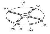
7 is a view showing a combination of the electrode plate group of the present invention and the positive electrode current collecting member and the negative electrode current collecting member.
8 (a) and 8 (b) are diagrams showing the state of welding of the current collector and the electrode plate of the present invention.
9A is an enlarged cross-sectional view of the region A given in FIG. 1B, and FIG. 9B is a cross-sectional view of the region B shown in FIG. .
Fig. 10 is an enlarged cross-sectional view of a region indicated by reference character C in Fig. 1 (b).
11 is a view showing a state in which the lithium-ion capacitor positive electrode plate unit of the present invention is housed in a container and sealed with a container lid.
12 is a view showing a modified example of the positive electrode current collector of the present invention.
13 is a view showing a modified example of the negative electrode current collector of the present invention.
이하, 도면을 참조하여, 본 발명을 원통 형상 리튬 이온 캐패시터에 적용한 실시 형태에 대하여 설명한다.Hereinafter, an embodiment in which the present invention is applied to a cylindrical lithium ion capacitor will be described with reference to the drawings.
(구성)(Configuration)
<전체 구성><Overall configuration>
도 1의 (a)는 정극을 위로 한 상태의 본 실시 형태의 리튬 이온 캐패시터(1)(이하, 캐패시터(1)라 약칭함)의 평면도이고, (b)는 도 1의 (a)의 IB-IB선 단면도이다. 또한 도 1의 (b)에는, 극판군(5)의 단면 형상은 도시를 생략하고 있고, 또한 단면 부분을 도시하는 빗금도 생략하고 있다. 캐패시터(1)는, 니켈 도금이 실시된 스틸제의 바닥이 있는 원통 형상의 용기(캔)(3)를 갖고 있다. 용기(3) 내에는, 극판군(5)과 정극 집전 부재(39) 및 부극 집전 부재(45)의 조합으로 이루어지는 리튬 이온 캐패시터용 극판군 유닛(2)이 수납되어 있다. 도 1의 (b) 및 도 2에 도시한 바와 같이, 극판군(5)은, 중공 원통형의 폴리프로필렌제 축심(7)에 띠 형상의 정극판(9) 및 부극판(11)이 제1 세퍼레이터(13) 및 제2 세퍼레이터(15)를 개재하여 권회되어 구성되어 있다. 도핑 전의 극판군(5) 내에는, 도 2에 도시한 바와 같이 금속 리튬을 포함하는 금속 리튬 지지 부재(17)가 배치되어 있다. 정극판(9)은, 2매의 분할 정극판(9A, 9B)으로 구성되어 있다. 제1 및 제2 세퍼레이터(13, 15)로서는, 크라프트지(kraft paper) 등의 다공질 기재를 사용할 수 있다.1 (a) is a plan view of a lithium ion capacitor 1 (hereinafter abbreviated as capacitor 1) of the present embodiment in a state where a positive electrode is up. Fig. 1 (b) -IB line section. In Fig. 1 (b), the cross-sectional shape of the
<정극판><Positive electrode plate>
정극판(9)을 구성하는 분할 정극판(9A, 9B)은, 길이 치수를 제외하고 동일한 구조를 갖고 있다. 도 3의 (a), (b)에 도시한 바와 같이, 분할 정극판(9A, 9B)은, 예를 들면 알루미늄박(정극 집전체)(19)의 양면에, 정극 활물질 합제(21)가 도착되어 구성되어 있다. 또한, 본원 명세서에 있어서, 알루미늄박은 알루미늄 합금박을 포함하는 것이다. 정극 활물질 합제(21)로서는, 예를 들면 활성탄과, 아크릴계 바인더로 이루어지는 결착제와, 카르복시메틸셀룰로오스(CMC)로 이루어지는 분산제의 혼합물을 사용할 수 있다. 알루미늄박(19)은, 다수의 관통 구멍이 형성되어 정극 활물질 합제가 도포되는 도포 시공부(23)와, 도포 시공부(23)의 길이 방향을 따라 형성되고 관통 구멍이 형성되어 있지 않은 미도포 시공부(25)를 갖고 있다. 도포 시공부(23)에 상기 도포 시공부의 폭 방향의 길이가 되지 않는 길이로 정극 활물질 합제(21)가 도착되어 있다. 즉, 정극 활물질 합제(21)의 도포층을 따라 알루미늄박의 미도포 시공부(25)가 노출된 상태로 남겨져 있다.The divided
<부극판><Negative plate>
부극판(11)도, 도 3의 (a), (b)에 도시한 분할 정극판(9A 및 9B)과 마찬가지의 구조를 갖고 있다. 즉, 부극판(11)은, 구리박(부극 집전체)(27)의 양면에 부극 활물질 합제(29)가 도착된 구조를 갖고 있다. 또한, 본원 명세서에 있어서, 구리박은, 순(純)구리박 뿐만 아니라 구리 합금박도 포함하는 것이다. 부극 활물질 합제(29)로서는, 예를 들면 리튬 이온을 흡장ㆍ방출 가능한 비정질 탄소와, 폴리불화비닐리덴(PVDF)으로 이루어지는 결착제와, 아세틸렌 블랙 등의 도전 조재의 혼합물을 사용할 수 있다. 구리박(27)은, 다수의 관통 구멍이 형성된 도포 시공부(31)와, 도포 시공부(31)의 길이 방향을 따라 형성되고 관통 구멍이 형성되어 있지 않은 미도포 시공부(33)를 갖고 있다. 도포 시공부(31)에는, 상기 도포 시공부(31)의 폭 방향의 길이가 되지 않는 길이로 부극 활물질 합제(29)가 도착되어 있다. 즉, 부극 활물질 합제(29)의 도포층을 따라 구리박의 미도포 시공부(33)가 노출된 상태로 남겨져 있다.The
<금속 리튬 지지 부재><Metal Lithium Supporting Member>
금속 리튬 지지 부재(17)는, 부극판(11)의 부극 활물질(본 예에서는 비정질 탄소)에 리튬 이온을 흡장(도프)시키기 위한 것이다. 도 4의 (a), (b)에 도시한 바와 같이, 금속 리튬 지지 부재(17)는, 박판 형상의 금속 리튬(35)과, 2매의 구리박(지지체)(37, 37)으로 구성되어 있다. 구리박(37, 37)은, 부극판(11)을 구성하는 구리박(27)과 동일한 것을 소정 치수로 절단하여 사용할 수 있다. 구리박(37, 37)에는, 다수의 관통 구멍이 형성되어 있고(도시하지 않음), 금속 리튬(35)은, 2매의 구리박(37)의 다수의 관통 구멍이 형성된 부분에 접촉하도록 하여 2매의 구리박(37, 37) 사이에 끼움 지지되어 있다.The metallic
<극판군><Plate group>
도 2에 도시하는 바와 같이, 극판군(5)은, 정극판(9)(분할 정극판(9A, 9B))과 부극판(11)이 직접 접촉하지 않도록, 2매의 세퍼레이터(13, 15)를 개재하여, 축심(7)을 중심으로 하여 단면 소용돌이 형상으로 권회되어 구성되어 있다. 그리고 극판군(5)의 직경 방향의 중앙 영역에는, 금속 리튬 지지 부재(17)의 권회층이 위치하도록 금속 리튬 지지 부재(17)가 부극판(11) 상에 배치되어 있다. 정극판(9)과 부극판(11)은, 각각의 미도포 시공부(미도포 시공부(25와 33))가 역방향으로 세퍼레이터(13, 15)보다도 외측으로 돌출되도록 배치되어 있다. 또한, 극판군(5)의 권회 종단부는, 풀림을 방지하기 위해, 점착 테이프를 권회 종단부와 극판군의 외주면에 걸쳐 부착함으로써 고정되어 있다.2, the
<정극 집전 부재>≪ Positive Electrode Collector Member &
정극 집전 부재(39)는, 알루미늄(알루미늄 합금을 포함함)으로 이루어지고, 도 5에 도시한 바와 같이, 중심 부분에 원형의 구멍(41)이 형성된 링 형상을 갖고 있다. 도 1의 (b)에 도시한 바와 같이, 구멍(41)은, 정극 집전 부재(39)가 극판군(5)의 중심으로부터 벗어나지 않도록 하기 위해, 축심(7)의 상단부에 끼워지는 직경을 갖고 있다. 정극 집전 부재(39)는, 극판군(5)에 포함되는 정극판(9)의 미도포 시공부(25)에 용접된다. 따라서 도 7에 도시한 바와 같이, 극판군(5)의 정극판(9)의 도포 시공부(25)가 위치하는 측의 상방으로부터 정극 집전 부재(39)를 극판군(5)을 향해 근접시켜, 정극판(9)의 알루미늄박(19)의 미도포 시공부(25) 상에 정극 집전 부재(39)를 얹는다. 그리고 후술하는 레이저 용접에 의해, 미도포 시공부(25)와 정극 집전 부재(39)를 용접한다. 레이저 용접으로 인해, 정극 집전 부재(39)에는, 극판군(5)과 접하는 방향을 향해 볼록해지고, 극판군(5)으로부터 이격되는 방향을 향해 개방되도록 용접용 오목부를 구성하는 홈(43)이 4개 형성되어 있다. 이들 홈(43)은, 프레스 가공에 의해 형성되어 있고, 정극 집전 부재(39)의 가상 중심점을 중심으로 하여, 방사상으로 직선적으로 연장되어 있다. 또한, 도 7에 있어서 정극 집전 부재(39)에 용접된 정극 단자부(44A)는, 도 1의 (b)에 도시한 용기 덮개(55)에 용접되는 것이다. 또한, 도 1의 (b)에 도시한 바와 같이, 조립시에는, 정극 집전 부재(39)의 외주연부에는, 용기(3)와 전기적으로 절연하기 위한 고무제의 절연 링 부재가 장착된다.The positive electrode
<부극 집전 부재>≪ Negative current collecting member &
부극 집전 부재(45)는, 니켈 또는 구리에 니켈 도금을 실시한 금속 재료 중 어느 하나로 형성되어 있다. 본 실시 형태에서는, 구리에 니켈 도금을 실시한 금속 재료로 부극 집전 부재(45)를 형성하였다. 도 6에 도시한 바와 같이, 부극 집전 부재(45)는, 중심 부분에 원형의 오목부(47)가 형성된 원반 형상을 갖고 있다. 오목부(47)는, 축심(7)의 하단부를 수납하도록 형성되어 있다. 도 7에 도시한 바와 같이, 부극 집전 부재(45)는, 극판군(5)의 부극판(11)의 구리박의 미도포 시공부(33)가 위치하는 측으로부터, 극판군(5)에 근접되어, 구리박(27)의 미도포 시공부(33) 상에 놓여 있다. 그리고 부극 집전 부재(45)와 구리박(27)의 미도포 시공부(33)는 레이저 용접된다. 부극 집전 부재(45)에도, 정극 집전 부재(39)와 마찬가지로, 극판군(5)을 향해 볼록해지고 극판군(5)으로부터 이격되는 방향을 향해 개방되도록 용접용 오목부를 구성하는 홈(49)이 4개 형성되어 있다. 이들 홈(49)은, 프레스 가공에 의해 형성되어 있고, 부극 집전 부재(45)의 가상 중심점을 중심으로 하여 방사상으로 직선적으로 연장되어 있다.The negative electrode current collecting
<극판군과 집전 부재의 용접><Welding of Electrode Plate and Current Collector Member>
극판군(5)의 미도포 시공부(25 및 33)와 집전 부재(정극 집전 부재(39) 및 부극 집전 부재(45))의 용접에는, 레이저 광을 사용한다. 특히, 본 실시 형태에서는, 레이저 용접 장치로서, 레이저 광을 연속적으로 발생하는 직접 집광형 반도체 레이저 장치(DLLㆍ도시하지 않음)를 사용하였다. 본 실시 형태의 직접 집광형 반도체 레이저 장치는, 고효율의 발진이 가능한 레이저 다이오드의 레이저 광을 사용하고 있고, YAG 레이저 광이나 CO2 레이저 광에 비해 집광도가 10분의 1 정도, 빔 형상이 타원형이고, 레이저 광에 의한 전도열로 금속을 녹이는 용접이 가능한 것이다. 이러한 직접 집광형 반도체 레이저 장치를 사용함으로써, 용접을 확실하게 하고, 또한 용융 금속의 비산에 의한 스패터가 적은 용접이 가능해진다. 부극 집전 부재(45)를 용접하는 경우를 예로 들어 설명하면, 레이저 광을 연속적으로 발생하는 직접 집광형 반도체 레이저 장치를 사용하여, 레이저 광을 부극 집전 부재(45)의 홈부(49)를 따라 부극 집전 부재(45)의 외주측으로부터 중심부를 향해 연속 조사하여 부극 집전 부재(45)를 국부적으로 용융하고, 용융 금속에 의해 부극판의 구리박의 미도포 시공부(33) 및 지지체(37)의 단부와 부극 집전 부재(45)를 용접한다. 본 실시 형태와 같이, 직접 집광형 반도체 레이저 장치를 사용하여 레이저 용접을 행하면, 부극 집전 부재를 효율적으로 용융시킬 수 있어, 확실하게 용접을 행하는 것이 가능해져, 용접부의 저항이 커지는 것을 확실하게 방지할 수 있다. 또한, 직접 집광형 반도체 레이저 장치 대신에, 파이버 도광형 반도체 레이저 장치를 사용해도 마찬가지로 양호한 용접 결과를 얻을 수 있다.A laser beam is used for welding the
도 8의 (a) 및 (b)는, 홈(43)과 직교하는 방향으로, 정극 집전 부재(39) 및 정극판(9)의 알루미늄박의 미도포 시공부(25)를 단면으로 하여 나타낸 용접 전의 단면도와 용접 후의 단면도이다. 도 8의 (a)에 도시한 용접을 행하기 전의 상태에서는, 정극 집전 부재(39)의 홈(43)을 형성하였기 때문에 형성된 산형의 볼록조의 선단부에 의해, 알루미늄박으로 이루어지는 정극 집전판이 변형되어 있다. 그리고 도 8의 (b)에 도시한 용접이 완료된 상태에서는, 정극 집전 부재(39)의 홈(43)의 저부의 부분이 용융되어, 용융 금속에 의해 정극판(9)의 알루미늄박의 미도포 시공부(25)와 정극 집전 부재(39)가 용접되어 있다.8 (a) and 8 (b) show a state in which the
부극 집전 부재(45)와 부극판(11)의 미도포 시공부(33)의 용접도 마찬가지로 행해진다. 즉, 부극 집전 부재(45)가 용융되어, 용융 금속에 의해 부극판(11)의 미도포 시공부(33)와 부극 집전 부재(45)가 용접된다. 또한, 후술하는 바와 같이, 부극 집전 부재(45)에는, 금속 리튬 지지 부재(17)를 구성하는 지지체(37, 37)의 단부도 마찬가지로 하여 용접되어 있다.Welding of the negative electrode current collecting
도 9의 (a)는 도 1에 부호 A를 부여한 영역을 확대하여 도시한 단면도이다. 도 9의 (a)는 축심(7) 부근에 용융 금속이 연장되도록, 정극 집전 부재(39)와 정극 미도포 시공부(25)가 용접되어 있는 모습을 도시하고 있다. 도 9의 (b)는, 도 1에 부호 B를 부여한 영역을 확대하여 도시하고 있다. 이 도면은, 용기(3)의 벽면 부근에 있어서, 정극 집전 부재(39)와 알루미늄박의 미도포 시공부(25)가 용접되어 있는 상태를 도시하고 있다. 양 도면에 있어서, 일부의 부재는 도시를 생략하고 있고, 또한 극판군의 층수는 실제의 것과는 다르게 도시되어 있다. 본 실시 형태에서는, 용기(3)측으로부터 중심을 향하는 방향으로 레이저 광을 이동시켜 용접을 행하고 있다. 그 결과, 도 9의 (b)에 도시한 바와 같이, 용융 금속(51)이 경화되어 형성되는 용접 비드는, 축심측으로 연장되도록 형성된다. 그로 인해 극판군(5)의 최외주면을 넘어 용기측을 향해 용융 금속(51)이 연장되는 일이 없다. 그 결과, 용기(3)의 벽면에 경화된 용융 금속(51)이 접촉하여, 단락이 발생하는 일은 없다.9 (a) is an enlarged cross-sectional view of a region to which the symbol A is assigned in Fig. 1. Fig. 9A shows a state in which the positive electrode current collecting
도 10은 도 1에 부호 C를 부여한 영역을 확대하여 도시한 단면도이다. 도 10은 부극 집전 부재(45)와 구리박의 미도포 시공부(33)가 용접되어 있는 모습을 도시하고 있다. 도 10에는, 축심(7)이나 용융 금속(53) 등의 일부의 부재에 대해서는 도시를 생략하고 있고, 또한 극판군의 층수도 실제와는 다르게 도시되어 있다. 도 10으로부터 명백한 바와 같이, 본 실시 형태에서는, 구리박의 미도포 시공부(33)뿐만 아니라, 금속 리튬 지지 부재(17)를 구성하는 지지체(37, 37)도 부극 집전 부재(45)에 용접되어 있다. 지지체(37, 37)의 단부의 세퍼레이터로부터의 돌출 길이는, 미도포 시공부(33)가 세퍼레이터(13, 15)로부터 돌출되는 길이보다도 길어지도록 지지체(37, 37)의 단부가 구성되어 있다. 이와 같이 구성함으로써, 부극 집전 부재(45)와 지지체(37, 37)의 용접이 보다 확실해져, 용접부의 저항값을 높이는 일 없이 금속 리튬(35)의 흡장을 확실하게 행할 수 있다. 또한, 지지체(37, 37)도 용접되어 있으므로, 금속 리튬(35)이 흡장된 후에, 잔존하는 지지체(37, 37)가 낙하하는 것을 방지할 수도 있다.Fig. 10 is an enlarged cross-sectional view of a region denoted by reference character C in Fig. 1. Fig. 10 shows a state in which the negative electrode current collecting
이와 같이, 본 실시 형태에서는, 1대의 직접 집광형 반도체 레이저 장치의 설정을 바꾸는 일 없이, 부극측 및 정극측의 용접 작업을 행할 수 있어, 생산 효율이 향상된다.As described above, in the present embodiment, it is possible to perform the welding work on the negative electrode side and the positive electrode side without changing the setting of one direct-light-converging type semiconductor laser device, and the production efficiency is improved.
<극판군의 용기에의 수납>≪ Storage in the container of the plate group >
도 11에 도시한 바와 같이, 집전 부재를 용접한 극판군(5), 즉, 리튬 이온 캐패시터용 극판군 유닛(2)은, 용기(3)에 수납된다. 리튬 이온 캐패시터용 극판군 유닛(2)을 수납한 상태에서, 부극 집전 부재(45)의 오목부(47)와, 용기의 저부는 스폿 용접에 의해 용접되고, 전기적으로 접속되어 있다.As shown in Fig. 11, the
정극 집전 부재(39)의 외주연부에는, 정극 집전 부재와 용기(3)를 전기적으로 절연하기 위한 절연 링 부재(63)가 장착되어 있다. 용기(3)에는, 개구부 근방에 있어서, 교축 가공이 실시되고, 도 1의 (b)에 도시한 바와 같이, 리튬 이온 캐패시터용 극판군 유닛(2)은 용기(3) 내에서 고정된다.An insulating
정극 집전 부재(39)의 상방에는, 정극 단자를 구성하는 용기 덮개(55)가 배치된다. 용기 덮개(55)는, 정극 집전 부재(39) 상에 배치된 덮개 본체(57)와, 이 덮개 본체(57)와 조합되는 덮개 캡(59)으로 구성되어 있다. 덮개 본체(57)는, 알루미늄에 의해 형성되어 있고, 덮개 캡(59)은, 용기(8)와 마찬가지로 니켈 도금이 실시된 스틸에 의해 형성되어 있다. 덮개 캡(59)은, 환 형상의 평탄부(59a)와, 평탄부(59a)의 중앙부로부터 돌출되는 볼록부(59b)를 갖고 있다. 용기 덮개(55)는, 덮개 캡(59)의 평탄부(59a)의 외주부가 덮개 본체(57)의 테두리부에 컬링 가공이 실시되어(코킹되어) 구성되어 있다. 덮개 캡(59)의 볼록부(59b)와 덮개 본체(57)의 사이에는, 공극부(61)가 형성되어 있다.Above the positive
정극 집전 부재(39)의 상면에는, 리본 형상의 알루미늄박을 적층한 2개의 정극 단자부 중 1개의 정극 단자부(44A)의 일단부가 접합되어 있다. 정극 단자부의 다른 1개의 정극 단자부(44B)는, 용기 덮개(55)를 구성하는 덮개 본체(57)의 외저면에 용접되어 있다. 또한, 2개의 정극 단자부(44A, 44B)의 타단부끼리도 접합된다. 이에 의해, 덮개 본체(57)는 극판군(5)의 한쪽의 극판(정극판(9))과 전기적으로 접속된다.One end of one positive
상술한 바와 같이, 교축 가공이 실시된 용기에는, 원환상의 단차부(3a)가 형성되어 있고, 용기 덮개(55)는, 그 위에 용기 덮개(55)와 용기(3)를 전기적으로 절연하기 위한 절연 부재(65)를 개재하여 배치된다. 그리고 개구 단부(3b)는, 용기 덮개(55)에 근접하도록 컬링 가공(코킹 가공)되어 있다. 그 결과, 컬링 가공된 개구 단부(3b)와 단차부(3a)의 사이에, 용기 덮개(55)가 절연 부재(65)를 개재하여 끼워진 상태로 고정된다. 이에 의해, 캐패시터(1)의 내부는 밀봉된다.As described above, the container in which the throttle processing is performed is formed with the stepped
용기(3) 내에는, 리튬 이온 캐패시터용 극판군 유닛(2) 전체를 침윤 가능한 양의 비수 전해액(도시하지 않음)이 주액되어 있다. 비수 전해액에는, 예를 들면 에틸렌카보네이트(EC)와 디메틸카보네이트(DMC)와 디에틸카보네이트(DEC)를 체적비 30:50:20의 비율로 혼합한 용매 중에 리튬염으로서 6불화인산리튬(LiPF6)을 용해한 용액을 사용할 수 있다.In the
(집전 부재의 변형예)(Variation of current collector member)
도 12 및 도 13은 집전 부재의 변형예를 도시하고 있다. 도 12 및 도 13에는, 도 5 및 도 6에 도시한 실시 형태와 동일한 부재에, 도 5 및 도 6에 부여한 부호의 수에 100의 수를 더한 수의 번호를 부여하고 설명을 생략한다. 도 12의 집전 부재에서는, 홈(143)을 정극 집전 부재(139)의 직경보다도 짧게 형성하고, 정극 집전 부재(139)의 외주부에는, 홈(143)의 연장선상에 갈고리부(165)가 형성되어 있다. 이 갈고리부(165)에 의해, 극판군(105)이 직경 방향으로 이동하는 것이 저지된다. 또한 레이저 용접시에, 용융 금속이 극판군의 최외층을 넘어 직경 방향 외측으로 연장되게 되는 것을 방지할 수 있다. 부극 집전 부재(145)의 갈고리부(167)도 마찬가지의 효과가 있다.12 and 13 show a modification of the current collector. In Figs. 12 and 13, the same reference numerals as in Figs. 5 and 6 denote the same reference numerals as in Figs. 5 and 6 plus 100, and the description thereof is omitted. 12, the
본 발명에 따르면, 집전 부재(정극 집전 부재 및 부극 집전 부재)와, 극판(정극판 및 부극판)이 확실하게 용접되어, 용접부의 저항이 낮은 캐패시터용 극판군 유닛을 얻을 수 있고, 또한 접촉 저항이 낮은 리튬 이온 캐패시터를 얻을 수 있다.According to the present invention, it is possible to obtain a capacitor-use electrode plate group unit in which the current collecting members (the positive electrode current collecting member and the negative electrode current collecting member) and the electrode plates (positive electrode plate and negative electrode plate) are reliably welded, This low lithium ion capacitor can be obtained.
1 : 리튬 이온 캐패시터
2 : 리튬 이온 캐패시터용 극판군 유닛
3 : 용기
5 : 극판군
7 : 축심
9 : 정극판
11 : 부극판
13 : 제1 세퍼레이터
15 : 제2 세퍼레이터
17 : 금속 리튬 지지 부재
19 : 알루미늄박(정극 집전체)
21 : 정극 활물질 합제
23 : 도포 시공부
25 : 미도포 시공부
27 : 구리박(부극 집전체)
29 : 부극 활물질 합제
31 : 도포 시공부
33 : 미도포 시공부
35 : 금속 리튬
37 : 구리박(지지체)
39 : 정극 집전 부재
41 : 구멍
43 : 홈
44 : 정극 단자부
45 : 부극 집전 부재
47 : 오목부
49 : 홈
51, 53 : 용융 금속
55 : 용기 덮개
57 : 덮개 본체
59 : 덮개 캡
61 : 공극부
63 : 절연 링 부재1: Lithium ion capacitor
2: Plate group unit for lithium ion capacitor
3: container
5: Polar plate group
7: Shaft
9: Positive plate
11: negative plate
13: first separator
15: Second separator
17: metal lithium supporting member
19: Aluminum foil (positive electrode collector)
21: Positive electrode active material mixture
23:
25: Unapplied construction part
27: Copper foil (negative electrode collector)
29: Negative electrode active material mixture
31:
33: Uncoated application part
35: metal lithium
37: Copper foil (support)
39: positive current collector member
41: hole
43: Home
44: Positive electrode terminal portion
45: negative electrode current collector member
47:
49: Home
51, 53: molten metal
55: Container cover
57:
59: Cover cap
61:
63: Insulation ring member
Claims (11)
Translated fromKorean상기 정극판의 상기 알루미늄박에 전기적으로 접속된 알루미늄으로 이루어지는 정극 집전 부재와,
상기 부극판의 상기 구리박에 전기적으로 접속된 금속 재료로 이루어지는 부극 집전 부재와,
금속 리튬과, 상기 부극 집전 부재와 전기적으로 접속되어 이온 투과성을 갖고 또한 상기 금속 리튬을 보유 지지하는 구조를 갖는 구리박으로 이루어지는 지지체를 구비한 금속 리튬 지지 부재를 갖고,
상기 금속 리튬이 상기 부극판의 상기 부극 활물질 합제 중의 부극 활물질에 흡장됨으로써 상기 구리박만이 잔존하도록 상기 금속 리튬 지지 부재가, 상기 극판군 내 또는 상기 극판군에 인접하여 상기 정극판과 전기적으로 절연된 상태에서 배치되어 이루어지는 리튬 이온 캐패시터용 극판군 유닛의 제조 방법으로서,
상기 부극판으로서, 상기 부극 활물질 합제의 도포층을 따라 상기 구리박의 미도포 시공부가 남겨진 것을 준비하고,
상기 정극판으로서, 상기 정극 활물질 합제의 도포층을 따라 상기 알루미늄박의 미도포 시공부가 남겨진 것을 준비하고,
상기 극판군을, 상기 부극판의 상기 미도포 시공부와 상기 정극판의 상기 미도포 시공부가 각각 역방향으로 상기 세퍼레이터보다 외측으로 돌출되도록 구성하고,
상기 지지체의 단부의 상기 세퍼레이터로부터의 돌출 길이를, 상기 부극판의 상기 미도포 시공부의 상기 세퍼레이터로부터의 돌출 길이보다도 길어지도록 상기 극판군을 구성하고,
상기 금속 리튬 지지 부재는, 상기 금속 리튬 지지 부재의 권회층이, 상기 극판군의 직경 방향의 중앙 영역에 위치하도록 배치되어 있고,
상기 극판군의 상기 부극판의 상기 미도포 시공부 및 상기 지지체의 단부 상에 상기 부극 집전 부재를 얹은 상태에서, 레이저 광을 연속적으로 발생하는 직접 집광형 반도체 레이저 장치를 사용하여, 상기 레이저 광을 상기 부극 집전 부재에 연속 조사하여 상기 부극 집전 부재를 국부적으로 용융하고, 용융 금속에 의해 상기 부극판의 상기 미도포 시공부 및 상기 지지체의 단부와 상기 부극 집전 부재를 용접하고,
상기 극판군의 상기 정극판의 상기 미도포 시공부 상에 상기 정극 집전 부재를 얹은 상태에서, 레이저 광을 연속적으로 발생하는 직접 집광형 반도체 레이저 장치를 사용하여, 상기 레이저 광을 상기 정극 집전 부재에 연속 조사하여 상기 정극 집전 부재를 국부적으로 용융하고, 용융 금속에 의해 상기 정극판의 상기 미도포 시공부와 상기 정극 집전 부재를 용접하는 것을 특징으로 하는 리튬 이온 캐패시터용 극판군 유닛의 제조 방법.An electrode plate group in which a positive electrode plate having a positive electrode active material mixture arrived at an aluminum foil and a negative electrode plate having a negative electrode active material mixture arrived in a copper foil are stacked with a separator interposed therebetween,
A positive electrode current collector made of aluminum electrically connected to the aluminum foil of the positive electrode plate,
A negative electrode current collector made of a metallic material electrically connected to the copper foil of the negative electrode plate;
1. A lithium secondary battery comprising: a metallic lithium supporting member having metallic lithium and a support made of a copper foil having a structure that is electrically connected to the negative electrode current collecting member and has ion permeability and retains the metallic lithium,
The metallic lithium is stored in the negative electrode active material in the negative electrode active material mixture of the negative electrode plate so that only the copper foil remains so that the metallic lithium support member is electrically insulated from the positive electrode plate in the electrode plate group or adjacent to the electrode plate group A method of manufacturing a lithium ion capacitor unit for a lithium ion capacitor,
As the negative electrode plate, an uncoated portion of the copper foil is left along the coating layer of the negative electrode active material mixture,
As the positive electrode plate, an uncoated portion of the aluminum foil was left along the coating layer of the positive electrode active material mixture,
Wherein the electrode plate group is configured such that the uncoated portions of the negative electrode plate and the uncoated portions of the positive electrode plate project outwardly from the separator in opposite directions,
The electrode plate group is configured so that the protruding length of the end portion of the support from the separator is longer than the protruding length of the uncoated portion of the negative electrode plate from the separator,
Wherein the metal lithium supporting member is arranged so that the winding layer of the metal lithium supporting member is located in the central region in the radial direction of the electrode plate group,
A direct condensing type semiconductor laser device which continuously generates laser light in a state in which the negative electrode current collecting member is placed on the uncoated portion of the negative electrode plate of the electrode plate group and the end portion of the support, The negative electrode current collecting member is locally melted by continuous irradiation to the negative electrode current collecting member and the uncoated portion of the negative electrode plate and the end portion of the supporting member and the negative electrode current collecting member are welded with molten metal,
A direct-condensing type semiconductor laser device for continuously generating laser light in a state in which the positive electrode current collecting member is placed on the uncoated portion of the positive electrode plate of the electrode plate group and the laser light is applied to the positive electrode collector Wherein the positive electrode current collecting member is locally melted by continuous irradiation and the uncoated portion of the positive electrode plate is welded to the positive electrode collector member by a molten metal.
상기 정극판의 상기 알루미늄박에 전기적으로 접속된 알루미늄으로 이루어지는 정극 집전 부재와,
상기 부극판의 상기 구리박에 전기적으로 접속된 금속 재료로 이루어지는 부극 집전 부재와,
금속 리튬과, 상기 부극 집전 부재와 전기적으로 접속되어 이온 투과성을 갖고 또한 상기 금속 리튬을 보유 지지하는 구조를 갖는 구리박으로 이루어지는 지지체를 구비한 금속 리튬 지지 부재를 갖고,
상기 금속 리튬이 상기 부극판의 상기 부극 활물질 합제 중의 부극 활물질에 흡장됨으로써 상기 구리박만이 잔존하도록 상기 금속 리튬 지지 부재가, 상기 극판군 내 또는 상기 극판군에 인접하여 상기 정극판과 전기적으로 절연된 상태에서 배치되어 이루어지는 리튬 이온 캐패시터용 극판군 유닛의 제조 방법으로서,
상기 부극판으로서, 상기 부극 활물질 합제의 도포층을 따라 상기 구리박의 미도포 시공부가 남겨진 것을 준비하고,
상기 정극판으로서, 상기 정극 활물질 합제의 도포층을 따라 상기 알루미늄박의 미도포 시공부가 남겨진 것을 준비하고,
상기 극판군을, 상기 부극판의 상기 미도포 시공부와 상기 정극판의 상기 미도포 시공부가 각각 역방향으로 상기 세퍼레이터보다 외측으로 돌출되도록 구성하고,
상기 극판군의 상기 부극판의 상기 미도포 시공부 및 상기 지지체의 단부 상에 상기 부극 집전 부재를 얹은 상태에서, 레이저 광을 연속적으로 발생하는 직접 집광형 반도체 레이저 장치를 사용하여, 상기 레이저 광을 상기 부극 집전 부재에 연속 조사하여 상기 부극 집전 부재를 국부적으로 용융하고, 용융 금속에 의해 상기 부극판의 상기 미도포 시공부 및 상기 지지체의 단부와 상기 부극 집전 부재를 용접하는 것을 특징으로 하는 리튬 이온 캐패시터용 극판군 유닛의 제조 방법.An electrode plate group in which a positive electrode plate having a positive electrode active material mixture arrived at an aluminum foil and a negative electrode plate having a negative electrode active material mixture arrived in a copper foil are stacked with a separator interposed therebetween,
A positive electrode current collector made of aluminum electrically connected to the aluminum foil of the positive electrode plate,
A negative electrode current collector made of a metallic material electrically connected to the copper foil of the negative electrode plate;
1. A lithium secondary battery comprising: a metallic lithium supporting member having metallic lithium and a support made of a copper foil having a structure that is electrically connected to the negative electrode current collecting member and has ion permeability and retains the metallic lithium,
The metallic lithium is stored in the negative electrode active material in the negative electrode active material mixture of the negative electrode plate so that only the copper foil remains so that the metallic lithium support member is electrically insulated from the positive electrode plate in the electrode plate group or adjacent to the electrode plate group A method of manufacturing a lithium ion capacitor unit for a lithium ion capacitor,
As the negative electrode plate, an uncoated portion of the copper foil is left along the coating layer of the negative electrode active material mixture,
As the positive electrode plate, an uncoated portion of the aluminum foil was left along the coating layer of the positive electrode active material mixture,
Wherein the electrode plate group is configured such that the uncoated portions of the negative electrode plate and the uncoated portions of the positive electrode plate project outwardly from the separator in opposite directions,
A direct condensing type semiconductor laser device which continuously generates laser light in a state in which the negative electrode current collecting member is placed on the uncoated portion of the negative electrode plate of the electrode plate group and the end portion of the support, Wherein the negative electrode current collector is continuously irradiated with the negative electrode current collector to melt locally the molten metal to weld the uncoated portion of the negative electrode and the end portion of the support to the negative electrode current collector. A method of manufacturing a capacitor plate unit.
상기 극판군의 상기 정극판의 상기 미도포 시공부 상에 상기 정극 집전 부재를 얹은 상태에서, 레이저 광을 연속적으로 발생하는 직접 집광형 반도체 레이저 장치를 사용하여, 상기 레이저 광을 상기 정극 집전 부재에 연속 조사하여 상기 정극 집전 부재를 국부적으로 용융하고, 용융 금속에 의해 상기 정극판의 상기 미도포 시공부와 상기 정극 집전 부재를 용접하는 리튬 이온 캐패시터용 극판군 유닛의 제조 방법.3. The method of claim 2,
A direct-condensing type semiconductor laser device for continuously generating laser light in a state in which the positive electrode current collecting member is placed on the uncoated portion of the positive electrode plate of the electrode plate group and the laser light is applied to the positive electrode collector Wherein the positive electrode current collecting member is locally melted by continuous irradiation to weld the uncoated portion of the positive electrode plate and the positive electrode collector member by molten metal to the positive electrode collector member.
상기 용융 금속이 상기 극판군의 가장 직경 방향 외측에 위치하는 극판층을 넘어 직경 방향 외측으로 연장되지 않도록 용접을 행하는 리튬 이온 캐패시터용 극판군 유닛의 제조 방법.3. The method according to claim 1 or 2,
Wherein the molten metal is welded so that the molten metal does not extend radially outward beyond the electrode plate layer located at the outermost radial direction of the electrode plate group.
상기 지지체의 단부의 상기 세퍼레이터로부터의 돌출 길이를, 상기 부극판의 상기 미도포 시공부의 상기 세퍼레이터로부터의 돌출 길이보다도 길어지도록 상기 극판군을 구성하는 것을 특징으로 하는 리튬 이온 캐패시터용 극판군 유닛의 제조 방법.3. The method of claim 2,
Wherein the electrode plate group is constructed so that the protruding length of the end portion of the support from the separator is longer than the protruding length of the uncoated portion of the negative electrode plate from the separator. Way.
상기 금속 리튬 지지 부재는, 상기 금속 리튬 지지 부재의 권회층이, 상기 극판군의 직경 방향의 중앙 영역에 위치하도록 배치되어 있는 것을 특징으로 하는 리튬 이온 캐패시터용 극판군 유닛의 제조 방법.3. The method of claim 2,
Wherein the metal lithium support member is disposed such that the winding layers of the metal lithium supporting members are located in the radial center region of the electrode plate group.
상기 부극 집전 부재 및 상기 정극 집전 부재에는, 상기 레이저 광이 조사되는 부분에 직선적으로 연장되는 오목부 또는 볼록부가 프레스 가공되어 있는 리튬 이온 캐패시터용 극판군 유닛의 제조 방법.3. The method according to claim 1 or 2,
Wherein the negative electrode current collecting member and the positive electrode current collecting member are formed with a depressed portion or a convex portion linearly extending to a portion irradiated with the laser beam.
상기 금속 재료는, 니켈 또는 구리에 니켈 도금이 실시된 것인 리튬 이온 캐패시터용 극판군 유닛의 제조 방법.3. The method according to claim 1 or 2,
Wherein the metallic material is nickel or copper plated with nickel.
상기 정극판의 상기 알루미늄박에 전기적으로 접속된 알루미늄으로 이루어지는 정극 집전 부재와,
상기 부극판의 상기 구리박에 전기적으로 접속된 금속 재료로 이루어지는 부극 집전 부재와,
금속 리튬과, 상기 부극 집전 부재와 전기적으로 접속되어 이온 투과성을 갖고 또한 상기 금속 리튬을 보유 지지하는 구조를 갖는 구리박으로 이루어지는 지지체를 구비한 금속 리튬 지지 부재를 갖고,
상기 금속 리튬이 상기 부극판의 상기 부극 활물질 합제 중의 부극 활물질에 흡장됨으로써 상기 구리박만이 잔존하도록 상기 금속 리튬 지지 부재가, 상기 극판군 내 또는 상기 극판군에 인접하여 상기 정극판과 전기적으로 절연된 상태에서 배치되어 이루어지는 리튬 이온 캐패시터용 극판군 유닛이 바닥이 있는 용기 내에 수납되고, 상기 용기의 개구부가 단자 전극을 겸하는 덮개 부재에 의해 밀봉되어 있는 리튬 이온 캐패시터로서,
상기 부극판은 상기 부극 활물질 합제의 도포층을 따라 상기 구리박의 미도포 시공부가 남겨진 것이고, 또한 상기 정극판은 상기 정극 활물질 합제의 도포층을 따라 상기 알루미늄박의 미도포 시공부가 남겨진 것이고,
상기 극판군이, 상기 부극판의 상기 미도포 시공부와 상기 정극판의 상기 미도포 시공부가 각각 역방향으로 상기 세퍼레이터보다 외측으로 돌출되도록 구성되고,
상기 극판군의 상기 부극판의 상기 미도포 시공부 및 상기 지지체의 단부에 상기 부극 집전 부재가 레이저 광을 연속적으로 발생시키는 직접 집광형 반도체 레이저 장치를 이용하여 레이저 용접되어 있고,
상기 부극 집전 부재의 상기 금속 재료는, 니켈 또는 구리에 니켈 도금이 실시된 것을 특징으로 하는 리튬 이온 캐패시터.An electrode plate group in which a positive electrode plate having a positive electrode active material mixture arrived at an aluminum foil and a negative electrode plate having a negative electrode active material mixture arrived in a copper foil are stacked with a separator interposed therebetween,
A positive electrode current collector made of aluminum electrically connected to the aluminum foil of the positive electrode plate,
A negative electrode current collector made of a metallic material electrically connected to the copper foil of the negative electrode plate;
1. A lithium secondary battery comprising: a metallic lithium supporting member having metallic lithium and a support made of a copper foil having a structure that is electrically connected to the negative electrode current collecting member and has ion permeability and retains the metallic lithium,
The metallic lithium is stored in the negative electrode active material in the negative electrode active material mixture of the negative electrode plate so that only the copper foil remains so that the metallic lithium support member is electrically insulated from the positive electrode plate in the electrode plate group or adjacent to the electrode plate group Wherein the lithium ion capacitor unit for lithium ion capacitor is housed in a container having a bottom and the opening of the container is sealed by a lid member that doubles as a terminal electrode,
Wherein the negative electrode plate is left uncoated portions of the copper foil along the coating layer of the negative electrode active material mixture and the positive electrode plate is left uncoated portions of the aluminum foil along the coating layer of the positive electrode active material mixture,
Wherein the electrode plate group is configured such that the uncoated portions of the negative electrode plate and the uncoated portions of the positive electrode plate project outwardly from the separator in opposite directions,
Wherein the negative electrode current collecting member is laser-welded to the uncoated portion of the negative electrode plate of the electrode plate group and the end portion of the support using a direct light-converging type semiconductor laser device that continuously generates laser light,
Wherein the metallic material of the negative electrode current collecting member is nickel or copper plated with nickel.
Applications Claiming Priority (3)
| Application Number | Priority Date | Filing Date | Title |
|---|---|---|---|
| JPJP-P-2010-207993 | 2010-09-16 | ||
| JP2010207993 | 2010-09-16 | ||
| PCT/JP2011/071159WO2012036249A1 (en) | 2010-09-16 | 2011-09-15 | Method for producing electrode plate group unit for lithium-ion capacitor, and lithium-ion capacitor |
Publications (2)
| Publication Number | Publication Date |
|---|---|
| KR20130108099A KR20130108099A (en) | 2013-10-02 |
| KR101851572B1true KR101851572B1 (en) | 2018-04-26 |
Family
ID=45831705
Family Applications (1)
| Application Number | Title | Priority Date | Filing Date |
|---|---|---|---|
| KR1020127033725AExpired - Fee RelatedKR101851572B1 (en) | 2010-09-16 | 2011-09-15 | Method for producing electrode plate group unit for lithium-ion capacitor, and lithium-ion capacitor |
Country Status (6)
| Country | Link |
|---|---|
| US (1) | US9159496B2 (en) |
| EP (1) | EP2618350A4 (en) |
| JP (1) | JP5966924B2 (en) |
| KR (1) | KR101851572B1 (en) |
| CN (1) | CN102959662B (en) |
| WO (1) | WO2012036249A1 (en) |
Families Citing this family (16)
| Publication number | Priority date | Publication date | Assignee | Title |
|---|---|---|---|---|
| JP2013207026A (en)* | 2012-03-28 | 2013-10-07 | Panasonic Corp | Capacitor and capacitor module using the same |
| US9911543B2 (en) | 2013-12-26 | 2018-03-06 | Hitachi Chemical Company, Ltd. | Capacitor |
| JP6390624B2 (en)* | 2013-12-26 | 2018-09-19 | 日立化成株式会社 | Power storage device |
| JP6201795B2 (en)* | 2014-02-10 | 2017-09-27 | トヨタ自動車株式会社 | Method for manufacturing power storage device |
| CN104008893B (en)* | 2014-04-11 | 2016-10-19 | 中国科学院电工研究所 | Preparation method of lithium-ion hybrid capacitor and lithium-ion hybrid capacitor |
| KR102177485B1 (en)* | 2015-01-14 | 2020-11-11 | 엘에스엠트론 주식회사 | Electric energy storage device improved in inner terminal combination structure |
| US10692662B2 (en) | 2016-01-07 | 2020-06-23 | Nesscap Co., Ltd. | Electric double layer device |
| JP6262402B2 (en)* | 2016-01-22 | 2018-01-17 | 旭化成株式会社 | Non-aqueous lithium storage element |
| CN106997809B (en)* | 2016-01-25 | 2018-12-04 | 奈斯卡普股份有限公司 | Electric double layer device |
| CN107221451A (en)* | 2017-04-26 | 2017-09-29 | 烯晶碳能电子科技无锡有限公司 | A kind of Large Copacity electrochemical device monomer structure and its assemble method |
| CN107731541B (en)* | 2017-09-13 | 2019-04-19 | 东莞凯德新能源有限公司 | Cylindrical high-power lithium ion capacitor and preparation method thereof |
| US10944096B2 (en)* | 2018-04-10 | 2021-03-09 | GM Global Technology Operations LLC | Method of manufacturing a lithium metal negative electrode |
| US12154719B2 (en) | 2018-11-30 | 2024-11-26 | Panasonic Intellectual Property Management Co., Ltd. | Electrochemical device negative electrode and electrochemical device, and method for manufacturing electrochemical device negative electrode and method for manufacturing electrochemical device |
| WO2021193838A1 (en) | 2020-03-26 | 2021-09-30 | パナソニックIpマネジメント株式会社 | Negative electrode for electrochemical device, and electrochemical device |
| CN115693041A (en)* | 2021-07-23 | 2023-02-03 | 比亚迪股份有限公司 | Cylindrical battery |
| EP4507077A1 (en)* | 2023-08-08 | 2025-02-12 | VARTA Microbattery GmbH | Energy storage element and method of manufacture |
Citations (2)
| Publication number | Priority date | Publication date | Assignee | Title |
|---|---|---|---|---|
| JP2010093178A (en) | 2008-10-10 | 2010-04-22 | Panasonic Corp | Electrochemical capacitance and method of manufacturing the same |
| JP2010186779A (en)* | 2009-02-10 | 2010-08-26 | Shin Kobe Electric Mach Co Ltd | Lithium ion capacitor |
Family Cites Families (9)
| Publication number | Priority date | Publication date | Assignee | Title |
|---|---|---|---|---|
| JP4866496B2 (en)* | 1999-04-08 | 2012-02-01 | パナソニック株式会社 | Manufacturing method of secondary battery |
| JP2006224129A (en)* | 2005-02-16 | 2006-08-31 | Tokyu Car Corp | Laser welded structure and laser welding method |
| JP2006286974A (en) | 2005-03-31 | 2006-10-19 | Nippon Chemicon Corp | Capacitor and its manufacturing process |
| JP2007229773A (en)* | 2006-03-02 | 2007-09-13 | Toyota Auto Body Co Ltd | Laser welding method and laser welding apparatus |
| JP4444989B2 (en)* | 2007-06-11 | 2010-03-31 | 日立ビークルエナジー株式会社 | Lithium ion secondary battery |
| WO2010041461A1 (en)* | 2008-10-10 | 2010-04-15 | パナソニック株式会社 | Electric condenser, unit equipped with electric condenser, and method of manufacturing electric condenser |
| JP5295745B2 (en) | 2008-12-15 | 2013-09-18 | 新神戸電機株式会社 | Laminated body and lithium ion capacitor |
| JP5317687B2 (en)* | 2008-12-26 | 2013-10-16 | Jmエナジー株式会社 | Winding type power storage |
| JP2010283115A (en) | 2009-06-04 | 2010-12-16 | Panasonic Corp | Manufacturing method of energy device |
- 2011
- 2011-09-15EPEP11825249.3Apatent/EP2618350A4/ennot_activeWithdrawn
- 2011-09-15KRKR1020127033725Apatent/KR101851572B1/ennot_activeExpired - Fee Related
- 2011-09-15CNCN201180031690.1Apatent/CN102959662B/ennot_activeExpired - Fee Related
- 2011-09-15USUS13/805,256patent/US9159496B2/ennot_activeExpired - Fee Related
- 2011-09-15WOPCT/JP2011/071159patent/WO2012036249A1/enactiveApplication Filing
- 2011-09-15JPJP2012518628Apatent/JP5966924B2/ennot_activeExpired - Fee Related
Patent Citations (2)
| Publication number | Priority date | Publication date | Assignee | Title |
|---|---|---|---|---|
| JP2010093178A (en) | 2008-10-10 | 2010-04-22 | Panasonic Corp | Electrochemical capacitance and method of manufacturing the same |
| JP2010186779A (en)* | 2009-02-10 | 2010-08-26 | Shin Kobe Electric Mach Co Ltd | Lithium ion capacitor |
Also Published As
| Publication number | Publication date |
|---|---|
| US20130163147A1 (en) | 2013-06-27 |
| JPWO2012036249A1 (en) | 2014-02-03 |
| KR20130108099A (en) | 2013-10-02 |
| JP5966924B2 (en) | 2016-08-10 |
| CN102959662B (en) | 2016-04-27 |
| US9159496B2 (en) | 2015-10-13 |
| CN102959662A (en) | 2013-03-06 |
| WO2012036249A1 (en) | 2012-03-22 |
| EP2618350A4 (en) | 2018-03-14 |
| EP2618350A1 (en) | 2013-07-24 |
Similar Documents
| Publication | Publication Date | Title |
|---|---|---|
| KR101851572B1 (en) | Method for producing electrode plate group unit for lithium-ion capacitor, and lithium-ion capacitor | |
| US8568916B2 (en) | Lithium ion secondary battery | |
| JP4444989B2 (en) | Lithium ion secondary battery | |
| JP6331079B2 (en) | Laser welding method and laser welding apparatus | |
| WO2015146077A1 (en) | Cylindrical hermetically sealed battery | |
| US20100316897A1 (en) | Secondary battery | |
| JP2009032640A (en) | Sealed battery and its manufacturing method | |
| JP5137516B2 (en) | Sealed battery | |
| JP7320165B2 (en) | secondary battery | |
| JP3831595B2 (en) | Cylindrical secondary battery | |
| JP2010080081A (en) | Secondary battery | |
| JP5384071B2 (en) | Sealed battery | |
| WO2009153914A1 (en) | Battery and method for manufacturing same | |
| JP7394051B2 (en) | Battery and its manufacturing method | |
| JP2012185912A (en) | Cylindrical secondary cell | |
| JP5064699B2 (en) | Cylindrical battery and manufacturing method thereof | |
| JP5248210B2 (en) | Lithium ion secondary battery | |
| JP2016091670A (en) | Cylindrical secondary battery | |
| JP2024536378A (en) | Energy storage element and manufacturing process | |
| JP4428965B2 (en) | Battery unit | |
| WO2025142919A1 (en) | Power storage device | |
| JP2004253252A (en) | Lithium secondary battery | |
| JP2015153455A (en) | Power storage device and manufacturing method thereof | |
| WO2016125770A1 (en) | Electrolyte for lithium ion capacitor and lithium ion capacitor |
Legal Events
| Date | Code | Title | Description |
|---|---|---|---|
| PA0105 | International application | St.27 status event code:A-0-1-A10-A15-nap-PA0105 | |
| PG1501 | Laying open of application | St.27 status event code:A-1-1-Q10-Q12-nap-PG1501 | |
| PA0201 | Request for examination | St.27 status event code:A-1-2-D10-D11-exm-PA0201 | |
| D13-X000 | Search requested | St.27 status event code:A-1-2-D10-D13-srh-X000 | |
| D14-X000 | Search report completed | St.27 status event code:A-1-2-D10-D14-srh-X000 | |
| E902 | Notification of reason for refusal | ||
| PE0902 | Notice of grounds for rejection | St.27 status event code:A-1-2-D10-D21-exm-PE0902 | |
| E13-X000 | Pre-grant limitation requested | St.27 status event code:A-2-3-E10-E13-lim-X000 | |
| P11-X000 | Amendment of application requested | St.27 status event code:A-2-2-P10-P11-nap-X000 | |
| P13-X000 | Application amended | St.27 status event code:A-2-2-P10-P13-nap-X000 | |
| E701 | Decision to grant or registration of patent right | ||
| PE0701 | Decision of registration | St.27 status event code:A-1-2-D10-D22-exm-PE0701 | |
| N231 | Notification of change of applicant | ||
| PN2301 | Change of applicant | St.27 status event code:A-3-3-R10-R13-asn-PN2301 St.27 status event code:A-3-3-R10-R11-asn-PN2301 | |
| GRNT | Written decision to grant | ||
| PR0701 | Registration of establishment | St.27 status event code:A-2-4-F10-F11-exm-PR0701 | |
| PR1002 | Payment of registration fee | St.27 status event code:A-2-2-U10-U12-oth-PR1002 Fee payment year number:1 | |
| PG1601 | Publication of registration | St.27 status event code:A-4-4-Q10-Q13-nap-PG1601 | |
| R18-X000 | Changes to party contact information recorded | St.27 status event code:A-5-5-R10-R18-oth-X000 | |
| PN2301 | Change of applicant | St.27 status event code:A-5-5-R10-R13-asn-PN2301 St.27 status event code:A-5-5-R10-R11-asn-PN2301 | |
| PR1001 | Payment of annual fee | St.27 status event code:A-4-4-U10-U11-oth-PR1001 Fee payment year number:4 | |
| PC1903 | Unpaid annual fee | St.27 status event code:A-4-4-U10-U13-oth-PC1903 Not in force date:20220419 Payment event data comment text:Termination Category : DEFAULT_OF_REGISTRATION_FEE | |
| PC1903 | Unpaid annual fee | St.27 status event code:N-4-6-H10-H13-oth-PC1903 Ip right cessation event data comment text:Termination Category : DEFAULT_OF_REGISTRATION_FEE Not in force date:20220419 | |
| R18-X000 | Changes to party contact information recorded | St.27 status event code:A-5-5-R10-R18-oth-X000 | |
| PN2301 | Change of applicant | St.27 status event code:A-5-5-R10-R13-asn-PN2301 St.27 status event code:A-5-5-R10-R11-asn-PN2301 | |
| R18-X000 | Changes to party contact information recorded | St.27 status event code:A-5-5-R10-R18-oth-X000 |